openbsi utilities manual - emerson · openbsi utilities manual issued nov-2016 what’s new in...
TRANSCRIPT

www.EmersonProcess.com/Remote
Remote Automation Solutions
User Manual Document: D5081 Part: D301414X012 November 2016
OpenBSI Version 5.9
OpenBSI Utilities Manual

Application Safety Considerations
Protecting Operating Processes A failure of this application – for whatever reason -- may leave an operating process without appropriate protection and could result in possible damage to property or injury to persons. To protect against this, you should review the need for additional backup equipment or provide alternate means of protection (such as alarm devices, output limiting, fail-safe valves, relief valves, emergency shutoffs, emergency switches, etc.)
CAUTION
When implementing control using this product, observe best industry practices as suggested by applicable and appropriate environmental, health, and safety organizations. While this product can be used as a safety component in a system, it is NOT intended or designed to be the ONLY safety mechanism in that system.

OpenBSI Utilities Manual
Issued Nov-2016 What’s New In OpenBSI 5.9? iii
Changes added in OpenBSI 5.9 Service Pack 3
Support for newer Operating Systems
In addition to Windows 7 Professional, OpenBSI 5.9 Service Pack 3 now supports Windows 10 Professional, and Server 2012.
Support has been dropped for Windows XP. References to earlier operating systems are for users with older OpenBSI versions.
See Chapter 2 for more information OpenBSI operating system compatibility.
Changes added in OpenBSI 5.9 Service Pack 1
Support for Rosemount 4088B Transmitter
OpenBSI 5.9 Service Pack 1 includes several changes to support the Rosemount 4088B transmitter in addition to the legacy Bristol 3808 transmitter:
The NetView toolbox has been modified to replace the 3808 icon with a generic “MVT” icon that encompasses both the 4088B transmitter and the legacy 3808 transmitter.
Various dialog boxes throughout the OpenBSI tools suite now include 4088B as a valid node choice.
MVT icon covers the 3808 and the 4088B

OpenBSI Utilities Manual
iv What’s New in OpenBSI 5.9? Issued Nov-2016
A set of web pages for the 4088B is available at:
Start > Programs > Web Page Access > 4088B MVT Pages
TechView has been updated to support the 4088B with a specific set of configuration and calibration pages. See Chapter 10 of the TechView User’s Guide for more information.
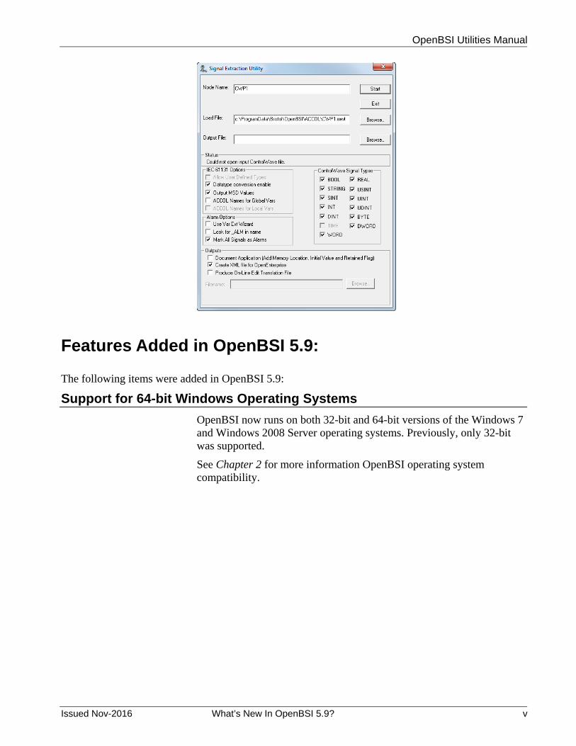
Signal Extractor change
The Signal Extractor now includes a new output option called Create XML file for OpenEnterprise.
If you are using OpenEnterprise 3.1 (or newer) check Create XML file for OpenEnterprise to allow Signal Extractor to generate an RTU definition for this device in XML that can be incorporated into the OE database.
OpenBSI Utilities Manual
Issued Nov-2016 What’s New In OpenBSI 5.9? v
Features Added in OpenBSI 5.9:
The following items were added in OpenBSI 5.9:
Support for 64-bit Windows Operating Systems
OpenBSI now runs on both 32-bit and 64-bit versions of the Windows 7 and Windows 2008 Server operating systems. Previously, only 32-bit was supported.
See Chapter 2 for more information OpenBSI operating system compatibility.

OpenBSI Utilities Manual
vi What’s New in OpenBSI 5.9? Issued Nov-2016
New Version of ControlWave Designer
OpenBSI 5.9 includes a new version of ControlWave Designer (Version 5.35). For information, see the online help within ControlWave Designer.
Variable Extension Wizard Enhancement for Variable Descriptive Text
A Store All Descriptors option has been added to take all variable descriptive text residing in the ControlWave project and add it to the INI file so the user can view it. Previously, users had to do this manually for each individual variable. See the ControlWave Designer Programmer’s Handbook (D5125) for more information.
Number of OpenBSI Networks Increased
OpenBSI 5.9 now supports up to 1,000 BSAP networks (including sub-networks). Previously the maximum number of networks was 99.
Harvester allows Pushdown Array/Archive Collection at Designated Hour
Harvester can now start historical collections of pushdown arrays and archives at a user-defined hour. Previously collections always began at midnight on the specified day. See the OpenBSI Harvester Manual (D5120) for more information.
.

OpenBSI Utilities Manual
Issued Nov-2016 Contents vii
Contents
Chapter 1 – Introduction – What is OpenBSI? 1-1 1.1 RTUs and NHPs ........................................................................................................................ 1-4
1.1.1 Remote Terminal Units (RTUs): .................................................................................... 1-4 1.1.2 Network Host PC (NHP) ................................................................................................ 1-4
1.2 Supported Network Configurations ........................................................................................... 1-5 1.3 BSAP Networks ......................................................................................................................... 1-5
1.3.1 Local and Global Addressing ........................................................................................ 1-5 1.3.2 Network Levels .............................................................................................................. 1-5 1.3.3 Supported Communication Methods in BSAP .............................................................. 1-6 1.3.4 Peer-to-Peer Communication ........................................................................................ 1-6 1.3.5 Variations on Standard BSAP – EBSAP ....................................................................... 1-7 1.3.6 Variations on Standard BSAP – BSAP Local Line ........................................................ 1-7
1.4 IP Networks ............................................................................................................................. 1-10 1.4.1 Applications Using IP .................................................................................................. 1-10 1.4.2 Differences between IP Nodes and Other RTUs ........................................................ 1-11 1.4.3 Controllers That Support IP ......................................................................................... 1-12 Format of IP Addresses .......................................................................................................... 1-13 Meaning of IP Address Components ...................................................................................... 1-13 Rules for Local Addressing Schemes .................................................................................... 1-14 Sub-net masks determine which nodes are reachable from a given node ............................ 1-15 1.4.4 Guidelines for Choosing Addresses in a Private Network .......................................... 1-17 1.4.5 IP Network Variations – Connecting Two Networks with a Single Router .................. 1-18 1.4.6 IP Network Variations - Using Multiple Routers (Gateways) and RIP for a Fault Tolerant Connection .............................................................................................................................. 1-22 1.4.7 IP Network Variations - Using Multiple Routers (Gateways) without RIP ................... 1-22
1.5 IP Network Security Protocols (CHAP and PAP) Used on PPP Links .................................... 1-24 1.5.1 Challenge Handshaking Authentication Protocol (CHAP) .......................................... 1-24 1.5.2 Password Authentication Protocol (PAP) .................................................................... 1-27
1.6 Mixed Networks (Both BSAP and IP nodes) ........................................................................... 1-29 Chapter 2 – Installing OpenBSI 2-1
2.1 Hardware and Software Requirements ..................................................................................... 2-2 2.1.1 Controllers used with OpenBSI ..................................................................................... 2-2 2.1.2 Recommended Hardware/Software for the OpenBSI Workstation: .............................. 2-2
2.2 Installing the OpenBSI Utilities .................................................................................................. 2-3 2.3 Registering Your Software ...................................................................................................... 2-10
2.3.1 How do I Register My Software? ................................................................................ 2-10 2.4 How to Transfer a License from One PC to another PC ......................................................... 2-17
2.4.1 Using the software… ................................................................................................... 2-22 2.5 Using OpenBSI with Newer Microsoft® Windows Operating Systems ................................... 2-22
2.5.1 Which OpenBSI Features are affected? ..................................................................... 2-23 2.5.2 How do I make these applications work properly with Windows? .............................. 2-23 What is a Firewall? ................................................................................................................. 2-23
2.6 Using OpenBSI with Microsoft® Windows XP Service Pack 2 ............................................... 2-24 2.6.1 Reconfiguring the Windows XP Firewall ..................................................................... 2-24 2.6.2 Disabling the Windows XP Firewall ............................................................................ 2-24 2.6.3 Making Object Server an Exception to the Windows XP Firewall............................... 2-24 2.6.4 Add Ports for DCOM and RTRSERVC for the XP firewall .......................................... 2-26 2.6.5 Add Ports for the Bristol IP Driver (BSIPDRV) for the XP firewall .............................. 2-28 2.6.6 Reconfiguring the DCOM Software for the XP firewall ............................................... 2-29
2.7 Using OpenBSI with Microsoft® Windows 2008 Server ......................................................... 2-34

OpenBSI Utilities Manual
viii Contents Issued Nov-2016
2.7.1 Reconfiguring the Windows 2008 Server Firewall ...................................................... 2-34 2.7.2 Disabling the Windows 2008 Server Firewall ............................................................. 2-34 2.7.3 Making Object Server an Exception to the Windows 2008 Server Firewall ................ 2-35 2.7.4 Add Ports for DCOM and RTRSERVC for the Windows 2008 Firewall ...................... 2-37 2.7.5 Add Ports for the Bristol IP Driver (BSIPDRV) for the Windows 2008 Server Firewall2-39 2.7.6 Reconfiguring the DCOM Software for the Windows 2008 Server Firewall ............... 2-41
2.8 Using OpenBSI with Microsoft® Windows 7 ........................................................................... 2-47 2.8.1 Reconfiguring the Windows 7 Firewall ........................................................................ 2-47 2.8.2 Disabling the Windows 7 Firewall ............................................................................... 2-47 2.8.3 Making Object Server an Exception to the Windows 7 Firewall ................................. 2-47 2.8.4 Add Ports for DCOM and RTRSERVC for the Windows 7 Firewall ............................ 2-56 2.8.5 Add Ports for the Bristol IP Driver (BSIPDRV) for the Windows 7 Firewall ................ 2-57 2.8.6 Reconfiguring the DCOM Software for the Windows 7 Firewall ................................. 2-59
2.9 Using OpenBSI with Microsoft® Windows 10 Professional .................................................... 2-59 2.9.1 Reconfiguring the Windows 10 Firewall ...................................................................... 2-59 2.9.2 Disabling the Windows 10 Firewall ............................................................................. 2-59 2.9.3 Making Object Server an Exception to the Windows 10 Firewall ............................... 2-60 2.9.4 Add Ports for DCOM and RTRSERVC for the Windows 10 Firewall .......................... 2-67 2.9.5 Add Ports for the Bristol IP Driver (BSIPDRV) for the Windows 10 Firewall .............. 2-68 2.9.6 Reconfiguring the DCOM Software for the Windows 10 Firewall ............................... 2-70
2.10 Using OpenBSI with Microsoft® Windows 2012 Server ......................................................... 2-70 2.10.1 Reconfiguring the Windows 2012 Server Firewall ...................................................... 2-70 2.10.2 Disabling the Windows 2012 Server Firewall ............................................................. 2-70 2.10.3 Making Object Server an Exception to the Windows 2012 Server Firewall ................ 2-71 2.10.4 Add Ports for DCOM and RTRSERVC for the Windows 2012 Server Firewall .......... 2-80 2.10.5 Add Ports for the Bristol IP Driver (BSIPDRV) for the Windows 2012 Server Firewall2-81 2.10.6 Reconfiguring the DCOM Software for the Windows 2012 Server Firewall ............... 2-83
2.11 Recommendations for Using OpenBSI ActiveX Controls ....................................................... 2-83 Chapter 3 – Quickstart (OpenBSI BSAP Communications) 3-1
3.1 Start NetView and Open a New Set of NETDEF Files ............................................................. 3-2 3.2 Use the System Wizard to Define Your Network Host PC (NHP)............................................. 3-4
3.2.1 System Wizard – Page 1 .............................................................................................. 3-4 3.2.2 System Wizard: Page 2 ................................................................................................ 3-5 3.2.3 System Wizard: Page 3 ................................................................................................ 3-6
3.3 Define Your BSAP Network Using the Network Wizard ........................................................... 3-8 3.3.1 Network Wizard: Page 1 ............................................................................................... 3-9 3.3.2 Network Wizard: Page 2 ............................................................................................. 3-10
3.4 Add Controllers to the BSAP Network Using the RTU Wizard ............................................... 3-11 3.4.1 RTU Wizard Page 1 .................................................................................................... 3-12 3.4.2 RTU Wizard Page 2 .................................................................................................... 3-13 3.4.3 RTU Wizard Page 3 .................................................................................................... 3-15
3.5 Define Your Communication Line using the Comm Line Wizard ............................................ 3-16 3.5.1 Comm Line Wizard Page 1 ......................................................................................... 3-17 3.5.2 Comm Line Wizard Page 2 ......................................................................................... 3-18
3.6 Verify Communications Are Active Using DataView ............................................................... 3-19 3.6.1 If NetView communicates…. ....................................................................................... 3-21 3.6.2 If NetView fails to communicate… .............................................................................. 3-22
Chapter 4 – Quickstart (OpenBSI IP Communications) 4-1
4.1 Using IP with ControlWave and Network 3000 RTUs ............................................................... 4-2 4.2 Start NetView and Open a New Set of NETDEF Files ............................................................. 4-3 4.3 Use the System Wizard to Define Your Network Host PC (NHP)............................................. 4-4

OpenBSI Utilities Manual
Issued Nov-2016 Contents ix
4.3.1 Function of the NHP in an IP Network .......................................................................... 4-4 4.3.2 System Wizard – Page 1 ............................................................................................... 4-5 4.3.3 System Wizard: Page 2 ................................................................................................. 4-6 4.3.4 System Wizard: Page 3 ................................................................................................. 4-7
4.4 Define Your IP Network Using the Network Wizard .................................................................. 4-9 4.4.1 Network Wizard: Page 1 ............................................................................................. 4-10 4.4.2 Network Wizard: Page 2 ............................................................................................. 4-11
4.5 Add Controllers to the IP Network Using the RTU Wizard ...................................................... 4-11 4.5.1 RTU Wizard Page 1 .................................................................................................... 4-12 4.5.2 RTU Wizard Page 2 .................................................................................................... 4-14 4.5.3 RTU Wizard Page 3 .................................................................................................... 4-15 4.5.4 RTU Wizard Page 4 .................................................................................................... 4-17
4.6 Set RTU Configuration Parameters in Each RTU ................................................................... 4-18 4.7 Define Your Communication Line using the Comm Line Wizard ............................................ 4-18
4.7.1 Comm Line Wizard Page 1 ......................................................................................... 4-19 4.7.2 Comm Line Wizard Page 2 ......................................................................................... 4-20
4.8 Verify Communications Are Active Using DataView ............................................................... 4-21 4.8.1 If NetView communicates…. ....................................................................................... 4-23 4.8.2 If NetView fails to communicate… .............................................................................. 4-24
Chapter 5 – Using LocalView 5-1
5.1 LocalView Operational Restrictions .......................................................................................... 5-2 5.2 View Mode Files ........................................................................................................................ 5-2 5.3 System Firmware and RTU Configuration Parameters............................................................. 5-2
5.3.1 System Firmware .......................................................................................................... 5-2 5.3.2 RTU Configuration Parameters ..................................................................................... 5-3 5.3.3 OpenBSI Application Parameters ................................................................................. 5-3
5.4 Methods for Starting LocalView ................................................................................................ 5-3 5.5 Establishing Communications with an Attached RTU (Local Mode) ......................................... 5-4
5.5.1 Before You Begin .......................................................................................................... 5-4 5.5.2 Starting LocalView and the Setup Wizards ................................................................... 5-5 5.5.3 Communications Setup Wizard ..................................................................................... 5-6 5.5.4 RTU Setup Wizard ........................................................................................................ 5-8 5.5.5 Dial & Command Setup Wizard .................................................................................... 5-9
5.6 After You Have Finished With the Setup Wizards… ............................................................... 5-10 5.6.1 Starting Other Programs in Local Mode ...................................................................... 5-11 5.6.2 Reconfiguring the Active View Mode File ................................................................... 5-13 5.6.3 Saving the View Mode File .......................................................................................... 5-13 5.6.4 Restarting the View Mode File .................................................................................... 5-14 5.6.5 Viewing Current Configuration Parameters ................................................................ 5-14
5.7 Upgrading System Firmware in the Field (Flash Mode) ......................................................... 5-14 5.7.1 Before You Upgrade the System Firmware ................................................................ 5-15 5.7.2 Starting LocalView and the Setup Wizards ................................................................. 5-16 5.7.3 Communications Setup Wizard ................................................................................... 5-16 5.7.4 Flash RTU Setup Wizard ............................................................................................ 5-17 5.7.5 Flash Data Setup Wizard ............................................................................................ 5-19 5.7.6 Setting RTU Configuration Parameters in the 3305 (3305 ONLY) ............................. 5-21
5.8 Assigning IP Addresses and Cold Download Parameters for the Attached RTU (Configure Mode) ................................................................................................................................................ 5-23 5.8.1 Starting LocalView and the Setup Wizards ................................................................. 5-23 5.8.2 Communications Setup Wizard ................................................................................... 5-23 5.8.3 IP RTU Setup Wizard .................................................................................................. 5-24
5.9 Setting RTU Parameters in the Flash Configuration Utility ..................................................... 5-26

OpenBSI Utilities Manual
x Contents Issued Nov-2016
5.9.1 Flash Configuration Utility Buttons .............................................................................. 5-30 5.9.2 Forcing a Reboot of the ControlWave ......................................................................... 5-34 5.9.3 Flash Configuration Utility Tabs .................................................................................. 5-34 5.9.4 Soft Switches .............................................................................................................. 5-35 5.9.5 Ports ............................................................................................................................ 5-37 5.9.6 IP Parameters ............................................................................................................. 5-49 5.9.7 Application Parameters ............................................................................................... 5-54 5.9.8 Archive ........................................................................................................................ 5-57 5.9.9 Audit ............................................................................................................................ 5-62 5.9.10 IP Routes .................................................................................................................... 5-65 5.9.11 Security ....................................................................................................................... 5-67
5.10 Establishing Communications With an IP RTU (IP Comm Mode) .......................................... 5-72 5.10.1 Starting LocalView and the Setup Wizards ................................................................. 5-72 5.10.2 IP Communications Setup Wizard (Step 1 of 3) ......................................................... 5-73 5.10.3 IP Communications Setup Wizard (Step 2 of 3) ......................................................... 5-74 5.10.4 IP Communications Setup Wizard (Step 3 of 3) ......................................................... 5-75
Chapter 6 – Using NetView 6-1
6.1 Starting NetView ....................................................................................................................... 6-3 6.1.1 Network Definition (NETDEF) Files .............................................................................. 6-4 6.1.2 Starting OpenBSI Communications When Windows Starts.......................................... 6-4 6.1.3 Starting NETVIEW from the Command Line ................................................................ 6-7
6.2 Starting OpenBSI Communications .......................................................................................... 6-7 6.2.1 Restarting a Communication Line ................................................................................. 6-8
6.3 Stopping OpenBSI Communications ........................................................................................ 6-8 6.3.1 Method 1: Stop the Communication Line ...................................................................... 6-8 6.3.2 Method 2: Close the Current NETDEF files. ................................................................. 6-8 6.3.3 Method 3: Shut down NetView. ..................................................................................... 6-8
6.4 Opening an Existing Set of NETDEF Files ............................................................................... 6-9 6.5 Saving Changes to Your NETDEF Files ................................................................................. 6-10 6.6 Erasing the Last Change Made to Your NETDEF Files .......................................................... 6-10 6.7 Renaming the Currently Running NETDEF Files ................................................................... 6-10 6.8 Overview of Configuration ....................................................................................................... 6-10 6.9 Defining an NHP and Application Parameters ........................................................................ 6-11
6.9.1 What is A Network Host PC (NHP)? ........................................................................... 6-11 6.9.2 Activating the System Wizard ..................................................................................... 6-15 6.9.3 Navigating Between Pages of the System Wizard ..................................................... 6-15 6.9.4 System Wizard: Step 1 of 3 ........................................................................................ 6-15 6.9.5 System Wizard: Step 2 of 3 ........................................................................................ 6-20 6.9.6 System Wizard: Step 3 of 3 ........................................................................................ 6-25 6.9.7 Signing on to the System ............................................................................................ 6-27 6.9.8 Signing Off .................................................................................................................. 6-28
6.10 Configuring OpenBSI Security ................................................................................................ 6-29 6.10.1 Users, Usernames, and Passwords ............................................................................ 6-29 6.10.2 Default User (SYSTEM) .............................................................................................. 6-29 6.10.3 Assigning or Changing the Password of the Current User ......................................... 6-30 6.10.4 Adding a New User ..................................................................................................... 6-30 6.10.5 Modifying Passwords, Privileges for an Existing User ................................................ 6-32 6.10.6 Removing a User from the Security System ............................................................... 6-33
6.11 Viewing / Modifying Application Parameters ........................................................................... 6-33 6.12 Viewing Other Parameters You Have Already Defined .......................................................... 6-34 6.13 Viewing the OpenBSI Journal File .......................................................................................... 6-35 6.14 Defining a BSAP Network ....................................................................................................... 6-36
OpenBSI Utilities Manual
Issued Nov-2016 Contents xi
6.14.1 Activating the Network Wizard .................................................................................... 6-36 6.14.2 Navigating Between Pages of the Network Wizard .................................................... 6-37 6.14.3 Network Wizard: Step 1 of 2 ....................................................................................... 6-38 6.14.4 Network Wizard: Step 2 of 2 ....................................................................................... 6-39 6.14.5 Viewing BSAP Network Parameters ........................................................................... 6-39
6.15 Defining an IP Network ........................................................................................................... 6-41 6.15.1 Activating the Network Wizard .................................................................................... 6-41 6.15.2 Navigating Between Pages of the Network Wizard .................................................... 6-41 6.15.3 Network Wizard: Step 1 of 2 ....................................................................................... 6-42 6.15.4 Network Wizard: Step 2 of 2 ....................................................................................... 6-43 6.15.5 Viewing IP Network Parameters ................................................................................. 6-43
6.16 Defining RTUs (BSAP) ............................................................................................................ 6-44 6.16.1 Activating the RTU Wizard .......................................................................................... 6-45 6.16.2 Navigating Between Pages of the RTU Wizard .......................................................... 6-46 6.16.3 RTU Wizard: Step 1 of 3 ............................................................................................. 6-46 6.16.4 RTU Wizard: Step 2 of 3 ............................................................................................. 6-47 6.16.5 RTU Wizard: Step 3 of 3 ............................................................................................. 6-51 6.16.6 Modifying BSAP RTU Parameters .............................................................................. 6-52
6.17 Defining RTUs (IP) .................................................................................................................. 6-54 6.17.1 Activating the RTU Wizard .......................................................................................... 6-54 6.17.2 Navigating Between Pages of the RTU Wizard .......................................................... 6-55 6.17.3 RTU Wizard: Step 1 of 4 ............................................................................................. 6-55 6.17.4 RTU Wizard: Step 2 of 4 ............................................................................................. 6-57 6.17.5 RTU Wizard: Step 3 of 4 ............................................................................................. 6-59 6.17.6 RTU Wizard: Step 4 of 4 ............................................................................................. 6-61 6.17.7 Modifying IP RTU Parameters .................................................................................... 6-63
6.18 Defining a Communication Line for a BSAP Network ............................................................. 6-65 6.18.1 Activating the Comm Line Wizard ............................................................................... 6-65 6.18.2 Navigating Between Pages of the Comm Line Wizard ............................................... 6-66 6.18.3 Comm Line Wizard: Step 1 ......................................................................................... 6-66 6.18.4 Comm Line Wizard: Step 2 (BSAP and/or EBSAP Lines) ........................................ 6-67 6.18.5 Comm Line Wizard: Step 2 (Local BSAP Line) ........................................................... 6-70 6.18.6 Switching the Local Line to a Different RTU ............................................................... 6-72 6.18.7 Specifying Dial Parameters (NetView or LocalView) .................................................. 6-72 6.18.8 Forcing a Hang-up of the Dial-up Line ........................................................................ 6-74 6.18.9 Comm Line Wizard: Step 3 (Enable Port Poll Control - OPTIONAL) .......................... 6-74 6.18.10 Exiting the Comm Line Wizard ................................................................................. 6-76 6.18.11 Modifying the Characteristics of a BSAP Comm Line .............................................. 6-76 6.18.12 Modifying the Characteristics of a Local BSAP Line ................................................ 6-78
6.19 Defining a Communication Line for an IP Network ................................................................. 6-79 6.19.1 Activating the Comm Line Wizard ............................................................................... 6-79 6.19.2 Comm Line Wizard: Step 1 of 2 .................................................................................. 6-80 6.19.3 Comm Line Wizard: Step 2 of 2 .................................................................................. 6-81 6.19.4 Advanced Parameters ................................................................................................. 6-84 6.19.5 Navigating Between Pages of the Comm Line Wizard ............................................... 6-85 6.19.6 Exiting the Comm Line Wizard .................................................................................... 6-85 6.19.7 Modifying the Characteristics of an IP Comm Line ..................................................... 6-85
6.20 Deleting A Communication Line, RTU, or Network ................................................................. 6-88 6.21 Monitoring the Status of OpenBSI Communications ............................................................... 6-88

OpenBSI Utilities Manual
xii Contents Issued Nov-2016
6.21.1 Accessing the Monitor Windows ................................................................................. 6-88 6.21.2 Using the RTU Summary Display ............................................................................... 6-89 6.21.3 Resetting the RTU Statistics: ...................................................................................... 6-90 6.21.4 Getting More Detailed Information about an RTU ...................................................... 6-90 6.21.5 Using the RTU Details Display .................................................................................... 6-91 6.21.6 Using the RTU Details Display for a BSAP/EBSAP RTU: .......................................... 6-91 6.21.7 Using the RTU Details Display for an IP RTU: ........................................................... 6-94 6.21.8 Using the Message Exchange Summary Display ....................................................... 6-96 6.21.9 Resetting the Message Exchange Statistics: .............................................................. 6-97 6.21.10 Getting More Detailed Information about a Message Exchange ............................. 6-97 6.21.11 Using the Message Exchange Details Display ........................................................ 6-97 6.21.12 Buffer Usage Summary Display ............................................................................... 6-99 6.21.13 Resetting the Buffer Statistics: ............................................................................... 6-100 6.21.14 Other Ways to View Communication Statistics ...................................................... 6-101
6.22 RTU Communication Status Checking ................................................................................. 6-102 6.22.1 Activating / De-activating RTU Communication Status Checking ............................ 6-102
6.23 Searching For A Particular RTU in A Large Network ............................................................ 6-103 6.24 Starting Other Programs From Within NetView .................................................................... 6-104 6.25 Documenting Your Network Configuration ............................................................................ 6-106 6.26 Setting up Proxy Access ....................................................................................................... 6-107
6.26.1 Steps for Setting up Proxy Access ............................................................................ 6-108 6.26.2 Steps for Setting up Proxy Direct Access (IP RTU's ONLY) .................................... 6-108 6.26.3 Creating and Exporting a Proxy File ......................................................................... 6-109 6.26.4 Importing a Proxy File ............................................................................................... 6-110
6.27 Sending a Time Synch/NRT (TS/NRT) Message ................................................................. 6-110 6.28 Deleting Archive Files and/or Audit Records ....................................................................... 6-111
6.28.1 Deleting Historical Data ............................................................................................ 6-111 Chapter 7 – Using the Downloaders 7-1
7.1 Starting the ACCOL Downloader .............................................................................................. 7-1 7.2 Downloading to a Single Network 3000 Node .......................................................................... 7-3 7.3 Downloading to a Group of Network 3000 Nodes .................................................................... 7-3 7.4 Downloading to a ControlWave-series Node: ........................................................................... 7-6
7.4.1 Before You Begin .......................................................................................................... 7-6 7.4.2 Starting the ControlWave Downloader.......................................................................... 7-9 7.4.3 Using the ControlWave Downloader ........................................................................... 7-10 7.4.4 Creating Download Scripts for Batch Downloading of ControlWave Controllers ....... 7-11 7.4.5 Running the ControlWave Downloader from the Command Line ............................... 7-13
Chapter 8 – Using DataView 8-1
8.1 Starting DataView ..................................................................................................................... 8-2 8.2 Using the Tool Bar within DataView .......................................................................................... 8-3 8.3 Using the Select New Node Dialog Box, Signing on to a Node ................................................ 8-3
Using the Select New Node Dialog Box .................................................................................. 8-4 Using the Sign On Dialog Box .................................................................................................. 8-4 Configuring Automatic DataView Sign-On ............................................................................... 8-5
8.4 Printing the Entries in the Current DataView Window .............................................................. 8-6 8.5 Exporting Data Entries to the Windows Clipboard ................................................................. 8-6 8.6 Conducting a Signal Search ..................................................................................................... 8-7
Starting the Signal Search ........................................................................................................ 8-7 Notes about STRING variables .............................................................................................. 8-12 Saving Search Criteria ............................................................................................................ 8-13 Retrieving Search Criteria ...................................................................................................... 8-13 Altering Search Criteria .......................................................................................................... 8-13
8.7 Viewing Entries in a Signal Window ........................................................................................ 8-14

OpenBSI Utilities Manual
Issued Nov-2016 Contents xiii
Changing Signal Values in the Signal Window ...................................................................... 8-15 Changing Signal Inhibit/Enable Bits in the Signal Window .................................................... 8-16 Changing the Floating Point Format of Data in the Signal Window ....................................... 8-16
8.8 Displaying a Remote Signal List ............................................................................................. 8-17 Selecting a Different Remote Signal List ................................................................................ 8-17 Changing Remote List Signal Values, Altering Inhibit/Enable Bits ......................................... 8-18
8.9 Creating and Using DataView Lists ........................................................................................ 8-18 Creating a DataView List ........................................................................................................ 8-18 Collecting Live Data into the DataView List ............................................................................ 8-19 Saving the DataView List ........................................................................................................ 8-19 Viewing a Previously Saved DataView List ............................................................................ 8-19
8.10 Creating and Using Recipes ................................................................................................... 8-19 Creating a Recipe ................................................................................................................... 8-20 To View/Modify an Existing Recipe File ................................................................................. 8-21 To Update Signals in the Controller with the Recipe Values .................................................. 8-21 To Read the Current Signal Values From the Controller Into the Recipe Window ................ 8-21 To Cancel Unsaved Modifications to the Recipe Values........................................................ 8-21 Changing the Floating Point Format of Data in the Recipe Window ...................................... 8-21
8.11 Viewing Data for a Single Signal ............................................................................................. 8-22 Acknowledging an Alarm ........................................................................................................ 8-23
8.12 Viewing Data Arrays ................................................................................................................ 8-23 Changing Values in the Data Array ........................................................................................ 8-24 Toggling the Time/Value Format ............................................................................................ 8-25 Keeping Column 1 Visible While Scrolling Through the Array ............................................... 8-25 Calling Up a Different Data Array ........................................................................................... 8-25 Changing the Floating Point Format ....................................................................................... 8-25
8.13 Viewing Audit Trail Records .................................................................................................... 8-26 8.14 Viewing Archive Data Files ..................................................................................................... 8-28
Keeping Column 1 Visible While Scrolling Through the Archive File ..................................... 8-29 Calling Up a Different Archive File .......................................................................................... 8-29 Changing the Floating Point Format ....................................................................................... 8-29 Restrictions on Archive File Size ............................................................................................ 8-29
Chapter 9 – Using the Communication Statistics Tool 9-1
9.1 Starting the Remote Communication Statistics Tool ................................................................. 9-2 9.2 Using the Select New Node Dialog Box, Signing On to a Node ............................................... 9-3
Using the Select New Node Dialog Box ................................................................................... 9-4 Using the Sign On Dialog Box .................................................................................................. 9-4 Configuring Automatic Sign-On ................................................................................................ 9-5
9.3 Buffer Usage Statistics Window (Network 3000 ONLY) ........................................................... 9-6 Indications of Buffer Shortages ................................................................................................ 9-7 Resetting the Min, Max Counts ................................................................................................ 9-7 Crash Block Statistics Window ................................................................................................. 9-7
9.4 Port Summary Statistics Window .............................................................................................. 9-8 Port Detail Statistics Window .................................................................................................... 9-9 Master/Expanded Addressing Master Port Statistics ............................................................. 9-10 Slave, Pseudo-Slave, Pseudo-Slave with Alarms, Serial CFE or VSAT Slave Port Statistics9-11 Custom Port Statistics (ControlWave-series Users ONLY) .................................................... 9-11 RIOR Master Port Statistics .................................................................................................... 9-12 RIOR Slave Port Statistics ...................................................................................................... 9-13 LIU Master Port Statistics ....................................................................................................... 9-14 LIU Slave Port Statistics ......................................................................................................... 9-15 Communications Front End (CFE) AUX Port Statistics .......................................................... 9-17 Internet Protocol (IP) Port Statistics ....................................................................................... 9-17
9.5 Custom PROM Information Window (Network 3000) ............................................................. 9-19 9.6 Version Information Window ................................................................................................... 9-21 9.7 Node Routing Table Window .................................................................................................. 9-23 9.8 Internet Protocol (IP) Statistics Window .................................................................................. 9-24

OpenBSI Utilities Manual
xiv Contents Issued Nov-2016
IP Statistics Decription ............................................................................................................ 9-25 ICMP Statistics Description .................................................................................................... 9-26 UDP Statistics Description ...................................................................................................... 9-27 IBP Statistics Description ....................................................................................................... 9-28
9.9 Printing the Entries in the Current Window ............................................................................. 9-29 9.10 Exporting Data Entries to the Windows® Clipboard ................................................................ 9-29
Chapter 10 – Using Signal Writer 10-1
10.1 Starting Signal Writer .............................................................................................................. 10-1 10.2 Setting Up Signal Writer Configuration Parameters ............................................................... 10-2 10.3 Signal Writer File Formats ....................................................................................................... 10-3
10.3.1 Write Signal File .......................................................................................................... 10-3 10.3.2 Write List File .............................................................................................................. 10-3
Chapter 11 – Using Alarm Router 11-1
11.1 Starting Alarm Router .............................................................................................................. 11-2 11.2 How is the Alarm Router Configured? .................................................................................... 11-2 11.3 Specifying Initialization Parameters and Choosing DLLs ....................................................... 11-3
11.3.1 Parameter Configuration Page ................................................................................... 11-3 DLL Configuration Page ......................................................................................................... 11-5 11.3.2 Activating A DLL .......................................................................................................... 11-5 11.3.3 Removing A DLL From the Configured DLLs List Box ............................................... 11-5 11.3.4 Installing An All New DLL ............................................................................................ 11-6 11.3.5 Removing A DLL from the Available DLLs List Box .................................................... 11-6
11.4 Configuring Alarm Router DLLs .............................................................................................. 11-6 11.4.1 ALMTEXT DLL ............................................................................................................ 11-7 11.4.2 ALMWORX DLL .......................................................................................................... 11-8
11.5 Viewing Alarms in the Alarm Window ................................................................................... 11-10 11.5.1 Acknowledging Selected Alarms in the Alarm Window ............................................ 11-13 11.5.2 Changing the Font Used in the Alarm, Error, and Monitor Windows ........................ 11-14
11.6 Viewing Status Messages in the Monitor Window ................................................................ 11-15 11.6.1 List of Monitor Window Status Messages and Their Meanings ................................ 11-16
11.7 Viewing Error Messages in the Error Window ...................................................................... 11-17 11.7.1 Clearing Errors from the Error Window ..................................................................... 11-18 11.7.2 List of Error Messages and Their Meanings ............................................................. 11-18
11.8 Starting Alarm Processing..................................................................................................... 11-19 11.9 Stopping Alarm Processing ................................................................................................... 11-19 11.10 Printing Entries in Alarm Router Windows ............................................................................ 11-19 11.11 Shutting Down the Alarm Router .......................................................................................... 11-19 11.12 Editing the Configuration Files .............................................................................................. 11-19
11.12.1 ALARMRTR.INI File ............................................................................................... 11-20 11.12.2 ALMTEXT.INI File .................................................................................................. 11-20 11.12.3 ALMWRX.INI File ................................................................................................... 11-20
11.13 Program Messages ............................................................................................................... 11-21 Chapter 12 – Using the Signal Extractor 12-1
12.1 Starting the Signal Extractor ................................................................................................... 12-1 12.2 Signal Extract Options for Network 3000 Nodes .................................................................... 12-2
12.2.1 Standard File Format – Network 3000 Series Controllers .......................................... 12-3 12.2.2 Altered File Formats – Network 3000 / ControlWave ................................................. 12-5
12.3 Signal Extract Options for ControlWave ................................................................................. 12-7 12.4 Standard File Format – ControlWave Controllers ................................................................. 12-11
12.4.1 Example 1 - Standard Format ................................................................................... 12-12 12.5 Running Signal Extractor from the DOS Command Line ...................................................... 12-13 12.6 Troubleshooting Tips for Using Signal Extractor with ControlWave ..................................... 12-14

OpenBSI Utilities Manual
Issued Nov-2016 Contents xv
Chapter 13 – Using the Data Array Save / Restore Utility 13-1 13.1 Saving the Contents of a Single Array to Disk ........................................................................ 13-1 13.2 Restoring the Values in a Single Array from a Previously Saved File .................................... 13-3 13.3 Creating a Script File to Save Multiple Arrays from One or More RTUs................................. 13-3
13.3.1 Creating a Script File ................................................................................................... 13-3 13.3.2 Executing the Script File to Save Multiple Arrays to Disk Files .................................. 13-5
13.4 Executing a Script to Restore Multiple Arrays from Previously Saved Disk Files ................... 13-6 13.5 Running a Script from the Command Line .............................................................................. 13-6
Chapter 14– Using the Network Troubleshooting Wizard 14-1
14.1 Before you Begin ..................................................................................................................... 14-1 14.2 Starting the Network Troubleshooting Wizard ........................................................................ 14-2 14.3 Testing a BSAP Network or BSAP Sub-Network .................................................................... 14-3
14.3.1 Step 1. Select the BSAP Network (or BSAP Sub-network) ........................................ 14-3 14.3.2 Step 2. - Specify the Branch of the Network you want to test ..................................... 14-4 14.3.3 Step 3. - Choose Which Tests to Perform .................................................................. 14-5 14.3.4 Setting Test Options: ................................................................................................... 14-7 14.3.5 Step 4. – Run the Tests .............................................................................................. 14-8 14.3.6 Saving the Results of the Network Tests .................................................................. 14-10
14.4 Interpreting the Messages Appearing in the Results Window .............................................. 14-10 14.4.1 Status Messages ....................................................................................................... 14-10 14.4.2 Error Messages ......................................................................................................... 14-11 14.4.3 Warning Messages ................................................................................................... 14-13
14.5 Making Changes at the OpenBSI Workstation (NHP) .......................................................... 14-17 14.5.1 Changing the Number of Buffers allocated at the OpenBSI Workstation ................. 14-17 14.5.2 Changing the Number of Wait Packets allocated in the OpenBSI Workstation ........ 14-18 14.5.3 Changing the RTU Message Timeout Used by OpenBSI ......................................... 14-18 14.5.4 Changing OpenBSI’s baud rate, poll period, slave address range, and link level timeout14-20
14.6 Making Changes in the Network 3000 series node .............................................................. 14-22 14.6.1 Changing the Number of Buffers in a Network 3000 series node ............................. 14-22 14.6.2 Changing the Baud Rate of a Port in a Network 3000 Node .................................... 14-23 14.6.3 Changing the Link Level Timeout, and range of Slave addresses for a Master Port in a Network 3000 node .............................................................................................................. 14-25 14.6.4 Changing the Poll Period of a Port in a Network 3000 Node .................................... 14-26
14.7 Making Changes in the ControlWave series node ................................................................ 14-29 14.7.1 Specifying the Baud rate and (for Master Ports only) the range of Slave node Addresses 14-29 14.7.2 Changing Poll Periods and the Link Level Timeout in a ControlWave Node ............ 14-30
14.8 Some Notes about Setting Immediate Response Delays ..................................................... 14-32
Appendix A – Error and Status Messages A-1
Appendix B – NETDEF File Format B-1
Appendix C – Keyboard Shortcuts C-1
Appendix D – Modem and Radio Configuration Tips D-1
Appendix E – Initialization Files E-1
Appendix F – Signal View ActiveX Controls F-1
Appendix G – Redirecting BSAP Messages through TCP/IP G-1
Appendix H – Defining Backup Communication Lines H-1
Appendix I – Port Arbitrator I-1
Appendix J – Using the System Firmware Downloader J-1
J.2 Requirements for Using the System Firmware Downloader ............................................................................................................................................................................................................................................................................................................................................................................................................................................................................................................................................................................................................................................................................................................................................................................................................................................................................................................................................................................................................................................................................................................................................................................................................................................................................................................................................................. J-1 J.3 Starting the System Firmware Downloader ..................................................................................................................................................................................................................................................................................................................................................................................................................................................................................................................................................................................................................................................................................................................................................................................................................................................................................................................................................................................................................................................................................................................................................................................................................................................................................................................................................................................... J-2
to a Single Controller J-3 J-8
Appendix K – Interpreting AUDIT Messages K-1

OpenBSI Utilities Manual
xvi Contents Issued Nov-2016
Addendum to D5081, D5087: Starting Web Pages or Programs using LocalView (*.LVG) Files ADD-1
Index IND-1

OpenBSI Utilities Manual
Issued Nov-2016 Introduction 1-1
Chapter 1 – Introduction – What is OpenBSI?
The Open Bristol System Interface (OpenBSI) allows your PC to communicate with a BSAP or IP network of ControlWave and/or Network 3000-series controllers (RTUs). This chapter introduces some of the concepts and terminology used in OpenBSI.
In This Chapter
1.1 RTUs and NHPs .............................................................................. 1-4 1.1.1 Remote Terminal Units (RTUs): ........................................... 1-4 1.1.2 Network Host PC (NHP) ....................................................... 1-4
1.2 Supported Network Configurations .................................................. 1-5 1.3 BSAP Networks ............................................................................... 1-5
1.3.1 Local and Global Addressing ............................................... 1-5 1.3.2 Network Levels ..................................................................... 1-5 1.3.3 Supported Communication Methods in BSAP ..................... 1-6 1.3.4 Peer-to-Peer Communication ............................................... 1-6 1.3.5 Variations on Standard BSAP – EBSAP .............................. 1-7 1.3.6 Variations on Standard BSAP – BSAP Local Line ............... 1-7
1.4 IP Networks .................................................................................... 1-10 1.4.1 Applications Using IP ......................................................... 1-10 1.4.2 Differences between IP Nodes and Other RTUs ............... 1-11 1.4.3 Controllers That Support IP ................................................ 1-12 Format of IP Addresses ................................................................. 1-13 Meaning of IP Address Components ............................................. 1-13 Rules for Local Addressing Schemes ............................................ 1-14 Sub-net masks determine which nodes are reachable from
a given node ..................................................................... 1-15 1.4.4 Guidelines for Choosing Addresses in a Private Network . 1-17 1.4.5 IP Network Variations – Connecting Two Networks with a Single
Router ............................................................................... 1-18 1.4.6 IP Network Variations - Using Multiple Routers (Gateways) and
RIP for a Fault Tolerant Connection ................................. 1-22 1.4.7 IP Network Variations - Using Multiple Routers (Gateways)
without RIP........................................................................ 1-22 1.5 IP Network Security Protocols (CHAP and PAP) on PPP Links .... 1-24
1.5.1 Challenge Handshaking Authentication Protocol (CHAP) . 1-24 1.5.2 Password Authentication Protocol (PAP) ........................... 1-27
1.6 Mixed Networks (Both BSAP and IP nodes) ................................. 1-29
OpenBSI also includes a suite of programs known as the OpenBSI utilities that interact with the network to allow you to:
Download ControlWave Designer projects and web pages to ControlWave series RTUs.
Download ACCOL load files to Network 3000-series RTUs. Collect and display data from the RTUs. Monitor and control OpenBSI communications. SCADA applications, such as OpenEnterprise, use OpenBSI communications, and data files generated by OpenBSI utilities, to

OpenBSI Utilities Manual
1-2 Introduction Issued Nov-2016
access the network in order to display and report information from field instrumentation about a running process. You can then use this information to interact with the network and your process.
Figure 1-1. OpenBSI Architecture
You access the OpenBSI utilities from the Start Programs menu on the PC. Table 1-1 provides a brief description of each utility.
Table 1-1. OpenBSI Utilities
Icon Utility Description
NetView starts OpenBSI communications and allows you to define details about how OpenBSI should work. It includes a series of software “wizards” to help you specify characteristics of the communication network, as well as the remote process controllers (RTUs) which make up the network. NetView allows you to communicate with controllers in standard BSAP networks, in EBSAP networks, and in Internet Protocol (IP) networks. It also lets you specify system directory and file locations. NetView allows you to make on-line changes to the system configuration, and also helps you monitor the “health” of OpenBSI communications. See Chapter 6 – Using NetView.
The ACCOL Downloader transfers a linked ACCOL load file (*.ACL) from the PC to a running Network 3000-series RTU. The 1131 Downloader transfers web pages (HTML) and ControlWave Designer projects to ControlWave series RTUs. See Chapter 7 - Using the Downloader .

OpenBSI Utilities Manual
Issued Nov-2016 Introduction 1-3
Icon Utility Description
DataView collects and displays several types of process data from a controller, including signal values, data array values, signal lists, archive data, and audit trail information. In addition, it lets you search for signals based on various criteria. See Chapter 8 - Using DataView.
Remote Communication Statistics Tool allows you to monitor OpenBSI communication from the RTU end. It provides details on buffer usage, communication ports, and custom protocols. See Chapter 9 - Using the Remote Communication Statistics Tool .
LocalView communicates locally with an RTU, and, for certain controllers, also allows field upgrades of system firmware. LocalView also lets you configure cold download parameters and Internet Protocol (IP) addresses for 386EX Protected Mode RTUs and ControlWave RTUs. See Chapter 5 – Using LocalView.
Alarm Router collects alarm data from the network and displays it in a window for you to view. It also exports the alarm data to OpenEnterprise or other SCADA packages which provide alarm management capabilities. See Chapter 11 – Using Alarm Router.
Signal Writer reads ASCII files containing signal values, and writes those values to corresponding signals or signal lists in the RTU. SigWrite scans for such files at a user-definable interval. See Chapter 10 - Using Signal Writer.
Signal Extractor reads an ACCOL Object (*.ACO) file or ControlWave Designer MWT file and generates an ASCII text file containing information about all global, alarm, and report by exception (RBE) signals defined in the file. Other user-specific applications use this file to construct a database. See Chapter 12 - Using the Signal Extractor.
Database Config Utility allows you to modify database portions of the OpenBSI 3.1 (or newer) Network Definition Files offline. This provides an alternative to using NetView to make modifications. Note: You can only modify existing components; you cannot add or delete items. See Appendix B.

OpenBSI Utilities Manual
1-4 Introduction Issued Nov-2016
Icon Utility Description
Data Array Save / Restore Utility allows you to collect data arrays from an RTU and then store them in disk file(s) at the OpenBSI workstation. You can retrieve the file for a particular array, at a later time, to restore the original array values from the file into the array at the RTU. See Chapter 13- Using the Data Array Save / Restore Utility for details.
In addition to the standard set of utilities, just described, there are other utilities, available as separate kits which provide capabilities for scheduled data collection and file export such as the Harvester. See the OpenBSI Harvester Manual (document# D5120) for details.
1.1 RTUs and NHPs
For purposes of this discussion, a network refers to one or more RTUs connected using communication line(s) to a Network Host PC (NHP) running OpenBSI.
1.1.1 Remote Terminal Units (RTUs):
Controllers are generically referred to in OpenBSI software by the term RTU (Remote Terminal Unit); we use the term controller and RTU interchangeably in this manual.
OpenBSI supports the ControlWave series of RTUs, as well as the older Network 3000 series (3305, 3308, 3310, 3330, 3335, 3530-xx).
Field instrumentation devices (pressure transmitters, temperature transmitters, level transmitters, electrical contacts, etc.) provide data input/output to the controller (RTU) through the controller's process I/O boards. The control strategy/load program executing in the controller accesses this data to perform measurement and control tasks, tailored specifically for your application (e.g. pipeline monitoring, pump control, industrial automation, etc.).
Each RTU serves as a node in the network, and communicates with other RTUs and OpenBSI workstations through its communication ports. You can also configure an RTU to communicate with certain third-party devices (PLCs, etc.) or networks though the use of a custom communication protocol.
1.1.2 Network Host PC (NHP)
The term Network Host PC (NHP) refers to any PC workstation running OpenBSI Version 3.0 or newer software. Typically, you connect RTUs to it (so it serves as the host for those RTUs). You use NetView (described in Chapter 6) to define the RTUs in the NHP’s Network Definition (NETDEF) files. Any other NHP can only gain

OpenBSI Utilities Manual
Issued Nov-2016 Introduction 1-5
access to these RTUs if this NHP allows it. The other NHP does not need the address of the RTU it wants to communicate with; it only needs to know the address of the NHP which is hosting the RTU, and the RTU's name.
An OpenBSI workstation without attached RTUs though still considered an NHP, serves as a proxy workstation. A proxy workstation contacts other NHP(s) which do have attached RTUs, and requests proxy access to those RTUs. Depending upon the type of network configuration, you configure the proxy access as either direct to the RTU or only through the RTU’s NHP.
In addition to running OpenBSI, each NHP typically also runs some form of supervisory control and data acquisition (SCADA) or human machine interface (HMI) software to display data collected from RTUs for an operator. OpenEnterprise is the most common SCADA/HMI package used with OpenBSI.
1.2 Supported Network Configurations
OpenBSI supports the following basic network configurations:
BSAP Networks IP Network(s) Mixed Network (mixture of IP and BSAP)
1.3 BSAP Networks
OpenBSI and all of the RTUs listed previously can communicate using the BSAP protocol. For advanced users who want to see a full description of BSAP, see the Network 3000 Communications Application Programmer’s Reference (document# D4052).
1.3.1 Local and Global Addressing
Based on its location in the network, you use NetView to assign a local address to each RTU in a BSAP network. The local address is an integer from 1 to 127 and NetView stores it as 7 bits. NetView also generates a 15-bit global address based on the local address. The local address you configure in NetView must match the local address hardware switch setting (or configuration parameter) set at the RTU.
1.3.2 Network Levels
BSAP networks use a hierarchical structure of 1 to 6 levels. You define this hierarchy in NetView. Figure 1-2 shows an example of a 3-level network.
Each RTU (node) serves as a “master” to the nodes connected immediately below it in the network, and as a “slave” to a single master on the level immediately above it. No single master node can have more than 127 slave nodes. Note: NetView may impose additional restrictions on the network size based on limitations of the 15 bit global

OpenBSI Utilities Manual
1-6 Introduction Issued Nov-2016
address.
A network master (which in OpenBSI is always the NHP) sits at the top of the network, and polls top-level nodes (nodes on level 1) for data. Each top-level node is a master to the nodes connected to it on level 2, and the level 2 nodes are masters to the nodes connected to them on level 3, and so on.
Figure 1-2. Network Levels
Data from the lowest level of the network passes from slave to master to slave to master etc. until it reaches the network master (NHP). At the NHP, you access the data using various OpenBSI utilities and SCADA software.
The level on which a node resides indicates the number of communication lines traversed to reach the network master. For example, a node on level 2 must send/receive data through two separate communication lines to reach the network master.
Note: Certain types of RTUs, for example, the 3308, can only serve as terminal nodes, i.e. they cannot serve as a master to slave nodes connected to them on a lower level.
1.3.3 Supported Communication Methods in BSAP
In BSAP, communication lines typically use direct cable connections, however, if your application requires it, you can use dial-up modems, radios, or even satellite links.
1.3.4 Peer-to-Peer Communication
From a given node, direct peer-to-peer communication using Client/Server function blocks is only possible to its master node, any

OpenBSI Utilities Manual
Issued Nov-2016 Introduction 1-7
connected slave nodes, and any siblings (nodes on the same level which share the same master). If you require communication to any node not in these categories, you must route messages up using Client/Server function blocks at each individual level of the network, until they reach either the network master, or a master which is a sibling to another master which can route the message down, using more Client/Server function blocks at each level, until it reaches the desired node. Note: Network 3000 RTUs use ACCOL Master/Slave modules instead of Client/Server function blocks.
1.3.5 Variations on Standard BSAP – EBSAP
Expanded node addressing (also known as “Expanded BSAP” or just EBSAP) operates identically to BSAP, except that it allows a single master to reference more than 127 slave nodes. EBSAP requires that network level 1 consist of “virtual nodes”, and that the actual slave nodes reside on level 2. See more information on EBSAP in Chapter 6, and in the Expanded Node Addressing sections of the ControlWave Designer Programmer’s Handbook (document# D5125) and the ACCOL II Reference Manual (document# D4044).
1.3.6 Variations on Standard BSAP – BSAP Local Line
BSAP Local Line
(for connecting a laptop at lower levels of the network)
Normally, in a BSAP network, the OpenBSI workstation resides at the top of the network (level 0). In addition to that workstation, you can optionally plug a laptop PC running OpenBSI directly into a lower level RTU's pseudo-slave port, and still retain the capability to connect with other RTUs in the same BSAP network. During system debugging and checkout this helps isolate a portion of the network and allows you to communicate only with nodes in that portion.
You may also find the BSAP local line useful if you visit a BSAP RTU that resides in a geographically remote location, with respect to the control room containing the NHP. By plugging a laptop running OpenBSI with a BSAP local line defined, you can, if your configuration allows it, view other portions of the network.
Figure 1-3 shows a typical use of the BSAP local line plugged into the pseudo slave port of an RTU. By default, the BSAP local line allows communication only with the locally attached RTU, and its slave RTUs (shown in the oval). When configuring the BSAP local line, you can enable communication with other RTUs as well.

OpenBSI Utilities Manual
1-8 Introduction Issued Nov-2016
Figure 1-3. BSAP Local Line for Network Access at lower levels of the network
BSAP Local Line
(Alternate Emergency Communication Line)
You can also use BSAP local lines to establish an alternate emergency communication connection to an RTU for use during a failure of the normal communication connection. You can use this to connect to any RTU configured with a slave, VSAT slave, pseudo slave, or pseudo slave with alarms port and an appropriate connection medium. (For this alternate connection, typically you use a dedicated modem configured at each end for dial-up operation; however, you could also use cables or radios.)
You use the BSAP local line in various scenarios in which the regular communication connection fails, and an operator can manually activate the alternate connection. Here is a typical example:
In Figure 1-4 an OpenBSI workstation normally uses a serial cable connection to communicate with a single RTU. That RTU serves as the top-level node of a BSAP network (or BSAP sub-network). All of the RTUs in the BSAP network have dial-up modems. Using the BSAP auto-dial feature, and ACCOL logic, the top-level RTU periodically establishes dial-up connections to collect data, one at a time, from each of the lower-level RTUs; it then passes that data up to the OpenBSI workstation.

OpenBSI Utilities Manual
Issued Nov-2016 Introduction 1-9
Figure 1-4. Typical BSAP Network where top-level node dials lower levels nodes
A mishap occurs (see Figure 1-5) disrupting communication with the top-level RTU. Examples of mishaps include lightning strikes, cable breakage, etc. Such a mishap not only prevents communication with the top-level RTU, it also prevents the OpenBSI workstation from receiving data from the lower level RTUs, since it normally achieves its connection by receiving data that passes through the top-level RTU. An operator, who notices the communication failure activates a BSAP local line which bypasses the failed portion of the network, and one-at-a-time, manually selects an RTU, initiates dialing, and collects data, just as the failed RTU would have done. This allows communications to continue until the disruption is tracked down and repaired.
Another possible application for BSAP local lines is to provide backup communications with IP RTUs when an Ethernet communication line fails. For Network 3000 RTUs the backup link must use a configured pseudo slave port or pseudo slave with alarms port in each RTU since slave or VSAT slave ports cannot exist in the same ACCOL load as an IP slave port.
Note: In any of these scenarios, communication traffic only proceeds from one OpenBSI workstation to any particular RTU through one communication line at any one time. For this reason, any RTU reachable
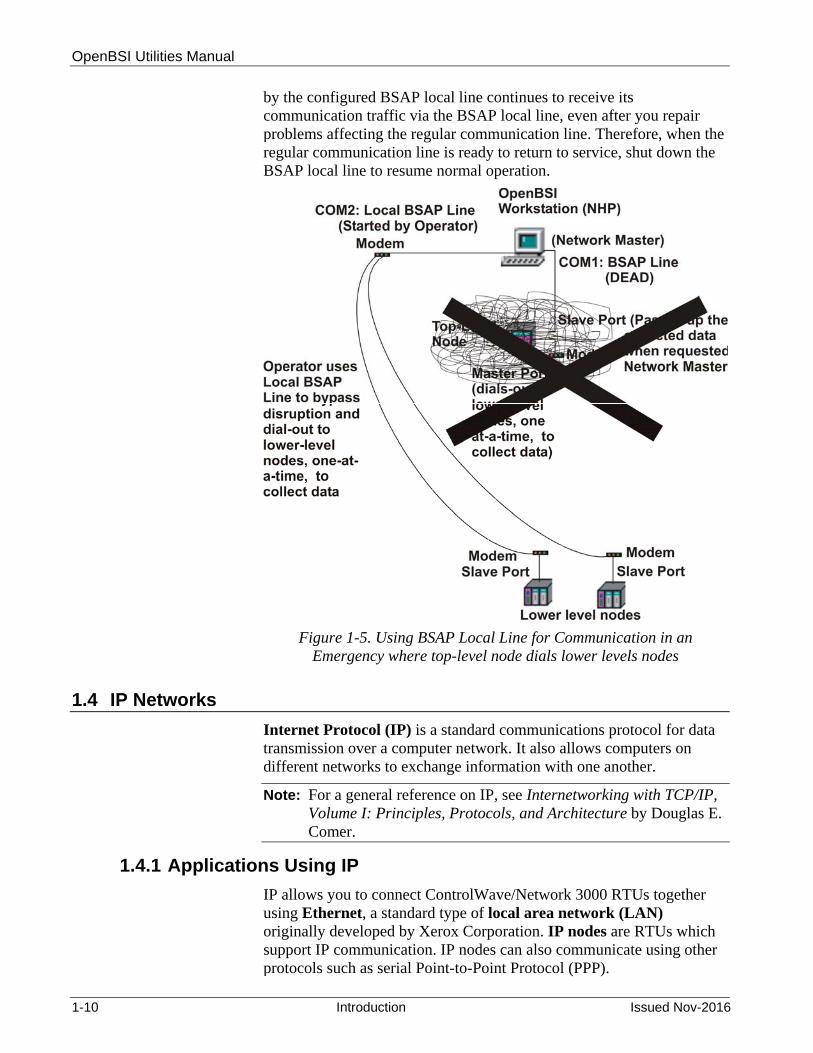
OpenBSI Utilities Manual
1-10 Introduction Issued Nov-2016
by the configured BSAP local line continues to receive its communication traffic via the BSAP local line, even after you repair problems affecting the regular communication line. Therefore, when the regular communication line is ready to return to service, shut down the BSAP local line to resume normal operation.
Figure 1-5. Using BSAP Local Line for Communication in an Emergency where top-level node dials lower levels nodes
1.4 IP Networks
Internet Protocol (IP) is a standard communications protocol for data transmission over a computer network. It also allows computers on different networks to exchange information with one another.
Note: For a general reference on IP, see Internetworking with TCP/IP, Volume I: Principles, Protocols, and Architecture by Douglas E. Comer.
1.4.1 Applications Using IP
IP allows you to connect ControlWave/Network 3000 RTUs together using Ethernet, a standard type of local area network (LAN) originally developed by Xerox Corporation. IP nodes are RTUs which support IP communication. IP nodes can also communicate using other protocols such as serial Point-to-Point Protocol (PPP).
OpenBSI Utilities Manual
Issued Nov-2016 Introduction 1-11
Warning We are discussing the Internet Protocol (IP) for use in communication between ControlWave or Network 3000 RTUs. The normal, intended application is for a “closed circuit” internet (LAN) of RTUs and workstations in a company plant or industrial site.
While, there is no built-in restriction against connecting an IP network of these nodes to the world-wide Internet, remember that any external IP connection (no matter what brand of RTUs and software you use) poses potential risks.
Always change default passwords, as well as default UDP/TCP socket numbers, to lessen the possibility that an unauthorized person could access your internal company process control data.
While these security features help prevent accidental access by plant personnel, do not consider them protection against intentional malicious activity by a sophisticated intruder, i.e. professional “hacker”. Consider purchasing commercially-available "firewall" software to gain a further degree of protection against such malicious intrusions.
1.4.2 Differences between IP Nodes and Other RTUs
From the user's point of view, IP nodes differ primarily in the configuration required for communications. In Network 3000 RTUs, for example, you must configure an IP port inside the ACCOL load. You configure characteristics of the port (baud rate, stop bits, etc.) using the Flash Configuration Utility.
In LocalView you assign an IP address for each IP port on the IP node. (We’ll discuss IP addresses in more detail, later.)
Networks using only IP nodes are somewhat different from standard BSAP networks. There is no hierarchical structure enforced at the network level. For certain applications, this has significant advantages over BSAP, because all nodes in a given section of the network exist on the same level; this simplifies peer-to-peer communication because you don’t need more than a single pair of IP_Client / IP_Server modules to get a message from one node to any other node because all nodes are “siblings” on the same level (see Figure 1-6.)
Note: There is no concept of “polling” in IP networks.
Network Definition Files (NETDEF) at the Network Host PC (NHP) hold Information on the IP addresses for a given section of the network. You use NetView to create the NETDEF files.

OpenBSI Utilities Manual
1-12 Introduction Issued Nov-2016
Figure 1-6. Typical IP Network Using Ethernet
If an IP node or an OpenBSI workstation needs to communicate with another IP node or OpenBSI workstation, and it doesn't know the address of the IP port for that node or workstation, it obtains the necessary addresses and routing information from the NETDEF files at the NHP.
1.4.3 Controllers That Support IP
The ControlWave series and two Network 3000-series RTUs (the 386EX Protected Mode DPC 3330 and DPC 3335 controllers with PES03 / PEX03 or newer firmware and Ethernet hardware) support IP.
In addition to Ethernet, ControlWave controllers support serial IP communications using the Point-to-Point Protocol (PPP).

OpenBSI Utilities Manual
Issued Nov-2016 Introduction 1-13
Format of IP Addresses
Each network connection from an IP node has a unique IP address within the network. Remember that the system associates the IP address with the network connection (IP port) on the node, not the node itself. This potentially allows a single IP node more than one IP port, and consequently, more than one IP address.
IP addresses consist of 32 bits (1's and 0's) divided up into 4 groups of 8 bits each. A period separates each group. You convert each group of 8 bits from binary to a decimal number from 0 to 255 (see ). The resulting IP address is in dotted decimal notation.
Figure 1-7. IP Address Explanation
Each of the numbers in the address has a specific meaning. For our purposes, the IP address consists of a common network portion for each node in the network, and a unique local portion for each particularnode.
Meaning of IP Address Components
Assign addresses to be consistent with whatever conventions you establish for your system. In addition, you must follow certain rules for defining addresses – we discuss these later in this chapter.
You use the sub-net mask to define the specific meaning of each part of the address. The sub-net mask consists of another set of 32 bits (which you must convert to dotted decimal notation). Each bit in the sub-net mask corresponds to a bit in the IP address. If you set a bit in the sub-net mask to 1 (ON), then we assume the corresponding bit in the IP addressis part of the network portion of the IP address. The system ignores (or “masks”) the network portion when it communicates to nodes within the same network, because by definition, the network portions of the addresses for all nodes in the same network are identical. We assume any bit in the sub-net mask which is 0 (OFF) is part of the local addressing scheme.
Figure 1-8 shows the IP address and corresponding sub-net mask for an IP address of 120.0.210.1 and a sub-net mask of 255.0.0.0.

OpenBSI Utilities Manual
1-14 Introduction Issued Nov-2016
Figure 1-8. Sub-net Mask Explanation
Once again, a “1” in the sub-net mask indicates that the corresponding bit in the IP address bit belongs to the network portion of the address. Because the first part of the IP address “01111000”. has a corresponding sub-net mask of “11111111'”we know that “01111000” (120 in decimal) is the network portion of the address.
The remaining parts of the IP address “00000000.11010010.00000001” have a corresponding sub-net mask of “00000000.00000000.00000000”. These bits belong to the local portion of the address.
Rules for Local Addressing Schemes
When you create your IP address, the network portion of the address must appear first. For example, if the network portion is 200, you cannot define an IP address as 0.200.14.1. The network portion must appear first. This means that when you create the sub-net mask, the masked portion (i.e. all 1's) must appear first. The organization of the remaining bits follows any local communications scheme you choose to devise, except that each group of bits that represents something must be contiguous. For example, let's say you “mask out” the first 16 bits to define the network address, i.e. your sub-net mask is: 11111111 . 11111111 . 00000000 . 00000000 which in dotted decimal format is: 255 . 255 . 0 . 0 That leaves 16 bits (indicated by the 0's) for your local communications scheme.

OpenBSI Utilities Manual
Issued Nov-2016 Introduction 1-15
You might want to use the first eight bits to indicate a section or area number for a section of your network. Eight bits allows you to define up to 256 sections. You can use another 8 bits (remaining out of the 16 available) to indicate a node number, allowing up to 256 IP RTUs and OpenBSI workstations in a given section (see Figure 1-9).
Figure 1-9. Sample IP Addressing Scheme
If you have a device (controller, or workstation) which will have multiple IP ports, we recommend you exercise special care when specifying the IP address and mask for each IP port to ensure that IP communication functions according to your plan. For example, you typically would want each IP port to sit on a unique IP network. This is because having two or more IP ports of the same device on the same network is not particularly useful, since only one of the ports will be allowed to send messages out to the network; the other ports will only be able to receive messages.
Sub-net masks determine which nodes are reachable from a given node
The previous sections cover the mechanics of creating IP addresses and sub-net masks. Another aspect we must discuss is the importance of IP addresses and subnet masks.
The IP address and sub-net mask defines the range of acceptable addresses with which the node potentially communicates. For example, if one node’s IP address is 4.3.2.1 and another node’s IP address is 100.100.0.1, there is no common network portion between the two addresses. For that reason, these two nodes cannot communicate with each other directly; they belong to different networks. Any messages between these nodes must pass through one or more router computers.
For two nodes to communicate directly, the network portion of their addresses (specified by the sub-net mask) must match exactly.
To illustrate this concept, look at Figure 1-10. The network shown has one Network Host PC (NHP) called NHP1, and three RTUs named OAK_STREET, ELM_STREET, AND WALNUT_AVE.

OpenBSI Utilities Manual
1-16 Introduction Issued Nov-2016
Figure 1-10. IP Network with Error in Sub-net Masks
Table 1-2, however, reveals a problem with the configured sub-net masks.
Table 1-2. Explanations of IP Addresses and Masks
Node Name IP Address, Sub-net Mask Mask Says This Node Can Send Messages to All Nodes with These Addresses
NHP1 IP ADR: 100.22.49.1 MASK: 255.255.255.0
100.22.49.yyy where yyy is an integer from 0 to 255.
WALNUT_AVE IP ADR: 100.22.49.178 MASK: 255.255.0.0
100.22.yyy.zzz where yyy and zzz are integers from 0 to 255.
OAK_STREET IP ADR: 100.22.50.33 MASK: 255.255.0.0
100.22.yyy.zzz where yyy and zzz are integers from 0 to 255.
ELM_STREET IP ADR: 100.22.51.14 MASK: 255.255.0.0
100.22.yyy.zzz where yyy and zzz are integers from 0 to 255.
SW1-5 IP ADR: 100.22.49.1 MASK: 255.255.255.0
100.22.49.yyy where yyy is an integer from 0 to 255.
SW1-6 IP ADR: 100.22.49.178 MASK: 255.255.0.0
100.22.yyy.zzz where yyy and zzz are integers from 0 to 255.
SW1-7 IP ADR: 100.22.50.33 MASK: 255.255.0.0
100.22.yyy.zzz where yyy and zzz are integers from 0 to 255.
SW1-8 IP ADR: 100.22.51.14 MASK: 255.255.0.0
100.22.yyy.zzz where yyy and zzz are integers from 0 to 255.
SW1-9 IP ADR: 100.22.49.1 MASK: 255.255.255.0
100.22.49.yyy where yyy is an integer from 0 to 255.

OpenBSI Utilities Manual
Issued Nov-2016 Introduction 1-17
Node Name IP Address, Sub-net Mask Mask Says This Node Can Send Messages to All Nodes with These Addresses
SW1-10 IP ADR: 100.22.49.178 MASK: 255.255.0.0
100.22.yyy.zzz where yyy and zzz are integers from 0 to 255.
Based on their specified IP addresses and sub-net masks, OAK_STREET, ELM_STREET, and WALNUT_AVE can all communicate with each other. They can also send messages to NHP1.
There is a problem, however. NHP1’s sub-net mask specifies that it can only send messages to nodes with addresses 100.22.49.nnn where nnn is an integer from 0 to 255. Therefore, the only node it can send messages to is WALNUT_AVE.
To remedy this situation, we need to change NHP1's sub-net mask to 255.255.0.0 so that it can also send messages to OAK_STREET and ELM_STREET. See the corrected sub-net mask in Figure 1-11.
Figure 1-11. IP Network with Corrected Sub-net Mask
1.4.4 Guidelines for Choosing Addresses in a Private Network
If you have a small network which you don’t plan to connect to the world-wide Internet, your choice of IP addresses is largely unrestricted. Even if you have no plans to connect your network to the global Internet, however, the Internet Engineering Task Force recommends, as per RFC 1918 (http://www.ietf.org/rfc/rfc1918.txt) that you assign IP addresses for your private networks from the following ranges:
10.0.0.0 to 10.255.255.255

OpenBSI Utilities Manual
1-18 Introduction Issued Nov-2016
172.16.0.0 to 172.31.255.255 192.168.0.0 to 192.168.255.255 Internet governing bodies set aside these particular ranges of Internet addresses for private networks. Most Internet Service Providers (ISP) recognize any messages coming from these addresses as messages from private networks, and the ISPs filter them out. This helps avoid addressing conflicts should an accidental connection occur between a private network, and the global Internet.
Devices (e.g. RTUs, workstations) in our networks always use fixed IP addresses. This causes certain complexities if you choose to use Dynamic Host Configuration Protocol (DHCP) in your network. Because DHCP assigns IP addresses dynamically, as needed, you must examine your DHCP server to determine the addresses assigned for each RTU or workstation, and then manually enter those addresses in NetView. You should then specify the longest possible lease time for the addresses, to help prevent the loss of a given address through a device failure.
We also strongly recommend you configure the DHCP server to permanently reserve the addresses for the RTUs. (To do this, associate the addresses with RTU MAC addresses within the DHCP configuration or use a totally different address range). Do the same when you configure RAS servers or other machines designed to provide dynamic addressing information. Otherwise, you might accidently use duplicate IP addresses on your network.
1.4.5 IP Network Variations – Connecting Two Networks with a Single Router
Figure 1-12 shows a typical OpenBSI network using IP. A Network Host PC (NHP) and additional OpenBSI workstations sit on the same network as the RTUs (IP nodes). They exist on the same sub-network, and the addresses of all of the devices share the same range of IP addresses.

OpenBSI Utilities Manual
Issued Nov-2016 Introduction 1-19
Figure 1-12. Typical IP Network Using Ethernet
For small networks of up to a few hundred nodes this type of configuration is fine. More complex network configurations are possible, however. When you need many hundreds or even thousands of nodes, or nodes in different geographical locations, the type of configuration, shown above, may prove inadequate.
You may find yourself in a situation where, because of new system requirements, devices on a self-contained existing network now need to share data with devices from an entirely different network.
Imagine, for example, a natural gas field (Figure 1-13) with hundreds of different RTUs and workstations that uses an address range beginning with 10.87.1.x. which now, because of changing requirements, must share data with another natural gas field full of controllers and workstations. This other network, in a different location, uses an address range beginning with 172.24.x.x. Because their current address ranges are incompatible, you cannot easily combine these two networks into a single network.
It might be impractical to try to assign new IP addresses to one group or the other; - - there might not even be enough unused addresses available for you to do that, or the man-hours required to physically re-program the devices might be prohibitive.

OpenBSI Utilities Manual
1-20 Introduction Issued Nov-2016
Figure 1-13. Two Separate IP Networks That Cannot Communicate with Each Other
You use a device called a router (also known as a gateway) in these sorts of situations. See Figure 1-14.

OpenBSI Utilities Manual
Issued Nov-2016 Introduction 1-21
Figure 1-14. Connecting Two Separate IP Networks with a Router
A router is a device which has multiple IP ports such that the router belongs to more than one network. As part of each network, it takes messages from devices in one network and routes them to devices in another network. Typically, a router is a physical hardware device specifically designed for message routing. Software implementations of routers also exist.
Note: Because IP RTUs such as the DPC 3330, and ControlWave can contain more than one IP port (and so can sit on more than one network) the RTUs can actually serve as routers.
In our IP networks, one way you can specify a router is to designate it as the default gateway. When you define a particular IP network, the system automatically sends any message with a destination IP address which lies outside the defined address range for that network to the default gateway, i.e. the router. You define the default gateway from the IP Parameters tab of the Flash Configuration utility.

OpenBSI Utilities Manual
1-22 Introduction Issued Nov-2016
Figure 1-15 shows how to specify the default gateway address for Network "A" and Network "B" controllers, respectively, in our example. Both networks actually use the same device with two different IP ports (one RTU sits on each of the two networks).
Default Gateway (G/W) is an address where any message that cannot be routed within the network will be sent. All controllers in Network “A” have this as their default gateway.
All controllers in Network “B” have this as their default gateway
Figure 1-15. Defining an RTU as a Router
1.4.6 IP Network Variations - Using Multiple Routers (Gateways) and RIP for a Fault Tolerant Connection
Beginning with ControlWave firmware CWP02.0, you can configure multiple gateways (routers) to communicate using Routing Internet Protocol (RIP). We discuss this subject in Chapter 5 in the description of the IP Routes tab of the Flash Configuration Utility.
1.4.7 IP Network Variations - Using Multiple Routers (Gateways) without RIP
The Routing Internet Protocol (RIP) we discuss in Chapter 5 only works if the PC and all devices that serve as routers on the network can send/receive RIP broadcasts. If they can’t, or, if you want to prevent the network overhead of a protocol like RIP, you must find an alternative method for using multiple routers.
One way you can configure this is through the ROUTE ADD command from the DOS prompt of your PC.
In Figure 1-16, an OpenBSI workstation (PC) only accesses devices in the 10.x.x.x network.

OpenBSI Utilities Manual
Issued Nov-2016 Introduction 1-23
Figure 1-16. Separate Networks that Share a Router
Messages from the OpenBSI workstation cannot reach the other 172.16.x.x and 192.168.x.x networks. You can configure communication using ROUTE ADD because those networks have a connection (using routers) to the same network that the OpenBSI workstation is on. The syntax for the command is:
ROUTE ADD aaa.bbb.ccc.ddd MASK eee.fff.ggg.hhh iii.jjj.kkk.lll
Where: aaa.bbb.ccc.ddd is the destination address range you want to reach eee.fff.ggg.hhh is the IP Mask for that address range
iii.jjj.kkk.lll is the address of the gateway or router which provides a route to that destination.
For the figure, shown earlier, if you enter the following ROUTE ADD commands at the DOS prompt, the PC allows messages traffic from the OpenBSI workstation to the RTUs on the 172.16.x.x and 192.168.x.x networks:
ROUTE ADD 172.16.0.0 MASK 255.255.0.0 10.0.1.200
ROUTE ADD 192.168.0.0 MASK 255.255.0.0 10.0.0.10

OpenBSI Utilities Manual
1-24 Introduction Issued Nov-2016
1.5 IP Network Security Protocols (CHAP and PAP) Used on PPP Links
While not required, we strongly recommend you consider using one of the two supported security protocols (PAP and CHAP) to help prevent unauthorized access to your network by an intruder (hacker). Typically, you should use CHAP since it is more secure.
The PAP and CHAP protocols operate in a client/server arrangement. The ControlWave RTU operates as a CHAP (or PAP) server. Either a ControlWave RTU or an OpenBSI workstation operates as a CHAP (or PAP) client. Any client must always supply a valid username/password combination to gain access to the server.
If the OpenBSI workstation is the client, you enter the username and password directly in response to a login prompt. These must match one of the username / password combinations stored in the ControlWave.
If a ControlWave RTU is the client, use the "Challenge Protocol Default Username" field in the “Ports” page of the Flash Configuration Utility to enter the username. The RTU automatically transmits the username / password text string for that username in response to a login prompt from the server.
Both of these security methods are similar at the user level. The difference is in the underlying operation of the protocols.
1.5.1 Challenge Handshaking Authentication Protocol (CHAP)
The CHAP server (ControlWave) issues an encrypted challenge message (which appears as a normal login prompt) to any CHAP client (workstation or ControlWave) that requests access. CHAP encrypts the supplied username and password according to a pre-defined secret encryption key. The result is called the response message.
Even though the username / password combination for a particular user does NOT change on each login attempt, the encrypted challenge and response messages are different on each attempt. This helps prevent an intruder from replicating the proper response message for a given challenge message, either through trial and error or “brute force” searches of all possible challenge messages.
Another characteristic of CHAP is that even after the client logs in, subsequent challenge / response transactions occur to verify that the connection is still with a valid user.

OpenBSI Utilities Manual
Issued Nov-2016 Introduction 1-25
Example 1 - In this first CHAP example, the CHAP client is a PC workstation, and the CHAP Server is a ControlWave RTU.
Figure 1-17. CHAP – Workstation to Controller

OpenBSI Utilities Manual
1-26 Introduction Issued Nov-2016
Example 2 - The second CHAP example is very similar, except in this case, the CHAP client is another ControlWave RTU. For this reason, you configure a username/password combination (default IP user) and store it in FLASH memory. You also configure a Challenge Protocol Default Username on the IP parameters page of the Flash Configuration Utility, to reference the default IP user.
Figure 1-18. CHAP – Controller to Controller

OpenBSI Utilities Manual
Issued Nov-2016 Introduction 1-27
1.5.2 Password Authentication Protocol (PAP)
PAP requires a client requesting access to provide a username and password, similar to CHAP. PAP is a simpler method of protection, however, that has certain characteristics which make it less secure than CHAP.
PAP allows clients to send passwords as clear “plain text” unencrypted strings of characters. This could allow an unauthorized person to intercept a password message, and then subsequently use the password to gain access.
PAP also has no safeguards against repeated attempts to log in. For example, an intruder using trial and error to “guess” a password, or someone using software which performs a “brute force” search of all possible passwords could gain access.
Example 1 - In the first PAP example, the PAP client is a PC workstation, and the PAP Server is a ControlWave RTU.
Figure 1-19. PAP – Workstation to Controller

OpenBSI Utilities Manual
1-28 Introduction Issued Nov-2016
Example 2 - The second PAP example is very similar, except in this case, the PAP client is another ControlWave RTU. For this reason, you configure a username/password combination (default IP user) and store it in FLASH memory. You also configure a Challenge Protocol Default Username, on the IP parameters page of the Flash Configuration Utility, to reference the default IP user.
Figure 1-20. PAP – Controller to Controller
Further Information For further information on PAP and CHAP, see these documents, both of which are available at www.ietf.org.
PPP Authentication Protocols by Brian Lloyd and William Simpson, Daydreamer Computer Systems Consulting Services, RFC 1334, October, 1992.
The MD5 Message-Digest Algorithm by Ronald Rivest, MIT Laboratory for Computer Science, and RSA Data Security Inc., RFC 1321, April, 1992.

OpenBSI Utilities Manual
Issued Nov-2016 Introduction 1-29
1.6 Mixed Networks (Both BSAP and IP nodes)
You can configure multiple IP networks for any Network Host PC (NHP). In addition to IP network(s), you can also define multiple BSAP networks, immediately below the NHP. The NHP serves as the BSAP network master computer.
You can also create a BSAP sub-network underneath an IP node. In this case, the IP node must be the only BSAP Level 1 node, and the NHP is still the Network Master.
These configurations are useful, for example, if you want to add some IP RTUs to an existing network of BSAP nodes.
Figure 1-21 shows a typical configuration which mixes both IP nodes and BSAP network(s). The BSAP node shown on the left hand side, under the IP node, is a small BSAP sub-network which includes only one node. The large grouping of BSAP nodes on the right is a BSAP network.
Figure 1-21. Mixed Network – IP and BSAP

This page is intentionally left blank

OpenBSI Utilities Manual
Issued Nov-2016 Installation 2-1
Chapter 2 – Installing OpenBSI
This chapter discusses the hardware and software requirements for OpenBSI installation, installation instructions, and software registration.
In This Chapter
2.1 Hardware and Software Requirements ..................................................... 2-2 2.1.1 Controllers used with OpenBSI ................................................. 2-2 2.1.2 Recommended Hardware/Software for the OpenBSI Workstation:
................................................................................................... 2-2 2.2 Installing the OpenBSI Utilities .................................................................. 2-3 2.3 Registering Your Software ....................................................................... 2-10
2.3.1 How do I Register My Software? ............................................. 2-10 2.4 How to Transfer a License from One PC to another PC ......................... 2-17
2.4.1 Using the software… ............................................................... 2-22 2.5 Using OpenBSI with Newer Microsoft® Windows Operating Systems ... 2-22
2.5.1 Which OpenBSI Features are affected? ................................. 2-23 2.5.2 How do I make these applications work properly with Windows?2-23 What is a Firewall? ............................................................................. 2-23
2.6 Using OpenBSI with Microsoft® Windows XP Service Pack 2 ............... 2-24 2.6.1 Reconfiguring the Windows XP Firewall ................................. 2-24 2.6.2 Disabling the Windows XP Firewall ......................................... 2-24 2.6.3 Making Object Server an Exception to the Windows XP Firewall2-24 2.6.4 Add Ports for DCOM and RTRSERVC for the XP firewall ...... 2-26 2.6.5 Add Ports for the Bristol IP Driver (BSIPDRV) for the XP firewall2-28 2.6.6 Reconfiguring the DCOM Software for the XP firewall ........... 2-29
2.7 Using OpenBSI with Microsoft® Windows 2008 Server .......................... 2-34 2.7.1 Reconfiguring the Windows 2008 Server Firewall .................. 2-34 2.7.2 Disabling the Windows 2008 Server Firewall .......................... 2-34 2.7.3 Making Object Server an Exception to the Windows 2008 Server
Firewall .................................................................................... 2-35 2.7.4 Add Ports for DCOM and RTRSERVC for the Windows 2008
Firewall .................................................................................... 2-37 2.7.5 Add Ports for the Bristol IP Driver (BSIPDRV) for the Windows 2008
Server Firewall ........................................................................ 2-39 2.7.6 Reconfiguring the DCOM Software for the Windows 2008 Server
Firewall .................................................................................... 2-41 2.8 Using OpenBSI with Microsoft® Windows 7 ........................................... 2-47
2.8.1 Reconfiguring the Windows 7 Firewall .................................... 2-47 2.8.2 Disabling the Windows 7 Firewall ........................................... 2-47 2.8.3 Making Object Server an Exception to the Windows 7 Firewall2-47 2.8.4 Add Ports for DCOM and RTRSERVC for the Windows 7 Firewall
................................................................................................. 2-56 2.8.5 Add Ports for the Bristol IP Driver (BSIPDRV) for the Windows 7
Firewall .................................................................................... 2-57 2.8.6 Reconfiguring the DCOM Software for the Windows 7 Firewall2-59
2.9 Using OpenBSI with Microsoft® Windows 10 Professional .................... 2-59 2.9.1 Reconfiguring the Windows 10 Firewall .................................. 2-59 2.9.2 Disabling the Windows 10 Firewall ......................................... 2-59 2.9.3 Making Object Server an Exception to the Windows 10 Firewall2-60 2.9.4 Add Ports for DCOM and RTRSERVC for the Windows 10 Firewall
................................................................................................. 2-67 2.9.5 Add Ports for the Bristol IP Driver (BSIPDRV) for the Windows 10
Firewall .................................................................................... 2-68 2.9.6 Reconfiguring the DCOM Software for the Windows 10 Firewall2-70
2.10 Using OpenBSI with Microsoft® Windows 2012 Server .......................... 2-70

OpenBSI Utilities Manual
2-2 Installation Issued Nov-2016
2.10.1 Reconfiguring the Windows 2012 Server Firewall .................. 2-70 2.10.2 Disabling the Windows 2012 Server Firewall .......................... 2-70 2.10.3 Making Object Server an Exception to the Windows 2012 Server
Firewall .................................................................................... 2-71 2.10.4 Add Ports for DCOM and RTRSERVC for the Windows 2012 Server
Firewall .................................................................................... 2-80 2.10.5 Add Ports for the Bristol IP Driver (BSIPDRV) for the Windows 2012
Server Firewall ........................................................................ 2-81 2.10.6 Reconfiguring the DCOM Software for the Windows 2012 Server
Firewall .................................................................................... 2-83 2.11 Recommendations for Using OpenBSI ActiveX Controls ........................ 2-83
2.1 Hardware and Software Requirements
OpenBSI requires a suitable PC workstation, and collects data from ControlWave and/or Network 3000 controllers.
2.1.1 Controllers used with OpenBSI
OpenBSI requires a network of ControlWave and/or Network 3000-series controllers (RTUs). OpenBSI functions with any ControlWave RTUs as well as any Network 3000 RTU with released firmware created after 1994.
2.1.2 Recommended Hardware/Software for the OpenBSI Workstation:
To run OpenBSI, your PC workstation must meet the following minimum system requirements:
1 GHz processor at least 200 MB free disk space for use by OpenBSI 512 MB RAM (more recommended) CD-ROM drive VGA Monitor (minimum 256 colors 800x600). Optimal screen
resolution for OpenBSI web pages is 1024 x 768. Mouse Communication cable(s) to connect the PC to the RTU network Microsoft® Windows® 2008 Server, Windows® 7.0 Professional,
Windows® 10 Professional, or Windows® 2012 Server. OpenBSI supports both 32-bit and 64-bit operating systems. We recommend you install the latest available service pack for your operating system.
Microsoft® Windows® 7.0 Enterprise is not supported. Note: Emerson only tests OpenBSI on the following platforms:
Windows 7.0 Professional, Windows 10 Professional, and Windows™ 2008 Server including both dual core, and dual-core dual-processor computers.
Microsoft® Internet Explorer Version 5 or newer (Required for ControlWave web pages).

OpenBSI Utilities Manual
Issued Nov-2016 Installation 2-3
Note: For older OpenBSI versions, if you use Microsoft® Windows XP Service Pack 2 (or newer), you must change default operating system settings for certain OpenBSI features to work. Please see the Using OpenBSI with Microsoft® Windows XP Service Pack 2 notes at the end of this chapter for details.
2.2 Installing the OpenBSI Utilities
We recommend you shut down all other programs before you begin to install OpenBSI. OpenBSI includes several different packages – which packages you choose to install depends on your application. You must register some packages to continue using them after the 60-day trial period expires.
Caution If you install over an existing version of OpenBSI, and you previously added other programs or data to the default OpenBSI installation folder (\Program Files\Bristol\OpenBSI\) or its sub-folders (ControlWave projects, Sixnet I/O definitions, etc.) you must back them up prior to the OpenBSI installation. If you install OpenBSI Network Edition over an existing version of OpenBSI, data in the \OpenBSI folder is automatically copied to the user files area. The original data is left untouched. The default user files area is \ProgramData\Bristol\OpenBSI. Note: Windows normally hides this folder. If you install BSI_Config over an existing version of BSI_Config, the installation leaves existing data files in the \OpenBSI area untouched and BSI_Config continues to use the existing \OpenBSI area for new data files. You cannot install OpenBSI Network Edition or BSI_Config on the same PC as Field Tools software versions prior to 2.0. Field Tools version 2.0 (and newer) can coexist on the same PC with OpenBSI Network Edition or BSI_Config. You also cannot install OpenBSI Network Edition or BSI_Config on the same PC with OpenEnterprise Version 3.1 or newer. Beginning with OpenBSI 5.8, the older OPC Server is not supported; use Object Server instead. Once you install OpenBSI 5.8, any older version of OPC Server on your PC ceases to function. If you install OpenBSI on a different drive from a previous installation, you must uninstall the previous version and edit the Windows system path statement to remove the previous OpenBSI path reference, before you install the new version. If you use OpenBSI utilities in conjunction with a third-party human-machine interface (HMI) package, you must remove any version of the file BSI32.DLL from the installation directory of the third-party package, and replace it with the newer version from the OpenBSI installation directory. If you don’t remove the older version, OpenBSI will function improperly. Although not recommended, if you install OpenBSI and the third-party package in the same installation directory, install OpenBSI after the third-party package to solve the BSI32.DLL problem.
You cannot install ControlWave Designer on the same PC on which you have installed other KW products (for example MULTIPROG or another product which incorporates MULTIPROG) or else you may encounter

OpenBSI Utilities Manual
2-4 Installation Issued Nov-2016
licensing issues or other problems.
Please review the release notes (README.DOC, README.TXT) for any late changes not included in this manual.
1. Log into the workstation with administrative privileges.
2. Insert the OpenBSI CD-ROM in your CD-ROM drive.
3. If your CD-ROM drive has autorun enabled, skip to the next step. Otherwise, open a DOS prompt with administrative privileges, then set the folder to the CD root directory, and run the same “open” command that is in the autorun.inf file on the CD, for example “demo32.exe openbsi.dbd”. When the CD browser screen appears, choose the Install OpenBSI option.
4. A screen reminds you to close all other programs, and warns you that older OpenBSI versions will be removed. Click Next. (See Figure 2-1.)
Figure 2-1. OpenBSI Installer - Welcome Screen
5. A license agreement screen opens (Figure 2-2). Review the agreement, using the scroll bar to bring it into view. Click I accept the terms of the license agreement to proceed. Then click Next.
Click Next

OpenBSI Utilities Manual
Issued Nov-2016 Installation 2-5
Figure 2-2. OpenBSI Installer - License Agreement
6. On the next screen (Figure 2-3), you can specify the user files folder. The system stores user files such as ControlWave projects, ACCOL files, recipes, and network files in sub-folders of this folder. Note: If User Account Control (UAC) is enabled in Windows, you must have modify access to this folder. The default is C:\ProgramData\Bristol\Openbsi. Use the default or use Browse to specify a different user files folder. When finished click Next.
Note: You can use the OpenBSI Folders tab of the Advanced Configuration tool to view/change the names of sub-folders of the OpenBSI user files folder. See Appendix E for details.
Figure 2-3. OpenBSI Installer – User File Folders
Click here, then click Next
Click Next

OpenBSI Utilities Manual
2-6 Installation Issued Nov-2016
7. On the next screen, use the check-boxes to select whichever package(s) you want to install.
Figure 2-4. OpenBSI Installer - Choose Packages
Table 2-1. OpenBSI Packages
Software Component Description
Network Edition:
NetView You use NetView to configure the OpenBSI Workstation and start OpenBSI communications. This selection also installs several other tools including LocalView, DataView, Alarm Router, BSAP to IP Redirector, Remote Communication Statistics Tool, Data Array Utility, ACCOL and 1131 Downloaders, Off-Line Database Configuration utility, Signal Extractor, Signal Writer, OpenBSI DDE Server, ValScan, ActiveX Controls, Web_BSI web pages.
Harvester You use the programs in this package to collect array / archive and audit trail data, and export it to data files. This package includes the OpenBSI Harvester and the Data File Conversion Utility. For information on the Harvester software see the OpenBSI Harvester Manual (document# D5120). NOTE: In order to use the Harvester, you must also install NetView.
Programming Software:
ACCOL Workbench Lets you create, edit, and debug ACCOL files used in a Network 3000 series RTU. See the ACCOL Workbench User’s Manual (document# D4051) for details. In addition, the ACCOL Downloader and LocalView programs are included.
ControlWave Designer with ACCOL III
This software lets you create, edit, and debug IEC 61131 projects for the ControlWave RTU. For information on using ControlWave Designer, see Getting Started with ControlWave Designer(document# D5085). This selection also includes the ACCOL III Function Block Library, ACCOL Translator, and the IEC 61131 Downloader.

OpenBSI Utilities Manual
Issued Nov-2016 Installation 2-7
Virtual ControlWave The Virtual ControlWave includes a set of tools that
allows you to take real-time signals from the OpenEnterprise Database and bring them into a ControlWave Designer project. Once in ControlWave Designer, you can create calculations using those signals. Then you compile and download the project into the Virtual ControlWave, where it runs like any other project. The Virtual ControlWave then stores results of the calculations back in the OpenEnterprise Database.
Security Vision The Security Vision application is a package of hardware and software which allows a ControlWave RTU to store images from a remote security camera, and make them available to operators back at the OpenBSI Workstation.
Setup and Configuration Utilities:
BSIConfig This free package includes web pages necessary for calibration and configuration of the 3530-series of TeleFlow flow computers, correctors and recorders, as well as the 3808 MVT Transmitter and the 4088B.It also includes LocalView, Diagnostics, WINUOI, and the ControlView file viewer utility. IMPORTANT: You cannot install the standalone version of BSIConfig on a PC that already has OpenBSI Network Edition installed.
Remote I/O Tools This package installs I/O Tools for configuring ControlWave Ethernet I/O. See the on-line help in the Remote I/O Toolkit for information on how to use the Remote I/O Tools.
Communications Interfaces for Non-OE Users:
ObjectServer The ObjectServer suite works with OpenBSI to provide OPC clients (such as an HMI package) with real-time access to a network of ControlWave/Network 3000 RTUs.
ObjectServer Database This uses OpenBSI communications to collect real-time and alarm data from the RTU network and store it in a database.
ObjectServer Client This transfers data between the ObjectServer database and a third-party HMI that serves as an OPC client.
WebToolkit This consists of a set of tools that allow you to create a simple HMI using web pages. This HMI retrieves and displays data from ObjectServer.
8. Once you make your choices, click Next.

OpenBSI Utilities Manual
2-8 Installation Issued Nov-2016
9. This is your last opportunity to make any changes prior to starting the installation. If you want to make changes, you can click Back to go back to earlier pages. If you want to read the printed release notes for this version of OpenBSI, check the View the Release Notes box. (See Figure 2-5.)
10. If you are ready to perform the installation, click Install, and the installation process starts. Be patient, as it may take several minutes to install all of the different utilities, depending upon which you choose.
Figure 2-5. OpenBSI Installer – Ready to Install
11. When the installation completes, re-boot your computer when
prompted (see Figure 2-6). This must be done in order for OpenBSI to function properly. If you choose not to re-boot now, you must do so before running OpenBSI. Click Finish, and the installation will be complete, and re-boot will proceed, if you chose to do it now.
Click Install

OpenBSI Utilities Manual
Issued Nov-2016 Installation 2-9
Figure 2-6. OpenBSI Installer – Installation Finished
After re-boot, an “OpenBSI Tools” menu selection is added to your Windows Start Programs menu through which you can access the various OpenBSI utilities. If you prefer, you can create Windows™ shortcuts to the tools to provide access through icons on the desktop. See your Windows™ documentation for information on how to do this.
Click Finish

OpenBSI Utilities Manual
2-10 Installation Issued Nov-2016
2.3 Registering Your Software
Upon initial installation, the OpenBSI software packages operate for a 60 day evaluation period. Each time you start the software the system displays a reminder message telling you that the software is not registered (see Figure 2-7), and shows you a count of the number of days remaining in the trial period. During this trial period, you can continue to run the software without registering by clicking OK.
Caution At the conclusion of the 60-day evaluation period, the OpenBSI software packages cease to function. You MUST register the software packages in order to use them after 60 days. Do NOT attempt to set back the date on your computer in order to extend the evaluation period; doing so disables the software and terminates the evaluation period.
Figure 2-7. Software Not Registered Message
2.3.1 How do I Register My Software?
1. Install the desired software package(s) on your computer as described in Section 2.2. The computer must have an active Internet connection.
Note: If this computer does not have an active Internet connection, you will need access to a computer which does, and you will need a USB thumb drive (or other method) to transfer the license file between the Internet-connected computer, and the computer on which you have installed the software.
2. Start the License Manager software, on the computer containing the newly installed software packages, using the sequence: Start > Programs > Bristol Babcock Licensing> License Manager.
3. The License Manager examines your PC, and identifies in a list, which OpenBSI software packages are installed on this computer (see Figure 2-8). Any package that is not registered shows as Trial in the State field. Click Create LRF to generate a License Request File (*.LRF) and save the file on your PC. Leave the License Manager session running.
Note: Make note of where on this computer you save the LRF file, because you will need it later.
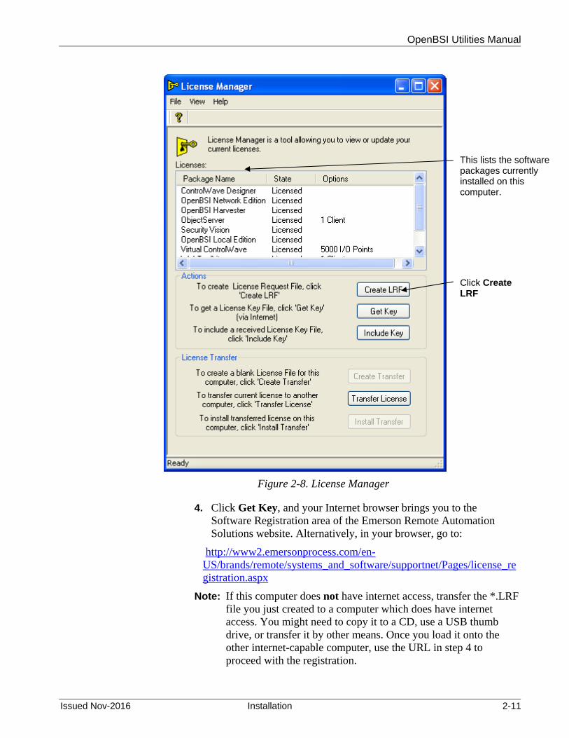
OpenBSI Utilities Manual
Issued Nov-2016 Installation 2-11
Figure 2-8. License Manager
4. Click Get Key, and your Internet browser brings you to the Software Registration area of the Emerson Remote Automation Solutions website. Alternatively, in your browser, go to:
http://www2.emersonprocess.com/en-US/brands/remote/systems_and_software/supportnet/Pages/license_registration.aspx
Note: If this computer does not have internet access, transfer the *.LRF file you just created to a computer which does have internet access. You might need to copy it to a CD, use a USB thumb drive, or transfer it by other means. Once you load it onto the other internet-capable computer, use the URL in step 4 to proceed with the registration.
Click Create LRF
This lists the software packages currently installed on this computer.

OpenBSI Utilities Manual
2-12 Installation Issued Nov-2016
Figure 2-9. Software Registration Page on Website – Initial Appearance
5. Click CLICK HERE TO REGISTER.
Figure 2-10. Software Registration Page on Website – Expanded Appearance
6. Click the Enter your License Id and Password and click Sign-On.
Note: You can find the License Id and Password on a label affixed to the outside of your OpenBSI CD-ROM package.
7. Now you have two options. You can view which licenses have been purchased and are available for you to register, or you can skip that step and proceed to register your software. To view the available licenses, go to step 8. To register the software, skip to step 9.
Note: The Park option shown in Figure 2-11 does not apply to any OpenBSI related products; use the transfer license option instead.

OpenBSI Utilities Manual
Issued Nov-2016 Installation 2-13
Figure 2-11. Register or View Licenses
8. To view which software packages have been purchased for this particular License Id number, as well as how many of those licenses are already in use, click the View link. The View Software Licenses page (Figure 2-12) opens. You may need to use the scroll bar to locate the product you want to view.
Figure 2-12. View Software Licenses Web Page

OpenBSI Utilities Manual
2-14 Installation Issued Nov-2016
Field Description Product Name This displays the name of the software packages for
which licenses have been purchased using your Customer Id number. In addition to OpenBSI packages other software products such as OpenEnterprise packages are displayed.
Available This displays the number of licenses out of the total number purchased which have not been registered for use. If the Available number is 0, you cannot register a new copy of this particular package.
Quantity Ordered This displays the total number of licenses purchased using this Customer Id number.
Clients If the particular package includes restrictions on the number of I/O clients, that appears here.
I/O Points If the particular package includes restrictions on the number of I/O points, that appears here.
9. To register your software, click the Register link. The Registration Information page opens.

OpenBSI Utilities Manual
Issued Nov-2016 Installation 2-15
Figure 2-13. Enter Your Information Web Page
10. Enter your name in the Your Name field, and your e-mail address in both the E-mail Address and Verify E-Mail fields. Enter your mailing address in the Company Address fields then scroll down to specify your Country and specify your preferences about receiving notifications of product updates, service packs, contract renewals, and marketing announcements by e-mail.
11. Then use the Browse button to locate the license request file you generated previously in Step 3. Finally, click Next. The Unlock Software Licenses page opens.
Note: The website will send you an e-mail with an attached unlock key file to the e-mail address you specify here.
12. Click the Unlock checkbox for the product(s) you want to register, then click Submit License Request to send the license request to the website.

OpenBSI Utilities Manual
2-16 Installation Issued Nov-2016
Figure 2-14. Submit License Request Web Page
13. If the license request is successful, the website generates a key file you can use to unlock your software. Click Key file to download a copy of the key file (see Figure 2-15). (The website also e-mails you a copy of the key file at the e-mail address you entered in step 9.)
Note: If the computer which contains the locked software does not have internet access, you need to transfer the key file back to that computer to complete the registration process.
Your unlock request has completed successfully. Please download, save and apply the Key file using the License Manager. Key file A copy of the Key file has also been emailed to (your e-mail address here)
View
Figure 2-15. Download Key File Web Page
14. In order to complete the registration process, the key file you received must reside on the PC containing the newly installed software packages. Go back to the License Manager session you started in Step 3. (If you shut the License Manager down, restart it by clicking Start > Programs > Bristol Babcock Licensing> License Manager.

OpenBSI Utilities Manual
Issued Nov-2016 Installation 2-17
15. To apply the key file, click the Include Key button and specify the location of the key file.
16. If the registration completes successfully, you will see the message box in Figure 2-16; just click OK and you’re done. Reboot your PC for the new licenses to be activated.
Figure 2-16. License Successfully Updated message box
2.4 How to Transfer a License from One PC to another PC
Occasionally, it may be necessary for you to transfer an OpenBSI software license from one computer, to another computer. This might be necessary, for example, if you are upgrading to a newer computer, and want to shift your OpenBSI license to the newer computer, and remove it from the older computer.
In this explanation, the computer which is giving up its license will be referred to as the source computer and the new computer which will receive the transferred license will be referred to as the destination computer.
Note: In order to transfer the license, the license on the source computer must already be registered, and the software must have already been installed on the destination computer.
1. Start the License Manager software, on the destination computer,
using the sequence: Start > Programs > Bristol Babcock Licensing> License Manager.
2. Select the unlicensed package you want to change from a trial / demo package, into a licensed package, and generate an empty transfer request file.
Note: The transfer request file you create must be read-write. It cannot be a read-only file.

OpenBSI Utilities Manual
2-18 Installation Issued Nov-2016
Figure 2-17. Generate a License Transfer Request File
3. Answer Yes to the prompt. (See Figure 2-18.)
Figure 2-18. Confirm Transfer Request message box
4. Save the empty transfer (*.XFR) file. (See Figure 2-19.)
First, select the unlicensed package for which you want to obtain a license for from another computer.
Then click Create Transfer
Click Yes.

OpenBSI Utilities Manual
Issued Nov-2016 Installation 2-19
Figure 2-19. Save Transfer Request File
5. Click OK when the file is created.
Figure 2-20. XFR File Created Successfully
6. Copy the XFR File you just saved onto the source (licensed)
computer. You can transfer it via a USB thumb drive, e-mail, etc.
7. Start the License Manager software, on the destination computer, using the sequence: Start > Programs > Bristol Babcock Licensing> License Manager.
8. Now, you must transfer the license of the software package, into the transfer (*.XFR) file you created in Step 5. In the License Manager, select the license you want to transfer and click Transfer License.
9. Now locate the XFR file you created earlier and click Open.
Click Save to create the empty transfer file.
Click OK.
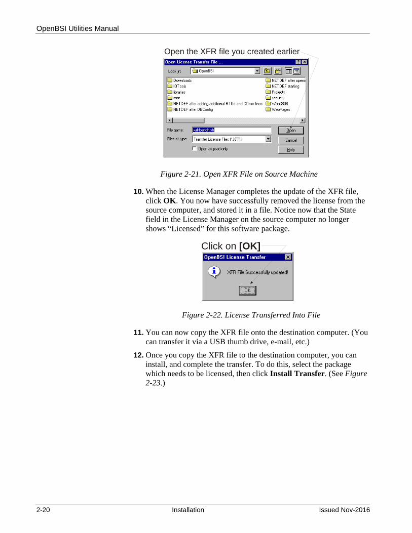
OpenBSI Utilities Manual
2-20 Installation Issued Nov-2016
Click on [OK]
Open the XFR file you created earlier
Figure 2-21. Open XFR File on Source Machine
10. When the License Manager completes the update of the XFR file, click OK. You now have successfully removed the license from the source computer, and stored it in a file. Notice now that the State field in the License Manager on the source computer no longer shows “Licensed” for this software package.
Figure 2-22. License Transferred Into File
11. You can now copy the XFR file onto the destination computer. (You can transfer it via a USB thumb drive, e-mail, etc.)
12. Once you copy the XFR file to the destination computer, you can install, and complete the transfer. To do this, select the package which needs to be licensed, then click Install Transfer. (See Figure 2-23.)

OpenBSI Utilities Manual
Issued Nov-2016 Installation 2-21
Figure 2-23. Install Transferred License
13. The License Manager prompts you to confirm you want to install the transferred license. Click Yes. (See Figure 2-24.)
Figure 2-24. Confirm Transferred License
Select the package you want to license, then click Install Transfer

OpenBSI Utilities Manual
2-22 Installation Issued Nov-2016
14. Specify the location of the updated XFR file on the destination computer and click Open. This completes the transfer.
2.4.1 Using the software…
Most users can begin with one of the “Quickstart” chapters, listed below.
Chapter 3 - Quickstart (OpenBSI BSAP Communication) Chapter 4 - Quickstart (OpenBSI IP Communication)' Detailed information on each option in NetView is included in Chapter 6 - Using NetView.
Information on programming configuration parameters at the controller using the Flash Configuration utility is included in Chapter 5 - Using LocalView.
Once the configuration activities described in these chapters are complete, you can proceed to use the other tools (Downloader, DataView, Signal Writer, etc.) The remaining chapters of this manual describe these tools.
As you are becoming familiar with a particular utility, you should also consult the Help Windows integrated with it. These are accessed from the Help menu bar selection in each individual utility, or by pressing the [F1] key.
Some utilities also include context-sensitive help, in which you point at the item for which you need help. Context-sensitive help is accessible through the icon shown at left.
2.5 Using OpenBSI with Newer Microsoft® Windows Operating Systems
Microsoft® Windows operating systems in recent years (XP and newer) include security enhancements designed to prevent unauthorized communication with other computers. If you have installed these operating systems on your computer, any application which Windows is unfamiliar with, and performs communications, may either be automatically prevented from working, or its operation may be restricted by the Windows operating system.
Like any other communications application, these security enhancements affect OpenBSI. Certain default Windows settings will disable some OpenBSI features. In order to remedy this situation, these OpenBSI application programs need to be identified for Windows, as authorized communicators. Once this is done, OpenBSI is recognized by Windows, and can operate normally.

OpenBSI Utilities Manual
Issued Nov-2016 Installation 2-23
2.5.1 Which OpenBSI Features are affected?
Proxy communication – If your system incorporates proxy OpenBSI Workstations, that is, OpenBSI Workstations that are not Network Host PCs, but that nonetheless communicate with RTUs through other OpenBSI Workstations, they will no longer communicate, either directly, or indirectly.
Bristol IP Driver – BSIPDRV - If your system communicates with controllers using IP, both IP communications and time synchronization messages will be blocked by the firewall.
Object Server - This application uses OPC (OLE for Process Control), an industry-standard communication method which is disabled by the operating system upgrade.
ActiveX Controls– The OpenBSI ActiveX controls (used in web pages, for example) will still operate; however, users are required to perform extra steps to access them following the operating system upgrade. In addition, certain items, such as grid controls for signal lists, etc. may require a particular OpenBSI Service Pack, or Microsoft® Windows patch to work correctly.
2.5.2 How do I make these applications work properly with Windows?
In order for these OpenBSI applications to work properly again, you need to:
Re-configure the Windows Firewall software (if you’re using it). Re-configure the DCOM and RTRSERVC software on your
computer.
What is a Firewall?
A firewall is either a software program or a hardware device, which blocks unauthorized communications. It is used to block malicious communications (spam e-mail, viruses, hacker intrusions, etc.) In order for communications to be allowed through the firewall, they must be authorized. Windows operating systems have a built-in firewall, which, beginning with Windows XP Service Pack 2, is turned ON by default.
What is DCOM?
DCOM stands for Distributed Component Object Model. It’s just acommunication protocol that allows different applications to talk to each other over networks. The Object Server requires DCOM in order to function.
What is RTRSERVC?
RTRSERVC is a router service that allows OpenBSI proxycommunication.

OpenBSI Utilities Manual
2-24 Installation Issued Nov-2016
The next several sections details steps you need to take to allow OpenBSI applications to work with various Windows operating systems.
2.6 Using OpenBSI with Microsoft® Windows XP Service Pack 2
For OpenBSI to function with XP Service Pack 2, you need to re-configure the Windows Firewall software, and re-configure DCOM software.
2.6.1 Reconfiguring the Windows XP Firewall
Reconfiguring the Windows XP Firewall involves either disabling it (not recommended in most cases) or making certain OpenBSI applications exceptions to the firewall, to let them through.
Note: Portions of these sections reproduced, with permission, from the OPC™ Foundation white paper Using OPC via DCOM with Microsoft Windows XP Service Pack 2 by Karl-Heinz Deiretsbacher, Jim Luth, and Rashesh Mody 2004.
Note: If Object Server is currently running, you must shut it down during this configuration.
2.6.2 Disabling the Windows XP Firewall
If the Windows XP Firewall is the only firewall protection you have, we recommend you leave it enabled, and skip to Section 2.6.3. If, however, you have a corporate firewall, already installed, and it is operating correctly, you may decide that the Windows XP Firewall is unnecessary. If this is the case, you can disable the Windows XP firewall.
Caution Only perform these next three steps if you have a separate corporate firewall which renders the XP firewall unnecessary.
1. From the Windows™ Control Panel, double-click on Windows
Firewall.
2. On the General page of the Windows Firewall dialog box, select the Off (not recommended) button, then click on OK.
3. Skip the remaining steps in this sub-section, and continue with the section “Reconfiguring the DCOM Software.”
2.6.3 Making Object Server an Exception to the Windows XP Firewall
If you install Object Server, you need to grant it as an exception to the Windows XP Firewall.

OpenBSI Utilities Manual
Issued Nov-2016 Installation 2-25
1. From the Windows™ Control Panel, double-click Windows Firewall.
2. On the Exceptions tab of the Windows Firewall dialog box, click Add Program (see Figure 2-25.)
Figure 2-25. Windows Firewall Exception tab
3. To add Object Server to the list of authorized communicators through the Windows XP Firewall, choose Object Server’s OPC server (BristolOPCServer.exe) from the list, or use the Browse button to locate it. Select it, and then click OK.
Click Add Program

OpenBSI Utilities Manual
2-26 Installation Issued Nov-2016
Figure 2-26. Windows Firewall Add Program dialog box
2.6.4 Add Ports for DCOM and RTRSERVC for the XP firewall
In the previous section, we specified programs that the Firewall needed to know about. Now we have to identify which ports these programs use.
Note: When we say ports, we’re not talking about physical communication ports; we’re talking about software connections into the system.
To add the ports, follow these steps:
1. From the Exceptions tab of the Windows Firewall dialog box, click Add Port.

OpenBSI Utilities Manual
Issued Nov-2016 Installation 2-27
Figure 2-27. Windows Firewall Add Port
2. First, you need to add the port for DCOM. In the Add Port dialog
box, enter DCOM for the port’s Name, 135 for the Port Number and choose TCP. Then click OK.
Figure 2-28. Windows Firewall Add a Port dialog box
Click Add Port

OpenBSI Utilities Manual
2-28 Installation Issued Nov-2016
3. Now add the port for RTRSERVC. Click Add Port again, and in the Add Port dialog box, enter rtrservc for the port’s Name, 1236 for the Port number and choose TCP. Then click OK.
Note: The reason we say “1236” is that “1236” is the default port number used by RTRSERVC. That number is initially set in the TCP Port Number for Router Process field of the IP Parameters dialog box in NetView’s System Wizard. If you originally set it to something different than 1236, you should use that number here, instead of 1236.
2.6.5 Add Ports for the Bristol IP Driver (BSIPDRV) for the XP firewall
This section is almost identical to Section 2.6.4. We are adding two additional ports for the Bristol IP Driver (BSIPDRV). One is for the driver itself, and the other is for Time Synchronization messages. The main difference from the previous step is the port numbers and the port type, which is UDP, instead of TCP.
1. From the Exceptions tab of the Windows Firewall dialog box, click Add Port.
Figure 2-29. Windows Firewall – Add Port for BSIPDRV
2. Add the first port for BSIPDRV. In the Add Port dialog box, enter
BSIPDRV for the port’s Name, 1234 for the Port Number and choose UDP. Then click OK.
Click Add Port

OpenBSI Utilities Manual
Issued Nov-2016 Installation 2-29
Figure 2-30. Windows Firewall Add Port for BSIPDRV
3. Repeat Step 2 to add the second port for BSIPDRV except enter 1235 for the Port Number.
Note: Again, we’re saying “1234” and “1235” because those are the default port numbers used by BSIPDRV. Those numbers are initially set in the UDP Port Number for IP Driver and UDP Port Number for Time Synch fields of the IP Parameters dialog box in NetView’s System Wizard. If you originally set them to something different than 1234 and 1235, you should use those numbers here, instead.
2.6.6 Reconfiguring the DCOM Software for the XP firewall
You must reconfigure the DCOM software for the Object Server to function correctly.
1. Click Start > Run.
2. Type DCOMCnfg in the Run dialog box and click OK. This opens the Component Services page.

OpenBSI Utilities Manual
2-30 Installation Issued Nov-2016
Type ‘DCOMCnfig’ then click [OK].
First, click on ‘Component Services’
Then -click on the ‘My Computer’ icon,and choose from the pop-upmenu.
right“Properties”
Figure 2-31. Run dialog box
Figure 2-32. Component Services page
3. In the Component Services page, locate Console Root in the file tree of the left window pane.
4. Under Console Root, click Component Services to expand the folder.
5. In the right window pane, right-click the My Computer icon, and select Properties from the pop-up window. This opens the My Computer Properties dialog box.
6. In the My Computer Properties dialog box, click the COM Security tab.

OpenBSI Utilities Manual
Issued Nov-2016 Installation 2-31
Figure 2-33. Access Permissions
7. In the “Access Permissions” box (top part of the page) click Edit Limits.
8. In the Group or user names box (top part of the Access Permissions dialog box) click the ANONYMOUS LOGIN icon.
Click Edit Limits
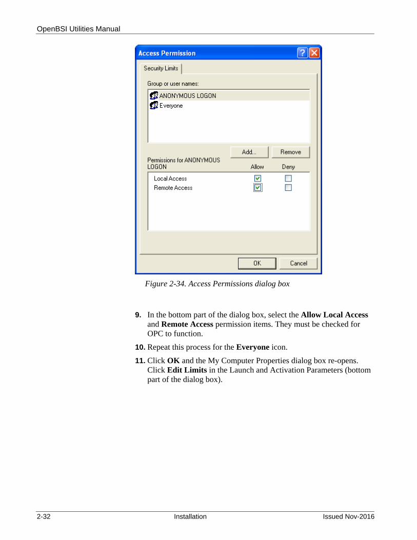
OpenBSI Utilities Manual
2-32 Installation Issued Nov-2016
Figure 2-34. Access Permissions dialog box
9. In the bottom part of the dialog box, select the Allow Local Access and Remote Access permission items. They must be checked for OPC to function.
10. Repeat this process for the Everyone icon.
11. Click OK and the My Computer Properties dialog box re-opens. Click Edit Limits in the Launch and Activation Parameters (bottom part of the dialog box).

OpenBSI Utilities Manual
Issued Nov-2016 Installation 2-33
Figure 2-35. Launch and Activation Permissions
12. In the Launch and Activations Permissions box (bottom part of the My Computer Properties COM Security tab) click Edit Limits.
13. In the Launch Permissions dialog box, click the Everyone icon in the Group or user names box (top part of the dialog box).
Figure 2-36. Launch Permissions dialog box
14. In the bottom part of the dialog box, select the Allow permission
items for all the options shown (Local Launch, Remote Launch, Local Activation, and Remote Activation.). It must be checked for OPC to function.
Click Edit Limits

OpenBSI Utilities Manual
2-34 Installation Issued Nov-2016
Choose ‘Allow’ for all the items
Figure 2-37. Grant Permissions for Everyone
15. Click OK.
Note: If you are concerned about granting “everyone” these permissions, where “everyone” in this context refers to every user account on this computer, you can create a special group with these permissions. To restrict it to only some users, you should create a group of users called, for example, “OPC Users”, and then give launch permissions only to the “OPC Users” group, instead of “everyone.” In this case, you would substitute “OPC Users” for “everyone” in these instructions.
2.7 Using OpenBSI with Microsoft® Windows 2008 Server
For OpenBSI to function with Windows 2008 Server you need to re-configure the Windows Firewall software, and re-configure DCOM software.
2.7.1 Reconfiguring the Windows 2008 Server Firewall
Reconfiguring the firewall involves either disabling it (not recommended in most cases) or making certain OpenBSI applications exceptions to the firewall, to let them through.
Note: If Object Server is currently running, you must shut it down during this configuration.
2.7.2 Disabling the Windows 2008 Server Firewall
If the Windows firewall is the only firewall protection you have, we recommend you leave it enabled, and skip to Section 2.7.3. If, however, you have a corporate firewall, already installed, and it is operating correctly, you may decide that the Windows firewall is unnecessary. If this is the case, you can disable the Windows firewall.
Caution Only perform these next four steps if you have a separate corporate firewall which renders the Windows firewall unnecessary.
1. From the Windows™ Control Panel, double-click on Windows
Firewall.
2. Click on the Turn Windows Firewall on or off link.

OpenBSI Utilities Manual
Issued Nov-2016 Installation 2-35
3. On the General page of the Windows Firewall dialog box, select the Off button, then click on OK.
4. Skip the remaining steps in this sub-section, and continue with the section “Reconfiguring the DCOM Software.”
2.7.3 Making Object Server an Exception to the Windows 2008 Server Firewall
If you install Object Server, you need to grant it as an exception to the Windows Firewall.
1. From the Windows™ Control Panel, double-click Windows Firewall.
Figure 2-38. Allow a Program Through the Firewall
2. Click Allow a program through Windows Firewall.
3. On the Exceptions tab of the Windows Firewall dialog box, click Add Program (see Figure 2-39.)
Click here

OpenBSI Utilities Manual
2-36 Installation Issued Nov-2016
Figure 2-39. Windows Firewall Exception tab
4. To add Object Server to the list of authorized communicators through the Windows Firewall, choose Bristol OPC Alarm & Event Server (BristolOPCServer.exe) from the list, or use the Browse button to locate it. Select it, and then click OK. Repeat this process for Bristol OPC Data Access Server.
Click Add Program

OpenBSI Utilities Manual
Issued Nov-2016 Installation 2-37
Figure 2-40. Windows Firewall Add Program dialog box
2.7.4 Add Ports for DCOM and RTRSERVC for the Windows 2008 Firewall
In the previous section, we specified programs that the firewall needed to know about. Now we have to identify which ports these programs use.
Note: When we say ports, we’re not talking about physical communication ports; we’re talking about software connections into the system.
To add the ports, follow these steps:
1. From the Exceptions tab of the Windows Firewall dialog box, click Add Port.

OpenBSI Utilities Manual
2-38 Installation Issued Nov-2016
Figure 2-41. Windows Firewall Add Port
2. First, you need to add the port for DCOM. In the Add Port dialog
box, enter DCOM for the port’s Name, 135 for the Port Number and choose TCP. Then click OK.
Click Add Port

OpenBSI Utilities Manual
Issued Nov-2016 Installation 2-39
Figure 2-42. Windows Firewall Add a Port dialog box
3. Now add the port for RTRSERVC. Click Add Port again, and in the Add Port dialog box, enter rtrservc for the port’s Name, 1236 for the Port number and choose TCP. Then click OK.
Note: The reason we say “1236” is that “1236” is the default port number used by RTRSERVC. That number is initially set in the TCP Port Number for Router Process field of the IP Parameters dialog box in NetView’s System Wizard. If you originally set it to something different than 1236, you should use that number here, instead of 1236.
2.7.5 Add Ports for the Bristol IP Driver (BSIPDRV) for the Windows 2008 Server Firewall
This section is almost identical to Section 2.7.4. We are adding two additional ports for the Bristol IP Driver (BSIPDRV). One is for the driver itself, and the other is for Time Synchronization messages. The main difference from the previous step is the port numbers and the port type, which is UDP, instead of TCP.
1. From the Exceptions tab of the Windows Firewall dialog box, click Add Port.

OpenBSI Utilities Manual
2-40 Installation Issued Nov-2016
Figure 2-43. Windows Firewall – Add Port for BSIPDRV
2. Add the first port for BSIPDRV. In the Add Port dialog box, enter BSIPDRV for the port’s Name, 1234 for the Port Number and choose UDP. Then click OK.
Figure 2-44. Windows Firewall Add Port for BSIPDRV
3. Repeat Step 2 to add the second port for BSIPDRV except enter 1235 for the Port Number.
Click Add Port

OpenBSI Utilities Manual
Issued Nov-2016 Installation 2-41
Note: Again, we’re saying “1234” and “1235” because those are the default port numbers used by BSIPDRV. Those numbers are initially set in the UDP Port Number for IP Driver and UDP Port Number for Time Synch fields of the IP Parameters dialog box in NetView’s System Wizard. If you originally set them to something different than 1234 and 1235, you should use those numbers here, instead.
2.7.6 Reconfiguring the DCOM Software for the Windows 2008 Server Firewall
You must reconfigure the DCOM software for the Object Server to function correctly.
Note: This same procedure applies for Windows 7.
1. Click Start > Run.
2. Type DCOMCnfg in the Run dialog box and click OK. This opens the Component Services page.
Figure 2-45. Run dialog box
Type “DCOMCnfig” then click OK.

OpenBSI Utilities Manual
2-42 Installation Issued Nov-2016
Figure 2-46. Component Services page
3. In the Component Services page, locate Console Root in the file tree of the left window pane.
4. Under Console Root, click Component Services to expand the folder.
5. In the right window pane, right-click the My Computer icon, and select Properties from the pop-up window. This opens the My Computer Properties dialog box.
6. In the My Computer Properties dialog box, click the COM Security tab.
First, click on “Component Services”
Then right-click on the “My Computer” icon, and choose “Properties” from the pop-up menu.

OpenBSI Utilities Manual
Issued Nov-2016 Installation 2-43
Figure 2-47. Access Permissions
7. In the “Access Permissions” box (top part of the page) click Edit Limits.
8. In the Group or user names box (top part of the Access Permissions dialog box) click the ANONYMOUS LOGIN icon.
Click Edit Limits

OpenBSI Utilities Manual
2-44 Installation Issued Nov-2016
Figure 2-48. Access Permissions dialog box
9. In the bottom part of the dialog box, select the Allow Local Access and Remote Access permission items. They must be checked for OPC to function.
10. Repeat this process for the Everyone icon.
11. Click OK and the My Computer Properties dialog box re-opens. Click Edit Limits in the Launch and Activation Parameters (bottom part of the dialog box).

OpenBSI Utilities Manual
Issued Nov-2016 Installation 2-45
Figure 2-49. Launch and Activation Permissions
12. In the Launch Permissions dialog box, click the Everyone icon in the Group or user names box (top part of the dialog box).
Click Edit Limits

OpenBSI Utilities Manual
2-46 Installation Issued Nov-2016
Figure 2-50. Grant Permissions for Everyone
13. In the bottom part of the dialog box, select the Allow permission
items for all the options shown (Local Launch, Remote Launch, Local Activation, and Remote Activation.). It must be checked for OPC to function.
14. Click OK.
Note: If you are concerned about granting “everyone” these permissions, where “everyone” in this context refers to every user account on this computer, you can create a special group with these permissions. To restrict it to only some users, you should create a group of users called, for example, “OPC Users”, and then give launch permissions only to the “OPC Users” group, instead of “everyone.” In this case, you would substitute “OPC Users” for “everyone” in these instructions.
Click “Allow” for all the items.
OpenBSI Utilities Manual
Issued Nov-2016 Installation 2-47
2.8 Using OpenBSI with Microsoft® Windows 7
For OpenBSI to function with Windows 7 you need to re-configure the Windows Firewall software, and re-configure DCOM software.
2.8.1 Reconfiguring the Windows 7 Firewall
Reconfiguring the firewall involves either disabling it (not recommended in most cases) or making certain OpenBSI applications exceptions to the firewall, to let them through.
Note: If Object Server is currently running, you must shut it down during this configuration.
2.8.2 Disabling the Windows 7 Firewall
If the Windows firewall is the only firewall protection you have, we recommend you leave it enabled, and skip to Section 2.8.3. If, however, you have a corporate firewall, already installed, and it is operating correctly, you may decide that the Windows firewall is unnecessary. If this is the case, you can disable the Windows firewall.
Caution Only perform these next four steps if you have a separate corporate firewall which renders the Windows firewall unnecessary.
1. From the Windows™ Control Panel, double-click on Windows
Firewall.
2. Click on the Turn Windows Firewall on or off link.
3. On the General page of the Windows Firewall dialog box, select the Off button, then click on OK.
4. Skip the remaining steps in this sub-section, and continue with the section “Reconfiguring the DCOM Software.”
2.8.3 Making Object Server an Exception to the Windows 7 Firewall
If you install Object Server, you need to grant it as an exception to the Windows Firewall.
1. From the Windows™ Control Panel, double-click Windows Firewall.

OpenBSI Utilities Manual
2-48 Installation Issued Nov-2016
Figure 2-51. Allow a Program Through the Firewall
2. Click Allow a program or feature through Windows Firewall.
3. In the Windows Firewall with Advanced Security page, double-click on Inbound Rules.
Figure 2-52. Defining an Inbound Rule
4. On the Inbound Rules page click New Rule.
Figure 2-53. Defining a New Inbound Rule
Click here
Double-click on “Inbound Rules”
Click “New Rule”

OpenBSI Utilities Manual
Issued Nov-2016 Installation 2-49
5. In the Rule Type page of the New Inbound Rule Wizard, click Program. Then click Next.
Figure 2-54. New Inbound Rule Wizard – Rule Type page
6. On the Program page (see Figure 2-55), you can add Object Server to the list of authorized communicators through the Windows Firewall. Click the Browse button next to the This Program Path field to locate the Bristol OPC Server (BristolOPCServer.exe).
Click “Program.” Then click “Next.”

OpenBSI Utilities Manual
2-50 Installation Issued Nov-2016
Figure 2-55. New Inbound Rule Wizard – Program page
7. Select BristolOPCServer.exe, as shown in Figure 2-56 then click Open.

OpenBSI Utilities Manual
Issued Nov-2016 Installation 2-51
Figure 2-56. Selecting BristolOPCServer
8. The path for the item you just selected shows in the This program path field on the Program page of the New Inbound Rule Wizard (Figure 2-57). Click Next.

OpenBSI Utilities Manual
2-52 Installation Issued Nov-2016
Figure 2-57. Program Path for the Exception

OpenBSI Utilities Manual
Issued Nov-2016 Installation 2-53
9. On the Action page of the New Inbound Rule Wizard, click Allow the Connection. Then click Next.
Figure 2-58. Allowing the Connection
10. On the Profile page of the New Inbound Rule wizard, specify the cases where the ObjectServer inbound rule applies.

OpenBSI Utilities Manual
2-54 Installation Issued Nov-2016
Figure 2-59. Choosing Where the Exception Applies
11. On the Name page of the New Inbound Rule Wizard, specify a Name for the rule, and optionally enter a description. Then click Finish.

OpenBSI Utilities Manual
Issued Nov-2016 Installation 2-55
Figure 2-60. Name the Rule
12. If you use the Object Server Alarm and Event Server
(BristolAEServer.exe), repeat this entire procedure for that executable.
13. Now repeat the entire procedure again but instead of creating inbound rules, double-click on Outbound Rules first and create outbound rules for these programs following the same basic steps.
Figure 2-61. Defining an Outbound Rule
Double-click on “Outbound Rules”

OpenBSI Utilities Manual
2-56 Installation Issued Nov-2016
2.8.4 Add Ports for DCOM and RTRSERVC for the Windows 7 Firewall
In the previous section, we specified programs that the firewall needed to know about. Now we have to identify which ports these programs use.
Note: When we say ports, we’re not talking about physical communication ports; we’re talking about software connections into the system.
To add the ports, follow these steps:
1. Start defining a new rule following the procedure discussed in Section 2.8.3 except when you get to the Rule Type page (see Figure 2-54) choose Port instead of “Program.”
2. On the Protocol and Ports page, choose TCP and enter 135 in the Specific remote ports field. Then click Next.
Figure 2-62. Defining a Port Exception
3. On the Action page of the New Inbound Rule Wizard, click Allow the Connection. Then click Next. This is the same as Figure 2-58.

OpenBSI Utilities Manual
Issued Nov-2016 Installation 2-57
4. On the Profile page of the New Inbound Rule wizard, specify the cases where the DCOM port inbound rule applies. This is the same as Figure 2-59.
5. On the Name page of the New Inbound Rule Wizard, specify a Name for the rule, and optionally enter a description. Then click Finish. This is similar to Figure 2-60.
6. Now repeat the entire procedure but instead of creating an inbound rule, double-click on Outbound Rules first and create outbound rules for the DCOM port following the same basic steps.
7. Now create both inbound and outbound rules for RTRSERVC. Choose Port on the Rule Type page and on the Protocol and Ports page, enter 1236 for the specific remote ports and choose TCP. Then click Next.
Note: The reason we say “1236” is that “1236” is the default port number used by RTRSERVC. That number is initially set in the TCP Port Number for Router Process field of the IP Parameters dialog box in NetView’s System Wizard. If you originally set it to something different than 1236, you should use that number here, instead of 1236.
8. On the Name page enter rtrservc for the port’s Name and click Finish.
2.8.5 Add Ports for the Bristol IP Driver (BSIPDRV) for the Windows 7 Firewall
This procedure is almost identical to previous sections. We are adding two additional ports for the Bristol IP Driver (BSIPDRV). One is for the driver itself, and the other is for Time Synchronization messages. The main difference from the previous step is the port numbers and the port type, which is UDP, instead of TCP.
To add the ports, follow these steps:
1. Start defining a new rule following the procedure discussed in Section 2.8.3 except when you get to the Rule Type page (see Figure 2-54) choose Port instead of “Program.”
2. On the Protocol and Ports page, choose UDP and enter 1234 in the Specific remote ports field. Then click Next.

OpenBSI Utilities Manual
2-58 Installation Issued Nov-2016
Figure 2-63. Defining a Port Exception for BSIPDRV
3. On the Action page of the New Inbound Rule Wizard, click Allow the Connection. Then click Next. This is the same as Figure 2-58.
4. On the Profile page of the New Inbound Rule wizard, specify the cases where the BSIPDRV port inbound rule applies. This is the same as Figure 2-59.
5. On the Name page of the New Inbound Rule Wizard, specify a Name for the rule, and optionally enter a description. Then click Finish. This is similar to Figure 2-60.
6. Now repeat the entire procedure but instead of creating an inbound rule, double-click on Outbound Rules first and create outbound rules for the BSIPDRV port following the same basic steps.
7. Now repeat the entire procedure to add the second port for BSIPDRV except enter 1235 for the Specific remote ports. You must create both inbound and outbound rules.
OpenBSI Utilities Manual
Issued Nov-2016 Installation 2-59
Note: Again, we’re saying “1234” and “1235” because those are the default port numbers used by BSIPDRV. Those numbers are initially set in the UDP Port Number for IP Driver and UDP Port Number for Time Synch fields of the IP Parameters dialog box in NetView’s System Wizard. If you originally set them to something different than 1234 and 1235, you should use those numbers here, instead.
2.8.6 Reconfiguring the DCOM Software for the Windows 7 Firewall
You must reconfigure the DCOM software for the Object Server to function correctly. This process is similar to that for the Windows 2008 Server software. See Section 2.7.6.
2.9 Using OpenBSI with Microsoft® Windows 10 Professional
For OpenBSI to function with Windows 10 Professional you need to re-configure the Windows Firewall software, and re-configure DCOM software.
2.9.1 Reconfiguring the Windows 10 Firewall
Reconfiguring the firewall involves either disabling it (not recommended in most cases) or making certain OpenBSI applications exceptions to the firewall, to let them through.
Note: If Object Server is currently running, you must shut it down during this configuration.
2.9.2 Disabling the Windows 10 Firewall
If the Windows firewall is the only firewall protection you have, we recommend you leave it enabled, and skip to Section 2.9.3. If, however, you have a corporate firewall already installed and it is operating correctly, you may decide that the Windows firewall is unnecessary. If this is the case, you can disable the Windows firewall.
Caution Only perform these next four steps if you have a separate corporate firewall which renders the Windows firewall unnecessary.
1. From the Windows™ Control Panel, double-click on System and
Security and then select Windows Firewall.
2. Click on the Turn Windows Firewall on or off link.
3. On the General page of the Windows Firewall dialog box, select the Off button, then click on OK.
4. Skip the remaining steps in this sub-section, and continue with the section “Reconfiguring the DCOM Software.”

OpenBSI Utilities Manual
2-60 Installation Issued Nov-2016
2.9.3 Making Object Server an Exception to the Windows 10 Firewall
If you install Object Server, you need to grant it as an exception to the Windows Firewall.
1. From the Windows™ Control Panel, double-click on System and Security then choose Windows Firewall.
2. Click Allow an app or feature through Windows Firewall.
3. In the Windows Firewall with Advanced Security page, double-click on Inbound Rules.
Figure 2-64. Defining an Inbound Rule
4. On the Inbound Rules page click New Rule.
Figure 2-65. Defining a New Inbound Rule
5. In the Rule Type page of the New Inbound Rule Wizard, click Program. Then click Next.
Double-click on “Inbound Rules”
Click “New Rule”

OpenBSI Utilities Manual
Issued Nov-2016 Installation 2-61
Figure 2-66. New Inbound Rule Wizard – Rule Type page
6. On the Program page (see Figure 2-67), you can add Object Server to the list of authorized communicators through the Windows Firewall. Click the Browse button next to the This Program Path field to locate the Bristol OPC Server (BristolOPCServer.exe).
Click “Program.” Then click “Next.”

OpenBSI Utilities Manual
2-62 Installation Issued Nov-2016
Figure 2-67. New Inbound Rule Wizard – Program page
7. Select BristolOPCServer.exe, then click Open.
8. The path for the item you just selected shows in the This program path field on the Program page of the New Inbound Rule Wizard (Figure 2-68). Click Next.

OpenBSI Utilities Manual
Issued Nov-2016 Installation 2-63
Figure 2-68. Program Path for the Exception
9. On the Action page of the New Inbound Rule Wizard, click Allow the Connection. Then click Next.

OpenBSI Utilities Manual
2-64 Installation Issued Nov-2016
Figure 2-69. Allowing the Connection
10. On the Profile page of the New Inbound Rule wizard, specify the cases where the ObjectServer inbound rule applies.

OpenBSI Utilities Manual
Issued Nov-2016 Installation 2-65
Figure 2-70. Choosing Where the Exception Applies
11. On the Name page of the New Inbound Rule Wizard, specify a Name for the rule, and optionally enter a description. Then click Finish.

OpenBSI Utilities Manual
2-66 Installation Issued Nov-2016
Figure 2-71. Name the Rule
12. If you use the Object Server Alarm and Event Server
(BristolAEServer.exe), repeat this entire procedure for that executable.
13. Now repeat the entire procedure again but instead of creating inbound rules, double-click on Outbound Rules first and create outbound rules for these programs following the same basic steps.
Figure 2-72. Defining an Outbound Rule
Double-click on “Outbound Rules”
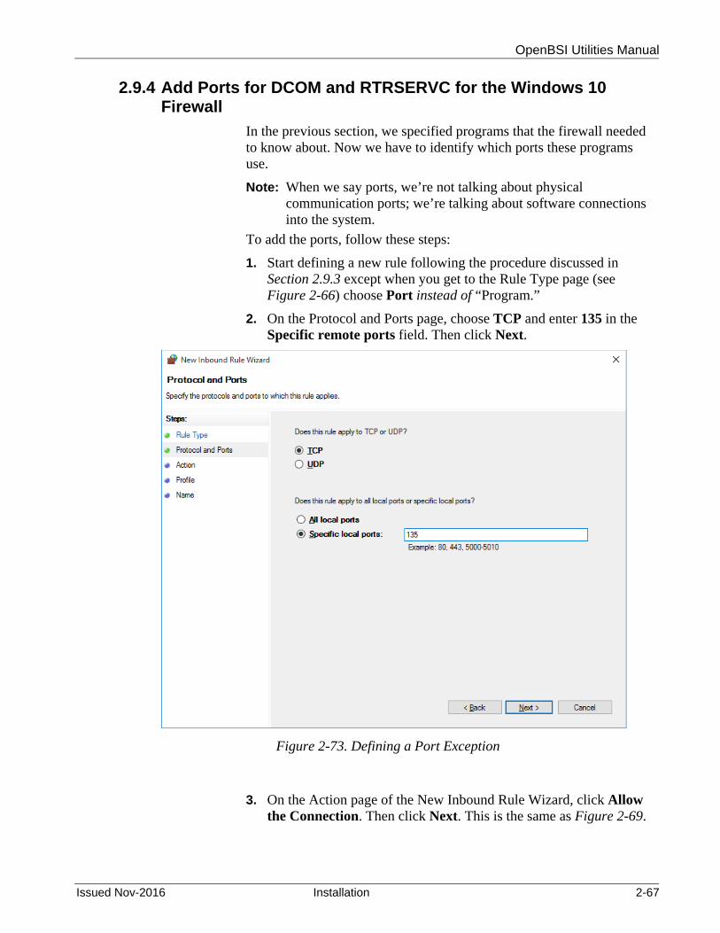
OpenBSI Utilities Manual
Issued Nov-2016 Installation 2-67
2.9.4 Add Ports for DCOM and RTRSERVC for the Windows 10 Firewall
In the previous section, we specified programs that the firewall needed to know about. Now we have to identify which ports these programs use.
Note: When we say ports, we’re not talking about physical communication ports; we’re talking about software connections into the system.
To add the ports, follow these steps:
1. Start defining a new rule following the procedure discussed in Section 2.9.3 except when you get to the Rule Type page (see Figure 2-66) choose Port instead of “Program.”
2. On the Protocol and Ports page, choose TCP and enter 135 in the Specific remote ports field. Then click Next.
Figure 2-73. Defining a Port Exception
3. On the Action page of the New Inbound Rule Wizard, click Allow the Connection. Then click Next. This is the same as Figure 2-69.

OpenBSI Utilities Manual
2-68 Installation Issued Nov-2016
4. On the Profile page of the New Inbound Rule wizard, specify the cases where the DCOM port inbound rule applies. This is the same as Figure 2-70.
5. On the Name page of the New Inbound Rule Wizard, specify a Name for the rule, and optionally enter a description. Then click Finish. This is similar to Figure 2-71.
6. Now repeat the entire procedure but instead of creating an inbound rule, double-click on Outbound Rules first and create outbound rules for the DCOM port following the same basic steps.
7. Now create both inbound and outbound rules for RTRSERVC. Choose Port on the Rule Type page and on the Protocol and Ports page, enter 1236 for the specific remote ports and choose TCP. Then click Next.
Note: The reason we say “1236” is that “1236” is the default port number used by RTRSERVC. That number is initially set in the TCP Port Number for Router Process field of the IP Parameters dialog box in NetView’s System Wizard. If you originally set it to something different than 1236, you should use that number here, instead of 1236.
8. On the Name page enter rtrservc for the port’s Name and click Finish.
2.9.5 Add Ports for the Bristol IP Driver (BSIPDRV) for the Windows 10 Firewall
This procedure is almost identical to previous sections. We are adding two additional ports for the Bristol IP Driver (BSIPDRV). One is for the driver itself, and the other is for Time Synchronization messages. The main difference from the previous step is the port numbers and the port type, which is UDP, instead of TCP.
To add the ports, follow these steps:
1. Start defining a new rule following the procedure discussed in Section 2.9.3 except when you get to the Rule Type page (see Figure 2-66) choose Port instead of “Program.”
2. On the Protocol and Ports page, choose UDP and enter 1234 in the Specific remote ports field. Then click Next.

OpenBSI Utilities Manual
Issued Nov-2016 Installation 2-69
Figure 2-74. Defining a Port Exception for BSIPDRV
3. On the Action page of the New Inbound Rule Wizard, click Allow the Connection. Then click Next. This is the same as Figure 2-69.
4. On the Profile page of the New Inbound Rule wizard, specify the cases where the BSIPDRV port inbound rule applies. This is the same as Figure 2-70.
5. On the Name page of the New Inbound Rule Wizard, specify a Name for the rule, and optionally enter a description. Then click Finish. This is similar to Figure 2-71.
6. Now repeat the entire procedure but instead of creating an inbound rule, double-click on Outbound Rules first and create outbound rules for the BSIPDRV port following the same basic steps.
7. Now repeat the entire procedure to add the second port for BSIPDRV except enter 1235 for the Specific remote ports. You must create both inbound and outbound rules.
Note: Again, we’re saying “1234” and “1235” because those are the default port numbers used by BSIPDRV. Those numbers are

OpenBSI Utilities Manual
2-70 Installation Issued Nov-2016
initially set in the UDP Port Number for IP Driver and UDP Port Number for Time Synch fields of the IP Parameters dialog box in NetView’s System Wizard. If you originally set them to something different than 1234 and 1235, you should use those numbers here, instead.
2.9.6 Reconfiguring the DCOM Software for the Windows 10 Firewall
You must reconfigure the DCOM software for the Object Server to function correctly. This process is similar to that for other Windows operating systems. See Section 2.7.6.
2.10 Using OpenBSI with Microsoft® Windows 2012 Server
For OpenBSI to function with Windows 2012 Server need to re-configure the Windows Firewall software, and re-configure DCOM software.
2.10.1 Reconfiguring the Windows 2012 Server Firewall
Reconfiguring the firewall involves either disabling it (not recommended in most cases) or making certain OpenBSI applications exceptions to the firewall, to let them through.
Note: If Object Server is currently running, you must shut it down during this configuration.
2.10.2 Disabling the Windows 2012 Server Firewall
If the Windows firewall is the only firewall protection you have, we recommend you leave it enabled, and skip to Section 2.10.3. If, however, you have a corporate firewall already installed and it is operating correctly, you may decide that the Windows firewall is unnecessary. If this is the case, you can disable the Windows firewall.
Caution Only perform these next four steps if you have a separate corporate firewall which renders the Windows firewall unnecessary.
1. From the Windows™ Control Panel, double-click on System and
Security and then select Windows Firewall.
2. Click on the Turn Windows Firewall on or off link.
3. On the General page of the Windows Firewall dialog box, select the Off button, then click on OK.
4. Skip the remaining steps in this sub-section, and continue with the section “Reconfiguring the DCOM Software.”

OpenBSI Utilities Manual
Issued Nov-2016 Installation 2-71
2.10.3 Making Object Server an Exception to the Windows 2012 Server Firewall
If you install Object Server, you need to grant it as an exception to the Windows Firewall.
1. From the Windows™ Control Panel, double-click on System and Security then choose Windows Firewall.
2. Click Allow an app or feature through Windows Firewall.
Figure 2-75. Allow a Program Through the Firewall
3. On the Allowed Apps page, click Change Settings.
Click “Allow an app or feature through Windows Firewall”

OpenBSI Utilities Manual
2-72 Installation Issued Nov-2016
Figure 2-76. Defining an Inbound Rule
4. In the Add an app page, select the Object Server app and click Add.
Figure 2-77. Add an app dialog box
Click “Change Settings”

OpenBSI Utilities Manual
Issued Nov-2016 Installation 2-73
5. In the Windows Firewall with Advanced Security page, double-click on Inbound Rules.
Figure 2-78. Defining an Inbound Rule
6. On the Inbound Rules page click New Rule.
Figure 2-79. Defining a New Inbound Rule
7. In the Rule Type page of the New Inbound Rule Wizard, click Program. Then click Next.
Double-click on “Inbound Rules”
Click “New Rule”

OpenBSI Utilities Manual
2-74 Installation Issued Nov-2016
Figure 2-80. New Inbound Rule Wizard – Rule Type page
8. On the Program page (see Figure 2-81.), you can add Object Server to the list of authorized communicators through the Windows Firewall. Click the Browse button next to the This Program Path field to locate the Bristol OPC Server (BristolOPCServer.exe).
Click “Program” then click “Next”
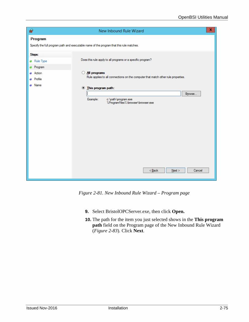
OpenBSI Utilities Manual
Issued Nov-2016 Installation 2-75
Figure 2-81. New Inbound Rule Wizard – Program page
9. Select BristolOPCServer.exe, then click Open.
10. The path for the item you just selected shows in the This program path field on the Program page of the New Inbound Rule Wizard (Figure 2-83). Click Next.

OpenBSI Utilities Manual
2-76 Installation Issued Nov-2016
Figure 2-82. New Inbound Rule Wizard – Program page
11. On the Action page of the New Inbound Rule Wizard, click Allow the Connection. Then click Next.

OpenBSI Utilities Manual
Issued Nov-2016 Installation 2-77
Figure 2-83. Program Path for the Exception
12. On the Profile page of the New Inbound Rule wizard, specify the cases where the ObjectServer inbound rule applies.

OpenBSI Utilities Manual
2-78 Installation Issued Nov-2016
Figure 2-84. Choosing Where the Exception Applies
13. On the Name page of the New Inbound Rule Wizard, specify a Name for the rule, and optionally enter a description. Then click Finish.

OpenBSI Utilities Manual
Issued Nov-2016 Installation 2-79
Figure 2-85. Name the Rule
14. If you use the Object Server Alarm and Event Server (BristolAEServer.exe), repeat this entire procedure for that executable.
15. Now repeat the entire procedure again but instead of creating inbound rules, double-click on Outbound Rules first and create outbound rules for these programs following the same basic steps.
Figure 2-86. Defining an Outbound Rule
Double-click on “Outbound Rules”

OpenBSI Utilities Manual
2-80 Installation Issued Nov-2016
2.10.4 Add Ports for DCOM and RTRSERVC for the Windows 2012 Server Firewall
In the previous section, we specified programs that the firewall needed to know about. Now we have to identify which ports these programs use.
Note: When we say ports, we’re not talking about physical communication ports; we’re talking about software connections into the system.
To add the ports, follow these steps:
1. Start defining a new rule following the procedure discussed in Section 2.10.3 except when you get to the Rule Type page (see Figure 2-66) choose Port instead of “Program.”
2. On the Protocol and Ports page, choose TCP and enter 135 in the Specific remote ports field. Then click Next.
Figure 2-87. Defining a Port Exception
3. On the Action page of the New Inbound Rule Wizard, click Allow the Connection. Then click Next. This is the same as Figure 2-69.

OpenBSI Utilities Manual
Issued Nov-2016 Installation 2-81
4. On the Profile page of the New Inbound Rule wizard, specify the cases where the DCOM port inbound rule applies. This is the same as Figure 2-70.
5. On the Name page of the New Inbound Rule Wizard, specify a Name for the rule, and optionally enter a description. Then click Finish. This is similar to Figure 2-71.
6. Now repeat the entire procedure but instead of creating an inbound rule, double-click on Outbound Rules first and create outbound rules for the DCOM port following the same basic steps.
7. Now create both inbound and outbound rules for RTRSERVC. Choose Port on the Rule Type page and on the Protocol and Ports page, enter 1236 for the specific remote ports and choose TCP. Then click Next.
Note: The reason we say “1236” is that “1236” is the default port number used by RTRSERVC. That number is initially set in the TCP Port Number for Router Process field of the IP Parameters dialog box in NetView’s System Wizard. If you originally set it to something different than 1236, you should use that number here, instead of 1236.
8. On the Name page enter rtrservc for the port’s Name and click Finish.
2.10.5 Add Ports for the Bristol IP Driver (BSIPDRV) for the Windows 2012 Server Firewall
This procedure is almost identical to previous sections. We are adding two additional ports for the Bristol IP Driver (BSIPDRV). One is for the driver itself, and the other is for Time Synchronization messages. The main difference from the previous step is the port numbers and the port type, which is UDP, instead of TCP.
To add the ports, follow these steps:
9. Start defining a new rule following the procedure discussed in Section 2.9.3 except when you get to the Rule Type page (see Figure 2-80) choose Port instead of “Program.”
10. On the Protocol and Ports page, choose UDP and enter 1234 in the Specific remote ports field. Then click Next.

OpenBSI Utilities Manual
2-82 Installation Issued Nov-2016
Figure 2-88. Defining a Port Exception for BSIPDRV
11. On the Action page of the New Inbound Rule Wizard, click Allow the Connection. Then click Next. This is the same as Figure 2-83.
12. On the Profile page of the New Inbound Rule wizard, specify the cases where the BSIPDRV port inbound rule applies. This is the same as Figure 2-84.
13. On the Name page of the New Inbound Rule Wizard, specify a Name for the rule, and optionally enter a description. Then click Finish. This is similar to Figure 2-85.
14. Now repeat the entire procedure but instead of creating an inbound rule, double-click on Outbound Rules first and create outbound rules for the BSIPDRV port following the same basic steps.
15. Now repeat the entire procedure to add the second port for BSIPDRV except enter 1235 for the Specific remote ports. You must create both inbound and outbound rules.
Note: Again, we’re saying “1234” and “1235” because those are the default port numbers used by BSIPDRV. Those numbers are

OpenBSI Utilities Manual
Issued Nov-2016 Installation 2-83
initially set in the UDP Port Number for IP Driver and UDP Port Number for Time Synch fields of the IP Parameters dialog box in NetView’s System Wizard. If you originally set them to something different than 1234 and 1235, you should use those numbers here, instead.
2.10.6 Reconfiguring the DCOM Software for the Windows 2012 Server Firewall
You must reconfigure the DCOM software for the Object Server to function correctly. This process is similar to that for other Windows operating systems. See Section 2.7.6.
2.11 Recommendations for Using OpenBSI ActiveX Controls
You may encounter problems using some OpenBSI ActiveX controls (for example, in web pages) in some Windows platforms. Some portions of controls may not be displayed, for example. (See security message displayed below):
Note: Depending upon the version of Windows you are using, the screens shown in this section may vary somewhat.
Figure 2-89. Internet Explorer warning
To prevent these restrictions from affecting the operation of ActiveX controls, do the following:
1. Open the Windows Control Panel.
2. Select Internet Options.
3. Click the Advanced tab.
4. Under the Settings for Security, make sure “Allow active content to run in files on My Computer” is checked.

OpenBSI Utilities Manual
2-84 Installation Issued Nov-2016
Figure 2-90. Internet Options – Advanced tab
5. You may need to reboot your PC to ensure the new settings take effect.
Note: In addition, Microsoft® has changed Windows XP so that ActiveX controls are disabled, by default, in Internet Explorer. Because this affects the OpenBSI controls, you may, instead, want to make use of the simple browser option, by removing the BBIWebBrowser option in the DATASERV.INI file, or by setting it to 1. See Appendix E.
Make sure this is checked.

OpenBSI Utilities Manual
Issued Nov-2016 Quickstart – BSAP Networks 3-1
Chapter 3 – Quickstart (OpenBSI BSAP Communications)
This section describes the minimum steps necessary to start communications between an OpenBSI workstation and a network of ControlWave / Network 3000 (RTUs). It assumes that:
You installed your RTUs and configured them for BSAP communications.
You connected and tested the cables to the RTU network. You installed OpenBSI Network Edition on your PC.
In This Chapter
3.1 Start NetView and Open a New Set of NETDEF Files .................... 3-2 3.2 Use the System Wizard to Define Your Network Host PC (NHP) ... 3-4
3.2.1 System Wizard – Page 1 ...................................................... 3-4 3.2.2 System Wizard: Page 2 ........................................................ 3-5 3.2.3 System Wizard: Page 3 ........................................................ 3-6
3.3 Define Your BSAP Network Using the Network Wizard .................. 3-8 3.3.1 Network Wizard: Page 1 ....................................................... 3-9 3.3.2 Network Wizard: Page 2 ..................................................... 3-10
3.4 Add Controllers to the BSAP Network Using the RTU Wizard ...... 3-11 3.4.1 RTU Wizard Page 1 ........................................................... 3-12 3.4.2 RTU Wizard Page 2 ........................................................... 3-13 3.4.3 RTU Wizard Page 3 ........................................................... 3-15
3.5 Define Your Communication Line using the Comm Line Wizard .. 3-16 3.5.1 Comm Line Wizard Page 1 ................................................ 3-17 3.5.2 Comm Line Wizard Page 2 ................................................ 3-18
3.6 Verify Communications Are Active Using DataView ...................... 3-19 3.6.1 If NetView communicates…. .............................................. 3-21 3.6.2 If NetView fails to communicate… ..................................... 3-22
We divided this chapter into six sections; each section contains multiple steps:
Section 3.1 describes how to start NetView and open a new set of Network Definition Files (also known as NETDEF files). NetView controls OpenBSI communications, and operates according to user-specified parameters in the NETDEF files. You must complete this section first.
Section 3.2 describes how to use the System Wizard to define a Network Host PC. For BSAP networks, the Network Host PC is the Network Master (Level 0) node.
Section 3.3 describes how to use the Network Wizard to define the type of network, and the maximum number of slave nodes of master nodes on various levels of the network.
Section 3.4 describes how to use the RTU Wizard to define the individual RTUs which make up the network defined in Section 3.3.
Section 3.5 describes how to use the Comm Line Wizard to define the communication line characteristics for the network created in Section

OpenBSI Utilities Manual
3-2 Quickstart – BSAP Networks Issued Nov-2016
3.3. These characteristics include the name of the communication line (COM1 or COM2), the baud rate, and the valid slave address range.
Section 3.6 describes how to use DataView to verify communications.
3.1 Start NetView and Open a New Set of NETDEF Files
Note: If you have not registered your copy of OpenBSI Network Edition, the system prompts you to do so. Unregistered software only runs for a maximum of 60 days; after that time, you must complete the registration to continue to use it. For more information on the registration process, see Chapter 2.
1. Click Start > Programs > OpenBSI Tools > NetView and NetView starts. (See Figure 3-1.)
Figure 3-1. NetView Main Window
2. To open a new NETDEF file, click on the New File icon, or click File>New. This calls up the “Save As” dialog box.
New File icon

OpenBSI Utilities Manual
Issued Nov-2016 Quickstart – BSAP Networks 3-3
Figure 3-2. Save As dialog box
3. In the “Save As” dialog box, enter a name for your NETDEF file, and click Save. In addition to the NDF file, this also automatically saves a set of database files (*.MDB, *.DSN, and *.LDB) which share the same file basename as the NDF file. We call these the Network Definition (NETDEF) files. After the save operation completes, the System Wizard starts. Proceed to Section 3.2.
First enter a name, then click “Save.”

OpenBSI Utilities Manual
3-4 Quickstart – BSAP Networks Issued Nov-2016
3.2 Use the System Wizard to Define Your Network Host PC (NHP)
After you save your NETDEF files (see the previous section), the System Wizard activates, so you can define a Network Host PC (NHP). The NHP serves as your BSAP Network Master.
3.2.1 System Wizard – Page 1
Figure 3-3. System Wizard – Step 1 of 3
On the first page of the System Wizard (Figure 3-3) define the following items, or use the defaults provided.
Most users can leave the “Advanced Parameters” at their default values.
This number defines the maximum number of RTUs your system can support. This must be at least “100.”
Ignore the “IP Parameters.” They don’t apply when defining a purely BSAP network.
A controller (node) must respond to a program (such as DataView) within this time period. If no response is received, that node is said to have “timed out.” In specifying this value, the baud rate, number of network levels, and the poll periods must all be taken into consideration. This value MUST NOT be less than the sum of the poll periods for each level of the network, but should not be too large, since that would delay the initiation of a retry, if an attempt to send a message fails.
Click here to go to page 2.

OpenBSI Utilities Manual
Issued Nov-2016 Quickstart – BSAP Networks 3-5
The maximum number of RTUs in your system. The default is 1000. The minimum value for this is 100, if you have less than 100 RTUs, set the value to 100. Note: This number must include all RTU's on all levels; not just level 1 RTUs.
The maximum amount of time it takes for any RTU to respond to a message from a program. (A program could be DataView, NetView, OpenEnterprise, etc.)
The total number of attempts OpenBSI makes to communicate with top-level (level 1) RTUs.
The file paths where the system stores ACCOL load files, and the OpenBSI journal file.
To advance to the next page of the System Wizard, click Next. To return to a previous page, click Back.
Caution Once you exit the System Wizard, you cannot change many of the defined items on-line within NetView. You can change certain items, however, through the off-line Database Config Utility. You can also edit system constants in the NDF file, directly, using any ASCII text editor. See Appendix B for more information.
3.2.2 System Wizard: Page 2
You define additional system parameters from the second page of the System Wizard:
From the Security button, you can specify the minimum security levels an operator needs to change the inhibit/enable status of a signal, or to alter DataView lists (*.DVL) or DataView recipes (*.RCP). Also, you can specify whether you want to use the username/password method of security (which requires additional configuration in your ACCOL load) instead of passwords-only (which is the default).
From the Refresh Rates button, you can specify the rate at which signal, data array, and communication statistics update on the screen.
From the Collection push button, you can specify certain communication parameters for the legacy OpenBSI Data Collector program.
When you finish with the entries on Page 2 of the System Wizard, click Next to go to Page 3.

OpenBSI Utilities Manual
3-6 Quickstart – BSAP Networks Issued Nov-2016
Figure 3-4. System Wizard – Step 2 of 3
3.2.3 System Wizard: Page 3
You can use the third page of the System Wizard to define parameters specific to this Network Host PC, including a name for the NHP, and the IP address(es) for the NHP. If available, NetView obtains default information from your configured PC TCP/IP information. NOTE: Since this is a purely BSAP network, leave these entries at their default values and click Finish to exit the System Wizard.
Click here to go to page 3.
Usually you can leave these at their defaults unless your system has some special requirements.

OpenBSI Utilities Manual
Issued Nov-2016 Quickstart – BSAP Networks 3-7
Figure 3-5. System Wizard – Step 3 of 3
After NetView processes your System Wizard data, it presents the following message box (See Figure 3-6.)
Figure 3-6. Default User “SYSTEM” message box
This message box tells you that this new set of NETDEF files has a single user who can access it for editing purposes. That user has the name “SYSTEM”, and does not require a password. When you click OK OpenBSI automatically logs you on as the SYSTEM user.
When signing on, you can leave the “SYSTEM” user with the “Password” field blank to disable OpenBSI security; allowing you to avoid the requirement to log on repeatedly during initial configuration activities.
Click “Finish” to exit the System Wizard.
These parameters are not important in a pure BSAP network, and you may leave them at their defaults. If, however, you ever connect this PC to an IP network, you MUST change these parameters to reflect the conventions of the network.

OpenBSI Utilities Manual
3-8 Quickstart – BSAP Networks Issued Nov-2016
Caution We strongly recommend that when you complete installation and configuration activities that you assign a password for the SYSTEM user. (See Chapter 6 for details.)
Figure 3-7. Sign On dialog box
3.3 Define Your BSAP Network Using the Network Wizard
After you complete Section 3.2, an icon of a PC (that represents your NHP) appears on the left-hand side of the NetView window. You now can define a BSAP network underneath it with the Network Wizard.
There are two ways to activate the Network Wizard:
One way is to right click on the NHP, and select Add>Network from the pop-up menu.
Figure 3-8. Starting the Network Wizard – Method 1
The other way to activate the Network Wizard is to first click View>Toolbox from the menu bar. This activates the Toolbox. From the Toolbox (see Figure 3-9). Now drag the BSAP network symbol over to the NHP icon. This activates the Network Wizard.
Right-click on the NHP, then choose Add>Network

OpenBSI Utilities Manual
Issued Nov-2016 Quickstart – BSAP Networks 3-9
Figure 3-9. Starting the Network Wizard – Method 2
Either of these methods starts the Network Wizard.
3.3.1 Network Wizard: Page 1
On the first page of the Network Wizard, you need to:
Provide a name for the network. It doesn't really matter what you name it, so long as the name is unique in the system.
Choose BSAP Network for the Network Type. Note: If you activate the Network Wizard using the Toolbox, and choose the BSAP network symbol, you automatically choose BSAP.
If you want to, you can also alter the default time out period.
When you finish with the first page of the Network Wizard, click Next.
Drag this symbol over to the NHP icon.

OpenBSI Utilities Manual
3-10 Quickstart – BSAP Networks Issued Nov-2016
Figure 3-10. Network Wizard – Step 1 of 2
3.3.2 Network Wizard: Page 2
On the second page of the Network Wizard, you need to:
Specify the maximum number of RTUs under a given master node, on each level of your BSAP network. BSAP networks support from one to six network levels.
Click Finish to exit the Network Wizard.
Figure 3-11. Network Wizard – Step 2 of 2
Enter a name for the BSAP network. It must be unique in this OpenBSI system.
Click here to go to page 2.
Choose “BSAP Network.”
Exercise care when specifying these numbers because you CANNOT change them on-line once you exit the Network Wizard. (You can change them using the Off-Line Database Configuration Utility.)
Click here to exit the Network Wizard.

OpenBSI Utilities Manual
Issued Nov-2016 Quickstart – BSAP Networks 3-11
3.4 Add Controllers to the BSAP Network Using the RTU Wizard
Now you can add the actual RTUs to the network using the RTU Wizard. There are two ways to activate the RTU Wizard:
One way is to right click once on the location in the network where you want to add the RTU (when you start a new network, this is just the network name) then select Add>RTU from the pop-up menu.
Figure 3-12. Starting the RTU Wizard – Method 1
The other way to start the RTU Wizard is to drag the icon for the RTU you want to add from the Toolbox, over to the place in the network where you want to add it.
Figure 3-13. Starting the Network Wizard – Method 2
Right-click on the network and choose Add>RTU.
3530-xx TeleFlow series
RTU 3310
RTU 3305
DPC 3335
ControlWave
ControlWave I/O Expansion Rack
ControlWave EFM
ControlWave XFC
ControlWave Express
CW_30 MVT (3808/4088B)
CW_10
ControlWave GFC
ControlWave MICRO
ControlWave LP
Virtual Node
3508 TeleTrans
DPC 3330
GFC 3308-xx

OpenBSI Utilities Manual
3-12 Quickstart – BSAP Networks Issued Nov-2016
Notes:
Certain types of RTUs cannot support slave nodes, therefore, you must place them at the bottom (terminal) level of the network.
If you use expanded node addressing (also known as expanded BSAP or EBSAP), NetView requires that you define virtual nodes on level 1 of the network. This thereby requires you to define the expanded addressing slave nodes on level 2. You define virtual nodes like any other RTU in NetView. See the Expanded Node Addressing section of the ACCOL II Reference Manual (document# D4044) or the ControlWave Designer Programmer’s Handbook (document# D5125) for more information on expanded node addressing.
3.4.1 RTU Wizard Page 1
On the first page of the RTU Wizard, you need to:
Specify how many RTUs you want to add at a given network level, under a single master (NHP is the master for level 1 RTUs). If desired, you can enter “1” to add just one RTU at a time, but then you must invoke the RTU Wizard separately for each RTU you want to add.
If you enter multiple RTUs, choose a numbering scheme, and a starting number. The RTU Wizard uses these values (along with a text string you enter on page 2 of the RTU Wizard) to assign node names for each of the new RTUs. (You can easily change the names later by right-clicking on an RTU, and selecting "Properties" from the pop-up menu.)

OpenBSI Utilities Manual
Issued Nov-2016 Quickstart – BSAP Networks 3-13
Figure 3-14. RTU Wizard – Step 1 of 3
Click Next to go to the second page of the RTU Wizard.
3.4.2 RTU Wizard Page 2
On the second page of the RTU Wizard, you need to:
Specify the name of the RTU. If you define only a single RTU, enter the complete name. If you want to define multiple RTUs on the same level, specify only the beginning portion of the name; the RTU Wizard appends numbers to the RTU name (based on the numbering scheme specified on page 1 of the RTU Wizard). The complete name must not exceed 16 characters. In general, we recommend you create names that only use alpha-numeric characters (letters, numbers) plus the underscore. The RTU Wizard does not support spaces in RTU names, but you can use punctuation marks.
Note: If you use any old DOS-based ACCOL tools, they only support RTU names of four characters or less.
You can add controllers (RTUs) one at a time, invoking the RTU Wizard for each one you add, or you can add multiple RTUs all at the same time, if they are on the same network level.
Click here to go to page 2.

OpenBSI Utilities Manual
3-14 Quickstart – BSAP Networks Issued Nov-2016
Specify the type of controller (RTU). Specify the control strategy file name for the RTU (this defaults to
the RTU name). If your ControlWave file includes multiple resources, specify which
resource you want to use with this RTU. Specify a description of the RTU. (Optional) NOTE: If you define
multiple RTUs, each RTU shares the same description; it may be easier to edit this information, on a per-RTU basis, later.
Specify a startup web page you want to associate with this RTU. Any RTU supports a startup web page, stored on the PC, which receives data through OpenBSI.
Figure 3-15. RTU Wizard – Step 2 of 3
Click Next to go to page 3 of the RTU Wizard.
If you are adding a single RTU, enter the compete name here. If you are adding multiple RTUs, enter only the portion of the name which is combined with the numbers specified on page 1. The complete RTU name cannot exceed 16 characters.
If you are adding a single RTU, enter the compete name here. If you are adding multiple RTUs, enter only the portion of the name which is combined with the numbers specified on page 1. The complete RTU name cannot exceed 16 characters.
Choose the type of controller (RTU).
If you are adding multiple RTUs, leave this blank for now.
This defines the optional startup HTML page used with this RTU. Specify the full path and filename of the HTML file stored on your workstation.
Most users can ignore the Advanced Parameters.
Click here to go to page 3.
By default the RTU name is used for the control strategy filename. For ControlWave, specify a full path in addition to the filename. For Network 3000, the system assumes that the file resides in the ACCOL directory.

OpenBSI Utilities Manual
Issued Nov-2016 Quickstart – BSAP Networks 3-15
3.4.3 RTU Wizard Page 3
On the third page of the RTU Wizard, you need to:
Specify the BSAP local address of the RTU (which must range from 1 to 127). If you define multiple RTUs, specify the address of the first RTU; the RTU Wizard assigns the address of each additional RTU sequentially in ascending order.
The third page of the RTU Wizard also displays the network level, and the predecessor node (the master of this slave node).
Figure 3-16. RTU Wizard – Step 3 of 3
Click Finish to exit the RTU Wizard.
The BSAP local address you enter here must match the address configured at the RTU (either through the Flash Configuration utility or switch/jumper settings.
Click here to exit the RTU Wizard.

OpenBSI Utilities Manual
3-16 Quickstart – BSAP Networks Issued Nov-2016
Once you define your RTUs, if necessary, you can edit their properties if you right click on the RTU icon, and select "Properties" from the pull down menu.
Figure 3-17. Modifying RTU Properties
3.5 Define Your Communication Line using the Comm Line Wizard
Now that your RTU network exists, the last important thing you have to do is define the characteristics of the communication line which the RTUs use.
There are two ways to activate the Comm Line Wizard:
One way is to right click on the NHP icon, and select Add>Line from the pop-up menu to start the Comm Line Wizard.
Figure 3-18. Starting the Comm Line Wizard – Method 1
The other way to start the Comm Line Wizard is to drag the BSAP comm line icon from the Toolbox, over to the NHP icon.

OpenBSI Utilities Manual
Issued Nov-2016 Quickstart – BSAP Networks 3-17
Figure 3-19. Starting the Comm Line Wizard – Method 2
3.5.1 Comm Line Wizard Page 1
On the first page of the Comm Line Wizard, you need to:
Specify the name of the Communication Line. For BSAP users, this is typically COM1 or COM2.
Specify the type of Communication Line. For purposes of this example, you must choose BSAP Line.
Figure 3-20. Comm Line Wizard – Step 1
Click Next to go to Page 2 of the Comm Line Wizard.
Drag the BSAP Line icon over to the NHP.
(Use this only for a BSAP Local Line)
(Use this ONLY for an EBSAP Line)
For BSAP networks, you typically choose “COM1”
Choose “BSAP LIne”
Click here to go to page 2

OpenBSI Utilities Manual
3-18 Quickstart – BSAP Networks Issued Nov-2016
3.5.2 Comm Line Wizard Page 2
On the second page of the Comm Line Wizard, you need to:
Specify the range of local addresses for level 1 RTUs. Specify the baud rate for the communication line. Specify which BSAP network uses this COM line. (Not required in
this case, since we only have one BSAP network right now.) Specify the rate at which NetView polls level 1 RTUs for data.
Figure 3-21. Comm Line Wizard – Step 2
Click Finish to exit the Comm Line Wizard.
NetView should now automatically begin to poll the nodes for data. To verify this, follow the steps in Section 3.6.
Page 3 of the Comm Line Wizard contains information on the Port Poll Control, which is unnecessary for this example.
Click Finish to exit the Comm Line Wizard
Most users can ignore the Advanced Parameters
This is the rate at which the NHP requests data from the Level 1 RTUs
If your system includes more than one BSAP network, you must choose which network uses this COM line
These two parameters define the range of local addresses for RTUs on Level 1 of the BSAP network. This must be consistent with entries you made previously in the Network Wizard
The baud rate selected here must match the baud rate setting at the RTU

OpenBSI Utilities Manual
Issued Nov-2016 Quickstart – BSAP Networks 3-19
3.6 Verify Communications Are Active Using DataView
Choose one of your RTUs which has a running control strategy. (If you don’t have an RTU running a control strategy, you need to download a control strategy.)
Warning Never attempt to download an untested program into an RTU currently running an industrial process or plant. Prior to downloading, isolate the RTU from the process and disconnect I/O. Failure to take such precautions could result in injury to persons or damage to property.
To download a control strategy, right click on the icon for that RTU and select RTU>Download (Figure 3-22) to download the appropriate control strategy file into the unit.)
Figure 3-22. Downloading a Control Strategy
When any necessary download completes, right click on the icon for the same RTU, again, and select RTU>DataView to start the DataView utility. Click Security> Sign On from the DataView menu bar. If not already selected, choose the name of the RTU you want to communicate with from the Select New Node dialog box. These node names come directly from the information you entered, previously, in NetView. Enter the appropriate password or the username/ password combination for that RTU and click OK.

OpenBSI Utilities Manual
3-20 Quickstart – BSAP Networks Issued Nov-2016
Figure 3-23. Collecting Data from the RTU Using DataView
If the message “Signed on to remote at level n” appears in the status bar, communications are active. Click the Signal Search icon (shown at left).
The desired node name should appear in the Node field of the Signal Search dialog box.
For ControlWave users: If you know of a specific global variable, enter the text “@GV” (for global variables) in the Instance field and the variable name in the Variable field, or a portion of the variable name with a wildcard, such as “_TIME*” (see Figure 3-24). Otherwise, just leave the Instance and Variable fields blank, and then click OK; DataView displays all variables it can find.
For Network 3000 users: Enter the name #TIME in the Base field, and click OK.

OpenBSI Utilities Manual
Issued Nov-2016 Quickstart – BSAP Networks 3-21
Figure 3-24. Signal Search dialog box
3.6.1 If NetView communicates….
If communications function properly, a screen of variables or signals with “live” data values should appear. If you see that, congratulations! You’ve successfully created your first BSAP network!
Figure 3-25. Signal Search Results Screen

OpenBSI Utilities Manual
3-22 Quickstart – BSAP Networks Issued Nov-2016
Now that you have a working network, you can optionally set these NETDEF files to start automatically every time you start NetView. To do this, change the file base name for all four files (*.NDF, *.MDB, *.DSN, and *.LDB) to “CURRENT”.
3.6.2 If NetView fails to communicate…
If these tests fail, and you see other messages, such as “Node Currently Off-Line,” this indicates an error in one of the previous steps, or some other configuration problem. Try the following:
Re-trace the steps throughout this Quickstart, and check each parameter carefully.
Check for port activity by examining the LEDs associated with the RTU port.
Check for typographical errors in node names. For ACCOL Users: Check your ACCOL source file for errors in the
communication port configuration. If necessary, correct any errors then recompile the load, reset the unit, and then try to re-download the ACCOL load.
Check for hardware problems such as improper switch settings (wrong local address, wrong baud rate) at the RTU, or bad or disconnected cables. If you suspect a problem with a modem or other device, try to connect cables locally to see if you can isolate the problem.
If some communication between NetView and the RTUs occurs, but you are unsure of proper data transmission, call up the Monitor window of NetView, and check the communication statistics for errors.
If problems persist, contact our Technical Support Group for help.

OpenBSI Utilities Manual
Issued Nov-2016 Quickstart – IP Networks 4-1
Chapter 4 – Quickstart (OpenBSI IP Communications)
This section describes the minimum steps necessary to start communications between an OpenBSI workstation and a network of ControlWave/Network 3000 RTUs running Internet Protocol (IP).
It assumes that:
You installed your RTUs and configured them for IP communications.
You connected Ethernet cables to the RTUs. Your PC supports TCP/IP and the PC has a valid IP address and
sub-net mask. See the Windows help files on your system for information about TCP/IP setup.
You installed OpenBSI Network Edition on your PC.
In This Chapter
4.1 Using IP with ControlWave and Network 3000 RTUs ..................... 4-2 4.2 Start NetView and Open a New Set of NETDEF Files .................... 4-3 4.3 Use the System Wizard to Define Your Network Host PC (NHP) ... 4-4
4.3.1 Function of the NHP in an IP Network ................................. 4-4 4.3.2 System Wizard – Page 1 ...................................................... 4-5 4.3.3 System Wizard: Page 2 ........................................................ 4-6 4.3.4 System Wizard: Page 3 ........................................................ 4-7
4.4 Define Your IP Network Using the Network Wizard ........................ 4-9 4.4.1 Network Wizard: Page 1 ..................................................... 4-10 4.4.2 Network Wizard: Page 2 ..................................................... 4-11
4.5 Add Controllers to the IP Network Using the RTU Wizard ............ 4-11 4.5.1 RTU Wizard Page 1 ........................................................... 4-12 4.5.2 RTU Wizard Page 2 ........................................................... 4-14 4.5.3 RTU Wizard Page 3 ........................................................... 4-15 4.5.4 RTU Wizard Page 4 ........................................................... 4-17
4.6 Set RTU Configuration Parameters in Each RTU ......................... 4-18 4.7 Define Your Communication Line using the Comm Line Wizard .. 4-18
4.7.1 Comm Line Wizard Page 1 ................................................ 4-19 4.7.2 Comm Line Wizard Page 2 ................................................ 4-20
4.8 Verify Communications Are Active Using DataView ...................... 4-21 4.8.1 If NetView communicates…. .............................................. 4-23 4.8.2 If NetView fails to communicate… ..................................... 4-24
We divided this chapter into eight sections; most sections contain multiple steps:
Section 4.1 provides certain notes concerning our implementation of IP, and summarizes certain concepts which you need to understand in order to properly configure communications.
Section 4.2 describes how to start NetView, and create a new set of Network Definition Files (also known as NETDEF files). NetView controls OpenBSI communications, and operates according to user-specified parameters in the NETDEF files. You must complete this section before you proceed to the other parts.

OpenBSI Utilities Manual
4-2 Quickstart – IP Networks Issued Nov-2016
Section 4.3 describes how to use the System Wizard to define a Network Host PC (NHP).
Section 4.4 describes how to use the Network Wizard to define the type of network.
Section 4.5 describes how to use the RTU Wizard to define the individual RTUs which make up the network defined in Section 4.4.
Section 4.6. See Chapter 5 for details on running the Flash Configuration Utility.
Section 4.7 describes how to use the Comm Line Wizard to define the communication line characteristics for the network created in Section 4.4. These characteristics include definitions of the valid IP address range for nodes on the line.
Section 4.8 describes how to use DataView to verify communications.
4.1 Using IP with ControlWave and Network 3000 RTUs
This manual discusses Internet Protocol (IP) only for use in communication between OpenBSI and ControlWave/Network 3000 RTUs. The normal intended application is for a “closed circuit” internet (LAN) of RTUs and workstations in a company plant or industrial site.
Warning While, there is no built-in restriction against connecting an IP network of RTUs to the world-wide Internet, remember that any external IP connection (no matter what brand of RTUs and software you choose) poses potential risks. We urge you to change default passwords, as well as default UDP/TCP socket numbers, to lessen the possibility that an unauthorized intruder could gain access to your internal company process control data. These security features help prevent accidental access by plant operators or other internal personnel. Don’t consider them protection against intentional malicious activity by a sophisticated intruder, i.e. professional “hacker”. Consider purchasing commercially-available “firewall” software to gain a further degree of protection against such malicious intrusion.
In order to use IP communication, your RTU must be an IP node.
All ControlWave RTUs are IP nodes. The only Network 3000 IP nodes are 386EX Protected Mode versions of the DPC 3330 and DPC 3335 with PES03 / PEX03 or newer firmware with Ethernet ports or serial IP (PPP) ports.
Your IP network must include a PC workstation which serves as the Network Host PC (NHP). The NHP stores information on the composition of the network. The NHP runs the NetView program which lets you configure, start, monitor, control and stop network communications. NetView stores configuration information about the network in Network Definition (NETDEF) Files.
NetView simplifies configuration activities through a series of “wizards”. These wizards separate the system into four basic

OpenBSI Utilities Manual
Issued Nov-2016 Quickstart – IP Networks 4-3
components, each of which you must configure. The System Wizard lets you define the Network Host PC (NHP). The Network Wizard lets you define the network characteristics. The RTU Wizard lets you define the characteristics of individual RTUs, and the Comm Line Wizard lets you define the characteristics of the communication line.
For Network 3000 users: To use peer-to-peer communication (sending signal or array data between IP RTU's) you must configure IP_Client and IP_Server Modules in ACCOL. (See the ACCOL II Reference Manual (document# D4044) for details.)
For ControlWave users: To use peer-to-peer communication you must configure Client and Server function blocks. (See the on-line help in ControlWave Designer for details.)
IP nodes can communicate with BSAP-only nodes (RTUs which DO NOT support IP communication) if you set up Master and Slave communication ports. You define the BSAP nodes in NetView either as part of a BSAP network; with the NHP serving as the network master, or as a BSAP sub-network directly underneath an IP RTU (with the IP RTU serving as the only level 1 node).
4.2 Start NetView and Open a New Set of NETDEF Files
Note: If you have not registered your copy of OpenBSI Network Edition, the system prompts you to do so. Unregistered software only runs for a maximum of 30 days; after that time, you must complete the registration to continue to use it. For more information on the registration process, see Chapter 2.
1. Click Start > Programs > OpenBSI Tools > NetView and NetView starts. (See Figure 4-1.)
Figure 4-1. NetView Main Window
New File icon

OpenBSI Utilities Manual
4-4 Quickstart – IP Networks Issued Nov-2016
2. To open a new NETDEF file, click on the New File icon, or click File>New. This calls up the “Save As” dialog box.
Figure 4-2. Save As dialog box
3. In the “Save As” dialog box, enter a name for your NETDEF file, and click Save. In addition to the NDF file, this also automatically saves a set of database files (*.MDB, *.DSN, and *.LDB) which share the same file basename as the NDF file. We call these the Network Definition (NETDEF) files. After the save operation completes, the System Wizard starts. Proceed to Section 4.3.
4.3 Use the System Wizard to Define Your Network Host PC (NHP)
After you save your NETDEF files (see the previous section), the System Wizard activates, so you can define a Network Host PC (NHP).
4.3.1 Function of the NHP in an IP Network
If an IP node or an OpenBSI workstation needs to communicate with another IP node or OpenBSI workstation, and it doesn't know the address of the IP Port for that node or workstation, it obtains the necessary addresses and routing information from the NETDEF files at the Network Host PC (NHP).
The concept of the NHP is easier to understand if you consider an analogy to the public telephone system. Most people remember a certain set of phone numbers for people they call frequently, but occasionally, they need to call someone whose number they don't know, so they call directory assistance or use a search engine to obtain the correct phone number. The NHP performs the exact same function as the directory assistance operator or search engine except instead of giving out phone
First enter a name, then click “Save.”

OpenBSI Utilities Manual
Issued Nov-2016 Quickstart – IP Networks 4-5
numbers, it provides address information, on request, for connections to any node in its section of the network.
4.3.2 System Wizard – Page 1
Figure 4-3. System Wizard – Step 1 of 3
On the first page of the System Wizard (Figure 4-3) define the following items, or use the defaults provided.
The maximum number of RTUs in your system. The default is 1000. The minimum value for this is 100, if you have less than 100 RTUs, set the value to 100. Note: This number must include all RTU's on all levels; not just level 1 RTUs.
The maximum amount of time it takes for any RTU to respond to a message from a program. (A program could be DataView, NetView, OpenEnterprise, etc.)
The total number of attempts OpenBSI makes to communicate with top-level (level 1) RTUs.
Most users can leave the “Advanced Parameters” at their default values.
This number defines the maximum number of RTUs your system can support. This must be at least “100.”
These parameters relate to IP security.
A controller (node) must respond to a program (such as DataView) within this time period. If no response is received, that node is said to have “timed out
Click here to go to page 2.
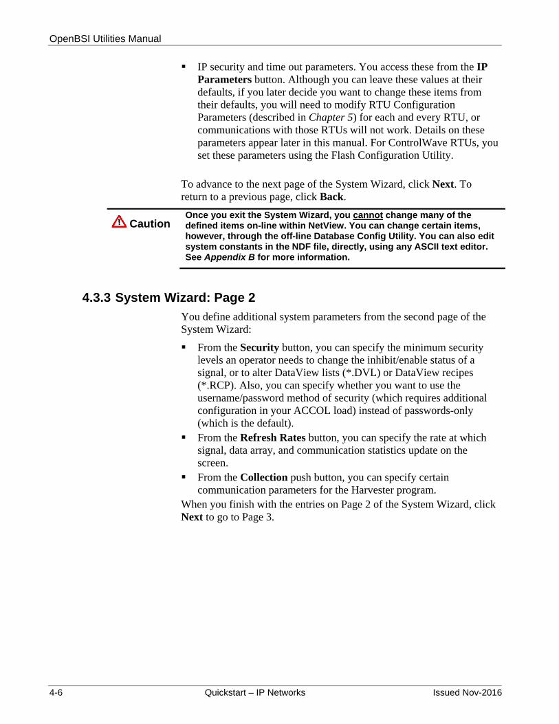
OpenBSI Utilities Manual
4-6 Quickstart – IP Networks Issued Nov-2016
IP security and time out parameters. You access these from the IP Parameters button. Although you can leave these values at their defaults, if you later decide you want to change these items from their defaults, you will need to modify RTU Configuration Parameters (described in Chapter 5) for each and every RTU, or communications with those RTUs will not work. Details on these parameters appear later in this manual. For ControlWave RTUs, you set these parameters using the Flash Configuration Utility.
To advance to the next page of the System Wizard, click Next. To return to a previous page, click Back.
Caution Once you exit the System Wizard, you cannot change many of the defined items on-line within NetView. You can change certain items, however, through the off-line Database Config Utility. You can also edit system constants in the NDF file, directly, using any ASCII text editor. See Appendix B for more information.
4.3.3 System Wizard: Page 2
You define additional system parameters from the second page of the System Wizard:
From the Security button, you can specify the minimum security levels an operator needs to change the inhibit/enable status of a signal, or to alter DataView lists (*.DVL) or DataView recipes (*.RCP). Also, you can specify whether you want to use the username/password method of security (which requires additional configuration in your ACCOL load) instead of passwords-only (which is the default).
From the Refresh Rates button, you can specify the rate at which signal, data array, and communication statistics update on the screen.
From the Collection push button, you can specify certain communication parameters for the Harvester program.
When you finish with the entries on Page 2 of the System Wizard, click Next to go to Page 3.

OpenBSI Utilities Manual
Issued Nov-2016 Quickstart – IP Networks 4-7
Figure 4-4. System Wizard – Step 2 of 3
4.3.4 System Wizard: Page 3
You can use the third page of the System Wizard to define parameters specific to this Network Host PC, including a name for the NHP, and the IP address(es) for the NHP’s IP port(s). If available, NetView obtains default information from your configured PC TCP/IP information.
Click here to go to page 3.
Usually you can leave these at their defaults unless your system has some special requirements.

OpenBSI Utilities Manual
4-8 Quickstart – IP Networks Issued Nov-2016
Figure 4-5. System Wizard – Step 3 of 3
After NetView processes your System Wizard data, it presents the following message box (See Figure 4-6.)
Figure 4-6. Default User “SYSTEM” message box
This message box tells you that this new set of NETDEF files has a single user who can access it for editing purposes. That user has the name “SYSTEM”, and does not require a password. When you click OK OpenBSI automatically logs you on as the SYSTEM user.
Click “Finish” to exit the System Wizard.
Leave the IP Secondary Address at 0.0.0.0 unless this PC has a second TCP/IP port (or there is a redundant backup NHP). In that case, enter the address of the second TCP/IP port or backup NHP here.
Enter a unique name for the NHP.
The IP Primary Address must MATCH the IP address defined for this PC’s primary TCP/IP port.

OpenBSI Utilities Manual
Issued Nov-2016 Quickstart – IP Networks 4-9
When signing on, you can leave the “SYSTEM” user with the “Password” field blank to disable OpenBSI security; allowing you to avoid the requirement to log on repeatedly during initial configuration activities.
Caution We strongly recommend that when you complete installation and configuration activities that you assign a password for the SYSTEM user. (See Chapter 6 for details.)
Figure 4-7. Sign On dialog box
4.4 Define Your IP Network Using the Network Wizard
After you complete Section 4.3, an icon of a PC (that represents your NHP) appears on the left-hand side of the NetView window. You now can define a IP network underneath it with the Network Wizard.
There are two ways to activate the Network Wizard:
One way is to right click on the NHP, and select Add>Network from the pop-up menu.
Figure 4-8. Starting the Network Wizard – Method 1
The other way to activate the Network Wizard is to first click View>Toolbox from the menu bar. This activates the Toolbox. (see Figure 4-9). Now drag the IP network symbol over to the NHP icon. This activates the Network Wizard.
Right-click on the NHP, then choose Add>Network

OpenBSI Utilities Manual
4-10 Quickstart – IP Networks Issued Nov-2016
Figure 4-9. Starting the Network Wizard – Method 2
Either of these methods starts the Network Wizard.
4.4.1 Network Wizard: Page 1
On the first page of the Network Wizard, you need to:
Provide a name for the network. It doesn't really matter what you name it, so long as the name is unique in the system.
Choose “IP” for the Network Type. Note: If you activate the Network Wizard using the Toolbox, and choose the IP network symbol, you automatically choose IP.
If you want to, you can also alter the default time out period.
Figure 4-10. Network Wizard – Step 1 of 2
When you finish with the first page of the Network Wizard, click Next.
Drag this symbol over to the NHP icon.
Enter a name for the IP network. It must be unique in this OpenBSI system.
Click here to go to page 2.
Choose “IP Network.”

OpenBSI Utilities Manual
Issued Nov-2016 Quickstart – IP Networks 4-11
4.4.2 Network Wizard: Page 2
On the second page of the Network Wizard, you need to:
Specify up to four different destinations each, for alarm and RBE data from the RTUs in this network. Each destination must be an OpenBSI workstation. You specify a destination in the form of its IP address. Destination 1 defaults to the address of this NHP.
Click Finish to exit the Network Wizard.
Figure 4-11. Network Wizard – Step 2 of 2
4.5 Add Controllers to the IP Network Using the RTU Wizard
Now you can add the actual RTUs to the network using the RTU Wizard. There are two ways to activate the RTU Wizard:
One way is to right click once on the location in the network where you want to add the RTU (when you start a new network, this is just the network name) then select Add>RTU from the pop-up menu.
Figure 4-12. Starting the RTU Wizard – Method 1
Right-click on the network and choose Add>RTU.
You can specify up to four different destination IP addresses for alarm data and up to four different destination IP addresses for RBE data. These destinations are OpenBSI workstations. By default, “Destination 1” is this NHP.
Click here to exit the Network Wizard.
Use this list box to choose which of the four destinations you want to configure.

OpenBSI Utilities Manual
4-12 Quickstart – IP Networks Issued Nov-2016
The other way to start the RTU Wizard is to drag the icon for the RTU you want to add from the Toolbox, over to the place in the network where you want to add it.
Figure 4-13. Starting the Network Wizard – Method 2
Note: DPC 3330 and DPC 3335 controllers require PES03 / PEX03 (or newer) firmware to support IP communication through OpenBSI.
4.5.1 RTU Wizard Page 1
On the first page of the RTU Wizard, you need to:
Specify how many RTUs you want to add at a given network level, under a single master (NHP is the master for level 1 RTUs). If desired, you can enter “1” to add just one RTU at a time, but then you must invoke the RTU Wizard separately for each RTU you want to add.
If you enter multiple RTUs, choose a numbering scheme, and a starting number. The RTU Wizard uses these values (along with a text string you enter on page 2 of the RTU Wizard) to assign node names for each of the new RTUs. (You can easily change the names later by right-clicking on an RTU, and selecting "Properties" from the pop-up menu.)
DPC 3335
ControlWave
ControlWave I/O Expansion Rack
ControlWave EFM
ControlWave XFC
ControlWave Express
CW_30 CW_10
ControlWave GFC
ControlWave MICRO
ControlWave LP
DPC 3330

OpenBSI Utilities Manual
Issued Nov-2016 Quickstart – IP Networks 4-13
Figure 4-14. RTU Wizard – Step 1 of 4
Click Next to go to the second page of the RTU Wizard.
You can add controllers (RTUs) one at a time, invoking the RTU Wizard for each one you add, or you can add multiple RTUs all at the same time. You can also specify a numbering scheme and starting number if you add multiple RTUs.
Click Next to go to the next page.

OpenBSI Utilities Manual
4-14 Quickstart – IP Networks Issued Nov-2016
4.5.2 RTU Wizard Page 2
On the second page of the RTU Wizard, you need to:
Specify the name of the RTU. If you define only a single RTU, enter the complete name. If you want to define multiple RTUs on the same level, specify only the beginning portion of the name; the RTU Wizard appends numbers to the RTU name (based on the numbering scheme specified on page 1 of the RTU Wizard). The complete name must not exceed 16 characters. In general, we recommend you create names that only use alpha-numeric characters (letters, numbers) plus the underscore. The RTU Wizard does not support spaces in RTU names, but you can use punctuation marks.
Note: If you use any old DOS-based ACCOL tools, they only support RTU names of four characters or less.
Specify the type of controller (RTU). Specify the control strategy file name for the RTU (this defaults to
the RTU name). If your ControlWave file includes multiple resources, specify which
resource you want to use with this RTU. Specify a description of the RTU. (Optional) NOTE: If you define
multiple RTUs, each RTU shares the same description; it may be easier to edit this information, on a per-RTU basis, later.
Specify a startup web page you want to associate with this RTU. Any RTU supports a startup web page, stored on the PC, which receives data through OpenBSI.

OpenBSI Utilities Manual
Issued Nov-2016 Quickstart – IP Networks 4-15
Figure 4-15. RTU Wizard – Step 2 of 4
Click Next to go to page 3 of the RTU Wizard.
4.5.3 RTU Wizard Page 3
On the third page of the RTU Wizard, you need to:
Specify the IP address of the RTU as the Primary IP Address. If you define multiple RTUs, specify the address of the first RTU; the RTU Wizard assigns the IP address of each additional RTU sequentially in ascending order based on the last part of the IP address.
Specify the BSAP Local Address. This is necessary even in an IP network because the local address helps route alarm and RBE messages.
If you are adding a single RTU, enter the compete name here. If you are adding multiple RTUs, enter only the portion of the name which is combined with the numbers specified on page 1. The complete RTU name cannot exceed 16 characters.
If you are adding a single RTU, enter the compete name here. If you are adding multiple RTUs, enter only the portion of the name which is combined with the numbers specified on page 1. The complete RTU name cannot exceed 16 characters.
Choose the type of controller (RTU).
If you are adding multiple RTUs, leave this blank for now.
This defines the optional startup HTML page used with this RTU. Specify the full path and filename of the HTML file stored on your workstation.
Most users can ignore the Advanced Parameters.
Click here to go to page 3.
By default the RTU name is used for the control strategy filename. For ControlWave, specify a full path in addition to the filename. For Network 3000, the system assumes that the file resides in the ACCOL directory.

OpenBSI Utilities Manual
4-16 Quickstart – IP Networks Issued Nov-2016
Figure 4-16. RTU Wizard – Step 3 of 4
Click Next to go to page 4 of the RTU Wizard.
Define the IP address for this RTU’s IP port as the Primary IP Address. This must match the address defined during RTU communications configuration. If you are defining multiple RTUs, enter the address of the first RTU here, addresses of the remaining RTUs are assigned sequentially based on the first address.
If this RTU is part of a redundant pair, enter the “A” unit’s address for the Primary IP Address, and the “B” unit’s address for the Secondary IP Address.
The BSAP local address you enter here must match the address configured at the RTU (either through the Flash Configuration utility or switch/jumper settings). Even though this isn’t a BSAP network, this address is used for routing of alarms and RBE messages.
Click here to go to page 4.

OpenBSI Utilities Manual
Issued Nov-2016 Quickstart – IP Networks 4-17
4.5.4 RTU Wizard Page 4
The fourth page of the RTU Wizard allows you to specify communication fail-over information, and whether to allow proxy direct access.
Figure 4-17. RTU Wizard – Step 4 of 4
For non-redundant RTUs, choose Always try to establish Primary link (default). If the RTU is part of a redundant pair choose Stay with link that is working. (Symmetric). If you choose this option, OpenBSI always attempts to use the current working communication link (either Primary or Secondary) and then if that link fails, fails over to the alternate link.
if you want to allow other OpenBSI workstations direct access to this RTU (without sending messages through this RTU's NHP) choose Yes to the question about access from remote PCs.
if you have a special application-specific reason to disable time synchs to this RTU, you can choose Yes here.
Click Finish to exit the RTU Wizard.
Click here to exit the RTU Wizard

OpenBSI Utilities Manual
4-18 Quickstart – IP Networks Issued Nov-2016
Once you define your RTUs, if necessary, you can edit their properties if you right click on the RTU icon, and select "Properties" from the pull down menu.
Figure 4-18. Modifying RTU Properties
4.6 Set RTU Configuration Parameters in Each RTU
Use Configure Mode in the LocalView utility to configure IP port parameters, and the RTU's IP address (see Chapter 5 for information on how to complete this part of the configuration).
4.7 Define Your Communication Line using the Comm Line Wizard
Now that your RTU network exists, and each RTU has an assigned IP address, the last important thing you have to do is define the characteristics of the communication line which the RTUs use.
There are two ways to activate the Comm Line Wizard:
One way is to right click on the NHP icon, and select Add>Line from the pop-up menu to start the Comm Line Wizard.
Figure 4-19. Starting the Comm Line Wizard – Method 1
The other way to start the Comm Line Wizard is to drag the IP comm line icon from the Toolbox, over to the NHP icon.

OpenBSI Utilities Manual
Issued Nov-2016 Quickstart – IP Networks 4-19
Figure 4-20. Starting the Comm Line Wizard – Method 2
4.7.1 Comm Line Wizard Page 1
On the first page of the Comm Line Wizard, you need to:
Specify the name of the Communication Line. The name must be unique in this OpenBSI system.
Specify the type of Communication Line. For purposes of this example, you must choose IP Line.
Figure 4-21. Comm Line Wizard – Step 1
Click Next to go to Page 2 of the Comm Line Wizard.
Drag the IP line icon over to the NHP
Enter a unique name for the communication line
Choose “IP Line”
Click here to go to page 2

OpenBSI Utilities Manual
4-20 Quickstart – IP Networks Issued Nov-2016
4.7.2 Comm Line Wizard Page 2
On the second page of the Comm Line Wizard, you need to:
Specify the range of IP addresses for this communication line. In the Value fields, specify the portion(s) of the IP address (in dotted decimal format) which are common (i.e. the same) and contiguous starting from the left for all IP addresses on this line. For example, if the RTU's on this line have addresses:
10.210.74.1, 10.211.74.2, and 10.212.74.3,
if you start from the left, "10" is the only common part; enter "10" in the first Value field, and “0” in the other three Value fields. ("74" doesn't count as a common part because it's not contiguous to the 10!) This means the mask for all 8 bits in the 10 must be on, so enter a value of 255 above the 10. Enter zeros in the remaining Mask fields.
Figure 4-22. Comm Line Wizard – Step 2
Click Finish to exit the Comm Line Wizard.
NetView should now automatically begin to communicate with nodes on the IP line. To verify this, follow the steps in Section 4.8.
Click Finish to exit the Comm Line Wizard
Define the range of valid IP addresses for this line. In this example, any IP address beginning with “10” is valid.

OpenBSI Utilities Manual
Issued Nov-2016 Quickstart – IP Networks 4-21
4.8 Verify Communications Are Active Using DataView
Choose one of your RTUs which has a running control strategy. (If you don’t have an RTU running a control strategy, you need to download a control strategy.)
Warning Never attempt to download an untested program into an RTU currently running an industrial process or plant. Prior to downloading, isolate the RTU from the process and disconnect I/O. Failure to take such precautions could result in injury to persons or damage to property.
To download a control strategy, right click on the icon for that RTU and select RTU>Download (Figure 4-23) to download the appropriate control strategy file into the unit.
Figure 4-23. Downloading a Control Strategy
When any necessary download completes, right click on the icon for the same RTU, again, and select RTU>DataView to start the DataView utility. Click Security> Sign On from the DataView menu bar. If not already selected, choose the name of the RTU you want to communicate with from the Select New Node dialog box. These node names come directly from the information you entered, previously, in NetView. Enter the appropriate password or the username/ password combination for that RTU and click OK.

OpenBSI Utilities Manual
4-22 Quickstart – IP Networks Issued Nov-2016
Figure 4-24. Collecting Data from the RTU Using DataView
If the message “Signed on to remote at level n” appears in the status bar, communications are active. Click the Signal Search icon (shown at left).
The desired node name should appear in the Node field of the Signal Search dialog box.
For ControlWave users: If you know of a specific global variable, enter the text “@GV” (for global variables) in the Instance field and the variable name in the Variable field, or a portion of the variable name with a wildcard, such as “_TIME*” (see Figure 4-24). Otherwise, just leave the Instance and Variable fields blank, and then click OK; DataView displays all variables it can find.
For Network 3000 users: Enter the name #TIME in the Base field, and click OK.

OpenBSI Utilities Manual
Issued Nov-2016 Quickstart – IP Networks 4-23
Figure 4-25. Signal Search dialog box
4.8.1 If NetView communicates….
If communications function properly, a screen of variables or signals with “live” data values should appear. If you see that, congratulations! You’ve successfully created an IP network!
(If you want these NETDEF files started automatically every time you start NetView, change the basename for all four files (*.NDF, *.MDB, *.DSN, and *.LDB) to CURRENT.)
Figure 4-26. Signal Search Results Screen

OpenBSI Utilities Manual
4-24 Quickstart – IP Networks Issued Nov-2016
4.8.2 If NetView fails to communicate…
If these tests fail, and you see other messages, such as “Node Currently Off-Line”, this indicates an error in one of the previous steps, or some other configuration problem. Try the following:
Re-trace the steps throughout this Quickstart, and check each parameter carefully.
Verify that all IP addresses and sub-net masks are correct. This is one of the most common errors. If necessary, test TCP/IP connections using the Ping command at the DOS prompt. Also use the Flash Configuration utility to check to see that you defined IP addresses, sub-net masks, and other communication parameters properly at the RTUs. Also check to see that the UDP port/socket numbers specified for security purposes in the NHP match the UDP port/socket numbers defined in each RTU.
Check for port activity by examining the LEDs associated with the RTU communications port.
Check for typographical errors in node names. For Network 3000 users: Check your ACCOL source file for errors
in the IP Slave communication port configuration. If necessary, correct any errors then recompile the load, reset the unit, and then try to re-download the ACCOL load.
If some communication between NetView and the RTU occurs, but you are unsure of proper data transmission, call up the Monitor window of NetView, and check the communication statistics for errors.
If problems persist, contact our Technical Support Group for help.

OpenBSI Utilities Manual
Issued Nov-2016 LocalView 5-1
Chapter 5 – Using LocalView
LocalView lets you:
Establish communications (using BSAP) with a locally connected RTU to allow access by OpenBSI tools (DataView, Downloader, etc.) We call this Local Mode.
Perform field upgrades of system firmware in the locally connected RTU. We call this Flash Mode.
Configure IP addresses and port parameters for certain types of locally connected RTUs. We call this Configure Mode.
Establish IP communications with a single IP node. This allows access by OpenBSI tools (DataView, Downloader, etc.). We call this IP Comm Mode.
In This Chapter
5.1 LocalView Operational Restrictions ................................................. 5-2 5.2 View Mode Files .............................................................................. 5-2 5.3 System Firmware and RTU Configuration Parameters ................... 5-2
5.3.1 System Firmware ................................................................. 5-2 5.3.2 RTU Configuration Parameters ............................................ 5-3 5.3.3 OpenBSI Application Parameters......................................... 5-3
5.4 Methods for Starting LocalView ....................................................... 5-3 5.5 Establishing Communications with an Attached RTU (Local Mode)5-4
5.5.1 Before You Begin ................................................................. 5-4 5.5.2 Starting LocalView and the Setup Wizards .......................... 5-5 5.5.3 Communications Setup Wizard ............................................ 5-6 5.5.4 RTU Setup Wizard ............................................................... 5-8 5.5.5 Dial & Command Setup Wizard............................................ 5-9
5.6 After You Have Finished With the Setup Wizards… ..................... 5-10 5.6.1 Starting Other Programs in Local Mode ............................. 5-11 5.6.2 Reconfiguring the Active View Mode File ........................... 5-13 5.6.3 Saving the View Mode File ................................................. 5-13 5.6.4 Restarting the View Mode File ........................................... 5-14 5.6.5 Viewing Current Configuration Parameters ........................ 5-14
5.7 Upgrading System Firmware in the Field (Flash Mode) ................ 5-14 5.7.1 Before You Upgrade the System Firmware ....................... 5-15 5.7.2 Starting LocalView and the Setup Wizards ........................ 5-16 5.7.3 Communications Setup Wizard .......................................... 5-16 5.7.4 Flash RTU Setup Wizard .................................................... 5-17 5.7.5 Flash Data Setup Wizard ................................................... 5-19 5.7.6 Setting RTU Configuration Parameters in the 3305
(3305 ONLY) ..................................................................... 5-21 5.8 Assigning IP Addresses and Cold Download Parameters for the
Attached RTU (Configure Mode) ................................................... 5-23 5.8.1 Starting LocalView and the Setup Wizards ........................ 5-23 5.8.2 Communications Setup Wizard .......................................... 5-23 5.8.3 IP RTU Setup Wizard ......................................................... 5-24
5.9 Setting RTU Parameters in the Flash Configuration Utility ........... 5-26 5.9.1 Flash Configuration Utility Buttons ..................................... 5-30 5.9.2 Forcing a Reboot of the ControlWave ................................ 5-34 5.9.3 Flash Configuration Utility Tabs ......................................... 5-34 5.9.4 Soft Switches ...................................................................... 5-35 5.9.5 Ports ................................................................................... 5-37

OpenBSI Utilities Manual
5-2 LocalView Issued Nov-2016
5.9.6 IP Parameters .................................................................... 5-49 5.9.7 Application Parameters ...................................................... 5-54 5.9.8 Archive ............................................................................... 5-57 5.9.9 Audit ................................................................................... 5-62 5.9.10 IP Routes ............................................................................ 5-65 5.9.11 Security .............................................................................. 5-67
5.10 Establishing Communications With an IP RTU (IP Comm Mode) . 5-72 5.10.1 Starting LocalView and the Setup Wizards ........................ 5-72 5.10.2 IP Communications Setup Wizard (Step 1 of 3) ................ 5-73 5.10.3 IP Communications Setup Wizard (Step 2 of 3) ................ 5-74 5.10.4 IP Communications Setup Wizard (Step 3 of 3) ................ 5-75
5.1 LocalView Operational Restrictions
With the exception of IP Comm Mode, all LocalView functions apply to a single locally connected RTU. This connection uses either a direct communication cable between the PC and the RTU, or, in Local Mode only, a dial-up modem. Except for IP Comm Mode, all communication uses BSAP. LocalView only supports local BSAP messages; LocalView does not support EBSAP or global BSAP messages.
5.2 View Mode Files
LocalView stores your configuration parameters for a particular mode in a View Mode File. LocalView includes a configuration wizard for each of the different modes. You need to create a separate view mode file for each mode you want to use. LocalView’s configuration wizards store View Mode Files as ASCII text, with a file extension of (*.LVG). Once you create and save a View Mode File, you can open it again for modification purposes, or create a new View Mode File based on it for use with a different RTU. Note: LocalView only allows one active View Mode File at a time.
5.3 System Firmware and RTU Configuration Parameters
Your control strategy file (a ControlWave project which you create in ControlWave Designer or an ACCOL load which you create in ACCOL Workbench) is not the only thing which dictates how your RTU operates. The other things that govern the operation of the RTU are its system firmware, and the RTU configuration parameters.
5.3.1 System Firmware
System firmware is the internal logic that tells the RTU how to understand the control strategy file, how to communicate with OpenBSI, and how to communicate with foreign devices using custom communication protocols, such as Modbus, etc.
Occasionally, you may need to upgrade the system firmware. For example, if you purchase an RTU, and then six months later, Emerson releases a new version of system firmware for that RTU containing new features you want to use (new communication options, etc.) you can

OpenBSI Utilities Manual
Issued Nov-2016 LocalView 5-3
often upgrade the RTU to support the new features through a field installation of new system firmware.
In years past, system firmware resided on a removable EPROM chip that you plugged directly into the RTU – when you needed a firmware upgrade you swapped in the new chip. Today all our current RTUs hold firmware in flash memory. (flash memory is non-volatile storage; if the RTU has a watchdog failure, or you reset it, flash memory preserves the system firmware.) You use LocalView’s flash mode to upgrade the system firmware in the flash memory.
Notes:
Another utility, the Remote System Firmware Downloader, also allows you to upgrade system firmware. For information on that, see Appendix J.
LocalView stores other things in flash memory as well, including the control strategy file (ControlWave project or ACCOL load), and configuration parameters. Don’t confuse these items with the system firmware.
5.3.2 RTU Configuration Parameters
When the RTU starts up, internal settings called RTU configuration parameters govern its operation. These settings include things like:
baud rates the system uses for cold downloads (i.e. an RTU has no control strategy file inside, so it needs a download),
the local address for the RTU in a BSAP network, the Expanded BSAP group number (if the unit resides in an EBSAP
network), the IP address and mask (for IP nodes), various other parameters. In our older model RTUs, customers set these parameters using physical hardware switches. Now we use software settings called soft switches to set these parameters. LocalView’s Configure Mode runs the Flash Configuration Utility to let you to set soft switches and RTU configuration parameters. Both NetView and TechView also allow you to run the Flash Configuration Utility.
5.3.3 OpenBSI Application Parameters
If you need to, you can alter the default OpenBSI application parameters from within LocalView; click View > Application Parms from the menu bar to call up the Application Parameters dialog box. For details on the Application Parameters dialog box, see Chapter 6.
5.4 Methods for Starting LocalView
Note:: You must stop NetView or TechView to run LocalView.

OpenBSI Utilities Manual
5-4 LocalView Issued Nov-2016
If you want to create an all new view mode file, click Start > Programs > OpenBSI Tools > LocalView and LocalView starts.
If you want to start LocalView, and activate a particular view mode file immediately upon startup, you double-click the view mode (*.LVG) filename in Windows™ Explorer, or invoke LocalView from the DOS-prompt, as follows:
C:>loclview filename
where filename is the basename of the view mode file. You can omit the (.LVG) extension. If you include spaces in the filename, you must place quotation marks “ “ around filename.
You can also drag an existing LVG file and drop it on the icon which represents LocalView (shown at left) or on a running instance of the application.
5.5 Establishing Communications with an Attached RTU (Local Mode)
5.5.1 Before You Begin
Before you can establish communications with a locally attached RTU, you need to:
Connect the PC communication cable to one of the available serial ports on the RTU.
For Network 3000 users, if an ACCOL load is already running in the unit, you must choose a port already configured as a Slave, Pseudo Slave, or Pseudo Slave with Alarms Port. If the unit is empty (no ACCOL load running) the first thing you need to do is to download an ACCOL load.
For Network 3000 users, you must know the baud rate of the port you are connecting to, as configured in the running ACCOL load. If there is no running ACCOL load (unit is empty) you should use one of the default ports (as determined by switch settings, or if this is an IP RTU, by soft switches) at 9600 baud. For information on configuring soft switches in an IP RTU, see Assigning IP Addresses and Cold Download Parameters for the Attached RTU (Configure Mode). For IP nodes, you also set the cold download port parameters in Configure Mode.
For ControlWave users, soft switch settings determine the baud rate. (If the Use/Ignore Soft Switches switch is in the OFF position, the ControlWave ignores the soft switches, and the baud rate for all serial ports is 9600 baud except for COM1 which defaults to 115200 baud. Initially, COM1 leaves the factory configured for BSAP, however, the default for COM1 as specified using the default switch is PPP.

OpenBSI Utilities Manual
Issued Nov-2016 LocalView 5-5
5.5.2 Starting LocalView and the Setup Wizards
The following steps assume you do not have a view mode file already configured, and so you want to create a new one:
1. Click Start > Programs > OpenBSI Tools > LocalView and LocalView starts.
Figure 5-1. LocalView
2. In order to use LocalView, you need to define a View Mode File (*.LVG). Enter the basename of the View Mode File in the Name field.
3. If you want to save your View Mode File in a directory other than that shown in the Location field, type in the directory name, or choose an alternate location using the Browse button.
4. When you’ve completed the fields, click Create to activate the setup wizards.
Mode currently in use, either: “Local,” “Flash,” “Configure, or” “IP Comm.”
Error and Status messages. Errors appear with a red background, status messages appear with a yellow background.
“Mod” in red indicates there are unsaved modifications to the current (LVG) view mode file.

OpenBSI Utilities Manual
5-6 LocalView Issued Nov-2016
Notes:
LocalView has multiple setup wizards. You will always need to use the Communication Setup Wizard.
The RTU Setup Wizard is necessary in most cases. The Dial and Command Setup Wizard is only necessary if you
use dial-up communications.
5.5.3 Communications Setup Wizard
Complete the fields in Communication Setup Wizard, as described, below:
Figure 5-2. LocalView Communication Setup Wizard
Field Description
What port would you like to use?
Select the PC port LocalView communicates through (e.g. COM1, COM2, etc.)
What baud rate would you like to use?
Select the baud rate for the PC port. It must match the RTU port baud rate.
Advanced Parameters
Click here only if you want to set parameters for more complex communications configurations, using the Advanced Communication Parameters dialog box.
Select the PC port you want to use for this local connection
Specify the baud rate used for this port.

OpenBSI Utilities Manual
Issued Nov-2016 LocalView 5-7
If you want to accept the defaults for RTU setup you can click Finish. If you want to use RTU setup parameters other than the defaults, click Next to activate the RTU Setup Wizard.
Advanced Communication Parameters Dialog Box
You only need to use these advanced parameters for more complex communications configurations. Most users can skip this.
Figure 5-3. Advanced Communication Parameters dialog box
Field Description
What is the Link Level Timeout Period
Specify the maximum amount of time (in seconds) that OpenBSI waits to receive a response to any one data link transaction. If you enter 0 the system calculates a default timeout based on the baud rate of the line.
Would you like to use RTS/CTS signals?
Click Yes if your communication line uses Ready to Send (RTS) / Clear to Send (CTS) signals (don’t confuse this with ACCOL signals). Otherwise click No.
Front Pad, Back Pad
Use these fields to specify the number of null characters to insert at the beginning (front) or ending (back) of a message. Null characters are useful in situations where there may be a momentary delay which could cause an RTU to miss the start of a message, for example, while a radio link activates. Null characters are also necessary if you communicate using a 2-wire RS-485 link, to ensure that the PC does not drop DTR prematurely. To determine the delay caused by null packing, perform the following calculation: seconds of delay = (number of null characters * 10) / baud rate
Click OK to exit the Advanced Communication Parameters dialog box.

OpenBSI Utilities Manual
5-8 LocalView Issued Nov-2016
5.5.4 RTU Setup Wizard
Complete the fields in the RTU Setup Wizard, as described, below:
Figure 5-4. LocalView RTU Setup Wizard
Field Description
Ask user for local address at runtime
Check this box if you want LocalView to prompt the user to select the local address when the LocalView (*.LVG) file starts. This allows the same LVG file to be re-used with multiple different RTUs.
Would you like auto local address detection?
If you choose Yes (default), LocalView allows you to set up a local connection without knowing the local address of the RTU, because LocalView sequentially polls each address, until it finds an address which answers. If you choose No LocalView requires that you specify the local address in the field below. (NOTE: If the RTU is empty, waiting for a download, or is in a watchdog failure condition, you must choose No, because the RTU will be unable to answer a poll. You must also choose No if you want to use a dial-up modem to communicate with the RTU.)
What is the local address of the RTU that you would like to connect to?
Type the local address of the RTU (from 1 to 127) or select the address using the list box provided. Ignore this field if you answered Yes to the Would you like auto local address detection question.
What is the type of the RTU?
Use the list box to select the type of controller (RTU) LocalView will connect to. Choices include: 3305, 3308, 3310, 3330, 3335, 3530, 3508, ControlWave, CWave_LP, CWave_RIO, CWave_Micro, CWave_GFC, CWave_EFM, Cwave_XFC, CW_10, CW_30, 3808 or 4088B.
If you choose “No” for auto address detection, enter the local address here.

OpenBSI Utilities Manual
Issued Nov-2016 LocalView 5-9
Web access startup page:
Optionally, you can use this field to specify the path and file name of a web page that LocalView calls up when it starts communications with this RTU. If necessary, use the Browse button to locate the web page.
Control Strategy file name:
If the attached RTU does not have a control strategy file (ControlWave project or ACCOL load, as appropriate) running inside it, the first thing you need to do after you establish communications is to download a control strategy file. So that the Downloader program, when invoked, knows which file to download, use the Browse button in LocalView’s RTU Setup dialog box to locate the directory path and control strategy file name, or you can type this information in directly. Note: 3508 TeleTrans units, 3808 transmitters, the 4088B and some early versions of the EGM 3530-xx TeleFlow line, do not support control strategy files. In these cases, just leave the default “Newfile” name.
If you are not going to use a dial-up line, or do not intend to specify command line entries, click Finish to exit the RTU Setup wizard. If you want to use a dial-up line, or you want to specify a command line entry that LocalView executes when it starts, click Next. (If you want to use a dial-up line, but you cannot use the Next button because it is “grayed out,” this is because you did not turn off auto local address detection and specify a local address. LocalView does not support auto local address detection on dial-up lines.)
5.5.5 Dial & Command Setup Wizard
To communicate using a dial-up modem, click Yes in answer to the question “Does the RTU belong to a dialup line?” and complete the fields described, below. If you don’t want to use a dial-up line, answer No and click Finish to exit or click Back to return to the previous page.

OpenBSI Utilities Manual
5-10 LocalView Issued Nov-2016
Figure 5-5. LocalView Dial and Command Setup Wizard
Field Description
Enter modem commands and phone number to be dialed:
Enter the dial string which LocalView sends to an attached modem in order to dial this RTU. You can also include modem commands in the dial string. LocalView automatically precedes the dial string with the “AT” modem command. Here are some typical dial strings: DT5551234 DT9,,,,452200
Configure Dial Parameters
Click here to call up the Dial Parameters dialog box. This dialog box is described in Chapter 6.
Enter a command line, which is run after the system starts:
You can optionally enter a DOS command line entry or the path of an executable (.EXE) here, which executes after LocalView communications start. This allows you to automatically start another program, e.g. the Windows UOI/TMS/Smartkit shell (WINUOI), or Internet Explorer.
When you finish with the Dial Parameters dialog box, and the Dial and Command Setup wizard, click Finish.
5.6 After You Have Finished With the Setup Wizards…
When you exit the wizards, your View Mode File is now complete, and LocalView attempts to use it. LocalView creates a small BSAP network, and attempts to poll the attached RTU, or dial it, if this is a dial-up line.

OpenBSI Utilities Manual
Issued Nov-2016 LocalView 5-11
If the OpenBSI system starts successfully, LocalView adds an icon for a single RTU to the small BSAP network, and you can then activate various OpenBSI utilities to communicate with this RTU. (If this is a direct connection (no modem) and the RTU has no control strategy running in it, turn off auto address detection, to prevent polling, and then you can use the Downloader, at this point, to download a control strategy file.) You can use DataView, the Remote Communications Statistics Tool, and other tools, but do not start NetView or TechView because these programs cannot run while LocalView runs.
If auto local address detection is on, and polling is unsuccessful, the message “No RTU Found” appears in red in the status bar. This indicates a problem where LocalView cannot establish the connection to the RTU. You can re-activate the wizards to view/modify the parameters you entered and try again. (See Reconfiguring the Active View Mode File.)
5.6.1 Starting Other Programs in Local Mode
Once you successfully establish a local connection to the RTU, you can start other programs to use with the RTU by right-clicking on the RTU icon, and choosing “RTU” from the pop-up menu, and choosing the action you want to perform. (See Figure 5-6.)
Figure 5-6. Calling up Other Programs
The various choices vary depending upon the RTU type. You can choose among the following:
Choose Download to start the Downloader. (See Chapter 7 for details.)
Choose DataView to start DataView. (See Chapter 8 for details.) Choose Communication Statistics to start the Remote
Communication Statistics Tool. (See Chapter 9 for details.) Choose RTU Configuration Parameters to set configuration
parameters in the RTU. (See Assigning IP Addresses and Cold

OpenBSI Utilities Manual
5-12 LocalView Issued Nov-2016
Download Parameters for the Attached RTU (Configure Mode) later in this chapter for details.)
Choose Signal Extractor to activate the Signal Extractor. (See Chapter 12 for details.)
Choose WebPage Access to call up the start-up web page associated with this RTU in Microsoft® Internet Explorer.
Choose WinUOI to activate the Windows™ UOI/TMS/Smartkit shell. For information on this utility, see the addendum to the UOI Configuration Manual (document# D5074).
Choose Workbench to activate the ACCOL Workbench program. (See the ACCOL Workbench User Manual, document# D4051 for details.)
Choose ControlWave Designer to activate ControlWave Designer. (See the Getting Started with ControlWave Designer Manual, document# D5085 for details.)
Choose Change Local Address/Group Number to change the local address of the attached 3530 TeleFlow / TeleRTU or ControlWave. Select the address from the Select New Local Address list box, and click Change. This option only applies to 3530-series devices, and ControlWave devices with 04.60 or newer firmware and actually changes the address within the device, not just in NetView.
Choose Change Local Address/Group Number to change the EBSAP Group Number of the attached 3530 TeleFlow / TeleRTU or ControlWave. Select the address from the Select New Group Number list box, and click the Change] button. This option only applies to 3530-series devices, and ControlWave devices with 04.60 or newer firmware, and actually changes the group number within the device, not just in NetView.
Note: Although this operation changes the group number, it does not change its location in the network hierarchy. You must manually drag the icon for the controller under the correct Virtual Node.

OpenBSI Utilities Manual
Issued Nov-2016 LocalView 5-13
Figure 5-7. Changing the BSAP Local Address or EBSAP Group Number
Choose ControlView to bring up the ControlView File Viewer utility. See the BSI_Config User’s Manual (document# D5128) for details on ControlView.
Choose Clear History to delete historical data from a ControlWave controller. See Chapter 6 for details.
5.6.2 Reconfiguring the Active View Mode File
To modify the active view mode file, click the Configure Current View Mode icon, or from the menu bar, click Mode>Configure. This re-activates the wizards for the current LocalView mode. Note: In order for changes you make to come into effect, you must re-start the View Mode file (see Restarting the View Mode File).
5.6.3 Saving the View Mode File
To save changes to the View Mode File, click the “Save file” icon, or from the menu bar, click File>Save. You can also save a View Mode File under a different name, using File > Save As.
To change the BSAP Local Address or the EBSAP Group Number, choose the new address/group number from the list box, then click the associated “Change” button.

OpenBSI Utilities Manual
5-14 LocalView Issued Nov-2016
5.6.4 Restarting the View Mode File
Any changes you make to the current View Mode File will not activate until you restart the View Mode File. To restart the active View Mode File, click the Restart icon, or, from the menu bar, click Mode> Restart.
5.6.5 Viewing Current Configuration Parameters
To view certain configuration parameters, click the icon, or, from the menu bar, click View>Configuration. The appearance of the Configuration Parameters dialog box varies depending upon the current LocalView mode.
Figure 5-8. Configuration Parameters dialog boxes
5.7 Upgrading System Firmware in the Field (Flash Mode)
Note: Most users find the Remote System Firmware Downloader easier to use than LocalView flash mode, because it does not require changes to switch settings. See Appendix J for instructions on using the Remote System Firmware Downloader.
When certain controllers (RTUs) ship from our factory, they have a pre-installed set of system firmware that resides in the RTU's flash memory. The system firmware is a collection of low-level programs that run internal to the controller and allow the hardware to understand the control strategy file (ControlWave project or ACCOL load), to perform communications, etc. In addition to the standard system firmware, your RTU may have custom system firmware that allows it to communicate with foreign devices (using Modbus protocols, for example).
If you want to upgrade the system firmware, because a new firmware revision is available, you can use LocalView in flash mode.

OpenBSI Utilities Manual
Issued Nov-2016 LocalView 5-15
Note: Do not confuse system firmware with the control strategy file (ACCOL load or ControlWave project) which you configure specifically for your application (gas flow metering, pump control, etc.) Although certain controllers store the files in an area of flash memory, that operation generally does not relate to the flash mode we’re discussing here. LocalView flash mode strictly relates to upgrading the system firmware area, and custom system firmware area of flash memory. You don’t use flash mode to download control strategy files into flash memory. If you need to download a control strategy file, see Chapter 7 of this manual.
5.7.1 Before You Upgrade the System Firmware
Only certain controllers support upgrades using LocalView flash mode. These include ControlWave-series controllers as well as the RTU 3305, EGM 3530, RTU 3530, and 386EX Real Mode and 386EX Protected Mode versions of the DPC 3330, DPC 3335, and RTU 3310.
For Network 3000 controllers, in order to upgrade system firmware, you must use a flash cable, which goes out from the PC, and plugs directly into the flash port of the RTU (not one of the serial or BIP ports.)
For ControlWave series controllers, there is no flash cable, use a regular serial communications cable, and plug it into COM Port 1 on the ControlWave unit.
Notes:
If your unit is a ControlWave series controller, set it to Recovery Mode ENABLE (ON) prior to performing the flash upgrade, then set to Recovery Mode DISABLE (OFF) after the upgrade. See the hardware manual for your controller to determine the proper switch for recovery mode. (Support of flash mode with the ControlWave began with OpenBSI 5.1.)
If your unit is a DPC 3330, DPC 3335, or RTU 3310 with a 386EX CPU you must set switch SW1-1 on the CPU board to the OFF position, and reset the CPU before you perform the flash upgrade. (When you finish the upgrade, return the switch to its original position.)
If your unit is a EGM 3530 TeleFlow or RTU 3530 TeleRTU, you don’t need to change any hardware settings prior to the flash upgrade.
For the RTU 3305, you can set certain parameters in this mode.
You need a binary (*.BIN) system firmware file to perform the upgrade. For Network 3000 users, that file is typically defined in the flash master file (FLASH.MST). Figure 5-9 shows a sample flash master file:

OpenBSI Utilities Manual
5-16 LocalView Issued Nov-2016
plx021.bin Protected Mode Firmware - NPX - Release 02.1 pcp031.bin Protected Mode Firmware - Standard Custom- Release 03.1
Figure 5-9. Sample Flash Master File
5.7.2 Starting LocalView and the Setup Wizards
To start LocalView click Start > Programs > OpenBSI Tools > LocalView. The New View Mode dialog box opens. Follow the steps below:
Figure 5-10. Choosing “Flash” Mode
1. Choose Flash for the Mode.
2. Enter a name for the View Mode File in the Name field.
3. If you want to store the View Mode File in a directory other than the directory shown in the Location field, enter the new location there, or click Browse to find the directory.
4. Click Create to start the Communication Setup Wizard.
5.7.3 Communications Setup Wizard
Complete the fields in Communication Setup Wizard, as described, below:

OpenBSI Utilities Manual
Issued Nov-2016 LocalView 5-17
Figure 5-11. LocalView Communication Setup Wizard
Field Description
What port would you like to use?
Select the PC port into which you plug the flash cable (e.g. COM1, COM2, etc.).
Would you like auto baud rate detection?
If you know which baud rate to use, answer No and specify the baud rate. Note: This does not apply for ControlWave-series RTUs.
What baud rate would you like to use?
Select the baud rate for the PC port. It must match the RTU port baud rate. Note: This does not apply for ControlWave-series RTUs.
Advanced Parameters
Click here only if you want to set parameters for more complex communications configurations, using the Advanced Communication Parameters dialog box. See page 5-7 for details on this dialog box.
Click Next to activate the Flash RTU Setup page.
5.7.4 Flash RTU Setup Wizard
In the Flash RTU Setup Wizard, complete the fields as described, below:
Select the PC port you want to use for this connection
Specify the baud rate used for this port.
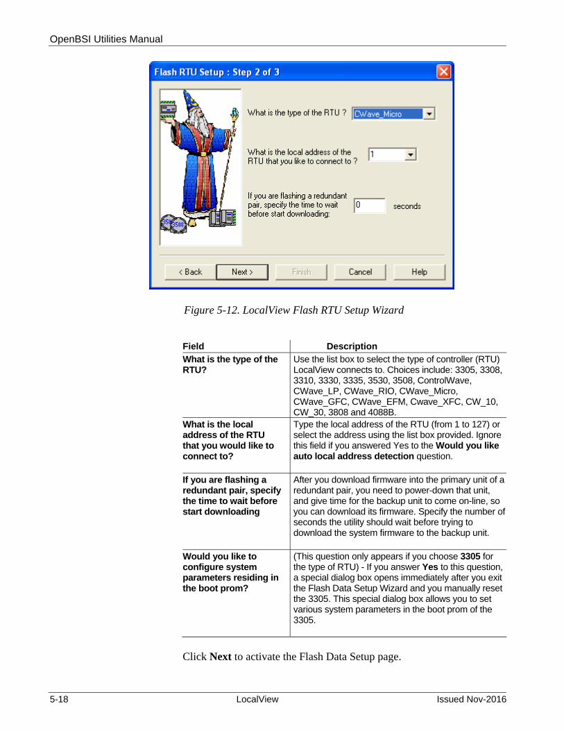
OpenBSI Utilities Manual
5-18 LocalView Issued Nov-2016
Figure 5-12. LocalView Flash RTU Setup Wizard
Field Description
What is the type of the RTU?
Use the list box to select the type of controller (RTU) LocalView connects to. Choices include: 3305, 3308, 3310, 3330, 3335, 3530, 3508, ControlWave, CWave_LP, CWave_RIO, CWave_Micro, CWave_GFC, CWave_EFM, Cwave_XFC, CW_10, CW_30, 3808 and 4088B.
What is the local address of the RTU that you would like to connect to?
Type the local address of the RTU (from 1 to 127) or select the address using the list box provided. Ignore this field if you answered Yes to the Would you like auto local address detection question.
If you are flashing a redundant pair, specify the time to wait before start downloading
After you download firmware into the primary unit of a redundant pair, you need to power-down that unit, and give time for the backup unit to come on-line, so you can download its firmware. Specify the number of seconds the utility should wait before trying to download the system firmware to the backup unit.
Would you like to configure system parameters residing in the boot prom?
(This question only appears if you choose 3305 for the type of RTU) - If you answer Yes to this question, a special dialog box opens immediately after you exit the Flash Data Setup Wizard and you manually reset the 3305. This special dialog box allows you to set various system parameters in the boot prom of the 3305.
Click Next to activate the Flash Data Setup page.

OpenBSI Utilities Manual
Issued Nov-2016 LocalView 5-19
5.7.5 Flash Data Setup Wizard
Complete the fields in the Flash Data Setup Wizard, as described, below:
Figure 5-13. LocalView Flash Data Setup Wizard
Field Description
Please enter the name of the binary file to Flash
To upgrade system firmware, you must specify the path and name of a binary (*.BIN) file on your hard disk containing the firmware. Optionally, the flash master file may include a description of the contents of the various available BIN files (see box at bottom of the dialog box). If you specify a flash master file, double-click the description of the binary file you want to download to the RTU and LocalView copies the path and name into this field. (If you do not have a flash master file, type the path and name of the binary file directly into this field.)
Location of Flash Master File
Specifies the location of the flash master file (FLASH.MST). The contents of the flash master file appear in the box at the bottom of the dialog box, and you can use them to select binary files for flash downloading. (See above). If necessary, you can use the Browse button to locate the flash master file.
Click Finish to install the specified BIN file in flash memory at the RTU.
Once the flash download begins, you will cannot shut down LocalView, unless you cancel the download, or it completes.

OpenBSI Utilities Manual
5-20 LocalView Issued Nov-2016
A window shows the progress of the flash download. If LocalView detects a mismatch in file versions, or if the type of .BIN file does not match the type of RTU, the download aborts.
Figure 5-14. Progress of Flash Download
Notes:
After you complete the flash download, remember to reset the switches on your controller to allow for normal operation.
Device Type and Version ID do NOT apply for ControlWave-series controllers. Device Type shows as “0” for these units.
If your unit is an RTU 3305, a message box pops up prior to Figure 5-14. You must physically reset the unit within 30 seconds of when you click OK in order for the 3305 to accept the system firmware upgrade. (See Section 5.7.6 for more information.)
Total number of bytes in BIN file
Progress of the flash download
Device Type does not apply for the ControlWave-series so it will be shown as 0. Network 3000 device types are:
1- 3530 series
2- 386EX RM unit
3- 386EX PM unit
4- RTU 3305
5- GFC 3308
These fields do not apply for ControlWave-series units
Path and filename of BIN file.
If necessary, click here to cancel the flash download
Number of bytes already downloaded

OpenBSI Utilities Manual
Issued Nov-2016 LocalView 5-21
5.7.6 Setting RTU Configuration Parameters in the 3305 (3305 ONLY)
If, in the Flash RTU Setup wizard, you answered Yes to the question “Would you like to configure system parameters in the boot prom?” the message box below appears.
After you click OK and manually reset the RTU, a dialog box comes up to let you configure these parameters.
Figure 5-15. RTU 3305 Flash Parameters
Field Description
Node Address Sets the local address of the locally connected RTU 3305. LocalView initially communicates using 127, which is the default.
Cold Download Baud Rate
Sets the baud rate the RTU 3305 uses for cold downloads (unit currently empty, no ACCOL load). You can only perform cold downloads on port B or D of the RTU 3305.
BSAP Slave If this RTU is part of an expanded node addressing network (EBSAP), choose Expanded and enter the EBSAP group number in Group Number; otherwise, choose Standard.
Self Test Diagnostic Message
You can configure the RTU 3305 to send self-test diagnostic messages out through Port A. Choose Enabled to allow these messages, or Disabled to inhibit these messages.

OpenBSI Utilities Manual
5-22 LocalView Issued Nov-2016
ACCOL Load If this ACCOL load is RAM Based the load only continues to run so long as you don’t reset the 3305 or the 3305 does not suffer a watchdog failure, in which case the load is lost. If a power failure occurs, the 3305 retains the load only as long as the backup battery functions. If the ACCOL load is FLASH Based the 3305 stores the ACCOL load in flash memory, and then copies it into RAM to execute. If you reset the unit or it suffers a watchdog failure, the 3305 preserves the load in flash and restarts it from scratch when you return the unit to operation.
ACCOL Flash When set to Locked prevents you from downloading a new ACCOL load into flash, unless the ACCOL flash area is empty. When set to Unlocked allows a new download into the ACCOL flash area.
Operation When set to Debug you can updump 3305 system memory. This option also disables the watchdog and real time clock correction in the 3305 and enables tracing for buffers. Set to Normal if you don’t want to perform debug operations.
ACCOL Flash Erasure When set to Enabled (and the ACCOL Flash option is set to Unlocked) immediately erases the ACCOL load currently in flash. The erasure begins as soon as you click Enabled - - NOT when you exit the dialog box. You use the ACCOL Flash Erasure feature only in the case where you erroneously download an ACCOL load without a valid communication port configured; once the download completes you cannot communicate with the unit. If this situation occurs, set ACCOL Flash Erasure to Enabled. The 3305 immediately erases the ACCOL load from flash, and automatically disables this option. Now you can download a new load.
Exit Configuration Click here to close the Configuration of Flash Memory Parameters dialog box. Depending upon selections you make (see below) the 3305 either enters Flash Download mode or Updump / Capture mode after you click this button.
Enter Flash Download mode upon exit
If you select this option, when you click Exit Configuration to exit the dialog box, the RTU 3305 enters Flash Download mode and LocalView begins to download the previously selected BIN file.
Enter Updump/Capture mode upon exit
If you select this option, when you click Exit Configuration to exit the dialog box, the RTU 3305 enters Updump/Capture mode (i.e. ready to updump system memory). Only choose this option when you want to debug hardware / firmware.
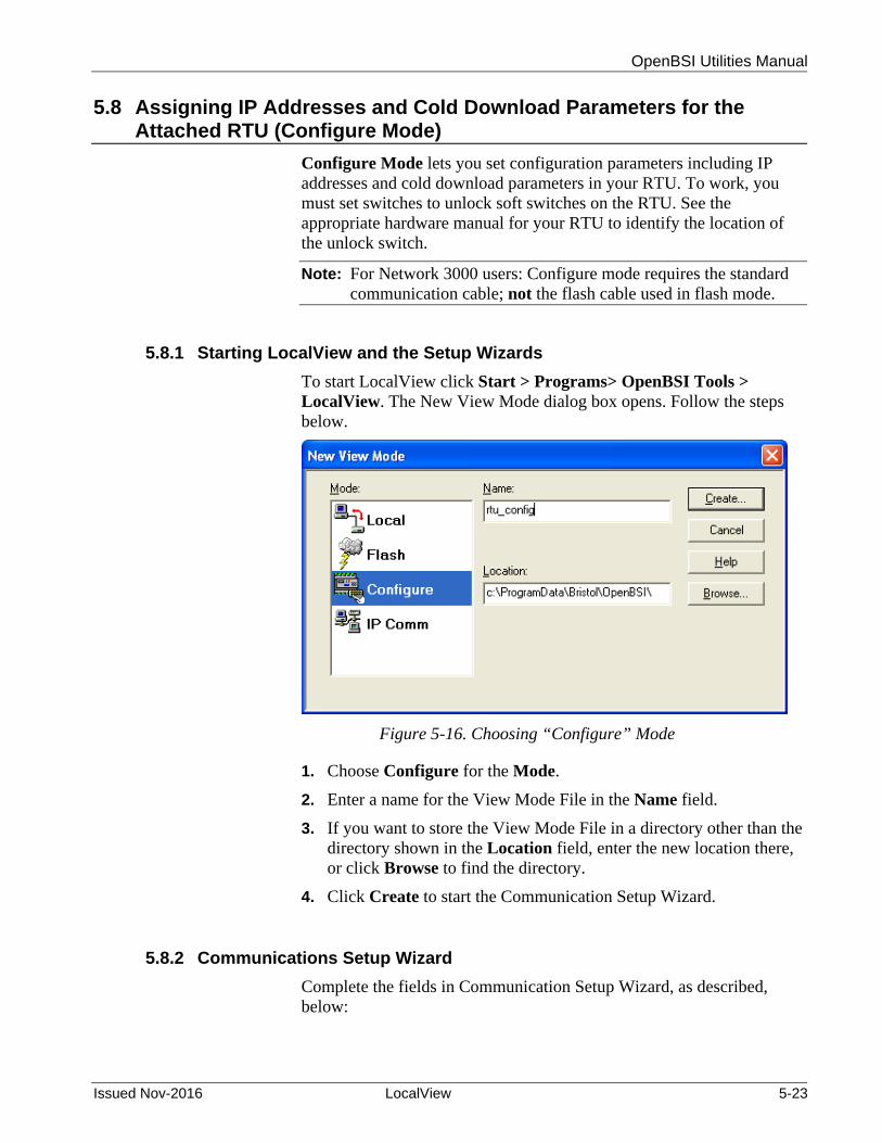
OpenBSI Utilities Manual
Issued Nov-2016 LocalView 5-23
5.8 Assigning IP Addresses and Cold Download Parameters for the Attached RTU (Configure Mode)
Configure Mode lets you set configuration parameters including IP addresses and cold download parameters in your RTU. To work, you must set switches to unlock soft switches on the RTU. See the appropriate hardware manual for your RTU to identify the location of the unlock switch.
Note: For Network 3000 users: Configure mode requires the standard communication cable; not the flash cable used in flash mode.
5.8.1 Starting LocalView and the Setup Wizards
To start LocalView click Start > Programs> OpenBSI Tools > LocalView. The New View Mode dialog box opens. Follow the steps below.
Figure 5-16. Choosing “Configure” Mode
1. Choose Configure for the Mode.
2. Enter a name for the View Mode File in the Name field.
3. If you want to store the View Mode File in a directory other than the directory shown in the Location field, enter the new location there, or click Browse to find the directory.
4. Click Create to start the Communication Setup Wizard.
5.8.2 Communications Setup Wizard
Complete the fields in Communication Setup Wizard, as described, below:

OpenBSI Utilities Manual
5-24 LocalView Issued Nov-2016
Figure 5-17. LocalView Communication Setup Wizard
Field Description
What port would you like to use?
Select the PC port into which you plug the flash cable (e.g. COM1, COM2, etc.).
Would you like auto baud rate detection
If you know which baud rate to use, answer No and specify the baud rate. Note: This does not apply for ControlWave-series RTUs.
What baud rate would you like to use?
Select the baud rate for the PC port. It must match the RTU port baud rate. Note: Does not apply for ControlWave-series RTUs.
Advanced Parameters
Click here only if you want to set parameters for more complex communications configurations, using the Advanced Communication Parameters dialog box. See page 5-7 for details on this dialog box.
Click Next to activate the IP RTU Setup page.
5.8.3 IP RTU Setup Wizard
Complete the fields in the IP RTU Setup Wizard as described, below.
Select the PC port you want to use for this connection
Specify the baud rate used for this port.

OpenBSI Utilities Manual
Issued Nov-2016 LocalView 5-25
Figure 5-18. IP RTU Setup Wizard
Field Description
What is the local address of the RTU?
Specify the local address of the RTU, which must be an integer from 1 to 127. NOTE: This must be a unique local address in your network, to allow for proper routing of alarm and RBE messages,
What is the type of the RTU?
Specify the type of controller (although there are other choices, you should choose either “3330”, “3335”, “ControlWave”, “CWave_LP”, “CWave_Micro”, “CWave_EFM” “CWave_GFC”, “CWave_XFC”, “CW_10”, “CW_30”, and “CW_35” since these controllers support IP communication).
Use an Existing Configuration (.ndf) File
Unless this box is checked, LocalView uses its own temporary NETDEF files; however, this is inconvenient when changing configuration parameters, since you want to store them in the real NETDEF files created for your network by NetView, not in the temporary files used by LocalView. Select this option to specify the actual NETDEF filename, and change the parameters in the actual NETDEF files used by NetView.
Select the name of the RTU you would like to configure
When you check Use an Existing Configuration (.ndf) File you must use this list box to specify the name of the RTU for which you want to change configuration parameters. This RTU name must exist in the NETDEF file.
What is the name of the file that contains the configuration parameters for this RTU?
When you have check Use an Existing Configuration (.ndf) File you must specify the path and name of the NETDEF file which holds configuration parameters for this RTU. (If necessary, click Browse to locate the file.)

OpenBSI Utilities Manual
5-26 LocalView Issued Nov-2016
Click Finish when complete. LocalView processes the information, and if there are no errors, it launches the Flash Configuration utility.
5.9 Setting RTU Parameters in the Flash Configuration Utility
Note: In order to use the Flash Configuration Utility to view or change parameters in a ControlWave series controller, you must have administrative privileges. For an all-new ControlWave, use the administrative username “SYSTEM” and the password “666666.”
You initially activate the Flash Configuration Utility using configure mode in LocalView. Once you use LocalView to set these parameters, and complete other system configuration, you may later modify the parameters by calling up the same utility from within NetView, (or LocalView) by right clicking on the icon for the RTU, and choosing RTU > RTU Configuration Parameters.
Figure 5-19. Starting the Flash Configuration Utility
Certain options in the Flash Configuration utility don’t require you to establish communications with the RTU, for example, writing flash data to the NETDEF file. If while the utility begins to establish communications you decide you want to use the utility offline, you can click Cancel Initialization and Continue to do that (Figure 5-20). If, for some reason, the utility cannot establish communications, you can shut down the utility if you click on Cancel Initialization and Abort.

OpenBSI Utilities Manual
Issued Nov-2016 LocalView 5-27
Figure 5-20. Cancel Initialization dialog box
Once the Flash Configuration utility establishes communication with the RTU, you can optionally specify the source for the initial parameters displayed in the utility (Figure 5-21).
Figure 5-21. Flash Configuration Loading Options dialog box
The choices for this are described below.
Field Description
Load from device This prompts you to log into the RTU. The utility then loads the current parameters from the RTU into the Flash Configuration utility pages.
Load from FCP file This prompts you to specify the location and filename of a Flash Configuration Profile (FCP) file. FCP files are files you can use to store flash parameters on the OpenBSI workstation. This simplifies your configuration because once you store these parameters in an FCP file you can optionally re-use the FCP file to load the same flash parameters into a different RTU. That way, you

OpenBSI Utilities Manual
5-28 LocalView Issued Nov-2016
don’t have to re-enter everything for each RTU. Once you specify the FCP filename, the utility loads the current parameters from the FCP file into Flash Configuration Utility pages.
Load from Network Definition File
This choice causes the utility to load flash parameters from the current NETDEF file into the pages of the utility. Note: Only choose this option if you start the Flash Configuration utility from within NetView or TechView, or LocalView in Configure mode with a specific NDF – don’t choose this if you are running LocalView in other modes (Local, IP Comm, Flash) because LocalView uses its own temporary NETDEF file in those modes which only exists during the LocalView session.
Load defaults based on RTU type
This choice causes the utility to copy some basic flash parameters into the pages of the Flash Configuration utility. These basic parameters are based on default settings for the type of RTU.
Do not show this dialog box again
If you check this box, the Loading Options dialog box does not appear again in subsequent Flash Configuration sessions, and the last loading option you choose becomes the default.
Click OK to finalize your choice and exit the dialog box. Parameters load into the Flash Configuration utility pages based on your choice, or you answer prompts to load them from the RTU or FCP file.
Note: If you want to prevent the Loading Options dialog box from appearing, right-click on the title bar of the Flash Configuration utility, and choose Settings to bring up the Settings dialog box. You can un-check the Show Loading Options dialog box at startup. You can also check Close Transfer dialog box to automatically close the transfer dialog box after a successful transfer. Click OK to exit the Settings dialog box.
The Flash Configuration utility includes different pages for different types of parameters. To access them, click on the tab for a particular page. The number of pages varies depending upon the type of controller; ControlWave controllers have more pages than Network 3000 controllers.

OpenBSI Utilities Manual
Issued Nov-2016 LocalView 5-29
Figure 5-22. Flash Configuration Utility - ControlWave
Note: The only Network 3000 controllers you can use with the Flash Configuration Utility are DPC 3330 / DPC 3335 units with PLS03 /PLX03 /PES03 /PEX03 or newer Protected Mode firmware.
Click on any of these tabs to bring up other pages of the Flash Configuration utility.
This is only useful when using NetView. It allows you to close the session with the current controller, while still leaving the current values on the various pages of the utility. This allows you to configure a different controller, without having to re-enter values in all the fields.
You must click here to sign-on with a username and password in order to access any flash parameters. (ControlWave ONLY)
This button reads the current configuration from the NETDEF files into the utility.
This button saves ALL changes to the NETDEF files.
This button reads the current configuration from the controller into the utility.
This button saves ALL changes to the controller.
This button reads the current configuration from the Flash Configuration (FCP) file.
This button saves ALL changes to the FCP file.
This button shuts down the Flash Configuration utility.

OpenBSI Utilities Manual
5-30 LocalView Issued Nov-2016
Figure 5-23. Flash Configuration Utility – Network 3000
5.9.1 Flash Configuration Utility Buttons
The Flash Configuration utility contains several buttons, primarily for read/write file operations. Some of these operations prompt you to sign on to the RTU before you can proceed. The Flash Configuration utility buttons include:
Button Description
Apply New Node Use this button only when you start the Flash Configuration utility from within NetView (since you cannot access other nodes in the Select New Node dialog box within LocalView).
This option allows you to close the session with the current controller, and then select a different controller for configuration, in the Select New Node dialog box, without reinitializing the values in the pages of the utility. A definition for the new controller must exist within the NETDEF files.
Network 3000 controllers have fewer tabs

OpenBSI Utilities Manual
Issued Nov-2016 LocalView 5-31
One application of this is for you to open a session with a new node, and then load configuration information from the NETDEF file(s) for a different node (via Read from NDF). This is useful if you want multiple nodes to share similar configurations; you can load the common configuration into the utility, and then you only need to modify the portions unique to each individual controller.
Sign On (ControlWave-series ONLY) – You must use this to sign-on to the controller with a username and password prior to reading or writing flash parameters.
Note: If you do NOT sign on, the first time you attempt a read/write operation with the controller, LocalView prevents you from doing so and prompts you to sign on.
Set Password (Network 3000-series ONLY) – Click this to open the Enter New Password dialog box. This optionally allows you to set a password which users must subsequently enter any time the Flash Configuration Utility accesses this particular controller.
This option prevents unauthorized changes to flash configuration parameters. Enter the password in the Password field, then enter it again in the Verify field and click OK. Note: LocalView does not perform password checking until it actually attempts to alter the RTU configuration parameters; at that point, LocalView requests the old password, and if it is correct, the new password takes effect.
Read From RTU
Click here to read the current configuration characteristics directly from the controller, and copy them into the pages of the Flash Configuration Utility. You can subsequently store these in the NETDEF using the Write To NDF button, to avoid the need to re-enter the same configuration details inside NetView.

OpenBSI Utilities Manual
5-32 LocalView Issued Nov-2016
Note: LocalView prompts you to sign on when you click this button, if you did not sign on previously.
Write To RTU Click here to save all entries in all pages of the Flash Configuration Utility to the controller. The utility prompts you to confirm you want to write to the flash memory.
The Flash Configuration Utility displays the progress of the save operation.
After the write operation to the ControlWave completes, the Flash Configuration Utility assesses whether or not the changes require you to reset the ControlWave. If the utility determines that you must reset it prompts you to do so.
Warning During the reset process, your controller performs no measurement or control of your process. Ensure you have backup control mechanisms in place during the reset process. Failure to take such precautions could result in injury to persons or damage to property

OpenBSI Utilities Manual
Issued Nov-2016 LocalView 5-33
Click Yes for OpenBSI to stop any currently running project and reboot the ControlWave unit immediately; changes then take effect. Click No if you want to manually reboot the unit later; changes do not take effect until the reboot. See Section 5.9.2 for information on forcing a reboot.
Read From FCP Click here to read the current configuration of this controller, as specified in a Flash Configuration Profile file (*.FCP), and copy it into the pages of the Flash Configuration Utility. You can then subsequently copy the configuration into the controller using the Write To RTU button.
Caution The Flash Configuration utility does not perform any validation checks on an FCP file when it opens it. Therefore, we recommend you do NOT attempt to edit the FCP file manually with a text editor, because you could corrupt the profile file. Recommended best practice is to edit the FCP only through the Flash Configuration utility.
Write To FCP Click here to copy all entries made in the Flash
Configuration Utility for the current controller into the Flash Configuration Profile file (*.FCP).
Read From NDF If you click here, the utility reads the current configuration of this controller as specified in NetView's NETDEF files, and copies it into the pages of the Flash Configuration Utility. This can be particularly useful in a situation where the CPU board of a controller fails, and you need to configure a replacement board. This option allows you to call up the configuration from the NETDEF, and subsequently copy it into the controller using the Write To Rtu button. Note: Only choose this option if you start the Flash Configuration utility from within NetView or TechView, or if you specify an NDF file in LocalView Configure mode (see Use an Existing Configuration (.ndf) File in Figure 5-18). Don’t choose this if you are running LocalView in other modes (Flash, IP Comm, Local) because LocalView uses its own temporary NETDEF file which only exists during the LocalView session and disappears on program exit.

OpenBSI Utilities Manual
5-34 LocalView Issued Nov-2016
Write To NDF If you click here, the utility copies all entries you made in the Flash Configuration Utility for the current controller into the current NETDEF file. This avoids the need to re-enter the same configuration information in NetView. Note: Only choose this option if you start the Flash Configuration utility from within NetView or TechView, or if you specify an NDF file in LocalView Configure mode (see Use an Existing Configuration (.ndf) File in Figure 5-18). Don’t choose this if you are running LocalView in other modes (Flash, IP Comm, Local) because LocalView uses its own temporary NETDEF file which only exists during the LocalView session and disappears on program exit.
Close Click here to shut down the Flash Configuration Utility.
5.9.2 Forcing a Reboot of the ControlWave
You can reset the ControlWave, at any time, using the Flash Configuration Utility. To do this, right-click on the title bar, and choose Reset Rtu from the pop-up menu:
Figure 5-24. Forcing a Reboot of the ControlWave
5.9.3 Flash Configuration Utility Tabs
The Flash Configuration utility contains multiple pages; you access a page by clicking on its tab. Network 3000 controllers have fewer tabs. The various tabs include:
Soft Switches - the most important of these is the BSAP local address of the controller. (See Section 5.9.4.)
Ports - this includes all communication ports on the controller - serial BSAP ports, serial IP ports (PPP), and Ethernet IP ports. Some controllers also support other port types. (See Section 5.9.5.)
IP Parameters - if this controller performs IP communications, you must configure certain parameters such as the IP address of the

OpenBSI Utilities Manual
Issued Nov-2016 LocalView 5-35
Network Host PC (NHP), UDP socket numbers, and the address of the default gateway. (See Section 5.9.6.)
Application Parameters - (ControlWave-series ONLY) - Most of these are “tuning” parameters which govern how the ControlWave executes its application (project). (See Section 5.9.7.)
Archive - (ControlWave-series ONLY) - Archive data is one portion of the historical capabilities of the ControlWave controller. It allows you to save “snapshots” of many variables at the same instant, to provide a detailed historical record of process variables at a particular moment in time. The controller stores the archive data in structures called archive files. You configure the archive feature, in part, using the ARCHIVE function block in your ControlWave project. OpenBSI Utilities such as DataView, or the Harvester can collect and display the archive data. (See Section 5.9.8.)
Audit - (ControlWave-series ONLY) - Audit logging is one portion of the historical capabilities of the ControlWave controller. It allows you to save records of when certain variables change value, as well as records of all alarms in the system. Use the Audit page to specify various parameters used to set up the Audit system. You also need to configure the AUDIT function block in your ControlWave project. (See Section 5.9.9.)
IP Routes - (ControlWave-series ONLY) - Dynamic IP routes allows the ControlWave to take messages which cannot successfully reach a particular destination address, to re-route them through a different path in the IP network. (See Section 5.9.10.)
Security - (ControlWave-series ONLY) - This page allows you to configure user accounts and privileges. (See Section 5.9.11 .)
5.9.4 Soft Switches
To reach the “Soft Switches” page, click on the “Soft Switches” tab in the Flash Configuration utility.

OpenBSI Utilities Manual
5-36 LocalView Issued Nov-2016
Figure 5-25. Soft Switches Page
Complete the fields as described below:
Field Description
Local Address
Specify the BSAP local address here, which must be an integer from 1 to 127. The default is 1. The BSAP local address is important even in non-BSAP networks to ensure proper routing of alarm and RBE messages.
EBSAP Group
Specify the EBSAP group number here; if this node does not use expanded node addressing (EBSAP), enter “0” for the group number.
Updump Enable
(Network 3000 ONLY - does NOT apply to ControlWave-series) – Emerson Support personnel occasionally use this option to help debug a problem. When you select this option, the RTU resets, and waits for a few seconds for you to press the reset button again. Rather than enter self-test mode following a crash, updump enable activates a menu on the attached PC or laptop which allows system RAM to be saved in a disk file. We call this disk file a “memory dump”.

OpenBSI Utilities Manual
Issued Nov-2016 LocalView 5-37
5.9.5 Ports
To reach the “Ports” page, click on the “Ports” tab in the Flash Configuration utility. The numbers and types of ports shown for configuration vary depending upon the type of controller.
To configure a particular port, click on its icon in the left part of the page, and the right part of the page will display the parameters for that port (which can further change depending upon the mode and how you configure the port).
Figure 5-26. Ports Page
Caution When configuring ports in the Flash Configuration Utility, exercise care regarding the port through which you are currently communicating using NetView, TechView, or LocalView. For example, if you change the baud rate for the serial port on which you are currently communicating and click “Write to RTU” all communications on that port immediately cease because you now made the baud rates incompatible with the current baud rate setting in NetView, TechView, or LocalView. If you do this accidentally, you can re-start the NetView/TechView/LocalView session using a new baud rate or you can re-establish communications by setting the “Use/Ignore Soft Switches” switch (also referred to as the “default switch”) on your CPU module to OFF, and then re-connect to one of the serial ports using the factory default baud rate setting. See your ControlWave hardware manual for details on switches and default baud rates for particular ports.
Sub-sections follow which describe the configuration for each type of port.

OpenBSI Utilities Manual
5-38 LocalView Issued Nov-2016
Ethernet Port Parameters
The Ethernet port parameters specify the IP address of this RTU's Ethernet port(s), as well as the range of IP addresses to which this RTU can send messages. To access the Ethernet Port Parameters, click the “ENET” icon in the "Ports" list box. Some controllers support up to three Ethernet ports (ENET1 through ENET3).
Figure 5-27. Ethernet Port Parameters
Field Description
IP ADDR A
This lets you specify the IP address of the Ethernet Port on the RTU, or, if this RTU is the “A” unit of a redundant pair of RTU's, the IP address for its Ethernet Port as part of the redundant pair. You must enter a unique IP address in dotted decimal format.
"P ADDR B" This lets you specify the IP address of the Ethernet Port on the “B” unit of a redundant pair of RTU's. If this RTU is NOT part of a redundant pair, specify an address of 0.0.0.0. If the RTU is part of redundant pair, you must enter a unique IP address in dotted decimal format.
IP MASK This lets you specify the range of valid IP addresses which this RTU can send messages to through this port. You must enter the mask in dotted decimal format. The default is 0.0.0.0 (all devices are reachable). Each part of the "IP MASK" can only be one of the following numbers: 255, 254, 252, 248, 240, 224, 192, 128, or 0. These values correspond to a decimal representation of the number of bits in the IP addresses of all nodes, reachable through this port, which must match exactly. If you enter anything other than "255" in a particular part of the "IP MASK"field, you must set all fields to the right to 0. Example: In the figure, above, the only IP nodes directly reachable through this port must have addresses of 10.x.y.z where x, y, and z are any integer from 0 to 255. For a more detailed explanation of IP addresses and IP masks see Chapter 1.

OpenBSI Utilities Manual
Issued Nov-2016 LocalView 5-39
BSAP Slave / EBSAP Slave Port Parameters
Use these parameters to specify the baud rate used for BSAP cold downloads through the selected serial port. For ControlWave controllers, the serial ports range from COM1 to COM11 depending upon the type of unit. For Network 3000 controllers, the serial ports are BIP 1, BIP 2, Port A through D, Port G through J.
Figure 5-28. BSAP Slave / EBSAP Slave Port Parameters
Field Description
Mode
Choose either BSAP Slave if this controller belongs to a BSAP network (or sub-network) or EBSAP Slaveif this controller belongs to an EBSAP network.
Baud Rate For Network 3000 controllers, the baud rate specified here is for cold download usage, which does not become active until you reset the unit. During all other on-line usage, the ACCOL load settings determine the baud rate, not the rate you specify here. For ControlWave-series controllers, the baud rate you enter here applies to any usage of this port. In addition, if the port already exists, changes made here are immediate, and do not require you to reset the unit.
User Mode Port Parameters
Use these parameters to configure a customized serial data link protocol. For ControlWave controllers, the serial ports range from COM1 to COM11 depending upon the type of unit. For Network 3000 controllers, the serial ports are BIP 1, BIP 2, Port A through D, Port G through J.
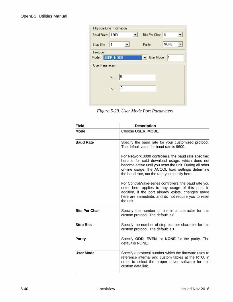
OpenBSI Utilities Manual
5-40 LocalView Issued Nov-2016
Figure 5-29. User Mode Port Parameters
Field Description
Mode
Choose USER_MODE.
Baud Rate Specify the baud rate for your customized protocol. The default value for baud rate is 9600. For Network 3000 controllers, the baud rate specified here is for cold download usage, which does not become active until you reset the unit. During all other on-line usage, the ACCOL load settings determine the baud rate, not the rate you specify here. For ControlWave-series controllers, the baud rate you enter here applies to any usage of this port. In addition, if the port already exists, changes made here are immediate, and do not require you to reset the unit.
Bits Per Char Specify the number of bits in a character for this custom protocol. The default is 8.
Stop Bits Specify the number of stop bits per character for this custom protocol. The default is 1.
Parity Specify ODD, EVEN, or NONE for the parity. The default is NONE.
User Mode Specify a protocol number which the firmware uses to reference internal and custom tables at the RTU, in order to select the proper driver software for this custom data link.

OpenBSI Utilities Manual
Issued Nov-2016 LocalView 5-41
P1 This is is a protocol-specific value which a non-standard protocol uses at RTU initialization. Its value is 4 bytes unsigned, and defaults to 0. (This field is only for non-standard, customized data links.)
P2 This is a second protocol-specific value which a non-standard protocol uses at RTU initialization. Its value is 4 bytes unsigned, and defaults to 0. (This field is only for non-standard, customized data links.)
PPP Port Parameters
PPP (Point-to-Point Protocol) ports allow serial IP communication. Use these parameters to specify the baud rate used for BSAP cold downloads through the selected serial port. For ControlWave controllers, the serial ports range from COM1 to COM11 depending upon the type of unit. For Network 3000 controllers, the serial ports are BIP 1, BIP 2, Port A through D, Port G through J.
Figure 5-30. PPP Port Parameters
Field Description
Mode
Choose PPP.
Baud Rate Specify the baud rate for serial IP Point-to-Point Protocol (PPP) communication. The default is 9600. For Network 3000 controllers, the baud rate specified here is for cold download usage, which does not become active until you reset the unit. During all other on-line usage, the ACCOL load settings determine the baud rate, not the rate you specify here. For ControlWave-series controllers, the baud rate you enter here applies to any usage of this port. In addition, if the port already exists, changes made

OpenBSI Utilities Manual
5-42 LocalView Issued Nov-2016
here are immediate, and do not require you to reset the unit.
IP ADDR Specify the IP address of this serial IP port. You must enter a unique IP address in dotted decimal format.
IP MASK This lets you specify the range of valid IP addresses which this RTU can send messages to through this port. You must enter the mask in dotted decimal format. The default is 0.0.0.0 (all devices are reachable). Each part of the IP MASK can only be one of the following numbers: 255, 254, 252, 248, 240, 224, 192, 128, or 0. These values correspond to a decimal representation of the number of bits in the IP addresses of all nodes, reachable through this port, which must match exactly. If you enter anything other than "255" in a particular part of the IP MASKfield, you must set all fields to the right to 0. Example: In the figure, above, the only IP nodes directly reachable through this port must have addresses of 10.x.y.z where x, y, and z are any integer from 0 to 255. For a more detailed explanation of IP addresses and IP masks see Chapter 1.
Server Security
This parameter only applies to ControlWave-series controllers which serve as Password Authentication Protocol (PAP) / Challenge Handshaking Authentication Protocol (CHAP) servers. Choose Plain Text (PAP) to designate this controller as a PAP Server, Encrypted (CHAP) to designate this controller as a CHAP Server, or None if you do not intend to implement CHAP or PAP. (See Chapter 1for explanations of PAP/CHAP Protocols).
Client Security This parameter only applies to ControlWave-series controllers which serve as PAP/CHAP clients. Choose Plain Text (PAP) to designate this controller as a PAP Client, Encrypted (CHAP) to designate this controller as a CHAP Client, or None if you do not intend to implement CHAP or PAP. (See Chapter 1for an explanation of PAP/CHAP Protocols).
Notes About Using PAP/CHAP on a PPP Link
You can implement either the PAP or CHAP protocol as a security measure on the PPP link. CHAP is the more secure of the two protocols. The basic configuration steps at the ControlWave are the same for both.
1. Define user accounts on the “Security” page of the Flash Configuration Utility (described later in this chapter).
2. On the “Ports” page for the PPP link, use the Client Security or Server Security choice (described above) to specify whether this ControlWave port is a client or a server, and choose the security protocol for it - PAP or CHAP. Clients initiate a request for access, and servers validate the request. If you configure more than one PPP

OpenBSI Utilities Manual
Issued Nov-2016 LocalView 5-43
port, you can configure a client on one port, and a server on another port.
3. On the “IP Parameters” page of the Flash Configuration Utility (described later), choose whichever user account you want to use for PAP/CHAP transmissions in this controller.
Modbus Port Parameters (ControlWave only)
ControlWave supports three different Modbus port parameters (GOULD MODBUS Slave, ENRON Slave, MODBUS Master. For ControlWave controllers, the serial ports range from COM1 to COM11 depending upon the type of unit.
Note: Although DPC 3330/3335 controllers support these Modbus protocols, in these units, you do not define these parameters in the Flash Configuration Utility so this section does not apply.
Figure 5-31. MODBUS Port Parameters
Field Description
Mode
Choose either GOULD MODBUS Slave, ENRON Slave, or MODBUS Master.
Baud Rate Specify the baud rate for Modbus communication. The default is 9600. The baud rate you enter here applies to any usage of this port. In addition, if the port already exists, changes made here are immediate, and do not require you to reset the unit.
Bits Per Char Specify the number of bits in a character for this protocol. If the Message Type is “ASCII” the number

OpenBSI Utilities Manual
5-44 LocalView Issued Nov-2016
of bits is 7 or 8. The default is 8. If the Message Typeis “RTU (binary)” this parameter must be 8.
Stop Bits Specify the number of stop bits per character. The default is 1.
Parity
Specify either ODD, EVEN, or NONE for the parity. The default is NONE.
Message Type
"Specify the type of data which the protocol transmits, either “RTU (binary)” or “ASCII”.
Modbus Store & Forward – Activate Store & Forward
Click this to activate the Modbus Store and Forward feature (Modbus slaves only.) See the ControlWave Designer online help for an explanation of Modbus store and forward.
BSAP Master Port Parameters (ControlWave only)
BSAP master ports allow this controller to communicate with any BSAP slave RTUs. For ControlWave controllers, the serial ports range from COM1 to COM11 depending upon the type of unit.
Note: Although DPC 3330/3335 controllers support BSAP master ports, in those units, you do not define these parameters in the Flash Configuration Utility so this section does not apply.
Figure 5-32. BSAP Master Port Parameters

OpenBSI Utilities Manual
Issued Nov-2016 LocalView 5-45
Field Description
Mode
Choose BSAP Master.
Baud Rate Specify the baud rate for this BSAP master port. The default is 9600. The baud rate you enter here applies to any usage of this port. In addition, if the port already exists, changes made here are immediate, and do not require you to reset the unit.
Low Slave Specify the lowest BSAP local address among all slave nodes on this BSAP line. Together with High Slave this address defines the range of slave node addresses for this Master port.
High Slave
Specify the highest BSAP local address among all slave nodes on this BSAP line. Together with Low Slave this address defines the range of slave node addresses for this Master port.
Generic Serial (ControlWave only)
The generic serial interface provides support for custom serial protocols you may choose to implement. For ControlWave controllers, the serial ports range from COM1 to COM11 depending upon the type of unit.
Figure 5-33. Generic Serial Port Parameters

OpenBSI Utilities Manual
5-46 LocalView Issued Nov-2016
Field Description
Mode
Choose Generic Serial.
Baud Rate Specify the baud rate for the generic serial port. The baud rate you enter here applies to any usage of this port. In addition, if the port already exists, changes made here are immediate, and do not require you to reset the unit.
Bits Per Char Specify the number of bits in a character for this protocol. This defaults to 8.
Stop Bits Specify the number of stop bits per character.
Parity
Specify either ODD, EVEN, or NONE for the parity. The default is NONE.
Buffer Size
Specify the message buffer size. This can range from 256 bytes (default) to 32,767 bytes. Internally the utility stores this as Parameter 1 for the Generic Serial Port. (OpenBSI 5.6 Service Pack 1 and newer).
Note: For more information on configuring the generic serial interface, see the ControlWave Designer online help.
Allen-Bradley DF1 Master / Slave Protocols (ControlWave only)
See the ControlWave Designer online help for details on this protocol.
Note: Although DPC 3330/3335 controllers support certain Allen-Bradley protocols, in those units, you do not define these parameters in the Flash Configuration utility.
VSAT Slave (ControlWave only)
See the ControlWave Designer online help for details on this protocol.
Note: Although DPC 3330/3335 controllers support certain VSAT slave protocol, in those units, you do not define these parameters in the Flash Configuration utility.
DNP3 Master / Slave Protocols (ControlWave only)
See the ControlWave Designer online help for details on this protocol.

OpenBSI Utilities Manual
Issued Nov-2016 LocalView 5-47
AI Net Slave Protocol (ControlWave only)
See the ControlWave Designer online help for details on this protocol.
Hex Repeater Protocol (ControlWave only)
See the ControlWave Designer online help for details on this protocol.
HART Protocol (ControlWave only)
See the ControlWave Designer online help for details on this protocol.
Note: Although DPC 3330/3335 controllers support HART protocol, in those units, you do not define these parameters in the Flash Configuration utility.
Serial EXP Rack (ControlWave only)
Use this mode to communicate with a ControlWave I/O expansion rack using an RS485 link. Requires OpenBSI 5.8 or newer.
The fields vary depending upon whether you are connected to the I/O rack itself (slave) or the host ControlWave controller (master).
See the ControlWave Designer online help for more information on this mode.
Field Description
Mode
Set to Serial EXP Rack.
Baud Rate The baud rate you enter here applies to any usage of this port. In addition, if the port already exists, changes made here are immediate, and do not require you to reset the unit.
Master Addressing: Configure these fields if this is a host ControlWave controller to the I/O expansion rack.
IP Address This is the IP address (in dotted decimal format) of aport used by the master to communicate with one or more I/O expansion rack(s). The first three bytes of the IP address must match the first three bytes of the associated slave port on each I/O expansionrack on this line. For example, if this IP address is 10.56.82.251, the first three bytes of the IP address for each I/O expansion rack on this line must be 10.56.82 and the last byte must be unique for each

OpenBSI Utilities Manual
5-48 LocalView Issued Nov-2016
I/O expansion rack. If this is a non-redundant ControlWave host, set the fourth byte of this IP address to 251. If this ControlWave host is part of a redundant pair, specify the fourth byte of the IP address to be 251 for the “A” unit or 252 for the “B” unit.
Maximum Slave Address
Set this to the maximum number of I/O expansion racks connected to the host through this port.
Slave Addressing: Configure these fields if this unit is an I/O expansion rack communicating with a host ControlWave controller using RS485.
IP Address Specify the IP address of a slave port on the I/O expansion rack which communicates with a host ControlWave controller. The first three byes of the IP address must match the first three bytes of the host ControlWave’s master IP port. The fourth byte must be unique for each slave on the line and can range from 1 to 250. If this slave rack is part of a redundant pair of I/O expansion racks, specify the fourth byte of the IP address for the “B” unit to be one more than the “A” unit. For example, if the “A” unit is 10.211.43.6, then the “B” unit must be 10.211.43.7. Never assign the “A” unit in a redundant pair a number higher than 249, since the “B” unit number cannot exceed 250.
Unit is Redundant Check this box if this unit is part of a redundant pair or I/O expansion racks.

OpenBSI Utilities Manual
Issued Nov-2016 LocalView 5-49
5.9.6 IP Parameters
To reach the “IP Parameters” page, click on the “IP Parameters” tab in the Flash Configuration utility. The numbers and types of ports shown for configuration vary depending upon the type of controller.
In this page you specify the IP addresses (in dotted decimal format) of this RTU's Network Host PC (NHP), as well as UDP port/socket information. For ControlWave-series units, you can specify additional parameters for IP routing, and communications security.
Figure 5-34. IP Parameters page
Field Description
NHP IP ADDR A
Specify the primary IP address for this RTU's Network Host PC (NHP). You must enter the address in dotted decimal format.
IP ADDR B Specify a secondary IP address for the same NHP referenced by IP ADDR A or the IP address of a redundant backup NHP. If neither of these situations apply, leave IP ADDR B blank. If you enter an address you must use dotted decimal format.
These parameters only apply to ControlWave series controllers.
These parameters apply to both ControlWave and Network 3000 controllers.

OpenBSI Utilities Manual
5-50 LocalView Issued Nov-2016
UDP IBP
Specify the UDP port number (socket number) the IP driver uses. The driver uses this value to split message traffic along different “streams”. All PC's or RTU's which you want to communicate with each other must share the same IBP number. In a sense, this value is like a common password which each node in the network must know. If you don’t enter a value, the system uses a default value from the NETDEF files. Note: The term “UDP Port” has no actual relationship with the physical communicationports.
Time Synch Specify the UDP port number (socket number) the IP driver uses for time synchronization of the RTU's. All PC's or RTU's must share this same value, or else they cannot receive time synchronization messages. In a sense, this value is like a common password which each node in the network must know. If you don’t enter a value, the system uses a default value from the NETDEF files. (Note: The term “UDP Port” has no actual relationship with the physical communication ports.)
Gateway Default G/W
Specify an IP address of a default gateway. The default gateway is an address to which any messages with destinations that are not directly reachable are sent (i.e. not in the valid address range specified by the IP mask for this node). You mustenter this address in dotted decimal format. For more information on using gateways in your network, see Chapter 1.
SNMP Disable SNMP Processing
SNMP allows monitoring and remote adjustment of certain IP parameters. For security purposes, you may want to check this box to disable this capability.
Note: SNMP equires CWP/LPS/CWR 03.00 or newer firmware or
CWM 04.00 or newer)
RIP Protocol (ControlWave only)
This section allows configuration of parameters for the Routing Internet Protocol (RIP). Beginning with ControlWave firmware CWP02.0, the ControlWave supports dynamic IP routing using the RIP protocol. A router which supports RIP essentially maintains a set of tables of IP address ranges which it can reach, either directly, or through another router. You can specify “include address ranges” and “exclude

OpenBSI Utilities Manual
Issued Nov-2016 LocalView 5-51
address ranges” for use in these tables, to avoid sending out routes to known areas in the same network.
Note: The source for this information on RIP is Douglas Comer and David Stevens, Internetworking with TCP/IP - Volumes 1 & 2 (Englewood Cliffs, NJ: Prentice Hall, 1991); Frank Derfler and Steve Rigney, TCP/IP A Survival Guide for Users (New York: MIS Press, 1998)
Each router sends a broadcast message (at periodic intervals) which includes these tables. Other routers receive the broadcast message, and determine from them, whether there is a better route to a particular IP destination, than the route stored in their own tables. If there is, they update their own tables. In this way, devices throughout the network(s) can determine the best possible route to send a message from one node to another. RIP includes safeguards to prevent looping situations where two routers each think the other router has the best route to a particular destination.
Field Description
Inclusion Addr
Specify an IP address, which the system uses with the Inclusion Mask (below) to define a range of IP addresses which this controller “advertises” that it can reach. This helps define a route that RIP broadcasts throughout the network. You can restrict this range further if you define an Exclusion Addr and Exclusion Mask.
Inclusion Mask If you enter a non-zero value in any of the Inclusion Mask fields, that indicates that the corresponding Inclusion Addr field specifies a portion of the IP address which must match exactly with every IP address on routes which this controller “advertises” in its RIP broadcasts. If you enter a zero value in any of the Inclusion Mask fields this means that RIP considers any integer (from 0 to 255) valid for that corresponding portion of the Inclusion address.
Exclusion Addr You can enter an IP address which RIP uses with the Exclusion Mask (below) to define a range of IP addresses on routes which this controller will not “advertise” in its RIP broadcasts, because they are already considered reachable, i.e. they are in the same network. You can modify this further based on the optional definitions of an Inclusion Addr and Inclusion Mask discussed above.
Exclusion Mask If you enter a non-zero value in any of the Exclusion Mask fields it means the corresponding Exclusion Addr field specifies a portion of the IP address which must exactly match with every IP address which this controller specifically excludes from its advertised routes. A zero value in any of the Exclusion Maskfields means the protocol considers any integer from (0 to 255) valid for that corresponding portion of the destination exclusion address.

OpenBSI Utilities Manual
5-52 LocalView Issued Nov-2016
Notes:
If you do not make any entries in either the Inclusion Addr/Mask or Exclusion Addr/Mask, RIP does not function.
Only devices which you configure for RIP can use the routing tables provided in the RIP broadcast messages.
Some examples for setting the inclusion and or exclusion address/mask pairs follow:
In Example #1 (Figure 5-35) Network A’s configuration supports RIP. The configurations for Gateway 1 and Gateway 2 also support RIP. Network B does not support RIP but has Gateway 1 as its default Gateway. Because of RIP, Network A knows about Gateway 2 as an alternate route to Network B, if Gateway 1 fails.
Figure 5-35. Example 1 – Routing Internet Protocol (RIP)
GATEWAY 1 10.0.0.200
10.0.1.200
172.16.0.1
172.16.0.2
172.16.0.200
172.16.1.200
ControlWaveControlWave
ControlWaveControlWave
10.0.0.1
10.0.0.2
Network A Network B
Example #1 In this arrangement, Network A knows that both GATEWAY 1 and GATEWAY 2 provide a route to Network B. Should either GATEWAY fail, traffic to Network B can be routed via the other GATEWAY.
Network A and Gateways 1&2 support RIP.Inclusion address/masks are set as follows:
Inclusion Addr: 172.16.0.0Inclusion Mask: 255.255.0.0
GATEWAY 2
Default Gateway: 172.16.0.200
Network B does NOTsupport RIP, but has GATEWAY 1 as itsdefault gateway.

OpenBSI Utilities Manual
Issued Nov-2016 LocalView 5-53
In Example #2 (Figure 5-36) the configurations for Networks A and B, as well as the Gateways all support RIP. Here we specify just an Exclusion Address and Mask for an address which isn't even on any of the two networks. In this case we choose 1.1.1.1. With this minimal exclusion range, RIP broadcasts include routes to all known addresses outside a particular Network, i.e. Network A receives information about routes to Network B, and Network B receives information about routes to Network A.
Figure 5-36. Example 2 – Routing Internet Protocol (RIP)
Dynamic IP Routing Ping (ControlWave only)
See the "IP Routes" page (Section 5.9.10) for a description of dynamic IP routing.
Field Description
Rate
This is the frequency (in milliseconds) at which the system tests an IP route (using a ping message) to verify that the connection still functions. If the test is unsuccessful (no return from the ping within the specified timeout) the test fails. If Retries is a non-zero value, the system makes that number of additional attempts to perform the ping test. If the test is still unsuccessful, the system re-routes IP traffic according to the information defined on the IP Routespage.
Timeout This is period of time (in milliseconds) after which the system declares the failure of the ping test for a given IP route.
Retries This is the number of additional ping tests the system makes after the first failure. If the total number of retries reaches this number, the system begins to re-route IP traffic.
GATEWAY 2
GATEWAY 110.0.0.200
10.0.1.200
172.16.0.1
172.16.0.2
172.16.0.200
172.16.1.200
ControlWaveControlWave
ControlWaveControlWave
10.0.0.1
10.0.0.2
Network A Network B
Example #2 - Network A, Network B, and all the gateways are configured for RIP, so that all routes between the networks are known.
Configure Exclusion Addr/Mask as follows:
Exclusion Addr: 1.1.1.1Exclusion Mask: 255.255.255.255

OpenBSI Utilities Manual
5-54 LocalView Issued Nov-2016
Challenge Protocol (ControlWave only)
ControlWave supports two standard protocols for security on PPP links: Challenge Handshaking Authentication Protocol (CHAP) and Password Authentication Protocol (PAP). These protocols operate in a client/server arrangement. We usually recommend CHAP since it provides greater security..
The CHAP (or PAP) server is a ControlWave-series controller. The CHAP (or PAP) client could be either a ControlWave-series controller, or an OpenBSI workstation.
The client must always supply a valid username/password combination in order to gain access to the server. If a ControlWave controller is the client, you just pre-configure the username and password combination and store it in flash at the unit. The ControlWave automatically transmits the username / password text string in response to a login prompt from the server.
Field Description
Default Username
This is the username which the ControlWave (PAP/CHAP client) transmits in response to a challenge message from the PAP/CHAP server. This username must be one of the user accounts defined for the ControlWave, and is sent along with the password defined for the specified user account.
5.9.7 Application Parameters
To reach the “Application Parameters” page, click the “Application Parameters” tab in the Flash Configuration utility.
These parameters apply only to ControlWave-series units configured as IP nodes.
Figure 5-37. Application Parameters page

OpenBSI Utilities Manual
Issued Nov-2016 LocalView 5-55
Field Description
CPU Goal Idle
This is a goal expressing the desired percentage of time the ControlWave CPU remains idle. The default value is 30%. If the CPU cannot meet this goal, the the system automatically adjusts the DEFAULT task period to free up CPU time.
Idle Min Ticks This is the minimum number of 1 millisecond clock ticks allowed between executions of the DEFAULT task. The default value is 2.
Minimum Idle
If the ControlWave CPU cannot maintain this percentage of free CPU time, it reports an overload exception. The default value is 5%.
Caution Exercise caution when you modify the application parameters for memory. If you make significant changes to these parameters without an understanding of how the parameters interact, you can actually reduce the amount of available memory, even though you increase the values of the parameters. If you do change these parameters, use small, incremental changes only.
Field Description
Memory Prog RAM
In kilobytes, this is the amount of memory the system reserves at startup to store the code for the ControlWave project. This value should notsignificantly exceed the amount of memory the project requires, because any unused reserved memory is unavailable for data or other purposes. Note: If the system does not have sufficient memory to hold the user requests, the system reduces the requests proportionally. This defaults to 1024k in the ControlWave and ControlWave MICRO, and 256k in the ControlWaveLP. This ranges from 10k to 1024k.
Data RAM This is the size of storage the system reserves for variables in kilobytes. This ranges from 10k to 1024k. The default is 256k in the ControlWave and ControlWave MICRO, and 64k in the ControlWaveLP. NOTE: This amount does not include historical data (audit/archive).
Retain RAM
This is the size of storage space (in kilobytes) the system reserves at startup for variables marked “RETAIN”. The system preserves the values of variables marked “RETAIN” in the event of a warm start download. Retain RAM ranges from 0k to 1024k, and defaults to 256k in the ControlWave and ControlWave MICRO, and 64k in the ControlWaveLP.

OpenBSI Utilities Manual
5-56 LocalView Issued Nov-2016
Redundancy Transfer Unit A Addr
This IP address must correspond to an Ethernet port on the A controller in a redundant pair.
Unit B Addr
This IP address must correspond to an Ethernet port on the B controller in a redundant pair.
Variations when using the ControlWave I/O Expansion Rack
For the ControlWave I/O Expansion Rack, the Application Parameters page appears slightly different. The page omits the “Memory” and “CPU” sections and includes a “Timeouts” section.
The Power Fail Timeout determines how outputs of the I/O rack operate when power is restored following a power failure, or under certain circumstances, during a restart following a CPU watchdog.
Host Comm Loss Timeout specifies how a communication failure with the host ControlWave controller affects the outputs of the I/O Rack.
For a full description of these options, please see the ControlWave I/O Expansion Rack Quick Setup Guide (document# D5122).

OpenBSI Utilities Manual
Issued Nov-2016 LocalView 5-57
5.9.8 Archive
To reach the “Archive” page, click the “Archive” tab in the Flash Configuration utility.
Note: Although most Network 3000 controllers also support Archiving, you cannot configure it from this page.
Figure 5-38. Archive page
The Archive feature is one portion of the historical capabilities of the ControlWave-series controllers. It allows the system to save “snapshots” of many variables at the same instant. This provides a detailed historical record of process variables at a particular moment in time.
Archive files are structures which hold the archive data inside the ControlWave. You can use OpenBSI Utilities such as DataView, or the Harvester to collect the archive files from the ControlWave.
The Archive page specifies various parameters that set up the Archive system.
Note: You must perform additional configuration for archiving within the ControlWave project file, using the ARCHIVE function block. See the ControlWave Designer Programmer’s Handbook (document# D5125) for details, as well as the on-line help for the ARCHIVE function block in ControlWave Designer.
To begin defining an archive file, click the New button and complete the fields as described below:
To delete an existing archive file, click on the file number in the box at the upper left of the page, then click the Delete button.

OpenBSI Utilities Manual
5-58 LocalView Issued Nov-2016
Note: Even after you click the Save to RTU button, the actual file deletion does not occur until you reset the unit.
Field Description
File Definition Number
This is a unique ID number for this archive file. It can range from 1 to 32767.
Name This is the archive file name. Use up to 8 alphanumeric characters for the name.
Records
Specify how many rows of “snapshot” data this archive file retains. For example, if you want to save 24 rows (records) enter 24 here. The size of each record determines the upper limit on the number of records. An archive file cannot exceed 74,000 bytes. This means that as the size of the defined archive record increases (based on your configuration of the number of columns, types of data, etc.) the number of records the system can save in the archive file decreases. Note: Each archive record includes 14 bytes to store the timestamp and sequence numbers, in addition to the bytes used to store the actual column data.
Columns This is the number of columns in the archive file. Each column corresponds to a particular variable in the ControlWave project. The number of columns ranges from 1 to 64.
Location Flash
When you select this, you configure the ControlWave to store all archive records in flash memory. Flash memory preserves the records in the event you reset the ControlWave, or if the unit's backup battery fails.
RAM When you select this, you configure the ControlWave to store all archive records in static RAM. If the ControlWave resets, for any reason, it only preserves archive records so long as the unit's backup battery continues to operate, or until you perform a system cold start. See the ControlWave Designer Programmer’s Handbook manual (document# D5125) for a discussion of system cold starts.
Interval 1 Min, 5 Min, 15 Min, 1 Hour, 1 Day
Only applies when the Timestamp Mode is Periodic. This specifies how often the ControlWave should take “snapshots” of data for archive records.

OpenBSI Utilities Manual
Issued Nov-2016 LocalView 5-59
Mode At Store
When you select At Store the archive system assigns a timestamp to this archive record based on the time it stored the record.
Start of Period When you select Start of Period the archive system assigns a timestamp to this archive record based on the time of the beginning of the interval.
Type Non Periodic
When you select Non Periodic, the system stores archive records when the ARCHIVE function block executes, if the criteria determined by the iiMode terminal is met. See the on-line help for the ARCHIVE function block, for details.
Periodic When you select Periodic, the system stores archive records when the ARCHIVE function block executes, and the chosen interval (either 1 minute, 5 minute, 15 minute, 1 hour, 1 day) expires. See the on-line help for the ARCHIVE function block, for details.
Column Definitions
To define a column in the archive file, click the Add button. The Archive Column Definition dialog box opens. Make entries as described, below and click OK when finished.
Figure 5-39. Archive Column Definition dialog box
If you need to modify a column after you exit the Archive Column Definition dialog box, select the column number in the list in the lower right part of the Archive page, and click Modify to re-call the dialog box.

OpenBSI Utilities Manual
5-60 LocalView Issued Nov-2016
To delete an existing column, select the column number in the list in the lower right part of the Archive page, then click Remove. The utility renumbers the remaining columns automatically.
Field Description
Column This displays the number of the column you want to define; the utility assigns column numbers sequentially; you cannot change them.
Title Enter a description for the column here. It can range from 1 to 16 characters.
Data Type
Allows you to choose the data type of the variable associated with this column. This should match the data type you configure for this variable in ControlWave Designer. Note: You determine the assignments of which variable goes with which column when you configure the ARCHIVE function block, in your ControlWave project.
Characteristics Determines the type of calculation the system performs on the collected data for this variable. Click on the Characteristics field and choose from the list box. See Table 5-1 for an explanation of the characteristics. This table includes formulas which use the following notation: (i) is the time at which the ARCHIVE function block executes and reads or “samples” the variable. (n) is the number of module executions or samples that can occur within the defined Periodic Interval e.g., with a one second Task execution and a one Hour Periodic Interval “n” is 3600. Wfactor in these formulas refers to the Weight Factor. You specify Weight Factors in the ARCHIVE function block. (See the ControlWave Designer Programmer’s Handbook (document# D5125).)
Precision Specify the numerical precision you want to use to display variables.
Table 5-1. Archive Characteristics
Characteristic Explanation
Avg for time when Wfactor2 !=0
This performs a simple sum and divide averaging calculation, but applies a weight factor to each sample as it reads the sample. Program logic sets the weight factor, as required, to control the averaging done by the module; typically you write the program logic to ensure that the variable being read is only averaged while another condition is valid. See the equation below:

OpenBSI Utilities Manual
Issued Nov-2016 LocalView 5-61
Characteristic Explanation
Arithmetic Mean Over Wfactor1
Performs a simple sum and divide average with each sample weighted by WeightFactor1. See the equation below:
Avg of Sqrt(var) for time when Wfactor2 !=0
During the periodic interval, sample the variable, take the square root of the sample, multiply it by WeightFactor2, and sum it. At the end of the interval, calculate the average square root and store the result in the archive. See the equation, below:
Sqr of (Avg of sqrt(var))
During the periodic interval, sample the variable, take the square root of the sample, multiply it by WeightFactor2 and sum it. At the end of the interval, calculate the average square root, then square it and store the result in the archive. See the equation below:
Note: The result is zero if Weight Factor 2 is zero for the entire interval.
Instantaneous Place value in log
No calculation performed. At the end of the periodic interval, simply store the current value of the variable in the archive.

OpenBSI Utilities Manual
5-62 LocalView Issued Nov-2016
Characteristic Explanation
Min observed value for period
At the end of the periodic interval, store the lowest value of the variable among all samples collected during this interval.
Max observed value from period
At the end of the periodic interval, store the highest value of the variable among all samples collected during this interval.
Place value in log, and 0 signal
At the end of the periodic interval, store the current value of the variable, and reset the variable to zero.
Integration over Wfactor2
Sum the samples taken during the periodic interval after multiplying each sample by WeightFactor 2. Perform the following calculation:
5.9.9 Audit
To reach the “Audit” page, click the “Audit” tab in the Flash Configuration utility.
Note: Although most Network 3000 controllers also support Audit, you cannot configure it from this page.
Figure 5-40. Audit page

OpenBSI Utilities Manual
Issued Nov-2016 LocalView 5-63
Audit logging is one portion of the historical capabilities of the ControlWave-series controllers. The Audit feature keeps records of when certain variables change value, as well as a record all alarms in the system. Beginning with ControlWave firmware 05.20, operator login/logout activity is also included in the Audit log. The Audit Configuration page specifies various parameters that set up the Audit feature.
Note: For the Audit feature to work, you must also configure your
ControlWave project file, using the AUDIT function block. See the ControlWave Designer Programmer’s Handbook (document# D5125) as well as the on-line help for the AUDIT function block, for details.
Field Description
Storage Location Flash
When you select this, you configure the ControlWave to store all Audit records in flash memory. Flash memory preserves the records in the event you reset the ControlWave, or if the unit's backup battery fails.
RAM When you select this, you configure the ControlWave to store all Audit records in static RAM. If the ControlWave resets, for any reason, it only preserves Audit records so long as the unit's backup battery continues to operate, or until you perform a system cold start. See the ControlWave Designer Programmer’s Handbook manual (document# D5125) for a discussion of system cold starts.
Logging Type Continuous
If you choose this, when the storage area for audit records fills up, the system overwrites (erases) the oldest records as new records come in.
Stop on Full If you choose this, when the storage area for audit records fills up, all logging stops. Note: This has no impact on the variables themselves; they continue to change; only the audit system no longer records the changes.
Sizing Number of Events
Specify the number of events the audit system logs. This value can range from 0 to 584. “0 “is the default, which means the system does not log any events.

OpenBSI Utilities Manual
5-64 LocalView Issued Nov-2016
Number of Alarms Specify the number of alarms the audit system logs. This value can range from 0 to 584. “0” is the default, which means that the system does not log any alarms.
Number of Records in the Overflow Buffer"
When you choose Flash as the storage location for the audit records, eventually the Alarm or Event flash logs fill up. When this happens, the audit system attempts to re-arrange the flash logs to make room for new records. The system temporarily stores any new incoming records during this re-arrangement procedure in the overflow buffer, until such time as there is sufficient space in the flash logs. Number of Records in the Overflow Buffer determines the size of the overflow buffer as a percentage of the full flash logs. For example, if you set Number of Records in the Overflow Buffer to 50, that means the system sizes the overflow buffer so it is large enough to hold 50% of the full Alarm and Event flash logs (or half) of the logs. We recommend that if you have a high frequency of audit record generation, that you set this value to 100.
Port Logging Master Port
Defines the only port on the ControlWave which can delete audit records from the audit logs. The Logging Master Port is only meaningful when the recording mode is Stop on Full.

OpenBSI Utilities Manual
Issued Nov-2016 LocalView 5-65
5.9.10 IP Routes
To reach the IP Routes page click the "IP Routes" tab in the Flash Configuration Utility.
Beginning with ControlWave firmware CWP02.0, you can optionally configure multiple gateways (routers) for a particular network to support dynamic IP routing.
A dynamic IP route is a range of destinations (IP addresses) and the gateways the system uses to reach them.
Gateways are essentially routers (devices with IP connections on two or more separate networks). As such, they provide a means to send messages from one network to another. You might want to think of gateways as entrance ramps to a highway.
You can configure up to four gateways to reach a particular destination address range, and you can specify up to 16 destination address ranges for a particular controller.
Since the system can send messages to a particular route by a choice of more than one gateway, the system can attempt transmission through one gateway, and if it fails, send traffic through one of the other gateways. This provides a degree of fault-tolerance in the system. (See figure, below)
Figure 5-41. IP Routes
GATEWAY
GATEWAY
GATEWAY
GATEWAY
10.0.0.202
10.0.0.201
10.0.0.203
10.0.0.200
172.16.0.1
172.16.0.2
172.16.0.3
172.16.0.4
172.16.0.5
172.16.0.6
172.16.0.200
172.16.0.201
172.16.0.202
172.16.0.203
USING MULTIPLE GATEWAYS FOR FAULT TOLERANCE
ControlWaveControlWave
ControlWaveControlWave
ControlWaveControlWave
ControlWaveControlWave
ControlWaveControlWave
ControlWaveControlWave
10.0.0.1
10.0.0.2
10.0.0.3
10.0.0.4
10.0.0.5
10.0.0.6
Network A Network B
If one gateway fails, message traffic betweennetworks 'A' and 'B' can be re-routed through one of the other three gateways.
Hardwarefailure

OpenBSI Utilities Manual
5-66 LocalView Issued Nov-2016
The system can test a particular path by using a specified ping address. The ping address can be the address of the gateway itself, or it could be the address of the destination controller.
The actual re-routing occurs only after a specified timeout expires. (See "IP Parameters" page for details.)
The “IP Routes” page (shown below) shows a typical configuration for the network depicted on the previous page. (This configuration applies for a controller that belongs to network "A" as shown on the previous page.)
Figure 5-42. IP Routes page
After you completely define a particular route, you can click on the next route number in the box in the upper left corner, to clear the various fields so you can enter information on the next route. You can define a total of 16 separate routes.
Field Description
Route x Destination IP Address
This IP Address together with its IP Mask define a range of destination IP addresses on this particular route.
IP Mask Any non-zero value in the IP Mask specifies a portion of the IP address which must match exactly for every IP address on the destination route.
Check Primary
If you check this selection, if event re-routing occurs due to a failure, the system forces a re-test of the first

OpenBSI Utilities Manual
Issued Nov-2016 LocalView 5-67
gateway (or ping address) to see if the failure still exists. This check allows traffic to return to its normal path using the first gateway when the problem no longer exists. This might be particularly important if the secondary route is slower than the primary. If you don’t check this selection, and there is a failure, re-routed traffic continues to use the secondary route, unless it too fails.
Route x Gateways IP Address 1 to IP Address 4
You must specify IP addresses for gateways that reside in the same network as the current controller. During normal operation, traffic uses the gateway 1 address, but if a failure occurs along the path for that gateway, the system attempts to re-route traffic to the next gateway (IP address 2). If that second gateway doesn’t work, then the system tries the third one, and that doesn’t work it tries the fourth gateway. If the fourth gateway fails, the system tries the first gateway again, and so on.
Route x Pings IP Address 1 to IP Address 4
For each of the four possible paths of a given route, you can optionally define a ping address for testing the route. Typically, you specify the IP address for the gateway of the other network as the ping address. Alternatively, you can specify the address of one of the destination controllers in the other network as the ping address; you might do this so the system checks for failure of one of the controllers in a redundant pair.
5.9.11 Security
To reach the Security page click the "Security" tab in the Flash Configuration Utility.
In the Security page, you create usernames and passwords for each user of this ControlWave-series controller, and you specify the features the user can use when they sign on. This allows you to set restrictions on who has access to certain features of the ControlWave.
Note: Beginning with OpenBSI 5.8, a new utility for security configuration called the Security Management Tool allows you to manage ControlWave security details from the OpenBSI workstation. If you choose to use the Security Management Tool, changes from the Security page of the Flash Configuration Utility are locked out by default, and you will see this message:

OpenBSI Utilities Manual
5-68 LocalView Issued Nov-2016
Figure 5-43. Security page
Adding a New User
A ControlWave-series controller supports up to 240 different users (previous to OpenBSI 5.8, 32 users was the maximum allowed). To add a user, first enter the user’s name (up to 16 characters long) in the “Username” field, and enter a password (up to 16 characters long) for that user in the “Password” AND “Verify” fields. (The password does not appear as you type it.)
Note: Prior to OpenBSI 5.8 Service Pack 1, some OpenBSI programs which communicated with the controller (such as DataView) only supported shorter usernames and passwords (10 characters or less for the username, 6 characters or less for the password) and UPPERCASE only for the password. If you have any OpenBSI workstations you haven’t upgraded yet, you may want to limit ControlWave usernames/passwords to conform to this. Newer OpenBSI software conforms to the ControlWave limits.
Next, to select the privileges for this user click "Custom" and then select the individual privileges in the “Privileges” list box, to highlight them. Alternatively, you can choose "Operator", "Engineer" or "Administrator" for a particular user, which automatically highlights privileges associated with those user categories. The tables, on the next page, show the privileges associated with these user categories, and list what all the various privileges mean.
When all desired privileges have been selected, click the Add button to add the user to the system.
Note: Every ControlWave-series controller has a special user called RDB_Max. This user account defines the maximum privileges allowed for RDB protocol messages coming into the

OpenBSI Utilities Manual
Issued Nov-2016 LocalView 5-69
ControlWave. (Programs such as DataView, the Harvester, etc. use RDB to request data from the ControlWave.) You cannot delete the RDB_Max user, or rename it, but you can change its privileges.
The table, below, shows the privileges associated with the Operator, Engineer, and Administrator categories:
Table 5-2. Standard User Privileges
Privilege Operator Engineer Administrator
Read Data Value
Update Data Value
Read Flash Files via FTP
Change/Del Flash Files via FTP
Read Historical Data
Change Last Read Pointers in Audit Info
Change/Delete Historical Definitions
Add / Change / Del User Security Info
Modify Soft Switches
Run Diag to read Memory
Run Diag to write Memory
Read Stat / Diag Info
Read Stat / Crash Blocks
Read Application Values
Write Application Values
Full Application Access
Add New Historical Definitions
The table, below, describes the meaning of each privilege:
Table 5-3. User Privileges
Privilege Description
Read Data Value Allows this user to read data values from this controller.
Update Data Value Alows this user to change data values in this controller.
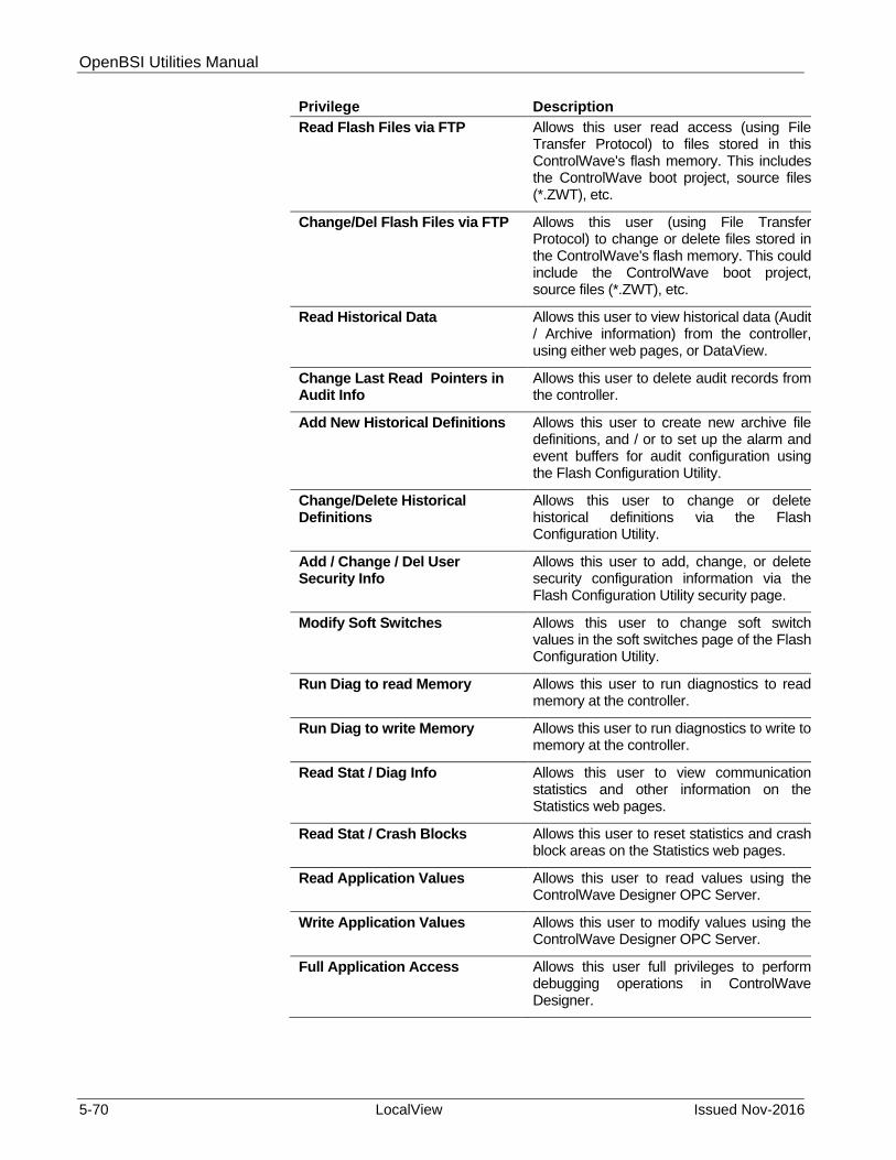
OpenBSI Utilities Manual
5-70 LocalView Issued Nov-2016
Privilege Description
Read Flash Files via FTP Allows this user read access (using File Transfer Protocol) to files stored in this ControlWave's flash memory. This includes the ControlWave boot project, source files (*.ZWT), etc.
Change/Del Flash Files via FTP Allows this user (using File Transfer Protocol) to change or delete files stored in the ControlWave's flash memory. This could include the ControlWave boot project, source files (*.ZWT), etc.
Read Historical Data Allows this user to view historical data (Audit / Archive information) from the controller, using either web pages, or DataView.
Change Last Read Pointers in Audit Info
Allows this user to delete audit records from the controller.
Add New Historical Definitions Allows this user to create new archive file definitions, and / or to set up the alarm and event buffers for audit configuration using the Flash Configuration Utility.
Change/Delete Historical Definitions
Allows this user to change or delete historical definitions via the Flash Configuration Utility.
Add / Change / Del User Security Info
Allows this user to add, change, or delete security configuration information via the Flash Configuration Utility security page.
Modify Soft Switches Allows this user to change soft switch values in the soft switches page of the Flash Configuration Utility.
Run Diag to read Memory Allows this user to run diagnostics to read memory at the controller.
Run Diag to write Memory Allows this user to run diagnostics to write to memory at the controller.
Read Stat / Diag Info Allows this user to view communication statistics and other information on the Statistics web pages.
Read Stat / Crash Blocks Allows this user to reset statistics and crash block areas on the Statistics web pages.
Read Application Values Allows this user to read values using the ControlWave Designer OPC Server.
Write Application Values Allows this user to modify values using the ControlWave Designer OPC Server.
Full Application Access Allows this user full privileges to perform debugging operations in ControlWave Designer.

OpenBSI Utilities Manual
Issued Nov-2016 LocalView 5-71
Modifying the Privileges of an Existing User
To change the privileges of an existing user, select the user’s name from the list of "Usernames" and select / de-select privileges for that user in the “Privileges” list box. When you finish making selections, click the Modify button to store the modified privileges for that user.
Cloning a User If you want to create several users with identical privileges, click on the name of the user that has the desired privileges, then click Clone.
Type the number of users you want to create in the Number of Cloned Users box, then press the [Enter] key. Users named CLONE will appear. You can then modify those users with new usernames and passwords. (OpenBSI 5.8 and newer.)
Deleting an Existing User
To delete a user from the system, select the user's name from the "Usernames" list and click the Delete button.
Notes: You cannot delete the RDB_Max user. You also cannot delete the
current user, or any user who is currently signed on to this ControlWave-series controller.
You can only modify privileges for users defined as Custom. The privileges for operators, engineers, administrators, etc. are fixed.
Importing / Exporting Security Information
If desired, you can export the configuration information for the users on this ControlWave to a *.SEC file. By default the SEC file basename is the RTU name. You can then import the SEC file into the Flash Configuration utility when you configure another ControlWave. This allows you to easily replicate the same security configuration on multiple ControlWaves.
To export a security file, click Export to Security File and provide a filename, or use the default.
To import a security file, click Import from Security File and select the SEC file.
The import/export feature requires OpenBSI 5.8 and newer.
Caution Importing security data from an SEC file overwrites any existing security entries in the Flash Configuration utility.
Unless you are an advanced user, do not attempt to edit the SEC file with a text editor. Never edit the password in a text editor because it is encrypted and will corrupt the security configuration.
When You Finish Making Security Changes
Changes you make to security occur immediately after you click Write to Rtu.
Turn the default switch ON when you finish, otherwise the special default security account (SYSTEM) remains active. For ControlWave

OpenBSI Utilities Manual
5-72 LocalView Issued Nov-2016
controllers, this is CPU switch SW1-3; for ControlWave LP controllers, this is CPU switch SW4-3, and for ControlWave MICRO controllers, this is CPU switch SW2-3.
5.10 Establishing Communications With an IP RTU (IP Comm Mode)
Notes:
This mode requires OpenBSI Version 5.2 or newer. Before you establish communications with an IP RTU, your PC
must belong to the same IP network that contains the configured IP RTU.
Every IP RTU requires at least one IP port, which could be an Ethernet Port, or a serial port running serial IP Point-to-Point Protocol (PPP).
5.10.1 Starting LocalView and the Setup Wizards
To start LocalView click Start > Programs> OpenBSI Tools > LocalView. The New View Mode dialog box opens. Follow the steps below.
Figure 5-44. Choosing “IP Comm” Mode
4. Choose IP Comm for the Mode.
5. Enter a name for the View Mode File in the Name field.
6. If you want to store the View Mode File in a directory other than the directory shown in the Location field, enter the new location there, or click Browse to find the directory.
7. Click Create to start the Communication Setup Wizard.

OpenBSI Utilities Manual
Issued Nov-2016 LocalView 5-73
5.10.2 IP Communications Setup Wizard (Step 1 of 3)
Complete the fields in Communication Setup Wizard, as described, below:
Figure 5-45. IP Communications Setup Page 1
Field Description
What is the type of the RTU?
Select, from the list, the type of controller you want to communicate with, for example “ControlWave.”
What is the Primary IP Address of the RTU?
Specify the IP address of the RTU, in dotted decimal format.
What is the Secondary IP Address of the RTU?
If the RTU has two IP ports, enter the address of the second port. If this RTU belongs to a redundant pair of RTUs, enter the address of the “B” unit of the redundant pair.
What is the local address of the RTU?
The local address is a number from 1 to 127 which describes the position of this RTU within the BSAP network. Even if it does not belong to a BSAP network, you must specify a local address, since the system uses the BSAP local address to properly route alarm messages.
Control Strategy file name:
This is the name of the ACCOL load file, or ControlWave project, associated with this RTU.

OpenBSI Utilities Manual
5-74 LocalView Issued Nov-2016
If you just want to establish IP communications, for example, to collect data from the RTU using DataView or to download a new control strategy file using the Downloader, you can click Finish at this point. If, however, you want to:
receive alarms or RBE messages from this RTU at this OpenBSI Workstation
specify a particular web page to use with this controller start a particular program via the command line after
communications start specify certain IP and communication fail-over parameters, then click Next to continue to step 2 of the dialog box.
5.10.3 IP Communications Setup Wizard (Step 2 of 3)
Complete the fields, as described below, for Step 2 of the IP Communications Setup dialog box.
Figure 5-46. IP Communication Setup Page 2
Field Description
What is the Web Access Startup Page?
This specifies the first web page the system presents when the user requests “Webpage access” to this controller. Type the path and filename of the HTML file in the field, or use the Browse button to locate it.
Enter a command line, which is run after the system starts: [If you want to execute the Internet Explorer, enter the keyword
You can optionally enter a DOS command line entry or the path of an executable (.EXE) here, which the system executes after LocalView communications start. You can use this to automatically start another program. To automatically start Internet Explorer, once communications start enter the keyword

OpenBSI Utilities Manual
Issued Nov-2016 LocalView 5-75
WEBPAGE].
WEBPAGE here.
Make this PC an Alarm Destination
When you check this, it specifies that this RTU should send any alarm messages to this OpenBSI Workstation.
Make this PC an RBE Destination
When you check this, it specifies that this RTU should send any RBE messages (if the RTU supports RBE) to this OpenBSI Workstation.
If you don’t want to leave the IP parameters at their default values, click Finish at this point, to establish communications. Otherwise, click Next, and proceed to step 3.
5.10.4 IP Communications Setup Wizard (Step 3 of 3)
Complete the fields, as described below, for Step 3 of the IP Communications Setup dialog box.
Figure 5-47. IP Communication Setup Page 3
Field Description
What is the UDP Port for the IP Driver?
Specify the UDP port number (socket number) the IP driver uses. The driver uses this value to split message traffic along different “streams”. All PC's or RTU's which you want to communicate with each other must share the same UDP port number. In a sense, this value is like a common password which each node in the network must know. If you don’t enter a value, the system uses a default value from

OpenBSI Utilities Manual
5-76 LocalView Issued Nov-2016
the NETDEF files. (Note: The term “UDP Port” has no actual relationship with the physical communication ports.) This value should never be 0.
What is the UDP Port for Time Synchs?
Specify the UDP port number (socket number) the IP driver uses for time synchronization of the RTU's. All PC's or RTU's must share this same value, or else they cannot receive time synchronization messages. In a sense, this value is like a common password which each node in the network must know. If you don’t enter a value, the system uses a default value from the NETDEF files. (Note: The term “UDP Port” has no actual relationship with the physical communication ports.) This number should never be 0.
What is the frequency of Time Synchs?
This value specifies (in seconds) how often the system sends time synchronization messages to this RTU.
Do you want to disable the sending of the Time Synch?
If you choose Yes, this RTU does not receive time synchronization messages. If you choose No, this RTU does receive time synchronization messages.
Select the Communication Fail-Over Method
If you choose Always try to establish Primary link OpenBSI always attempts to communicate with this RTU using the Primary link (Primary IP Address), unless that link fails, in which case, it tries to communicate using the Secondary link (Secondary IP Address). If you choose Stay with link that is working (Symmetric), OpenBSI always attempts to use the current working communication link (either Primary or Secondary) and then if that link fails, fails-over to the alternate link. Choose this method if the RTU belongs to a redundant pair.
Click Finish when complete. LocalView processes the information, and if there are no errors, it establishes communications.
Once you establish IP communications, you can call up other OpenBSI utilities to communicate with this RTU such as DataView, or the Downloader.

OpenBSI Utilities Manual
Issued Nov-2016 NetView 6-1
Chapter 6 – Using NetView
NetView controls communications from the PC to the RTU network. It also allows you to:
Define the characteristics of a network. Define the characteristics of an RTU. Define the characteristics of communication lines. Start and/or stop OpenBSI communications. Assign usernames and passwords for OpenBSI users. Monitor the “health” of OpenBSI communications. Make on-line changes to the network.
In This Chapter
6.1 Starting NetView .............................................................................. 6-3 6.1.1 Network Definition (NETDEF) Files ...................................... 6-4 6.1.2 Starting NETVIEW from the Command Line ........................ 6-7
6.2 Starting OpenBSI Communications ................................................. 6-7 6.2.1 Restarting a Communication Line ........................................ 6-8
6.3 Stopping OpenBSI Communications ............................................... 6-8 6.3.1 Method 1: Stop the Communication Line ............................. 6-8 6.3.2 Method 2: Close the Current NETDEF files. ........................ 6-8 6.3.3 Method 3. - Shut down NetView. .......................................... 6-8
6.4 Opening an Existing Set of NETDEF Files ...................................... 6-9 6.5 Saving Changes to Your NETDEF Files ........................................ 6-10 6.6 Erasing the Last Change Made to Your NETDEF Files ................ 6-10 6.7 Renaming the Currently Running NETDEF Files .......................... 6-10 6.8 Overview of Configuration ............................................................. 6-10 6.9 Defining an NHP and Application Parameters ............................... 6-11
6.9.1 What is A Network Host PC (NHP)? .................................. 6-11 6.9.2 Activating the System Wizard ............................................. 6-15 6.9.3 Navigating Between Pages of the System Wizard ............. 6-15 6.9.4 System Wizard: Step 1 of 3 ................................................ 6-15 6.9.5 System Wizard: Step 2 of 3 ................................................ 6-20 6.9.6 System Wizard: Step 3 of 3 ................................................ 6-25 6.9.7 Signing on to the System ................................................... 6-27 6.9.8 Signing Off .......................................................................... 6-28
6.10 Configuring OpenBSI Security ....................................................... 6-29 6.10.1 Users, Usernames, and Passwords ................................... 6-29 6.10.2 Default User (SYSTEM) ..................................................... 6-29 6.10.3 Assigning or Changing the Password of the Current User 6-30 6.10.4 Adding a New User ............................................................ 6-30 6.10.5 Modifying Passwords, Privileges for an Existing User ....... 6-32 6.10.6 Removing a User from the Security System ...................... 6-33
6.11 Viewing / Modifying Application Parameters ................................. 6-33 6.12 Viewing Other Parameters You Have Already Defined ................. 6-34 6.13 Viewing the OpenBSI Journal File ................................................. 6-35 6.14 Defining a BSAP Network .............................................................. 6-36
6.14.1 Activating the Network Wizard ........................................... 6-36 6.14.2 Navigating Between Pages of the Network Wizard............ 6-37 6.14.3 Network Wizard: Step 1 of 2 ............................................... 6-38 6.14.4 Network Wizard: Step 2 of 2 ............................................... 6-39 6.14.5 Viewing BSAP Network Parameters .................................. 6-39
6.15 Defining an IP Network .................................................................. 6-41

OpenBSI Utilities Manual
6-2 NetView Issued Nov-2016
6.15.1 Activating the Network Wizard ........................................... 6-41 6.15.2 Navigating Between Pages of the Network Wizard ........... 6-41 6.15.3 Network Wizard: Step 1 of 2 .............................................. 6-42 6.15.4 Network Wizard: Step 2 of 2 .............................................. 6-43 6.15.5 Viewing IP Network Parameters ........................................ 6-43
6.16 Defining RTUs (BSAP) .................................................................. 6-44 6.16.1 Activating the RTU Wizard ................................................. 6-45 6.16.2 Navigating Between Pages of the RTU Wizard ................. 6-46 6.16.3 RTU Wizard: Step 1 of 3 .................................................... 6-46 6.16.4 RTU Wizard: Step 2 of 3 .................................................... 6-47 6.16.5 RTU Wizard: Step 3 of 3 .................................................... 6-51 6.16.6 Modifying BSAP RTU Parameters ..................................... 6-52
6.17 Defining RTUs (IP) ......................................................................... 6-54 6.17.1 Activating the RTU Wizard ................................................. 6-54 6.17.2 Navigating Between Pages of the RTU Wizard ................. 6-55 6.17.3 RTU Wizard: Step 1 of 4 .................................................... 6-55 6.17.4 RTU Wizard: Step 2 of 4 .................................................... 6-57 6.17.5 RTU Wizard: Step 3 of 4 .................................................... 6-59 6.17.6 RTU Wizard: Step 4 of 4 .................................................... 6-61 6.17.7 Modifying IP RTU Parameters ........................................... 6-63
6.18 Defining a Communication Line for a BSAP Network ................... 6-65 6.18.1 Activating the Comm Line Wizard ...................................... 6-65 6.18.2 Navigating Between Pages of the Comm Line Wizard ...... 6-66 6.18.3 Comm Line Wizard: Step 1 ................................................ 6-66 6.18.4 Comm Line Wizard: Step 2 (BSAP and/or EBSAP Lines)6-67 6.18.5 Comm Line Wizard: Step 2 (Local BSAP Line) .................. 6-70 6.18.6 Switching the Local Line to a Different RTU ...................... 6-72 6.18.7 Specifying Dial Parameters (NetView or LocalView) ......... 6-72 6.18.8 Forcing a Hang-up of the Dial-up Line ............................... 6-74 6.18.9 Comm Line Wizard: Step 3 (Enable Port Poll Control -
OPTIONAL) ...................................................................... 6-74 6.18.10 Exiting the Comm Line Wizard ......................................... 6-76 6.18.11 Modifying the Characteristics of a BSAP Comm Line ...... 6-76 6.18.12 Modifying the Characteristics of a Local BSAP Line ........ 6-78
6.19 Defining a Communication Line for an IP Network ........................ 6-79 6.19.1 Activating the Comm Line Wizard ...................................... 6-79 6.19.2 Comm Line Wizard: Step 1 of 2 ......................................... 6-80 6.19.3 Comm Line Wizard: Step 2 of 2 ......................................... 6-81 6.19.4 Advanced Parameters ........................................................ 6-84 6.19.5 Navigating Between Pages of the Comm Line Wizard ...... 6-85 6.19.6 Exiting the Comm Line Wizard ........................................... 6-85 6.19.7 Modifying the Characteristics of an IP Comm Line ............ 6-85
6.20 Deleting A Communication Line, RTU, or Network ....................... 6-88 6.21 Monitoring the Status of OpenBSI Communications ..................... 6-88
6.21.1 Accessing the Monitor Windows ........................................ 6-88 6.21.2 Using the RTU Summary Display ...................................... 6-89 6.21.3 Resetting the RTU Statistics: ............................................. 6-90 6.21.4 Getting More Detailed Information about an RTU .............. 6-90 6.21.5 Using the RTU Details Display ........................................... 6-91 6.21.6 Using the RTU Details Display for a BSAP/EBSAP RTU: . 6-91 6.21.7 Using the RTU Details Display for an IP RTU: ................... 6-94 6.21.8 Using the Message Exchange Summary Display .............. 6-96 6.21.9 Resetting the Message Exchange Statistics: ..................... 6-97 6.21.10 Getting More Detailed Information about a Message
Exchange .......................................................................... 6-97 6.21.11 Using the Message Exchange Details Display ................. 6-97 6.21.12 Buffer Usage Summary Display ....................................... 6-99 6.21.13 Resetting the Buffer Statistics: ....................................... 6-100

OpenBSI Utilities Manual
Issued Nov-2016 NetView 6-3
6.21.14 Other Ways to View Communication Statistics .............. 6-101 6.22 RTU Communication Status Checking ........................................ 6-102
6.22.1 Activating / De-activating RTU Communication Status Checking ......................................................................... 6-102
6.23 Searching For A Particular RTU in A Large Network .................. 6-103 6.24 Starting Other Programs From Within NetView ........................... 6-104 6.25 Documenting Your Network Configuration .................................. 6-106 6.26 Setting up Proxy Access .............................................................. 6-107
6.26.1 Steps for Setting up Proxy Access ................................... 6-108 6.26.2 Steps for Setting up Proxy Direct Access (IP RTU's) ....... 6-108 6.26.3 Creating and Exporting a Proxy File ................................ 6-109 6.26.4 Importing a Proxy File ...................................................... 6-110
6.27 Sending a Time Synch/NRT (TS/NRT) Message ........................ 6-110 6.28 Deleting Archive Files and/or Audit Records .............................. 6-111
6.28.1 Deleting Historical Data .................................................... 6-111
NetView stores details of your configuration in Network Definition (NETDEF) Files. The Network Definition Files include an NDF file containing system constants and application-level parameters, as well as a set of database files (*.MDB, *.DSN, and *.LDB) which contain details about specific system components (NHPs, RTUs, communication lines, and networks).
6.1 Starting NetView
Click on Start>Programs>OpenBSI Tools>NetView.
Note: If this is the very first time you start NetView on this particular
computer, the system reminds you to register the software. Otherwise, you can only use the software for a maximum of 60 days. For more information on the registration process, see Chapter 2.
If you have named a set of NETDEF files (*.NDF, *.MDB, *.DSN, and *.LDB) with a file basename of CURRENT, it opens automatically. Otherwise, you must open a configured set of NETDEF files (see Section 6.4 Opening an Existing Set of NETDEF Files).
After you select the NETDEF files, NetView prompts you to enter a username and password to gain access to the NETDEF files. If you log on correctly, OpenBSI communications starts. For more information on this, see Section 6.9.7 Signing on to the System later in this chapter.
If you have no configured NETDEF files, you must set them up; see Section 6.8 Overview of Configuration later in this chapter.
Note: If you create an all-new set of NETDEF files, they do not yet have usernames and passwords associated with them. OpenBSI automatically creates a default user called “SYSTEM”, with no password, and full privileges. A message box, shown below,

OpenBSI Utilities Manual
6-4 NetView Issued Nov-2016
appears notifying you of this. Click OK to sign on as the SYSTEM user. NOTE: We strongly recommend that you assign a password for the SYSTEM user at a later time. (We discuss this subject later.)
Figure 6-1. Default User “SYSTEM” message box
6.1.1 Network Definition (NETDEF) Files
NetView uses a set of four (4) Network Definition (NETDEF) files to define any system. Only one such set of NETDEF files can run on the PC at any one time. The four files share the same file basename, but each has a different file extension. The NDF file; which uses an ASCII text format, includes all system-wide constants and application parameters. The remaining three files have extensions of MDB, LDB, and DSN and together form a standard database. The three database files define system components such as NHPs, communication lines, networks, and RTUs.
Note: If you ever decide you want to move your NETDEF files to a different directory, and you copy them there, you must manually edit the statement DBQ=path in the DSN file to reflect the new directory path. Otherwise, NetView uses the original path and potentially references an incorrect set of NETDEF files.
Configuring a set of NETDEF files to start automatically when NetView starts
Rename whatever NETDEF files you want to start automatically to thename CURRENT. For example, if you named your NETDEF files MYNET.NDF, MYNET.DSN, MYNET.MDB, and MYNET.LDB,rename them to CURRENT.NDF, CURRENT.DSN, CURRENT.MDB,and CURRENT.LDB, respectively. CURRENT is the default filebasename that NetView looks for upon startup. For help on renamingfiles, see Section 6.7 Renaming the Currently Running NETDEF Files.The next time NetView starts; it automatically opens the NETDEF filesnamed CURRENT.
6.1.2 Starting OpenBSI Communications When Windows Starts
You can start OpenBSI communications automatically whenever Windows starts.
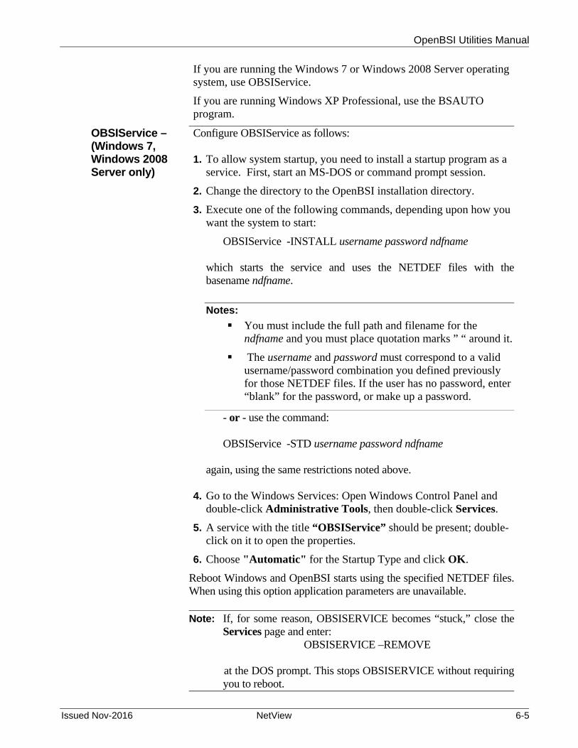
OpenBSI Utilities Manual
Issued Nov-2016 NetView 6-5
If you are running the Windows 7 or Windows 2008 Server operating system, use OBSIService.
If you are running Windows XP Professional, use the BSAUTO program.
OBSIService – (Windows 7, Windows 2008 Server only)
Configure OBSIService as follows: 1. To allow system startup, you need to install a startup program as a
service. First, start an MS-DOS or command prompt session.
2. Change the directory to the OpenBSI installation directory.
3. Execute one of the following commands, depending upon how you want the system to start:
OBSIService -INSTALL username password ndfname
which starts the service and uses the NETDEF files with thebasename ndfname.
Notes:
You must include the full path and filename for the ndfname and you must place quotation marks ” “ around it.
The username and password must correspond to a valid username/password combination you defined previously for those NETDEF files. If the user has no password, enter “blank” for the password, or make up a password.
- or - use the command: OBSIService -STD username password ndfname
again, using the same restrictions noted above. 4. Go to the Windows Services: Open Windows Control Panel and
double-click Administrative Tools, then double-click Services.
5. A service with the title “OBSIService” should be present; double-click on it to open the properties.
6. Choose "Automatic" for the Startup Type and click OK.
Reboot Windows and OpenBSI starts using the specified NETDEF files.When using this option application parameters are unavailable. Note: If, for some reason, OBSISERVICE becomes “stuck,” close the
Services page and enter: OBSISERVICE –REMOVE
at the DOS prompt. This stops OBSISERVICE without requiring
you to reboot.

OpenBSI Utilities Manual
6-6 NetView Issued Nov-2016
BSAUTO - (Windows XP Professional only)
Configure BSAUTO as follows:
1. To allow system startup, you need to install a startup program as a service. First, start an MS-DOS or command prompt session.
2. Change the directory to the OpenBSI installation directory.
3. Execute one of the following commands, depending upon how you want the system to start:
BSAUTO -INSTALL username password ndfname
which starts the service and uses the NETDEF files with thebasename ndfname. If you include spaces in the ndfname, you must place quotation marks “ “ around ndfname. If you don’t specify an ndfname, the system uses a default of CURRENT. Note: The username and password must correspond to a valid username/password combination you defined previously for thoseNETDEF files. If the user has no password, enter “blank” for thepassword, or make up a password.
- or - use the command: BSAUTO -STD username password ndfname
to run as a window with whichever set of NETDEF files youspecify with ndfname. Again, username and password must correspond to a username/password combination you previouslydefined for the NETDEF files. If you include spaces in thendfname, you must place quotation marks “ “ around ndfname. If the user has no password, enter “blank” for the password, or makeup a password.
4. Go to the Windows Services. In XP, you open Windows Control
Panel and double-click Administrative Tools, then double-click Services.
5. A service with the title “OpenBSI Automatic Startup” should be present; double-click on it to open the properties.
6. Choose "Automatic" for the Startup Type and click OK.
7. Reboot Windows and OpenBSI starts using the specified NETDEF files. When using this option application parameters are unavailable.
Note: If, for some reason, BSAUTO becomes “stuck,” close the Services dialog box (if open) then enter:
BSAUTO –REMOVE

OpenBSI Utilities Manual
Issued Nov-2016 NetView 6-7
at the DOS prompt. This stops BSAUTO without requiring you to
reboot, and also removes the “OpenBSI Automatic Startup” service from the services list.
6.1.3 Starting NETVIEW from the Command Line
To start NetView from the command line, enter:
NETVIEW filename -pt username password
Where:
filename is the name of the NETDEF (NDF) file. If you include spaces in the filename, you must place quotation marks “ “ around filename.
username is the username for that NETDEF file. password is the password for that NETDEF file.
6.2 Starting OpenBSI Communications
Notes:
In order to start communications using NetView, neither LocalView nor TechView can be running
Starting OpenBSI communications refers to starting the OpenBSI communications driver. System configuration must have been successfully completed before actual communications with the network is possible.
To start OpenBSI communications you start NetView, and then open an existing set of NETDEF files, which you previously configured (see Section 6.4 Opening an Existing Set of NETDEF Files).
If you configure a set of NETDEF files and named them CURRENT in the default OpenBSI directory, they start automatically when you start NetView.
If you do not have a configured set of NETDEF files, you must create one first. See Section 6.8 Overview of Configuration, later in this chapter, to see a list of steps which you must perform.

OpenBSI Utilities Manual
6-8 NetView Issued Nov-2016
6.2.1 Restarting a Communication Line
If a configured set of NETDEF files is already running, but communications are not currently active, the communication line may be stopped. To re-start it, click on the icon for the communication line, then choose Line>Start from the pop-up menu.
6.3 Stopping OpenBSI Communications
There are three ways to stop OpenBSI communications:
6.3.1 Method 1: Stop the Communication Line
This method keeps the current NETDEF files open; it simply shuts down communications for the selected communication line. To do this, click on the communication line icon, and press the right mouse button.
Choose Line>Stop from the pop-up menu.
6.3.2 Method 2: Close the Current NETDEF files.
This method keeps NetView running, but shuts down the current NETDEF files, and thereby stops OpenBSI communications. To do this, click File>Close.
6.3.3 Method 3: Shut down NetView.
Shutting down NetView stops all OpenBSI communications for this NHP / workstation. To do this, click File>Exit.

OpenBSI Utilities Manual
Issued Nov-2016 NetView 6-9
6.4 Opening an Existing Set of NETDEF Files
To open an existing set of NETDEF files, click on the Open File icon, or, from the menu bar, click File>Open and the Open dialog box opens. Select the desired file name and click the Open button. Note:: Opening the NDF file automatically opens the associated NETDEF database files (*.MDB, *.LDB, and *.DSN), however, this is transparent to the user.
Figure 6-2. Opening an Existing NETDEF File
After you select the NDF file, NetView prompts you to sign on with a Username and Password. The username and password must correspond to one of the username /password combinations stored in the NETDEF files. In some cases, there are no username /password combinations stored yet, in the NETDEF files. This is typically because you are either creating an all-new set of NETDEF files so these username/password combinations don’t exist yet.
For an all-new sets of NETDEF files, a message box opens and notifies you that NetView has automatically created a user named “SYSTEM” without a password. Sign on by entering “SYSTEM” in the “Username” field, and leave the “Password” field blank, then click OK.

OpenBSI Utilities Manual
6-10 NetView Issued Nov-2016
Figure 6-3. Sign On As dialog box
Caution The SYSTEM user has full administrative privileges for OpenBSI, therefore, we strongly recommend you assign a password to the SYSTEM user before you place the system in operation. Otherwise, anyone reading this book, could gain access to your NETDEF files. For information on how to define OpenBSI users, and how to assign passwords to them, see Section 6.10 Configuring OpenBSI Security
6.5 Saving Changes to Your NETDEF Files
NetView automatically saves changes to the current NETDEF files, as you edit.
6.6 Erasing the Last Change Made to Your NETDEF Files
You can reverse certain changes made to your NETDEF files if you click Edit>Undo. For example, if you accidentally delete an RTU definition, you can restore it with this command.
Note: This only works for certain changes; some changes cannot be undone.
6.7 Renaming the Currently Running NETDEF Files
Click File>Save As. The Save As dialog box opens. Enter a name for the second copy of the NETDEF files in the File Name field and click Save. This renames the current NETDEF files; the original files remain unchanged.
6.8 Overview of Configuration
In order to get your OpenBSI system up-and-running, you need to complete the following steps:
1. Start NetView to create a new set of Network Definition (NETDEF) Files. See Section 6.1 Starting NetView.

OpenBSI Utilities Manual
Issued Nov-2016 NetView 6-11
2. Define a Network Host PC (NHP) using the System Wizard, and specify application-level parameters. See Section 6.9 Defining an NHP and Application Parameters
3. Sign-on as the SYSTEM user (this allows you to proceed with additional configuration.)
4. Configure OpenBSI security. See Section 6.10 Configuring OpenBSI Security (Note: You can optionally do this later in the configuration process, if that is more convenient for you.)
5. Add a network to your NHP using the Network Wizard. You can define a BSAP network (Section 6.14), an IP network (Section 6.15), or both types of networks.)
Notes:
Beginning with OpenBSI 5.9, you can have up to 1000 BSAP networks (including sub-networks).
OpenBSI 5.5 through OpenBSI 5.8 Service Pack 2 supported up to 99 BSAP networks (including sub-networks).
Prior to OpenBSI 5.5, you could only define one BSAP network, however, you could add multiple BSAP sub-networks underneath IP RTUs.
6. Add remote process controllers (RTUs) to your network using the RTU Wizard. The type of RTU you add must match the type of network you define: you add RTUs running BSAP to the BSAP network (or sub-networks) as described in Section 6.16; you add IP RTUs to IP network(s) as described in Section 6.17.
7. Define Communication Line(s) using the Comm Line Wizard (see Sections 6.18 and 6.19).You can define up to 5000 communication lines, if necessary.
8. If you want to create additional OpenBSI workstations, you need to determine how you want to handle proxy RTU access (Section 6.26.)
6.9 Defining an NHP and Application Parameters
A Network Host PC (NHP) is the first of four basic components you need to configure in order for OpenBSI communications to function. You define it using the System Wizard.
6.9.1 What is A Network Host PC (NHP)?
A Network Host PC is any OpenBSI workstation. Typically, you connect some ControlWave or Network 3000-series remote process controllers (RTUs) to the OpenBSI workstation. When you connect the RTUs we say that the workstation serves as the “host” for those RTUs. You must define those RTUs in the Network Definition (NETDEF) Files at this NHP. Any other NHP can only gain access to these RTUs if

OpenBSI Utilities Manual
6-12 NetView Issued Nov-2016
this NHP grants access to the RTUs. Note: If an OpenBSI Workstation has no attached RTUs, we still technically consider it to be an NHP, even though it does not host any RTUs.
How do NHPs work?
In a BSAP or EBSAP network, the Network Host PC (NHP) performs the function of the network master node or level 0 node; it polls all Level 1 controllers (RTUs) for data. (See Figure 6-4.)
Figure 6-4. BSAP Network
For an IP network (and also BSAP or EBSAP networks) the Network Host PC (NHP) serves as a central location for obtaining address information about RTUs and workstations in this portion of the network. The Network Definition (NETDEF) Files, generated by NetView, store the address information for this portion of the network.
Figure 6-5. IP Network

OpenBSI Utilities Manual
Issued Nov-2016 NetView 6-13
Any OpenBSI workstation, whether or not it has attached RTUs of its own, can communicate with any RTU in the network, provided that the NHP for that RTU grants the workstation access to the RTU.
The concept of the NHP is easier to understand if you consider an analogy to the public telephone system. Most people remember a certain set of phone numbers for people they call frequently, but occasionally, they need to call someone whose number they don't know, so they call directory assistance and ask for the correct phone number. The NHP performs the exact same function as the directory assistance operator; except instead of giving out phone numbers, it provides address information, on request, for connections to any node in its section of the network.
In addition, following our same analogy, the directory assistance operator can generally do one of two things when you call for information. If you cannot call someone directly yourself, one thing the directory assistance operator can do is establish a connection for you. This same concept applies with respect to NHPs. If a particular OpenBSI Workstation needs to communicate with an RTU associated with another NHP, the other NHP can relay messages between its RTU and the inquiring workstation. We call this proxy access; see Figure 6-6:
Figure 6-6. Proxy Access
The second thing that can happen when you call for information is that the directory assistance operator just gives you the number of the person you want to call and says "call them yourself, directly!" This also applies in the case of NHPs. An NHP can grant proxy direct access to a

OpenBSI Utilities Manual
6-14 NetView Issued Nov-2016
workstation that requests access to one or more of its RTUs. That workstation can then contact the RTU directly, without the need to pass messages through the RTU's NHP. Note: Proxy direct access is only possible in IP networks, and requires the definition in the Comm Line Wizard (at the workstation requesting access) of an IP communication line for the proxy RTUs. Figure 6-7 depicts proxy direct access.
Figure 6-7. Proxy Direct Access
What are the advantages of using NHPs?
All any OpenBSI workstation in the network needs to know in order to communicate with an RTU is the IP address of the NHP for that RTU, and the RTU name. This simplifies network configuration because if the address of an RTU should change, for any reason, only its NHP needs to know. Any other workstation finds out from the NHP.
Also, because you can have multiple NHPs, each of which is responsible for a portion of your network, your supervisory control is truly distributed among multiple sites. Through proxy access, any OpenBSI workstation can communicate with RTUs belonging to any NHP in the network, provided that it knows the name of the RTU, and the IP address of the NHP for that RTU.
NHPs can be redundant
The NHP can belong to a redundant pair, in which two OpenBSI workstations share the same NHP name. If the primary of the two workstations experiences a failure, the secondary workstation assumes the NHP duties. See Section 6.9.6 - System Wizard: Step 3 of 3.
Every OpenBSI system must have at least one NHP
Every OpenBSI system requires at least one NHP. You cannot delete the NHP from your system.

OpenBSI Utilities Manual
Issued Nov-2016 NetView 6-15
6.9.2 Activating the System Wizard
To open a new set of NETDEF files, click the “New File” icon, shown at left, or click File>New. The “Save As” dialog box opens; enter a name for this set of NETDEF files, and click Save. The System Wizard activates.
6.9.3 Navigating Between Pages of the System Wizard
Click either Next or Back, whichever is appropriate.
6.9.4 System Wizard: Step 1 of 3
After you start NetView, and save your NETDEF files, the System Wizard activates so you can define various system constants, and Network Host PC (NHP) information.
Figure 6-8. System Wizard – Step 1 of 3
Most users can leave the “Advanced Parameters” at their default values.
This number defines the maximum number of RTUs your system can support. This must be at least “100.”
These only apply when defining an IP network.
A controller (node) must respond to a program (such as DataView) within this time period. If no response is received, that node is said to have “timed out.”
Click here to go to page 2.

OpenBSI Utilities Manual
6-16 NetView Issued Nov-2016
On the first page of the System Wizard, you may define the following items, or use the defaults NetView provides.
Field Description Total number of RTUs in the system
This is actually the maximum number of remote process controllers (RTUs) in your system. The default is 1000. (The minimum value for this is 100; if you have less than 100 RTUs, set the value to 100). Note: This number must include all RTUs from all networks in your system whether IP, BSAP (from any level), EBSAP, or proxy RTUs. Note: OpenBSI has an absolute limit of 4,999 for the total number of RTUs in a system.
Time out interval to wait before declaring that any message has been lost and will never return
An RTU must respond to a program (such as DataView, NetView, OpenEnterprise, etc.) within this number of seconds. If the program receives no response within this time, we say the node has “timed out.” (OpenBSI rounds this value up to the nearest 5 seconds.) Give special consideration when you specify this value in a BSAP or EBSAP network: You must consider the baud rate, number of network levels, and poll periods when you choose this value. Never make the value less than the sum of the poll periods for each level of the network, but also don’t make it too large, since that delays the initiation of a retry, if an attempt to send a message fails.
Number of attempts that must be made to send a message to a first level RTU before that RTU is declared dead or non-functional
This is the default number of times OpenBSI attempts to communicate with a directly connected (first level) BSAP RTU.
Path and filename of Network Definition File
This field displays the location and name of the NDF Network Definition (NETDEF) File created by NetView. The default location is the \ProgramData\Bristol\OpenBSI sub-directory. Note: If you copy the MDB, LDB, NDF, and DSN files to a different directory, you must manually edit the DBQ path in the DSN file to reflect the new location.
Location of ACCOL Load files
This is the location where ACCOL load files (.ACL) as well as ACCOL source files (.ACC) are ACCOL object files (.ACO) are stored on this PC. The default location is the \ProgramData\Bristol\ACCOL sub-directory. (Network 3000 only)
Path and file name for currently active BSI journal file
This is the location and name of the journal file. OpenBSI maintains this journal of important system events such as when OpenBSI was started or stopped.
Delete Journal File on Startup?
When you select Yes, OpenBSI deletes the previous journal file, and opens a new journal file, each time OpenBSI starts. When you select No, the system appends new journal entries to the existing journal
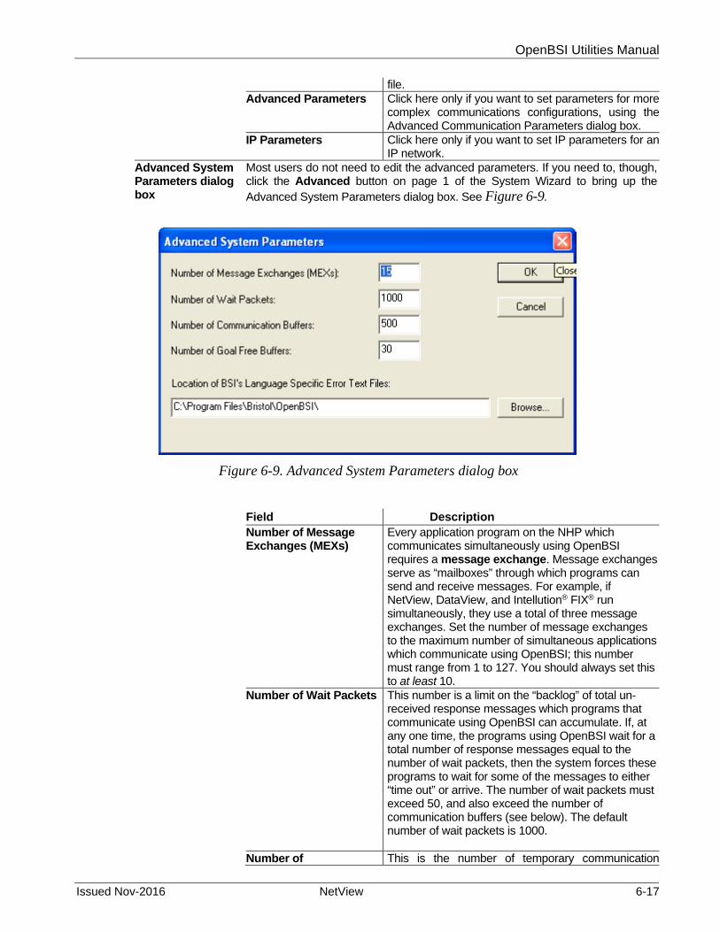
OpenBSI Utilities Manual
Issued Nov-2016 NetView 6-17
file. Advanced Parameters
Click here only if you want to set parameters for more complex communications configurations, using the Advanced Communication Parameters dialog box.
IP Parameters Click here only if you want to set IP parameters for an IP network.
Advanced System Parameters dialog box
Most users do not need to edit the advanced parameters. If you need to, though,click the Advanced button on page 1 of the System Wizard to bring up theAdvanced System Parameters dialog box. See Figure 6-9.
Figure 6-9. Advanced System Parameters dialog box
Field Description Number of Message Exchanges (MEXs)
Every application program on the NHP which communicates simultaneously using OpenBSI requires a message exchange. Message exchanges serve as “mailboxes” through which programs can send and receive messages. For example, if NetView, DataView, and Intellution® FIX® run simultaneously, they use a total of three message exchanges. Set the number of message exchanges to the maximum number of simultaneous applications which communicate using OpenBSI; this number must range from 1 to 127. You should always set this to at least 10.
Number of Wait Packets
This number is a limit on the “backlog” of total un-received response messages which programs that communicate using OpenBSI can accumulate. If, at any one time, the programs using OpenBSI wait for a total number of response messages equal to the number of wait packets, then the system forces these programs to wait for some of the messages to either “time out” or arrive. The number of wait packets must exceed 50, and also exceed the number of communication buffers (see below). The default number of wait packets is 1000.
Number of This is the number of temporary communication

OpenBSI Utilities Manual
6-18 NetView Issued Nov-2016
Communication Buffers
buffers OpenBSI uses at this PC. OpenBSI uses the buffer to hold a message that awaits transmission to an RTU, but which the system cannot send yet. The minimum number of buffers is ten. In general, the more active nodes in the network, the more buffers the system requires. Normally, you should define at least 50 buffers. The default number of buffers is 500.
Number of Goal Free Buffers
OpenBSI attempts to keep a ready supply of buffers available for general use. If the number of buffers available is less than this value, OpenBSI copies some data into local buffers of the currently running process. Set the number of goal free buffers to one half of the total number of communication buffers, or around 20, whichever is smaller.
Location of BSI's Language Specific Error Text Files
Users who purchase the OpenBSI Development Kit can edit the message text within the error text files (BSSTATUS.TXT and BSJOURN.TXT) to conform to the language requirements of their system for example, to create error messages in Spanish, French, etc. If you want to specify a different location than the default directory, you can type it in directly, or use the Browse button to locate the new directory.
IP Parameters dialog box
This dialog box configures certain parameters for your IP network, if you have one. To access IP parameters, click the IP Parameters button on page 1 of the System Wizard (Figure 6-8).
Figure 6-10. IP Parameters dialog box

OpenBSI Utilities Manual
Issued Nov-2016 NetView 6-19
Field Description UDP Port Number for IP Driver
Specify the UDP port number (socket number) the IP driver uses. The driver uses this value to split message traffic along different “streams”. All PC's or RTU's which you want to communicate with each other must share the same UDP port number. In a sense, this value is like a common password which each node in the network must know. If you don’t enter a value, the system uses a default value from the NETDEF files. (Note: The term “UDP Port” has no actual relationship with the physical communication ports.) Never set this to 0.
UDP Port Number for Time Synch
Specify the UDP port number (socket number) the IP driver uses for time synchronization of the RTU's. All PC's or RTU's must share this same value, or else they cannot receive time synchronization messages. In a sense, this value is like a common password which each node in the network must know. If you don’t enter a value, the system uses a default value from the NETDEF files. (Note: The term “UDP Port” has no actual relationship with the physical communication ports.) Never set this to 0.
Frequency of Time Synchs to IP RTUs
This value specifies (in seconds) how often the IP driver sends time synchronization messages to IP RTUs.
Remote Connection TCP Port Number for Router Process
This is the TCP port number used for communication between message routers. All PC's or RTU's must share this same value, or else they cannot use the same message router. In a sense, this value is like a common password which each node in the network must know. If you don’t enter a value, NetView uses a default value from the NETDEF files. (Note: The term “TCP port” has no actual relationship with the physical communication ports.) Note: The TCP Port Number for Router Process should never be 0.
Number of Failures before PC goes back to NHP for Proxy Access
When using Proxy Direct Access, if this PC’s attempts to send data to a proxy RTU fail, this count is the maximum number of failures the system allows before this PC must contact the RTU's NHP to see if communication parameters have changed.
Would you like this PC to access Proxy RTUs directly?
If this PC needs to communicate with RTUs associated with another NHP (i.e. proxy RTUs), and you select Yes, it means that this PC requests that the other NHP provide the actual IP addresses of the proxy RTUs. This allows direct communication between this PC and the proxy RTUs, and bypasses the NHP on future communication requests. This option only works for IP networks, and in order to function, it requires that you define a communication line at this PC (using the Comm Line Wizard) that accepts direct communication with the proxy RTUs.
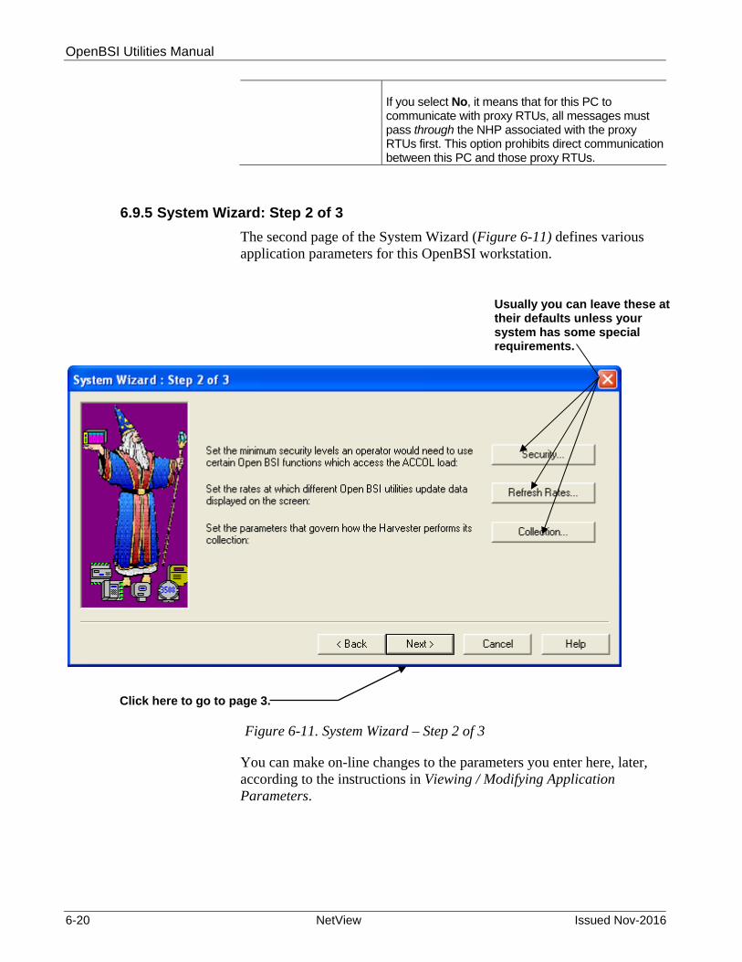
OpenBSI Utilities Manual
6-20 NetView Issued Nov-2016
If you select No, it means that for this PC to communicate with proxy RTUs, all messages must pass through the NHP associated with the proxy RTUs first. This option prohibits direct communication between this PC and those proxy RTUs.
6.9.5 System Wizard: Step 2 of 3
The second page of the System Wizard (Figure 6-11) defines various application parameters for this OpenBSI workstation.
Figure 6-11. System Wizard – Step 2 of 3
You can make on-line changes to the parameters you enter here, later, according to the instructions in Viewing / Modifying Application Parameters.
Click here to go to page 3.
Usually you can leave these at their defaults unless your system has some special requirements.

OpenBSI Utilities Manual
Issued Nov-2016 NetView 6-21
Field Description Set the minimum security levels an operator would need to use certain OpenBSI functions which access the ACCOL load:
Operators must possess the proper security level in order to access certain signals and structures in the RTU. Because various OpenBSI utilities provide access to these signals and structures, security levels in the ACCOL load restrict access to them. ACCOL supports six different levels of security access (1 to 6), as well as security level 0, which indicates no access. Operators who possess a particular security level can access any signal or structure with a security level less than or equal to their own. For example, an operator who signs on to an RTU with the security level of 3 can only access those system functions which accept security levels 1 through 3; functions which require security levels of 4 or above are inaccessible. By clicking the Security button, you can call up the Security dialog box (Figure 6-12) in which you can specify the minimum security levels needed to change certain structures.
Set the rates at which different OpenBSI utilities update data displayed on the screen:
Click Refresh Rates to call up the Refresh Rates dialog box (Figure 6-13) and specify the rate at which signal, data array, and communication statistics update on the screen. You cannot configure rates faster than one second.
Set the parameters that govern how the Harvester performs its collection:
Click the Collection push button to specify certain communication parameters for the OpenBSI Harvester software. (See Figure 6-14.)
Security dialog box
This dialog box specifies certain minimum security levels an operator requires to change certain system structures.
Figure 6-12. Security dialog box

OpenBSI Utilities Manual
6-22 NetView Issued Nov-2016
Field Description
Signal Inhibit Changes
This specifies the minimum security level an operator needs to alter the value of the manual inhibit/enable (MI/ME), control inhibit/enable (CI/CE) or alarm inhibit/enable (AI/AE) status flags for ACCOL signals. The default security level for this function is 4.
List/Recipe Changes This specifies the minimum security level an operator needs to change the configuration for the list and recipe features of DataView. The default security level for this function is 3.
Would you like to use the Username / Password Scheme?
There are two mutually-exclusive methods for defining operator security levels: Password only (default method, chosen when you select No): This method requires you to define six different passwords (also referred to as “security codes”) within each ACCOL load, one for each security level. Each password is from one to six alpha-numeric characters in length, with no spaces allowed. If using letters, you must CAPITALIZE them. For every operator who requires the same level of access, you issue them the same password. The default passwords (which you should change) appear in the table, below. Beginning with ACCOL Workbench (RM) 1.0 and ACCOL Workbench (PM) 6.2, the system automatically encrypts these passwords in the ACCOL source file, and, optionally, in the ACO/ACL file as well. Encryption provides a greater measure of security against unauthorized access.
Security Level Default Password for this Level 1 111111 2 222222 3 333333 4 444444 5 555555 6 666666
See the ACCOL Workbench User Manual (document# D4051) for more information about passwords.
Username and Password: (Optional method, chosen when you select Yes): An alternate method is to create string signals within each ACCOL load that contain usernames, passwords, and security levels. This method does not use encryption. Each string signal requires a string length of 17. The signal name must follow the format “PW.nn” where you enter “PW,” the base name, exactly as shown, and you replace “nn” with a number ranging from 01 to 32. For example, PW.01., PW.02., etc. This method reserves the first ten characters of the string for the operator's username, the next six characters for the password, and reserves the 17th character for the

OpenBSI Utilities Manual
Issued Nov-2016 NetView 6-23
operator's security level (0 to 6). You can optionally createan analog signal called “SIGNON..” that the system uses in conjunction with the EAudit Module to keep a history of which users sign on.
Click OK to save your changes and exit the Security dialog box.
Notes about Other Security Issues:
For information on configuring OpenBSI security, which restricts access to NETDEF files, as well as certain utilities such as the Alarm Router, and Signal Writer, see Section 6.10 Configuring OpenBSI Security later in this manual.
To modify application parameters, to configure networks, to configure RTUs, and to configure communication lines, you must sign on first using OpenBSI security. See Section 6.9.7. Signing on to the System.
To gain access to an RTU for various functions in DataView, or other OpenBSI tools, you need to sign-on to the RTU. See Chapter 8 for details.
For information on setting a password to prevent unauthorized changes to RTU flash configuration parameters, see Chapter 5.
For information on setting the read and write security level of individual ACCOL signals, see the ACCOL Workbench User Manual (document# D4051).
For information on setting UDP and TCP port numbers, and restricting proxy access of a workstation, see Section 6.9.4 earlier in this chapter, for details.
For details on exporting proxy files, which can grant a workstation access to the RTU's of another NHP see Section 6.26 Setting up Proxy Access.
Refresh Rates dialog box
This dialog box specifies the rates at which data updates on the screen in certain OpenBSI programs.
Figure 6-13. Refresh Rates dialog box

OpenBSI Utilities Manual
6-24 NetView Issued Nov-2016
Field Description
Signal Data Rate This is the rate (in seconds) at which DataView updates the signal/variable values it currently shows in its window. The default signal data rate is 5 seconds.
Array Data Rate This is the rate (in seconds) at which DataView updates the data array data it currently shows in its window. The default data array rate is 30 seconds.
Communication Statistics Rate
This is the rate (in seconds) at which the Remote Communication Statistics tool updates the data it currently shows in its window. The default rate is 15 seconds.
Click OK to save your changes and exit the Refresh Rates dialog box.
Collection dialog box
This dialog box specifies certain parameters for the OpenBSI Harvester software.
Figure 6-14. Collection dialog box
Field Description
Communication Retries
This specifies the number of unsuccessful attempts theHarvester makes to collect data from an RTU, before it declares an error. If the Harvester uses a modem toaccess the RTUs, this same number defines the numberof modem retries the system makes. The default value forthis parameter is 3.
Modem Retry Interval
This defines the rate at which the Harvester examines the Modem Confirm signal, to see if it is ON. The defaultvalue for this parameter is 1 second. (This is used wherean application uses a pair of signals to notify that amodem should turn ON/OFF to allow for data collection.)
Click OK to save your changes.
When you finish with the entries on Page 2 of the System Wizard, click Next to go to Page 3.
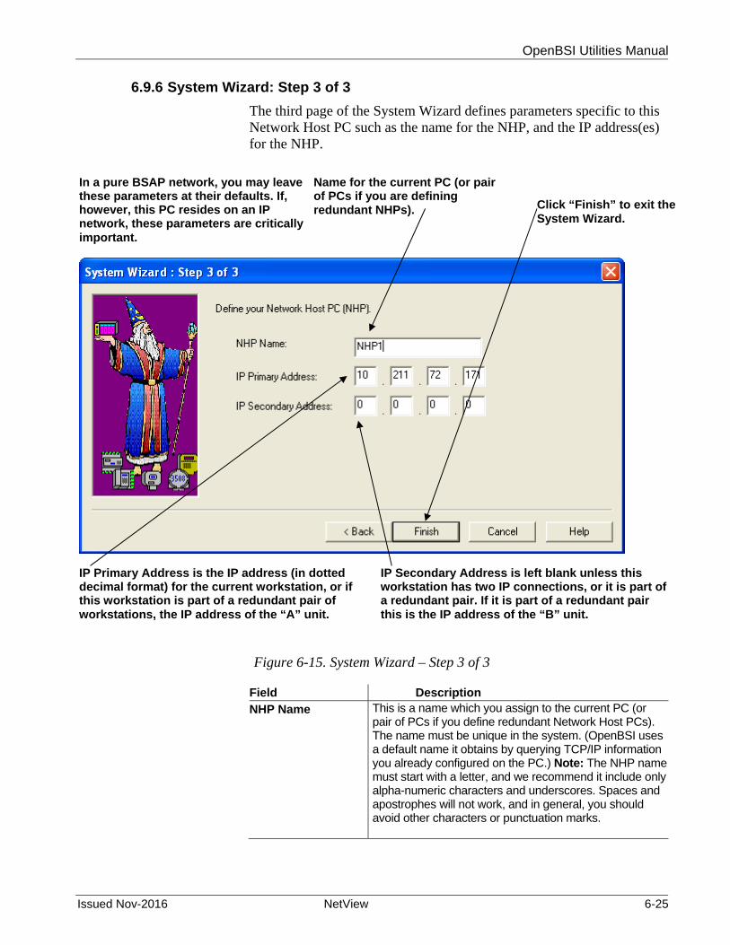
OpenBSI Utilities Manual
Issued Nov-2016 NetView 6-25
6.9.6 System Wizard: Step 3 of 3
The third page of the System Wizard defines parameters specific to this Network Host PC such as the name for the NHP, and the IP address(es) for the NHP.
Figure 6-15. System Wizard – Step 3 of 3
Field Description
NHP Name This is a name which you assign to the current PC (or pair of PCs if you define redundant Network Host PCs). The name must be unique in the system. (OpenBSI uses a default name it obtains by querying TCP/IP information you already configured on the PC.) Note: The NHP name must start with a letter, and we recommend it include only alpha-numeric characters and underscores. Spaces and apostrophes will not work, and in general, you should avoid other characters or punctuation marks.
Click “Finish” to exit the System Wizard.
In a pure BSAP network, you may leave these parameters at their defaults. If, however, this PC resides on an IP network, these parameters are critically important.
Name for the current PC (or pair of PCs if you are defining redundant NHPs).
IP Primary Address is the IP address (in dotted decimal format) for the current workstation, or if this workstation is part of a redundant pair of workstations, the IP address of the “A” unit.
IP Secondary Address is left blank unless this workstation has two IP connections, or it is part of a redundant pair. If it is part of a redundant pair this is the IP address of the “B” unit.

OpenBSI Utilities Manual
6-26 NetView Issued Nov-2016
IP Primary Address This is the primary IP address of the NHP in dotted decimal format. OpenBSI shows a default IP address it obtains by querying the PC for TCP/IP information. For BSAP networks: If you define a purely BSAP network, and you plan no IP connections at any time in the future, and you have no other workstations in your system, you can leave this field at its default. For IP networks: If this is a single non-redundant PC workstation in an IP network, with a single IP connection, enter the IP address of this PC. If this is a single non-redundant PC workstation with two IP connections, e.g. two Ethernet ports, enter the address of the primary connection. If this PC workstation belongs to a redundant pair of workstations (redundant NHPs) enter the IP address of the "A" unit of the redundant pair.
IP Secondary Address
This is the secondary IP address in dotted decimal format. For BSAP networks: If you define a purely BSAP network, and you plan no IP connections at any time in the future, you can leave this field at its default. For IP networks: If this is a single non-redundant PC workstation in an IP network, with a single Ethernet connection, leave this field blank, since there is no IP secondary address. If this is a single non-redundant PC workstation with two IP connections, e.g. two Ethernet ports, enter the address of the secondary connection. If this PC workstation belongs to a redundant pair of workstations (redundant NHPs) enter the IP address of the "B" unit of the redundant pair.
Caution This is your last opportunity to change entries in the System Wizard before you click “Finish” to exit, Once you exit the System Wizard, many of your entries cannot be changed online in NetView and if you want to change them, you must use the Off-Line Database Configuration Utility (described in Appendix B). If you need to make any changes, use the “Back” button to go to the appropriate page before you exit the wizard.
Click Finish to exit the System Wizard.
After NetView processes your System Wizard data, it presents the following message box (See Figure 6-16.)
Figure 6-16. Default User “SYSTEM” message box

OpenBSI Utilities Manual
Issued Nov-2016 NetView 6-27
This message box tells you that this new set of NETDEF files has a single user who can access it for editing purposes. That user has the name “SYSTEM” and does not require a password. When you click OK OpenBSI automatically logs you on as the SYSTEM user.
When signing on, you can leave the “SYSTEM” user with the “Password” field blank to disable OpenBSI security; allowing you to avoid the requirement to log on repeatedly during initial configuration activities.
Caution We strongly recommend that when you complete installation and configuration activities that you assign a password for the SYSTEM user. See Section 6.10 for more information on OpenBSI security.
6.9.7 Signing on to the System
You must sign on to the system before you attempt to:
Modify application parameters Define a network Define RTUs Define communication lines Assign usernames and passwords Use certain other OpenBSI tools such as Signal Writer, Alarm
Router, or DDE Server An OpenBSI workstation only allows one user to be signed on at any one time.
To activate the Sign On dialog box, click Security>Sign On -or- Click the Sign-On icon (shown at left). .
The Sign On dialog box opens.
Figure 6-17. Sign On dialog box
Enter your Username and Password and click OK.

OpenBSI Utilities Manual
6-28 NetView Issued Nov-2016
Note: If you just ran the System Wizard, and you just created an all new set of NETDEF files, there is only one user currently defined, called, “SYSTEM” and you are already signed on automatically as the SYSTEM user. Initially, the SYSTEM user has no password, so when you sign on, subsequently, you can sign on with just the “SYSTEM” Username and leave the Password field blank. We recommend, however, that you assign a password for the SYSTEM user, later. See Section 6.10 Configuring OpenBSI Security later in this chapter. Once you sign on, you are the currently logged on user, and NetView displays your username in the lower right corner of the NetView window (see Figure 6-18). In addition, NetView makes an entry in the OpenBSI journal file that indicates the time that you signed on as this user.
Figure 6-18. Currently Logged On User
6.9.8 Signing Off
To sign off the current user: Click Security> Sign Off
Another way to sign off the current user, is to sign on as a different user. To do this, click Security>Sign On, and the Sign On as dialog box opens. Specify the username and password of a different user, and click OK.
Name of the currently logged on user appears here.

OpenBSI Utilities Manual
Issued Nov-2016 NetView 6-29
6.10 Configuring OpenBSI Security
Note: The subject of OpenBSI security is entirely separate from the subject of security at the RTU. Please do not confuse the two issues.
In order to open any set of NETDEF files, you must supply the username and password associated with those NETDEF files. Because OpenBSI communications requires NETDEF files, and because most OpenBSI utilities require active communications, this prevents unauthorized users from starting the OpenBSI network, and running the various OpenBSI utilities that use it.
6.10.1 Users, Usernames, and Passwords
We call any person who logs into the OpenBSI system a user. OpenBSI identifies each user by their Username and Password
combination. Although OpenBSI does not enforce a limit on the number of users,
only one user can be logged onto an OpenBSI workstation at any one time.
A username or password consists of any combination of up to 16 alpha-numeric characters (letters and numbers). You cannot include spaces within a username or password.
Passwords are case sensitive, i.e. OpenBSI considers the password abc123, and the password ABC123 to be different passwords, even though you spell them the same.
Caution We strongly recommend that you configure OpenBSI security. Beginning with OpenBSI Version 5.3, however, if you choose to leave your OpenBSI system without security, you can do so by not assigning any password to the default user SYSTEM. When the default user SYSTEM has no password, you can start NetView automatically, without any prompt for a password.
6.10.2 Default User (SYSTEM)
When you create a new set of NETDEF files, using the System Wizard, NetView automatically creates a default user named “SYSTEM” for the new set of NETDEF files, and displays the message box shown in Figure 6-16.
The SYSTEM user has full administrative privileges for OpenBSI, including the right to add, modify, or remove users from the system. Initially, the username SYSTEM does not include an associated password, so it is important that you assign one.
Note: If you do not assign a password to the SYSTEM user, NetView operates as if there is no security, and automatically starts without prompting you for a username/password.

OpenBSI Utilities Manual
6-30 NetView Issued Nov-2016
6.10.3 Assigning or Changing the Password of the Current User
1. To change the password of the currently logged on user, for example, the “SYSTEM” user, click Security>Change Password. The Change Password dialog box opens (see Figure 6-19.)
Figure 6-19. Changing a Password
2. Enter the current password in the Old Password” field (if you haven’t defined one yet, as is initially the case with the SYSTEM user, leave the Old Password field blank).
3. Passwords consist of any combination of up to 16 alphanumeric characters (letters and numbers), and are case sensitive. Enter the new password in both the New Password and Confirm New Password fields, and then click OK.
Note: If the Security>Change Password menu item appears “grayed out,” this indicates that either the currently logged on user does not have privilege to change their password, or that some process other than NetView started OpenBSI.
6.10.4 Adding a New User
Note: You must be log on as an Administrator in order to add a new user. (The SYSTEM user is, by default, an Administrator.)
1. To define a new user, click Security> Security Maintenance. The Security Maintenance dialog box opens. Note: If the menu selection is “grayed out” it either means you did not log on as an Administrator, or some process other than NetView started OpenBSI.
2. Click the Add button. The Add New User dialog box opens.
3. Complete the fields as described, below, then click OK.

OpenBSI Utilities Manual
Issued Nov-2016 NetView 6-31
Figure 6-20. Add New User dialog box
Field Description User Username
The name of this user. Usernames consist of any combination of up to 16 alphanumeric characters. You cannot include spaces in a username.
Description (Optional) – Enter up to 49 characters to describe this user.
Password The user’s password. Enter any combination of up to 16 alphanumeric characters. Passwords are case sensitive. You cannot include spaces in a password.
Confirm Password You must enter the exact same password here, to confirm the correct spelling, and case.
Privileges Operator
OpenBSI allows Operators to view the RTU network, and start utilities such as DataView. If you allow it, they can also change their own passwords.
Engineer OpenBSI allows engineers to modify the RTU network, run all OpenBSI utilities, and modify application parameters. Engineers can also

OpenBSI Utilities Manual
6-32 NetView Issued Nov-2016
acknowledge alarms and configure collections. If you allow it, they can also change their own passwords.
Administrator OpenBSI allows administrators all the privileges of an engineer, plus they can add, remove, and modify users through the Security Maintenance dialog box.
General Do not use password for this user
If you check this box, this user has no password, only a username. When this user logs on, they leave the password field blank. We recommend you limit this option to users with operator privileges or less.
User must change password at next logon
If you check this box, the next time this user logs on, OpenBSI prevents them from doing anything until they change their password using the Change Password dialog box.
User cannot change its password
If you check this box, OpenBSI does not allow this user to change their password. If their password needs to be changed, an Administrator must make the change.
Disable user If you check this box, OpenBSI prevents this user from logging on, but keeps their security configuration in the system. You can re-instate their log-in privileges at a later time, if you un-check this box.
Lock out user after x unsuccessful sign on tries
If you check this box, OpenBSI prevents a user from logging on after the specified number of login failures. You can specify between 3 and 15 login attempts for the user.
6.10.5 Modifying Passwords, Privileges for an Existing User
To change the password, privileges, description, or general parameters for an existing user either click on the name of the user in the Security Maintenance dialog box, then click Modify, or double-click on the selected user’s name. The Modify User’s Security Information dialog box opens. This dialog box is identical to the Add New User dialog box, except that the user’s name cannot be changed. (For information on the other fields in the dialog box, see the descriptions for the Add New User dialog box, earlier in this section.)

OpenBSI Utilities Manual
Issued Nov-2016 NetView 6-33
Figure 6-21. Security Maintenance dialog box
Note: If, for some reason, you do want to change the name of a user, you must remove that user from the system, and then add them again.
6.10.6 Removing a User from the Security System
If, for some reason, you want to permanently remove a user from the security system, for example, if they are leaving the company, click on the name of the user in the Security Maintenance dialog box, then click Remove.
Notes:
You cannot remove the currently logged on user. If you want to temporarily disable a user’s login privileges, but keep
them in the Security system, for example, while someone is on an extended leave of absence, use the Disable user option in the Modify User’s Security Information dialog box.
6.11 Viewing / Modifying Application Parameters
You initially define application parameters for OpenBSI from the secondpage of the System Wizard. You can view these application parameters from most OpenBSI tools(DataView, Downloader, Remote Communication Statistics Tool, etc.) byclicking on the icon at left.

OpenBSI Utilities Manual
6-34 NetView Issued Nov-2016
If you need to modify these parameters, you must edit them from within NetView. To do this:
1. Open your set of NETDEF files.
2. Sign-on to the system.
3. Call up the OpenBSI Application Parameters dialog box. To do this click the application parameters icon (shown above) or click Edit>Application Parms from the menu bar. The OpenBSI Application Parameters dialog box consists of multiple pages that you access through tabs. Each page corresponds to the same application parameters defined in the System Wizard.
Figure 6-22. OpenBSI Application Parameters dialog box
Note: If you ever choose to move your NETDEF files to a different place on your PC, you must manually edit the DBQ path specified in the DSN file to reflect the new location.
6.12 Viewing Other Parameters You Have Already Defined
In NetView, you can view the configuration information on the networks, RTUs, and communication lines you already defined.

OpenBSI Utilities Manual
Issued Nov-2016 NetView 6-35
Figure 6-23. Viewing Configuration Information
To view this information, click on the icon for the network, communication line, or RTU you want information about, and NetView displays the information on the right-hand panes of the NetView window.
Much of the data in these panes consists of statistics about communications.
For information on the various statistics and status flags see later sections of this chapter, beginning with Section 6.21.
6.13 Viewing the OpenBSI Journal File
The OpenBSI journal file records various events which occur in the system, such as when the system starts or stops, when a user signs on, etc. To view the contents of the journal file, click on the icon, shown at left, or, from the menu bar, click View>Journal.
You can also search for journal entries concerning particular system tasks, if you click in the menu bar on View> Select Task, while the journal file is visible, and then enter the task name in the Filter dialog box.
Click on the icon, and information is displayed for it, at right.

OpenBSI Utilities Manual
6-36 NetView Issued Nov-2016
Figure 6-24. Journal File
6.14 Defining a BSAP Network
A network (either BSAP or IP) is one of the four basic components you must define for an OpenBSI communications system to function. You define your network, using the Network Wizard, only after you define your NHP.
6.14.1 Activating the Network Wizard
There are two ways to activate the Network Wizard:
One way is to right click on the NHP, and select Add>Network from the pop-up menu.
Figure 6-25. Starting the Network Wizard – Method 1
The other way to activate the Network Wizard is to first click View>Toolbox from the menu bar. This activates the Toolbox. From the Toolbox (see Figure 6-26) drag the BSAP network symbol over to the NHP icon. This activates the Network Wizard.
Right-click on the NHP, then choose Add>Network

OpenBSI Utilities Manual
Issued Nov-2016 NetView 6-37
Figure 6-26. Starting the Network Wizard – Method 2
Either of these methods starts the Network Wizard.
Notes:
A BSAP network must use the NHP as its network master. The BSAP network supports up to six network levels.
If necessary, you can add a BSAP sub-network underneath an IP RTU. In that case the network master for the BSAP sub-network is still the NHP, and the IP RTU is the only level 1 node for that sub-network. The BSAP RTUs, in this case, only exist on network level 2 through 6. This limits the BSAP sub-network to five network levels for this scenario.
Prior to OpenBSI 5.5, you could only have one BSAP network in your system, but OpenBSI allowed BSAP subnets underneath an IP RTU. OpenBSI 5.5 (and newer versions) allow you to define multiple BSAP networks in the same system, as well as BSAP subnets. You can define a maximum of 99 BSAP networks (including subnets).
OpenBSI treats each BSAP network, and any BSAP sub-network, as a separate, independent structure. Because they are separate structures, you can re-use the same BSAP local address for a level 1 node in each separate BSAP network or sub-network.
6.14.2 Navigating Between Pages of the Network Wizard
Click on either the Next or Back button, whichever is appropriate.
Drag this symbol over to the NHP icon.

OpenBSI Utilities Manual
6-38 NetView Issued Nov-2016
6.14.3 Network Wizard: Step 1 of 2
The first page of the Network Wizard defines the type of network (in this case we define a BSAP network), and the name of the network.
Figure 6-27. Network Wizard – Step 1 of 2
Complete the fields as described, below:
Field Description Enter a name for the Network
Provide a name for the network. It doesn't really matter what you name it, so long as the name is unique in the system.
Choose the Network Type
Choose BSAP Network as the Network Type. Note: If you activate the Network Wizard using the Toolbox, the wizard chooses BSAP Network for you.
Define how long to wait for a response to a message sent to an RTU in this network (Message Time-out Period)
An RTU must respond to a program (such as DataView, NetView, OpenEnterprise, etc.) within this number of seconds. If the program receives no response within this time, we say the node has “timed out.” (OpenBSI rounds this value up to the nearest 5 seconds.) Give special consideration when you specify this value in a BSAP or EBSAP network: You must consider the baud rate, number of network levels, and poll periods when you choose this value. Never make the value less than the sum of the poll periods for each level of the network, but also don’t make it too large, since that delays the initiation of a retry, if an attempt to send a message fails. Note: You need only alter this time out period if you want to specify a timeout period for this network which is different from the system-wide default timeout period you entered in the System Wizard.
Click Next to go to the second page of the Network Wizard.
Enter a name for the BSAP network. It must be unique in this OpenBSI system.
Click here to go to page 2.
Choose “BSAP Network.”

OpenBSI Utilities Manual
Issued Nov-2016 NetView 6-39
6.14.4 Network Wizard: Step 2 of 2
On the second page of the Network Wizard, you need to define the size of your BSAP network.
Figure 6-28. Network Wizard – Step 2 of 2
Field Description Enter the maximum number of RTUs at each level of the network. Leave unused levels at zero. The wizard limits entries based on other levels.
A BSAP network supports from one to six network levels. Specify the maximum number of controllers (RTUs) under a given master node, on each level of your BSAP network. Note: There is a maximum limit of 127 RTUs under a given master node; NetView may enforce additional limitations on network size based on the number of bits required to specify the network global addresses.
Click Finish to exit the Network Wizard.
6.14.5 Viewing BSAP Network Parameters
Once you define your BSAP network in the Network Wizard, you can view the characteristics of the network if you click on the icon for the network, then right click, and select Properties from the pop-up menu.
The Network Properties dialog box opens. This is a multi-page dialog box which allows you to view many of the characteristics of your BSAP network.
Exercise care when specifying these numbers because you CANNOT change them on-line once you exit the Network Wizard. (You can change them using the Off-Line Database Configuration Utility.)
Click here to exit the Network Wizard.

OpenBSI Utilities Manual
6-40 NetView Issued Nov-2016
The first page (“Name” tab) displays the type of network, the name of the network's NHP, the message timeout value, and the name of the network. If necessary, you can change the name of the network from this page.
Figure 6-29. Network Properties – Name tab
The second page of the Network Properties dialog box (“BSAP” tab) displays various information about the structure of the BSAP network including the number of network levels, and the version of the node routing table.
Figure 6-30. Network Properties – BSAP tab
Click OK or Cancel to exit the Network Properties dialog box.

OpenBSI Utilities Manual
Issued Nov-2016 NetView 6-41
6.15 Defining an IP Network
A network (either BSAP or IP) is one of the four basic components you must define for an OpenBSI communications system to function. You define your network, using the Network Wizard, only after you define your NHP.
6.15.1 Activating the Network Wizard
There are two ways to activate the Network Wizard:
One way is to right click on the NHP, and select Add>Network from the pop-up menu.
Figure 6-31. Starting the Network Wizard – Method 1
The other way to activate the Network Wizard is to first click View>Toolbox from the menu bar. This activates the Toolbox. (see Figure 6-32). Now drag the IP network symbol over to the NHP icon. This activates the Network Wizard.
Figure 6-32. Starting the Network Wizard – Method 2
Either of these methods starts the Network Wizard.
6.15.2 Navigating Between Pages of the Network Wizard
Click either Next or Back whichever is appropriate.
Right-click on the NHP, then choose Add>Network
Drag this symbol over to the NHP icon.

OpenBSI Utilities Manual
6-42 NetView Issued Nov-2016
6.15.3 Network Wizard: Step 1 of 2
The first page of the network wizard defines the type of network (in this case we define an IP network), and the name of the network.
Figure 6-33. Network Wizard – Step 1 of 2
Field Description Enter a name for the Network
Provide a name for the network. It doesn't really matter what you name it, so long as the name is unique in the system.
Choose the Network Type
Choose IP Network as the Network Type.
Define how long to wait for a response to a message sent to an RTU in this network (Message Time-out Period)
An RTU must respond to a program (such as DataView, NetView, OpenEnterprise, etc.) within this number of seconds. If the program receives no response within this time, we say the node has “timed out.” (OpenBSI rounds this value up to the nearest 5 seconds.) Note: You need only alter this timeout period if you want to specify a timeout period for this network which is different from the system-wide default timeout period you enter in the System Wizard.
Click Next to go to the second page of the Network Wizard.
Enter a name for the IP network. It must be unique in this OpenBSI system.
Click here to go to page 2.
Choose “IP Network.”

OpenBSI Utilities Manual
Issued Nov-2016 NetView 6-43
6.15.4 Network Wizard: Step 2 of 2
On the second page of the Network Wizard, you need to define where OpenBSI sends alarm and RBE messages from RTUs in this network.
Figure 6-34. Network Wizard – Step 2 of 2
Field Description For Destination n enter the IP address which will receive alarm [RBE] reports from the RTUs in this network.
Use the IP NETWORK list box to choose the destination number n, and specify up to four different destinations each, for alarm and RBE reports from the RTUs in this network. You specify the destination as an IP address. Destination 1 defaults to the address of this NHP. (Any OpenBSI workstation’s IP address is a valid destination.)
Click Finish to exit the Network Wizard.
6.15.5 Viewing IP Network Parameters
Once you define your IP network in the Network Wizard, you can view the characteristics of the network if you right-click on the icon for the network, and select Properties from the pop-up menu.
The first page of the Network Properties dialog box (“Name” tab) allows you to change the name of the network. It also displays the type of network, the name of the network's NHP, and the message timeout value.
You can specify up to four different destination IP addresses for alarm data and up to four different destination IP addresses for RBE data. These destinations are OpenBSI workstations. By default, “Destination 1” is this NHP.
Click here to exit the Network Wizard.
Use this list box to choose which of the four destinations you want to configure.

OpenBSI Utilities Manual
6-44 NetView Issued Nov-2016
Figure 6-35. Network Properties – Name tab
Figure 6-36. Network Properties – IP tab
The second page of the Network Properties dialog box (“IP” tab) shows the IP addresses of OpenBSI workstations which receive alarm and RBE data from the RTUs in this network. It also displays the version of the node routing table.
To add an IP address to the list, click the Insert button and enter the new address, then click OK.
Click OK or Cancel to exit the Network Properties dialog box.
6.16 Defining RTUs (BSAP)
BSAP networks support both Network 3000-series and ControlWave series remote process controllers which we refer to generically in OpenBSI as RTUs. The RTU is one of the four basic components which

OpenBSI Utilities Manual
Issued Nov-2016 NetView 6-45
allow an OpenBSI communication system to function. You can define RTUs as either BSAP devices or IP devices. You cannot define an RTU until after you define the NHP and network components of your system. You can only add BSAP devices to BSAP networks or BSAP sub-networks; and IP devices to IP networks. You define RTUs using the RTU Wizard.
6.16.1 Activating the RTU Wizard
There are two ways to activate the RTU Wizard:
One way is to right click once on the location in the network where you want to add the RTU (when you start a new network, this is just the network name) then select Add>RTU from the pop-up menu.
Figure 6-37. Starting the RTU Wizard – Method 1
The other way to start the RTU Wizard is to drag the icon for the RTU you want to add from the Toolbox, over to the place in the network where you want to add it.
Figure 6-38. Starting the RTU Wizard – Method 2
Right-click on the network and choose Add>RTU.
3530-xx TeleFlow series
RTU 3310
RTU 3305
DPC 3335
ControlWave
ControlWave I/O Expansion Rack
ControlWave EFM
ControlWave XFC
ControlWave Express
CW_30 MVT (3808, 4088B)
CW_10
ControlWave GFC
ControlWave MICRO
ControlWave LP
Virtual Node
3508 TeleTrans
DPC 3330
GFC 3308-xx

OpenBSI Utilities Manual
6-46 NetView Issued Nov-2016
Notes:
Certain types of RTUs cannot support slave nodes, therefore, you must place them at the bottom (terminal) level of the network.
If you use expanded node addressing (also known as expanded BSAP or EBSAP), NetView requires that you define virtual nodes on level 1 of the network. This thereby requires you to define the expanded addressing slave nodes on level 2. You define virtual nodes like any other RTU in NetView. See the Expanded Node Addressing section of the ACCOL II Reference Manual (document# D4044) or the ControlWave Designer Programmer’s Handbook (document# D5125) for more information on expanded node addressing.
6.16.2 Navigating Between Pages of the RTU Wizard
Click on either the Next or Back button, whichever is appropriate.
6.16.3 RTU Wizard: Step 1 of 3
The first page of the RTU Wizard defines how many RTUs you want to add, and how you intend to number them.
Figure 6-39. RTU Wizard – Step 1 of 3
You can add controllers (RTUs) one at a time, invoking the RTU Wizard for each one you add, or you can add multiple RTUs all at the same time, if they are on the same network level.
Click here to go to page 2.

OpenBSI Utilities Manual
Issued Nov-2016 NetView 6-47
Field Description Enter the number of RTUs to add
Specify how many RTUs you want to add at a given network level, under a single master (NHP is the master for Level 1 RTUs). If you want, you can enter “1” to add just one RTU at a time, but then you need to invoke the RTU Wizard separately each time you want to add an RTU.
Enter the starting number
If you add more than one RTU, the RTU Wizard appends the number you specify to a text string (entered on page 2 of the RTU Wizard) to create a node name for the first RTU. The wizard then increments the starting number sequentially (using a numbering scheme you choose) and appends it to the text string to create a name for each additional RTU. (You can easily change the names later if you right-click on an RTU, and select Properties from the pop-up menu.)
Select numbering scheme
If you want to add more than one RTU, choose a numbering scheme for the numbers you use (along with a text string you enter on page 2 of the RTU Wizard) to assign node names for each of the new RTUs. (You can easily change the names later if you right-click on an RTU, and select Properties from the pop-up menu.)
Click Next to go to the second page of the RTU Wizard.
6.16.4 RTU Wizard: Step 2 of 3
On the second page of the RTU Wizard, you need to define a name for each RTU, the type of RTU, and the control strategy file name.

OpenBSI Utilities Manual
6-48 NetView Issued Nov-2016
Figure 6-40. RTU Wizard – Step 2 of 3
Field Description Enter a string for the RTU name (max 16 chars)
Specify the name of the RTU. If you define only a single RTU, enter the complete name. If you define multiple RTUs on the same level, specify only the beginning portion of the name; the wizard assigns numbers for the RTUs (based on the starting number and numbering scheme you specify on page 1 of the RTU Wizard) and appends them to the beginning portion of the name. The complete name, including the appended numbers, must not exceed 16 characters. In general, we recommend you only use alpha-numeric characters (letters, numbers) plus the underscore. You cannot use spaces, however, and you should avoid punctuation marks. Note: Older programs (including some older versions of OpenBSI tools, as well as HMI packages which
If you are adding a single RTU, enter the compete name here. If you are adding multiple RTUs, enter only the portion of the name which is combined with the numbers specified on page 1. The complete RTU name cannot exceed 16 characters.
If you are adding a single RTU, enter the compete name here. If you are adding multiple RTUs, enter only the portion of the name which is combined with the numbers specified on page 1. The complete RTU name cannot exceed 16 characters.
Choose the type of controller (RTU).
This defines the optional startup HTML page used with this RTU. Specify the full path and filename of the HTML file stored on your workstation.
Most users can ignore the Advanced Parameters.
Click here to go to page 3.
By default the RTU name is used for the control strategy filename. For ControlWave, specify a full path in addition to the filename. For Network 3000, the system assumes that the file resides in the ACCOL directory. If you are adding multiple RTUs, leave this blank for now

OpenBSI Utilities Manual
Issued Nov-2016 NetView 6-49
were designed to use older versions of the BSI communications driver) are unable to communicate with node names which exceed 4 characters
Select the node type
Specify the type of remote process controller (RTU). Valid choices include: “3305” for RTU 3305 controllers, “3308” for GFC-3308-xx AccuRate flow computers/correctors, “3310” for RTU 3310 controllers, “3330” for DPC 3330 controllers, “3335” for DPC 3335 controllers, “3508” for 3508 TeleTrans transmitters, “3530” for EGM/RTU-3530-xx TeleFlow flow computers/correctors, or TeleRTU units, “VIRTUAL” for expanded node addressing virtual nodes, “ControlWave” for ControlWave process automation controllers, “CWave_LP” for the ControlWave LP, “CWave_Micro” for the ControlWave Micro, “CWave_EFM” for the ControlWave EFM, “CWave_RIO” for the ControlWave I/O Expansion Rack, “CWave_GFC” for the ControlWave Gas Flow Computer, “CWave_XFC” for the ControlWave Explosion-Proof Gas Flow Computer, “CW_10” for the CW_10 unit, “CW_30” for the CW_30 unit, “3808” for the 3808 transmitter and “4088B” for the Rosemount 4088B.
Enter the filename of the RTU's Control Strategy (ACCOL files with only a basename will default to ACCOL Load Files Directory)
Specify the control strategy file name for the RTU. For ACCOL files residing in the default ACCOL directory, you can omit the path and ACC file extension. For any other control strategy files (ACCOL files in other directories, or ControlWave .MWT files), type the full path in addition to the file basename, or use the Browse button to specify the correct path and file basename. Note: The 3508 TeleTrans, 3808, 4088B and certain versions of the TeleFlow do not use ACCOL load files; however, you must leave the default name there, anyway.
Enter the strategy resource used for this RTU. This field is not required if only one resource exists.
If this is a ControlWave file with more than one resource, select which resource you want to use with this RTU.
Enter a string that describes the RTU (Max 64 chars)
Specify a description of the RTU. (Optional) Note: If you define multiple controllers, all RTUs share the description you enter; it may be easier to edit this information, later.
Web Access
This section specifies the first web page (.HTML file) OpenBSI opens when you request Webpage access to this controller. Type the path and filename of the HTML file in the Startup field, or use the Browse button to locate it. The OpenBSI workstation stores the web pages and you can use them with any RTU type.

OpenBSI Utilities Manual
6-50 NetView Issued Nov-2016
Advanced Parameters Click here to open the Advanced RTU Parameters dialog box, discussed later in this section.
Click Next to go to page 3 of the RTU Wizard.
Considerations when using EBSAP
If you use expanded node addressing (also known as expanded BSAP or EBSAP), NetView requires you to define your virtual nodes on Level 1 of the network; this requires that you define the expanded addressing slave nodes on Level 2. You specify a virtual node when you choose “VIRTUAL” as the node type in NetView. Virtual nodes do not have properties, statistics, etc. and NetView identifies them by an "E" in the icon for the node. See the Expanded Node Addressing section of the ControlWave Designer Programmer's Handbook (document# D5125) or the ACCOL II Reference Manual (document# D4044) for more information on expanded node addressing.
Advanced Parameters dialog box
The Advanced Parameters button on page 2 of the RTU Wizard activates the Advanced RTU Parameters dialog box.
Figure 6-41. Advanced RTU Parameters dialog box
Field Description Message Timeout Period
This value specifies (in seconds) how long to wait before declaring that a message that OpenBSI sent to this RTU is lost. If you don’t specify a value, the system uses the default message time-out period for the network (from your entries in the Network Wizard).
Dial String
The dial string consists of the phone number the OpenBSI workstation sends to an attached modem in order to dial this RTU. You can also include modem commands in the dial string. OpenBSI immediately precedes the dial string with the “AT” modem command. Here are some typical dial strings: DT5551234 DT9,,,,452200

OpenBSI Utilities Manual
Issued Nov-2016 NetView 6-51
Notes:
OpenBSI can only dial top-level nodes (Level 1 RTUs). You must define additional dial parameters in the Comm Line
Wizard.
Click OK to save any changes to the advanced parameters.
6.16.5 RTU Wizard: Step 3 of 3
On the third page of the RTU Wizard, you need to specify the BSAP local address of the RTU. The third page of the RTU Wizard also displays the network level, and the predecessor node (the master of this slave node).
Figure 6-42. RTU Wizard – Step 3 of 3
The BSAP local address you enter here must match the address configured at the RTU (either through the Flash Configuration utility or switch/jumper settings).
Click here to exit the RTU Wizard.

OpenBSI Utilities Manual
6-52 NetView Issued Nov-2016
Field Description Current Predecessor
Displays the name of the master node of this RTU.
Current Level
Displays the BSAP network level for this RTU.
Enter the Local Address Specify the BSAP local address of the RTU (which must range from 1 to 127). If you define multiple RTUs, specify the address of the first RTU; the wizard assigns the address of each additional RTU sequentially in ascending order.
Click Finish to exit the RTU Wizard.
6.16.6 Modifying BSAP RTU Parameters
Once you define your RTUs, if necessary, you can edit their properties if you right-click on the RTU icon and select "Properties" from the pop-up menu. This activates the RTU Properties dialog box.
The RTU Properties dialog box contains three pages, each of which you can reach using the “file tabs.” If you click OK on any page the dialog box closes and saves your entries for all three pages.
The “Name” page allows you to modify most of the properties for an RTU including the name of the RTU, the name of the control strategy file, the type of RTU, and the advanced parameters for dialing. For more information on these subjects, see the earlier portions of this chapter.
Figure 6-43. RTU Properties – Name tab

OpenBSI Utilities Manual
Issued Nov-2016 NetView 6-53
The “BSAP” tab of the RTU Properties dialog box displays various details about this RTU's location in the BSAP network. It also allows you to change the local address of the RTU.
Figure 6-44. RTU Properties – BSAP tab
Note: If your RTU node type is “3530” (TeleFlow or TeleRTU), and you change the local address here, the wizard prompts you to decide whether or not you also want to change the address in the RTU itself, which it can do automatically.
The “Internal” page of the RTU Properties dialog box displays various debugging parameters which Emerson technical support personnel sometimes examine. It also allows you to turn off polling for the current RTU, if you check the Off-Line box.

OpenBSI Utilities Manual
6-54 NetView Issued Nov-2016
Figure 6-45. RTU Properties – Internal tab
6.17 Defining RTUs (IP)
IP networks support both ControlWave series and certain Network 3000 series remote process controllers which we refer to generically in OpenBSI as RTUs. The RTU is one of the four basic components which allow an OpenBSI communication system to function. You can define RTUs as either BSAP devices or IP devices. You cannot define an RTU until after you define the NHP and network components of your system. You can only add BSAP devices to BSAP networks or BSAP sub-networks; and IP devices to IP networks. You define RTUs using the RTU Wizard.
6.17.1 Activating the RTU Wizard
There are two ways to activate the RTU Wizard:
One way is to right click once on the location in the network where you want to add the RTU (when you start a new network, this is just the network name) then select Add>RTU from the pop-up menu.
Figure 6-46. Starting the RTU Wizard – Method 1
Right-click on the network and choose Add>RTU.

OpenBSI Utilities Manual
Issued Nov-2016 NetView 6-55
The other way to start the RTU Wizard is to drag the icon for the RTU you want to add from the Toolbox, over to the place in the network where you want to add it.
Figure 6-47. Starting the Network Wizard – Method 2
Note: DPC 3330 and DPC 3335 controllers require PES03 / PEX03 (or newer) firmware to support IP communication through OpenBSI.
6.17.2 Navigating Between Pages of the RTU Wizard
Click either Next or Back, whichever is appropriate.
6.17.3 RTU Wizard: Step 1 of 4
The first page of the RTU Wizard defines how many RTUs you want to add, and how you intend to number them.
DPC 3335
ControlWave
ControlWave I/O Expansion Rack
ControlWave EFM
ControlWave XFC
ControlWave Express
CW_30 CW_10
ControlWave GFC
ControlWave MICRO
ControlWave LP
DPC 3330

OpenBSI Utilities Manual
6-56 NetView Issued Nov-2016
Figure 6-48. RTU Wizard – Step 1 of 4
Field Description Enter the number of RTUs to add
Specify how many RTUs you want to add. If you want, you can enter “1” to add just one RTU at a time, but then you need to invoke the RTU Wizard separately each time you want to add an RTU.
Enter the starting number
If you add more than one RTU, the RTU Wizard appends the number you specify to a text string (entered on page 2 of the RTU Wizard) to create a node name for the first RTU. The wizard then increments the starting number sequentially (using a numbering scheme you choose) and appends it to the text string to create a name for each additional RTU. (You can easily change the names later if you right-click on an RTU, and select Properties from the pop-up menu.)
You can add controllers (RTUs) one at a time, invoking the RTU Wizard for each one you add, or you can add multiple RTUs all at the same time. You can also specify a numbering scheme and starting number if you add multiple RTUs.
Cli k h t t 2Click Next to go to the next page.

OpenBSI Utilities Manual
Issued Nov-2016 NetView 6-57
Select numbering scheme
If you want to add more than one RTU, choose a numbering scheme for the numbers you use (along with a text string you enter on page 2 of the RTU Wizard) to assign node names for each of the new RTUs. (You can easily change the names later if you right-click on an RTU, and select Properties from the pop-up menu.)
Click Next to go to the second page of the RTU Wizard.
6.17.4 RTU Wizard: Step 2 of 4
On the second page of the RTU Wizard, you need to define a name for each RTU, the type of RTU, and the control strategy file name.
Figure 6-49. RTU Wizard – Step 2 of 4
Click here to go to page 3.
If you are adding a single RTU, enter the compete name here. If you are adding multiple RTUs, enter only the portion of the name which is combined with the numbers specified on page 1. The complete RTU name cannot exceed 16 characters.
Choose the type of controller (RTU).
If you are adding multiple RTUs, leave this blank for now.
This defines the optional startup HTML page used with this RTU. Specify the full path and filename of the HTML file stored on your workstation.
Most users can ignore the Advanced Parameters.
By default the RTU name is used for the control strategy filename. For ControlWave, specify a full path in addition to the filename. For Network 3000, the system assumes that the file resides in the ACCOL directory. If you are adding a single RTU, enter the compete name here. If you are adding multiple RTUs, enter only the portion of the name which is combined with the numbers specified on page 1. The complete RTU name cannot exceed 16 characters

OpenBSI Utilities Manual
6-58 NetView Issued Nov-2016
Field Description Enter a string for the RTU name (max 16 chars)
Specify the name of the RTU. If you define only a single RTU, enter the complete name. If you define multiple RTUs on the same level, specify only the beginning portion of the name; the wizard assigns numbers for the RTUs (based on the starting number and numbering scheme you specify on page 1 of the RTU Wizard) and appends them to the beginning portion of the name. The complete name, including the appended numbers, must not exceed 16 characters. In general, we recommend you only use alpha-numeric characters (letters, numbers) plus the underscore. You cannot use spaces, however, and you should avoid punctuation marks. Note: Older programs (including some older versions of OpenBSI tools, as well as HMI packages which were designed to use older versions of the BSI communications driver) are unable to communicate with node names which exceed 4 characters
Select the node type
Specify the type of remote process controller (RTU). Valid choices for IP nodes include: “3330” for DPC 3330 controllers, “3335” for DPC 3335 controllers, “ControlWave” for ControlWave process automation controllers, “CWave_LP” for ControlWave LP, “CWave_Micro” for the ControlWave MICRO, “CWave_RIO” for the ControlWave I/O Expansion Rack, “CWave_EFM” for the ControlWave EFM, “CWave_GFC” for the ControlWave Gas Flow Computer, “CWave_XFC” for the ControlWave Explosive-proof Gas Flow Computer, “CW_10” for the CW_10 unit, and “CW_30” for the CW_30 unit.
Enter the filename of the RTU's Control Strategy (ACCOL files with only a basename will default to ACCOL Load Files Directory)
Specify the control strategy file name for the RTU. For ACCOL files residing in the default ACCOL directory, you can omit the path and ACC file extension. For any other control strategy files (ACCOL files in other directories, or ControlWave .MWT files), type the full path in addition to the file basename, or use the Browse button to specify the correct path and file basename.
Enter the strategy resource used for this RTU. This field is not required if only one resource exists.
If this is a ControlWave file with more than one resource, select which resource you want to use with this RTU.
Enter a string that describes the RTU (Max 64 chars)
Specify a description of the RTU. (Optional) Note: If you define multiple controllers, all RTUs share the description you enter; it may be easier to edit this information, later.
Web Access
This section specifies the first web page (.HTML file) OpenBSI opens when you request web page access to this controller. Type the path and filename of the HTML file in the Startup field, or use the Browse button to locate it. The OpenBSI workstation stores

OpenBSI Utilities Manual
Issued Nov-2016 NetView 6-59
the web pages and you can use them with any RTU type. If you check the Access startup page from RTU, OpenBSI downloads the zipped copy of the HTML file from the RTU to the OpenBSI workstation; not all RTUs support this.
Advanced Parameters Click here to open the Advanced RTU Parameters dialog box, discussed later in this section.
Click Next to go to page 3 of the RTU Wizard.
Advanced Parameters dialog box
The Advanced Parameters button on page 2 of the RTU Wizard activates the Advanced RTU Parameters dialog box.
Figure 6-50. Advanced RTU Parameters dialog box
Field Description Message Timeout Period
This value specifies (in seconds) how long to wait before declaring that a message that OpenBSI sent to this RTU is lost. If you don’t specify a value, the system uses the default message time-out period for the network (from your entries in the Network Wizard).
Dial String
This is not supported for IP RTUs.
Click OK to save any changes to the advanced parameters.
6.17.5 RTU Wizard: Step 3 of 4
The third page of the RTU Wizard requires you to specify the IP address of the RTU.

OpenBSI Utilities Manual
6-60 NetView Issued Nov-2016
Figure 6-51. RTU Wizard – Step 3 of 4
Field Description What is the primary IP address?
Specify the IP address of the RTU in dotted decimal format. If you define multiple RTUs, specify the address of the first RTU; the RTU Wizard assigns sequential addresses to the remaining RTUs. If this RTU has two IP ports, enter the address of the primary port. If this RTU belongs to a redundant pair
Define the IP address for this RTU’s IP port as the Primary IP Address. This must match the address defined during RTU communications configuration. If you are defining multiple RTUs, enter the address of the first RTU here; addresses of the remaining RTUs are assigned sequentially based on the first address.
If this RTU is part of a redundant pair, enter the “A” unit’s address for the Primary IP Address, and the “B” unit’s address for the Secondary IP Address.
The BSAP local address you enter here must match the address configured at the RTU (either through the Flash Configuration utility or switch/jumper settings). Even though this isn’t a BSAP network, this address is used for routing of alarms and RBE messages.
Click here to go to page 4.

OpenBSI Utilities Manual
Issued Nov-2016 NetView 6-61
of RTUs, enter the address for the "A" unit of the redundant pair.
What is the secondary IP address?
If this RTU has two IP ports, enter the address of the second port. If this RTU belongs to a redundant pair of RTUs, enter the address for the "B" unit of the redundant pair. If neither of these cases exist, specify “0” in each field. Note: If you are add multiple RTUs at the same time, this field appears “grayed out”.
What is the Local Address
If this IP RTU has a BSAP sub-network underneath it, you must assign the IP RTU a BSAP local address. Be aware, that NetView uses the local address you choose for the IP RTU in the calculation of BSAP global addresses for the BSAP sub-network, below it. If you enter a large number for the local address of the IP RTU, the number requires more bits in the network global address calculation, and thereby reduces the number of BSAP slave nodes which OpenBSI supports on Levels 2 through 5 of the BSAP sub-network. In NetView, the IP RTU itself is considered the Level 1 node, and the NHP is the Level 0 node. The value you enter for the local address must match the local address configured in the RTU. If this IP RTU is only part of an IP Network, the local address you define here must still match whatever local address you set to in the RTU to allow for proper routing of alarm and RBE messages.
Click on the [Next] push button to go to page 4 of the RTU Wizard.
6.17.6 RTU Wizard: Step 4 of 4
The fourth page of the RTU Wizard allows you to specify communication fail-over information, and also specify whether you want to allow proxy direct access to the RTU.

OpenBSI Utilities Manual
6-62 NetView Issued Nov-2016
Figure 6-52. RTU Wizard – Step 4 of 4
Field Description Select the Communication Fail-Over Method
There are two fail over methods to choose from: Always try to establish Primary link - If you choose this option, OpenBSI always attempts to communicate with this RTU through the primary link (Primary IP Address), unless that link fails, in which case, it tries to communicate using the secondary link (Secondary IP Address). If that link also fails, OpenBSI continually swaps back and forth between each link, and tries to establish communications using one of the links. If you can establish communication using the secondary link (because the primary is still “dead”), OpenBSI periodically checks for restoration of the primary link, by sending a time synchronization message using the primary link. If, during one of these periodic checks, OpenBSI detects that the primary link now works, OpenBSI switches all communications back to the primary link. Stay with link that is working. (Symmetric) If you choose this option, OpenBSI uses the current working communication link (either primary or secondary) and then if that link fails, fails over to the alternate link. OpenBSI makes a few attempts to establish communications using the alternate link; if these attempts fail, OpenBSI abandons attempts to re-establish communications; and it does not send out
Click here to exit the RTU Wizard

OpenBSI Utilities Manual
Issued Nov-2016 NetView 6-63
time synchronization messages. OpenBSI does not attempt to communicate again unless it receives a request to send a particular message, or communication links re-start. Choose this method if the RTU belongs to a redundant pair.
Do you want this RTU to be accessed directly from Remote PCs?
If you choose Yes, any OpenBSI workstation which you grant proxy direct access to can send messages directly to this RTU. If you choose No, any OpenBSI workstation which you grant proxy access to needs to route messages to the RTU through the RTU's NHP.
Do you want to disable the sending of time synch messages to this RTU?
If you choose Yes, OpenBSI does not transmit time synchronization messages to this RTU. If you choose No, OpenBSI periodically transmits time synchronization messages to this RTU.
Click Finish to exit the RTU Wizard.
6.17.7 Modifying IP RTU Parameters
Once you define your RTUs, if necessary, you can edit their properties if you right click on the RTU icon, and select Properties from the pull down menu.
The RTU Properties dialog box contains three pages, each of which you can reach using the “file tabs”. For more information on what the various fields mean, see the earlier portions of this chapter. Click OK on any page to exit the dialog box and save your entries for all three pages.
The “Name” page allows you to modify most of the properties for an RTU including the name of the RTU, the name of the control strategy (load file), the type of RTU, and the advanced parameters for dialing.

OpenBSI Utilities Manual
6-64 NetView Issued Nov-2016
Figure 6-53. RTU Properties – Name tab
The “IP” page allows you to modify the IP address(es) of the RTU, as well as the fail-over parameters if this is a redundant pair of RTUs. In addition, if this is a redundant pair of RTUs, you can change which IP address NetView uses right now if you click the Change On-Line RTU button. Note: This does not cause a redundant fail-over, it just swaps the IP addresses NetView currently uses for communications, i.e. if messages currently go to the primary address, when you click that button, messages now go to the secondary address.
Figure 6-54. RTU Properties – IP tab
The “Internal” page displays certain parameters for debugging which Emerson personnel may use. It also allows you to change the setting for

OpenBSI Utilities Manual
Issued Nov-2016 NetView 6-65
this RTU's proxy direct access, to specify whether this RTU receives time synchronization messages, and it also allows you to take this RTU “off-line” so the NHP will not attempt to communicate with it.
Figure 6-55. RTU Properties – Internal tab
6.18 Defining a Communication Line for a BSAP Network
Communication Lines are one of the four basic components which you must configure in OpenBSI. You define a communication line in NetView using the Comm Line Wizard. You can only define a communication line after you define an NHP.
6.18.1 Activating the Comm Line Wizard
There are two ways to activate the Comm Line Wizard:
One way is to right click on the NHP icon, and select Add>Line from the pop-up menu to start the Comm Line Wizard.
Figure 6-56. Starting the Comm Line Wizard – Method 1
The other way to start the Comm Line Wizard is to drag the BSAP comm line icon from the Toolbox, over to the NHP icon.

OpenBSI Utilities Manual
6-66 NetView Issued Nov-2016
Figure 6-57. Starting the Comm Line Wizard – Method 2
6.18.2 Navigating Between Pages of the Comm Line Wizard
Click Next or Back, whichever is appropriate.
6.18.3 Comm Line Wizard: Step 1
The first page of the Comm Line Wizard includes the following fields / questions:
Field Description Enter a name for this Communication Line
Specify a name for the Communication Line. Typically, you use the name “COM1” or “COM2.” The system allows you to define up to 5000 communication lines.
Select the type of Line
Generally you choose BSAP Line. Only choose EBSAP Line if you want to use expanded node addressing. Use Local BSAP Line to establish a local BSAP connection at a lower level of the network.
Click Next to go to Page 2 of the Comm Line Wizard.
Drag the BSAP Line icon over to the NHP.
(Use this only for a BSAP Local Line)
(Use this ONLY for an EBSAP Line)

OpenBSI Utilities Manual
Issued Nov-2016 NetView 6-67
Figure 6-58. Comm Line Wizard – Step 1
6.18.4 Comm Line Wizard: Step 2 (BSAP and/or EBSAP Lines)
For BSAP and/or EBSAP Lines, the second page of the Comm Line Wizard requires you to define the valid range of slave node addresses for nodes that communicate on this line. Slave node addresses range from 1 to 127.
For BSAP networks, you typically choose “COM1”
Choose BSAP Line, EBSAP Line or Local BSAP Line. (Most applications use BSAP Line.)
Click here to go to page 2

OpenBSI Utilities Manual
6-68 NetView Issued Nov-2016
Figure 6-59. Comm Line Wizard – Step 2 (BSAP/EBSAP Line)
Field Description Enter the low slave address
Enter the value of the lowest local address among all of the Level 1 RTUs on this communication line. (Depending upon the model of RTU, you configure the RTU’s local address using switches or jumpers at the RTU, or you set soft switches with the Flash Configuration utility.)
Enter the high slave address
Enter the value of the highest local address among all of the Level 1 RTUs on this communication line. It cannot be less than the value of the low slave address.
Select Network
If you define more than one BSAP network, you must select which network uses this COM line. Note: To use multiple BSAP networks requires OpenBSI 5.5 (or newer).
Enter the polling rate
Enter the rate (in seconds) at which OpenBSI polls the top level (Level 1) RTUs for data.
Click Next to go to page 3 of the Comm Line Wizard
Most users can ignore the Advanced Parameters
This is the rate at which the NHP requests data from the Level 1 RTUs
If your system includes more than on BSAP network, you must choose which network uses this COM line
These two parameters define the range of local addresses for RTUs on Level 1 of the BSAP network. This must be consistent with entries you made previously in the Network Wizard
The baud rate selected here must match the baud rate setting at the RTU

OpenBSI Utilities Manual
Issued Nov-2016 NetView 6-69
Select the baud rate
Use the list box to specify the rate at which communications occur on this line. The rate you choose must match the configured baud rate for each Level 1 RTU.
Advanced Parameters Click this button to call up the BSAP Line Advanced Parameters dialog box.
BSAP Line - Advanced Parameters dialog box
The Advanced Parameters button on page 2 of the Comm Line Wizard activates the BSAP Line - Advanced Parameters dialog box.
If you use dial-up modems or radios as part of your data link, you need to edit the advanced parameters. For most other applications, you don’t need to edit these parameters, unless you have a complex system that requires network “tuning” to achieve optimum performance.
Figure 6-60. BSAP Line – Advanced Parameters dialog box
Field Description Link Level Timeout Period
This defines the maximum amount of time (in seconds) that OpenBSI waits to receive a response to any one data link transaction. If you enter “0” as the link timeout period, the system uses a default timeout it calculates based on the baud rate of the line. Generally, you specify a link level timeout of between 0.5 seconds to 1 second.
Caution You should only modify the link level timeout if you have a specific reason for doing so, i.e. you have a complex communications setup using radios, satellites, etc., which requires a longer timeout. A link level timeout longer than 10 seconds is very rare. The maximum link level timeout, beginning with OpenBSI 5.4, is 300 seconds. A long link level timeout lengthens the period of time needed for OpenBSI to detect changes to Line Parameters, and also slows down the system’s response to requests to shutdown the OpenBSI Workstation.

OpenBSI Utilities Manual
6-70 NetView Issued Nov-2016
Link Level Retry Count
If OpenBSI records this number of Link Level Timeouts from a particular RTU, OpenBSI declares the RTU “dead.”
RTS/CTS (Modem) Control
Check this box if the RTUs on this line require RTS/CTS hand-shaking to communicate. The NHP turns on the Request to Send (RTS) control line for the RTU, which must respond to the NHP by turning on the Clear to Send (CTS) control line, at which point, the data is sent. Note: If you use radios, see the troubleshooting tip about RTS/CTS in Appendix D.
Null Padding - Front, Null Padding - Back
You use these fields to specify a certain number of null characters OpenBSI inserts at the beginning (front) or ending (back) of a message. Messages may require null characters in situations where there is a momentary delay which causes an RTU to miss the start of a message, for example, while the RTU activates a radio link. You may also need to use null characters if you send communications using a 2-wire RS-485 link, to ensure that DTR does not drop prematurely. To determine the delay caused by null packing, perform the following calculation: seconds of delay = number of null characters * 10 baud rate
Dial Line
Check this box if the NHP must communicate to the Level 1 RTUs on this communication line using a modem. When you check this box you must also configure dialing parameters. Use the Dial Parameters dialog box, which you access from the Dial Parameters button.
6.18.5 Comm Line Wizard: Step 2 (Local BSAP Line)
Typically, you use local BSAP lines to plug into the pseudo-slave port of a particular BSAP RTU, to gain access to that RTU, and other RTUs in the network. Usually, you do this on a lower level BSAP RTU (network levels 2, 3, 4, 5, or 6) for system checkout or debugging. The local BSAP line allows technicians to temporarily run OpenBSI Utilities (for example, on a laptop at a remote geographical location) to allow access to various BSAP nodes in the network.
Another use for local BSAP lines is to provide a temporary backup communication line, for use when normal communications are down. For example, if the regular hard-wired communication cable disconnects from an RTU, but the RTU also has a pseudo slave port connected to a modem, and auto-answer is configured, the local BSAP line could dial into the RTU until the normal communication connection is restored.

OpenBSI Utilities Manual
Issued Nov-2016 NetView 6-71
Notes:
Communication traffic from a particular workstation to a particular RTU only occurs via one communication line at any one time. If a Local BSAP Line is active (as a temporary backup line) and then you restore the regular communication line, RTUs reachable via the Local BSAP Line are inaccessible via the regular line. Therefore, to use the regular communication line for these RTUs, you must shut down the Local BSAP Line.
If an OpenBSI workstation (PC or laptop) uses the Local BSAP Line to communicate with a target RTU other than the one to which the Local BSAP Line is directly connected, that workstation must have a copy of the NETDEF files (*.NDF, *.MDB, *.LDB, *.DSN) which describe the portion of the network containing the target RTU. Also, the RTU you connect to must have a current copy of the node routing table which includes the target node. In addition, if you want to communicate with a master of the node to which you are connected you must check the Allow Traffic to Master Nodes option, and the value of the _SLAVE_PORT system variable in the node to which you are connected must indicate the port connected to the target master node.
Figure 6-61. Comm Line Wizard Step 2 (Local BSAP Line)
Field Description RTU Connection Select RTU’s Network
Use this list box to select the BSAP network containing the RTU to which you want to connect.
Select the network, then select the RTU.
By default, communications is only possible with the node to which the workstation is connected, and the slaves of that node. Selecting this option allows access to a larger portion of the network.

OpenBSI Utilities Manual
6-72 NetView Issued Nov-2016
Select RTU Click the Select RTU button to choose the RTU you want to connect to using the local BSAP line. Initially this would be a direct connection.
RTU Displays the name of the RTU you selected with the Select RTU button.
Line Settings Allow Traffic to Master Node
By default, the local BSAP line communicates with an RTU and that RTU's slave nodes. If you check this selection, however, you can access higher level RTUs; this allows you to examine a larger portion of the network.
Enter the polling rate
Specify the rate (in seconds) at which this OpenBSI workstation requests data from the selected RTU.
Select the baud rate
Choose the appropriate baud rate for the local BSAP line, using this list box. This baud rate must match the configured baud rate of the RTU serial port to which the local line connects.
Advanced Parameters If you use a dial-up line for the connection, use the Advanced Parameters button to access the dialing parameters.
6.18.6 Switching the Local Line to a Different RTU
When the local BSAP line is active, you can easily disconnect from the current RTU on the line, and reconnect to a different RTU. To do this, right-click on the local line icon, and choose Line>Change Target RTU. Then specify the new RTU to which you want to communicate in the Select New Node dialog box. Note: You do NOT have to sign onto OpenBSI to make this change.
Figure 6-62. Changing the Target RTU of a Local BSAP Line
6.18.7 Specifying Dial Parameters (NetView or LocalView)
The Dial Parameters dialog box specifies both dial-up and hang-up parameters for modem communication on a BSAP line. You access it from the Dial Parameters button, which you can find in either the BSAP Line Advanced Parameters dialog box in NetView, the BSAP

OpenBSI Utilities Manual
Issued Nov-2016 NetView 6-73
page of the Line Properties dialog box in NetView, or the Dial Setup (Step 3 of 3) dialog box in LocalView.
Note: For more information on dial-up configuration, see Appendix D - Modem and Radio Configuration Tips.
Figure 6-63. Dial Parameters dialog box
The dial-up parameters are:
Field Description Dial Parms Retries
This is the number of attempts OpenBSI makes to dial a controller (RTU), before it declares the RTU “off-line.” This must be an integer from 0 to 10.
Timeout This is the period of time (in seconds) OpenBSI waits before it declares a dialing attempt to be a failure.
Command Delay This is the period of time (in seconds) OpenBSI waits between sending commands.
Init String This is an initialization string for the modem. OpenBSI immediately precedes the initialization string with the “AT” modem command. OpenBSI sends the initialization string ahead of the dial-up string. (You define the dial-up string, for each RTU, in the RTU Wizard of NetView, or in the Enter modem commands and phone number to be dialed parameter in the Dial Setup dialog box of LocalView).

OpenBSI Utilities Manual
6-74 NetView Issued Nov-2016
Hangup Parms String1
This is the first string sent to the modem when OpenBSI attempts to hang up.
String2 This is the second string sent to the modem when OpenBSI attempts to hang up.
Retries This is the number of attempts OpenBSI makes to hang up the modem before it declares a hang-up failure. This value must range from 0 to 10.
Timeout This is the amount of time OpenBSI waits before it declares a timeout on a hang-up.
No Data Timeout This value specifies the amount of time (in seconds) after which the modem should hang up if there is no communication (other than poll messages) between the OpenBSI workstation and the controller.
DTR Support If you check this box, OpenBSI drops DTR in order to hang up, before it sends the hang-up strings, and when OpenBSI raises DTR it dials out.
Click OK to save the dial-up and hang-up parameters.
Note: In NetView, you specify the actual dial strings for each RTU when you configure it. In LocalView, you define the dial strings for the RTU in the Dial Setup dialog box.
6.18.8 Forcing a Hang-up of the Dial-up Line
If a dial-up connection is currently established, you can force a hang-up if you right-click on the icon for the communication line, and choose Line> Dial Hangup from the pop-up menu.
6.18.9 Comm Line Wizard: Step 3 (Enable Port Poll Control - OPTIONAL)
Normally, a BSAP communication line polls for data continuously, according to the poll rate. This polling occurs whether or not the RTUs have data ready for collection. Beginning with OpenBSI 5.5, you have the option to shut down polling after the OpenBSI workstation receives a specified number of consecutive “ACK_NO_DATA” messages from the RTU. In other words, if the RTU responds with an “I have no data” message, OpenBSI’s Port Poll Control turns off polling until a data request occurs. This allows you to reduce network communications traffic.
For the period of time that the Port Poll Control disables polling for an RTU, NetView marks the RTU “Off-Line” in the Monitor pane. You cannot manually turn ON/OFF the “Off-Line” flag since the Port Poll control uses it whenever you activate the Port Poll Control feature.

OpenBSI Utilities Manual
Issued Nov-2016 NetView 6-75
If you subsequently disable the Port Poll Control for this line from the Line Properties page, you must go to the RTU Properties page for each RTU that the Port Poll Control marked off-line, and un-check the Off- Line flag.
Figure 6-64. Port Poll Control
Note: You cannot use this feature on any port you configure as either a backup line or a dial-up line.
To enable the Port Poll Control, check the Enable Port Poll Control box on page 3 of the Comm Line Wizard, and enter how many “ACK_NO_DATA” messages you want to receive before the Port Poll Control turns off polling because there is currently no data to collect.
Figure 6-65. Comm Line Wizard – Step 3
OpenBSI marks the RTU “Off-Line” whenever polling is not currently underway.
When Port Poll Control is active, this message appears in the monitor pane for its RTUs, and in the Comm Line pane.
To turn on the Port Poll Control, select this.

OpenBSI Utilities Manual
6-76 NetView Issued Nov-2016
6.18.10 Exiting the Comm Line Wizard
Click Finish to exit the Comm Line Wizard.
6.18.11 Modifying the Characteristics of a BSAP Comm Line
Once you define a BSAP Communication Line in the Comm Line Wizard, you can alter the characteristics of the line, as needed, if you right-click on the icon for the communication line, then select Properties from the pop-up menu.
The Line Properties dialog box opens. This is a multi-page dialog box from which you can alter many of the characteristics of the BSAP Communication Line. The first page (“Name tab”) allows you to change the name of the communication line. You cannot change the type of communication line.
Figure 6-66. Line Properties dialog box – Name tab
The second page (“BSAP tab”) allows you to re-define the range of valid BSAP slave addresses for the line. The second page also allows you to change the following BSAP parameters: Polling Rate (Poll Period), Link Level Timeout Period, Link Level Retry Count, Baud Rate, Front/Back Null Padding, RTS/CTS (Modem) Control, Enable Port Poll Control, Number of ACK_NO_DATA responses. If this is a dial line, you can click the Dial Parameters button to view/change the dial parameters.

OpenBSI Utilities Manual
Issued Nov-2016 NetView 6-77
Figure 6-67. Line Properties dialog box – BSAP tab
For information on what the various fields mean, see the descriptions of Comm Line Wizard fields in 6.18 Defining a Communication Line for a BSAP Network.
The third page of the dialog box (“Internal” tab) displays certain debugging information. This information is primarily for use by Emerson development and support personnel.
Negative values for Line Object Index or Driver MEX indicate configuration errors. Re-check the parameters on the other two pages of the dialog box.
First Slave Index is an internal index for the first RTU on this line.
Comm DLL is the name of the communications DLL that the BSAP driver currently uses for this line. Typically, this is Standard BSAP but if you use the Port Arbitrator, it will show Port Arbitrator.

OpenBSI Utilities Manual
6-78 NetView Issued Nov-2016
Figure 6-68. Line Properties dialog box – Internal tab
6.18.12 Modifying the Characteristics of a Local BSAP Line
Once you define a local BSAP line in the Comm Line Wizard, you can alter the characteristics of the line, as needed, if you right-click on the icon for the communication line, then select Properties from the pop-up menu.
The Line Properties dialog box opens. This multi-page dialog box allows you to alter many of the characteristics of the local BSAP communication line. The first page “Name” tab, and the third page “Internal” tab function identically to the standard BSAP line pages (see Figures 6-66 and 6-68.)
The second page “Local” tab contains several fields specific to local BSAP lines only. It allows you to select which RTU you want to communicate with, using the RTU button. The second page also allows you to change the following BSAP parameters: Polling Period, Link Timeout period, Link Retries, Enable Port Poll Control, Number of ACK_NO_DATA responses, Baud Rate, Front/Back Null Padding, Dial Line, and RTS/CTS (Modem) Control.

OpenBSI Utilities Manual
Issued Nov-2016 NetView 6-79
Figure 6-69. Line Properties dialog box – Local tab
6.19 Defining a Communication Line for an IP Network
Communication Lines are one of the four basic components which you must configure in OpenBSI. You define a communication line in NetView using the Comm Line Wizard. You can only define a communication line after you define an NHP.
6.19.1 Activating the Comm Line Wizard
There are two ways to activate the Comm Line Wizard:
One way is to right click on the NHP icon, and select Add>Line from the pop-up menu to start the Comm Line Wizard.
Figure 6-70. Starting the Comm Line Wizard – Method 1

OpenBSI Utilities Manual
6-80 NetView Issued Nov-2016
The other way to start the Comm Line Wizard is to drag the IP comm line icon from the Toolbox, over to the NHP icon.
Figure 6-71. Starting the Comm Line Wizard – Method 2
6.19.2 Comm Line Wizard: Step 1 of 2
Figure 6-72. Comm Line Wizard – Step 1
Field Description Enter a name for this Communication Line
Specify a name for the Communication Line (up to 5 characters in length). It doesn't matter what name you choose, so long as the name is unique in the system.
Select the type of Line You must choose IP Line.
Click Next to go to Page 2 of the Comm Line Wizard.
Drag the IP line icon over to the NHP
Enter a unique name for the communication line
Choose “IP Line”
Click here to go to page 2

OpenBSI Utilities Manual
Issued Nov-2016 NetView 6-81
6.19.3 Comm Line Wizard: Step 2 of 2
On the second page of the Comm Line Wizard, you need to fill in the Mask and Value fields in order to define the valid range of IP addresses for nodes that communicate on this communication line. Enter the IP addresses as a group of 4 integers (from 0 to 255) in dotted decimal format.
Basically, when you enter a non-zero value in any of the Mask fields it means that the corresponding Value field specifies a portion of the IP address which must identically match with every IP address that uses this communication line. A zero value in any of the Mask fields means that for this communication line, any integer from (0 to 255) is valid for that corresponding portion of the IP address. For more details on these subjects, see below:
Figure 6-73. Comm Line Wizard – Step 2
Field Description Value
The Value field (together with the Mask field) specifies the valid range of IP addresses for this communication line. The range you specify must encompass the IP addresses you assign to the controllers (RTUs) and workstations that communicate on this line. Another rule you need to know, is that your IP addresses must begin with a common left-most portion which all IP addresses on the line share. You determine, using the mask, how large this common portion is, but no matter how large you make it, the common portion must be contiguous.
Click Finish to exit the Comm Line Wizard
Define the range of valid IP addresses for this line. In this example, any IP address beginning with “10” is valid.

OpenBSI Utilities Manual
6-82 NetView Issued Nov-2016
You must enter this common portion in the Value field. You must specify the portion of the address which is NOT common as 0. Example 1: If you define your NHP's primary IP address as: 120.0.210.0, and you define three RTU's on the line with IP
addresses of: 120.0.210.1, 120.1.210.2, and 120.2.210.3,
then you want to accept any IP address that begins with "120" as valid since"120" is the common portion among all of these addresses. The only reason we don’t accept "210" as part of the common portion is because it is NOT contiguous with the left-most portion of the address. Therefore define the "Value"field as:
Example 2: If you define your NHP's primary IP address to be: 5.73.126.1, and you define three RTU's on the line with IP
addresses of: 5.73.126.2, 5.73.126.3, and 5.73.126.4,
then "5", "73" and "126" are common and contiguous among all of these addresses. Therefore, you define the "Value" field as:
Mask The Mask field identifies which bits in the binary representation of the corresponding Value field are common to any valid IP address on this communication line. Each part of the Mask can only be one of the following numbers: 255, 254, 252, 248, 240, 224, 192, 128, or 0. These values correspond to a decimal representation of the number of bits in the corresponding Value field which must match exactly for every node on this communication line. 255 = 11111111 (all 8 bits in the corresponding "Value" field

OpenBSI Utilities Manual
Issued Nov-2016 NetView 6-83
must match). 254 = 11111110 (highest order 7 bits in the corresponding "Value" field must match). 252 = 11111100 (highest order 6 bits in the "Value" field must match). 248 = 11111000 (highest order 5 bits in the corresponding "Value" field must match). 240 = 11110000 (highest order 4 bits in the corresponding "Value" field must match). 224 = 11100000 (highest order 3 bits in the corresponding "Value" field must match). 192 = 11000000 (highest order 2 bits in the corresponding "Value" field must match). 128 = 10000000 (highest order bit in the corresponding "Value" field must match). 0 = 00000000 (none of the bits in the "Value" field must match). One of the non-zero values must appear in the left-most Mask field. If anything other than "255" appears in a particular Mask field, you must set all Mask fields to the right of it to 0.
Example 1: If you specify the Value fields for a particular communication line as:
This means that every RTU and workstation that uses this communication line must have an IP address that begins with "120", and each of the remaining parts of the address can be any value from 0 to 255.
Enter “255” for the first Mask entry because that is the only part of the IP address which must match identically for all RTUs or workstations on this line.
Example 2: If you specify the Value fields for a particular communication line as:

OpenBSI Utilities Manual
6-84 NetView Issued Nov-2016
This means that every RTU and workstation that uses this communication line must have an IP address that begins with "5.73.126", and the last part of the address can be any value from 0 to 255. Enter “255” for the first three corresponding Mask entries because those are the parts of the IP address which must match identically for all RTUs or workstations on this line.
6.19.4 Advanced Parameters
You can call up the IP Line Advanced Parameters dialog box from the Advanced Parameters button in the Comm Line Wizard.
Figure 6-74. IP Line – Advanced Parameters dialog box
In most cases, you do not need to edit the advanced parameters, however, you may them useful if you have a complex system which requires network “tuning” to achieve optimum performance.
Field Description Link Level Retries
This is the total number of attempts OpenBSI makes to send a message to an RTU on this line. If an ACK_TIMEOUT occurs, it means an attempt failed.
Message Ack Timeout Period
Set this to the maximum amount of time it takes for a node to receive the acknowledgment of a data request it sent to another node (i.e. after sending a message, how long should a node wait to hear that the request reached its destination.) You should base this entry on the maximum turn-around time between the NHP and any RTU in the address range for this communication line.
Message Write Delay
This is the amount of time (in seconds) the system waits before it sends a packet, if the packet has empty space to hold more data. This could occur, for example, if a data request for information about a single signal comes in, but there is additional room in

OpenBSI Utilities Manual
Issued Nov-2016 NetView 6-85
the data packet to hold data for additional signals. If the Message Write Delay has not expired, the system waits for additional data requests for signal data to come in, and fills up the free space in the packet with responses to those requests. If additional requests do not come in before expiration of the delay, the system sends the packet “as is.”
Message Throttle Delay
If the system runs out of buffers, it triggers the Message Throttle Delay. The system forces other nodes to wait for this delay time (which you specify in seconds) before they can send more messages. This delay allows buffers to be free up.
6.19.5 Navigating Between Pages of the Comm Line Wizard
Click on either the Next or Back button, whichever is appropriate.
6.19.6 Exiting the Comm Line Wizard
Click Finish to exit the Comm Line Wizard.
6.19.7 Modifying the Characteristics of an IP Comm Line
Once you define an IP Communication Line in the Comm Line Wizard, you can alter the characteristics of the line, as needed, if you right click on the icon for the communication line, and select Properties from the pop-up menu.
The Line Properties dialog box opens. This multi-page dialog box allows you to alter many of the characteristics of the IP Communication Line.
The first page (“Name tab”) allows you to alter the name of the communication line.
You cannot change the type of communication line.

OpenBSI Utilities Manual
6-86 NetView Issued Nov-2016
Figure 6-75. Line Properties – Name tab
The second page (“IP tab”) allows you to re-define the range of valid IP addresses for the line. The second page also allows you to change the following advanced IP parameters: Link Level Retries, Message Ack Timeout Period, Message Write Delay, and Message Throttle Delay.
For information on what the various fields mean, see the descriptions of Comm Line Wizard fields in Section 6.19 Defining a Communication Line for an IP Network.

OpenBSI Utilities Manual
Issued Nov-2016 NetView 6-87
Figure 6-76. Line Properties – IP tab
The third page of the dialog box (“Internal” tab) displays certain debugging information. Emerson development and support personnel sometimes use this information.
Negative values for Line Object Index or Driver MEX indicate configuration errors; if you see these, re-check the parameters on the other two pages of the dialog box.
Figure 6-77. Line Properties – Internal tab

OpenBSI Utilities Manual
6-88 NetView Issued Nov-2016
6.20 Deleting A Communication Line, RTU, or Network
To delete a communication line, RTU, or network, right click on the icon for the item you want to delete, and choose Delete from the pop-up menu. NetView prompts you to confirm that you want to delete the item. Click Yes to proceed with the deletion.
Figure 6-78. Deleting a Component
Notes:
You cannot delete an NHP. You cannot delete a BSAP network until you first delete its
associated COM line.
6.21 Monitoring the Status of OpenBSI Communications
The primary method you use to monitor OpenBSI communications within NetView is the NetView Monitor windows. A secondary, less comprehensive method for checking communications with RTUs is to look at the RTU icon; if the icon has a red “X” through it, it means NetView cannot communicate with that RTU. This section discusses the NetView Monitor windows; for information on the second method, see RTU Communication Status Checking later in this chapter.
NetView's Monitor windows allow you to view information about the “health” of OpenBSI communication activity from the workstation end of the OpenBSI workstation end of the communication transaction. This is useful during system tuning, and when you need to debug communication problems. The Monitor windows display three different categories of communication statistics. These categories are: Message exchange information, RTU (controller) information, and buffer information.
6.21.1 Accessing the Monitor Windows
There are two types of monitor windows: Summary Display windows and Details Display windows. You can access the Summary Displays

OpenBSI Utilities Manual
Issued Nov-2016 NetView 6-89
when you click on View>Monitor from the menu bar. To choose between the various Summary Displays, click on the file tab.
6.21.2 Using the RTU Summary Display
To call up the RTU Summary Display, click on the “RTU Summary” tab(s) in the Monitor Window. There is one RTU Summary Display for each communication line in your system. The figure, below, shows a summary for an IP communication line, and its associated RTUs:
Figure 6-79. RTU Summary Display – IP Line
The figure, below, shows a summary for a BSAP communication line and its RTUs:
Figure 6-80. RTU Summary Display – BSAP Line

OpenBSI Utilities Manual
6-90 NetView Issued Nov-2016
The Name column identifies each RTU. You can move the scroll bar to bring additional RTUs, which do not currently appear in the window, into view. For each RTU, you can see the following information:
Field Description Name Shows the name of the RTU. (Note: for
BSAP/EBSAP users, the page only shows top-level (Level 1) RTUs.)
QueueLen Shows the output queue length, which is the number of messages waiting for transmission out this OpenBSI workstation communication line to this RTU.
Status Shows the sum (in hex) of whichever status bits (listed in the lower right of the display) are currently set ON for this RTU.
MsgRecv Shows the current count of messages received through this OpenBSI workstation communication line since the last initialization of statistics.
MsgSent Shows the current count of messages sent by this OpenBSI workstation communication line since the last initialization of statistics.
6.21.3 Resetting the RTU Statistics:
You can reset the counts to 0 if you click the Initialize button. Note: This button clears statistics for all RTUs on both the summary and details displays.
6.21.4 Getting More Detailed Information about an RTU
To obtain more detailed information about a particular RTU, click anywhere on its line in the RTU Summary Display. If you use IP, or standard BSAP communications, this brings up the RTU Details Display window for that RTU. (See Using the RTU Details Display below.) If you use expanded node addressing (EBSAP), this brings up the RTU Summary Display again, with summaries of the controllers that belong to the selected virtual node. Click on the line again to see the RTU Details Display for a particular node under the virtual node. (For a description of what virtual nodes are, see Expanded Node Addressing in the ControlWave Designer Programmer’s Handbook (D5125)).

OpenBSI Utilities Manual
Issued Nov-2016 NetView 6-91
6.21.5 Using the RTU Details Display
To bring up more information about a single RTU, click anywhere on the line for that RTU in the RTU Summary Display. This activates the RTU Details Display. (Another way to call up the RTU Details for an RTU is to click on the icon for the RTU, and view the details in the right portion of the NetView window.)
The title bar of the RTU Details Display identifies the name of the RTU you are looking at.
6.21.6 Using the RTU Details Display for a BSAP/EBSAP RTU:
Figure 6-81. RTU Details Display – BSAP/EBSAP RTU
The appearance of the RTU Details display varies slightly depending upon the types of COM lines you have configured (dial lines, backup lines, etc.). The various fields in the RTU Details display may include:
Field Description Message Information Msgs Recv
Shows the current number of messages received by this OpenBSI workstation from this RTU.
Msgs Sent Shows the current number of messages sent from this OpenBSI workstation to the RTU.
NAKS Recv Shows the current number of negative acknowledgments (NAKs) received at the OpenBSI workstation from this RTU. Note: A positive value for this number may indicate a shortage of buffers in this RTU.
NAKS Sent (Reserved for future use)
Timo Recv Shows the current number of message timeouts received at the OpenBSI workstation from this RTU.

OpenBSI Utilities Manual
6-92 NetView Issued Nov-2016
Field Description Message time outs occur after the data buffer starts.
Timo Sent
Shows the current number of message timeouts sent from the OpenBSI workstation to this RTU. A non-zero value may indicate an RTS/CTS problem.
CRC Recv
Shows the count of cyclical redundancy checks (CRCs) received at the OpenBSI workstation from this RTU.
CRC Sent
(Reserved for future use)
Polls Sent
Shows the number of poll messages sent out from the OpenBSI workstation.
TS/NRT Sent
Shows the number of time synchronization (TS) /node routing table (NRT) messages sent out from the OpenBSI workstation.
Error Information Buff Over
Shows the number of times the OpenBSI workstation detected a message from this RTU that was too long for a system buffer.
Missed End
Shows the number of times a buffer start marker was seen before a buffer end.
Inv DLE
Shows the number of invalid DLE sequences received by the OpenBSI workstation from this RTU.
Inv Ack
Shows the number of invalid acknowledgments (ACKs) received by the OpenBSI workstation from this RTU.
Cons Msg
Shows the number of times the OpenBSI workstation discarded a message from this RTU due to it having the same serial number as the previous message; this occurs when the other end of the communications link retransmits a message (usually due to not receiving the message ACK in time).
Ack Timo
Shows the number of ACK timeouts. This means that the RTU did not receive a response from the RTU within the timeout period. A positive value for this number can mean that you need to adjust the timeout parameters, or there may be noise on the line.
No Buffers
Shows the number of times in which the OpenBSI workstation could not allocate a system buffer to service a message arriving from this RTU.
Dial Fail
Shows the number of failed attempts the OpenBSI workstation made to dial out to this RTU.
Dialed OK Shows the number of successful attempts the OpenBSI workstation made to establish a dial-up connection with this RTU.
Status Status is a hexadecimal number which is the sum of the status bits which describe this port's current status. The definition of the status fields are: 0001 Off Line - When shown in red this status
means that either this port is not configured or the RTU is turned “off-scan” with the equivalent of #NDARRAY.
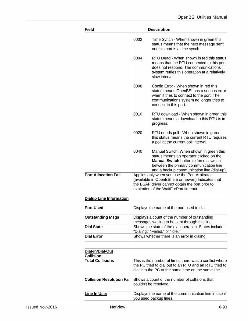
OpenBSI Utilities Manual
Issued Nov-2016 NetView 6-93
Field Description 0002 Time Synch - When shown in green this
status means that the next message sent out this port is a time synch.
0004 RTU Dead - When shown in red this status
means that the RTU connected to this port does not respond. The communications system retries this operation at a relatively slow interval.
0008 Config Error - When shown in red this
status means OpenBSI has a serious error when it tries to connect to the port. The communications system no longer tries to connect to this port.
0010 RTU download - When shown in green this
status means a download to this RTU is in progress.
0020 RTU needs poll - When shown in green
this status means the current RTU requires a poll at the current poll interval.
0040 Manual Switch. When shown in green this
status means an operator clicked on the Manual Switch button to force a switch between the primary communication line and a backup communication line (dial-up).
Port Allocation Fail Applies only when you use the Port Arbitrator (available in OpenBSI 5.5 or newer.) Indicates that the BSAP driver cannot obtain the port prior to expiration of the WaitForPort timeout.
Dialup Line Information Port Used
Displays the name of the port used to dial.
Outstanding Msgs Displays a count of the number of outstanding messages waiting to be sent through this line.
Dial State Shows the state of the dial operation. States include “Dialing,” “Failed,” or “Idle.”
Dial Error Shows whether there is an error in dialing.
Dial-in/Dial-Out Collision: Total Collisions
This is the number of times there was a conflict where the PC tried to dial out to an RTU and an RTU tried to dial into the PC at the same time on the same line.
Collision Resolution Fail Shows a count of the number of collisions that couldn’t be resolved.
Line In Use:
Displays the name of the communication line in use if you used backup lines.

OpenBSI Utilities Manual
6-94 NetView Issued Nov-2016
Field Description Manual Switch
If you defined backup communication lines (see Appendix H), you can switch between the primary line and the backup line by clicking this button.
6.21.7 Using the RTU Details Display for an IP RTU:
Figure 6-82. RTU Details Display – IP RTU
The various fields in the RTU Details display are:
Field Description Packet Information Pkts Recv
Shows the number of packets received from this RTU at this OpenBSI workstation.
Pkts Sent Shows the number of packets transmitted from this OpenBSI workstation to this RTU.
SubPkts Recv Shows the current number of sub-packets this OpenBSI workstation received from this RTU.
SubPkts Sent Show the current number of sub-packets this OpenBSI workstation sent out to this RTU.
Inv Pkts Shows the number of invalid packets this OpenBSI workstation received from this RTU
Inv SubPkts
Shows the number of sub-packets this OpenBSI workstation received from this RTU that did not have a valid identifier.

OpenBSI Utilities Manual
Issued Nov-2016 NetView 6-95
Error Information Ack Discard
Shows the number of messages from this RTU discarded by the OpenBSI workstation because of multiple acknowledgment timeouts for the same message.
Ack Timeout Shows the current number of acknowledgment message time outs. These occur when the OpenBSI workstation sends a message to this RTU but the RTU does not answer with the corresponding acknowledgment within the required time.
Discard Purge Shows the number of messages from this RTU that the OpenBSI workstation discarded by a purge operation.
Discard Quota Shows the number of messages from this RTU that the OpenBSI workstation discarded because the quota has been exceeded. This should always be zero.
Discard Seq Shows the number of messages from this RTU that the OpenBSI workstation discarded due to receipt of an unexpected sequence number.
Out Of Order Shows the number of packets the OpenBSI workstation received from this RTU that arrived out of order.
Fail Overs Shows the number of fail-overs that have occurred between communication lines (primary and secondary) for this RTU.
Fail Over Fails Shows the number of fail over operations that have failed (other line was not available.)
Restart Seq Shows a count of the times the OpenBSI workstation restarted the connection to this RTU.
Send Error Shows the number of errors the OpenBSI workstation had attempting to send a packet to this RTU.
Status/Status Bits A hexadecimal number which is the sum of the IP Status Bits used to describe the RTU’s current status. 0001 Off Line - This port was not configured or the
RTU was turned “off-scan” with the equivalent of #NDARRAY. This bit displays in RED when ON.
0002 Time Synch - The next message sent out this
port to this RTU will be a time synch. This bit displays in GREEN when ON.
0008 Config Error - OpenBSI encountered a serious

OpenBSI Utilities Manual
6-96 NetView Issued Nov-2016
error while trying to connect to the RTU through this port. OpenBSI no longer tries to connect to this port. This bit displays in RED when ON.
0040 Needs NRT - This RTU needs an IP Node
Routing Table. This displays in GREEN when ON.
0080 Line 2 act - The secondary line index, if it
exists, is active. This bit displays in GREEN when ON.
Line In Use Displays the current IP line that is in use, "P" for primary and "S" for secondary. The active IP line displays in GREEN, below.
6.21.8 Using the Message Exchange Summary Display
Message exchanges serve as “mailboxes” for communication between specific programs within OpenBSI, and between OpenBSI programs and RTUs. Each program receives and sends messages through its specific message exchange. The message distribution system handles the transport of these messages to other mailboxes on the system. The Message Exchange Summary Display can help you troubleshoot problems with these various programs.
Figure 6-83. Message Exchange Summary Display
To call up the Message Exchange Summary Display click the “Mex Summary” file tab in the NetView Monitor.

OpenBSI Utilities Manual
Issued Nov-2016 NetView 6-97
A number along the left-hand side of the window identifies each message exchange. Use the scroll bar to bring additional message exchanges, which do not fit in the window, into view.
The Message Exchange Summary display presents the following information for each message exchange.
Field Description Process The name of the program using this message
exchange.
WaitCnt Shows the number of packets transmitted from this OpenBSI workstation to this RTU.
InputWait The number of messages waiting on the input queue for processing.
MsgSent The current count of messages sent by this message exchange.
MsgRcv The current count of messages received by this message exchange.
6.21.9 Resetting the Message Exchange Statistics:
To reset counts to “0” click Initialize.
Note: This operation clears statistics for all message exchanges on both the summary and details displays.
6.21.10 Getting More Detailed Information about a Message Exchange
To obtain more detailed information about a particular message exchange, click anywhere on its line in the Message Exchange Summary Display. See Using the Message Exchange Details Display.
6.21.11 Using the Message Exchange Details Display
To bring up more information about a single message exchange, click anywhere on the line for that message exchange in the Message Exchange Summary Display. This activates the Message Exchange Details Display.

OpenBSI Utilities Manual
6-98 NetView Issued Nov-2016
Figure 6-84. Message Exchange Details Display
Field Description Process Shows the name of the program using this message
exchange.
Flags / Flag Bits Flags represents the sum (in hexadecimal) of whichever Flag Bits listed in the right part of the display, are currently set ON for this message exchange. Bits which are ON display in GREEN.
Buffers Wait Msgs
Shows the number of buffers waiting to be processed by this message exchange.
Wait Pkts Displays the number of messages already sent that await responses.
Max Buf Shows the maximum number of response buffers reserved.
Reserved Shows the number of response messages expected by the current message exchange.
Message Information Msgs Sent
Displays the current total count of messages sent out by this message exchange.
Msgs Recv Displays the current total count of messages received by this message exchange.
Over Res Shows the number of times that a message send was rejected because the number of buffers required for all outstanding requests (including the current one) exceeded the value of Max Buf. If this is a “non-throttled” message exchange, this statistic is not kept, and OpenBSI sends the message anyway.

OpenBSI Utilities Manual
Issued Nov-2016 NetView 6-99
No Buffs Shows the count of times that OpenBSI suspended a program due to a buffer shortage in the system.
Wait Lock Shows the number of times that OpenBSI skipped timeout processing on this message exchange because the wait pkts queue was locked.
Wait Tmo Shows the number of pending responses for this message exchange that have timed out.
Buff Tmo Shows the number of buffers that have timed out.
Lcl Copy Displays the number of times OpenBSI copies the contents of a buffer to process local storage due to a shortage in the number of system buffers.
Next Timeout Displays the number of timeout intervals for the first buffer on the wait queue.
Last Timeout Shows the estimated timeout for the last buffer on the lists.
6.21.12 Buffer Usage Summary Display
Buffers are portions of memory set aside for a particular purpose - - holding communication messages. The Buffer Usage Summary display shows the status of buffers used by the OpenBSI messaging system. (Do not confuse this with buffers in an RTU, which is an entirely different subject.)
To call up the Buffer Usage Summary display, click the “Buffer Usage” file tab.

OpenBSI Utilities Manual
6-100 NetView Issued Nov-2016
Figure 6-85. Buffer Usage Summary Display
Field Description Buffers Free
Shows the number of free buffers in the system. If no buffers are free, you may have a buffer shortage at the PC. You may need to increase the number of buffers defined in your NETDEF files.
Min Shows the minimum number of free buffers since the system started.
Reserved Shows the number of buffers reserved (the number of response buffers the system waits to use).
Max Shows the maximum number of buffers in simultaneous use since the system started.
Wait Packets Reserved
Shows the current number of wait packets in use. (Each message OpenBSI sends, that waits for a response, requires a wait packet.)
Max Shows the largest number of wait packets allocated since the system started.
6.21.13 Resetting the Buffer Statistics:
To reset counts to “0” click Initialize.
Note: This operation clears statistics for all buffers on the Buffer Summary display

OpenBSI Utilities Manual
Issued Nov-2016 NetView 6-101
6.21.14 Other Ways to View Communication Statistics
Even without starting the Monitor, you can see many of the same statistics by clicking on an RTU or communication line icon. Of particular interest is the information NetView displays for communication lines.
If you click on a dial-up line icon, NetView displays the following.
Figure 6-86. Communications Line Statistics
Field Description Line Name Shows the name of the communication line, as
defined in NetView. You may see an additional parameter if you configured this communication line for use by the BSAP to IP Redirector utility; “Primary” indicates the redirector sends communication messages to the RTU’s primary IP address; “Secondary” indicates the redirector sends communication messages to the RTUs’ secondary IP address.
Outstanding Msgs Shows the number of outgoing communication messages waiting for transmission through this communication line.
Dial-In Statistics Broadcast Msg Tmo
When an RTU dials in, OpenBSI sends a broadcast message asking for the RTU’s identity, i.e. a ‘Who are you?’ message. If OpenBSI does not receive a response it declares a timeout. This is a count of the number of such timeouts that have occurred.
Comm Failure Shows the number of RTU dial-in failures on this line.
Dial Info Dial
Shows the current state of dialing. This could be “Idle”, “Dialing” or “Failed”.
Dial Error If dialing fails, this is the error message about the failure.
RTU Shows the name of the RTU on this dial connection, and the dial string.

OpenBSI Utilities Manual
6-102 NetView Issued Nov-2016
6.22 RTU Communication Status Checking
Normally, you use the Monitor windows, or the Remote Communication Statistics Tool to check on the health of OpenBSI communications. NetView, however, allows you to configure a simple graphical representation of communication health that alerts you of the loss of communications with a particular RTU.
RTU communication status checking shows the on-line / off-line status of communications with RTUs in the NetView tree. If communications with a particular RTU go off-line, the RTU icon appears “crossed out” with a red “X” through it. By default, only one RTU appears crossed out per minute therefore there may be a delay before OpenBSI marks all off-line RTUs off-line.
Figure 6-87. RTU Communications Check
Notes:
Any changes you make to the properties of the RTU erase the “X” from the icon until the next communication check occurs. For example, if you right-click on the RTU icon and choose Properties from the pop-up menu, the “X” disappears until the next comm. status check. Do not mistake this for a restoration of communications to the RTU.
If an RTU is on a dial-up line, OpenBSI shows it as off-line anytime the dial connection is NOT active.
Only enable this feature if the RTUs reside on a relatively high speed network.
6.22.1 Activating / De-activating RTU Communication Status Checking
To activate RTU communication status checking, click on the NHP name, then choose NHP > Rtu Comm Check.
CW2 is off-line, as indicated by the read “X” through its icon.

OpenBSI Utilities Manual
Issued Nov-2016 NetView 6-103
Figure 6-88. Activating RTU Communications Check
The RTU Comm Check dialog box opens. To activate RTU communication checking, select the Enabled button.
Because of the overhead required to perform the communication check, OpenBSI only checks one RTU every 60 seconds, therefore, depending upon the number of RTUs in your network(s), it may take a long time for the OpenBSI workstation to check communications with all of them. To increase the speed at which the checking occurs, you can set a smaller value for the Time Interval between RTUs, however, remember that this may negatively affect system performance if you make the value too small.
To do a one-time quick check of communications with all RTUs, click the Quick Check button.
Click OK to exit the dialog box, and start the RTU communication status checking.
To turn OFF the RTU communication status checking, call up the RTU Comm Check dialog box again, and click the Disabled button, then click OK.
6.23 Searching For A Particular RTU in A Large Network
If you have a large network, containing hundreds of different RTUs, it may be inconvenient for you to scroll through the NetView tree to locate a particular RTU. To find the RTU, click the NHP icon, then choose NHP>Locate Rtu.
To perform a one-time check of communication with all RTUs, click here.
Click “Enabled” to activate RTU communication checking.

OpenBSI Utilities Manual
6-104 NetView Issued Nov-2016
The Select New Node dialog box opens. Enter the RTU’s name (or use the scroll bar to select it) and click OK. NetView then displays the portion of the network tree which includes the selected RTU.
6.24 Starting Other Programs From Within NetView
Once you establish communications with a particular RTU, you can start other programs for use with that RTU if you right-click on the RTU icon, and choose “RTU” from the pop-up menu, and then choose the action you want to perform.
Figure 6-89. Starting Other Programs in NetView
Table 6-1 describes the choices. Note: The available options vary depending upon the type of RTU.
Table 6-1. Programs You Can Start in NetView
Menu Item Utility Description
Change Local Address / Group Number
Choose “Change Local Address/Group Number” to change the local address or EBSAP group number of the attached 3530 TeleFlow / TeleRTU or ControlWave. Select the new address from the Select New Local Address list box or the new group number from the Select New Group Number list box and click on the associated Change button. See Figure Figure 6-89 Notes: This option only applies to 3530-series devices, and

OpenBSI Utilities Manual
Issued Nov-2016 NetView 6-105
Menu Item Utility Description ControlWave devices with 04.60 or newer firmware and actually changes the address within the device, not just in NetView.
Although this operation can change the group number, it does not change the RTU’s location in the network hierarchy. You must manually drag the icon for the controller under the correct Virtual Node.
Figure 6-90. Changing the Local Address / Group Number
Download This starts the Downloader. (See Chapter 7 for details.)
Signal Extractor This activates the Signal Extractor. (See Chapter 12 for details.)
DataView This starts DataView. (See Chapter 8 for details.)
Communication Statistics
This starts the Remote Communication Statistics Tool. (See Chapter 9 for details.)
Webpage Access This activates Microsoft® Internet Explorer and opens the startup web page associated with this controller.
To change the address or group number, select the new address or group number from the list box, then click the appropriate Change button.

OpenBSI Utilities Manual
6-106 NetView Issued Nov-2016
RTU Configuration Parameters
This starts the Flash Configuration Utility so you can set configuration parameters in the RTU. (See Assigning IP Addresses and Cold Download Parameters for the Attached RTU (Configure Mode) in Chapter 5 for details.
WinUOI This calls up the legacy Windows™ UOI/TMS/Smartkit shell. For information on this, see the addendum to the UOI Configuration Manual (document# D5074). Note: Not applicable for ControlWave users.
Workbench This activates the ACCOL Workbench program. (See the ACCOL Workbench User Manual (document# D4051) for details.) Note: Not applicable for ControlWave users.
ControlWave Designer
This activates the ControlWave Designer tool so you can build your IEC 61131 control strategy program(s). For information on ControlWave Designer, see Getting Started with ControlWave Designer (document# D5085), as well as the on-line help in ControlWave Designer.
ControlView This starts up the ControlView File Viewer utility.
Clear History Choose this to delete historical data from a ControlWave controller. See Deleting Archive Files and/or Audit Records from a ControlWave-series Controller later in this chapter for more information.
6.25 Documenting Your Network Configuration
If desired, you can save details of your network configuration in an ASCII text file. To generate this file, click, from the menu bar, on File>Document. NetView stores the resulting file in a default directory used to store your NETDEF files, and the file will have the same file basename as the NETDEF file, with a file extension of .DOC.
The illustration, below, shows portions of a sample file:
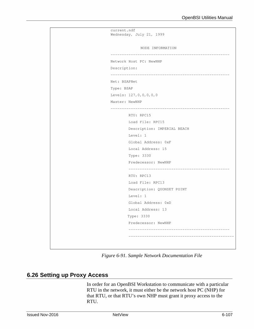
OpenBSI Utilities Manual
Issued Nov-2016 NetView 6-107
Figure 6-91. Sample Network Documentation File
6.26 Setting up Proxy Access
In order for an OpenBSI Workstation to communicate with a particular RTU in the network, it must either be the network host PC (NHP) for that RTU, or that RTU’s own NHP must grant it proxy access to the RTU.
current.ndf Wednesday, July 21, 1999
NODE INFORMATION
-----------------------------------------------------
Network Host PC: NewNHP
Description:
-----------------------------------------------------
Net: BSAPNet
Type: BSAP
Levels: 127,0,0,0,0,0
Master: NewNHP
-----------------------------------------------------
RTU: RPC15
Load File: RPC15
Description: IMPERIAL BEACH
Level: 1
Global Address: 0xF
Local Address: 15
Type: 3330
Predecessor: NewNHP
---------------------------------------------
RTU: RPC13
Load File: RPC13
Description: QUONSET POINT
Level: 1
Global Address: 0xD
Local Address: 13
Type: 3330
Predecessor: NewNHP
---------------------------------------------
-----------------------------------------------

OpenBSI Utilities Manual
6-108 NetView Issued Nov-2016
There are two types of proxy access: Proxy access and proxy direct access.
Proxy access means that the workstation communicates with RTUs by sending messages through the NHP for that RTU.
Proxy direct access means that the workstation can communicate directly with the RTUs of another NHP.
Either type of access allows the workstation to communicate with the proxy RTUs, to call up data from them in DataView, etc.
6.26.1 Steps for Setting up Proxy Access
1. If an NHP has RTUs for which you want to grant proxy access, create and export a proxy (.PXY) file for that NHP. This proxy file contains the IP addresses of the NHP, and the names of that NHP's RTUs for which you want to grant proxy access. See Creating and Exporting A Proxy File.
2. Import the proxy file (.PXY) created in Step 1 at any workstation which needs proxy access. See Importing A Proxy File.
Note: Any workstation that requests proxy access does not receive alarm/RBE reports from the proxy RTUs, even if the workstation is configured as an alarm/RBE destination at the proxy RTU's NHP.
6.26.2 Steps for Setting up Proxy Direct Access (IP RTU's ONLY)
1. First Set up proxy access as described above under Steps for Setting up Proxy Access.
2. For any workstation which needs proxy direct access, specify that it wants proxy direct access during its NHP configuration. You do this in the IP Parameters dialog box in the System Wizard, by answering Yes to the question "Would you like to access Proxy RTUs directly?" (If you didn’t do that originally, just set PROXY_DIRECT=TRUE in the [CONSTANTS] section of NDF file at the NHP for this RTU.)
3. For any IP RTU which this workstation will access directly, specify Yes to the question “Do you want this RTU to be accessed directly from Remote PCs?” in the RTU Wizard.
4. Define an IP communication line at the workstation which can handle the range of IP addresses for the RTUs that it will communicate with using proxy direct access.

OpenBSI Utilities Manual
Issued Nov-2016 NetView 6-109
6.26.3 Creating and Exporting a Proxy File
To create and export a proxy file, go to the workstation which serves as an NHP for the RTUs which you want to make available for proxy access. Right click on the NHP icon in NetView, and choose NHP>Proxy Export to open the RTU Proxy Export dialog box.
The left side of the RTU Proxy Export dialog box shows a list of all RTUs that belong to the current NHP which other workstations that request proxy access cannot currently communicate with. The right hand side shows a list of all RTUs that belong to the current NHP which other workstations that request proxy access can communicate with.
Figure 6-92. RTU Proxy Export dialog box
To add a single RTU to the list of proxy RTUs (which means that
other workstations can access those RTUs) click the RTU name on the left side of the dialog box, then click the > button. This removes the RTU name from the list on the left, and adds the name to the list on the right. (You can select multiple RTUs for proxy access if you
This button removes all RTUs from the list on the right.
This button removes the selected RTU from the list on the right.
Click here to call up the Save As dialog box, to export the proxy file.
This button adds all RTUs on the left to the list on the right.
This button adds the RTU selected on the left to the list of proxy RTUs on the right.
This side lists all RTUs which are accessible to workstations which request proxy access.
This side lists all RTUs belonging to the current NHP which are not accessible to workstations requiring proxy access.

OpenBSI Utilities Manual
6-110 NetView Issued Nov-2016
hold down the [Ctrl] key as you make your selections.) To add all RTUs of this NHP to the list of proxy RTUs, click the >> button.
To remove an RTU from the list of proxy RTUs (the list on the right
side of the dialog box), click on the RTU name, then click the < button. This adds the RTU to the list on the left. (You can select multiple RTUs for removal if you hold down the [Ctrl] key as you make your selections.)
To remove all RTUs from the list of proxy RTUs, click on the << button.
When the proxy list (list on the right) reflects the RTUs for which
you want to allow access by other workstations, click OK to open the Save As dialog box. Specify a name for the proxy (.PXY) file and click Save.
A typical proxy file appears below:
Figure 6-93. Proxy File
6.26.4 Importing a Proxy File
If a workstation needs access to RTUs that belong to another NHP, it must have a copy of that NHP's proxy file. To import the proxy file, copy it to a disk or use some other means to transfer it to the hard disk of the workstation that requires access. Right click on the NHP icon for the workstation which requires proxy access and choose NHP>Proxy Import from the pop up menus. Then specify the location (path and filename) of the proxy file you just copied to the hard disk, using the Open file dialog box.
6.27 Sending a Time Synch/NRT (TS/NRT) Message
When a controller recovers from a power failure, receives a newly downloaded control strategy file, or resets, it automatically requests a Node Routing Table (NRT) and Time Synchronization (TS) message from the controller (or workstation) immediately above it in the
[NHP]
NETWORK_TYPE=IP
NAME=NHP1
IP_PRIMARY=120.0.210.4
IP_SECONDARY=0.0.0.0
RTU_1=RPU3
RTU_2=RPU5

OpenBSI Utilities Manual
Issued Nov-2016 NetView 6-111
network. Once the controller receives its TS/NRT message, it sends it on to its slave nodes in the network, thereby propagating the message.
The Node Routing Table (NRT) describes the topology of the BSAP network, and allows a controller to know on which level it resides, and where it should send messages. The time synchronization (TS) portion of the message contains the current date and time from the OpenBSI workstation, allowing the time at the various controllers to remain synchronized.
Beginning with OpenBSI 4.02, you can force the OpenBSI Workstation to transmit a TS/NRT message to the BSAP network.
To transmit the TS/NRT message, right-click on the network icon in the NetView tree, and choose Send NRT / TimeSynch from the pop-up menu. NetView sends the message to all controllers in the network.
Note: If you have a special network configuration in which you might want to prevent processing of either the TS and/or NRT portion of the message on a particular port, you can configure most controller models ignore to those portion(s) of the message.
6.28 Deleting Archive Files and/or Audit Records
A ControlWave-series controller stores archive files of historical data, and audit records of significant system events. Normally, the Harvester, or some other program periodically collects this data for export to OpenEnterprise or a third-party package, and eventually new data overwrites the existing data.
If, however, you want to permanently delete audit or archive data residing in the ControlWave, you can use the Clear History function.
Note: The ControlWave-series controller must have 04.80 or newer firmware to use this function. This operation requires OpenBSI 5.7 or newer.
6.28.1 Deleting Historical Data
Caution If there should be a power failure to the ControlWave during the “Clear History” operation, files will not delete properly.
Caution If you want to save any Audit or Archive data, you must do this before you use the Clear History function.
We also recommend you save your current historical configuration to an FCP file prior to deleting audit or archive files, so that you can restore the structure (though not the data), if a failure occurs.
1. To delete historical data, right-click on the ControlWave in the NetView tree, and choose Clear History from the pop-up menu.

OpenBSI Utilities Manual
6-112 NetView Issued Nov-2016
2. Now, sign on to the ControlWave and provide a valid Username and Password combination. The Clear RTU History dialog box opens.
Figure 6-94. Deleting Historical Data
3. You have four possible choices on what to delete. See explanations
for the fields, below.
Field Description Clear Audit Records This choice deletes all Audit records residing in the
ControlWave.
Clear All Archive Files This choice deletes all Archive Files residing in the ControlWave.
Clear Single Archive File This choice deletes a single Archive File. When choosing this, use the list box to specify which Archive File you want to delete.
Clear All History (Audit and All Archives)
This choice deletes all Audit Records and all Archive Files.
4. After you make your choice, click OK to proceed with the deletions,
or Cancel to abort the operation. After you click OK NetView gives you a warning prompt and asks you to confirm that you want to perform the deletions.
Choose the type of historical data you want to delete, then click “Start.”

OpenBSI Utilities Manual
Issued Nov-2016 NetView 6-113
Caution Once you click OK to the deletion confirmation prompt, there is no way to reverse the deletion operation; the delete command removes the chosen files from the unit and the unit re-boots twice to accomplish the deletion operation.
Note: If you see the status message Not enough memory to complete parameter setting, it means the flash memory area is full and the deletion could not be completed because files are shifted during the deletion. If this occurs during the Clear All History, try clearing audit files first, then clear archives; if this doesn’t resolve the issue, use the Flash File Access tool to delete individual files and free up space. See the ControlWave Designer Programmer’s Handbook (D5125) for information on the Flash File Access tool.

This page is intentionally left blank
OpenBSI Utilities Manual
Issued Nov-2016 Downloader 7-1
Chapter 7 – Using the Downloaders
When you finish creating your control strategy file using ControlWave Designer or ACCOL Workbench, you have to transfer it to the actual controller; this process is called downloading.
In This Chapter
7.1 Starting the ACCOL Downloader ..................................................... 7-1 7.2 Downloading to a Single Network 3000 Node ................................. 7-3 7.3 Downloading to a Group of Network 3000 Nodes ........................... 7-3 7.4 Downloading to a ControlWave-series Node: .................................. 7-6
7.4.1 Before You Begin ................................................................. 7-6 7.4.2 Starting the ControlWave Downloader ................................. 7-9 7.4.3 Using the ControlWave Downloader .................................. 7-10 7.4.4 Creating Download Scripts for Batch Downloading of
ControlWave Controllers ................................................... 7-11 7.4.5 Running ControlWave Downloader from the Command Line7-13
The ControlWave Downloader transfers an IEC 61131 ControlWave project from the OpenBSI workstation to a running ControlWave series RTU.
The ACCOL Downloader transfers a linked ACCOL load file (*.ACL) from the OpenBSI workstation to a running Network 3000-series RTU.
Both downloaders support batch files that allow file downloads to multiple RTUs.
Warning Never attempt to download an untested program into an RTU currently running an industrial process or plant. Prior to downloading, isolate the RTU from the process and disconnect I/O. Failure to take such precautions could result in injury to persons or damage to property.
7.1 Starting the ACCOL Downloader
Notes:
Before attempting to download, you must establish communications with the controller using NetView, LocalView, or TechView.
If sufficient memory is available, you can run multiple copies of the downloader simultaneously.
There are two different ways to start the Downloader:
Method 1:
Click Start > Programs > OpenBSI Tools > ACCOL Tools > ACCOL Downloader. The ACCOL Downloader opens.

OpenBSI Utilities Manual
7-2 Downloader Issued Nov-2016
Figure 7-1. ACCOL Downloader
Method 2:
Right-click on the icon for the RTU you want to receive the download, then choose RTU>Download from the pop-up menus. The ACCOL Downloader opens. This method allows you to skip the Select New Node dialog box when you perform the download.
Figure 7-2. Starting the ACCOL Downloader
Either of these methods starts the ACCOL Downloader.
Number of retries
Number of bytes transmitted
Total number of bytes in ACL file
Message Area

OpenBSI Utilities Manual
Issued Nov-2016 Downloader 7-3
7.2 Downloading to a Single Network 3000 Node
To download to a single Network 3000 node, click on the icon, shown at left, or, from the menu bar, click File>Single Node.
This opens the Select New Node dialog box. Use the list box to select the Network 3000 node name, and click OK. (Note: The node name must exist in the currently released NETDEF files.)
Figure 7-3. Select New Node dialog box
A dialog box (Figure 7-4) with the node name in the title bar opens; type the password for the ACCOL load associated with this node in NetView, or select a different load using the Select File button first. As you type the password it appears as '*' characters on the screen. Click Begin to initiate a download of the file. A progress bar displays the percentage of the file which has been downloaded.
Figure 7-4. Download dialog box
While the download proceeds, you can open the Select New Node dialog box, again, and repeat the process to download another different Network 3000 node.
7.3 Downloading to a Group of Network 3000 Nodes
To download several ACCOL load files, use a text editor to create an ASCII file, with the extension (.RDL), in the directory containing your ACCOL loads. A sample RDL file is shown below.

OpenBSI Utilities Manual
7-4 Downloader Issued Nov-2016
Figure 7-5. Sample RDL File
Each line of the file must contain a single Network 3000 controller node name, a wait statement, or a comment.
Wait statements are optional commands that cause the Downloader to pause between downloads; a "!" character indicates a comment.
Note: Wait statements are useful if you want to first download to a master node, and then download to one of its slave nodes. The master needs time to “wake up” and start executing before it can accept download messages to one of its slave nodes.
Start the Downloader using Start > Programs > OpenBSI Tools > ACCOL Tools > ACCOL Downloader.
In the Downloader, click the icon, shown at left, or, from the menu bar, click File>Open List. Select the RDL file using the Open file dialog box, and click Open.
! Sample Remote Download (RDL) File
! Download nodes R1, R2, and R3
R1
R2
R3
! Pause 15 seconds before downloading R4
Wait 15
R4

OpenBSI Utilities Manual
Issued Nov-2016 Downloader 7-5
Figure 7-6. Selecting an RDL File
Once you click Open, a dialog box opens with the name of the RDL file in the title bar. To initiate the download, enter a password for the first load in the list, only, and click Begin. The Downloader attempts to download, in order, each load listed in the RDL file.
Figure 7-7. Entering a Password to Start the RDL Download

OpenBSI Utilities Manual
7-6 Downloader Issued Nov-2016
7.4 Downloading to a ControlWave-series Node:
Note: You can also download a project to a ControlWave directly from within ControlWave Designer. See the ControlWave Designer documentation for details.
7.4.1 Before You Begin
There are certain things you must do before you can download to a ControlWave-series controller.
You must save your project as a ControlWave project *.MWT file. You must generate a boot project file during compilation in
ControlWave Designer. To do this, you must check the Generate bootproject during compile box for your resource.
Figure 7-8. Generating a Bootproject During Compilation
Make sure this box is checked in ControlWave Designer when you compile/build your project.
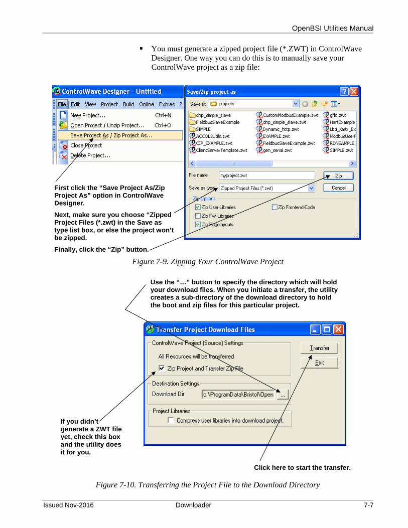
OpenBSI Utilities Manual
Issued Nov-2016 Downloader 7-7
You must generate a zipped project file (*.ZWT) in ControlWave Designer. One way you can do this is to manually save your ControlWave project as a zip file:
Figure 7-9. Zipping Your ControlWave Project
Figure 7-10. Transferring the Project File to the Download Directory
First click the “Save Project As/Zip Project As” option in ControlWave Designer.
Next, make sure you choose “Zipped Project Files (*.zwt) in the Save as type list box, or else the project won’t be zipped.
Finally, click the “Zip” button.
Use the “…” button to specify the directory which will hold your download files. When you initiate a transfer, the utility creates a sub-directory of the download directory to hold the boot and zip files for this particular project.
Click here to start the transfer.
If you didn’t generate a ZWT file yet, check this box and the utility does it for you.

OpenBSI Utilities Manual
7-8 Downloader Issued Nov-2016
You must transfer the bootfile and zip file for this project to a sub-directory of whichever directory you want to use for downloads. You can accomplish this if you click Build > Transfer Download Files in ControlWave Designer. In this utility, you must specify the download directory in the Download dir field. (See Figure 7-10.)
Note: Beginning with OpenBSI 5.8 Service Pack 1, if you use multiple configurations / resources in your project, OpenBSI can embed those in the PRO file name to differentiate between different PRO files from the same project. To do this, select the Add 1131 Configuration name… option in the Applications page of the Advanced Configuration utility. See Appendix E for more information on this option.
If you check Zip Project and Transfer Zip File (default), the system zips the current project automatically, in preparation for the transfer. If you select the Compress user libraries into download project option, the system zips the user libraries and includes them in the zip project.
Note: Zip Project and Transfer Zip overwrites any pre-existing zip file for this project. To prevent this, you can disable the option, however, if you do, you must have a previously created zip available for transfer.
When you finish making selections, click Transfer and the file transfer begins.
If your ControlWave-series node includes a key operated RUN / REMOTE/ LOCAL switch, you must turn the switch to either the REMOTE or LOCAL position, depending upon how the PC connects to the ControlWave. Downloading CANNOT occur with the switch in the RUN position.

OpenBSI Utilities Manual
Issued Nov-2016 Downloader 7-9
7.4.2 Starting the ControlWave Downloader
There are two methods for starting the ControlWave Downloader:
Method 1:
Click Start > Programs > OpenBSI Tools > ControlWave Tools > ControlWave Downloader. The Select New Node dialog box opens.
Figure 7-11. Select New Node Dialog Box
Use the list box to select the node which you want to download to; then click OK, and the Downloader opens.
Method 2:
The second method is to right-click on the icon for the controller you want to download, in the NetView tree, and choose RTU>Download from the pop-up menu.
Figure 7-12. Calling Up the Downloader

OpenBSI Utilities Manual
7-10 Downloader Issued Nov-2016
7.4.3 Using the ControlWave Downloader
When the ControlWave Downloader dialog box opens, complete the fields as described, below:
Figure 7-13. ControlWave Downloader
When the fields are completed, click Begin to start the download. The fields/buttons in this dialog box are:
Field Description
Node This displays the node name (as it appears in the NetView tree) for this ControlWave-series controller.
Username, Password Enter a valid username/password combination for this ControlWave-series controller.
Project Path Enter the path of the project that the Downloader will download to this controller, or use the Browse Bootfile button to locate it. (The path must be a sub-directory of whichever directory you specified for downloads (Download Dir) in the Transfer Download Files dialog box, Figure 7-10) The project files consist of the .PRO boot file, generated when you compile your ControlWave project, and the zip file (*.zwt) containing the project source. Note: If your project includes multiple resources, each one has a different path, and you must choose the
Click here to start the download. Enter the proper username and password for this controller.
When downloading a project, click “Warm Boot” to perform a warm download (project is started from the beginning using values saved as RETAIN – if project hasn’t changed to a degree that those values don’t apply). If you de-select “Warm Boot” a cold download occurs (project is started from the beginning using initial values.
Shows the progress of the download.
Check this to allow the ZWT file to download.
Check this box to download user files (.HTML, etc.) which the ControlView utility can retrieve later.
Use this browse button to choose the sub-directory containing your bootfile.pro and .zwt file.
RTU node name (as it appears in the NetView tree)
Use this browse button to choose the sub-directory containing user files. You can use the ControlView utility to retrieve these.

OpenBSI Utilities Manual
Issued Nov-2016 Downloader 7-11
appropriate one. Note: Beginning with OpenBSI 5.8 Service Pack 1, if your project includes multiple configurations / resources, depending on application settings, your PRO file name may include the configuration / resource name to help differentiate between multiple PRO files for the same project.
User Files Path Enter the path of the folder containing files you want to download to the user files area of the ControlWave, or use the Browse Path button to locate it. (See Download User Files, below).
Begin Click here to start the download.
Cancel Click here to exit down the 1131 Downloader.
Warm Boot When you don’t select this check box, all variables initialize as part of the download, and the project restarts. When you choose Warm Boot, any variables configured as RETAIN do not re-initialize as part of the download, however, all other variables initialize, and the project restarts from the beginning of its cycle.
ZipFile When you select this option, the download operation includes the zipped project file (*.ZWT).
Download User Files
The ControlWave can store user files (*.ZIP, *.HTML, etc.) in flash memory, for later retrieval using the ControlView utility. You must place the user files you want to download to the ControlWave in the folder identified by the User Files Path field. Note: This feature was added in OpenBSI 5.3 Service Pack 2.
7.4.4 Creating Download Scripts for Batch Downloading of ControlWave Controllers
Optionally, you can create download scripts which allow you to download files to ControlWave controllers using a single command.
You create download scripts as ASCII text files, with the file extension of *.RDL, and store them in the Downloads sub-directory of your OpenBSI directory.
Each line of the download script, defines the downloading parameters for a single ControlWave controller. The syntax of a line of the download script is:
nodename,filetype,startup,includezip,source_path

OpenBSI Utilities Manual
7-12 Downloader Issued Nov-2016
where:
nodename is the name of the ControlWave controller you want to download. This name must match the name you define in NetView. (This is the only required field.)
filetype specifies the kind of file you want to download. filetype must be either:
P Download a ControlWave project (default)
F Download a user file (used with ControlView)
startup specifies whether the system should perform a warm boot upon completion of the download. startup must be either:
Y Perform a warm boot (default)
N Do not perform a warm boot
includezip specifies whether or not the Downloader should also download the zipped ControlWave project (*.ZWT). includezip must be either:
Y Include *.ZWT with the download
N Do not include *.ZWT with the download (default).
path specifies the source folder containing the file you want to download. If you download a project, this must be the directory containing bootfile.pro. If you download user files for use with ControlView, this must be the folder containing those files. If the folder name contains spaces, you must surround it with quotation marks “ “. If you enter nothing here, the Downloader uses OpenBSI Application Parameter defaults.
Example RDL File:
RPC1,P,Y,Y,C:\”ProgramData”\Bristol\OpenBSI\rpc1
RPC2,P,Y,Y,C:\”ProgramData”\Bristol\OpenBSI\rpc2
RPC3,P,Y,Y,C:\”ProgramData”\Bristol\OpenBSI\rpc3
RPC4,P,Y,Y,C:\”ProgramData”\Bristol\OpenBSI\rpc4
Starting the Download Script
To start the download script you create, click on File > Open Script within the ControlWave Downloader, then choose the RDL file that contains the download script.

OpenBSI Utilities Manual
Issued Nov-2016 Downloader 7-13
You can also run download scripts from the command line prompt according to the following syntax:
dl1131 script_name username password
where:
script_name is the name of the RDL file (omitting the RDL extension)
username
password is a valid username/password combination for the first RTU in the script. The named user must have privileges sufficient to download.
For example, to run the download script myloads.RDL where the first RTU in the RDL file has a username/password combination of THOMAS BOB276, type the following:
dl1131 myloads THOMAS BOB276
7.4.5 Running the ControlWave Downloader from the Command Line
Optionally, you can start ControlWave Downloader from the DOS command prompt. Follow the syntax rules below; optional switches appear in brackets “[ ].” The command for this is:
dl1131 node [file] [username password]
where:
node is the RTU node name as defined in the NETDEF files. If no file is specified, the Downloader uses the file specified in the RTU Properties in NetView.
File is the basename of the ControlWave project. You can omit the .PRO or .MWT extension. When you specify a file, you override any filename specified in the RTU Properties in NetView. If the filename includes spaces, you must surround it with quotation marks “ “.
username
password
is a valid username/password combination for this RTU. The user you specify must have sufficient privileges to perform the download. If you omit this, you must have signed on previously or used automatic sign-on.

This page is intentionally left blank

OpenBSI Utilities Manual
Issued Nov-2016 DataView 8-1
Chapter 8 – Using DataView
DataView allows you to collect several types of data from a Network 3000-series or ControlWave series controller, including signal data, signal lists, archive data, analog data array values, and audit trail alarm/event information. In addition, it allows you to search for signals based on various criteria, and also allows you to send recipes (lists of signal values) to the controller.
In This Chapter
8.1 Starting DataView ............................................................................ 8-2 8.2 Using the Tool Bar within DataView ................................................ 8-3 8.3 Using the Select New Node Dialog Box, Signing on to a Node ...... 8-3
8.3.1 Using the Select New Node Dialog Box .............................. 8-4 8.3.2 Using the Sign On Dialog Box .............................................. 8-4 8.3.3 Configuring Automatic DataView Sign-On ........................... 8-5
8.4 Printing the Entries in the Current DataView Window ..................... 8-6 8.5 Exporting Data Entries to the Windows Clipboard ....................... 8-6 8.6 Conducting a Signal Search ............................................................ 8-7
8.6.1 Starting the Signal Search .................................................... 8-7 8.6.2 Saving Search Criteria ....................................................... 8-13 8.6.3 Retrieving Search Criteria .................................................. 8-13 8.6.4 Altering Search Criteria ...................................................... 8-13
8.7 Viewing Entries in a Signal Window .............................................. 8-14 8.7.1 Changing Signal Values in the Signal Window .................. 8-15 8.7.2 Changing Signal Inhibit/Enable Bits in the Signal Window 8-16 8.7.3 Changing the Floating Point Format of Data in the Signal
Window ............................................................................. 8-16 8.8 Displaying a Remote Signal List .................................................... 8-17
8.8.1 Selecting a Different Remote Signal List ............................ 8-17 8.8.2 Changing Remote List Signal Values, Altering
Inhibit/Enable Bits ............................................................. 8-18 8.9 Creating and Using DataView Lists ............................................... 8-18
8.9.1 Creating a DataView List .................................................... 8-18 8.9.2 Collecting Live Data into the DataView List ....................... 8-19 8.9.3 Saving the DataView List ................................................... 8-19 8.9.4 Viewing a Previously Saved DataView List ........................ 8-19
8.10 Creating and Using Recipes .......................................................... 8-19 8.10.1 Creating a Recipe ............................................................... 8-20 8.10.2 Saving the Recipe .............................................................. 8-20 8.10.3 To View/Modify an Existing Recipe File ............................. 8-21 8.10.4 To Update Signals in the Controller with the Recipe
Values ............................................................................... 8-21 8.10.5 To Read the Current Signal Values From the Controller Into
the Recipe Window ........................................................... 8-21 8.10.6 To Cancel Unsaved Modifications to the Recipe Values ... 8-21 8.10.7 Changing the Floating Point Format of Data in the Recipe
Window ............................................................................. 8-21 8.11 Viewing Data for a Single Signal ................................................... 8-22
8.11.1 Acknowledging an Alarm .................................................... 8-23 8.12 Viewing Data Arrays ...................................................................... 8-23
8.12.1 Changing Values in the Data Array .................................... 8-24 8.12.2 Toggling the Time/Value Format ........................................ 8-25 8.12.3 Keeping Column 1 Visible While Scrolling Through
the Array ........................................................................... 8-25

OpenBSI Utilities Manual
8-2 DataView Issued Nov-2016
8.12.4 Calling Up a Different Data Array ....................................... 8-25 8.12.5 Changing the Floating Point Format .................................. 8-25
8.13 Viewing Audit Trail Records .......................................................... 8-26 8.14 Viewing Archive Data Files ............................................................ 8-28
8.14.1 Keeping Column 1 Visible While Scrolling Through the Archive File ....................................................................... 8-29
8.14.2 Calling Up a Different Archive File ..................................... 8-29 8.14.3 Changing the Floating Point Format .................................. 8-29 8.14.4 Restrictions on Archive File Size ........................................ 8-29
8.1 Starting DataView
Note: Before starting DataView, you must establish communications with the controller using NetView, LocalView, or TechView.
There are two different ways to start DataView.
Method 1:
Click Start > Programs > OpenBSI Tools > Common Tools > DataView. DataView starts.
Figure 8-1. DataView
Method 2:
Right-click on the icon for the RTU you want to receive the view data from, then choose RTU>DataView from the pop-up menus. DataView opens.

OpenBSI Utilities Manual
Issued Nov-2016 DataView 8-3
Figure 8-2. Starting DataView
Either of these methods starts the ACCOL Downloader.
8.2 Using the Tool Bar within DataView
Notes:
You can run multiple DataView functions simultaneously in separate windows, if sufficient memory is available.
If sufficient memory is available, you can run multiple copies of DataView simultaneously.
The DataView window includes a tool bar which provides you easy access to DataView's features and functions, and serves as an alternative to using the menu bar and pull down menus. If you position the mouse cursor over any tool bar icon you can see a label which identifies the icon's function. (Note: The number and function of active icons in the tool bar varies depending upon which DataView feature currently runs in the window.) A single click on the icon activates its feature. See the pages which follow for a description of the various DataView features.
8.3 Using the Select New Node Dialog Box, Signing on to a Node
If you did not configure Automatic Sign-On, or if you have not previously signed on to a particular node, you must sign on. To do this, click the “Sign On To Remote RTU” tool bar icon, shown above, or click Security>Sign On from the menu bar. In instances where you previously signed on to a node, DataView assumes a default choice of the last node you selected, and the Sign On dialog box opens; otherwise the Select New Node dialog box opens.

OpenBSI Utilities Manual
8-4 DataView Issued Nov-2016
Using the Select New Node Dialog Box
Choose the name of the desired node from the list box, and click OK.
Figure 8-3. Select New Node dialog box
Notes:
In order for you to select a node, it must exist in the currently released NETDEF files. The Sign On dialog box now opens, with the node name in the title bar.
The Select New Node dialog box, and the Sign On dialog box appear throughout the OpenBSI Utilities, whenever you attempt to access a new node.
Using the Sign On Dialog Box
When the Sign On dialog box opens, type either the password for the node, or the user name and password combination for the node, depending upon which security scheme you use. When finished, click OK.
Figure 8-4. Sign On dialog box
(You can change the security scheme used by selecting / de-selecting the Username/Password Scheme option.) When you sign on successfully to a Network 3000 RTU, you have access to all DataView features and functions, as well as ACCOL structures in the Network 3000 RTU which share a security level less than or equal to the level for your password. When you sign on successfully to a ControlWave RTU, you have access to whichever privileges are available for your username.
If you choose the wrong node, click New Node to return to the Select New Node dialog box, described above.

OpenBSI Utilities Manual
Issued Nov-2016 DataView 8-5
Note: If you communicate from an OpenBSI Workstation to a ControlWave controller using PPP (Point-to-Point Protocol), the password you use to establish communications using PPP requires a minimum of 8 characters; however, DataView in OpenBSI Version 5.8 and earlier only supports passwords of 6 characters or less. In this situation, the controller must have a user defined with a password for PPP, and then a second user with a shorter password to support DataView. You must establish PPP communications first using the longer password, then log on as the second user using the shorter password supported by DataView. Two alternatives to this solution are to use OpenBSI 5.8 Service Pack 1 (or newer) which supports passwords of up to 16 characters or to use Web_BSI data collection web pages, instead of DataView, since they support longer passwords and so would not require you to define a second user.
Configuring Automatic DataView Sign-On
You can configure DataView with an automatic sign-on capability. This capability is useful in applications where you must examine data from several different nodes, and it would be tedious to sign-on to each node individually. Automatic sign-on allows you to define a single common security code (password), or a user name/password combination for DataView.
For this feature to work, you must configure the same security code or user name/password combination within each and every RTU you want DataView to access.
Figure 8-5. Set Default Password dialog box – Password Only
Figure 8-6. Set Default Password dialog box – Username and Password
To configure the automatic sign-on capability from the menu bar, click Security>Default Security. The Set Default Password dialog box opens. Enter either a default user name/password combination, or simply a password, depending upon the appearance of the dialog box. Click OK to save the defaults.

OpenBSI Utilities Manual
8-6 DataView Issued Nov-2016
Once configured, when you sign-on to DataView you only need to select a node; and call up the Sign On dialog box; DataView sends the password, or user name/password combination to the node automatically.
Note: The appearance of the Set Default Password dialog box varies depending upon whether you select Yes or No for the “Would you like to use the Username/Password scheme?” question in NetView’s System Wizard.. “Yes” causes DataView to use both the username and password, whereas “No” cause DataView to only use the password.
8.4 Printing the Entries in the Current DataView Window
You can print the textual data displayed in the various types of DataView Windows on a printer.
Notes:
Before attempting to print, you must configure a printer and connect it to this workstation, either directly, or through a network. To access the Windows Print Setup dialog box, click File > Print Setup.
The types of DataView windows which hold printable data include Signal windows (which are used to display Signal Searches, DataView Lists, or Remote Lists) as well as other types of windows such as Audit Trail windows, Archive windows, and Array windows. All of these types of windows will be discussed later in this manual.
To preview the data you want to print, click File>Print Preview from the menu bar.
To print the entries (data) in the current DataView window, click the printer icon, shown above, or click File>Print. The Windows Print dialog box opens. See your Windows documentation for further information.
8.5 Exporting Data Entries to the Windows Clipboard
As an alternative to sending data to the printer, described above, you can copy DataView window entries as text to the Windows Clipboard. From the Clipboard, you can export the data to other Windows applications such as spreadsheets or word processors. DataView formats its entries specifically for use in Microsoft Excel.
To copy entries in the current DataView window to the Windows Clipboard, click File>Copy to Clipboard.
See your Windows documentation for more information on using the Clipboard.

OpenBSI Utilities Manual
Issued Nov-2016 DataView 8-7
8.6 Conducting a Signal Search
A signal search allows you to search for all signals (variables) which share one or more common characteristics. For example, you can define the search criteria to be all signals which share the same signal extension and are control-inhibited. Or you could search for all signals currently in the high-high alarm state. The following is a list of valid signal search criteria:
Signal base name, extension, or attribute (Network 3000 or ControlWave configured to use ACCOL names)
Variable/function block instance name (ControlWave only) String Search (ControlWave only) Current alarm state (logical alarm, high, high-high, low, low-low) Inhibit/enable bit status (alarm inhibit/enable, control inhibit/enable,
manual inhibit/enable) Questionable data bit status
Starting the Signal Search
To start a Signal Search, click on the Signal Search tool bar icon (shown at left), or click File > New, and then click Signal Search in the New list box. Either method opens the Signal Search Properties dialog box.
Use the Node list box to identify the RTU you want to search. Then use the other fields to specify the parameters of your search.
Notes:
Some of the searches support wildcard characters. Wildcard characters allow you to search for items for which you don’t know the exact name, or for which there may be several possible matches. There are two wildcard characters supported, “*” and “?”
The * indicates that DataView should automatically consider any characters in the position where the * appears as valid matches for this search. For example, if you search for “COMP*,” items like “COMP4,” “COMPRESSOR” and “COMPORT” are all considered valid matches.
The ? indicates that DataView should accept the substitution of any one single character for the question mark as a valid match for this search. For example, if you search for “PUMP?RUN” then “PUMP1RUN,” “PUMP2RUN” or “PUMPNRUN” are all considered valid matches.

OpenBSI Utilities Manual
8-8 DataView Issued Nov-2016
Figure 8-7. Signal Search Properties dialog box
Instance/Variable Search Mode:
For ControlWave controllers you can search based on the POU Instance name(s), and/or the Variable name. You can use wildcards in either of these fields.
The same variable can have multiple instance names associated with it, for example, an instance for the program, followed by the instance for a function block, etc. A period “.” character follows each instance therefore an instance name is always to the left of the last period. DataView considers the portion to the right of the last period to be the variable name. The signal search can only find variables which you previously marked as “PDD.”
Field Description
Instance You can enter up to 32 characters in the Instance name portion. If you do NOT use wildcard characters, the instance name must match exactly to be considered a valid match. For global variables the POU instance name must be “@GV.” If you leave the Instance field blank, DataView considers any instance name to be valid, and it only uses the Variable field in the search.
Variable You can enter up to 32 characters in the Variable name portion. If you do NOT use wildcard characters, the variable name must match exactly to be considered a valid match. If you leave the Variable field blank, DataView only uses the Instance field in the search
Some Examples:
Choose the type of search you want to conduct.

OpenBSI Utilities Manual
Issued Nov-2016 DataView 8-9
@[email protected][email protected][email protected][email protected][email protected][email protected][email protected][email protected]_FLOWPROG1.TEMP_HIGHPROG1.TEMP_LOWPROG1.TEMP_CURRENT
instancename
instancename
variable name
variable name
variable name
multipleinstancenames
Let’s say you have a set of variables with the following names (Figure 8-8).
Figure 8-8. Sample Set of Variables
Table 8-1 lists some resulting matches for searches based on this set of variables:
Table 8-1. Sample Search Results – Instance / Variable
If you enter this in the
Instance field
And you enter this in the Variable field
DataView returns the following variables from the set of variables shown in Figure 8-8.
* STATION1* @GV.MYFB.STATION1_FLOW @GV.MYFB2.STATION1_FLOW
leave blank TEMP* PROG1.TEMP_HIGH PROG1.TEMP_LOW PROG1.TEMP_CURRENT
@GV.MYFB* STATION2* @GV.MYFB.STATION2_FLOW @GV.MYFB2.STATION2_FLOW
PROG TEMP* No matches; because no wildcard following ‘PROG’.
PROG* leave blank PROG1.TEMP_HIGH PROG1.TEMP_LOW PROG1.TEMP_CURRENT
@GV.MYFB2 leave blank @GV.MYFB2.STATION1_FLOW @GV.MYFB2.STATION2_FLOW @GV.MYFB2.STATION3_FLOW @GV.MYFB2.STATION4_FLOW
*.* STATION3* @GV.MYFB.STATION3_FLOW @GV.MYFB2.STATION3_FLOW

OpenBSI Utilities Manual
8-10 DataView Issued Nov-2016
If you enter this in the
Instance field
And you enter this in the Variable field
DataView returns the following variables from the set of variables shown in Figure 8-8.
* leave blank @GV.PRESSURE_READING @GV.MYFB.STATION1_FLOW @GV.MYFB.STATION2_FLOW @GV.MYFB.STATION3_FLOW @GV.MYFB.STATION4_FLOW @GV.MYFB2.STATION1_FLOW @GV.MYFB2.STATION2_FLOW @GV.MYFB2.STATION3_FLOW @GV.MYFB2.STATION4_FLOW PROG1.TEMP_HIGH PROG1.TEMP_LOW PROG1.TEMP_CURRENT
*.* leave blank @GV.MYFB.STATION1_FLOW @GV.MYFB.STATION2_FLOW @GV.MYFB.STATION3_FLOW @GV.MYFB.STATION4_FLOW @GV.MYFB2.STATION1_FLOW @GV.MYFB2.STATION2_FLOW @GV.MYFB2.STATION3_FLOW @GV.MYFB2.STATION4_FLOW
*.MYFB2 leave blank @GV.MYFB2.STATION1_FLOW @GV.MYFB2.STATION2_FLOW @GV.MYFB2.STATION3_FLOW @GV.MYFB2.STATION4_FLOW
leave blank or *
STATION?_FLOW @GV.MYFB.STATION1_FLOW @GV.MYFB.STATION2_FLOW @GV.MYFB.STATION3_FLOW @GV.MYFB.STATION4_FLOW @GV.MYFB2.STATION1_FLOW @GV.MYFB2.STATION2_FLOW @GV.MYFB2.STATION3_FLOW @GV.MYFB2.STATION4_FLOW
*.MYFB2* STATION2_FL?W @GV.MYFB2.STATION2_FLOW
PROG? leave blank PROG1.TEMP_HIGH PROG1.TEMP_LOW PROG1.TEMP_CURRENT
@GV.MYFB? leave blank @GV.MYFB.STATION1_FLOW @GV.MYFB.STATION2_FLOW @GV.MYFB.STATION3_FLOW @GV.MYFB.STATION4_FLOW @GV.MYFB2.STATION1_FLOW @GV.MYFB2.STATION2_FLOW @GV.MYFB2.STATION3_FLOW @GV.MYFB2.STATION4_FLOW

OpenBSI Utilities Manual
Issued Nov-2016 DataView 8-11
ControlWave Full String Search Mode:
For this search, you can enter a string that is in either the instance name or variable name.
The search string you enter can include wildcards to establish a pattern for DataView to match.
Table 8-2 shows some examples, using the same set of variables from Figure 8-8.
Table 8-2. Sample Search Results – String
If you enter this in the String field
DataView returns the following variables from the set of variables shown in Figure 8-8.
*STATION?_F*
@GV.MYFB.STATION1_FLOW @GV.MYFB.STATION2_FLOW @GV.MYFB.STATION3_FLOW @GV.MYFB.STATION4_FLOW @GV.MYFB2.STATION1_FLOW @GV.MYFB2.STATION2_FLOW @GV.MYFB2.STATION3_FLOW @GV.MYFB2.STATION4_FLOW
*MYFB?.STATION2*
@GV.MYFB.STATION2_FLOW @GV.MYFB2.STATION2_FLOW
*1* @GV.MYFB.STATION1_FLOW @GV.MYFB2.STATION1_FLOW PROG1.TEMP_HIGH PROG1.TEMP_LOW PROG1.TEMP_CURRENT
@GV.P* @GV.PRESSURE_READING
ACCOL Base, Extension, and Attribute Search Mode
For Network 3000 controllers, you can search based on a portion of the signal’s name. The Base, Extension and Attribute fields include list boxes which allow easy selection from the available base names, extensions, and attributes in a given ACCOL load.
OpenBSI Utilities Manual
8-12 DataView Issued Nov-2016
Notes:
Do not enter wildcard characters in this mode. You must search using the complete, Base, Extension, or Attribute,
not part of it. For example, to search for an attribute of “FLOW,” you must enter “FLOW,” not “FLO,” “FL,” or “F.”
Network 3000 User Note: DataView uses the ACO and ACL files on the PC hard disk to create the Node, Base, Extension, and Attribute lists. Because not all versions of the EGM 3530 TeleFlow include an ACCOL load, some TeleFlow users must type the Node, Base, Extension, or Attribute directly; there is no list to choose from. This situation also occurs if the ACO/ACL file base name has not been specified as the Node Load File Name in the currently released NETDEF files.
If DataView communicates with a ControlWave and you set the _USE_ACCOL_NAME system variable in your ControlWave project to TRUE, you can also use the Base, Extension and Attribute fields. To work properly in this case, though, the signal names you search for must fit the ACCOL II signal naming convention, i.e. no more than eight alpha-numeric characters for the base, no more than six for the extension, and no more than four for the attribute. In addition, characters such as the at sign “@” cannot be included. The underscore “_” may work if it’s at the end of the search parameter, but it will not work at the beginning of the search parameter.
Signal Search Notes for ControlWave Users
To see all variables in the project (both global and local variables marked as “PDD”) only specify the Node name when you start the search; leave all other fields blank. Because your signals must follow naming conventions carefully in this mode, we recommend that when you communicate with ControlWave that you use one of the other search modes, and leave _USE_ACCOL_NAME set at FALSE.
Notes about STRING variables
The standard IEC62591 STRING data type allows up to 80 characters. You can also create string variables using user-defined STRING data types of varying lengths. Be aware that in either case, there are restrictions on displaying strings in programs outside of ControlWave Designer:
ControlWave RTUs do not report strings that exceed 127 characters and behave as if the variable does not exist when data requests come in for that variable from software.
OpenBSI tools such as DataView can only display the first 64 characters of a ControlWave string variable.

OpenBSI Utilities Manual
Issued Nov-2016 DataView 8-13
In Alarm and Quality Bits
The In Alarm check boxes let you select signals which share the same alarm status.
The Quality Bits area list boxes allow you to select signals based on the inhibit/enable status for each alarm, control, or manual inhibit/enable bit. You can also select based on the Questionable data status.
Select the desired search criteria, and click OK to execute the search. A signal window opens to display all signals/variables which share the selected characteristics. See Viewing Entries in the Signal Window for information on using the entries in this window to change signal values, or to alter inhibit / enable bits. See Viewing Data for a Single Signal for information on viewing more detailed signal information. Note: The window can only display the first 5000 signals found..
Saving Search Criteria
Once the Signal Window opens you can save its associated signal search criteria in a file by clicking on the icon, shown at left, or you can click File>Save As. Enter a name for the search criteria file, with an extension of .SCH. You can save subsequent modifications to the SCH file if you click on the same icon, or click File>Save.
Retrieving Search Criteria
DataView lists the names of the last four files viewed (of all file types) in the File pull down menu. If the search criteria (.SCH) file you want to view appears in the menu, you can open the file by simply clicking on the file name. To call up any other search criteria (SCH) file, click the icon, shown at left, or click File>Open. Select the desired SCH file from the windows Open File dialog box, and click the Open button.
Altering Search Criteria
Once the Signal Window opens, you can change the search criteria by clicking on the Properties tool bar icon, shown at left, or by clicking on Format>Properties. The Signal Search dialog box re-opens to allow you to define new search criteria.

OpenBSI Utilities Manual
8-14 DataView Issued Nov-2016
8.7 Viewing Entries in a Signal Window
DataView displays Remote Signal Lists, DataView Lists, and Signal Searches in a signal window. You can view detailed signal information, change signal values, or alter the inhibit/enable bits by clicking on those fields for a particular entry in the signal window. Use the scroll bar to view any entries not currently visible on the screen. The figure below summarizes the elements in a signal window.
Figure 8- 9. Signal Window
File name for the signal search
Signal Name (click on to get more detailed info)
Inhibit/Enable status bits (click on them to change status) Units Text (or
ON/OFF text)
Number of pending writes to controller
Current operator security level
Number of entries collected
Error/Status Message area
(If value appears in red, signal is “in-alarm;” if “!” appears, alarm has not been acknowledged by the central computer (HMI/SCADA package)
Signal Value (click on the value to change it)

OpenBSI Utilities Manual
Issued Nov-2016 DataView 8-15
Notes:
For information on viewing detailed signal information, see Viewing Data for a Single Signal, later in this section.
For Remote Signal Lists, and Signal Searches, the number of entries which have been collected are displayed at the bottom of the window in the status bar. If this value appears with a cyan (light blue) background, then there are additional entries in the controller which have not yet been collected
Changing Signal Values in the Signal Window
Click on the signal value you want to change. The Change Signal Value dialog box opens to allow you to change the signal value, as well as the manual, control, and alarm inhibit/enable bits, and the questionable data bit.
Note To change a signal value, you must manually enable the signal (if it isn’t already).
Figure 8-10. Change Signal Value – Analog
If the signal you want to change is a logical signal, you can either use the list box to select the new state, or you can simply click on the Toggle push button.
Figure 8-11. Change Signal Value – Logical

OpenBSI Utilities Manual
8-16 DataView Issued Nov-2016
Note: The questionable data bit for logical signals can only be changed through this dialog box; there is no automatic questionable checking from the discrete I/O boards.
Changing Signal Inhibit/Enable Bits in the Signal Window
Click the inhibit/enable bit you would like to change. DataView prompts you to confirm that you want to change the inhibit/enable status. You can also change the inhibit/enable status using the Change Signal Value dialog box, above.
Figure 8-12. Change Inhibit/Enable Status
Changing the Floating Point Format of Data in the Signal Window
The Signal Window (and certain other types of windows) displays analog values according to a default floating point format. To alter this default format, click on the Change Floating Point Format tool bar icon (shown at left) or click Format Floating Point. The Change Floating Point Format dialog box opens. Use the Width list box to specify the total number of characters in the field (including the decimal point) used to display a floating point number.
Figure 8-13. Change Floating Point Format dialog box
Use the Precision list box to choose the number of places to the right of the decimal point which the window should display.
Use the Exponent list box to choose floating point format f, exponential notation e or choose g to have DataView choose the “best fit” format.
If you want the floating point format defined here to apply throughout the DataView windows, check the Apply Globally check box.

OpenBSI Utilities Manual
Issued Nov-2016 DataView 8-17
8.8 Displaying a Remote Signal List
The Signal Window (and certain other types of windows) displays analog values according to a default floating point format. To alter this default format, click on the Change Floating Point Format tool bar icon (shown at left) or click Format Floating Point. The Change Floating Point Format dialog box opens. Use the Width list box to specify the total number of characters in the field (including the decimal point) used to display a floating point number.
To view a signal list in the remote process controller, click the Remote List tool bar icon, shown at left or click File>New. Choose Remote List from the New list box.
Figure 8-14. Remote List Properties dialog box
You can use the List list box to see which signal lists exist in the controller, and then select a list from it, or you can just type the list number in the box; then click OK. A signal window opens containing the signal list entries.
Beginning with OpenBSI Version 5.8, if you check Display Descriptors, signal descriptive text, if it exists, appears in the signal window instead of the signal name.
Notes:
DataView cannot display more than 10,000 signals from a particular signal list. (5,000 for versions prior to OpenBSI 5.8 Service Pack 1.)
Beginning with OpenBSI 5.9 Service Pack 3, DataView can display lists numbered higher than 255.
Network 3000 Users: DataView uses the ACO/ACL files on the PC hard disk to create the list of available remote signal lists. Because not all versions of the EGM 3530 TeleFlow include an ACCOL load, some TeleFlow users must type the remote list number directly; there is no list to choose from. This situation also occurs if the ACO/ACL file base name has not been specified as the Node Load File Name in the currently released NETDEF files.
Selecting a Different Remote Signal List
Once the Signal Window opens, you can recall the Remote List Properties dialog box to call up a different list by clicking the Properties icon, shown at left, or by clicking Format>Properties.

OpenBSI Utilities Manual
8-18 DataView Issued Nov-2016
Changing Remote List Signal Values, Altering Inhibit/Enable Bits
See Section 8.7 for information on using the entries in this window to change signal values, or to alter inhibit/enable bits. See Viewing Data for a Single Signal (later in this manual) for information on viewing more detailed signal information.
8.9 Creating and Using DataView Lists
A DataView List is a file, stored on the PC, that contains the names of signals, from a single controller, from which you would like to collect data. You can open the DataView list file in DataView to collect and display data for the designated signals.
Figure 8-15. DataView List
Creating a DataView List
Click the DView List icon, shown above, or click File>New and then click DView List in the New list box; in either case, an empty DataView List signal window opens.
From the menu bar, click Edit>Insert, and the Signal Properties dialog box opens.
Figure 8-16. Remote List Properties dialog box
Enter a signal name in the Name field, and click OK; the dialog box inserts the signal on the currently highlighted line, and pushes down any entries that begin on that line. Repeat this step for each additional signal you want to include in the DataView List. Note: Be sure you include the proper punctuation for the signal/variable.
If you make a mistake on a particular line, click on the line you want to change, then click Edit>Modify; the Signal Properties dialog box re-opens, allowing you to edit the signal name.

OpenBSI Utilities Manual
Issued Nov-2016 DataView 8-19
If you want to delete a particular line, click the line you want to delete, and then click Edit>Delete. The system prompts you to confirm that you want to delete the line from the DataView List; click Yes and the system removes that signal from the DataView List.
Collecting Live Data into the DataView List
The system suspends collection of DataView List data while you create or modify the DataView List, or if certain error conditions exist. When you finish creating/editing the list, you can activate collection if you click View>Refresh.
Saving the DataView List
If this is a new DataView List, you must save it by clicking on the icon, shown at left, or by clicking File>Save As. Assign a name to the DataView List file using the Windows Save As dialog box. All DataView Lists have a file extension of (.DVL).
To save modifications to a previously saved DataView List, click on Save toolbar icon, shown above, or click File>Save.
Viewing a Previously Saved DataView List
The File pull down menu shows the names of the last four files viewed (of all file types). If the DataView List (.DVL) file you want to view appears in the menu, you can open the file simply by clicking on the file name. To view any other DataView List (.DVL file), click the Open File tool bar icon, shown above, or click File>Open. The Windows Open File dialog box opens. Select the DataView List file, and click the Open button. The selected DataView List displays on the screen. Assuming OpenBSI is already running, you can also open a DataView list by double-clicking on the DVL filename in Windows.
Note: DataView cannot display more than 100 signals from a DataView list.
See Section 8.7 for information on using the entries in this window to change signal values, or to alter inhibit/enable bits. See Viewing Data for a Single Signal (later in this manual) for information on viewing more detailed signal information.
8.10 Creating and Using Recipes
A recipe is a list of signals, together with signal values, which DataView stores in a file, on the PC. You call up the recipe file, within DataView, and you can send the signal values to the remote process controller, to update the current values of those signals in the controller. This provides a quick way to change the values of several signals in a running load at the same time.

OpenBSI Utilities Manual
8-20 DataView Issued Nov-2016
Creating a Recipe Click the Recipe icon, shown above, or click File>New, and select Recipe from the New list box. An empty recipe window opens.
Figure 8-17. Recipe Window
Click Edit>Insert and the Signal Properties dialog box opens. Enter a signal name in the Name field, and a value for the signal in the Value field, then click OK. DataView inserts the signal on the currently highlighted line, and pushes down any entries that begin on that line. Repeat this step for each additional signal you want to include in the Recipe.
Figure 8-18. Adding Signals to the Recipe
\\
Although DataView performs no verification with the remote load when you create the recipe, you should remember that if you enter a logical signal in the recipe, only two values are valid:1.0 for ON, 0.0 for OFF.
If you make a mistake on a particular line, click on the line you want to change, then click Edit>Modify; the Signal Properties dialog box opens, allowing you to edit the signal name and/or value.
If you want to delete a particular line, click on the line you want to delete, then click Edit>Delete. DataView prompts you to confirm that you want to delete the line from the Recipe; click Yes and DataView removes that signal from the Recipe.
Notes:
OpenBSI 5.8 Service Pack 1 supports recipes up to 10,000 lines. OpenBSI 5.6 through 5.8 supported recipes up to 5000 lines. OpenBSI 5.4 through 5.5 supported recipes up to 1000 lines; earlier
versions supported 500 lines.
Saving the Recipe
When the Recipe is complete, you must save it by clicking on the icon, shown at left, or click File>Save As. Assign a name to the Recipe file using the Windows Save As dialog box. All Recipes have a file extension of (.RCP). To save modifications to a previously saved Recipe, click the Save toolbar icon, shown above, or click File>Save.

OpenBSI Utilities Manual
Issued Nov-2016 DataView 8-21
To View/Modify an Existing Recipe File
The File pull down menu displays the names of the last four files viewed (of all file types). If the Recipe (.RCP) file you want to view appears in the menu, you can open the file by simply clicking on the file name. To view any other Recipe (.RCP) file, click the Open File tool bar icon, shown above, or click File>Open. Select the recipe file from the Open File dialog box, and the recipe displays on the screen in a recipe window. Assuming OpenBSI is already running, you can also open a Recipe if you double-click on the RCP filename in Windows.
You can make modifications to signal names in the recipe by clicking on the line you want to change, and choose Edit>Modify. You can then change the signal name and/or value using the Signal Properties dialog box. You can also change recipe values by overwriting the values with the current values in the controller (see To Read the Current Signal Values from the Controller into the Recipe Window).
To Update Signals in the Controller with the Recipe Values
Bring up the recipe to view (described above under To View/Modify an Existing Recipe File) and click Recipe>Write to RTU. The Select New Node dialog box opens. Select the node which you want to receive the new values and sign-on to that node; DataView writes the values to the corresponding signals in the node. Note: In order to update the signals, you must manually enable them.
To Read the Current Signal Values From the Controller Into the Recipe Window
Bring up the recipe to view (described above under To View/Modify an Existing Recipe File). Next, click on Recipe>Read from RTU. The Select New Node dialog box opens. Select the node which will provide the new values and sign-on to that node. DataView copies the values in the node, for the signals in the recipe, into the window.
To Cancel Unsaved Modifications to the Recipe Values
If you made changes to recipe values in the recipe window, but have not saved them, and you want to cancel the changes, and return to the previously saved recipe values, click Recipe>Reload. DataView restores the previously saved recipe values into the recipe window.
Changing the Floating Point Format of Data in the Recipe Window
You can change the floating point format in which DataView presents signal values. See the sub-section on floating point formats in the Viewing Entries in the Signal Window section.

OpenBSI Utilities Manual
8-22 DataView Issued Nov-2016
8.11 Viewing Data for a Single Signal
You can view detailed signal information by clicking on a signal name in any Signal Window you open using DataView's Signal Search, DataView List, or Remote List features. Alternatively you may also view detailed information on a single signal by clicking on the Signal Detail toolbar icon (shown above) or you can click File>New, and then select Signal Detail from the list box. The Signal Detail Properties dialog box opens.
Choose the RTU name from the Node list box, then enter the complete signal name i.e. base.extension.attribute and click OK.
Figure 8-19. Signal Detail Properties dialog box
Figure 8-20. Signal Detail Window
(RED indicates currently in alarm state)
Signal Value
Read Priority
Inhibit/Enable Bits
Alarm Limits
Alarm Deadbands
Current Alarm State: On = In Alarm Off = Not in Alarm
Alarm Report State: Blank = no report Mo = momentary alarm Mult = multiple alarms Single = one alarm
Ack Status: Acked = Acknowledged NotAck= Not acknowledged
Show / Hide alarm limits and deadbands
Alarm Priority: Critical Non-Critical Operator Guide Event
Write Priority
Alarm Acknowledge
MSD Address (Emerson use only)
Units Text
Node Name
Signal / Variable Name Descriptive Text

OpenBSI Utilities Manual
Issued Nov-2016 DataView 8-23
A Signal Detail window contains the signal name, base name descriptive text, inhibit/enable bit values, signal value, units text or ON/OFF text, read priority, write priority, and other data. The figure above shows the window for an analog alarm signal. If you want, you can change the signal's value, or alter the inhibit/enable bits by clicking on those fields, and entering the new data via a dialog box.
Acknowledging an Alarm
If the signal you view is an alarm signal in an alarm state, and this alarm has not been acknowledged (as indicated by an exclamation point “!” next to the signal's value) you can acknowledge the alarm if you click on the Ack Alarm button. A message box opens indicating the status of the acknowledgment operation.
8.12 Viewing Data Arrays
To view a Data Array in the controller, click on the Array tool bar icon (shown above) or click File>New, then select Array.
The Array Properties dialog box opens. Choose the node which contains the array using the Node list box. Specify the Array Type as either analog or logical.
Figure 8-21. Array Properties dialog box
Use the Array Num list box to determine which arrays exist in the controller. Select the array from the list box, or enter the array number in the box. If the array is large, and you want to begin viewing from some row other than 1, enter that row in the Starting Row field.
Click OK; and DataView displays the array.
Notes:
Some versions of the 3530 TeleFlow do not support data arrays, and use archive files exclusively.
If you cannot see a list of arrays using the Array Num list box, it means DataView does not have access to your control strategy file.
If this is a large array, a scroll bar appears to let you view portions which do not currently fit in the window.

OpenBSI Utilities Manual
8-24 DataView Issued Nov-2016
The lower right corner of the window displays the total number of array rows, total number of array columns, and the current operator security level.
Figure 8-22. Array Window
Changing Values in the Data Array
If this is a read-write array, you can alter data array values if you click on the array cell you want to change, and enter a new value using the Change Value dialog box.
Figure 8-23. Change Value dialog box
Number of rows
Number of columns
Current operator security level
Error / status messages

OpenBSI Utilities Manual
Issued Nov-2016 DataView 8-25
Toggling the Time/Value Format
Depending upon how you configure the data array, it may include Julian date/time stamps in the first column. To convert these time/date stamps to the numerical total used by the system to store the date and time, and vice versa, click Format> View First Column as Date/Time.
Keeping Column 1 Visible While Scrolling Through the Array
As you scroll through columns of the data array, the first column (which may contain date/time stamps) may disappear from the window as higher numbered columns come into the window. To prevent this, click the icon, shown above, or click Format>Freeze First Column.
Calling Up a Different Data Array
Once a data array opens in the window, you can replace it with a different data array by clicking on the Properties tool bar icon, or by clicking Format>Properties. Either of these actions will re-open the Array Properties dialog box, from which you can select a different array.
Changing the Floating Point Format
Like analog data presented in a signal window, you can alter the floating point format for data in array windows. (See Changing the Floating Point Format of Data in the Signal Window in the Viewing Entries in a Signal Window section.)

OpenBSI Utilities Manual
8-26 DataView Issued Nov-2016
8.13 Viewing Audit Trail Records
To view Audit Trail buffer entries from the EAudit Module or Audit function block, click the Audit tool bar icon, shown at left, or click File>New, then select Audit from the New list box.
The Audit Collection dialog box opens.
Figure 8-24. Audit Collection dialog box
First, choose the controller (RTU) from which you want to collect audit records using the Node list box.
Then choose whether you want to retrieve alarms, events, or both.
If you choose Collect All Available Records, DataView collects all audit records in the RTU.
Use the Start Date to specify the first date from which data will be displayed. Depending on the Direction you choose, all following lines of data will either be from before that date, or since that date.
If you choose Specified Period you can request audit records only from a set period of time. Choices are records from Today, This Week or This Month.
The Direction specifies the order in which the window displays the audit records. From Oldest to Newest displays the earliest records first. From Newest to Oldest displays the most recent audit records first.
Click OK to begin the collection. DataView displays the Audit Trail buffer entries in a window on the screen. Use the scroll bar to view any portions not currently visible.
Choose the controller containing the audit records you want to view.
Choose the type of audit information you want to collect.
Choose how much audit information you want to collect.
Choose the order in which audit records are displayed.

OpenBSI Utilities Manual
Issued Nov-2016 DataView 8-27
Notes:
The total number of entries which have been collected appears in the status bar at the bottom of the window. If this number appears with a cyan (light blue) background, then additional entries have not yet been collected from the controller.
DataView cannot show more than 1,000 Audit Trail buffer entries. Any audit entries already collected using the OpenBSI Harvester, or
the Historical Log Storage control, are inaccessible to DataView.
Figure 8-25. Viewing Audit Records
To re-open the Select New Node dialog box to choose a different node, click the Properties tool bar icon, shown above, or click Format>Properties.
Timestamp Text describing alarm / event
Local Sequence Number Global Sequence Number
Number of Entries
Current Operator Security Level

OpenBSI Utilities Manual
8-28 DataView Issued Nov-2016
8.14 Viewing Archive Data Files
If your controller has archive data, you can view it, in DataView, if you click on the Archive tool bar icon, shown at left. Alternatively, you can click File>New, and then select Archive from the list box. Either of these methods opens up the Archive Properties dialog box.
Figure 8-26. Archive Properties dialog box
Select the RTU name from the Node list box, and enter the number of the archive file you would like to view in the File Number field. If you would like the oldest archive file entries to appear first, check the Start from oldest record box.
After you choose the Node and File Number, click OK to display the selected archive file.
The archive file opens in a window. Use the scroll bar to view portions of the file not currently visible.
Figure 8-27. Archive File

OpenBSI Utilities Manual
Issued Nov-2016 DataView 8-29
Notes:
DataView cannot display more than 1000 archive records from a particular archive file.
The total number of entries which have been collected appears in the status bar at the bottom of the window. If this number appears with a cyan (light blue) background, then additional entries have not yet been collected from the controller.
Beginning with OpenBSI 5.8, DataView can display string-based archives.
Keeping Column 1 Visible While Scrolling Through the Archive File
As you scroll through the archive file window, the first column (which may contain date/time stamps) may disappear from the window as you bring higher numbered columns into the window. To prevent this, click the icon, shown at left, or click Format>Freeze First Column.
Calling Up a Different Archive File
Once you open an archive file in the window, you can replace it with a different archive file if you click the Properties tool bar icon, or click Format>Properties. Either of these actions re-opens the Archive Properties dialog box, from which you can select a different archive file.
Changing the Floating Point Format
Like analog data presented in a signal window, you can alter the floating point format for data in the archive window. (See Changing the Floating Point Format of Data in the Signal Window in the Viewing Entries in a Signal Window section.)
Restrictions on Archive File Size
When you use DataView to collect Archive files in a BSAP network, you can only display archive records that are 220 bytes or less. The system uses a total of four bytes of the 220 to display the timestamp, plus two bytes to store the local sequence number, and two bytes to store the global sequence number. This leaves 212 bytes for other columns of data. This could include up to 53 columns of floating point data.
Table 8-3. Archive File Sizing
Type of Data Number of Bytes Required Timestamp 4
Local Sequence Number 2
Global Sequence Number 2
Analog Floating Point value 4
Logical / BOOL value 1

This page is intentionally left blank

OpenBSI Utilities Manual
Issued Nov-2016 Comm Stats 9-1
Chapter 9 – Using the Communication Statistics Tool
The Remote Communication Statistics Tool collects information on the current state of communications with one or more controllers (RTU).
In This Chapter
9.1 Starting the Remote Communication Statistics Tool ....................... 9-2 9.2 Using the Select New Node Dialog Box, Signing On to a Node ...... 9-3
Using the Select New Node Dialog Box .......................................... 9-4 Using the Sign On Dialog Box ......................................................... 9-4 Configuring Automatic Sign-On ....................................................... 9-5
9.3 Buffer Usage Statistics Window (Network 3000 ONLY) .................. 9-6 Indications of Buffer Shortages ........................................................ 9-7 Resetting the Min, Max Counts ........................................................ 9-7 Crash Block Statistics Window ........................................................ 9-7
9.4 Port Summary Statistics Window ..................................................... 9-8 Port Detail Statistics Window ........................................................... 9-9 Master/Expanded Addressing Master Port Statistics .................... 9-10 Slave, Pseudo-Slave, Pseudo-Slave with Alarms, Serial CFE or VSAT
Slave Port Statistics .......................................................... 9-11 Custom Port Statistics (ControlWave-series Users ONLY) ........... 9-11 RIOR Master Port Statistics ........................................................... 9-12 RIOR Slave Port Statistics ............................................................. 9-13 LIU Master Port Statistics .............................................................. 9-14 LIU Slave Port Statistics ................................................................ 9-15 Communications Front End (CFE) AUX Port Statistics ................. 9-17 Internet Protocol (IP) Port Statistics .............................................. 9-17
9.5 Custom PROM Information Window (Network 3000) .................... 9-19 9.6 Version Information Window .......................................................... 9-21 9.7 Node Routing Table Window ......................................................... 9-23 9.8 Internet Protocol (IP) Statistics Window ........................................ 9-24
IP Statistics Decription ................................................................... 9-25 ICMP Statistics Description ........................................................... 9-26 UDP Statistics Description ............................................................. 9-27 IBP Statistics Description ............................................................... 9-28
9.9 Printing the Entries in the Current Window .................................... 9-29 9.10 Exporting Data Entries to the Windows® Clipboard ...................... 9-29
Some of the information can help you optimize communication performance of the running control strategy file. Other information is primarily of use to Emerson Application Support and Field Service personnel, when they attempt to diagnose problems. You can view the following information:
Statistics on the usage of communication buffers (Network 3000 only)
Statistics on the usage of communication ports Details on the structure of the Node Routing Table (NRT) Details on the contents of the Custom PROM area Details on the contents of the Crash Block area

OpenBSI Utilities Manual
9-2 Comm Stats Issued Nov-2016
Details on the version of ACCOL Tools used to create this load (if applicable)
9.1 Starting the Remote Communication Statistics Tool
Before you use the Remote Communication Statistics Tool, OpenBSI communications must be active through NetView, LocalView, or TechView. There are two methods for starting the tool.
Method 1:
Click Start > Programs > OpenBSI Tools > Common Programs > Communications Stats.
Method 2:
In the network tree in NetView, right click on the icon for the RTU you want to access. Then choose RTU> Communication Statistics.
Figure 9-1. Calling up the Comm Stats Tool
In either method, the Remote Communication Statistics window opens.

OpenBSI Utilities Manual
Issued Nov-2016 Comm Stats 9-3
Figure 9-2. Remote Communication Statistics Tool
For either method, after you sign on to a particular node, choose from the icons in the tool bar, or click Statistics in the menu bar, to select the category of information you want to view.
For information on changing the refresh rate of statistics in the Remote Communication Statistics Tool, see Chapter 6.
9.2 Using the Select New Node Dialog Box, Signing On to a Node
If you did not configure Automatic Sign-On, or if you have not previously signed on to a particular node, you must sign on. To sign on, click the Sign On To Remote RTU tool bar icon, shown above, or click Security > Sign On from the menu bar. In instances where you previously signed on to a node, the tool uses the last node you signed into as a default choice, and the Sign On dialog box opens; otherwise the Select New Node dialog box opens.
Status Messages Current Node Name

OpenBSI Utilities Manual
9-4 Comm Stats Issued Nov-2016
Note: The Select New Node dialog box, and the Sign On dialog box appear throughout the OpenBSI Utilities, whenever the user attempts to access a different node.
Using the Select New Node Dialog Box
If the Select New Node dialog is not visible, you can call it up by clicking on the icon, at left. Choose the name of the desired node from the list box, and click OK. (Note: In order for you to select a node, it must exist in the currently released NETDEF files.) The Sign On dialog box now opens, with the node name in the title bar.
Figure 9-3. Select New Node dialog box
Using the Sign On Dialog Box
To call up the Sign On dialog box, click the icon shown at left.
When the Sign On dialog box opens, type either the password for the node, or the user name and password combination for the node, depending upon which security scheme you chose in NetView’s System Wizard. When finished, click OK. (You can change the security scheme used for this session by selecting / de-selecting the "Username / Password Scheme" option.)
Figure 9-4. Sign On dialog box
Successfully signing on at security level six allows you to view statistics, as well as to reset certain statistics. Security levels lower than six do not allow you to reset any statistics. If you chose the wrong node, click the New Node button to return to the Select New Node dialog box, described previously.

OpenBSI Utilities Manual
Issued Nov-2016 Comm Stats 9-5
Configuring Automatic Sign-On
You can configure the Remote Communication Statistics Tool for automatic sign-on capability. This capability is useful in applications where you must examine data from several different nodes, and it would be tedious to sign-on to each node individually. Automatic sign-on allows you to define a single security code (password), or a user name/password combination for the tool.
For this feature to work, you must configure the same security code or user name/password combination for each and every node you want to examine.
Figure 9-5. Set Default Password dialog box – Password Only
Figure 9-6. Set Default Password dialog box – Username and Password
To configure the automatic sign-on capability, click Security>Default Security. The Set Default Password dialog box opens.
Enter either a default user name/password combination, or simply a password, depending upon the appearance of the dialog box. Click OK to save the defaults.
Once configured, when you sign on to this tool, you only need to select a node, and call up the Sign On dialog box; OpenBSI sends the password or user name/password combination to the node automatically.
Notes:
The appearance of the Set Default Password dialog box varies depending upon whether you selected “Yes” or “No” for the “Would you like to use the Username/Password scheme?” item on the Security page of the Application Parameters dialog box. “Yes” causes the system to use both the username and password , whereas “No” causes the system to only use the password.
OpenBSI 5.8 Service Pack 1 (and newer) allow up to 16 characters in the password; earlier versions only allow six characters.

OpenBSI Utilities Manual
9-6 Comm Stats Issued Nov-2016
9.3 Buffer Usage Statistics Window (Network 3000 ONLY)
Communication buffers are pre-allocated portions of memory, in the Network 3000 controller, that hold communication input / output (I/O) messages. The system automatically allocates a certain number of buffers. You define the total number of additional buffers in the *COMMUNICATIONS section of the ACCOL source file. The Buffer Usage Statistics window presents information on how many communication buffers are in use, at a given time.
To access the Buffer Usage Statistics Window, click the icon, shown above, or click Statistics>Buffers.
Figure 9-7. Buffer Usage Statistics dialog box
The fields in the window represent a snapshot of the current buffer usage in the ACCOL load:
Field Description
Total Buffers Allocated
This represents the total number of communication I/O buffers in the Network 3000 unit. To alter this value, edit the *COMMUNICATIONS section of the ACCOL source file, and re-download the unit.
Total Buffers Used This represents the total number of buffers currently in use.
Up Buffers Used, Down Buffers Used, Generic Buffers Used
Each of the buffers currently being used is either an Up Buffer, a Down Buffer, or a Generic Buffer.
Min, Max The Min and Max values represent the minimum and maximum number of buffers used since the last time the Network 3000 unit was downloaded, or the counts were reset using the Reset button.
Tasks Waiting for Buffer This represents the number of ACCOL and/or system tasks waiting for buffers to be freed-up for their use.

OpenBSI Utilities Manual
Issued Nov-2016 Comm Stats 9-7
Indications of Buffer Shortages
If the Total Buffers Used is consistently close to the Total Buffers Allocated value, you probably need to allocate some additional buffers. Similarly, if the Task Waiting for Buffersis frequently a non-zero value, you may need to allocate more buffers. Edit the number of Communication I/O Buffers defined in the *COMMUNICATIONS section of the ACCOL Load, and re-download the Network 3000 unit.
Resetting the Min, Max Counts
You can reset the count of the Min and Max buffers used to 0 by clicking the Reset button. You must sign on at security level six, in order to perform the reset.
Crash Block Statistics Window
A crash block is an area of memory in the controller which retains a “snapshot” of the state of the unit immediately prior to a system failure. Emerson Application Support and/or Development personnel can use this information to help diagnose the cause of the failure. Note: Not all failures result in useable crash block information.
To access the Crash Block Statistics Window, click the icon, shown above, or click Statistics>Crash Blocks.
Figure 9-8. Crash Block Window

OpenBSI Utilities Manual
9-8 Comm Stats Issued Nov-2016
The appearance of the screen varies depending upon the firmware and software version. To move between the various pages, click the tab(s).
Individual crash block pages of the window display the five most recent crashes, including the Date and Time that the crash occurred. To access one, click the Crash Block n file tab. Note: If there have been no crashes, the tabs won’t exist.
You should record the contents of the crash block displayed in the window and provide it to Emerson support personnel for analysis. Once you do this, you can click Reset to clear all five of the crash blocks; this allows the system to capture any new crash information as it occurs. You must sign on at security level six in order to perform the reset operation.
Figure 9-9. Crash Blocks
9.4 Port Summary Statistics Window
You can view information on the communication ports of a controller through the Port Summary Statistics window.
To access the Port Summary Statistics Window, click the icon, shown above, or click Statistics>Port Summary.

OpenBSI Utilities Manual
Issued Nov-2016 Comm Stats 9-9
Figure 9-10. Port Summary Statistics
The fields in the window are:
Field Description Port This shows the name of the port. If you did not configure a
particular port, it does not appear in the Port Summary Statistics window. Note: For ControlWave-series controllers, the window shows UNUSED ports as BSAP Slave, since that is the default for unused ports in ControlWave.
Protocol This shows the type of port configuration. For ports configured with a Custom Protocol, the window shows the name “Custom,” followed by the mode value for the particular type of custom protocol.
MsgSent This shows the total number of messages sent out through this port. Note: Not all port types maintain this statistic. If they do not, the value remains zero.
MsgRcv This shows the total number of messages received through this port. Note: Not all port types maintain this statistic. If they do not, the value remains zero.
Reset All You can reset the send and receive counts for all ports in the window. To do this, click Reset All. You must sign on at security level six to perform the reset operation.
Port Detail Statistics Window
For more detailed information on a particular port, click anywhere on the line for that port, and the Port Detail Statistics Window opens. Information in this window varies depending upon what type of port you examine.
The Port Detail Statistics Window has two parts. The top part of the window displays statistics about the messages going through the port. To reset these statistics click Reset. (You must sign on at security level

OpenBSI Utilities Manual
9-10 Comm Stats Issued Nov-2016
six to perform the reset.) The bottom part of the window displays port characteristics, such as the baud rate.
The pages that follow describe the statistics maintained for the various port types.
Figure 9-11. Port Detail Statistics
Master/Expanded Addressing Master Port Statistics
Field Description Messages Sent This shows the total number of data and poll messages sent
out through this port.
Messages Received
This shows the total number of data messages received through this port.
Response Timeouts
This shows the number of response timeouts since the last response received
Consecutive Response Timeouts
This shows a condition similar to response timeouts (see above). If this number exceeds the number of slaves on the line, the line has failed.
NAKs Received A NAK means that the slave node discards a message from the master node because there is no empty buffer available. Increasing the number of buffers in the slave node may help. Ensure that you set the master's poll period appropriately to achieve maximum throughput.
CRC Errors The master port receives a message with correct framing; however, the message fails the CRC check and so the master port discards the message. Usually this occurs due to noise on the line. The message is not lost; the slave will repeat the message because it did not receive an ACK.

OpenBSI Utilities Manual
Issued Nov-2016 Comm Stats 9-11
Message Discarded ACKs Received
If the master does not receive an ACK from the slave node for a message the slave receives from the master, the master re-transmits the message. The slave discards the duplicate message and advises the master by issuing an “ACK, msg discarded” response. Usually this results from noise on the line.
Protocol Errors, Overflow Errors, Serial Number Errors
These are miscellaneous problems usually caused by noise on the line. Setting the master’s timeout too short can also cause these problems.
Slave, Pseudo-Slave, Pseudo-Slave with Alarms, Serial CFE or VSAT Slave Port Statistics
Field Description Messages Sent This shows the total number of data messages sent out
through this port.
Messages Received
This shows the total number of data messages received through this port.
Polls Received This shows the total number of poll messages received by this port.
Messages Aborted for Transmit Queue
When the poll period for the slave line expires without reception of a poll message from the master, the slave port discards messages on its queue in order to free up buffers. Set the slave port's poll period to 1.5 to 3 times the poll period for the master node on this line to avoid unnecessary errors of this type.
NAKS issued If the slave node does not have an available buffer to process a message it receives from the master node, it discards the message and sends a NAK to the master. Try increasing the number of buffers to solve this problem. Ensure that you set the master's poll period appropriately to achieve maximum throughput.
Message Discarded
ACKs Issued
If the master does not receive an ACK from the slave for a message the master sent to the slave, the master assumes the slave did not receive the message, and the master re-transmits the message. The slave discards the duplicate message and advises the master by issuing an “ACK, msg discarded” response. Usually this results from noise on the line.
Custom Port Statistics (ControlWave-series Users ONLY)
Only ControlWave-series controllers maintain custom port statistics. Other controllers may show 0 in these fields.

OpenBSI Utilities Manual
9-12 Comm Stats Issued Nov-2016
Field Description Messages Sent This shows the total number of messages sent out through
this port.
Messages Received
This shows the total number of messages received through this port.
RIOR Master Port Statistics
Only DPC 3330, DPC 3335, or RTU 3310 units which support synchronous communication, and have AD or newer firmware support RIO 3331 Remote I/O Racks (RIOR).
When you view the Port Detail Statistics for an RIOR Master Port, a “transaction” refers to a message sequence in which the RIOR master node transmits a data request (or other message) to the RIO 3331, for which it expects an appropriate response. A “transaction attempt” typically consists of one to three tries to complete a single transaction. A “successful completion” means the transaction attempt was successful - i.e. the RIOR master node receives a valid response from the slave. The system displays an increased error count in cases where the number of transaction attempts exceeds the number of successful completions.
The other statistics are:
Field Description CRC Events The RIOR master receives a message that fails its CRC
check. Noise on the line can cause this. CRC Events indicates the number of tries made to complete a single message transaction which failed on the CRC check. The RIO system makes up to three tries to complete a single transaction for any particular message. If three CRC events occur for any particular message, the CRC Errors count increases by one, and the Transaction Attempts count increases by one.
CRC Errors The CRC check has failed on three occasions to complete a transaction (for a particular message) and so the RIOR master port discards the message. Usually this occurs because of noise on the line. When an error such as this occurs, the system declares the transaction attempt unsuccessful.
Overflow Events
Indicate a situation where data arrives at the RIOR master node faster than the node can process it. Overflow Events shows the number of tries made to complete a message transaction which failed because of an overflow. If three such events occur for a message, the Overflow Errors count increases by one, and the Transaction Attempts count increases by one.
Overflow Errors
After three Overflow Events occur for a particular message transaction, the RIOR master port declares an Overflow Error and discards that message. This condition is almost always caused by a hardware failure in the RIOR master node. When an error such as this

OpenBSI Utilities Manual
Issued Nov-2016 Comm Stats 9-13
occurs, the system declares the transaction attempt unsuccessful.
Timeout Events These occur when the RIOR master node transmits a data request (or other message) to an RIO 3331 node, and the master does not receive a response within the specified timeout period. This can be caused by many things -- the 3331 node is not powered on, the communication line is unplugged, noise on the line, etc. Depending upon the number of Timeout Events which occur for any particular message, the system may generate a Timeout Error, which increases both the Transaction Attempts and Timeout Errors counts by one.
Timeout Errors A number of attempts to complete a message transaction with an RIO 331 Remote I/O Rack fail (Timeout Events) and the master node declares a Timeout Error. This can be caused by many things -- the 3331 node is not powered on, the communication line is unplugged, noise on the line, etc. The number of Timeout Events which generate a Timeout Error varies depending on the circumstances. If an RIO 3331 node has been unresponsive on several previous transaction attempts, a single Timeout Event at the start of a transaction causes the RIOR master node to abandon the transaction attempt without retries; this generates a Timeout Error, and increases both the Timeout Errors and Transaction Attempts counts by one. If the RIO 3331 node is only occasionally unresponsive, the RIOR master node makes retries after a single Timeout Event, and up to three Timeout Events can occur before the RIOR master declares a the Timeout Errors and increases both the Timeout Errors and Transaction Attempts counts by one. In either case, a timeout error indicates failure of the transaction attempt.
RIOR Slave Port Statistics
Only DPC 3330, DPC 3335, or RTU 3310 units which support synchronous communication, and have AD or newer firmware support RIO 3331 Remote I/O Racks (RIOR).
You can only view RIOR Slave Port statistics when you plug the OpenBSI Workstation in locally to Port A of the RIO 3331.

OpenBSI Utilities Manual
9-14 Comm Stats Issued Nov-2016
The statistics are:
Field Description Configuration Messages Received
Typically this number should be 1, since the RIOR Master only sends configuration messages when communication starts up.
Data Request Messages Received
This is the number of requests from the host RTU for input data. It is a normal communication transaction.
Set Output Messages Received
This is the number of messages received from the host RTU to set outputs. This is a normal communication transaction for RIO 3331 nodes with outputs.
Set PDM Data Messages Received
This is the number of messages received from the host RTU to set PDMs. This is a normal communication transaction for RIO 3331 nodes that have pulse duration modulation inputs.
Set PDO Pulses Messages Received
This is the number of messages received from the host RTU to set a pulse duration output. This is a normal communication transaction for RIO 3331 nodes that have pulse duration outputs.
Messages with Communications Errors
The RIO 3331 could not successfully receive a message due to a CRC check failure (typically caused by noise on the line), an overflow error or some other unspecified problem.
Invalid Messages
The RIO 3331 received an unrecognizable message and discarded it. Noise on the line can cause this.
Heartbeat Timeouts
The RIO 3331 has not heard the once per second heartbeat (data request) from the 3310/3330/3335 RIOR master node.
LIU Master Port Statistics
Note: Only UCS 3380 / CFE 3385 units support LIU Master Ports, and they require Aux 1 and Aux 2 ports.
Field Description Timeouts due to No Ack The LIU Master sends a message to an LIU
slave but does not receive the automatic ACK the LIU slave hardware generates. This can occur if the LIU Slave loses power or is disconnected from the network.
Consecutive Response Timeouts
This problem is similar to the preceding case, however, if this number exceeds the number of slaves on the line, it indicates a failure of the communication line.
Poll Timeout Errors The LIU slave node generates an automatic hardware ACK on reception of a poll (i.e., it exists and is powered up), but the LIU slave did not generate a response. The LIU slave

OpenBSI Utilities Manual
Issued Nov-2016 Comm Stats 9-15
probably requires a download.
Frame Check Errors A message was received which failed a consistency check which uses a CRC code. Usually this is due to a loose connector or noise on the line (arc welder nearby, etc.).
Transmit Underruns A data byte was not available quickly enough. Typically this is a problem with the LIU hardware.
Transmit Link 1 Errors The LIU found a difference between the information it was attempting to transmit and the information it actually transmitted. Typically this is a problem with the LIU or modem hardware.
Transmit Link 2 Errors This is similar to the preceding error, but affects the alternate link's hardware in a system which uses dual redundant communications hardware.
Receive Overruns A data byte was received before the hardware was ready to accept it. Since all data transfers are via DMA, this is a hardware error.
Receive Aborts A message abort request was detected. Usually this is due to noise; Bristol devices never deliberately transmit an abort.
Receive Buffer Overflows More data was received than would fit in the buffer supplied. Usually this is due to noise on the line.
Receive Link 1 Errors Carrier detect was present on link 2 but not on link 1. This will cause failover of communications to the alternate link. This may be a bad transmitter (this error will then occur at all nodes with which it communicates) or due to a bad receiver.
Receive Link 2 Errors Carrier detect was present on link 1 but not on link 2. This is similar to the preceding error, but for the alternate link.
LIU Slave Port Statistics
Note: LIU Slave Ports are ONLY available on the Auxiliary Ports (Aux 1 and Aux 2) of a CFE 3385 or UCS 3380 unit.
Field Description Messages Aborted for Transmit Queue
When the poll period for the slave line expires without reception of a poll message from the master, the slave node discards messages queued to the
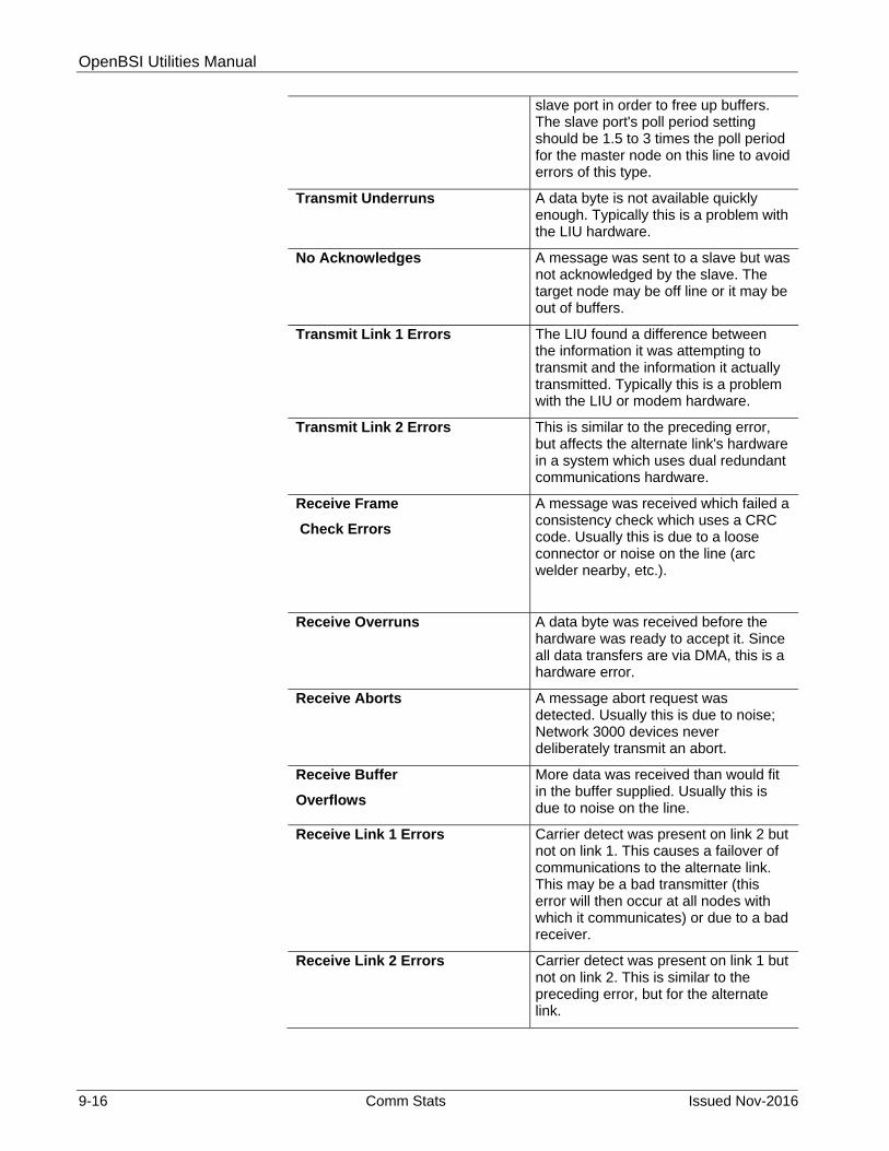
OpenBSI Utilities Manual
9-16 Comm Stats Issued Nov-2016
slave port in order to free up buffers. The slave port's poll period setting should be 1.5 to 3 times the poll period for the master node on this line to avoid errors of this type.
Transmit Underruns A data byte is not available quickly enough. Typically this is a problem with the LIU hardware.
No Acknowledges A message was sent to a slave but was not acknowledged by the slave. The target node may be off line or it may be out of buffers.
Transmit Link 1 Errors The LIU found a difference between the information it was attempting to transmit and the information it actually transmitted. Typically this is a problem with the LIU or modem hardware.
Transmit Link 2 Errors This is similar to the preceding error, but affects the alternate link's hardware in a system which uses dual redundant communications hardware.
Receive Frame
Check Errors
A message was received which failed a consistency check which uses a CRC code. Usually this is due to a loose connector or noise on the line (arc welder nearby, etc.).
Receive Overruns A data byte was received before the hardware was ready to accept it. Since all data transfers are via DMA, this is a hardware error.
Receive Aborts A message abort request was detected. Usually this is due to noise; Network 3000 devices never deliberately transmit an abort.
Receive Buffer
Overflows
More data was received than would fit in the buffer supplied. Usually this is due to noise on the line.
Receive Link 1 Errors Carrier detect was present on link 2 but not on link 1. This causes a failover of communications to the alternate link. This may be a bad transmitter (this error will then occur at all nodes with which it communicates) or due to a bad receiver.
Receive Link 2 Errors Carrier detect was present on link 1 but not on link 2. This is similar to the preceding error, but for the alternate link.

OpenBSI Utilities Manual
Issued Nov-2016 Comm Stats 9-17
Communications Front End (CFE) AUX Port Statistics
Note:` The CFE statistics described, below, are strictly for CFE 3385 or UCS 3380 units which use the IEEE-488 interface. Statistics for serial CFEs are identical to those for BSAP Slave units.
Field Description NAKs issued A message from the Console node is
NAKed if it must be discarded because a buffer is unavailable. Increasing the number of buffers may help. Unfortunately, the VAX systems can overrun the CFE. The VAX knows it did not get through and will retry; nothing is lost.
Message Discarded ACKs Issued
A message which is received by the CFE but whose ACK is not received by the Console is retransmitted by the Console. When the CFE detects this, it discards the duplicate message and advises the Console by issuing an 'ACK, msg discarded' response. This can be caused by noise on the line.
CRC Errors An incorrect CRC was received from the Console. The message was discarded and therefore retried from the Console. This is probably caused by noise or a temporarily unplugged cable.
Timeout Hardware Resets
The CFE has not received any message from the Console for 3 poll periods. All upgoing messages are flushed (like “aborted for transmit queue”) and the IEEE hardware is reset. This is probably caused by the cable being unplugged or the VAX Communications Task going down.
Out of Memory The IEEE multibus interface is having a memory access problem. This is a serious hardware problem with the CFE system or the IEEE 488 card.
Internet Protocol (IP) Port Statistics
The RTU maintains Internet Protocol (IP) statistics for each of its IP communications ports (either serial or Ethernet). In addition, the IP Statistics Window (later in this section) maintains RTU-wide statistics for IP communications.
Field Description Packets Received (Unicast)
The number of non-broadcast packets received at the current port. Packets Received includes both invalid packets (see RCV errors, below), and packets being routed

OpenBSI Utilities Manual
9-18 Comm Stats Issued Nov-2016
through the RTU, in addition to packets intended for this RTU.
Packets Sent (Unicast) The number of non-broadcast packets sent from the current port.
Characters Received The number of characters received at the port. This includes all protocol characters, and characters included within badly formed packets.
Packets Received (Multi) The number of broadcast packets received.These are most likely ARP requests on an Ethernet. ARP requests are used to determine the hardware (MAC) address for an IP address.
Rcv Messages Discarded
The number of packets discarded due to frame-check errors (such as invalid check-sums). For a serial I/O expansion rack on an RS-485 line this indicates CRC errors.
Rcv Messages (Errors) This is a catch-all error for invalid frames, which have been discarded. For a ControlWave host of serial I/O expansion racks on an RS-485 line this indicates a count of protocol errors, which are unexpected responses from the I/O expansion rack.
Rcv Messages (Bad Protocol)
The number of messages, with valid format and checksums, which have been discarded due to containing a protocol not supported by this RTU. For a serial I/O expansion rack on an RS-485 line this indicates a count of the number of non-I/O expansion rack messages forwarded to the current “Serial EXP Rack” port.
Characters Transmitted The number of characters sent out the port. This includes all protocol characters.
Packets Sent (Multi) The number of broadcast packets sent. These are most likely ARP requests on an Ethernet. ARP requests are used to determine the hardware (MAC) address for an IP address.
Send Errors A catch-all error for invalid send frames. These frames are discarded. Errors in this type include attempting to send a packet which is too large. For a ControlWave host of serial I/O expansion racks on an RS-485 line this indicates the number of times a timeout was seen while waiting for a response to a poll of an I/O expansion rack.

OpenBSI Utilities Manual
Issued Nov-2016 Comm Stats 9-19
9.5 Custom PROM Information Window (Network 3000)
The Custom PROM Information Window displays the contents of the Custom PROM area of a Network 3000 controller.
To access the Custom PROM Information Window, click the icon, shown above, or click Statistics > Custom Prom.
Figure 9-12. Custom Prom Information dialog box
The window displays, in abbreviated form, the name of each custom communication Protocol which is installed in the custom area of the Network 3000 controller. The number of protocols installed appears in the Entries field. Use the scroll bar to view entries which do not fit in the window. The Mode value is the number you must enter in the ACCOL Custom Module to designate which protocol you want to use. For the mode values of the most popular protocols, and configuration information for those protocols see the ACCOL II Custom Protocols Manual (document# D4066).
Product is an identification string for the custom firmware, as specified in the Custom PROM area. PCP is the proper identification string for custom firmware.
Firmware Version provides information about the type of custom firmware, and is typically one of the following values:

OpenBSI Utilities Manual
9-20 Comm Stats Issued Nov-2016
3 firmware is 186-based pre-version AE.00 5 firmware is 186-based, version AE.00 through AJ.10 7 firmware is 186-based AK or newer or 386EX Real Mode 8 firmware is 386EX Protected Mode
Link Date and Checksum are the firmware link date and data checksum value. Support personnel can use this information to verify PROM revision information.
Prom Version version is encoded as:
aa.bb.cc
where:
aa is the firmware version
bb is the update revision
cc indicates the beta revision
for example PCP00 with no updates or beta revisions appears as 00.00.00.

OpenBSI Utilities Manual
Issued Nov-2016 Comm Stats 9-21
9.6 Version Information Window
The Version Information Window displays details on the version of software and firmware used with the given controller. Support personnel may request this information to determine the revision of software and firmware used at a particular customer site. To access the Version Information Window, click the icon, shown above, or click Statistics>Version Info.
Figure 9-13. Version Information dialog box
The MSD and PEI values are used, respectively, to identify discrepancies between the file version of the control strategy executing in the controller, and the version originally downloaded. In general, these values are the same. If they are different, the discrepancy indicates that either an on-line edit has been made, or a file has become corrupted.
ACCOL Load indicates the version of ACCOL Tools software used to create this ACCOL load. (Only applies if this device uses ACCOL II.)List is the list version (used by legacy Trolltalk PC Network Monitor software).
Feature ID is used by old versions of the ACCOL Tools, to coordinate firmware revisions. Possible values are:
FE - AA firmware and newer
0 - S.1 through S.3 firmware (3350/3380/3385)
FF - Pre-S firmware (3350/3380/3385)
Not applicable
Runtime System refers to the firmware version installed, and Runtime System [Page 0] refers to the firmware revision of the control strategy file. In general, for all features to work, these should match; a discrepancy may indicate a possible incompatibility. Possible hexadecimal values for these fields are:
1 - 3350/3380/3385 loads (4.2 Tools/S3 firmware, or earlier)
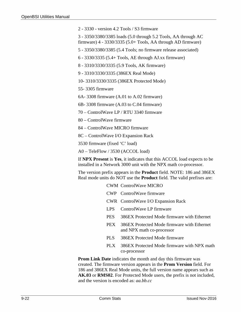
OpenBSI Utilities Manual
9-22 Comm Stats Issued Nov-2016
2 - 3330 - version 4.2 Tools / S3 firmware
3 - 3350/3380/3385 loads (5.0 through 5.2 Tools, AA through AC firmware) 4 - 3330/3335 (5.0+ Tools, AA through AD firmware)
5 - 3350/3380/3385 (5.4 Tools; no firmware release associated)
6 - 3330/3335 (5.4+ Tools, AE through AJ.xx firmware)
8 - 3310/3330/3335 (5.9 Tools, AK firmware)
9 - 3310/3330/3335 (386EX Real Mode)
10- 3310/3330/3335 (386EX Protected Mode)
55- 3305 firmware
6A- 3308 firmware (A.01 to A.02 firmware)
6B- 3308 firmware (A.03 to C.04 firmware)
70 – ControlWave LP / RTU 3340 firmware
80 – ControlWave firmware
84 – ControlWave MICRO firmware
8C – ControlWave I/O Expansion Rack
3530 firmware (fixed ‘C’ load)
A0 – TeleFlow / 3530 (ACCOL load)
If NPX Present is Yes, it indicates that this ACCOL load expects to be installed in a Network 3000 unit with the NPX math co-processor.
The version prefix appears in the Product field. NOTE: 186 and 386EX Real mode units do NOT use the Product field. The valid prefixes are:
CWM ControlWave MICRO
CWP ControlWave firmware
CWR ControlWave I/O Expansion Rack
LPS ControlWave LP firmware
PES 386EX Protected Mode firmware with Ethernet
PEX 386EX Protected Mode firmware with Ethernet and NPX math co-processor
PLS 386EX Protected Mode firmware
PLX 386EX Protected Mode firmware with NPX math co-processor
Prom Link Date indicates the month and day this firmware was created. The firmware version appears in the Prom Version field. For 186 and 386EX Real Mode units, the full version name appears such as AK.03 or RMS02. For Protected Mode users, the prefix is not included, and the version is encoded as: aa.bb.cc

OpenBSI Utilities Manual
Issued Nov-2016 Comm Stats 9-23
where: aa is the firmware version
bb is the update revision
cc indicates the beta revision
for example PLS00 with no updates or beta revisions would appear as 00.00.00.
Protected mode units also contain the Boot Prom Version and Boot Prom Link Date.
The On-Board Serial EEProm button allows you to view identification strings associated with I/O boards in a ControlWave-series controller. (NOTE: These identification strings must already exist as system variables in the ControlWave Designer project _Sn_IO_BOARD_ID_STR where n is the slot number of the I/O board.) For more information on these please see System Variables in the ControlWave Designer Programmer’s Handbook (document# D5125).
9.7 Node Routing Table Window
NetView software generates a Node Routing Table (NRT) that includes the addresses of each node in the network. This information is essential for network communications to function. Each node in the network holds a unique copy of the Node Routing Table, which the system specifically modifies for that node. The Node Routing Table Window presents details on the Node Routing Table residing in the controller including the current node's global address, NRT version number, as well as up/down routing information for global messages.
To access the Node Routing Table Window, click the icon, shown above, or click Statistics>Node Routing Table.
Figure 9-14. Node Routing Table dialog box

OpenBSI Utilities Manual
9-24 Comm Stats Issued Nov-2016
The global address of this controller (node) appears in the GLAD field. The level of the node appears in the Current Level field.
Support personnel may use the remaining information in the window may for trouble-shooting network communication problems.
9.8 Internet Protocol (IP) Statistics Window
The Internet Protocol (IP) Statistics Window displays information on IP communication activity.
Note: Typically, you only need to concern yourself with this information if you need to implement a non-standard IP network configuration.
To access the IP Statistics Window, click the icon, shown above, or click Statistics>IP Statistics.
Figure 9-15. Internet Protocol Statistics dialog box
IP statistics are divided up into categories because IP communications involves several different inter-related communication protocols. All of these protocols must function together properly in order for data to be transferred through the network intact.
The Selected Protocol list box allows you to choose which portion of the IP statistics you want to access.
If you signed on at security level six, you can reset all Internet Protocol statistics using the Reset All.
Use this list box to select the type of IP protocol for which you want to view statistics.

OpenBSI Utilities Manual
Issued Nov-2016 Comm Stats 9-25
The various categories of statistics are described, below:
IP Statistics Decription
IP stands for Internet Protocol; it is a specification which defines the most basic packets of information transported in a TCP/IP network. IP provides addressing and packet routing mechanisms. The statistics maintained are:
Statistic Description Packets Received Shows the number of data packets received from the
MAC layer. This count includes invalid packets and packets destined for “pass-thru.” This count does not include packets discarded by the data-link due to checksums or length checks performed at that layer.
Received with Header Error
Shows a count of discards due to header errors. These include invalid IP data length, invalid IP version, and IP header checksum errors.
Received with invalid IP Address
Shows the number of times a packet was received which is not for the current RTU and the current RTU does not know how to route the packet to the contained address.
Packets Forwarded
Shows the number of receive packets not for the current RTU, which have been forwarded to another machine for processing.
Received with invalid Protocol
Shows the number of discards due to an unrecognized protocol code in the header.
Packets delivered to stack
Shows the number of packets properly received, and sent on to be processed by a protocol handler.
Packet send attempts
Shows the number of packets which the IP layer has been asked to send. This includes discards. Note: This count does not include send attempts which are discarded by UDP or other higher-level layers.
Send Packets Discarded
Shows the number of packets discarded due to badly formed packets (length errors, bad destination, etc.)
Send Packets (No Route)
Shows the number of packets discarded because there is no known route to the destination address. Also, increments the “discarded” statistic.
Packet Fragments Received
A data-link does not support sending of an entire large packet in one section; therefore, the source machine has broken it into fragments. This is the total number of these fragments received.
Packets assembled from fragments
Shows the number of packets which have been put together from fragments.

OpenBSI Utilities Manual
9-26 Comm Stats Issued Nov-2016
Reassembly of packet failed
Shows the number of times a packet has been discarded due to not receiving all of its fragments within the allotted time.
Send Packet fragmented OK
A MAC layer (PPP on serial or Ethernet) on the current RTU cannot support sending of full-size packets. This is the number of packets which have been split into fragments for sending.
Failed to get packet for fragment
Shows the number of times a packet has been discarded due to the IP layer not being able to allocate a send packet for the fragment.
Number of send Fragments
Shows the number of packet fragments which have been sent out a data-link.
Default time to live
Shows the number of "hops" (sends over data-links) a packet can have before it is discarded. This is not a statistic; but, a display of the default value used by this RTU.
Timeout for packet Reassembly
Shows the time between the arrival of the first fragment of a packet to when all fragments must arrive. If the fragments all do not arrive, the fragments are discarded. This is not a statistic; but, a display of the default value used by this RTU.
ICMP Statistics Description
ICMP is a low-level IP protocol which performs notification of communications events. The statistics defined are:
Statistic Description Packets received Shows a count of protocol packets received by this RTU.
This includes discards.
Receive packets discarded
Shows a count of packets this RTU discarded due to length error, ICMP checksum, or invalid request type.
Destination unreachable packet received
Shows a count of instances where a packet was sent from this RTU to a destination (either IP address or Protocol Port) which could not be reached.
Time to Live Exceeded packet received"
Shows a count of instances where a packet was sent from this RTU which was transmitted over too many data-links on the way to its destination (and was discarded).
Redirect packets received
Shows a count of requests received by this RTU to modify internal routing information based on a routing machine determining a better path for a previously sent message.

OpenBSI Utilities Manual
Issued Nov-2016 Comm Stats 9-27
Echo Request packets received
Shows a count of PING requests received by this RTU. PING is a program which sends a simple ECHO packet to another IP machine to determine if communications is possible.
Echo Reply packets received
Shows the number of replies received to “PING” requests made by this RTU.
Time stamp request packet received
Shows the number of requests for a timestamp received by this RTU. Note: This is not the RTU time-synch request.
Packets Sent Shows the total number of ICMP packets sent by this RTU. Does not include discards.
Out packets discarded
Show the count of messages discarded by this RTU due to not being able to allocate send packet.
Destination unreachable packets sent
Shows a count of packets that could not be delivered or forwarded. A notification was sent back to the originator of the packet.
Time to live exceeded packets sent
Shows a count of instances where when forwarding a packet, its time-to-live count was exhausted; a notification was sent back to the originator of the packet.
Redirect packets sent
Shows a count of instances where, when forwarding a packet out the same line it was received over, a notification is sent back to the originating node that a better path is available.
Echo request packets sent
Shows a count of PING requests sent by this RTU.
Echo reply packets sent
Shows a count of PING responses sent by this RTU.
UDP Statistics Description
UDP stands for User Datagram Protocol. UDP is a method of transmitting user data from one Protocol Port on a computer to another (either on the same or another computer). UDP provides a checksum on the data sent; but, does not guarantee delivery. UDP is connectionless, there is no need to establish a connection before sending data.
Statistics available are as follows:
Statistic Description
Packets received Shows a count of packets received and processed. Does not include discards.

OpenBSI Utilities Manual
9-28 Comm Stats Issued Nov-2016
Port not present Shows a count of instances where a packet was discarded because it was destined for an undefined Port. An ICMP error packet is returned.
Receive packet discarded
Shows a count of packets discarded due to header or checksum errors.
Packets sent Shows a count of packets sent to the IP layer for processing.
IBP Statistics Description
IBP stands for Internet Bristol Protocol. It is the protocol used inside UDP packets to perform reliable data communication between OpenBSI workstations and ControlWave or Network 3000 IP RTUs. This communication method allows both detection and retry of missed packets, and proper ordering of requests. In addition, multiple requests (sub-packets) can be combined into a single network packet.
The statistics defined are:
Statistic Description No connection available
Shows a count of the number of packets dropped due to not being able to find an inactive connection.
Total discards based on mult ACK tmo
Shows a count of the number of packets discarded due to exceeding the ACK timeout limit.
ACK timeouts Shows a count of the number of times that an ACK for a packet was not received within the timeout.
Discarded by purge operations
Shows a count of the number of packets discarded due to connection inactivity.
Discarded due to quota
Shows a count of the number of packets discarded at this RTU due to a shortage of available network packets.
Discarded due to sequence #
Shows a count of the number of packets discarded at this RTU due to sequence #s which were not in the proper range. Note: This can include packets which were re-sent due to timeout, but already received.
Invalid form for packet
Shows a count of the number of packets received with an invalid header length.
Invalid identifier for sub-packet
Shows a count of the number of sub-packets detected with invalid type code.
Packets received out-of-order
Shows a count of the number of packets which were received out of sequence (and thus loaded onto the out-of-order list). Items are removed from the list when the preceding packets are received.

OpenBSI Utilities Manual
Issued Nov-2016 Comm Stats 9-29
Packets accepted Shows a count of the number of IBP packets accepted for processing.
Packets sent Shows a count of the number of IBP packets given to theIP stack for send.
Restart connection
Shows a count of the number of times an IBP packet was received which indicated that the local sequence number should be reset.
Errors attempting to send packet
Shows a count of the number of times the IP stack issued an error while trying to send a packet
Sub-packets received
Shows a count of the number of IBP sub-packets received from the IP stack.
Sub-packets sent Shows a count of the number of IBP sub-packets given to the IP stack for sending.
9.9 Printing the Entries in the Current Window
You can print the textual data collected in the various Communication Statistics window on a printer.
Note: Before attempting to print, a printer must be properly configured, and connected to this workstation, either directly, or through a network. The Windows Print Setup dialog box, which is used for this configuration, is accessible by clicking on Statistics>Print Setup.
To print the entries (data) in the window, click the printer icon, shown above, or click Statistics>Print. The Windows Print dialog box opens. See your Windows documentation for further information.
9.10 Exporting Data Entries to the Windows® Clipboard
As an alternative to sending data to the printer, described above, you can copy entries as text into the WindowsJ Clipboard. From the Clipboard, you can export the data to other WindowsJ applications such as spreadsheets or word processors. The data is specifically formatted for use in Microsoft7 Excel.
To copy entries to the Windows® Clipboard, click Statistics>Copy to Clipboard.
See your Windows® documentation for more information on using the Clipboard.

This page is intentionally left blank
OpenBSI Utilities Manual
Issued Nov-2016 Signal Writer 10-1
Chapter 10 – Using Signal Writer
Signal Writer allows the OpenBSI workstation to automatically send signal values to a controller, at a pre-defined interval. This provides a way for external applications to send data to the controller.
In This Chapter
10.1 Starting Signal Writer ..................................................................... 10-1 10.2 Setting Up Signal Writer Configuration Parameters ...................... 10-2 10.3 Signal Writer File Formats ............................................................. 10-3
10.3.1 Write Signal File ................................................................. 10-3 10.3.2 Write List File ...................................................................... 10-3
You specify the signal values to be sent in ASCII text files, either as a group of individual signals, or as a list of signals. In either case, all signals in a given file must be for the same controller. At a pre-defined interval, the Signal Writer utility scans a specified directory for these ASCII text files; for each such file it finds, Signal Writer writes those signal values in the file to corresponding signals in the controller. After Signal Writer performs the write operation, it deletes the file.
10.1 Starting Signal Writer
Note: Before starting Signal Writer, you must sign on using NetView with sufficient security privileges (Engineer or Administrator). Otherwise, OpenBSI prevents you from using this utility.
Click Start>Programs>OpenBSI Tools>Common Programs >Signal Writer. The Signal Writer Tool starts in a minimized state. Restore thewindow on the screen. The Signal Writer window displays data on theexecution of Signal Writer and provides access to Signal WriterConfiguration Parameters.

OpenBSI Utilities Manual
10-2 Signal Writer Issued Nov-2016
Figure 10-1. Signal Writer
10.2 Setting Up Signal Writer Configuration Parameters
You define Signal Writer configuration parameters in the Write Parameters dialog box. To access this dialog box, click Setup>Write Parameters.
Figure 10-2. Write Parameters dialog box
The Signal Writer configuration parameters are:
Field Description
Directory Specifies the drive and directory (folder path) which Signal Writer scans for ASCII files containing signal data. (The formats for these files are discussed later.) Once Signal Writer completes writing file data to a controller, it automatically deletes the file.
Retry times before failing
Shows the number of attempts Signal Writer makes to write data to the controller. Once Signal Writer makes this number of attempts without success, it declares a failure in the Status field.
Time of last write to RTU Type of file: Signal (*.WSG) or List (*.WLS)
RTU node name Status of write attempt

OpenBSI Utilities Manual
Issued Nov-2016 Signal Writer 10-3
Check file every # seconds
Shows the scan interval, in seconds, at which Signal Writer checks the Directory for new ASCII files.
10.3 Signal Writer File Formats
Each ASCII signal data file which Signal Writer uses must be in either write list file or write signal file format. You can use both types of files but you cannot mix both formats in the same file.
10.3.1 Write Signal File
A Write Signal file must be named
node.WSG
where the file base name of node is the node name of the controller to be written to, and WSG is the file extension. The first line of the WSG file must be an integer specifying the number of signals in the file. Each of the remaining lines of the file must consist of a signal name, and a signal value, separated by a space. You can enter either analog or logical signals; string signals are not supported. If you use a logical signal, its value must be either ON/OFF or TRUE/FALSE.
The example file, below, shows a Write Signal file created for the node called DPU5. Its Write Signal file must therefore be named DPU5.WSG.
Figure 10-3. Sample WSG File
10.3.2 Write List File
To use a Write List file, the signals being written to must exist in a signal list, and you must know their position in the list.
A Write List file must be named
node.WLS
where the file base name of node is the node name of the controller which will be written to, and WLS is the file extension.
The format of the Write List File is presented below:
n number of list definitions in this Write List File list definition 1
3 VALVE01.OPEN.NOW TRUE PUMP01.POWER.ON ON SETPOINT.WATER.TEMP 32

OpenBSI Utilities Manual
10-4 Signal Writer Issued Nov-2016
list definition 2 : list definition n
where a list definition consists of:
the number of the signal list the starting index into the list x number of signals being written to value 1 value 2 . value x
Values in the definition must be consecutive. They can be analog values; or for logical signals, either ON/OFF or TRUE/FALSE.
The example below shows a Write List file created for the node called RTU3. Its Write List File must therefore be named RTU3.WLS.
The first line of the RTU3.WLS file indicates that it contains two list definitions.
The first list definition applies to signal list 1 in RTU3, and will write to two consecutive list entries, starting with the fifth entry in the list. It will write a value of 1.9 to the fifth entry in list 1, and a value of TRUE to the sixth entry in list 1.
The second list definition applies to signal list 27 in RTU3. It will write to 3 consecutive list entries, starting with the eighth entry in the list. It will write a value of ON to the eighth entry of list 27, a value of 1001 to the ninth entry of list 27, and a value of 45 to the tenth entry of list 27.
File Entry in RTU3.WLS Explanation
2 number of list definitions 1 list definition for signal list 1 5 start with 5th signal in signal list 1 2 write values to 2 consecutive signals, i.e.
signal 5 and 6 in list1 1.9 signal 5 value TRUE signal 6 value 27 list definition for signal list 27 8 start with 8th signal in signal list 27 3 write values to 3 consecutive signals, i.e.
signals 8, 9, and 10 ON signal 8 value 1001 signal 9 value 45 signal 10 value

OpenBSI Utilities Manual
Issued Nov-2016 Alarm Router 11-1
Chapter 11 – Using Alarm Router
The Alarm Router allows you to view alarms, on the screen, in an Alarm Window. It also provides a capability to export alarm data to files, or to other HMI/SCADA packages which support alarm management, such as Iconics AlarmWorX+™ software.
In This Chapter
11.1 Starting Alarm Router .................................................................... 11-2 11.2 How is the Alarm Router Configured? ........................................... 11-2 11.3 Specifying Initialization Parameters and Choosing DLLs .............. 11-3
11.3.1 Parameter Configuration Page ........................................... 11-3 11.3.2 DLL Configuration Page ..................................................... 11-5 11.3.3 Activating A DLL ................................................................. 11-5 11.3.4 Removing A DLL From the Configured DLLs List Box ....... 11-5 11.3.5 Installing An All New DLL ................................................... 11-6 11.3.6 Removing A DLL from the Available DLLs List Box ........... 11-6
11.4 Configuring Alarm Router DLLs ..................................................... 11-6 11.4.1 ALMTEXT DLL ................................................................... 11-7 11.4.2 ALMWORX DLL ................................................................. 11-8
11.5 Viewing Alarms in the Alarm Window .......................................... 11-10 11.5.1 Acknowledging Selected Alarms in the Alarm Window .... 11-13 11.5.2 Changing the Font Used in the Alarm, Error, and Monitor
Windows ......................................................................... 11-14 11.6 Viewing Status Messages in the Monitor Window ....................... 11-15
11.6.1 List of Monitor Window Status Msgs & Their Meanings ... 11-16 11.7 Viewing Error Messages in the Error Window ............................. 11-17
11.7.1 Clearing Errors from the Error Window ............................ 11-18 11.7.2 List of Error Messages and Their Meanings .................... 11-18
11.8 Starting Alarm Processing ........................................................... 11-19 11.9 Stopping Alarm Processing ......................................................... 11-19 11.10 Printing Entries in Alarm Router Windows ................................... 11-19 11.11 Shutting Down the Alarm Router ................................................. 11-19 11.12 Editing the Configuration Files ..................................................... 11-19
11.12.1 ALARMRTR.INI File ........................................................ 11-20 11.12.2 ALMTEXT.INI File ........................................................... 11-20 11.12.3 ALMWRX.INI File ............................................................ 11-20
11.13 Program Messages ...................................................................... 11-21
You accomplish export of alarm data through one or more special sub-programs, called DLLs, which are specifically configured for alarm export. If an error occurs during an attempt to export alarm data, Alarm Router makes additional attempts, based on user-specified parameters. If these attempts fail, Alarm Router disables the DLL causing the error, and saves the pending alarm data in a file for later retrieval.
Note: DLLs is an abbreviation for Dynamic Link Libraries. DLLs are software procedures and sub-routines which are activated to perform a certain function; in this case, they are used to export alarm data
Status messages concerning operation of the Alarm Router are reported in the Monitor Window.

OpenBSI Utilities Manual
11-2 Alarm Router Issued Nov-2016
Running - Alarm exporting is active
Stopped - Alarm exporting is turned OFF.Stopping - Alarm exporting is stopping.
Starting - Alarm exporting is starting.
number of alarms
number of status messages
number of error messages(if this appears in RED there are more errors than can be displayed.)
11.1 Starting Alarm Router
Figure 11-1. Alarm Router
Before you start Alarm Router, OpenBSI communications must already be active through either NetView, LocalView, or TechView.
Click Start > Programs > OpenBSI Tools > Common Tools > Alarm Router. Alarm Router starts collecting and processing alarm information. In addition, if AlarmWorX+ software is configured, and the ALMWORX DLL is installed, ALMWORX also starts.
11.2 How is the Alarm Router Configured?
Configuring the Alarm Router involves specifying certain setup parameters, and choosing which DLLs to use for alarm export. See Specifying Initialization Parameters and Choosing DLLs for details.
In addition, you may need to enter some DLL-specific parameters; they vary depending upon which DLLs you choose. See Configuring Alarm Router DLLs for details.
If desired, you can edit the configuration files directly, with a text editor, instead of using the dialog boxes described in this section. See Editing the Configuration Files for more information.

OpenBSI Utilities Manual
Issued Nov-2016 Alarm Router 11-3
11.3 Specifying Initialization Parameters and Choosing DLLs
The Alarm Router Configuration Setup dialog box is divided into two pages. You specify initialization parameters on the Parameter Configuration Page, and you select DLLs from the DLL Configuration Page. Use the file tabs to switch back and forth between the pages.
Before attempting to use this dialog box, you must halt all alarm processing. See Stopping Alarm Processing on page 11-19.
Note: If fields in the dialog box cannot be edited, it means you did NOT stop alarm processing prior to invoking this dialog box. Stop alarm processing, and then call up this dialog box again insert text
To access the Alarm Router Configuration Setup dialog box, click the Configure Application icon, shown above, -or- click File>Initialize. The Parameter Configuration page opens (see Figure 11-2.)
When finished editing both pages, click OK, on either page, to save all entries, or click Cancel to discard any changes.
You can now re-start alarm processing as described under Starting Alarm Processing on page 11-19.
Figure 11-2. Alarm Router Configuration Setup – Parameter Configuration
11.3.1 Parameter Configuration Page
The fields in the Parameter Configuration page of the dialog box are shown below:
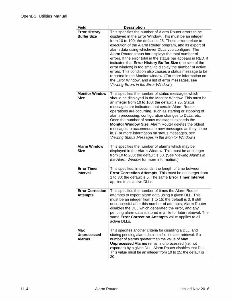
OpenBSI Utilities Manual
11-4 Alarm Router Issued Nov-2016
Field Description Error History Buffer Size
This specifies the number of Alarm Router errors to be displayed in the Error Window. This must be an integer from 10 to 100; the default is 25. These errors relate to execution of the Alarm Router program, and its export of alarm data using whichever DLLs you configure. The Alarm Router status bar displays the total number of errors. If the error total in the status bar appears in RED, it indicates that Error History Buffer Size (the size of the error window) is too small to display the number of active errors. This condition also causes a status message to be reported in the Monitor window. (For more information on the Error Window, and a list of error messages, see Viewing Errors in the Error Window.)
Monitor Window Size
This specifies the number of status messages which should be displayed in the Monitor Window. This must be an integer from 10 to 100; the default is 25. Status messages are indicators that certain Alarm Router operations are occurring, such as starting or stopping of alarm processing, configuration changes to DLLs, etc. Once the number of status messages exceeds the Monitor Window Size, Alarm Router deletes the oldest messages to accommodate new messages as they come in. (For more information on status messages, see Viewing Status Messages in the Monitor Window.)
Alarm Window Size
This specifies the number of alarms which may be displayed in the Alarm Window. This must be an integer from 10 to 200; the default is 50. (See Viewing Alarms in the Alarm Window for more information.)
Error Timer Interval
This specifies, in seconds, the length of time between Error Correction Attempts. This must be an integer from 1 to 30; the default is 5. The same Error Timer Interval applies to all active DLLs.
Error Correction Attempts
This specifies the number of times the Alarm Router attempts to export alarm data using a given DLL. This must be an integer from 1 to 15; the default is 3. If still unsuccessful after this number of attempts, Alarm Router disables the DLL which generated the error, and any pending alarm data is stored in a file for later retrieval. The same Error Correction Attempts value applies to all active DLLs.
Max Unprocessed Alarms
This specifies another criteria for disabling a DLL, and storing pending alarm data in a file for later retrieval. If a number of alarms greater than the value of Max Unprocessed Alarms remains unprocessed (i.e. not exported) by a given DLL, Alarm Router disables that DLL. This value must be an integer from 10 to 25; the default is 20.

OpenBSI Utilities Manual
Issued Nov-2016 Alarm Router 11-5
DLL Configuration Page
You use the DLL Configuration Page to view a list of available DLLs, and to activate them after you configure them.
Figure 11-3. Alarm Router Configuration Setup – DLL Configuration
The Available DLLs list box shows which DLLs are present. Both the ALMTEXT DLL and the ALMWORX DLL come with the Alarm Router software. You can only configure the ALMWORX DLL, however, if the AlarmWorX+ software is already installed on the PC.
11.3.2 Activating A DLL
You should only activate DLLs if they have already been configured (see Configuring Alarm Router DLLs). To activate an existing DLL, click on its name in the Available DLLs list box, and click Add. If the DLL exists, Alarm Router adds it to the Configured DLLs list box. To activate all available DLLs, make sure no DLLs are selected, then click Add All. All DLLs in the Available DLLs list box are activated, and displayed in the Configured DLLs list box.
11.3.3 Removing A DLL From the Configured DLLs List Box
If you have to disable a DLL, click on its name in the Configured DLLs list box, then click Remove. To remove all DLLs from the Configured DLLs list box, make sure none are selected, then click Remove All. Alarm Router prompts you to confirm that all DLLs should be removed.

OpenBSI Utilities Manual
11-6 Alarm Router Issued Nov-2016
11.3.4 Installing An All New DLL
If you develop a DLL of your own, and need to install it, copy it in into whichever directory is used for the OPENBSI program files. Next, click Add New DLL.
Figure 11-4. Installing an all New Alarm RouterDLL
Alarm Router prompts you to enter the name of the new DLL in the DLL Support Modification dialog box. Type its name and click OK. Alarm Router adds the DLL to the Available DLLs list box. Now you must configure it according to instructions in Configuring Alarm Router DLLs.
11.3.5 Removing A DLL from the Available DLLs List Box
To remove a DLL from the Available DLLs list box, first remove it from the Configured DLLs list box, as described above, then click Remove DLL. Alarm Router prompts you to enter the name of the DLL you want to remove in the DLL Support Modification list box, then click OK.
Figure 11-5. Removing an Alarm Router DLL
11.4 Configuring Alarm Router DLLs
Before activating a DLL, you must configure it. For the ALMTEXT and ALMWORX DLLs, the Alarm Router automatically performs the configuration for you; you need not change it unless you want to alter the defaults.

OpenBSI Utilities Manual
Issued Nov-2016 Alarm Router 11-7
11.4.1 ALMTEXT DLL
This DLL collects alarm data, and exports it to a text file in the format shown below.
Figure 11-6. Sample ALMTEXT output
To change the defaults for this DLL, click the Configure DLL icon, shown above, -or- click File> Configure. The Dll Configuration Selection dialog box opens. Choose ALMTEXT from the list box and click OK.
Figure 11-7. DLL Configuration Selection
Figure 11-8. Alarm Text DLL Configuration dialog box
19-MAR-2007 09:35:30.1 ????:#OCTIME.ERROR. Alarm Single Crit ON T-ALM
19-MAR-2007 09:35:30.1 ????:#OCTIME.ERROR. Alarm Single Crit ON T-ALM
19-MAR-2007 09:51:30.0 L1C2:#LINE.000. Alarm Single Crit ON T-ALM
19-MAR-2007 13:06:56.4 L1C2:#LINE.000. NoAlm OFF T-ALM
19-MAR-2007 13:06:55.5 L1C2:#OCTIME.ERROR. NoAlm OFF T-ALM

OpenBSI Utilities Manual
11-8 Alarm Router Issued Nov-2016
The Alarm Text Dll Configuration dialog box opens. The Enter File Path Name field allows you to specify the drive and directory which will contain the alarm data text file. The Enter Alarm File Name field allows you to specify the name of the alarm data file; the default name is ALMTEXT.ALM.
The Select File Option list box lets you specify whether Alarm Router should create a new alarm data text file for each execution of the ALMTEXT DLL, or whether it should append the existing file when new data is exported.
Click OK to save your changes.
11.4.2 ALMWORX DLL
The ALMWORX DLL requires Iconics AlarmWorX+™ software. You must configure it as described, below, and then add it to the list of Configured DLLs in the Alarm Router Configuration Setup dialog box.
Figure 11-9. DLL Configuration Selection
To change the defaults for this DLL, click the Configure DLL icon, shown previously, -or- click File >Configure. The Dll Configuration Selection dialog box opens. Choose ALMWORX from the list box and click OK.

OpenBSI Utilities Manual
Issued Nov-2016 Alarm Router 11-9
In the “AlarmWorX+ Configuration” section, use the Path Name field to specify the drive and directory where the AlarmWorX+ software is installed. Use the File Name field to specify the executable file used by AlarmWorX+. If you check the Stop AlarmWorx+ upon Alarm Router Exit box, the AlarmWorX+ package shuts down whenever the Alarm Router is shutdown.
Use the DDE Configuration section to set up DDE communications with the Iconics AlarmWorX+ package.
Note: Do NOT confuse DDE Configuration with the OpenBSI DDE Server. These DDE parameters are used only by the AlarmWorX+ package; they are totally unrelated to the OpenBSI DDE Server software.
Figure 11-10. Alarm WorX+ DLL Configuration
You must specify ALARMRTR as the Server; you must also specify this in the MUX Link Source field in the Input Page of the System Preferences Screen in AlarmWorX+. Similarly, configure the Topic and Item fields to match the MUX Link Topic and MUX Link Item fields in AlarmWorX+.
Use the Error File Options fields to specify an error file the Alarm Router uses to store un-processed alarm data as text in the event exporting using the ALMWORX DLL fails. The Path Name specifies the drive and directory in which Alarm Router creates the error file, and File Name specifies the name of the error file. Choose either APPEND or NEW from the File Option list box to determine whether Alarm Router should create a new error file on each failed execution of the ALMWORX DLL, or whether it should append the existing error file.
After you make these entries, you must perform additional configuration within AlarmWorX+. You must define each ACCOL analog or logical alarm signal name (node.base.extension.attr) as a “Tag” within AlarmWorX+. Some notes about configuring tags are included below;

OpenBSI Utilities Manual
11-10 Alarm Router Issued Nov-2016
see the Iconics AlarmWorX+ documentation for more information on these subjects.
Notes About Configuring Alarms in Iconics AlarmWorX+
Two methods are available for configuring the AlarmWorX+ data base. The first method allows you to enter signals into the alarm configuration page on a signal by signal basis which creates a Microsoft Access® data base. The second, and somewhat faster method, is to directly enter the alarm parameters in the Access table.
Figure 11-11. Iconics Alarm WorX+ Configuration
Configuring an alarm is a simple fill-in-the-blanks procedure:
The Tag field is the ACCOL signal name connection point which the Alarm Router uses to pass the ACCOL alarm to AlarmWorX+. Its format is node.base.extension.attr. The Base Text field can be any text or alarm descriptor, typically the ACCOL signal name is used in the same form as the Tag.
You can change all parameters, including the alarm limits, at any time from the menu or through the Access table database.
Alarms reported to AlarmWorX+ which are not in the data base are still displayed in the Alarm Summary display, with all parameters, including the ACCOL signal name, but they are identified as “Unknown Tags” in the description field. All alarms, whether or not they are in the data base, are time-stamped.
11.5 Viewing Alarms in the Alarm Window
To call up the Alarm Window, click the View Alarm Window icon, shown at left, -or- click View>Alarm Window. The Alarm Window opens. The most recent alarms always appear at the top of the window. The Alarm Window Size parameter in the Alarm Router Configuration Setup dialog box determines the number of alarms visible in the window.

OpenBSI Utilities Manual
Issued Nov-2016 Alarm Router 11-11
Figure 11-12. Alarm Window
If you see a signal in an alarm state named nodename:COMM.STATUS. this is a signal from OpenBSI (not from the RTU) that communications have been lost with the top level RTU named nodename.
For Network 3000 users, the entries in the alarm window vary depending upon the value of the #ALARM.FORMAT. and #ALARM.FORMAT.001 system signals in the ACCOL load.
The full extended signal formats for analog and logical signals are shown on the next two pages.

OpenBSI Utilities Manual
11-12 Alarm Router Issued Nov-2016
The format of an analog alarm message is:
Figure 11-13 Analog Alarm Message Format

OpenBSI Utilities Manual
Issued Nov-2016 Alarm Router 11-13
The format of a logical alarm message is:
Figure 11-14. Logical Alarm Format
11.5.1 Acknowledging Selected Alarms in the Alarm Window
Before you can do any alarm acknowledgment through Alarm Router, you must sign on, in NetView, with either Engineer or Administrator privileges. Otherwise, you cannot acknowledge alarms.
Selecting the Alarms
To select a single alarm, click on the alarm in the Alarm Window. To select multiple alarms, hold down the [Ctrl] key, and click on each alarm you want to select. If there are multiple alarms which are contiguous, drag the mouse to highlight them.

OpenBSI Utilities Manual
11-14 Alarm Router Issued Nov-2016
Figure 11-15. Selecting Alarms
Acknowledging all of the Alarms You Select
To acknowledge the currently selected alarms, click the Ack Selected Alarms icon, or click Acknowledge>Selected.
The Monitor Window (not the Alarm Window) displays a message confirming the acknowledgment for alarms from a particular RTU.
Note: Alarm processing need not be active in order to perform acknowledgments.
11.5.2 Changing the Font Used in the Alarm, Error, and Monitor Windows
You can change the font, point size, etc. of data appearing in the Alarm, Error, and Monitor windows for the current session by clicking Format>Font. Make your selections and click OK when finished.
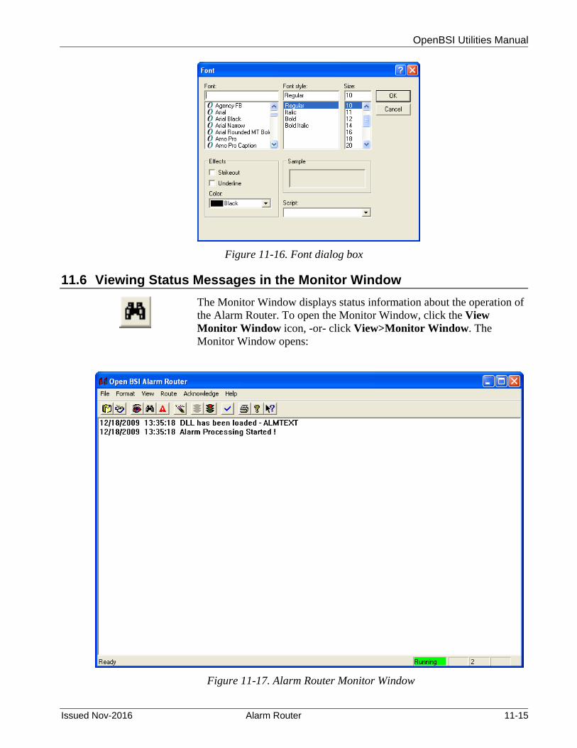
OpenBSI Utilities Manual
Issued Nov-2016 Alarm Router 11-15
Figure 11-16. Font dialog box
11.6 Viewing Status Messages in the Monitor Window
The Monitor Window displays status information about the operation of the Alarm Router. To open the Monitor Window, click the View Monitor Window icon, -or- click View>Monitor Window. The Monitor Window opens:
Figure 11-17. Alarm Router Monitor Window

OpenBSI Utilities Manual
11-16 Alarm Router Issued Nov-2016
Older status messages appear at the top of the window; newer ones appear towards the bottom. Each message is preceded by a timestamp showing when it was initially sent.
The Monitor Window Size parameter in the Alarm Router Configuration Setup dialog box determines the number of status messages appearing in the window.
11.6.1 List of Monitor Window Status Messages and Their Meanings
Status Message: Meaning: Alarm Processing Started! The Alarm Router is active and ready to
export alarm data using configured DLLs. Alarm Processing Stopped! All export of alarm data is stopped. Alarms were successfully acknowledged at node nodename.
One or more alarms from RTU nodename were acknowledged.
DLL added to the configuration list - DLLname
A DLL has been added to the Configured DLLs list box in the Alarm Router Configuration Setup dialog box.
DLL has been loaded - DLLname
Alarm processing is beginning using this DLL.
DLL has been unloaded - DLLname
Alarm processing using this DLL is being stopped.
DLL removed from configuration list - DLLname
A DLL has been removed from the Configured DLLs list box in the Alarm Router Configuration Setup dialog box.
Error Informing Driver to Stop Routing Alarms! Process is Continuing to Shutdown.
Alarm processing is being stopped, and an error has occurred. Alarm processing will still be stopped.
An error occurred sending an alarm ack message to node nodename.
An alarm at RTU nodename could not be acknowledged due to either the RTU, or the top-level RTU for this part of the network, being off-line.
The Error Window is Full! Please Clear It.
There are more errors than can fit in the Error Window. Review the errors, then clear errors as described under Clearing Errors From the Error Window.
Invalid node name encountered while acking alarms. Node = nodename
Alarms cannot be acknowledged from RTU nodename because the node routing table (NRT) at the RTU and at the PC are inconsistent (Node Routing Table mismatch).
A load version error occurred while acking alarms at node nodename.
A load version mismatch has occurred between the alarm being acknowledged and the ACCOL load at RTU nodename. This may occur if a new ACCOL load was downloaded at the RTU, and the alarm being acknowledged was from the previous load version.

OpenBSI Utilities Manual
Issued Nov-2016 Alarm Router 11-17
Status Message: Meaning: Max attempts to write to DLL exceeded - DLLname. Check file FAILURE.ALM for unprocessed alarms.
The number of attempts to export using the named DLL has exceeded the Error Correction Attempts value in the Alarm Router Configuration Setup dialog box. This DLL will be disabled, and the unprocessed alarms will be stored in the file FAILURE.ALM.
No Dll’s configured for export!!! Alarm Router Stopping!
This error occurs if all DLLs have been disabled because of export errors. Alarm processing will cease.
Number of unprocessed alarms for DLL has been exceeded - DLLname. Check file FAILURE.ALM for unprocessed alarms.
The number of unprocessed alarms has exceeded the Max Unprocessed Alarms value specified in the Alarm Router Configuration Setup dialog box. This DLL will be disabled, and the unprocessed alarms will be stored in the file FAILURE.ALM.
On-line reconfiguration of DLL has taken place - DLLname
A change has been made in the configuration of this DLL.
A timeout occurred while acknowledging alarms at node nodename.
One or more messages indicating the acceptance of the operator alarm acknowledgment from RTU nodename have not been received within the expected time period.
11.7 Viewing Error Messages in the Error Window
To call up the Error Window, click the View Error Window icon, shown at left, -or- click View>Error Window. The Error Window opens. The Error Window displays error messages concerning operation of the alarm export DLLs.
If the number of pending error messages is too large to display in the window, as currently configured, the error message total shown in the status bar appears in RED.
Errors are not deleted, until the operator explicitly clears the errors in the window. Once the error window is cleared, errors which have not yet been viewed will begin to appear in the window. The size of the Error Window (number of errors which can be displayed) is determined by the Error History Buffer Size parameter in the Alarm Router Configuration Setup dialog box.
All error messages are preceded by a timestamp showing when they occurred.

OpenBSI Utilities Manual
11-18 Alarm Router Issued Nov-2016
Figure 11-18. Alarm Router Error Window
11.7.1 Clearing Errors from the Error Window
You should only clear errors from the window after you view them, and take any appropriate action to correct them. To clear them, and thereby free up space in the window, click the Clear Error Window icon, shown above, -or- click View>Reset Error Log.
11.7.2 List of Error Messages and Their Meanings Error Message: Meaning: DLL NOT FOUND – DLLName When Alarm Router attempted to
activate the DLL specified in the Configured DLLs list box, it could not find it.
Error Informing Driver to Stop Routing Alarms! Process is Continuing to Shutdown.
Alarm processing is being stopped, and an error has occurred. Alarm processing will still be stopped.
Error Initializing Alarm Routing Task!
The Alarm Router encountered difficulty starting alarm processing.
Error Initializing DLL - DLLName DLL removed from Export Configuration.
The Alarm Router encountered difficulty starting a particular DLL, and so it must disable it, by removing it from the Configured DLLs list box.
Error Loading DLL - DLLName. Missing DLL function.
The DLL named (generally a user-supplied DLL) does not have all necessary functions, and so cannot be used.

OpenBSI Utilities Manual
Issued Nov-2016 Alarm Router 11-19
11.8 Starting Alarm Processing
Alarm processing starts automatically when the Alarm Router starts. If you stop alarm processing, however, in order to change configuration parameters, you must re-start alarm processing as follows: Click the Start Alarm Process icon, -or- click Route>Start.
11.9 Stopping Alarm Processing
To stop alarm processing, click the Stop Alarm Process icon, -or- click Route>Stop. Alarm Router prompts you to confirm that you want to stop alarm processing. Click Yes. The Alarm Router ceases all collection and export of alarm data until alarm processing is re-started.
Figure 11-19. Prompt to Stop Alarm Processing
11.10 Printing Entries in Alarm Router Windows
To print textual entries from the currently active window (Alarm Window, Error Window, or Monitor Window) click the Print Window icon, shown at left.
11.11 Shutting Down the Alarm Router
The exit from the Alarm Router, click File>Exit.
11.12 Editing the Configuration Files
You can edit Alarm Router Configuration files directly using any ASCII text editor, as an alternative to entering information in dialog boxes. All configuration files reside in the C:\WINDOWS directory.

OpenBSI Utilities Manual
11-20 Alarm Router Issued Nov-2016
11.12.1 ALARMRTR.INI File
Alarm Router has a configuration file to define its configuration parameters, and to list which DLLs are configured. A typical file, with notes added in italics, appears below:
Figure 11-20. ALARMRTR.INI File
11.12.2 ALMTEXT.INI File
This file defines the file name and path for the alarm text data exported using the ALMTEXT DLL.
Figure 11-21. ALMTEXT.INI File
11.12.3 ALMWRX.INI File
This file defines the parameters for the ALMWORX DLL. This includes:
the location and name of the Iconics AlarmWorX+ executable file.
[PARAMETER_SECTION]
Error_Window=25 see Error History Buffer Size
Event_Window=25 see Monitor Window Size
Alarm_Window=50 see Alarm Window Size
Timer_Interval=5 see Error Timer Interval
Error_Retries=3 see Error Correction Attempts
Queue_Size=20 see Max Unprocessed Alarms
[DLL_SECTION]
DLL0=ALMTEXT name of DLL
DLL1=ALMWORX name of DLL
[EXPORT_SECTION]
EXPORT0=0
[CONFIGURATION_SECTION]
File_Option=APPEND value can be either APPEND or NEW
Path_Name=C:\ProgramData\Bristol\OPENBSI
path where file containing alarm data should be stored
File_Name=ALMTEXT.ALM name of the file containing the alarm data

OpenBSI Utilities Manual
Issued Nov-2016 Alarm Router 11-21
whether AlarmWorX+ should shut down when Alarm Router shuts down.
the DDE parameters to allow communication between Alarm Router and Iconics AlarmWorX+.
the path and file name where unprocessed alarms are stored if the DDE link between Alarm Router and AlarmWorX+ is broken, or if AlarmWorX+ is accidentally shutdown.
The file appears as follows:
Figure 11-22. ALMWRX.INI File
11.13 Program Messages
The following is a list of program messages which appear in Alarm Router message boxes:
Program Message: Meaning: Alarm Handler has Already been Initialized. Process is Exiting!
This occurs if Alarm Router is running, and you accidentally try to start another copy of Alarm Router. Only one copy can be running at any one time, so the new attempt to start will be abandoned.
Are you sure you want to Stop Processing Alarms? Yes/No
This is to confirm that you truly want to shut down alarm processing, and did not accidentally try to shut it down.
Cannot Load DLL! DLL Not When Alarm Router attempted to
[CONFIGURATION_SECTION]
Path_Name=C:\GENESIS\ALMWORXP\
Exe_Name=AlmWorxP.exe
Stop_ON_Exit=TRUE
[DDECONFIG_SECTION]
Mux_Server=ALARMRTR
Mux_Topic=AlmWorxMuxTopic
Mux_Item=AlmWorxMuxItem
Item_Delimeter==
[FILE_SECTION]
Path_Name=C:\ProgramData\Bristol\OpenBSI
File_Name=AlmWorx.ALM
File_Option=APPEND

OpenBSI Utilities Manual
11-22 Alarm Router Issued Nov-2016
Program Message: Meaning: Found - name activate the DLL specified in the
Configured DLLs list box, it could not find it.
Closing the Application will Stop Alarm Routing! Proceed anyway? Yes/No
This is to confirm that you truly want to exit the Alarm Router and shut down alarm processing.
DLL is already configured! This occurs if you attempt to add a DLL which already exists in the Configured DLLs list box.
DLL is Currently Configured and CANNOT be Removed! Remove from the Configuration List and try again.
This occurs if you attempt to remove a DLL from the Available DLLs list box which already exists in the Configured DLLs list box. You must first remove the DLL from the Configured DLLs list box.
Error Informing Driver to Stop Routing Alarms! -status Process is Continuing to Shutdown.
Alarm processing is being stopped, and an error has occurred. Alarm processing will still be stopped.
Error Initializing Alarm Routing Task! status
The Alarm Router encountered difficulty starting alarm processing
Error Loading DLL! Missing DLL Function - function name
The DLL named (generally a user-supplied DLL) does not have all necessary functions, and so cannot be used.
Error Removing DLL from list. Name not found!
This error occurs if you attempt to remove a DLL name from the Available DLLs list box which doesn’t appear in it.
Error Returned from DLL Initialize function! DLL Removed from Configuration - name
The Alarm Router encountered difficulty starting a particular DLL, and so it must disable it, by removing it from the Configured DLLs list box.
Error Returned from DLL (Start/Stop) Function! DLL Removed from Configuration - name
An error occurred while attempting to start or stop the named DLL. Alarm Router must disable it, by removing it from the Configured DLLs list box.
Failed to Initialize Communications. Process Exiting with Status -xx
This message occurs if you attempt to start Alarm Router when OpenBSI communications have not yet been established. Start OpenBSI communications using NetView prior to starting Alarm Router.
No DLL’s configured! Alarm Router NOT Started!
This error occurs if all DLLs have been disabled because of export errors. Alarm processing ceases.
Remove all DLLs from the list of configured DLLs? Yes/No
This message requires you to confirm that all DLLs should be removed from the Configured DLLs list box.

OpenBSI Utilities Manual
Issued Nov-2016 Signal Extractor 12-1
Chapter 12 – Using the Signal Extractor
The Signal Extractor takes signal / variable names from a control strategy file, and generates an ASCII file that can be used to generate a database.
In This Chapter
12.1 Starting the Signal Extractor .......................................................... 12-1 12.2 Signal Extract Options for Network 3000 Nodes ........................... 12-2
12.2.1 Standard File Format – Network 3000 Series Controllers . 12-3 12.2.2 Altered File Formats – Network 3000 / ControlWave ......... 12-5
12.3 Signal Extract Options for ControlWave ........................................ 12-7 12.4 Standard File Format – ControlWave Controllers ........................ 12-11
12.4.1 Example 1 - Standard Format .......................................... 12-12 12.5 Running Signal Extractor from the DOS Command Line ............ 12-13 12.6 Troubleshooting Tips for Using Signal Extractor with
ControlWave ................................................................................ 12-14
For ControlWave process automation controllers, the Signal Extractor reads an MWT file (*.MWT), and generates an ASCII file from it, containing information about all variables marked as “OPC” in the variable declaration page(s), and optionally, all global variables if they have automatically been marked for “OPC”. This ASCII file may be used to construct a database for a user-specific application.
Notes:
In order for this to work, you must select the OPC option(s) in the RTU_Resource Settings which are accessible from the project tree of ControlWave Designer.
You must also check “Generate bootproject during compile” otherwise, Signal Extractor will not write any signals to the output file.
In versions of ControlWave Designer prior to 3.3, signals were marked as “CSV” instead of “OPC.”
For Network 3000-series controllers, the Signal Extractor reads an ACCOL Object (*.ACO) file, and generates an ASCII text file from it. This ASCII file contains information about all global, alarm, and report by exception (RBE) signals defined in the ACO file, and may be used to construct a database, for a user-specific application.
12.1 Starting the Signal Extractor
Click Start>Programs>OpenBSI Tools>Common Tools>Signal Extractor. The Signal Extract Options dialog box opens.

OpenBSI Utilities Manual
12-2 Signal Extractor Issued Nov-2016
Figure 12-1. Signal Extract Options dialog box
Alternatively, in the NetView tree, right-click on an RTU for which you would like to perform signal extraction, and choose RTU>Signal Extractor from the pop-up menus.
Note: This method uses default choices for the signal extraction, so the dialog box only opens momentarily.
12.2 Signal Extract Options for Network 3000 Nodes
Figure 12-2. ACCOL Signal Extraction Utility
In the Signal Extract Options dialog box, enter the path and file name of the ACCOL object file to be read in the Load File field. Be sure to

OpenBSI Utilities Manual
Issued Nov-2016 Signal Extractor 12-3
include the .ACO file extension. (Alternatively, click Browse to locate the file using the Open dialog box. When using this method, be sure to select “Accol object files (*.aco)” in the Files of Type list box.)
The dialog box enlarges to include additional fields, and the title bar now shows “ACCOL Signal Extraction Utility.”
By default, the Output File resides in the same directory as the ACCOL Object File, and shares the same file basename. You can optionally choose a different path and basename by typing it in, or using the Browse button. Output files must always have an extension of *.SIG.
Optionally, you can enter a node name in the Node Name field which is used to limit changes made using the SIGEXT.INI file to a single node. (See Altered File Format later in this chapter.)
Select Output MSD Values if you need MSD address information.
Note: MSD stands for Master Signal Directory. If you select "Output MSD Values", the directory entry number for a given ACCOL signal will be included in the resulting *.SIG file insert text
Select System Signals if you want to include ACCOL system signals.
If you only want to extract certain types of signals, choose the desired signal types. The default is all signal types (analog, analog alarm, logical, logical alarm, and string).
Click Start to begin the signal extraction. The extracted data is stored in the file previously specified in the Output File field. The file includes descriptive information for all global, alarm, and RBE signals in the ACO file.
You can now proceed to perform another extraction from a different ACO file, or you can exit the Signal Extractor by clicking Exit.
12.2.1 Standard File Format – Network 3000 Series Controllers The (*.SIG) file created by running Signal Extractor is in an ASCII format, and consists of a series of blocks. Each block consists of one or more of the standard file keywords. The keywords can be presented in any order, except that the “SIG” keyword must be the first in a block. The value of the keyword is separated from the keyword by an equals sign. The value itself is terminated by a space or end-of-line; unless the value starts with a double-quote character (") in which case the value is the characters inside the quotes (including any spaces). Table 12-1 lists the various keywords:

OpenBSI Utilities Manual
12-4 Signal Extractor Issued Nov-2016
Table 12-1. SIG File Keywords
Keyword: Value: SIG Signal Name; less than or equal to 20 characters.
UNIT Units text, in double quotes, if this is an analog or analog alarm signal. ON/OFF text in double quotes, if this a logical or logical alarm signal. (ON/OFF text is formatted as 6 characters of ON text, followed by a slash (/) and 6 characters of OFF text; both are padded with blanks, if necessary.)
RSEC Read security level of this signal. (Integer value from 1 to 4.)
WSEC Write security level of this signal. (Integer value from 1 to 4.)
MSD The Master Signal Directory (MSD) address of this signal in the controller's memory. If you are using this value, be sure that you are using the correct MSDVER (appears at the top of the file).
DESCR Base name descriptor text in double quotes.
TYPE 3 characters are used to specify the TYPE 1st Character: Signal Type (A=Analog; L=Logical) 2nd Character: A=Alarm; R=RBE 3rd Character: R=RBE (if second character is A)
LIST Integer value. The Network Monitor list number which contains the signal. This is used to indicate data which will be collected by list.
LOFF Integer value. The offset within the Network Monitor list for this signal. 1 is the first element in the list.

OpenBSI Utilities Manual
Issued Nov-2016 Signal Extractor 12-5
Example 1 – Standard Format
Figure 12-3 shows an example of a typical SIG file generated from an ACO file.
Figure 12-3. Standard ACCOL SIG File
12.2.2 Altered File Formats – Network 3000 / ControlWave
Other applications sometimes use the file created by the Signal Extractor to construct user-specific data bases of signal data. Depending upon how these applications work, it may be helpful to alter somewhat, the format of the file generated by the Signal Extractor. You can optionally do this by creating an ASCII file called SIGEXT.INI, which must reside in the same directory as the ACCOL or MWT files. The SIGEXT.INI file contains directives which initiate text substitutions within the file output by the Signal Extractor.
MSDVERS=664e
SIG=#DIAG.001. TYPE=LA RSEC=1 WSEC=4 MSD=01bc UNIT="ON /OFF "
SIG=#LINE.000. TYPE=LA RSEC=1 WSEC=4 MSD=01bf UNIT="ON /OFF "
SIG=#LINE.001. TYPE=LA RSEC=1 WSEC=4 MSD=01c2 UNIT="ON /OFF "
SIG=#LINE.002. TYPE=LA RSEC=1 WSEC=4 MSD=01c5 UNIT="ON /OFF "
SIG=#LINE.003. TYPE=LA RSEC=1 WSEC=4 MSD=01c8 UNIT="ON /OFF "
SIG=#LINE.004. TYPE=LA RSEC=1 WSEC=4 MSD=01cb UNIT="ON /OFF "
SIG=#LINE.005. TYPE=LA RSEC=1 WSEC=4 MSD=01ce UNIT="ON /OFF "
SIG=#LINE.006. TYPE=LA RSEC=1 WSEC=4 MSD=01d1 UNIT="ON /OFF "
SIG=#LINE.007. TYPE=LA RSEC=1 WSEC=4 MSD=01d4 UNIT="ON /OFF "
SIG=#LINE.008. TYPE=LA RSEC=1 WSEC=4 MSD=01d7 UNIT="ON /OFF "
SIG=#LINE.009. TYPE=LA RSEC=1 WSEC=4 MSD=01da UNIT="ON /OFF "
SIG=#LINE.010. TYPE=LA RSEC=1 WSEC=4 MSD=01dd UNIT="ON /OFF "
SIG=#LINE.011. TYPE=LA RSEC=1 WSEC=4 MSD=01e0 UNIT="ON /OFF "
SIG=#LINE.012. TYPE=LA RSEC=1 WSEC=4 MSD=01e3 UNIT="ON /OFF "

OpenBSI Utilities Manual
12-6 Signal Extractor Issued Nov-2016
Table 12-2 shows the commands for textual substitutions in the SIGEXT.INI file:
Table 12-2 SIGEXT.INI Substitution Command Keywords Command Explanation ! indicates the start of a comment in the SIGEXT.INI
file.
[node] indicates that the changes which follow apply only to the portion of the file for a given node. [node] serves as a “label” in the SIGEXT.INI file. You can select an individual node in the file for modification by specifying the node name in the Node Name field in the Signal Extract Options dialog box.
+sigtype add_text indicates that all signals of type sigtype should have the text add_text added to their file entries. sigtype can be any of the types defined for the TYPE keyword.
-sigtype replace_text
indicates that all signals of type sigtype should have the text add_text (see above) removed from their file entries, and replaced with replace_text.
Example 2 – Altered File Format
Figure 12-4 shows an example of a SIG file that has been altered by the SIGEXT.INI file.
Figure 12-4. Altered File Format
If the SIGEXT.INI file has the following entries:
! sample SIGEXT.INI file
+AR POLLOFF=3
this will result in the text "POLLOFF=3" being added to all analog RBE signal entries.
In other words, an entry which would have been output as:
SIG=AIR.TEMP. TYPE=AR RSEC=1 WSEC=3 UNIT="DEGF" DESCR="OUTSIDE AIR TEMPERATURE”
will now be output as:
SIG=AIR.TEMP. TYPE=AR RSEC=1 WSEC=3 UNIT="DEGF" DESCR="OUTSIDE AIR TEMPERATURE" POLLOFF=3

OpenBSI Utilities Manual
Issued Nov-2016 Signal Extractor 12-7
12.3 Signal Extract Options for ControlWave
In the Signal Extract Options dialog box, enter the path and file name of the MWT file to be read in the Load File field. Be sure to include the .MWT file extension. (Alternatively, click Browse to locate the file using the Open dialog box. When using this method, be sure to select MWT files (*.mwt) in the Files of Type list box.)
The dialog box enlarges to include additional fields, and the title bar now says “Signal Extraction Utility.”
By default, the Output File resides in the same directory as the MWT file, and shares the same file basename. You can optionally choose a different path and basename by typing it in, or by using the Browse button. Output files must always have an extension of *.SIG.
Optionally, you can enter a node name in the Node Name field which is used to limit changes made using the SIGEXT.INI file to a single node. (See Section 12.2.2 for details.)
Figure 12-5. Signal Extraction Utility

OpenBSI Utilities Manual
12-8 Signal Extractor Issued Nov-2016
IEC-61131 Options:
Allow user defined types (NOT AVAILABLE - RESERVED FOR FUTURE USE)
By default, data types in the *.SIG file are those defined in the MWT file (BOOL, REAL, etc .) If you select Datatype conversion enable, however, Signal Extractor converts the data types to the standard data types used in *.SIG files for Network 3000 series controllers, e.g. analog (A), logical (L), and string (S).
Note: If you use OpenEnterprise, or a third-party package such as Intellution® FIX®, Iconics Genesis, etc., you MUST check the Datatype conversion enable box or the resulting *.SIG file will be incompatible.
Select Output MSD Values to include internal MSD memory addresses in the .SIG file. This is a default option. You must select PDD for each of these variables in ControlWave Designer for this to function.
If you select ACCOL Names for Global Vars, Signal Extractor converts all global ControlWave variable names (those beginning with @GV) to ACCOL-style signal names in the SIG file, by changing underscores “_” to periods “.”, and system signal underscores to pound “#” signs.
If you select ACCOL Names for Local Vars, Signal Extractor converts all ControlWave variable names with instance names other than “@GV” to ACCOL-style signal names in the SIG file, by changing underscores “_” to periods “.”, and system signal underscores to pound “#” signs.
Note: The variable name must you want to convert to ACCOL format must meet ACCOL signal name sizing requirements, or the Signal Extractor will not translate the variable.
Alarm Options:
If you choose the Use Var Ext Wizard Alarm option, the Signal Extractor looks for alarm definitions in the _VARDEFS.INI file.
If you choose the Look for _ALM in name Alarm option, Signal Extractor automatically converts any variable name you create in ControlWave Designer which ends in the text “_ALM” to an alarm signal (AA or LA as appropriate).
If you choose the Mark All Signals as Alarms Alarm option (default), Signal Extractor converts all BOOL variables into logical alarms (LA) and all SINT, INT, DINT, WORD, REAL, USINT, UINT, UDINT, BYTE, and DWORD variables to analog alarms (AA).
Descriptive Text:
Signal descriptive text may be extracted from the Description field in ControlWave Designer’s variable worksheets. Beginning with Open BSI 5.5, you can also include either units text or on/off text enclosed in

OpenBSI Utilities Manual
Issued Nov-2016 Signal Extractor 12-9
square brackets [ ] within the Description field in ControlWave Designer. The units or on/off text will then be included in the .SIG file.
Note: For this to function, you must select OPC for these signals in ControlWave Designer.
Figure 12-6. Setting Descriptive Text in ControlWave Designer
Note: If this is an alarm signal, alarm text defined in an ALARM function block or the Variable Extension Wizard takes precedence, and appears here instead of description information entered in ControlWave Designer.
If you only want to extract certain types of signals, choose the desired signal types. The default is all types (BOOL, STRING, SINT, INT, DINT, WORD, REAL, USINT, UINT, UDINT, BYTE, DWORD). Note:: The TIME type is currently unsupported.
If you want to add additional information to the SIG file that documents each signal’s memory address, initial value, and retain flag status, check the Document Application box. Note: Requires OpenBSI 5.8 Service Pack 1 and newer.
If you are using OpenEnterprise 3.1 (or newer) check Create XML file for OpenEnterprise to allow Signal Extractor to generate an RTU definition for this device in XML that can be incorporated into the OE database. Note: Requires OpenBSI 5.9 Service Pack 1 or newer.
If you plan on using the TechView program to perform on-line editing of lists, you can have the Signal Extractor create the required TRANSLATION.INI file automatically. To do this, check the Produce On-Line Edit Translation File box. The default filename is TRANSLATION.INI, though you can specify a different path and name using the Browse button and Filename field, if desired.

OpenBSI Utilities Manual
12-10 Signal Extractor Issued Nov-2016
Figure 12-7. Selecting the Resource
Click Start to begin the extraction.
Note:: If you start Signal Extractor from the Start > Programs menu (not in NetView or from the command line) and there are multiple resources in your ControlWave project, for example, one for the standard ControlWave (IPC_40), and another for ControlWave Micro (ARM_L_40), Signal Extractor prompts you to select the resource for which you want the signals extracted and click OK to proceed (Figure 12-7). If Signal Extractor is started any other way, and there are multiple resources, Signal Extractor automatically chooses the first resource.
In either case, Signal Extractor stores the extracted data in the file previously specified in the Output File field. If both OPC options were selected in the RTU_Resource settings page of ControlWave Designer, the file includes descriptive information for all global variables, as well as all variables explicitly marked as OPC in the variable declaration page(s) of ControlWave Designer.
Note: Most users choose to select only those variables explicitly marked as OPC because choosing to automatically mark all global variables as OPC causes every global variable to be collected, including many variables which are unnecessary in your database.
You can now proceed to perform another extraction from a different MWT file, or you can exit the Signal Extractor by clicking Exit.

OpenBSI Utilities Manual
Issued Nov-2016 Signal Extractor 12-11
12.4 Standard File Format – ControlWave Controllers
The (*.SIG) file created by running Signal Extractor is in an ASCII format, and consists of a series of blocks. Each block consists of one or more of the standard file keywords. The keywords can be presented in any order, except that the “SIG” keyword must be the first in a block. The value of the keyword is separated from the keyword by an equals sign. The value itself is terminated by a space or end-of-line; unless the value starts with a double-quote character (") in which case the value is the characters inside the quotes (including any spaces.) The various keywords are described below:
Table 12-3. SIG File Keywords
Keyword: Value: SIG Signal (Variable) Name; less than or equal to 63
characters. Global variables are proceeded by the text “@GV.” For example: [email protected]_TEMP refers to a global variable named “F101_TEMP”. Local variables are preceded by the instance name of the POU in which they are used, followed by a dot. For example: SIG=Prog1.V003 refers to a local variable named “V003” in a POU instance called “Prog1”.
RSEC Read security level of this variable. This is always one.
WSEC Write security level of this variable. This is always three.
TYPE If you selected Datatype conversion enable, two characters specify the TYPE: 1st Character: Signal Type (A=Analog; L=Logical,
S=String) 2nd Character: A=Alarm (does not apply to String). Otherwise, the data type presented is the same data type specified in the MWT file (BOOL, STRING, SINT, INT, DINT, WORD, REAL, USINT, UINT, UDINT, BYTE, DWORD).
DESCR Signal description information, as entered in the Description field in ControlWave Designer. NOTE: If this is an alarm signal, alarm text defined in an ALARM function block or the Variable Extension Wizard takes precedence, and appears here instead of description information entered in ControlWave Designer.

OpenBSI Utilities Manual
12-12 Signal Extractor Issued Nov-2016
Keyword: Value: UNIT Displays text taken from within square brackets of the
Description field in ControlWave Designer. If this is a BOOL variable, ON/OFF text for the TRUE/FALSE status of the variable are included. If this is NOT a BOOL variable, engineering units are included.
MSD The Master Signal Directory (MSD) memory address for this variable.
MemAddr The memory location of this variable. (OpenBSI 5.8 Service Pack 1 and newer.) For an explanation of variable addresses, see the Variables and Data Types section of the ControlWave Designer Programmer's Handbook (D5125). Example: MemAddr=MD 3.32
InitVal The initial value of this variable. (OpenBSI 5.8 Service Pack 1 and newer.) Examples: InitVal= FALSE InitVal= 50
Retain If present shows that this is a retain variable. (OpenBSI 5.8 Service Pack 1 and newer.) Example: Retain
12.4.1 Example 1 - Standard Format
Figure 12-8 shows a typical SIG file generated from a ControlWave file.
Figure 12-8. ControlWave SIG File
MSDVERS=747a
[email protected]_ADDR TYPE=A RSEC=1 WSEC=3 MSD=0
[email protected]_READ TYPE=A RSEC=1 WSEC=3 MSD=1
[email protected] TYPE=L RSEC=1 WSEC=3 MSD=2
[email protected]_MODE TYPE=L RSEC=1 WSEC=3 MSD=3 UNIT="ON /OFF "
DESCR="CALIBRATION MODE "
[email protected]_MODE_2 TYPE=L RSEC=1 WSEC=3 MSD=4
@

OpenBSI Utilities Manual
Issued Nov-2016 Signal Extractor 12-13
12.5 Running Signal Extractor from the DOS Command Line
If desired, you can start Signal Extractor from the DOS command line using the following command. Items in brackets are optional, depending on usage.
Sigext filename [rtu_name [resource_name]] [option(s)]
Where
filename is the file basename of the ACO file, or the file basename and an MWT extension for a ControlWave file. If you include spaces in the filename, you must place quotation marks “ “ around filename.
rtu_name identifies the RTU for which the signal extraction is to be performed. (Requires Open BSI 5.7 Service Pack1 and newer.)
resource_name identifies the resource name (ControlWave only). If you specify a resource name, the RTU name must be present. (Requires Open BSI 5.7 Service Pack1 and newer.)
Options(s) is any of the following options, which may be entered as either an UPPER or lower case letter:
-a allow translation of @GV (global) instance names.
-i allow translation of instance names other than @GV to ACCOL II signal format. (Requires Open BSI 5.7 Service Pack1 and newer.)
-m include MSD addresses in the output file. (Used with ACO files only.)
-s include system signals in the output file. (Applies to ACO files only.)

OpenBSI Utilities Manual
12-14 Signal Extractor Issued Nov-2016
-u look for the text “_ALM” at the end of a variable name to determine whether it is an alarm. (Requires Open BSI 5.7 Service Pack 1 and newer).
-v read the __VARDEFS.INI file, generated via the Variable Extension Wizard to determine which signals should be made alarms. (Requires Open BSI 5.7 Service Pack 1 and newer).
-x turn OFF the Mark All Signals as alarms option. This switch disables the default functionality. (Requires Open BSI 5.7 Service Pack 1 and newer.)
For example,
Sigext LPC4 -m -s
generates a SIG file from the file LPC4.ACO, and the SIG file would include both MSD addresses and system signals.
As another example,
Sigext RPU3 -m
generates a SIG file from the file RPU3.ACO, and the SIG file would include MSD addresses.
Entering,
Sigext RPC5.MWT
would generate a SIG file from the ControlWave file RPC5.MWT.
12.6 Troubleshooting Tips for Using Signal Extractor with ControlWave
Problem:ControlWave variable types come out as “L”, “LA”, “A”,
“AA”, or “S” and I want to see “BOOL”, “REAL”, etc.
Answer: De-select “Datatype conversion enable” in the Signal Extraction Utility dialog box, and re-run Signal Extractor.

OpenBSI Utilities Manual
Issued Nov-2016 Signal Extractor 12-15
Problem: ControlWave variable types come out as “BOOL”, “REAL”, “INT”, etc. and I want to see “L”, “LA”, “A”, “AA”, or “S”.
Answer: Select “Datatype conversion enable” in the Signal Extraction Utility dialog box, and re-run Signal Extractor.
Problem: My resulting SIG file is empty. This happens for one of the following reasons.
Answer: None of your variables have been marked as OPC. Go back into ControlWave Designer and make sure you mark any variable you want to extract as OPC.
Figure 12-9. Marking Variables for OPC Collection
Another possibility is that the RTU_RESOURCE settings are incorrect. You can change these settings by right-clicking on the RTU_RESOURCE item in the ControlWave Designer project tree, and choosing Settings from the pop-up menu.
Choosing Marked variables is the appropriate setting for most users.
Use the check box in the “OPC” column to mark variables for collection by OPC.

OpenBSI Utilities Manual
12-16 Signal Extractor Issued Nov-2016
You could choose All global variables, which automatically marks all global variables for OPC collection, however this can result in excessive amounts of data being collected into your *.SIG file, much of which is unnecessary.
Figure 12-10. Resource Settings in ControlWave Designer
Resource settings for OPC collection.

OpenBSI Utilities Manual
Issued Nov-2016 Data Array Utility 13-1
Chapter 13 – Using the Data Array Save / Restore Utility
The Data Array Save / Restore Utility allows you to collect data from selected data arrays in the remote process controller (RTU), and store it in disk file(s) at the OpenBSI Workstation.
In This Chapter
13.1 Saving the Contents of a Single Array to Disk ............................... 13-1 13.2 Restoring Values in a Single Array from a Previously Saved File . 13-3 13.3 Creating a Script File to Save Multiple Arrays ............................... 13-3
13.3.1 Creating a Script File .......................................................... 13-3 13.3.2 Executing the Script File to Save Multiple Arrays to Disk
Files .................................................................................. 13-5 13.4 Executing a Script to Restore Multiple Arrays From Previously Saved
Disk Files ....................................................................................... 13-6 13.5 Running a Script from the Command Line .................................... 13-6
You can later retrieve the file for a particular array and restore the original array values from the file into the array at the RTU.
This capability can be useful in situations where an RTU is to be taken out of service, and you would like to save the state of selected arrays, and then restore them later when the controller is put back on-line.
Note: You cannot view the format of the disk file(s).
Starting the Data Array Save / Restore Utility
With OpenBSI communications active, click Start>Programs>Common Tools> Data Array Utility.
13.1 Saving the Contents of a Single Array to Disk
To save the contents (values) of a single data array to disk, you can use the “Single Method” portion of the Data Array Save / Restore dialog box.
1. Use the Rtu list box to select the RTU which contains the array you want to save, or simply type in the RTU node name.
2. Specify the Type of array you want to save (analog or logical).
3. Use the Array list box to select from the arrays in the RTU, or simply type in the array number. Note: In general, you should only save data from read-write data arrays; because read-only data array data CANNOT be restored because it is by definition, read-only.
4. If you don’t want to collect the entire array, specify the first row number you want to collect from in the Row number to begin collecting from field, otherwise leave “1” as the default to collect the entire array.

OpenBSI Utilities Manual
13-2 Data Array Utility Issued Nov-2016
5. In the File field, specify the path and filename of the file which will hold the contents of the array. You must assign the filename an extension of ARR. If necessary, click Browse to search for the proper path.
6. Click Save to disk and the utility prompts you to sign on to the RTU. Once you successfully sign on, the utility saves the array contents in the specified file.
Figure 13-1. Data Array Save/Restore Utility
1) Use the list box to choose the RTU which contains the array you want to store on disk.
2) Specify the type of array (analog or logical)
6) Click “Save to Disk”
3) Use the list box to select which array should be saved.
5) Specify the path and filename which will hold the contents of the saved array. It must have an extension of .ARR. Use the “Browse” button, if necessary, to locate the correct path.
4) If you don’t want to save the entire array, specify the first row you want to save, otherwise, leave the default of 1.

OpenBSI Utilities Manual
Issued Nov-2016 Data Array Utility 13-3
13.2 Restoring the Values in a Single Array from a Previously Saved File
To restore a single array follow these steps:
1. Use the Rtu list box to select the RTU containing the array for which you want to restore values from a disk file.
2. Specify the Type of array you want to restore values to (analog or logical).
3. Use the Array list box to select from the arrays in the RTU, or simply type in the array number. Note: You can only restore to read-write arrays.
4. Ignore the Row number to begin collecting from field; it does not apply during the restore operation.
5. In the File field, specify the path and filename of the disk file which holds the array values to be restored to the RTU. The filename must have an extension of ARR. If necessary, click Browse to search for the proper path.
6. Click Restore to Rtu and the utility prompts you to sign-on to the RTU. Once you successfully sign on, the utility copies the array contents from the disk file into the specified array in the RTU.
13.3 Creating a Script File to Save Multiple Arrays from One or More RTUs
If you want to save more than one array at a time, you can create a script file to specify multiple array(s) and RTU(s).
13.3.1 Creating a Script File
The script file must have an extension of SCR, and must follow the format described on the next page.

OpenBSI Utilities Manual
13-4 Data Array Utility Issued Nov-2016
Figure 13-2. Script File Syntax
For example, if you want to save the contents of logical array 2 and analog arrays 4 and 7 from an RTU called RPC5, and you also want to save the contents of analog array 62 from an RTU called RPC8, but you only want to save beginning with row 3, then you must create a script file similar to the one described, below:
[NODES]
RTU1=RTU_1
RTU2=RTU_2
:
RTUn=RTU_n
[RTU_n]
Array1=array_1,<A / L>,filename_1,row_number
Array2=array_2,<A / L>,filename_2,row_number
:
Arrayn=array_n,<A / L>,filename_n,row_number
where: RTU_1 …
RTU_n are controller (RTU) node names.
array_1 …
array_n identify data arrays to be saved / restored.
A indicates that this is an analog array.
L indicates that this is a logical array.
filename_1…
filename_n indicates the name of the ARR file.
row_number is the first row to be saved. By default this is 1. The utility ignores this field during restore operations.

OpenBSI Utilities Manual
Issued Nov-2016 Data Array Utility 13-5
Figure 13-3. Example Script File
13.3.2 Executing the Script File to Save Multiple Arrays to Disk Files
Specify the path and filename of the script file (.SCR) you created previously. If necessary, click Browse to locate it.
Click Save to disk and the utility prompts you to sign on to the first of the specified RTUs. When you have successfully done so, the utility saves the arrays specified in the script file to disk files.
Figure 13-4. Running a Script File
[NODES]
RTU1=RPC5
RTU2=RPC8
[RPC5]
Array1=2, L, RPC5LAR2.ARR, 1
Array2=4, A, RPC5AAR4.ARR, 1
Array3=7, A, RPC5AAR7.ARR, 1
[RPC8]
Array1=62, A, RPC8LA62.ARR, 3
First, specify the path and filename of the script file you want to execute. It must have an extension of SCR. Use the “Browse” button if necessary to locate the correct path.
Next, click “Save to disk”.

OpenBSI Utilities Manual
13-6 Data Array Utility Issued Nov-2016
13.4 Executing a Script to Restore Multiple Arrays from Previously Saved Disk Files
To restore the contents of multiple arrays which the utility previously saved on disk, specify the path and filename of the script file (.SCR) you want to execute. If necessary, click Browse to locate it.
Click Restore to Rtu and the utility prompts you to sign on to the first of the specified RTUs. When you successfully sign on, the utility executes the script file restores the array data, previously saved in disk files, to the corresponding arrays in the RTUs.
13.5 Running a Script from the Command Line
If desired, you can start the Data Array Save/Restore utility from the command line. The syntax for command line operation is:
darryutl scriptname.scr mode username password
where:
scriptname is the name of your script file. If you include spaces in the scriptname, you must place quotation marks “ “ around scriptname.
mode is either SAVE to save one or more arrays to disk
or RESTORE to restore one or more arrays to the RTU.
username is a valid user name defined in the RTU
password is a valid password associated with the username
entered above.
For example: darryutl myscript.scr SAVE bob 12345678 darryutl script4.scr RESTORE cindy asdflmpa

OpenBSI Utilities Manual
Issued Nov-2016 Network Troubleshooting Wizard 14-1
Chapter 14– Using the Network Troubleshooting Wizard
The Network Troubleshooting Wizard analyzes network communication traffic, and examines configuration parameters for BSAP network communications. The Network Troubleshooting Wizard then recommends changes to your communications configuration, which may help improve the speed and efficiency of your OpenBSI system communications.
In This Chapter
14.1 Before you Begin ........................................................................... 14-1 14.2 Starting the Network Troubleshooting Wizard ............................... 14-2 14.3 Testing a BSAP Network or BSAP Sub-Network .......................... 14-3
14.3.1 Step 1. Select the BSAP Network (or BSAP Sub-network)14-3 14.3.2 Step 2. - Specify the Branch of the Network you want to test14-4 14.3.3 Step 3. - Choose Which Tests to Perform .......................... 14-5 14.3.4 Setting Test Options: .......................................................... 14-7 14.3.5 Step 4. – Run the Tests ...................................................... 14-8 14.3.6 Saving the Results of the Network Tests ......................... 14-10
14.4 Interpreting the Messages Appearing in the Results Window ..... 14-10 14.4.1 Status Messages .............................................................. 14-10 14.4.2 Error Messages ................................................................ 14-11 14.4.3 Warning Messages ........................................................... 14-13
14.5 Making Changes at the OpenBSI Workstation (NHP) ................. 14-17 14.5.1 Changing the Number of Buffers allocated at the OpenBSI
Workstation ..................................................................... 14-17 14.5.2 Changing the Number of Wait Packets allocated in the OpenBSI
Workstation ..................................................................... 14-18 14.5.3 Changing the RTU Message Timeout Used by OpenBSI 14-18 14.5.4 Changing OpenBSI’s baud rate, poll period, slave address range,
and link level timeout ...................................................... 14-20 14.6 Making Changes in the Network 3000 series node ..................... 14-22
14.6.1 Changing the Number of Buffers in a Network 3000 series node ........................................................................................ 14-22
14.6.2 Changing the Baud Rate of a Port in a Network 3000 Node14-23 14.6.3 Changing the Link Level Timeout, and range of Slave addresses
for a Master Port in a Network 3000 node ...................... 14-25 14.6.4 Changing the Poll Period of a Port in a Network 3000 Node14-26
14.7 Making Changes in the ControlWave series node ...................... 14-29 14.7.1 Specifying the Baud rate and (for Master Ports only) the range of
Slave node Addresses .................................................... 14-29 14.7.2 Changing Poll Periods and the Link Level Timeout in a
ControlWave Node ......................................................... 14-30 14.8 Some Notes about Setting Immediate Response Delays ........... 14-32
Note: This feature requires OpenBSI 5.0 or newer.
14.1 Before you Begin
The Network Troubleshooting Wizard can only examine a single BSAP master, and its slaves, at any one time. Therefore, if you have a large BSAP network, one or more BSAP sub-networks, or are
OpenBSI Utilities Manual
14-2 Network Troubleshooting Wizard Issued Nov-2016
using more than two levels, you can only analyze a single branch of the network at one time.
You should only use the Network Troubleshooting Wizard if all of your nodes are on-line, and able to communicate. NetView must be running. Each RTU must have an executing control strategy file (ACCOL load or ControlWave project), and a copy of the file must reside on the PC, for access by the Network Troubleshooting Wizard. If FLASH parameters have been set in the RTU(s), make sure they have been activated by resetting (powering off and back on) the RTU.
If your BSAP network or sub-network includes ControlWave controllers, each ControlWave must have the RDB_MAX user defined, with privileges that allow reading of communication statistics. In addition, the poll period system variables must use the default names assigned in ControlWave Designer.
If your network incorporates dial-up communication lines, the Network Troubleshooting Wizard will not work, since it is designed for networks where data polling is continuous.
The Network Troubleshooting Wizard does not implement any changes automatically, it simply reports its findings, and makes recommendations which you can choose to implement yourself.
14.2 Starting the Network Troubleshooting Wizard
With OpenBSI communications active, click Start>Programs>OpenBSI Tools>Debugging Tools> Network Tuning Wizard.
The Network Troubleshooting Wizard starts, though the various windows will appear empty.

OpenBSI Utilities Manual
Issued Nov-2016 Network Troubleshooting Wizard 14-3
Figure 14-1. Network Troubleshooting Wizard
14.3 Testing a BSAP Network or BSAP Sub-Network
There are four basic steps to testing a BSAP network or sub-network using the wizard.
1. Select the BSAP network (or sub network).
2. Specify the branch of the network you want to test (by selecting a master node)
3. Choose which tests you want to perform
4. Run the tests.
Each of these steps will be discussed in the sections that follow.
14.3.1 Step 1. Select the BSAP Network (or BSAP Sub-network)
Click on the icon, shown at left, or click File> Select Network, and the Network Selection dialog box opens.
Results window
Network Tree window Test window

OpenBSI Utilities Manual
14-4 Network Troubleshooting Wizard Issued Nov-2016
Figure 14-2. Network Selection dialog box
The Select BSAP Network list box displays the name of the BSAP network, and or BSAP sub-networks in your currently running NETDEF file.
Select the desired network or sub-network, and click OK.
The wizard displays a tree showing the selected BSAP network or sub-network.
14.3.2 Step 2. - Specify the Branch of the Network you want to test
At any one time, the Network Troubleshooting Wizard can only perform tests on a single Master node, and its associated slave nodes. You must run the wizard again to examine any additional nodes in a separate portion of the network.
Note: We recommend you start your tests with the NHP node (top-most node in the BSAP tree), and then proceed down to lower branches of the network.
Figure 14-3. Selecting a Branch of the Network
To choose a portion of a network for testing by the Network Troubleshooting Wizard, click on the icon for a master node, in the BSAP network tree.
Once you click on a master node, the Node Information area of the Test window displays various parameters for the master node, extracted from the NETDEF file. (For information on what these parameters mean, see Viewing Node Information, below.)
In the BSAP network tree shown, above, we chose the “ControlRoom” node (Network Host PC). If we run a test now, it will examine
Click on an icon to select a branch of the network.

OpenBSI Utilities Manual
Issued Nov-2016 Network Troubleshooting Wizard 14-5
communications between the “ControlRoom” node, and the three slave nodes immediately below it: “MAIN_STREET,” “ALDWYCH_CIRCLE,” and “CLARION_COURT.”
After running this test, there are two additional branches of the tree which have not yet been examined. We need to click on “MAIN_STREET” and run the tests again to check communications between “MAIN_STREET” and “PARK_ROAD.” In addition, we need to click on “CLARION_COURT” and run the tests again to check communications between “CLARION_COURT” and “WALTHAM_ROAD.”
Once you complete tests on each branch of the network, and implement the recommended changes, you may want to re-run the tests to see if conditions have improved.
Viewing Node Information
When you click on the icon for a node (or the name next to the icon) the program displays information extracted from the NETDEF file. This information includes:
Field Description Name The node name.
Load File The path and filename of the control strategy file
used for this node. (Does not apply if this node is a Network Host PC).
Desc An optional textual description of the node.
Local Addr The BSAP local address of the node. (Does not apply if this node is a Network Host PC.)
14.3.3 Step 3. - Choose Which Tests to Perform
There are several tests that can be performed. Each one is described, below.
If desired, you can specify in the Options dialog box, a threshold percentage at which warnings should be generated based on data collected during the tests. The same threshold percentage is applied to each test. Warnings are a step below errors; they indicate that a potential exists for a problem, but the problem has not occurred. See Setting Test Options later in this section for details.
Configuration Sanity Check
This test looks at the configuration of the ports in the Master and its Slave nodes. It verifies the following items: The test examines the Port baud rates on the Master node’s
Master Port and the Slave Port of each of the slave nodes to verify that they match.
The test checks the master port poll period to see that it is in a
OpenBSI Utilities Manual
14-6 Network Troubleshooting Wizard Issued Nov-2016
reasonable range. The test checks the slave port poll period to see that it is not
too short. The Slave Port poll period determines how long a slave node waits for a poll from its master before declaring its master dead, and discarding any pending messages it had waiting for the master.
The test checks the data link level timeout. This is the amount of time a Master waits for the start of a message (acknowledgement) to begin arriving from its slave. For Network 3000 masters, the acknowledgement must be a complete message. For ControlWave and OpenBSI (NHP) masters, the entire message may still be in transit, so long as the start of the message has been received.
Poll Per & Link Level Tests
These tests are only conducted from the NHP. Timing measurements are performed to see if the OpenBSI poll period and link level timeout are set to reasonable values.
Message Timeout Test
In this test, messages are sent out to the selected branch of the network, and measurements are performed to see how long it takes for them to return. This is used to determine whether message timeout periods are set properly. NOTE: You specify the number of messages used in this test within the Options dialog box. See Setting Test Options later in this section for details.
Check Comm. Statistics
Communication statistics at the Master and Slave are cleared, and then the wizard checks to see if new statistics indicating problems accumulate. It then makes recommendations based on these findings.
Check Buffer Statistics
Communication buffer statistics at the Master and Slave are cleared, and then the wizard checks to see if new statistics indicating problems accumulate. Typical problems would be a shortage of buffers. It then makes recommendations based on these findings.
Generate Network Traffic
Normally, the network tests are based on the actual communications generated by the control strategy files in the nodes. Alternatively, the wizard can generate network traffic to the RTUs by itself. The number of messages sent to an RTU in one pass, and the time interval between passes is specified within the Options dialog box. See Setting Test Options later in this section for details.

OpenBSI Utilities Manual
Issued Nov-2016 Network Troubleshooting Wizard 14-7
14.3.4 Setting Test Options:
To access the Options dialog box click on the icon, shown above, or click View>Options.
Figure 14-4. Options dialog box
The various options are discussed, below. Click OK when you finish making your selections.
Field Description Traffic Generator
Messages sent to each RTU per pass
For the Generate Network Test, this specifies how many messages to send to each RTU at one time, for example, if you enter 3 here, 3 messages are sent to each RTU, then when the time interval between passes expires, 3 more are sent, and so on.
Time Interval between passes
For the Generate Network Traffic Test, this specifies the time (in seconds) to wait before sending another batch of messages to each RTU.
Test Parameters
Percentage Threshold for Warnings
This defines a threshold at which warnings are generated based on potential problems the wizard detects. For example, if you set your threshold at 80%, when the wizard performs a buffer check, if it determines that you’ve used 80 percent of your available buffers, a warning message is generated during the test, even though an error hasn’t occurred, and might never occur. The lower the threshold you define, the more warnings you are likely to see as

OpenBSI Utilities Manual
14-8 Network Troubleshooting Wizard Issued Nov-2016
you run the tests.
Num of Msgs for Msg Timeout Test
This specifies the number of messages used when running the Message Timeout Test.
14.3.5 Step 4. – Run the Tests
To run the tests, click Run Network Tests. NOTE: The first time you run a test, in a particular session with the Network Troubleshooting Wizard, the Network Assumptions dialog box opens, reminding you of the various conditions which must have been satisfied before you can run a useful test. These conditions are discussed in the “Before You Begin” section at the beginning of this chapter. Click Run Tests and the testing begins.
Figure 14-5. Network Assumptions
As the test proceeds, the portion of the test completed is displayed in the progress bar, and recommendations and error messages are displayed in the Results window.

OpenBSI Utilities Manual
Issued Nov-2016 Network Troubleshooting Wizard 14-9
A full description of what the recommendations and error messages mean is included in the Interpreting the Messages appearing in the Results Window section at the end of this chapter.
If, as the test proceeds, the wizard encounters multiple configured slave ports (for example, a slave port, and a pseudo slave port), the Slave Port Selection dialog box opens, and you must identify for it, which port on the Slave Node is used to communicate to the Master Node.
Use the Port list box to choose the correct port, then click OK, or alternatively, you can abort the tests by clicking Cancel Tests.
Figure 14-6. Slave Port Selection dialog box
If communications between the Master and Slave nodes are still not possible, the Port Settings dialog box opens and prompts you to enter the current settings for the Master Port on the Master node.
Figure 14-7. Port Settings dialog box
The Master Port settings are:
Field Description Port The name of the Master Port.
Baud Rate: The current baud rate for the specified
port.
High Slave Address The highest BSAP local address of slave nodes connected to this Master Port.

OpenBSI Utilities Manual
14-10 Network Troubleshooting Wizard Issued Nov-2016
#PollPeriod The Master Port poll period, in
milliseconds.
Link Level Timeout This is the maximum amount of time (in milliseconds) that the Master Port waits to receive a response for any one data link transaction.
When you finish supplying these parameters, click OK and the wizard tries to complete the tests again. Alternatively, you can abort the tests at this point, by clicking Cancel Tests.
14.3.6 Saving the Results of the Network Tests
When the network tests are complete, you can save the results in a text file.
To do this, click Save the Results, then specify a path and filename for the text file in the Save As dialog box, and click Save.
14.4 Interpreting the Messages Appearing in the Results Window
There are three types of messages:
Status Messages Error Messages Warning Messages Each message is listed along with an explanation/recommendation for possible action. At the end of the chapter, instructions are included that should help you implement the various recommendations.
14.4.1 Status Messages
These messages are for information only. They report the progress of testing. All messages are preceded with a time stamp.
Message: Explanation: Baud Rate Checks Passed.
This is part of the sanity check. It indicates that the configured port baud rates on the Master node’s Master Port and the Slave Port of each of the slave nodes have been examined, and they match.
Master Link Level Timeout Check Passed
This is part of the sanity check. It indicates that the Link Level Timeout configured for the Master node is in a reasonable range.
Master Poll Period Checks Passed
This is part of the sanity check. It indicates that the poll period for the Master node’s Master port has been calculated to be within a reasonable range based on the number of nodes, baud rate, etc.

OpenBSI Utilities Manual
Issued Nov-2016 Network Troubleshooting Wizard 14-11
Message: Explanation: Message Timeout Tests Passed, Avg number secs, Node: nodename
A response has been successfully received from the slave node named nodename. The average turn-around time for the response to come back was number secs.
POLL TEST - Minimum Poll Period required (No Preferred Polling) is minimum msec, Best Poll Period (with Preferred Polling and current traffic) is optimum msec. Port: portname, Master Node: nodename.
This is a recommendation that the poll period of port portname on Master node nodename must be at least minimum. For improved communications, it is recommended that it be set to optimum milliseconds.
Slave Poll Period Checks Passed.
This is part of the sanity check. It indicates that the poll period for the Slave node’s slave port is within a reasonable range.
STARTING NETWORK TESTS. MASTER NODE: nodename
This indicates that testing has begun for the Master node named nodename.
User Manually Stopped Tests.
The user has stopped the testing by clicking Cancel Tests.
14.4.2 Error Messages
These messages indicate errors in the communications configuration. Carefully review the error messages, and attempt to implement necessary changes to correct them.
All messages are preceded with a time stamp.
Message: Explanation: ERROR - Check Buffer Stats: reason Node: nodename
It was not possible to communicate with node nodename because of reason. Typically, the reason is “Timeout waiting for response” i.e. the node didn’t answer within the expected period of time, or “Node currently off-line”.
ERROR - Check Comm Stats: reason Node:nodename
It was not possible to communicate with node nodename because of reason. Typically, the reason is “Timeout waiting for response” i.e. the node didn’t answer within the expected period of time, or “Node currently off-line”.
ERROR - Clear Buffer Stats: reason Node: nodename
It was not possible to communicate with node nodename because of reason. Typically, the reason is ‘Timeout waiting for response” i.e. the node didn’t answer within the expected period of time, or “Node currently off-line”.

OpenBSI Utilities Manual
14-12 Network Troubleshooting Wizard Issued Nov-2016
Message: Explanation: ERROR - Clear Comm Stats: reason Node: nodename
It was not possible to communicate with node nodename because of reason. Typically, the reason is “Timeout waiting for response” i.e. the node didn’t answer within the expected period of time, or “Node currently off-line”.
ERROR - Failed on Port Summary Fetch on Master Node: nodename, Stopping Tests."
It was not possible to communicate with node nodename.
ERROR - Invalid Slave Baud Rate, Master: master_baudrate, Slave slave_baudrate, Slave Node: nodename.
The slave port baud rate on the Slave node nodename does NOT match the corresponding Master port baud rate on the Master node. Change the baud rate for the Slave Node’s slave port to match the baud rate on the Master Port of the Master Node. For Network 3000-series nodes, the baud rate is changed within the ACCOL source file. For ControlWave-series nodes, the baud rate is set as a Flash parameter.
ERROR - Link Level Timeout too short on Port:portname, value must be at least num msecs, Master Node: nodename
The Link Level Timeout is the amount of time after sending a request to one of its slave nodes, that a Master Node waits for the response to start arriving. If this is set too short, messages from the slave won’t have enough time to be transmitted to the master. Set the link level timeout on port portname of node nodename to a value of at least num milliseconds.
ERROR - Poll Test: reason Node: %s.
It was not possible to communicate with node nodename because of reason. Typically, the reason is “Timeout waiting for response” i.e. the node didn’t answer within the expected period of time, or “Node currently off-line”.
ERROR - Port Fetch: reason Node: nodename
It was not possible to communicate with node nodename because of reason. Typically, the reason is “Timeout waiting for response” i.e. the node didn’t answer within the expected period of time, or “Node currently off-line”.
ERROR - Sanity Check: reason Node: nodename
It was not possible to communicate with node nodename because of reason. Typically, the reason is “Timeout waiting for response” i.e. the node

OpenBSI Utilities Manual
Issued Nov-2016 Network Troubleshooting Wizard 14-13
Message: Explanation: didn’t answer within the expected period of time, or “Node currently off-line”.
ERROR - Slave Address not defined on Master Ports, Slave Node: nodename
The BSAP local address for node nodename is not in the valid range for slave node addresses on this Master Port.
ERROR – Slave Poll Period Signal Value too low, Port: portname Minimum Value: num, Slave Node: nodename
The Slave Port poll period specifies how long the slave node waits to hear a request from its Master node. If the Master doesn’t send any requests for this period of time, the Slave node assumes that the Master node has failed, and discards any pending messages waiting for the Master. This error indicates that the poll period on Slave Port portname on node nodename is too low. Set it to a value of num or greater.
ERROR - Start Traffic: reason Node: nodename
It was not possible to communicate with node nodename because of reason. Typically, the reason is “Timeout waiting for response” i.e. the node didn’t answer within the expected period of time, or “Node currently off-line”.
ERROR – Stop Test: reason Node: nodename
It was not possible to communicate with node nodename because of reason. Typically, the reason is “Timeout waiting for response” i.e. the node didn’t answer within the expected period of time, or “Node currently off-line”.
ERROR - Stop Traffic: reason Node: nodename.
It was not possible to communicate with node nodename because of reason. Typically, the reason is “Timeout waiting for response” i.e. the node didn’t answer within the expected period of time, or “Node currently off-line”.
14.4.3 Warning Messages
These messages indicate potential problems in the communications configuration. Carefully review the warning messages, and consider implementing the recommended changes.
All messages are preceded with a time stamp.
Message Explanation WARNING - Buffer Overrun on Master This could indicate a buffer

OpenBSI Utilities Manual
14-14 Network Troubleshooting Wizard Issued Nov-2016
Message Explanation port. Garbage on communications line, or “End of Message” and “Start of Message” was missed (characters dropped), Slave Node nodename
shortage. Try increasing the number of buffers in node nodename.
WARNING - CRCs received on Master port. Garbage on the communications line or characters being dropped, portname Node: nodename
This could indicate noise on the communication line. Check for bad cable or possible source of interference.
WARNING - Duplicate messages seen on Master port. Down ACKs being dropped, either bad communications line or Link Level Timeout on Master port too short, portname Node nodename
This could indicate noise on the communication line. Check for bad cable or possible source of interference. Another possible reason is that the Link Level Timeout on the Master Port may be too short. Try Increasing the value of the link level timeout.
WARNING - “End of Message” missed on Master port. Messages being chopped off, try increasing Link Level Timeout on Master port, Slave Node: nodename.
The Link Level Timeout on the Master Port may be too short. Try Increasing the value of the link level timeout.
WARNING - Increase Buffer Allocation in this Node: nodename
There are not enough communication buffers defined in node nodename. Add more buffers.
WARNING - Increase Wait Packet Allocation in this Node:nodename
There are not enough wait packets defined in node nodename. Add more wait packets.
WARNING - Invalid ACK messages on Master port. Sequence numbers are off, ACKs received after being timed out, try increasing Link Level Timeout on Master port, Slave Node: nodename
The Link Level Timeout on the Master Port may be too short. Try Increasing the value of the link level timeout.
WARNING - Invalid DLE sequences detected on Master port. Messages received were not properly encoded or characters being dropped, Slave Node: nodename.
This could indicate noise on the communication line. Check for bad cable or possible source of interference. Alternatively, there could be some other communication problem at the slave node.
WARNING – Link Level Timeout could be too long on Port: portname, maximum time required during tests: num msecs, Master Node: nodename
The Link Level Timeout is the amount of time after sending a request to one of its slave nodes, that a

OpenBSI Utilities Manual
Issued Nov-2016 Network Troubleshooting Wizard 14-15
Message Explanation Master Node waits for the
response to start arriving. If this is set too short, messages from the slave won’t have enough time to be transmitted to the master. If it is too long, it will delay retry attempts thereby making communications slow. The Link Level Timeout on port portname of node nodename could be too long. Try shortening it to a value of num.
WARNING - Link Level Timeout could be too short on Port: portname, the maximum time required for some msgs during test: num msecs, Master Node: nodename
The Link Level Timeout is the amount of time after sending a request to one of its slave nodes, that a Master Node waits for the response to start arriving. If this is set too short, messages from the slave won’t have enough time to be transmitted to the master. The Link Level Timeout on port portname of node nodename could be too short. Try increasing it to a value of num.
WARNING - Link Level Timeouts on Master port. Slave RTU not there or try increasing Link Level Timeout on Master port, Slave Node: nodename
The Link Level Timeout is the amount of time after sending a request to one of its slave nodes, that a Master Node waits for the response to start arriving. If this is set too short, messages from the slave won’t have enough time to be transmitted to the master. The Slave node nodename may be off-line, or possibly, the Link Level Timeout on its Master’s Master Port may be too short. Try increasing the Link Level Timeout.
WARNING - Link Level Timeout too short for immediate response nodes the value should be between num1 and num2 msec, Port: portname Master Node: nodename
The Link Level Timeout is the amount of time after sending a request to one of its slave nodes, that a Master Node waits for the response to start arriving. If this is set too short, messages from the slave won’t have enough time to be transmitted to the master. Set the link level

OpenBSI Utilities Manual
14-16 Network Troubleshooting Wizard Issued Nov-2016
Message Explanation timeout on port portname of node nodename to a value between num1 and num2 milliseconds.
WARNING – Master Poll Period could be set lower, Best guess num msec, Port: portname, Rtu: nodename
The Master Port poll period defines how frequently this Master node requests data from all of the Slave nodes on this port. Lowering this value for port portname on node nodename can improve network efficiency. It is estimated that num milliseconds should be the new poll period.
WARNING – Messages aborted on the Slave port. Increase the associated #pollper signal for this port, Slave Node %s."
This means the Slave node thinks its Master node has failed, and so it is discarding pending messages for the Master. If this is not the case, try increasing the Poll period signal associated with the slave port.
WARNING – Message Timeout too short, Longest: num secs, Node: nodename
The OpenBSI Message Timeout is set too short (application level timeout), Try setting it to the num value, which represents the longest period of time it took to get an answer from a node, in this case, that node was the node named nodename.
WARNING – Naks received on Master port. A slave on this port is running out of Buffers, portname Node: nodename
This indicates that one of the slave nodes of Master node nodename, trying to communicate on port portname, is out of buffers. Check the buffers on each of the slave nodes, and increase them, if necessary.
WARNING – Poll Period too low, Best guess num msec, Port portname, Rtu: nodename
This indicates you should increase the poll period on port portname in node nodename. Try increasing it to num milliseconds.
WARNING – Protocol Errors - Buffer Overruns or Invalid ACK messages on Master port. Garbage on communications line, or characters dropped, Master Node nodename.
This can indicate that either the Master node nodename is running out of buffers, or the communication line is bad. Try checking the cable; if it’s okay, increase the number of buffers in the Master node.
WARNING – Timeouts received on Master port. Messages are getting chopped off or being received in
The Link Level Timeout is the amount of time after sending a request to one of

OpenBSI Utilities Manual
Issued Nov-2016 Network Troubleshooting Wizard 14-17
[CONSTANTS] MESSAGE_EXCHANGES=15 WAIT_PACKETS=200 TOTAL_BUFFERS=100 <----------------edit this number RTU_BLOCKS=100 GOAL_FREE_BUFFERS=30 RTU_RETRIES=4 DEF_MESSAGE_TIMEOUT=45 DELETE_JOURNAL=0 ACCOL_PATH=C:\PROGRAMDATA\BRISTOL\OPENBSI\ACCOL\ IP_PORT=1234
Message Explanation pieces, try increasing Link Level Timeout for the Master port, portname Node: nodename.
its slave nodes, that a Master Node waits for the response to start arriving. If this is set too short, messages from the slave won’t have enough time to be transmitted to the master. Try increasing the link level timeout on port portname of node nodename.
WARNING – Timeouts sent on Master port. Master node did not see CTS going high (Modem Control), portname Node: nodename
The CTS (clear to send) signal in the Slave node is triggered by user defined logic to tell OpenBSI that the slave node’s data is ready. Check to see that your logic in the slave node sets the CTS modem control signal properly.
14.5 Making Changes at the OpenBSI Workstation (NHP)
14.5.1 Changing the Number of Buffers allocated at the OpenBSI Workstation
During initial OpenBSI system configuration, you specify the number of buffers in the Number of Communication Buffers field in the Advanced Parameters dialog box (accessible from the Advanced button on the first page of the System Wizard).
Once your system has been created, if you need to change the number of buffers, you must change the TOTAL_BUFFERS entry in the *.NDF file, then save that file, and restart OpenBSI.
Figure 14-8. Changing the Number of Buffers at the OpenBSI Workstation

OpenBSI Utilities Manual
14-18 Network Troubleshooting Wizard Issued Nov-2016
[CONSTANTS] MESSAGE_EXCHANGES=15 WAIT_PACKETS=200 <----------------edit this number TOTAL_BUFFERS=100 RTU_BLOCKS=100 GOAL_FREE_BUFFERS=30 RTU_RETRIES=4 DEF_MESSAGE_TIMEOUT=45 DELETE_JOURNAL=0 ACCOL_PATH= C:\PROGRAMDATA\BRISTOL\OPENBSI\ACCOL\ IP_PORT=1234
14.5.2 Changing the Number of Wait Packets allocated in the OpenBSI Workstation
During initial OpenBSI system configuration, you specify the number of wait packets in the Number of Wait Packets field in the Advanced Parameters dialog box (accessible from the Advanced button on the first page of the System Wizard).
Once your system has been created, if you need to change the number of buffers, you must change the WAIT_PACKETS entry in the *.NDF file, then save that file, and restart OpenBSI.
Figure 14-9. Changing the Number of Wait Packets at the OpenBSI Workstation
14.5.3 Changing the RTU Message Timeout Used by OpenBSI
During initial OpenBSI system configuration, you define the RTU message timeout on the first page of the System Wizard using the Time out interval to wait before declaring that any message has been lost and will never return field.
Note: Do not confuse the RTU Message Timeout with the Link Level Timeout. The RTU Message Timeout is the application level timeout. It is the amount of time that an application such as DataView, the Harvester, etc. waits before declaring that a message has been lost. This is completely separate from the Link Level Timeout.
Once your system has been created, if you need to change the RTU Message Timeout, you must change the DEF_MESSAGE_TIMEOUT entry in the *.NDF file, then save that file, and restart OpenBSI.

OpenBSI Utilities Manual
Issued Nov-2016 Network Troubleshooting Wizard 14-19
[CONSTANTS] MESSAGE_EXCHANGES=15 WAIT_PACKETS=200 TOTAL_BUFFERS=100 RTU_BLOCKS=100 GOAL_FREE_BUFFERS=30 RTU_RETRIES=4 DEF_MESSAGE_TIMEOUT=45 <------------edit this number DELETE_JOURNAL=0 ACCOL_PATH=C:\PROGRAMDATA\BRISTOL\OPENBSI\ACCOL\
Right-click on the RTUname, then choose
from the pop-up menu“Properties”
Figure 14-10. Changing the Default Message Timeout
If necessary, you can also change the RTU Message Timeout that OpenBSI uses for a particular node (controller). You might want to do this if one particular controller, for whatever reason, takes a longer period to respond.
Figure 14-11. Changing the RTU Properties
To do this, right click on the RTU name in the NetView tree, then choose Properties from the pop-up menu.
On the RTU Properties page, enter the new Message Timeout value, then click OK.

OpenBSI Utilities Manual
14-20 Network Troubleshooting Wizard Issued Nov-2016
Figure 14-12. Changing the RTU Message Timeout
Note: If desired, you can change the message timeout for all RTUs in a network by right-clicking on the icon for a network in the NetView tree, and choosing Properties from the pop-up menu. This calls up the Network Properties dialog box, from which you can set the Timeout.
14.5.4 Changing OpenBSI’s baud rate, poll period, slave address range, and link level timeout
To change any of these items in OpenBSI, right-click on the icon for the communication line in the NetView tree, then choose Properties from the pop-up menu. The Line Properties dialog box opens. Click the BSAP tab.

OpenBSI Utilities Manual
Issued Nov-2016 Network Troubleshooting Wizard 14-21
Right-clickon theicon for the BSAPcommunication line,then choose the
optionfrom the pop-up menu“Properties”
Figure 14-13. Changing OpenBSI Communication Properties
To change the baud rate, choose the new rate using the Baud Rate selection box.
To change the poll period, enter the new value in the Poll Period field.
To specify the range of BSAP addresses for the Slave nodes off of this Master port, enter the correct addresses in the Low Slave and High Slave fields.
To change the Link Level Timeout, specify the new value in the Link Timeout field.
Click OK and the changes take effect immediately.

OpenBSI Utilities Manual
14-22 Network Troubleshooting Wizard Issued Nov-2016
These define the range of valid slave addresses for the BSAP Master port.
This sets the poll period forthe BSAP Master port.
This sets the Baud Ratefor the BSAP Masterport.
This sets the Link LevelTimeout for the BSAPMaster port.
Double-c lick here
Figure 14-14. OpenBSI Communication Properties
14.6 Making Changes in the Network 3000 series node
14.6.1 Changing the Number of Buffers in a Network 3000 series node
In a Network 3000 node, you specify the number of buffers in the *COMMUNICATIONS section of the ACCOL source file (*.ACC).
In ACCOL Workbench, double-click on this section, then edit the number of communication buffers, and click OK.
Figure 14-15. Accessing the Communications Section

OpenBSI Utilities Manual
Issued Nov-2016 Network Troubleshooting Wizard 14-23
Set the desired number of buffers here
Double-click here toedit information forthe port
When you finish all your edits in ACCOL Workbench, you must save the file, run the Build command, and then download the revised file into the Network 3000 controller.
Figure 14-16. Setting the Number of Buffers
14.6.2 Changing the Baud Rate of a Port in a Network 3000 Node
In a Network 3000 node, you specify port baud rates in the *COMMUNICATIONS section of the ACCOL source file (*.ACC).
Figure 14-17. Accessing the Communications Section
In ACCOL Workbench, double-click on the Communications section icon. The Communications dialog box opens.
In the Communications dialog box, double-click on the name of the port (or click on it once, then click Edit).

OpenBSI Utilities Manual
14-24 Network Troubleshooting Wizard Issued Nov-2016
Double-click here, click once,then click on the button
or[Edit]
Figure 14-18. Selecting a Port
A dialog box opens in which you can select the new baud rate for the port (the name of the dialog box, and the other fields present may vary, depending upon the type of port).
Choose the new baud rate using the Baud Rate selection box, then click OK.
When you finish all your edits in ACCOL Workbench, you must save the file, run the Build command, and then download the revised file into the Network 3000 controller.
Figure 14-19. Slave Settings dialog box

OpenBSI Utilities Manual
Issued Nov-2016 Network Troubleshooting Wizard 14-25
Double-click here toedit information forthe port
Double-click here, click once,then click on the button
or[Edit]
14.6.3 Changing the Link Level Timeout, and range of Slave addresses for a Master Port in a Network 3000 node
In a Network 3000 node, you specify the Link Level Timeout and range of Slave addresses for a Master Port in the *COMMUNICATIONS section of the ACCOL source file (*.ACC).
In ACCOL Workbench, double-click on the Communications section icon. The Communications dialog box opens.
Figure 14-20. Accessing the Communications section
In the Communications dialog box, double-click the name of the Master port (or click on it once, then click Edit).
Figure 14-21. Editing Port Characteristics
The Master Settings dialog box opens.

OpenBSI Utilities Manual
14-26 Network Troubleshooting Wizard Issued Nov-2016
To change the Link Level Timeout, enter a new value in the Timeout field.
Figure 14-22. Master Settings dialog box
To change the range of BSAP addresses for this port, enter the highest BSAP local address of the Slave nodes on this port in the High Slave Addr field.
Note: If you have multiple Master Ports in this node, the range of addresses for each Master Port’s slave nodes must be in ascending order based on the port (BIP1, BIP2, Port A, Port B… to Port J) and they must not overlap. If you need more information about this restriction, please see Chapter 4 of the Network 3000 Communications Configuration Guide (document# D5080) for details.
Click OK when you finish making changes.
When you finish all your edits in ACCOL Workbench, you must save the file, run the Build command, and then download the revised file into the Network 3000 controller.
14.6.4 Changing the Poll Period of a Port in a Network 3000 Node
Note: This section discusses changing the #POLLPER signals in the ACCOL source file. It is also possible to call them up in DataView, and change them on-line, without re-downloading the controller, however, these changes would be lost, the next time you download the controller, unless you preserve the changes elsewhere, for example, using recipe files.
Both Master Ports and Slave Ports use poll periods. In a Network 3000 node, you specify poll periods using the #POLLPER signals, which are located in the *Signals section of the ACCOL source file (*.ACC).

OpenBSI Utilities Manual
Issued Nov-2016 Network Troubleshooting Wizard 14-27
Double-clickon the *SIGNALSsection
Check then click on
“Include system signals”[OK]
Figure 14-23. Accessing the Signals section
Double-click on the Signals icon in ACCOL Workbench, to bring up the *SIGNALS section.
The Specify Signal filter dialog box opens. Check the Include system signals box, then click OK.
Figure 14-24. Specify Signal Filter dialog box
Table 14-1. Configuring the Poll Period
If you are configuring the poll period for this port…
You must use this poll period signal:
Port A #POLLPER.000. Port B #POLLPER.001. Port C #POLLPER.002. Port D #POLLPER.003. BIP 1 #POLLPER.004. BIP 2 #POLLPER.005. Port G #POLLPER.006. Port H #POLLPER.007. Port I #POLLPER.008. Port J #POLLPER.009.

OpenBSI Utilities Manual
14-28 Network Troubleshooting Wizard Issued Nov-2016
Double-click on the #POLLPERsignal for the particular port
Enter the new value for the poll periodin the field.“Initial State”
Figure 14-25. Editing the Poll Period
When the Signals window opens, double-click on the #POLLPER signal which corresponds to the port you want to configure. (See the table, above, for help on choosing the right signal).
In the Signal Properties dialog box, click the Settings tab.
Change the poll period value shown in the Initial State field to the desired new value, then click OK.
Figure 14-26. Signal Properties dialog box
When you finish all your edits in ACCOL Workbench, you must save the file, run the Build command, and then download the revised file into the Network 3000 controller.

OpenBSI Utilities Manual
Issued Nov-2016 Network Troubleshooting Wizard 14-29
Right-click on the ControlWave icon
14.7 Making Changes in the ControlWave series node
14.7.1 Specifying the Baud rate and (for Master Ports only) the range of Slave node Addresses
Note: This section assumes that you established a connection with the ControlWave node via LocalView, NetView, or TechView.
Figure 14-27. Accessing RTU Configuration Parameters
With communications active in LocalView , NetView, or TechView right-click on the ControlWave icon, and choose RTU>RTU Configuration Parameters from the pop-up menus.
The Flash Configuration Utility opens. First, click the Load From RTU button, and respond to any sign-on prompt. The current settings at the ControlWave are read into the utility.
Figure 14-28. Ports page in Flash Configuration Utility

OpenBSI Utilities Manual
14-30 Network Troubleshooting Wizard Issued Nov-2016
Now, click on Ports tab, and choose the ControlWave port you want to configure (COM1, COM2, etc.)
Specify the baud rate for the port in the Baud Rate selection field.
To define the range of BSAP local addresses used by slave nodes of a BSAP master port, enter the lower and upper ends of this range in the Low Slave and High Slave fields. These numbers must be integers in the range 1 to 127.
Click Save to Rtu and respond to any sign-on prompts.
At this point, you can optionally make additional changes on other pages of the Flash Configuration Utility. When you finish, turn off the ControlWave, then turn it back on, for the new port definition to come into effect.
14.7.2 Changing Poll Periods and the Link Level Timeout in a ControlWave Node
Note: This section discusses changing the _Px_POLLPER and _Px_TIMEOUT system variables in the ControlWave project, within ControlWave Designer. It is also possible to call them up in DataView, and change them on-line, without re-downloading the controller, however, these changes would be lost, the next time you download the controller, unless you preserve the changes elsewhere, for example, using recipe files
Within ControlWave Designer, start the System Variable Wizard by clicking View > System Variable Wizard.
When the wizard has successfully established communications with ControlWave Designer, and your project is open, do the following:
Choose the Port Detail tab.

OpenBSI Utilities Manual
Issued Nov-2016 Network Troubleshooting Wizard 14-31
First, check the box of the port you want toconfigure
Next, click on the
button for that port[Configuration]
Figure 14-29. Port Detail tab
Select the Enable box for the port you want to configure.
Click the Configuration button.
To change the poll period, select the Poll Time check box, then enter the new value.

OpenBSI Utilities Manual
14-32 Network Troubleshooting Wizard Issued Nov-2016
Figure 14-30. Port Configuration
To change the Link Level Timeout, check the Data Link Timeout then enter the new value for the timeout.
When you finish making changes, click OK.
Finally, you must re-compile the ControlWave project, using the Build>Make command, and then download it into the ControlWave.
14.8 Some Notes about Setting Immediate Response Delays
The immediate response delay is a setting which you can enable for a BSAP slave port. It specifies a period of time, in seconds, that a slave node will wait before responding to a request for data from its master. The advantage to delaying the response is that it may actually speed up communications. This is because it allows time for requested data to be processed, and readied for transmission to the master, before sending out the response; otherwise, the response would be an empty acknowledgement message, which would have to be followed later with another message containing the actual requested data. (For more
To change the poll period, check this box, then enterthe new value here
To change the Link Level Timeout, check this box, then enter the newvalue for the Timeout here

OpenBSI Utilities Manual
Issued Nov-2016 Network Troubleshooting Wizard 14-33
information on how these message transactions work, please see the Network 3000 Communications Configuration Guide (document# D5080).
Table 14-2. Setting Immediate Response Delays If the BSAP Slave Port is to be configured for Immediate Response, and your RTU is a….
We recommend you do the following:
ControlWave series node You must enable immediate response (_Pn_IMM_DIS system variable must be FALSE.) The delay is calculated automatically, to be 50 milliseconds (or less) and is not user-configurable.
Network 3000-series node which supports immediate response
Configure the #POLLPER signal for that port for immediate response according to the instructions in the System Signals section of the ACCOL II Reference Manual (document# D4044). Although you may set it up to 2.55 seconds, generally you should set the immediate response delay to 0.01 to 0.02 seconds (10 to 20 milliseconds).
A good range for immediate response in Network 3000 controllers is 0.01 to 0.02 seconds (10 to 20 milliseconds). Most users should not exceed this range. Setting the immediate response delay too high can hurt system communications, because it can tie up the Slave Port, waiting for its message to be completed, and nothing else can be sent out that port. If, for some reason, you do want to set the immediate response delay to a higher value, you can do so, however, be sure that the link level timeout at the master is at least 0.25 to 0.5 seconds longer than the immediate response delay. The default link level timeout is 0.5 seconds.
For ControlWave users, Immediate Response can be enabled by setting the _Pn_IMM_DIS variable to FALSE (the default). The actual delay time is calculated within the software to be 50 milliseconds or less. The value is not user-configurable.
For ControlWave process automation controllers, the Signal Extractor reads an MWT file (*.MWT), and generates an ASCII file from it, containing information about all variables marked as “OPC” in the variable declaration page(s), and optionally, all global variables if they have automatically been marked for “OPC”. This ASCII file may be used to construct a database for a user-specific application.

OpenBSI Utilities Manual
14-34 Network Troubleshooting Wizard Issued Nov-2016
Notes:
In order for this to work, you must select the OPC option(s) in the RTU_Resource Settings which are accessible from the project tree of ControlWave Designer.
In versions of ControlWave Designer prior to 3.3, signals were marked as “CSV” instead of “OPC.”
For Network 3000-series controllers, the Signal Extractor reads an ACCOL Object (*.ACO) file, and generates an ASCII text file from it. This ASCII file contains information about all global, alarm, and report by exception (RBE) signals defined in the ACO file, and may be used to construct a database, for a user-specific application.

OpenBSI Utilities Manual
Issued Nov-2016 Error and Status Messages A-1
Appendix A – Error and Status Messages
OpenBSI uses several different error and status messages:
Note: Codes are not always shown.
Code Error / Status Message Cause:
A critical MEX is running, the shutdown is aborted.
OpenBSI cannot be shutdown because another program is using the OpenBSI driver. For example, ACCOL Workbench or ControlWave Designer is being used to perform on-line edits, or an HMI package is running (OpenEnterprise, Intellution® FIX®, Iconics Genesis, etc.) In order to shut down OpenBSI, the other program(s) must be shut down first.
Failed to launch OpenBSI Program. The program is not in the proper directory, or was not installed. Command Line: shows command line which failed
An attempt was made to start one of the OpenBSI utility programs, etc., but the program could not be found. Check directory paths.
1 Successful status return An operation was completed successfully.
-100 MEX not initialized for process
A program attempted to use the OpenBSI driver before a message exchange had been established.
-101 Service already allocated by other proc
The message exchange requested is already in use.
-102 No unused service found All message exchanges are allocated, and no more can be requested. This can occur when the number of simultaneous OpenBSI programs running exceeds the available message exchanges defined. The number of message exchanges is initially defined in the Advanced System Parameters dialog box in the System Wizard of NetView. Once a system is up-and-running, you can only change this parameter by editing the NDF file with a text editor.
-103 Invalid structure passed This occurs when a third party program (typically HMI) requests structures which are not

OpenBSI Utilities Manual
A-2 Error and Status Messages Issued Nov-2016
Code Error / Status Message Cause:
supported by the current version of OpenBSI. You may need to upgrade the driver used by the third-party program to communicate with OpenBSI.
-104 Msg was not allocated on input or output
Internal memory error.
-105 Unable to reserve wait packet for response. MEX or system buffer quota exceeded.
The OpenBSI workstation has run out of communication buffers. This should not happen. The number of buffers is initially defined in the Advanced System Parameters dialog box in the System Wizard of NetView. Once a system is up-and-running, you can only change this parameter by editing the NDF file with a text editor.
-106 Message response has been timed out
An RTU has not responded to the OpenBSI workstation within the configured timeout period. The RTU may be off-line, or the defined timeout period may be too short.
-107 Invalid constants specified
One or more of the system constants defined in NetView is invalid or out of range. Check the NDF file for errors.
-108 Overflow of user supplied buffer
Internal memory problem.
-109 Could not find destination MEX
A message references a non-existent message exchange.
-110 Communications error sending message
An RTU is deemed to be off-line by OpenBSI.
-111 Invalid timer number requested
Internal error.
-112 Timer control structs already alloc
Internal error.
-113 No memory avail to alloc structs
Internal memory problem.
-114 Could not startup line processor
Could not find the OpenBSI communication driver executables (BSBSAP3S.EXE or BSIPDRV.EXE). Check that paths are defined correctly. This could indicate an installation problem.
-115 System not Initialized The user attempted to start one of the OpenBSI utilities without first starting NetView, thereby

OpenBSI Utilities Manual
Issued Nov-2016 Error and Status Messages A-3
Code Error / Status Message Cause:
preventing communications. Start NetView first.
-116 Initialization already performed
An attempt was made to start NetView, but OpenBSI communications are already running (either via another copy of NetView, or BSAUTO).
-117 This error means that Access to the NDF file failed in either NetView or TechView. The cause is the application cannot physically get to the NDF file and is caused by the user not having permissions to access the file where it is stored.
-118 First level slave not accepting msgs
The controller (RTU) has been marked “off-line”.
-119 Message to send has invalid length
Internal error.
-120 Unused
-121 Invalid MEX number specified
A message referenced an illegal message exchange number.
-122 Invalid first level slave # specified
A request was made to a first level controller that is NOT defined for the communication line.
-123 Invalid statistic type specified
When initializing statistics for the OpenBSI Monitor, one of the statistics (RTU, Message Exchanges, or Buffers) did not initialize correctly.
-124 Failed to alter database schema
When upgrading from a previous version of OpenBSI, the columns in the NETDEF database file(s) must be changed. This message occurs if, for some unknown reason, this change could not be performed. This can also occur due to an installation problem related to ODBC.
-125 Unused
-126 RTU Not located in NETTOP file
An RTU name has been entered which has not been defined for the current network. Check your NETTOP or NETDEF files to verify that an RTU exists with that name.
-127 Communication line already started w name
The user tried to start a communication line which is already running, or multiple

OpenBSI Utilities Manual
A-4 Error and Status Messages Issued Nov-2016
Code Error / Status Message Cause:
communication lines with the same name were accidentally defined in the NETDEF database.
-128 Cannot download RTU from this machine
The current OpenBSI Workstation only has proxy access to this RTU (it is not the NHP for this RTU) so it will not be allowed to perform a download.
-129 Dial-up line in use for other node
This can occur when multiple RTUs share the same dial-up communication line, and an attempt is made to dial an RTU, while another RTU is already using the dial-up line.
-130 Cannot open network def file
The NETDEF database cannot be opened. Typically, this occurs when attempting to use a network from an older version of OpenBSI. See Chapter 1 for information on upgrading older networks for use in the current version of OpenBSI. This can also occur as the result of a problem in the Windows™ registry.
-131 Cannot start the resource monitor
The resource monitor executable OBSIRESMON.EXE is missing. The installation of OpenBSI could have been performed improperly, or paths could be defined incorrectly.
-132 Invalid network or line type parsed
An invalid network or line type was defined in the NETDEF database.
-133 RTU / Net Type mismatch
An attempt was made to define a BSAP RTU in an IP network, or an IP RTU in a BSAP network.
-134 NRT could not be created
A Node Routing Table (NRT) could not be created. Typically, this would occur when attempting to define a BSAP network with too many slave RTUs on a given level, such that the network cannot be represented with 15 bits or less. See the NETTOP and NETBC Manual (document# D4057) for rules about defining network levels.
-135 Illegal Network Type An invalid network or line type

OpenBSI Utilities Manual
Issued Nov-2016 Error and Status Messages A-5
Code Error / Status Message Cause:
was defined in the NETDEF database.
-136 Illegal Local Address An entered local address is outside the range defined for this communication line.
-137 Master / Net NRT mismatch
There is a mismatch between the Node Routing Table (NRT) defined at the OpenBSI workstation, and at one or more of the RTUs in the network.
-138 Illegal second BSAP net For older systems: Only one BSAP network is allowed in a system; multiple sub-networks, however, are supported.
-139 Duplicate Ip address in use
The same IP address is being used for more than one device (RTUs, workstations) in the network. Every RTU or workstation must have a unique IP address.
-140 No NHP in definition The NETDEF database does NOT have a Network Host PC (NHP) defined.
-141 Illegal IP address An IP address entered is inaccessible based on the defined IP mask for the communication line.
-142 Name already in use An attempt was made to define an RTU, network, NHP, or communication line, with a name that is already in use. Choose another name.
-143 Failed object allocation from comm on
Internal memory error.
-144 Could not open the proxy file
The proxy file (*.pxy) was missing or could not be opened. Check the path and name for the proxy file defined in the database, and verify that a valid proxy file with that name exists at the specified location.
-145 Illegal line type An invalid network or line type was defined in the NETDEF database.
-146 Illegal Hi / Low slaves The range of high / low addresses for slave nodes is incorrect for the given communication line. This may occur if the range defined is not between 1 and 127, or if the high slave address entered is less

OpenBSI Utilities Manual
A-6 Error and Status Messages Issued Nov-2016
Code Error / Status Message Cause:
than the low slave, or the low slave is higher than the high slave, etc.
-147 DLL Could not hook message stream
Internal error.
-148 Router errors moved to journal errors
Internal error.
-149 to -155
Unused
-156 Error loading parser dll The system could not find the file Parserii.DLL.
-157 Communications already stopped on the line
The user attempted to shutdown communications on a communication line that is already stopped.

OpenBSI Utilities Manual
Issued Nov-2016 NETDEF File Format B-1
Appendix B – NETDEF File Format
Note: Normally you modify NETDEF files on-line, within NetView. Most users do not need to edit the NETDEF files off-line (as described in this appendix). This appendix is intended primarily for system engineers or other individuals who need to alter the default configuration of OpenBSI, but who prefer NOT to perform the changes within NetView, or who need to change certain parameters which can only be modified off-line.
The NetView program stores information on the characteristics of the controller network in Network Definition (NETDEF) Files.
When opening an all new NDF file, NetView automatically creates three additional files which are transparent to the NetView user (with extensions of *.MDB, *.LDB, and *.DSN). The MDB, LDB, and DSN files constitute a database. Together, the NDF file and the three database files are collectively referred to as the Network Definition (NETDEF) Files.
filename.NDF filename.MDB filename.LDB filename.DSN
All four files share the same file basename, for example, CURRENT.NDF, CURRENT.MDB, CURRENT.LDB, and CURRENT.DSN. CURRENT is the default name used for filename, however, you can replace it with the name of your choice.
All of the NETDEF files are normally stored in the OPENBSI sub-directory of the Network Host PC (NHP). If you ever copy them to another location, you must manually edit the DBQ path in the DSN file to reflect the new location, otherwise you could use the wrong NETDEF files.
Proxy workstations may not contain all four files, depending upon their configuration. Only one set of NETDEF files can be active at any time at the NHP.
The NDF file holds information on system-wide constants, and application parameters. This ASCII file can be edited with any text editor.
Information on specific system components (Network Host PCs (NHPs), communication lines, networks, and RTUs) is stored in the three database file (*.MDB, *.LDB, and *.DSN). You can modify certain information in these files off-line using the Database Config Utility, described later in this appendix.
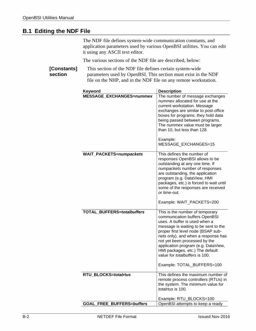
OpenBSI Utilities Manual
B-2 NETDEF File Format Issued Nov-2016
B.1 Editing the NDF File
The NDF file defines system-wide communication constants, and application parameters used by various OpenBSI utilities. You can edit it using any ASCII text editor.
The various sections of the NDF file are described, below:
[Constants] section
This section of the NDF file defines certain system-wide parameters used by OpenBSI. This section must exist in the NDF file on the NHP, and in the NDF file on any remote workstation.
Keyword Description MESSAGE_EXCHANGES=nummex The number of message exchanges
nummex allocated for use at the current workstation. Message exchanges are similar to post-office boxes for programs; they hold data being passed between programs. The nummex value must be larger than 10, but less than 128. Example: MESSAGE_EXCHANGES=15
WAIT_PACKETS=numpackets This defines the number of responses OpenBSI allows to be outstanding at any one time. If numpackets number of responses are outstanding, the application program (e.g. DataView, HMI packages, etc.) is forced to wait until some of the responses are received or time-out. Example: WAIT_PACKETS=200
TOTAL_BUFFERS=totalbuffers
This is the number of temporary communication buffers OpenBSI uses. A buffer is used when a message is waiting to be sent to the proper first level node (BSAP sub-nets only), and when a response has not yet been processed by the application program (e.g. DataView, HMI packages, etc.) The default value for totalbuffers is 100. Example: TOTAL_BUFFERS=100
RTU_BLOCKS=totalrtus This defines the maximum number of remote process controllers (RTUs) in the system. The minimum value for totalrtus is 100. Example: RTU_BLOCKS=100
GOAL_FREE_BUFFERS=buffers OpenBSI attempts to keep a ready

OpenBSI Utilities Manual
Issued Nov-2016 NETDEF File Format B-3
supply of buffers available for general use. If the number of buffers available is less than this value, OpenBSI copies some data into local buffers of the currently running process. The buffers value should be 1/2 of the total buffers or around 20, whichever is smaller. Example: GOAL_FREE_BUFFERS=30
DEF_MESSAGE_TIMEOUT=timeout The time-out interval OpenBSI waits before declaring that any message, including those routed to another workstation, is lost and will never return. You must specify the timeout value in seconds. Example: DEF_MESSAGE_TIMEOUT=60
RTU_RETRIES=retries The number of attempts OpenBSI makes to send a message to a first level RTU (BSAP sub-nets only) before it declares that RTU as “dead” or non-functional. The default value for retries is 4. Example: RTU_RETRIES=4
PATH_ERRORS=errorpath The errorpath string indicates the location of OpenBSI's language-specific error text files. Users who purchase the OpenBSI Development Kit can edit the message text within these files to conform to their own language requirements, e.g. to create error messages in Spanish, French, etc. The file names of “BSSTATUS.TXT” or “BSJOURN.TXT” are appended to this string to find the files. Example: PATH_ERRORS=C:\ProgramData\Bristol\OPENBSI
JOURNAL_FILE =journalpath This journalpath string is the path and file name for the currently active OpenBSI journal file. Example: JOURNAL_FILE=C:\ProgramData\Bristol\ACCOL\JOURNAL.DAT
DELETE_JOURNAL=select If select is non-zero, indicates that the journal file is deleted on OpenBSI

OpenBSI Utilities Manual
B-4 NETDEF File Format Issued Nov-2016
start-up. This helps prevent the journal file from eventually growing to a large size, and consuming excess disk space. Example: DELETE_JOURNAL=0
ACCOL_PATH=acopath The acopath string indicates the directory/folder where the system stores ACCOL files. Example: ACCOL_PATH= C:\ProgramData\Bristol\OPENBSI\ACCOL
IP_PORT=portnumber The UDP portnumber (sometimes known as a socket number) used for communication with RTUs. The system uses it to split message traffic along different “streams”. All PC's or RTU's which are to communicate with each other must have the same portnumber value for IP_PORT. In this sense, it is like a common password which must be known by each node in the network (or sub-network). If no value is entered, NetView assigns a default value for use throughout the network. (Although the term “UDP port” is used, it has no actual relationship with the physical communication ports.) Example: IP_PORT=100
TIMESYNC_PORT=timeportnum The UDP port number used for time synchronization of the RTUs. Any connected PC or RTU which does not have this timeportnum value will be unable to receive time synchronization messages. In a sense, therefore, this value is like a common password which must be known throughout the network. If no value is entered, NetView assigns a default value for use throughout the network. (Although the term “UDP port” is used, it has no actual relationship with the physical communication ports.) Example: TIMESYNC_PORT=101
TIMESYNC_FREQUENCY=frequency Frequency of time synchronization messages to RTUs. You must specify the frequency in seconds. Example: TIMESYNC_FREQUENCY=3600
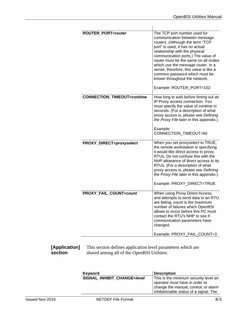
OpenBSI Utilities Manual
Issued Nov-2016 NETDEF File Format B-5
ROUTER_PORT=router The TCP port number used for
communication between message routers. (Although the term “TCP port” is used, it has no actual relationship with the physical communication ports.) The value of router must be the same on all nodes which use the message router. In a sense, therefore, this value is like a common password which must be known throughout the network. Example: ROUTER_PORT=102
CONNECTION_TIMEOUT=contime How long to wait before timing out an IP Proxy access connection. You must specify the value of contime in seconds. (For a description of what proxy access is, please see Defining the Proxy File later in this appendix.) Example: CONNECTION_TIMEOUT=60
PROXY_DIRECT=proxyselect When you set proxyselect to TRUE, the remote workstation is specifying it would like direct access to proxy RTUs. Do not confuse this with the NHP allowance of direct access to its RTUs. (For a description of what proxy access is, please see Defining the Proxy File later in this appendix.) Example: PROXY_DIRECT=TRUE
PROXY_FAIL_COUNT=count When using Proxy Direct Access, and attempts to send data to an RTU are failing, count is the maximum number of failures which OpenBSI allows to occur before this PC must contact the RTU's NHP to see if communication parameters have changed. Example: PROXY_FAIL_COUNT=3
[Application] section
This section defines application level parameters which are shared among all of the OpenBSI Utilities:
Keyword Description SIGNAL_INHIBIT_CHANGE=level This is the minimum security level an
operator must have in order to change the manual, control, or alarm inhibit/enable status of a signal. The

OpenBSI Utilities Manual
B-6 NETDEF File Format Issued Nov-2016
Keyword Description default security level for this is 4.
LIST_RECIPE_CHANGE=level This is the minimum security level an operator must have in order to change a signal list or recipe in DataView. The default security level for this is 3.
SECURITY_SCHEME=choice When choice=0, the password only security scheme is used. When choice=1, the username/password scheme is used. The default is password only.
SIGNAL_DATA_RATE=rate This is the refresh rate (in seconds) at which signal data should be updated on the screen. The default rate is 5.
ARRAY_DATA_RATE=rate This is the refresh rate (in seconds) at which array data should be updated on the screen. The default rate is 30.
COMM_STATS_RATE=rate This is the refresh rate (in seconds) at which communication statistics in the Remote Communication Statistics Tool should be updated on the screen. The default rate is 15.
COMM_RETRIES=retries retries is the number of unsuccessful attempts the Data Collector makes to collect data from an RTU, before declaring an error. If a modem is used, this same number defines the number of modem retries which will be made. The default number of retries is 3.
MODEM_RETRY_INTERVAL=interval In some applications, a pair of ACCOL signals is used to notify that a modem should be turned ON/OFF to allow for data collection. The interval defines the rate (in seconds) at which the Data Collector examines the Modem Confirm signal, to see if it has been turned ON. The default value for this parameter is 1 second.
DATAVIEW_LISTS_PATH=path
This is the directory path DataView uses to store signal searches (.SCH), recipes (.RCP) and DataView Lists (.DVL). The default path is \OPENBSI.
COLLECTOR_CFG_PATH=path This is the directory path used by the

OpenBSI Utilities Manual
Issued Nov-2016 NETDEF File Format B-7
Keyword Description Data Collector and the Data File Conversion utility for storing configuration files such as STATION.CFG and DACONFIG.TXT.
COLLECTOR_DATA_PATH=path This is the directory path where the Data Collector stores its data. This data includes information collected from: signal lists, the archive files, data arrays, and audit trail alarm and event buffers.
WEB_BROWSER_PATH=path This is the directory path where OpenBSI looks for Microsoft® Internet Explorer. This is necessary when configuring ControlWave series controllers.
MASTER_PASSWORD=string DO NOT ATTEMPT TO EDIT THIS STRING. DOING SO WILL MAKE THIS FILE UNREADABLE BY NETVIEW.
B.2 Defining a Proxy File:
Proxy RTU's are controllers (RTU's) which the current OpenBSI workstation may have access to, but only if access has been granted by the Network Host PC (NHP). The workstation does NOT initially know the IP address (or BSAP address) necessary to connect to these RTU's, it only knows the name and address of an NHP, and the RTU node names associated with that NHP.
The proxy file is a file on the OpenBSI workstation which contains the name of an NHP, and its RTU node names. If the workstation requires communication with one of those RTU's it must first contact the NHP and request access. The NHP can grant limited access, by intercepting messages and delivering them indirectly, or it may grant direct access by notifying the workstation to contact the RTU directly via the RTU's IP address (not possible for BSAP RTU's).
The contents of the proxy file are described below:
Keyword Description NETWORK_TYPE = nettype This is the type of sub-network the NHP is
on. This should always be IP.
NAME =nhpname This field defines the host name for this NHP. A maximum of 16 characters are allowed.
IP_PRIMARY =a.b.c.d This field defines the 4 byte Primary IP address of the NHP

OpenBSI Utilities Manual
B-8 NETDEF File Format Issued Nov-2016
Keyword Description
IP_SECONDARY =e.f.g.h This field defines the 4 byte Secondary IP address of the NHP
RTU_x=rtuname These entries define the names of RTU's accessible via this NHP.
Figure B-1 shows a sample proxy file.
NETWORK_TYPE=IP NAME=OFFICE_HQ IP_PRIMARY=123.10.0.1 IP_SECONDARY= RTU_1=ELMSTREET RTU_2=PARKROAD RTU_3=FRONTSTREET RTU_4=SEASIDEDRIVE RTU_5=MAINSTREET RTU_6=CEDARLANE RTU_7=BOULEVARD
Figure B-1. Sample Proxy File
B.3 Using the Off-Line Database Configuration Utility (DBConfig)
The off-line Database Config Utility allows you to perform off-line modifications to existing system structures (NHPs, communication lines, RTUs, networks) in the NETDEF Database Files (*.MDB, *.DSN, *.LDB). The Database Config Utility CANNOT add new structures, or delete existing structures; it only performs modifications.
The off-line Database Config Utility is the recommended method for performing off-line modifications to the NETDEF Database Files. If, instead, you would like to edit the database files directly using a third-party package (such as Microsoft® Access) see Database Tables and Fields later in this appendix.

OpenBSI Utilities Manual
Issued Nov-2016 NETDEF File Format B-9
B.3.1 Starting the Database Config Utility
To start the Database Config Utility, click on Start>Programs>OpenBSI Tools> Common Tools > Off-Line Database Config.
Figure B-2. Off-Line Database Configuration utility
B.3.2 Opening a Set of NETDEF Files for Modification
Once you start the Database Config Utility, you can choose the set of NETDEF files you would like to modify. (The NETDEF files must have been created with OpenBSI Version 3.1 (or newer), older NETDEF files cannot be opened.)
To open the file, click on the icon, shown above, or click File>Open. The Open NetDef File dialog box opens, from which you can select the desired NDF filename.
Caution If NetView is currently running, do not attempt to modify the currently running NETDEF files.
Once you select a file, and click Open, the utility prompts you to provide a username and/or password for access to the NETDEF file. Editing of NETDEF files requires user privileges of either an Engineer or an Administrator.

OpenBSI Utilities Manual
B-10 NETDEF File Format Issued Nov-2016
Figure B-3. Selecting a NETDEF File for Modification
B.3.3 Modifying Your BSAP or IP Network
Once you start the Database Config Utility, you can choose the set
of NETDEF files you would like to modify. (The NETDEF files must have been created with OpenBSI Version 3.1 (or newer), older NETDEF files cannot be opened.) To modify the details of an existing BSAP network or IP network, click on the icon, shown above, or click Modify>Network Record. The Network Record Configuration dialog box opens:
Figure B-4. Network Record Configuration dialog box
Depending upon the type of network (BSAP or IP) not all options are available. For descriptions of the various fields, see below. After you specify all desired changes, click Update to make the actual modifications to the database.
Field Description Network Name Use this list box to select which of your configured
networks you want to modify.
Network Type This field displays the type of network (BSAP or IP) which you selected. This field cannot be edited.
RTU Message An RTU must respond to a program (such as DataView,

OpenBSI Utilities Manual
Issued Nov-2016 NETDEF File Format B-11
Field Description Timeout Netview, etc.) within this number of seconds. If no
response is received, the node is said to have “timed out.” For more information on this parameter, see Network Wizard: Step 2 of 2 in Chapter 6.
[Network Levels] This push button is used for BSAP/EBSAP networks only, and activates the Network Levels dialog box.
This dialog box allows you to specify the maximum number of RTUs which are slaves to a given master node. When finished,
click OK to return to the Network Record Configuration dialog box.
Alarm Destinations
This push button activates the Alarm Destinations dialog box. This dialog box lets you specify the IP addresses of up to four OpenBSI workstations you want to receive alarm reports from the RTUs in this network. Click on OK when finished to return to the Network Record Configuration dialog box.
RBE Destinations This push button activates the RBE Destinations dialog box. This dialog box lets you specify the IP addresses of up to four OpenBSI workstations which you want to receive report by exception (RBE) data from the RTUs in this network. Click OK when finished to return to the Network Record Configuration dialog box.

OpenBSI Utilities Manual
B-12 NETDEF File Format Issued Nov-2016
Field Description Update Click on this push button to save all of the changes to
this network.
B.3.4 Modifying Your BSAP/EBSAP/Local BSAP or IP Communication Line
To modify the details of an existing communication line, click on the icon, shown at left, or click Modify> Line Record. The Line Record Configuration dialog box opens:
Depending upon the type of communication line, not all options are available. For descriptions of the various fields, see below. After you specify all desired changes, click Update to make the actual modifications to the database.
Figure B-5. Line Record Configuration dialog box
The following parameters apply to all types of communication lines:
Field Description Line Name Use this list box to select which of your configured
communication lines you want to modify.
Line Type This field displays the type of communication line which you selected. You cannot edit this field.
The following parameters are for BSAP, EBSAP, and Local BSAP lines only:
Field Description Poll Period For BSAP/EBSAP lines, this is the rate (in seconds) at
which OpenBSI requests data from the top-level RTUs in the network. For Local BSAP lines, this is the rate (in seconds) at which OpenBSI requests data from the currently selected RTU.
Baud Rate Use this list box to specify the rate at which communications occur on this line.
Link Timeout This is the maximum amount of time (in seconds) that OpenBSI waits to receive a response to any one data link transaction. If 0 is entered as the link timeout, the system

OpenBSI Utilities Manual
Issued Nov-2016 NETDEF File Format B-13
Field Description uses a default timeout calculated based on the baud rate of the line.
FPad Chars, BPad Chars
These fields specify the number of null characters to insert at the front end (FPad), or back end (BPad) of a message. Null characters are useful in situations where there may be a momentary delay which could cause the start of a message to be missed, for example, while a radio link is being activated. Null characters are also necessary if you are communicating using a 2-wire RS-485 link, to ensure that DTR is not dropped prematurely. To determine the delay caused by null packing, perform the following calculation:
seconds of delay = number of null characters * 10 baud rate
Dial Checking this box indicates that this is a dial-up line. (Not supported for IP lines.) Click Advanced Dial Parms to modify dialing parameters. For information on these, see Specifying Dial Parameters in Chapter 6.
Modem Check this box if the RTUs on this line require RTS/CTS hand-shaking in order for messages to be sent. The NHP turns on the Request to Send (RTS) control line for the RTU, which must respond to the NHP by turning on the Clear to Send (CTS) control line, at which point, the data can be sent.
The following parameters are for BSAP, EBSAP Lines only:
Field Description Low Slave This value is the lowest local address among all of the
Level 1 RTUs on this communication line. (The local address is determined based on switches, soft switches, or jumpers at the RTU.)
High Slave This value is the highest local address among all of the Level 1 RTUs on this communication line. It CANNOT be less than the value of Low Slave.
The following parameters are for Local BSAP Lines only:
Field Description Local Check this box if this is a Local BSAP Line. (Local BSAP
lines are typically used for one of two things: 1) As a backup line for use when a regular communication line fails; 2) To plug an OpenBSI Workstation in at a lower level of a BSAP network.
Allow Traffic Up By default, a Local BSAP Line communicates only with the RTU to which it is currently connected, and any slave nodes of that RTU. Checking this box allows the Local BSAP Line

OpenBSI Utilities Manual
B-14 NETDEF File Format Issued Nov-2016
Field Description to reach RTUs at higher levels of the network, i.e. the master of the RTU to which you are currently connected.
The following parameters are for IP lines only:
Field Description Ack Timeout This should be set to the maximum amount of time it takes
for a sending node to receive the acknowledgment of a data request (i.e. after sending a message, how long should a node wait to hear that the request reached its destination.) This should be based on the maximum turn-around time between the NHP and any RTU in the address range for this communication line.
Retries This is the number of link level retries. It represents the total number of attempts OpenBSI makes to send a message to an RTU on this line. An attempt is said to have failed if an Ack Timeout occurs.
Range This field specifies (in dotted decimal format) the valid range of IP addresses for this communication line. For more information on this subject, see Chapter 6.
Mask This field specifies (in dotted decimal format) which bits in the binary representation of the corresponding Range field are common to any valid IP address on this communication line.
Write Delay This is the amount of time (in seconds) the system should wait before sending a packet, if the packet has empty space to hold more data. This could occur, for example, if a data request for information about a single signal comes in, but there is additional room in the data packet to hold data for additional signals. If the Write Delay has not expired, the system waits for additional data requests for signal data to come in, and fill up the free space in the packet with responses to those requests. If additional requests do not come in before expiration of the delay, the packet is sent “as is.”
Throttle Delay This delay (specified in seconds) is triggered if the system runs out of buffers. If this occurs, other nodes must wait for the time specified by the delay before sending more messages. This delay allows buffers to be freed up.
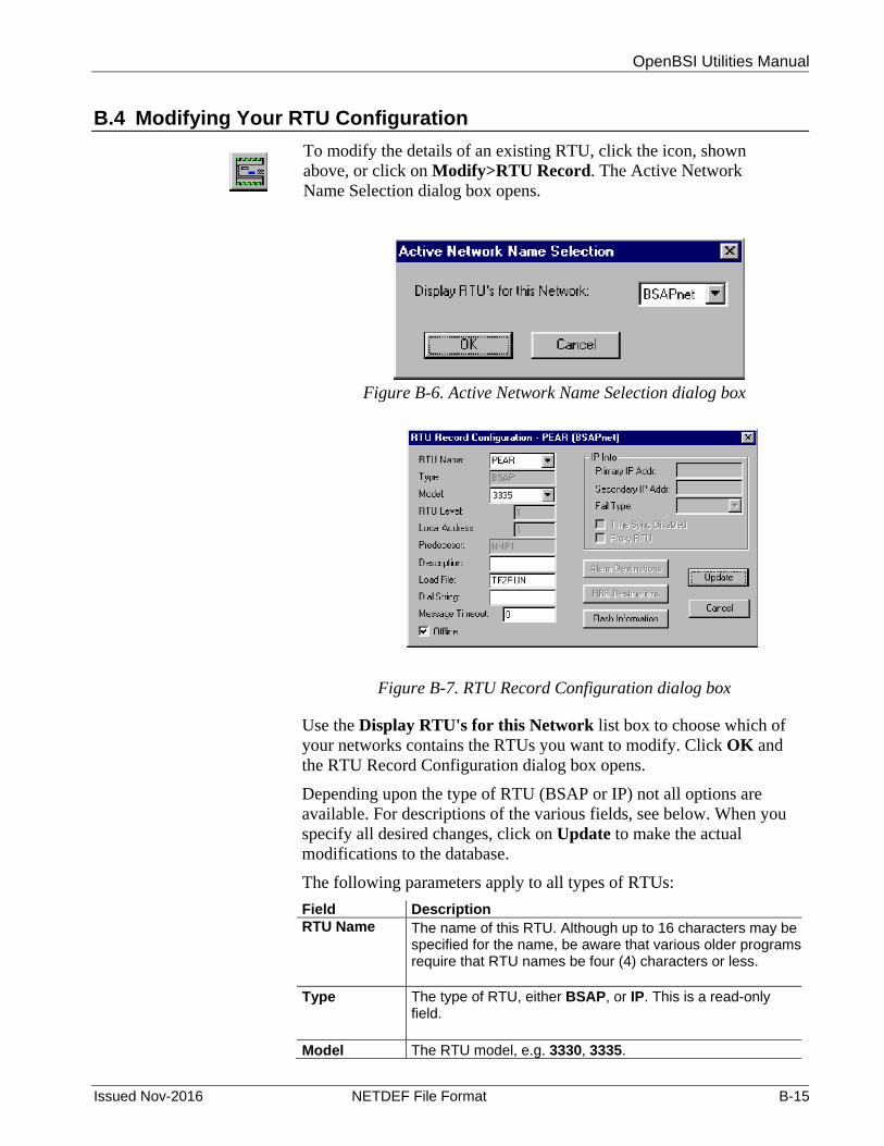
OpenBSI Utilities Manual
Issued Nov-2016 NETDEF File Format B-15
B.4 Modifying Your RTU Configuration
To modify the details of an existing RTU, click the icon, shown above, or click on Modify>RTU Record. The Active Network Name Selection dialog box opens.
Figure B-6. Active Network Name Selection dialog box
Figure B-7. RTU Record Configuration dialog box
Use the Display RTU's for this Network list box to choose which of your networks contains the RTUs you want to modify. Click OK and the RTU Record Configuration dialog box opens.
Depending upon the type of RTU (BSAP or IP) not all options are available. For descriptions of the various fields, see below. When you specify all desired changes, click on Update to make the actual modifications to the database.
The following parameters apply to all types of RTUs:
Field Description RTU Name The name of this RTU. Although up to 16 characters may be
specified for the name, be aware that various older programs require that RTU names be four (4) characters or less.
Type The type of RTU, either BSAP, or IP. This is a read-only field.
Model The RTU model, e.g. 3330, 3335.

OpenBSI Utilities Manual
B-16 NETDEF File Format Issued Nov-2016
Field Description
Local Address This is the BSAP local address of this RTU, which must range from 1 to 127. This is a read-only field.
Description A textual description of this RTU, up to 64 characters in length.
Load File The ACCOL load file name which runs in this RTU.
Dial String The dial string consists of the phone number the OpenBSI workstation sends to an attached modem in order to dial this RTU. The dial string may also include modem. OpenBSI immediately precedes the dial string with the “AT” modem command. Note: Dialing is not yet supported for IP RTUs.
Message Timeout
This value specifies (in seconds) how long to wait before declaring that a message, routed to this RTU, is lost and will never return. If you don’t specify a value, the system uses the default message time-out period for the network.
Offline When checked, turns off communications with this RTU.
Flash Information
This push button activates the RTU Flash Record Configuration dialog box. See Using the RTU Flash Record Configuration Dialog Box later in this appendix.
The following parameters apply to BSAP RTUs ONLY:
Field Description RTU Level This is the network level, which ranges from 1 to 6. This is a
read-only field.
Predecessor Predecessor is the master of this BSAP RTU. This is a read-only field.
The following parameters apply to IP RTUs only:
Field Description Primary IP Addr
The IP address of this RTU, in dotted decimal format. If this RTU has two IP ports, this is the address of the primary port. If this RTU is part of a redundant pair of RTUs, this is the address for the "A" unit of the redundant pair.
Secondary IP
If this RTU has two IP ports, this is the address of the second port. If this RTU is part of a redundant pair of RTUs, this is the address for the "B" unit of the redundant pair.
Fail Type Use this list box to choose either “Primary” or “Symmetric” as the fail type. If you choose “Primary,” OpenBSI always attempts to communicate with this RTU using the Primary IP Address, unless that link fails, in which case, it tries to communicate using the Secondary IP Address. If you choose “Symmetric,” OpenBSI always attempts to use the

OpenBSI Utilities Manual
Issued Nov-2016 NETDEF File Format B-17
Field Description current working communication link (either primary or secondary) and then if that link fails, it fails over to the alternate link. Choose this method if the RTU belongs to a redundant pair.
Time Sync Disabled
If you select this option, time synchronization messages will NOT be sent to this RTU.
Proxy RTU If you select this option, any OpenBSI 3.x workstation granted proxy direct access would be allowed to send messages directly to this RTU.
Alarm Destinations
This push button activates the Alarm Destinations dialog box, discussed earlier in this appendix.
B.4.1 Using the RTU Flash Record Configuration Dialog Box
The RTU Flash Record Configuration dialog box is accessible from the Flash Information push button in the RTU Record Configuration dialog box.
Figure B-8. RTU Flash Record Configuration dialog box
The following entries apply to any RTU supporting FLASH memory:
Field Description Local Addr This is the BSAP local address, which must be an integer
from 1 to 127. The default is 1. NOTE: Even if this RTU will be part of a purely IP network, the local address entered here must match that defined in the RTU to allow for proper routing of alarm and RBE messages.
Def Gateway
This is an IP address of a default gateway. The default gateway is an address to which any messages with destinations which are not directly reachable will be sent (i.e. not in the address range specified via the IP mask for this node.) This address must be entered in dotted decimal format.
EBSAP Group This is the EBSAP group number. If this network does NOT use expanded node addressing, the EBSAP group number should be 0.
IBP Port This is the UDP port number (socket number) used by the Bristol IP driver. It is used to split message traffic along

OpenBSI Utilities Manual
B-18 NETDEF File Format Issued Nov-2016
Field Description different “streams”'. All PC's or RTU's which are to communicate with each other must have the same IBP port number.
NHP 1 This is the primary IP address for this RTU's Network Host PC (NHP). It must be entered in dotted decimal format.
NHP 2 This is a secondary IP address for the same NHP referenced by NHP1 (or the IP address of a redundant backup NHP). It must be entered in dotted decimal format.
Tsync Port This is the UDP port number (socket number) used for time synchronization of the RTU's. All PC's or RTU's must have this value defined, or else they will be unable to receive time sync messages.
Updump Updump should be enabled only if Bristol Application Support or Development personnel are attempting to debug a problem, and need a copy of the unit's internal system memory (memory dump). When this option is selected, and the RTU resets, it will wait for a few seconds for the user to press the reset button again. Rather than enter self-test mode following a crash, updump enable causes a menu to be activated on the attached PC or laptop which allows system RAM to be saved in a disk file.
Port Configuration
This push button calls up the RTU Port Configuration dialog box.
B.4.2 Using the RTU Port Configuration Dialog Box
The RTU Port Configuration dialog box is accessible from the Port Configuration push button of the RTU Flash Record Configuration dialog box.
Figure B-9. RTU Port Configuration dialog box
Field Description Port Name Choose the name of the RTU port from this list box.

OpenBSI Utilities Manual
Issued Nov-2016 NETDEF File Format B-19
Field Description
Type The type of communication protocol which will use this port. Choices are “BSAP”, “EBSAP”, “PPP”, “USER_MODE”, or “UNUSED”.
User Mode This field is only used if “USER_MODE” is chosen for the "Type". It indicates a protocol number which is used to reference internal and custom tables at the RTU, in order to select the proper driver software for this custom data link.
Baud Rate This is the baud rate used by this serial port for BSAP cold downloads. (If IP communication is performed through this port, this is also the baud rate used.) The default baud rate is 9600.
Parity Specifies either ODD, EVEN, or NONE for the parity. The default is NONE. This field is ignored for BSAP or EBSAP communication.
Bits This is the number of bits used in a character. The default is 8. This field is ignored for BSAP or EBSAP communication.
Stop Bits This is the number of stop bits per character. The default is 1. This field is ignored for BSAP or EBSAP communication.
PPP/User Mode Port Config:
IP Address This is the IP address of this serial IP port. This address must be in dotted decimal format, and must be unique.
IP Mask This specifies the range of valid IP address which this RTU can send messages to through this port. It must be entered in dotted decimal format.
Parameter 1 This is a protocol-specific value which may be utilized by a non-standard protocol at RTU initialization. Its value is 4 bytes unsigned, and defaults to 0. (This field is only used for non-standard, customized data links.)
Parameter 2 This is a second protocol-specific value which may be utilized by a non-standard protocol at RTU initialization. Its value is 4 bytes unsigned, and defaults to 0. (This field is only used for non-standard, customized data links.)
Ethernet Port Config:
IP Addr A This is the IP address of the Ethernet Port on the “A” unit of a redundant pair of RTU's, or of the current RTU if it is NOT part of a redundant pair. This address must be in dotted decimal format, and must be unique.
IP Addr B This is the IP address of the Ethernet Port on the “B” unit of a redundant pair of RTU's. This address must be in dotted decimal format, and must be unique. If this RTU is NOT part of a redundant pair, the “B” address may be specified as 0.0.0.0.

OpenBSI Utilities Manual
B-20 NETDEF File Format Issued Nov-2016
Field Description IP Mask This specifies the range of valid IP addresses which this
RTU can send messages to through this port. It must be entered in dotted decimal format.
B.5 Database Tables and Fields
Notes:
We recommend you perform all of your off-line database edits using the Database Config Utility, described earlier, in this appendix. Advanced users or developers may, however, choose to access or edit tables/fields directly using a third-party package such as Microsoft® Access. Exercise care, however, because improper edits to the database could potentially corrupt your NETDEF files, thereby resulting in a loss of system communications.
In the database tables, all IP addresses are stored as large hexadecimal numbers.
B.5.1 “net” table fields Field Description nid Table id of network.
name The sub-network name.
type Type of sub-network defined by this section. Either BSAP(1)
or IP(2).
master Network Master Node for a BSAP sub-network, either an IP defined RTU, or this NHP. The value is an index into the “rtu” table.
levels Maximum number of RTUs per level used in global addressing for each level of the BSAP sub-network. This field is for BSAP sub-networks ONLY. Example Value: 3,5,10
nrt_ver Integer representing the version of the Node Routing Table for this BSAP sub-network.
rtu_tmo The time-out interval to wait before declaring that a message, routed to any RTU on this subnet, has been lost and will never return. If this field is not specified or is 0, the default time-out period is used. The value is specified in seconds.
alrm1 – alrm4 These fields define IP address destinations for alarm messages from this network. Up to four IP addresses can be specified. This field is for IP networks ONLY.

OpenBSI Utilities Manual
Issued Nov-2016 NETDEF File Format B-21
Field Description rbe1 – rbe 4 These fields define IP address destinations for rbe
messages from this network. Up to four IP addresses can be specified. This field is for IP networks ONLY.
B.5.2 “rtu” table fields Field Description rid Table id of RTU.
nid Table id of network this RTU belongs to.
name The RTU name.
type Type of sub-network this RTU belongs to. Either BSAP(1) or
IP(2).
model This field defines the RTU type. {NONE=0, 3305=1, 3308=2, 3310=3, 3330=4, 3335=5, 3508=6, 3530=7, VIRTUAL=8, 9=ControlWave, 10=CWave_LP, 11=CWave_RIO, 12=CWave_Micro, 13=CWave_EFM, 14=CWave_GFC, 15=CWave_XFC, 16=CW_10, 17=CW_30, 18=3808 and 4088B, 19=CWave_Exp }
descr A textual description of the RTU. A maximum of 64 alpha-numeric characters are allowed.
load This field defines the ACCOL load file base name for the RTU. This field can be up to 16 alpha-numeric characters.
lvl Level of the BSAP sub-network this RTU in on. “Lvl” can range from 1 to 6. This field is for BSAP RTU's ONLY.
local Local Address of the RTU. “local” can range from 1 to 127. This field is for BSAP RTU's ONLY.
pred Predecessor node (or Master) this RTU is attached to. This field is for BSAP RTU's ONLY. “rid” of RTU.
dial_str
Phone number to use if this RTU is on a dial-up line. Currently available for BSAP RTU's ONLY.
offline If non-zero, this RTU is considered off-line and no communication is attempted.
rtu_tmo
The time-out interval to wait before declaring that a message, routed to this RTU, has been lost and will never return. If this field is not specified, the default time-out period is used. The value of rtu_tm is specified in seconds.
ip_prim
This field defines the 4 byte Primary IP address of this RTU.
ip_sec This field defines the 4 byte Secondary IP address of this RTU.
fail_type Fallback handling method. Primary(1) or Symmetric(2).

OpenBSI Utilities Manual
B-22 NETDEF File Format Issued Nov-2016
Field Description Primary will always try the primary link first and in the failure case will fallback to the secondary. Symmetric will continue to use the current working link (primary or secondary) until a failure occurs, in which case it will fall back to the alternate. This field is for IP RTU's ONLY.
time_sync Disables time synchronization messages for this RTU. When set to TRUE, messages are disabled; when set to FALSE, they are enabled. This field is for IP RTU's ONLY.
proxy When set to TRUE, direct access is allowed to this RTU; when set to FALSE, direct access to this RTU is denied. This field is for IP RTU's ONLY.
alrm1 – alrm4
These fields define IP address destinations for alarm messages from this RTU. Up to four IP addresses can be specified. This field is for IP RTUs ONLY.
rbe1 – rbe4
These fields define IP address destinations for rbe messages from this RTU. Up to four IP addresses can be specified. This field is for IP RTUs ONLY.
proxy_tmo Message timeout for RTUs that are remote proxy RTUs.
web_page Name of startup web page for this RTU.
B.5.3 “flash” table fields
The next several entries are constants which are programmed into FLASH memory of the RTU:
Field Description rid Table id of RTU in “rtu” table.
updump If set non-zero, RTU is in diagnostic mode, and can
UPDUMP its memory (equivalent to Switch 8 on address switch bank).
laddr RTU Local address used for BSAP communications. The default for this field is pulled from the LOCAL_ADDRESS parameter. “laddr” can range from 1 to 127.
group Group number for EBSAP (expanded node addressing) communications. Default of zero indicates standard BSAP.
nhp_a IP address for the primary PC which is the “master” for this RTU. Being “master” indicates that that PC is responsible for sending time synchs and alarm destination information to this RTU.
nhp_b Secondary IP address for “master” PC. (Can also be a second PC).
def_gw IP address for the default gateway. The default gateway is a computer to which packets are sent when the address and

OpenBSI Utilities Manual
Issued Nov-2016 NETDEF File Format B-23
Field Description sub-net masks for the ports do not indicate where a packet is to be sent. This computer then forwards the packet to its destination.
ibp_port UDP port to be used for IBP (standard OpenBSI) communications to this RTU. This value must be the same as the OpenBSI IBP port on any PC or RTU which is communicating to this RTU via IP.
ts_port UDP port to be used for time synchs to this RTU. This value must be the same as the Time Synch Port on any NHP for this RTU. Default value is pulled from NDF file.
enet_ipaddra IP address for the Ethernet port on redundant unit “A” (or if the unit is not redundant, the current RTU). The IP addresses for all nodes must be unique (this includes redundant backup nodes). If this value is zero, the Ethernet port is not used for IP communications.
enet_ipaddb If the unit is redundant, the IP address for the “B” unit. This address must be different than unit “A” and be unique in the network.
ipmask Subnet mask to indicate which network sub-section is reachable out the Ethernet port.

OpenBSI Utilities Manual
B-24 NETDEF File Format Issued Nov-2016
B.5.4 “port” table fields
For the next series of parameters, there are a series of groups, one for each port in the RTU. Within each port, the parameters are prefixed by the port name: (A, B, C, D, BIP1, BIP2, G, H, I, J). These parameters are set (in FLASH memory) to define the cold download rates and protocol for each port. In addition, if the communication protocol used is IP, these parameters are also used by the running system. If particular parameters are omitted, defaults will be used. If the entire section is omitted, the default is for a BSAP port at 9600 baud.
Field Description rid Table id of RTU in “rtu” table.
port RTU port name.
baud Serial communications rate for port. {300=2, 600=3,
1200=4, 2400=5, 4800=6, 9600=7, 19200=8, 38400=9, 187500=10, 1MEG=11, RASCL=12}
parity Parity bit used. {none=0, odd=1, even=3}
bits Number of data bits. {6bits=128, 7bits=64, 8bits=192}
stop_bits
Number of stop bits for serial communications. {1bit=4, 1and ½bits=8, 2bits=12}
type Indicates the usage for the port. {Unused=0, BSAP=1, EBSAP=2, User_mode=3, PPP=4}
user_mode For IP communications, the protocol number used (if the protocol number is not in the _TYPE list). This allows custom MAC / Data-link layers to be defined.
ip_addr
For IP communications, the IP address assigned to the port.
ip_mask For IP communications, the sub-net mask of addresses which indicates those addresses reachable out this port.
param1
Protocol specific optional parameter.
param2 Protocol specific optional parameter.

OpenBSI Utilities Manual
Issued Nov-2016 NETDEF File Format B-25
B.5.5 “line” table fields Field Description lid Table id of comm line.
name Communication line name.
type Type of communication line defined by this section. “Type”
must be either BSAP(1), IP(2), EBSAP(3) or Local Connect(4).
slaves Defines the high and low slave addresses that are serviced by this communications port. This field does NOT apply to IP communication lines. (Low slave in low order word, High slave in high order word)
local Unused.
dial If non-zero, indicates this communications port uses a modem and dials the RTU to make a connection. This field does NOT apply to IP communication lines.
modem If non-zero, RTS/CTS keying will be used. (modem control). This field does NOT apply to IP communication lines.
poll_per
This field defines how often top level nodes are polled for data. “poll_per” must be specified in milliseconds. NOTE: This field only applies for BSAP or EBSAP line types.
link_tmo This field defines the amount of time to wait before receiving a response to any one data link transaction. “Link_tmo” must be specified in milliseconds. This field does NOT apply to IP communication lines. If 0 is entered for “Link_tmo”, the line will use a default based on the selected baud rate.
baud Rate at which communications is to proceed through this serial port. This field does NOT apply to Ethernet IP communication lines. {300=1, 1200=2, 2400=3, 4800= 4, 9600=5, 19200=6, 38400=7}
padding The number of pad characters at the start & end of a message. Used to help debug with RTS/CTS control of modems & radios or if you are using 2-wire RS-485. This field does NOT apply to IP communication lines. (Front pad in low order word and back pad in high order word)
ip_range
The common portion of all IP addresses on this communication line, with uncommon portions entered as 0. This field applies to IP communication lines ONLY.
ip_mask The sub-net mask associated with the IP_RANGE. This field applies to IP communication lines ONLY.
ack_tmo This should be set to the maximum amount of time it takes for the acknowledgment of a data request to be received by

OpenBSI Utilities Manual
B-26 NETDEF File Format Issued Nov-2016
Field Description the sending node (i.e. after sending a message, how long should a node wait to hear that the request reached its destination) This should be set based on the maximum turn-around time between any two points within this communication line. This field applies to IP communication lines ONLY.
Retries This is the total number of attempts made to send a message. An attempt is said to have failed if an ACK_TIMEOUT occurs.
write_delay The WRITE_DELAY is the amount of time the system should wait before sending a packet, if the packet has empty space to hold more data. This could occur, for example, if a data request for information about a single signal came in, but there was additional room in the data packet to hold data for additional signals. If the WRITE_DELAY has not expired, the system will wait for additional data requests for signal data to come in, and fill up the free space in the packet with responses to those requests. If additional requests don't come in before expiration of the write_delay, then the packet is sent, “as is”. This field applies to IP communication lines ONLY. write_delay must be entered in milliseconds.
throt_delay The throttle delay field is triggered by the system running out of buffers. If this occurs, other nodes must wait for the time specified by the throt_delay before sending more messages. This delay allows buffers to be freed up. This field applies to IP communication lines ONLY. throt_delay must be entered in milliseconds.
init_str This field defines the string the driver will send to initialize the modem. This field does NOT apply to IP communication lines.
dial_retries Defines the number of times the driver will attempt to connect to the RTU. This field does NOT apply to IP communication lines.
dial_tmo Defines the amount of time to wait for the connection to the RT U, before declaring this dial attempt a failure. This field does NOT apply to IP communication lines.
hangup_str1 Defines the first string to send to start the hang-up procedure. This field does NOT apply to IP communication lines.
hangup_str2 Defines the second string to send in the hang-up procedure. This field does NOT apply to IP communication lines.
hangup_retries
Defines the number of times the driver will attempt to hang-up the modem. This field does NOT apply to IP communication lines.
hangup_tmo This field defines the amount of time to wait for the modem to properly hang-up, before declaring this hang-up attempt a failure. This field does NOT apply to IP communication lines.

OpenBSI Utilities Manual
Issued Nov-2016 NETDEF File Format B-27
Field Description
hangup_delay The field defines the amount of time to wait between sending the hang-up strings. This field does NOT apply to IP communication lines.
nodata_tmo This field defines the amount of time with no communication traffic, the driver will wait before hanging up a connected dial line. This field does NOT apply to IP communication lines.
dtr If non-zero, the field tells the driver to use DTR in the operation of the modem. This field does NOT apply to IP communication lines.
local_node RTU table index of RTU line is locally connected to.
local_line If non-zero indicates this line is connected locally to an RTU.
B.5.6 “proxy” table fields Field Description pxid Table index of proxy file.
name Filename of the proxy info.
B.5.7 “seq” table fields
This table contains the next available index for each table, along with a database version.

This page is intentionally left blank

OpenBSI Utilities Manual
Issued Nov-2016 Keyboard Shortcuts C-1
Appendix C – Keyboard Shortcuts
OpenBSI allows you to access system functions by pointing and clicking with the mouse on menu bar and pull down menu items, or by clicking on icons. You can also access several OpenBSI features using keyboard shortcuts which mimic the point and click operations. These are described in the tables which follow.
In addition to the sequences shown, you can also activate most menu selections by a single character keystroke (shown underlined in the menu bar or pull down menu).
C.1 NetView
Menu Bar / Pull Down Menu Sequence
Equivalent Keyboard Sequence
Function
File >New... Ctrl-N Create new set of NETDEF files
File >Open... Ctrl-O Open an existing set of NETDEF files
File>Save Ctrl-S Save the current NETDEF files
File>Print Ctrl-P Print Edit>Undo Ctrl-Z Undo last action
(limited to certain types of actions)
F1 Call up on-line help
C.2 DataView
Menu Bar/Pull Down Menu Sequence
Equivalent Keyboard Sequence
Function
File>Save Ctrl-S Save the current file File>New Ctrl-N Open a new file File>Open Ctrl-O Open an existing file Format>Properties Alt-Enter Re-call the DataView dialog box
to change properties of window. Edit>Insert Ins Insert a line into the current list Edit>Delete Del Delete the currently selected
item File>Copy to Clipboard
Ctrl-C Copy the textual contents of the window to the Clipboard
File>Print Ctrl-P Print the text of this window on the printer
Recipe>Write to RTU
Ctrl-W Write contents of recipe to Network 3000 controller
Recipe>Read From RTU
Ctrl-R Read current values from Network 3000 controller into recipe window
F1 Call up on-line help

OpenBSI Utilities Manual
C-2 Keyboard Shortcuts Issued Nov-2016
C.3 Downloader
Menu Bar / Pull Down Menu Sequence
Equivalent Keyboard Sequence
Function
File>Single Node Ctrl-N Download a single Network 3000 node
File>Open List Ctrl-O Download a group of Network 3000 nodes based on RDL file
F1 Call up on-line help
C.4 Remote Communication Statistics Tool
Menu Bar / Pull Down Menu Sequence
Equivalent Keyboard Sequence
Function
Statistics>Copy to Clipboard
Ctrl-C Copy textual contents of window to Clipboard
Statistics>Print Ctrl-P Print textual contents of window on printer
F1 Call up on-line help
C.5 LocalView
Menu Bar / Pull Down Menu Sequence
Equivalent Keyboard Sequence
Function
File>New Ctrl-N Open a new View Mode File (*.LVG)
File>Open Ctrl-O Open an existing View Mode File (*.LVG)
File>Save Ctrl-S Save the current LVG File. F1 Call up on-line help

OpenBSI Utilities Manual
Issued Nov-2016 Modem and Radio Configuration Tips D-1
Appendix D – Modem and Radio Configuration Tips
D.1 Configuring the Workstation to Dial-up BSAP-capable Controllers
You can configure OpenBSI to allow communication with ControlWave or Network 3000 controllers via an attached modem. When the OpenBSI Workstation needs to communicate with a controller, it notifies the modem to dial-up the controller; once the connection is successfully made, it sends data between the workstation and the controller.
Note: Instructions for setting up the modem connected to the workstation, as well as the modems used by the ControlWave or Network 3000-series controllers are beyond the scope of this manual. See the documentation accompanying your modem for details.
D.2 Guidelines for Configuring Modems to Work with the Controllers
OpenBSI can send an initialization string to the modem. (See “Specifying Dialing Parameters” in Chapter 6.)
OpenBSI’s RTU Wizard also allows you to specify a dial string. (This is also discussed in Chapter 6, as part of BSAP RTU configuration.) You should include a “DT” (tone dialing) or “DP” (pulse dialing) modem command in the dial string.
You must perform any other configuration of the modem(s) using whatever modem configuration software is provided with the modem, or if applicable, via switch settings on the modem.
Table D-1 shows how modem characteristics should be set when connected to an OpenBSI workstation.
The first column describes what modem settings are required.
The second column shows corresponding initialization codes which would be included in the initialization string for a US Robotics modem. If you are starting with a modem which is at its factory default settings, the E1, &C1 and &D2 codes shown in the table are unnecessary.
If you have a different type of modem, use the equivalent initialization code from the manual accompanying that particular modem; not the code shown here. If you still cannot successfully set up your modem, refer to the troubleshooting tips later in this section.

OpenBSI Utilities Manual
D-2 Modem and Radio Configuration Tips Issued Nov-2016
Table D-1. Setting up a Modem to Work with OpenBSI
A modem connected to an OpenBSI Workstation must have the following settings:
Corresponding US Robotics Code:
Turn ON local echo of codes. E1 Note: E1 is a factory default
Disable ARQ result codes. &A0 Set modem’s serial port rate to variable; to follow the connection rate.
&B0
Set Carrier Detect (CD) to normal operation. &C1 Note: &C1 is a factory default
Set Data Terminal Ready (DTR) to normal. &D2 Note: &D2 is a factory default
Disable transmit data (TD) Flow Control. &H0 Disable data compression. &K0 Disable error control. Note: This setting is NOT required if you have an identically configured modem at the RTU end.
&M0
Ignore RTS for receive data (RD). &R1
D.3 Troubleshooting Tips for Modem Problems
Table D-2 shows a list of possible modem configuration problems and suggested remedies.
Table D-2. Modem Troubleshooting
Problem: Suggested Remedy: For an internal modem, there is no communication at all.
If DTR is ON, check to see that the dial string is a correct, valid, phone number.
For an external modem, there is no RD (receive data), and no dialing occurs.
Check to see that the dial string is a correct, valid, phone number.
Check to see that the carrier detect setting is consistent with the carrier detect line, and that the carrier detect line is properly configured.
The modem dials, but does not connect.
Check to see that the dial string is a correct, valid, phone number.
Check to see that the carrier detect setting is consistent with the carrier detect line, and that the carrier detect line is properly configured.
Check the baud rate and connection settings on both modems.
For an external modem, check the wiring of the carrier detect line to the PC.
The modem connects, but does not communicate.
Check the baud rate and connection settings on both modems.
Check the baud rate in OpenBSI, and on the controller’s port.
Verify that flow control is disabled.

OpenBSI Utilities Manual
Issued Nov-2016 Modem and Radio Configuration Tips D-3
Problem: Suggested Remedy: Verify that the controller’s address is correctly
specified in OpenBSI.
D.3.1 OpenBSI Trouble-shooting Tip for Using RTS/CTS with Radios
If you use RTS/CTS with radios, and encounter a problem where the OpenBSI workstation can transmit, but RTUs are unable to respond, it could be related to PC port configuration in Windows which results in messages being truncated.
If this problem occurs follow these steps:
1. Click Start> Settings>Control Panel to call up the Windows control panel.
2. Double-click the System icon. The System Properties dialog box opens.
3. From the Hardware tab, click the Device Manager button:
Figure D-1. Windows System Properties dialog box
Click here

OpenBSI Utilities Manual
D-4 Modem and Radio Configuration Tips Issued Nov-2016
4. Click on the plus sign “+” next to the “Ports (COM & LPT)” selection. This displays a list of ports.
Figure D-2. List of Ports in Device Manager
5. Right-click once on the port used for OpenBSI communications (typically COM1 or COM2), and choose Properties from the pop-up menu.
6. The Communication Port Properties dialog box opens; click the Port Settings tab, then click the Advanced push button to call up the Advanced Port Settings dialog box.
Figure D-3. Communication Port Properties dialog box
Click here

OpenBSI Utilities Manual
Issued Nov-2016 Modem and Radio Configuration Tips D-5
7. In the Advanced Port Settings dialog box, drag the Transmit Buffer slide bar to the low end of its range, and click OK.
Figure D-4. Editing the Advanced Settings for the Port
8. Then choose OK in the Communication Port Properties dialog box, and exit the device manager and control panel to save the settings.
9. Reboot your PC for the new settings to take effect.
Drag the Transmit Buffer slide bar to the low end of the range.

This page is intentionally left blank

OpenBSI Utilities Manual
Issued Nov-2016 Initialization Files E-1
Appendix E – Initialization Files
Beginning with OpenBSI 5.7, OpenBSI includes a configuration tool for editing many of the initialization files.
To access this tool, click on: Start > Programs > OpenBSI Tools > Common Tools > Advanced Configuration.
Note: If there is no asterisk “*” next to the parameter on screen, you must re-start OpenBSI in order for the change to take effect.
E.1 Application Startup/Restart Page
OpenBSI can start applications and services automatically. This is configured on the Application Startup/Restart tab.
Figure E-1. Advanced Configuration – Application Startup / Restart
E.1.1 Application Startup from NetView
It is possible to have NetView start various applications and Windows services. These parameters are stored in the NETVIEW.INI file.

OpenBSI Utilities Manual
E-2 Initialization Files Issued Nov-2016
Field Description Applications A comma delimited list of applications to be started from
NetView. Example: dview, stats
Services A comma delimited list of Windows services to be started from NetView. Example: bservice
E.1.2 Application Startup from BSAUTO / OBSIService
If you configure the BSAUTO or OBSIService feature to automatically start OpenBSI communications you can also configure other programs to start automatically. In addition, you can re-start particular programs that are registered with an OpenBSI message exchange. These parameters are stored in the USERAPPS.INI file.
Note: The choice of BSAUTO or OBSIService depends on your operating system. See Chapter 2 for more information.
Field Description Applications A list of applications to be started. The syntax for specifying
the application requires two separate lines: Appn=path_and_filename Shown=show where
n is a number identifying the entry. These must be consecutive ascending numbers. The first number must be 1.
path_and_filename identifies the location and
executable name of the application to be started
show is either “1” if the application is to be
visible in a window or “0” if the window holding the application is to be minimized.
Click Add then type in the text for the Appn line via the Add/Modify dialog box, and click OK. Then click on Add again to add the Shown line via the same method. To change an existing entry, select it and click Modify. To remove an entry, click on it, and then click Delete.

OpenBSI Utilities Manual
Issued Nov-2016 Initialization Files E-3
` Some sample application entries would be:
App1=C:\”Program Files”\Bristol\OPENBSI\dataview.exe
Show1=1
App2=C:\”Program Files”\Bristol\OPENBSI\stats.exe
Show2=0
E.1.3 Applications to Restart on Failure
OpenBSI can optionally restart applications that have failed. The application to be restarted must be associated with a particular OpenBSI message exchange. These parameters are stored in the USERAPPS.INI file. Changes to these parameters occur immediately, and do not require a re-start of OpenBSI.
Field Description Applications These entries must be entered in the following format:
mex_name=command_line_startup, interval where: mex_name is the name of a message exchange. The
name of particular message exchanges may be obtained via the “Mex Summary” tab of the Monitor Window in NetView. Standard message exchanges include the following:
mex_name Program HARVEST OpenBSI Harvester BSICNVR Data File Conversion Utility MSGRTR OpenBSI Message Router BSIBSAP BSAP communications driver IPDRIVE Bristol IP com. driver
command_line_startup
is a command line argument for restarting the program associated with the specified message exchange. Note: The \openbsi portion of the path need not be entered. The “DRIVER” command line startup entry is special for these communication drivers, and must be entered exactly as shown. You can include restart command line arguments for any program associated with a message exchange.

OpenBSI Utilities Manual
E-4 Initialization Files Issued Nov-2016
command_line_startup OpenBSI program harvester.exe OpenBSI Harvester bsicnvrt.exe Data File Converter rtrservc.exe BSI Message Router DRIVER BSAP com driver DRIVER Bristol IP com driver
interval is a period of time, in milliseconds, that OpenBSI
will wait for the application named by mex_name to re-start itself before forcing a command line startup,
Some sample entries appear, below: HARVEST=harvester.exe, 1000 BSICNVR=bsicnvrt.exe, 1000 MSGRTR=rtrservc.exe, 1000 BSIBSAP=DRIVER, 1000 IPDRIVE=DRIVER, 1000
E.2 Applications Page
The Applications tab sets parameters for certain OpenBSI programs.
Figure E-2 Advanced Configuration – Applications

OpenBSI Utilities Manual
Issued Nov-2016 Initialization Files E-5
E.2.1 OpenBSI Applications that connect to OpenBSI
OpenBSI Utilities such as DataView, the Alarm Router, the Downloader, etc. require the OpenBSI communications driver to be running in order for them to work. These parameters govern how these applications will try to connect to the OpenBSI driver. Most of these entries are stored in the BSBSAP.INI file.
Field Description Number of times to try to connect to OpenBSI
Shows the number of times the utility will try to connect to the OpenBSI driver.
Delay between connection tries
Specifies the period of time (in seconds) between each attempt to connect to OpenBSI. This period of time between attempts causes DataView and other such utilities to wait before declaring an error and shutting down if the OpenBSI communications driver is NOT running due to NetView or LocalView not having been started.
Number of message tries before marking a connected application as dead
Specifies how many times OpenBSI should check to see that a process connected to it is still active. Each count takes one minute. The default is 2 (2 minutes.)
E.2.2 NetView
These parameters define aspects of NetView operation.
Field Description Start NetView in Minimized Mode
Check this box if you want NetView to start minimized. This entry is stored in the NETVIEW.INI file.
Maximum size of journal file This defines the maximum number of entries which can be stored in the currently active journal file. When this number is exceeded, this file is renamed with a *.BAK file extension, and a new empty journal file will be created. NOTE: When this renaming occurs, any previous *.BAK journal file in that directory will be overwritten, therefore, it is the user’s responsibility to remove these files to a different location, if they are to be saved for future reference. This limitation is intended to prevent journal files from consuming too much disk space. This entry is stored in the BSBSAP.INI file.

OpenBSI Utilities Manual
E-6 Initialization Files Issued Nov-2016
E.2.3 1131 Applications Field Description Add 1131 Configuration name to project’s “pro” file name and to project name within the translation ini file
If your ControlWave project includes more than one configuration / resource, for example one for ControlWave and one for ControlWave Micro, and you want to distinguish between the two configurations/resources, check this box to add the configuration and resource name to the PRO files and to project file name references in the translation INI file. (Requires OpenBSI 5.8 Service Pack 1 or newer.) Note: The 1131 Downloader, ControlWave Designer’s Transfer Download Files utility, TechView’s TRANSLATION.INI file, the Signal Extractor, and the @GV._CW_LOAD_STR system variable all use only the first eleven characters to distinguish between project file names. If you choose this option to include the configuration and resource name in the *.PRO filename, make sure they are short enough to fit within the eleven character restriction or else there will be conflicts within filenames.
E.3 Backup Lines
These parameters are associated with backup communication lines. These parameters are stored in the BSBSAP.INI file.

OpenBSI Utilities Manual
Issued Nov-2016 Initialization Files E-7
Figure E-3. Advanced Configuration – Backup Lines
Field Description Switching Choose Backup Line in Round Robin Mode
This specifies how backup lines are chosen. If unchecked, the first free backup line will always be used. If checked, a round-robin method will be used in which OpenBSI chooses the backup line based on a sequential process.
Time to wait before switching from backup to primary
This helps define a period of time to wait before actually switching from the backup line, back to the primary line, to ensure that the primary line is truly stable. The number entered here is multiplied by the poll period to define the waiting time.
Do not initialize statistics on line switch
When checked, prevents communication line statistics from being reset when switching backup lines. When not checked, statistics are reset when lines are switched.

OpenBSI Utilities Manual
E-8 Initialization Files Issued Nov-2016
Line Start Check How often to check for successful started Backup Lines
When OpenBSI starts up, it spends some pre-defined number of minutes checking to see if backup lines have started successfully. If a particular line hasn’t started, attempts will be made to start it This entry defines how frequently, within that period of time, this check for backup lines should occur. The default is 10 seconds. If no value is entered, no checking will occur.
Time interval to check for successful started Backup Lines
This entry defines a period of time (in minutes) at OpenBSI startup, during which checks will be made to see if backup lines have started successfully. If not specified a default value of 1 minute is used.
Modem Check Check modems before use If checked, OpenBSI checks the status of a
modem before it uses that modem for a backup line. If the check fails, OpenBSI reports an error in the OpenBSI journal file. (OpenBSI 5.8 or newer.)
Number of extra modems to check before declaring failure
This specifies that if a backup line is to be chosen, then check to see that its modem is functioning; if the modem isn’t functioning, proceed to the next backup line/modem, and check it, etc., until this number of modems has been checked. If no value is entered here, OpenBSI will continue to check modems until it finds a working one.
Time to wait for Modem Response
specifies how long (in milliseconds) the OpenBSI communications driver will wait for a response during the modem check, before declaring that a modem is not functioning. This time should be specified in msec and generally should be kept low to avoid delays in proceeding to the next modem, if a modem has truly failed. If this item is not in the file, the driver will select a timeout value based on the configured baud rate, for example, at 9600 baud, the timeout would be 3000 milliseconds (3 seconds).
Pseudo Line Name specifies the name of a BSAP Primary Pseudo Communication Line. The pseudo line is NOT actually used for communications, but is used as a place holder for RTUs which will communicate only through dial lines.

OpenBSI Utilities Manual
Issued Nov-2016 Initialization Files E-9
E.4 BSAP Communications Page
These entries define how BSAP ports communicate. These parameters are stored in the BSBSAP.INI file.
Figure E-4. Advanced Configuration –BSAP Communications
Field Description Communications
VSAT Delay after sending an ack to an RTU data message (msec)
This is the amount of time (in milliseconds) OpenBSI waits after sending an ACK to a message from an RTU.
Time interval between NRT retries after failure: (number of link tmo periods)
If no acknowledgement to the first Node Routing Table (NRT)/Time Sync message is received, addition NRT/TS messages are sent at a default interval of 3 seconds. To extend this interval, enter a multiplier in this field. If 1 is the multiplier, the interval is 3 seconds, if 2, the interval is 6

OpenBSI Utilities Manual
E-10 Initialization Files Issued Nov-2016
Field Description seconds, etc.
Number of message sent before issues a poll
This is the number of messages allowed to be sent through this port before issuing a poll message to the RTU.
Reset port when no messages have been received in a link tmo period
When checked, if no response messages have been received and the link timeout has expired, the port will be reset. The only time this should be left unchecked is in certain very specific situations, such as problems with backup lines.
Set DTR line to high (1) When checked, DTR is raised for this port (turned ON). When unchecked, DTR for this port is set low (turned OFF).
Disable sending of Time Sync message
When checked, the OpenBSI Workstation will not send a time synchronization message through its BSAP ports out to the RTUs. (Requires OpenBSI 5.8 Service Pack 1 or newer.)
Misc Generate Off Line Alarms for first level nodes
By default, if communication is lost with a first-level BSAP node, an alarm message called COMM.STATUS will appear in Alarm Router to report the loss of communications. In certain systems which use periodic dial-up or radios, these alarms could be bothersome, since the loss of communications would be considered normal. In those cases, you can disable these alarms by un-checking this entry.
Use UTC when Time Synching
If you want time synching to be with Universal Time (UTC), check this box.
Port Arbitrator: Time to wait for port to be available before declaring a failure (secs)
If using the Port Arbitrator, this is the number of seconds the BSAP driver will wait for a port to be released, before declaring a failure.
Dial Poll all RTUs with same dial number on connection
If checked, and an RTU is connected after a dial, the driver checks for other RTUs that have the same dial-up number and starts polling them as well.
Delay in sending first NRT message on connections (secs)
When a dial attempt succeeds, and carrier detect (CD) is seen, a Node Routing Table (NRT) / Time Sync message is sent. This parameter defines a delay (in seconds) between when carrier detect is seen, and the actual NRT/Time Sync is transmitted.
Debug Enable writing to DLM File When checked, enables the Data Line Monitor feature. This
feature causes a log of communication messages for a BSAP port at the PC to be saved in a file. Note: This can be changed without re-starting OpenBSI.
Ports This field defines the name of the output file of the Data Line Monitor for a given port. Entries must be in the format portname = filename Click Add to add a new entry to the list via the Add/Modify dialog box. To change an existing entry, select it and click Modify. To remove an entry, click on it, and then click Delete. Some sample entries would be:

OpenBSI Utilities Manual
Issued Nov-2016 Initialization Files E-11
Field Description Com1=c:\ProgramData\Bristol\OpenBSI\accol\com1msgs.log
Com2=c:\msgs2.log
E.5 Harvester
These parameters govern the operation of the OpenBSI Harvester utility, and are stored in the Harvester.INI file. Full information on the Harvester is included in the OpenBSI Harvester Manual (document# D5120).
Figure E-5. Advanced Configuration – Harvester
Field Description Refresh and Other Timers
How often to refresh the Configuration Window
This specifies the rate (in milliseconds) at which the configuration pane on the right hand top of the window is updated.
How often to refresh the Monitor Window
This specifies the default rate (in milliseconds) at which the monitor pane of the window is updated.
How often to refresh the RTU Tree Window
This specifies the default rate (in milliseconds). at which the tree of
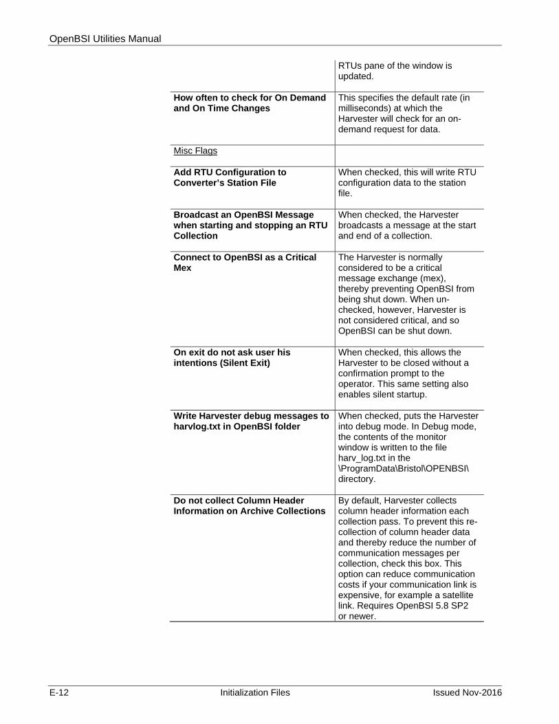
OpenBSI Utilities Manual
E-12 Initialization Files Issued Nov-2016
RTUs pane of the window is updated.
How often to check for On Demand and On Time Changes
This specifies the default rate (in milliseconds) at which the Harvester will check for an on-demand request for data.
Misc Flags
Add RTU Configuration to Converter’s Station File
When checked, this will write RTU configuration data to the station file.
Broadcast an OpenBSI Message when starting and stopping an RTU Collection
When checked, the Harvester broadcasts a message at the start and end of a collection.
Connect to OpenBSI as a Critical Mex
The Harvester is normally considered to be a critical message exchange (mex), thereby preventing OpenBSI from being shut down. When un-checked, however, Harvester is not considered critical, and so OpenBSI can be shut down.
On exit do not ask user his intentions (Silent Exit)
When checked, this allows the Harvester to be closed without a confirmation prompt to the operator. This same setting also enables silent startup.
Write Harvester debug messages to harvlog.txt in OpenBSI folder
When checked, puts the Harvester into debug mode. In Debug mode, the contents of the monitor window is written to the file harv_log.txt in the \ProgramData\Bristol\OPENBSI\ directory.
Do not collect Column Header Information on Archive Collections
By default, Harvester collects column header information each collection pass. To prevent this re-collection of column header data and thereby reduce the number of communication messages per collection, check this box. This option can reduce communication costs if your communication link is expensive, for example a satellite link. Requires OpenBSI 5.8 SP2 or newer.

OpenBSI Utilities Manual
Issued Nov-2016 Initialization Files E-13
E.6 IP Communications
These parameters affect the operation of OpenBSI IP ports. These parameters are stored in the BSIPDRV.INI file.
Figure E-6. Advanced Configuration –IP Communications
Field Description Debug Enable Writing of debug messages
When checked, enables the Data Line Monitor feature. This causes a log of communication messages for an IP port at the PC to be saved in a file. This setting can be updated immediately; it does not require a re-start of OpenBSI to take effect.
Output File This should specify the path and filename of the log file for the Data Line Monitor. This setting can be updated immediately; it does not require a re-start of OpenBSI to take

OpenBSI Utilities Manual
E-14 Initialization Files Issued Nov-2016
effect. Only write messages with this IP Address
If an IP address is entered here, the Data Line Monitor will only log messages between this IP port and the RTU with this IP address. This setting can be updated immediately; it does not require a re-start of OpenBSI to take effect.
Write Data section of messages When checked, causes raw UDP messages to be included in the Log File. This setting can be updated immediately; it does not require a re-start of OpenBSI to take effect.
Use UTC when Time Synching RTUs
If you want time synching to be with Universal Time (UTC), check this box.
Distribute Time Synch messages with Data Requests instead of broadcasting system wide
When you check this, OpenBSI sends time synchronization/node routing table (TS/NRT) messages when it sends a data request to a particular RTU, instead of broadcasting to all RTUs in the network. (OpenBSI 5.8 or newer.) Note: This setting cannot prevent a forced sending of time synch messages from NetView or a third party driver.
E.7 Web Page Access
These settings determine how Web_BSI web pages function. These settings are stored in the DATASERV.INI file.

OpenBSI Utilities Manual
Issued Nov-2016 Initialization Files E-15
Figure E-7. WebPage Access
Field Description BService Processing How often to look for new requests from Web Page Controls (msecs – Timer Periods)
This specifies the rate at which OpenBSI checks for pending requests (in milliseconds) from web page controls. The default is 1000.
How long to stay alive when no requests are being received (secs)
This is the number of seconds BSERVICE will be allowed to run if no data requests have been issued. Once this period of time has expired, BSERVICE will shut down. Default is 180 seconds.

OpenBSI Utilities Manual
E-16 Initialization Files Issued Nov-2016
TCP Communications How long before open idle sockets are closed (number of timer periods)
This indicates how many timer periods to wait before deleting an idle socket (IP connection to an RTU). (Timer=1000 or 1 second, default life is 120 seconds or 2 minutes)
How often to send a ping on open idle sockets (number of timer periods)
This indicates how many timer periods to wait before sending an idle socket (connection to an RTU) a ping message. The default is 60.
How often the RTU looks for signal changes in fast refresh mode (msecs)
This defines how fast the RTU should check for signal changes for the fast Publish / Subscribe method (in milliseconds). The default is 500.
How often the RTU looks for signal changes in slow refresh mode (msecs)
This defines how fast the RTU should check for signal changes for the slow Publish / Subscribe method (in milliseconds). The default is 5000.
How long to wait for messages to combine before sending to the RTU (msecs)
This defines how long to wait while messages bound to the same RTU are combined.
Web Interface
Use the OpenBSI Web Browser for displaying web pages
If checked (default), the BBI web browser will be used; otherwise Internet Explorer will be used.
Use double click to activate menu on touch screen systems
If checked (default), double-clicking on a signal value in a web page will bring up a pop-up menu (equivalent to right-clicking) for changing the value. This was added in OpenBSI 5.7 Service Pack 1 to support HMIs which do NOT support the right click operation for touch screens.
Selected Control’s Border Width Specifies the width (in pixels) of the control’s border.
Border Color Click the “…” button to specify the border color.
Debug Enable Writing of debug messages When checked, enables the
Data Line Monitor feature. This feature causes a log of communication messages for the Data Server to be saved in a

OpenBSI Utilities Manual
Issued Nov-2016 Initialization Files E-17
file. Changes to this entry do not require a restart of OpenBSI to take effect.
Output File This should be set to the log file name where Data Line Monitor data will be stored.
Only write messages with this IP Address Optionally, the data stored in the log file may be limited to the messages between a single RTU, and the Data Server. To do this, enter the IP address of the target RTU here.
Write Data section of messages When checked, causes raw UDP messages to be included in the Data Line Monitoring log file.
E.8 OpenBSI Folders
OpenBSI stores user files in several different folders on the workstation. To change the default location click on the […] button.
Figure E-8. OpenBSI Folders

OpenBSI Utilities Manual
E-18 Initialization Files Issued Nov-2016
Field Description ACCOL Files This folder stores files created by ACCOL
Workbench for Network 3000 controllers including *.ACO, *.ACL, *.ACC, *.LIS as well as *.RDL batch download files and *.SIG files for Network 3000 controllers.
DataView Files This folder stores files created by DataView including signal search (*.SCH), DataView list (*.DVL), and recipe (*.RCP) files.
1131 Download Files This folder stores zipped projects created by ControlWave Designer (*.ZWT) and the *.PRO boot file.
Firmware Files This folder stores binary files (*.BIN) for upgrading controller firmware.
Harvester Files This folder stores array, audit, and list files created by the OpenBSI Harvester.
Network Files This folder holds the NETDEF database files including *.NDF, *.MDB, *.DSN, and *.LDB. Also, if you create a *.DOC file for your network, it resides here.
1131 Project Files This folder stores ControlWave Designer *MWT files and associated project sub-folders. Also, by default, *.SIG files created for ControlWave controllers reside here.
Signal Write Files This folder stores Signal Writer *.WLS and *.WSG files.
Journal Files This folder stores the OpenBSI journal file. The journal file maintains a record of certain system events, such as when OpenBSI starts or stops.
Journal File Name This is the name of the OpenBSI journal file. By default, this is JOURNL.DAT.
E.9 NETVIEW.INI
An initialization file called NETVIEW.INI governs operation of NetView. This file resides in the cfgfiles sub-folder of your OpenBSI user files directory (C:\ProgramData\Bristol\Openbsi is the default user files directory). Information on this file is provided for third-party developers using OpenBSI. It is NOT intended to be edited by typical users. The syntax of the NETVIEW.INI file is shown below. Figure E-9 shows a sample NETVIEW.INI file.
Keyword Description [SYSTEM] SYSTEM section marker Windows=Window_1, Window_2,…Window_n
Windows to load. Default if none entered is NET for NETWND.DLL. To load the journal window, use JRNL, to load the Monitor window, use BMON.
RUN=App_1, App_2, App_3,…App_n
Applications (*.EXE) to launch
SYSTEM=Serv_1, Serv_2, Serv_3,…Serv_n
Windows services to start. Default service if none entered is Message Router Service

OpenBSI Utilities Manual
Issued Nov-2016 Initialization Files E-19
Keyword Description
[DEFS]
DEFS section marker
Minimize=choice Enter 1 to minimize NetView window on startup, otherwise 0.
[NETWND]
NETWND section marker.
TREE=a,b Size of Window pane in pixels for BSI tree
CONFIG=c,d Size of Window pane in pixels for Configuration Window.
STATS=e,f Size of Window pane in pixels for Statistics Window
[ROUTER]
ROUTER section marker
NOROUTER=status When 1, Message Router is NOT launched, when 0 or nothing, Message Router is launched
[RTU COMM CHECK]
RTU COMM CHECK section marker.
ENABLE=status When 1, enables RTU comm checking; when 0, disables it. Should only be enabled on relatively high speed networks.
INTERVAL=seconds Specifies the rate at which checking occurs. Only one RTU is checked per rate cycle, i.e. if INTERVAL=60, only one RTU is checked every 60 seconds.
[NETDEF]
NETDEF section marker.
Drivername ODBC (*.DBF) Driver Name; default if nothing entered is the Microsoft Access Database driver.

OpenBSI Utilities Manual
E-20 Initialization Files Issued Nov-2016
Figure E-9. Example NETVIEW.INI File
E.10 BSBSAP.INI
This file is used by advanced users performing trouble-shooting, and by users with special application requirements. It allows many options to be specified for the BSAP communications driver. This file resides in the cfgfiles sub-folder of your OpenBSI user files directory (C:\ProgramData\Bristol\Openbsi is the default user files directory). The syntax of the BSBSAP.INI file is shown below. Figure E-10 shows a sample BSBSAP.INI file.
Keyword Description [DLM] DLM section marker. Enabled=toggle When toggle is set to “1”, enables the Data Line
Monitor feature. This feature causes a log of communication messages for a BSAP port at the PC to be saved in a file. This feature is disabled if toggle is set to “0”.
Comx=filename x should be set to the port number (“1” for COM1, “2” for COM2, etc.) filename should be set to the log file name where Data Line Monitor data is stored.
[QUOTA] QUOTA section marker.
[System]
Windows=Net,Jrnl,Bmon
[Defs]
Minimize=1
[NetWnd]
Tree=483,194
Config=74,112
Stats=74,75
[Rtu Comm Check]
Enable=1
Interval=60
[Recent File List]
File1=C:\ProgramData\Bristol\OpenBSI\current.ndf
File2=C:\ProgramData\Bristol\OpenBSI\mynet.ndf
File3=C:\ProgramData\Bristol\OpenBSI\current.ndf

OpenBSI Utilities Manual
Issued Nov-2016 Initialization Files E-21
Keyword Description SendQuota=n n should be set to the number of messages
allowed to be sent through this port before issuing a poll message to the RTU.
[TIME] TIME section marker. utc=toggle toggle can be set to “1” to force the BSAP driver
to time sync RTU’s with UTC Universal Time. Setting toggle to “0” disables this feature. NOTE: Only set to 1 if you want to change the RTU’s time to UTC/GMT time.
UpAckDelay=n Used for VSAT ports ONLY. n should be set to the interval of time (in milliseconds) the driver will wait after sending an ACK to a message sent by the RTU.
[COMMDLL]
COMMDLL section marker.
comx=user_dll_name x should be set to the port number (“1” for COM1, “2” for COM2, etc.) user_dll_name should be set to the name of a user-created DLL which will be used instead of the default communication handler DLL for this port. If any of your ports use the Port Arbitrator feature, you must have an entry for each of those ports in the format: comx=bsaparbtrcomm.dll
[DIAL]
DIAL section marker.
SpecialDial=toggle If toggle is set to “1”, and an RTU is connected after a dial, the driver checks for other RTUs that have the same dial-up number and starts polling them as well. If toggle is set to “0” this feature is disabled.
FirstNRTDelay=secs When a dial attempt succeeds, and carrier detect (CD) is seen, a Node Routing Table (NRT) / Time Sync message is sent. secs defines a delay (in seconds) between when carrier detect is seen, and the actual NRT/Time Sync is transmitted. (Requires OpenBSI 5.4 Service Pack 2 or newer.)
[COMM]
COMM section marker.
DTR=toggle When toggle is set to “1”, DTR is turned ON (high) for this port. When set to “0” DTR is OFF (low). Note: When communicating with a 3508/3808/4088B device at 1200 baud using TechView with OpenBSI 5.8 Service Pack 1 or newer, this is automatically set to 1 as part of the TechView session, since 3508s require this.
NoStatsInit=no_clear When no_clear is set to “1”, prevents

OpenBSI Utilities Manual
E-22 Initialization Files Issued Nov-2016
Keyword Description communication line statistics from being reset when switching backup lines. When omitted, or no_clear is set to “0”, statistics are reset when lines are switched.
Reset=key When not present, or when key is set to “1”, the default, the communication port will be reset if no response messages are received, and a pre-configured timeout has expired. When key is set to “0” the port will never be reset. “0” should only be used in certain very specific situations, such as problems with backup lines. This parameter requires OpenBSI 5.0 and newer.
PseudoLine=name_of_line specifies the name of a BSAP Primary Pseudo Communication Line. The pseudo line is NOT actually used for communications, but is used as a place holder for RTUs which will communicate only through dial lines. “name_of_line” can be replaced with any valid name of your choice. See Appendix H - Backup Communication Lines for more information.
Switchcount=count This is a period of time (calculated by count * poll period) to wait before actually switching from the backup line, back to the primary line, to ensure that the primary line is truly stable.
[ALARMS]
ALARMS section marker.
DriverAlarms=toggle When toggle is set to “1”, or if the [ALARMS] section is omitted from the file, an alarm called COMM.STATUS will appear in Alarm Router from any RTU when communications have been lost. If toggle is set to “0” these alarms will NOT be generated. Because radio systems, or dial-up modem systems, typically only communicate with an RTU for short periods of time, the COMM.STATUS alarms generated when the modem hangs up, or the radio shuts off, could be bothersome. Since in these cases, the loss of communications is legitimate, since the modem or radio is expected to be off, you may wish to set toggle to “0” to prevent these alarms from being generated.
[STARTUP_WAIT]
STARTUP_WAIT section marker.
Retries=num_retries DELAY=between_retries
OpenBSI Utilities such as DataView, the Alarm Router, the Downloader, etc. require the OpenBSI communications driver to be running in order for them to work. Starting NetView or LocalView starts this driver. num_retries and between_retries together define a period of time during which DataView and other such utilities will wait before declaring an error and shutting down if the OpenBSI communications driver is

OpenBSI Utilities Manual
Issued Nov-2016 Initialization Files E-23
Keyword Description NOT running because NetView or LocalView have not started. num_retries is the number of times the utility will try to attach to the driver, and between_retries is the period of time (in seconds) between each such attempt. This delay time is useful, if you start DataView,Downloader, etc. but then realize you don’t have LocalView or NetView running; you now have a short period of time to start them before the error occurs. NOTE: These parameters are available in OpenBSI 5.0 and newer.
[JOURNAL]
JOURNAL section marker.
Size=max_entries max_entries defines the maximum number of entries which can be stored in the currently active journal file. When this number is exceeded, this file is renamed with a *.BAK file extension, and a new empty journal file will be created. NOTE: When this renaming occurs, any previous *.BAK journal file in that directory will be overwritten, therefore, it is the user’s responsibility to remove these files to a different location, if they are to be saved for future reference. This limitation is intended to prevent journal files from consuming too much disk space. NOTE: This parameter is available in OpenBSI 5.0 and newer
[BACKUP]
BACKUP section marker.
CheckInterval=interval interval is how often (in seconds) OpenBSI will check, at startup, to see if backup lines have not started successfully, and so it will attempt to start them. If 0, no attempts will be made. If omitted from the file, a default value of 10 seconds is used. The checking triggered by CheckInterval only occurs while the CheckPeriod is active.
CheckPeriod=period period is the duration of time at OpenBSI startup (in minutes) during which OpenBSI will periodically attempt to start backup lines which have not started successfully. If 0, no attempts will be made. If omitted from the file, a default value of 1 minute is used. The frequency at which checking occurs during this period is determined by the CheckInterval.
CheckModems=choice specifies whether OpenBSI should check whether a modem is good before using it for a backup line. If choice = 1 (default) OpenBSI checks for a good modem; if choice=0, OpenBSI does not check for a good modem. (OpenBSI 5.8 or newer.) If the check fails, OpenBSI sends an error message to the OpenBSI journal file.

OpenBSI Utilities Manual
E-24 Initialization Files Issued Nov-2016
Keyword Description
RoundRobin=choice specifies how backup lines will be chosen, when needed. If choice=0, the first free backup line will always be used. If choice=1, a round-robin method will be used, in which OpenBSI chooses the backup line based on a sequential process.
ExtraModemsCheck=num specifies that if a backup line is to be chosen, then check whether its modem is functioning; if not, proceed to the next available backup line, and check its modem, etc. The value of num specifies how many different backup line modems will be checked before declaring a failure. If ExtraModemCheck is omitted, all backup line modems will be checked until a good one is found. Requires OpenBSI 5.6 or newer.
ModemsCheckTimeout=msec specifies how long (in milliseconds) the OpenBSI communications driver will wait for a response during the modem check, before declaring that a modem is not functioning. This time should be specified in msec and generally should be kept low to avoid delays in proceeding to the next modem, if a modem has truly failed. If this item is not in the file, the driver will select a timeout value based on the configured baud rate, for example, at 9600 baud, the timeout would be 3000 milliseconds (3 seconds).
[TIME]
TIME section marker.
IdleProcMultiplier=n If no acknowledgement to the first Node Routing Table (NRT) / Time Sync message is received, additional NRT/TS messages are sent by default, every 3 seconds. n is a multiplier that controls the time between transmission of NRT/TS messages, if the messages have not been acknowledged. For example if n=1 the time between unacked NRT/TS messages is 3 seconds, for n=2 the time is 6 seconds, for n=3 the time is 9 seconds and so on. If n=0 or the IdleProcMultiplier key is not in the BSBSAP.INI file, the BSAP driver calculates the time between NRT/TS messages based on the user's link level timeout. (Requires OpenBSI 5.4 Service Pack 2 or newer.)
WaitForPort=secs If using the Port Arbitrator, this specifies the number of seconds the BSAP driver will wait for the port to be released, before declaring a failure. See Appendix I for more information on the Port Arbitrator.
[LOG]
LOG section marker.The [LOG] items control logging for the Redirector Utility. If you have many RTUs using redirection, you may achieve

OpenBSI Utilities Manual
Issued Nov-2016 Initialization Files E-25
Keyword Description slightly faster performance for the Redirector by setting these items to 0.
LOG_PORT=readwrite If desired, information on the status of the redirector connection can be logged to a file on your hard disk. If readwrite is set to “1” an entry will be made in the log file indicating each time read and/or write operations occurred through the redirector connection. If readwrite is set to “0” the read/write time will not be logged. NOTE: This setting is initially made through a dialog box when configuring the Redirector. See Appendix G for details on the Redirector.
LOG_SOCK=socketstatus If socketstatus is set to “1” an entry will be made in the log file for the redirector connection indicating the status of the IP socket. Any error messages generated for the IP socket will also be logged. If socketstatus is set to “0” this information will not be written to the log file. NOTE: This setting is initially made through a dialog box when configuring the Redirector. See Appendix G for details on the Redirector.
LOG_DATA=data If data is set to “1”, all messages sent via the Redirector will also be copied to the log file. This should never be done except under debugging purposes and only for one RTU and port at any one time; otherwise, the log file will quickly become very large. Under normal circumstances, data should always be set to “0”.
LOG_DYNAMIC=checkfile If checkfile is set to “1” (the default), each time a redirector message is to be sent, the redirector will check to see if there are changes in the BSBSAP.INI [LOG] settings. If checkfile is set to “0”, the redirector will NOT check for changes to [LOG] settings in BSBSAP.INI again during this session, so whatever other [LOG] settings are current, will be kept for the remaining portion of the session. See Appendix G for details on the Redirector.
[Exchange]
EXCHANGE section marker.
Retry=count count specifies how many times OpenBSI should check to see that a process connected to it is still active. Each count takes one minute. The default is 2 (2 minutes.) Added in OpenBSI 5.5 Service Pack 1

OpenBSI Utilities Manual
E-26 Initialization Files Issued Nov-2016
Figure E-10. Sample BSBSAP.INI File
[DLM] Enabled=1 Com1=c:\ProgramData\Bristol\OpenBSI\accol\com1msgs.log [QUOTA] SendQuota=5 [TIME] utc=0 UpAckDelay=10 FirstNRTDelay=5 [COMMDLL] Com1=BSAPArbtrComm.dll Com2=c:\Program Files\mydll.dll [DIAL] SpecialDial=1 [COMM] DTR=0 Reset=1 NoStatsInit=1 Pseudoline=DUMMY switchcount=2 [ALARM] DriverAlarms=1 [STARTUP_WAIT] RETRIES=5 DELAY=12 [JOURNAL] SIZE=100000 [BACKUP] CheckInterval=15 CheckPeriod=2 CheckModems=1 RoundRobin=0 ExtraModemsCheck=4 ModemsCheckTimeout=1500 [TIME] IdleProcMultiplier=2 WaitForPort=6 [LOG] LOG_PORT=1 LOG_SOCK=1 LOG_DATA=0 LOG_DYNAMIC=1

OpenBSI Utilities Manual
Issued Nov-2016 Initialization Files E-27
E.11 BSIPDRV.INI
This file is used by advanced users performing trouble-shooting, and by users with special application requirements. This file resides in the cfgfiles sub-folder of your OpenBSI user files directory (C:\ProgramData\Bristol\Openbsi is the default user files directory). It allows the following options to be specified for the IP communications driver:
Data line monitoring of a specified IP port. Messages are copied to the specified log file.
Limitation of the monitoring to messages between this port and a single RTU.
Inclusion/exclusion of raw UDP messages in the data line monitoring log file.
Synchronization of RTU time with Universal Time (UTC). The syntax of the BSIPDRV.INI file is shown below; Figure E-11 shows a sample BSIPDRV file.
Keyword Description [DLM]
DLM section marker.
Enabled=toggle When toggle is set to “1”, enables the Data Line Monitor feature. This feature causes a log of communication messages for an IP port at the PC to be saved in a file. This feature is disabled if toggle is set to “0”.
File=filename filename should be set to the log file name where Data Line Monitor data will be stored.
Filter=ip_address ip_address may optionally be set to the IP address of an RTU on this line. When set, this limits the logging to messages between this IP port and the RTU with this IP address.
Data_Dump=toggle When toggle is set to “1” causes raw UDP messages to be included in the Data Line Monitoring log file. Setting toggle to “0” excludes these messages.
[TIME]
TIME section marker.
utc=toggle toggle can be set to “1” to force the IP driver to time sync RTU’s with UTC Universal Time. Setting toggle to “0” disables this feature. NOTE: Only set to 1 if you want to change the RTU’s time to UTC Universal Time.
[TIMESYNCH] TIMESYNCH section marker. Distribute_TSNRI=choice When choice=1, OpenBSI sends time
synchronization/node routing table (TS/NRT) messages when it sends a data request to a particular RTU, instead of broadcasting to all RTUs in the network. (OpenBSI 5.8 or newer.) When choice=0 (default) OpenBSI broadcasts TS/NRT messages to

OpenBSI Utilities Manual
E-28 Initialization Files Issued Nov-2016
Keyword Description all RTUs in the network. Note: This setting cannot prevent a forced sending of time synch messages from NetView or a third party driver.
Figure E-11. Sample BSIPDRV.INI file
E.12 DATASERV.INI
The OpenBSI Data Server initialization file (DATASERV.INI) may be modified by advanced users. This file resides in the cfgfiles sub-folder of your OpenBSI user files directory (C:\ProgramData\Bristol\Openbsi is the default user files directory). It includes the following options.
Keyword Description [Sequencer]
Sequencer section marker.
MsgTimer=rate rate is how often to check queue for pending requests (in milliseconds. The default is 1000. (Formerly referred to as “Timer.”)
IdleLife=time time is the number of seconds BSERVICE will be allowed to run if no data requests have been issued. Once this period of time has expired, BSERVICE will shut down. Default is 180 seconds.
[Socket]
Socket section marker.
Life=duration duration indicates how many sequence periods (“Timer”) to wait before deleting an idle socket. (Timer=1000 or 1 second, default life is 120 seconds or 2 minutes)
Ping=numseq numseq indicates how many sequence periods to wait before sending an idle socket a ping message. The default is 60.
FastPub=fcheck fcheck defines how fast the RTU should check for signal changes for the fast Publish/Subscribe method. (in milliseconds). The default is 500.
SlowPub=scheck scheck defines how fast the RTU should check for signal changes for the slow Publish/Subscribe
[DLM] Enabled=1 File=c:\ProgramData\Bristol\OpenBSI\accol\ipmsgs.log Filter=10.1.1.2 Data_Dump=1 [TIME] utc=0 [TIMESYNCH] Distribute_tsnri=1

OpenBSI Utilities Manual
Issued Nov-2016 Initialization Files E-29
Keyword Description method. (in milliseconds). The default is 5000.
WriteDelay=time time defines how long (in milliseconds) to wait while messages bound for the same RTU are combined.
[UI]
UI section marker.
BBIWebBrowser=toggle
If toggle is 1 or if the BBIWebBrowser item is not included in the DATASERV.INI file, the BBI web browser will be used; otherwise Internet Explorer will be used. (This option was introduced in OpenBSI 5.5 Service Pack 2.)
[DLM] DLM section marker. Enabled=toggle When toggle is set to “1”, enables the Data Line
Monitor feature. This feature causes a log of communication messages for the Data Server to be saved in a file. This feature is disabled if toggle is set to “0.”
File=filename filename should be set to the log file name where Data Line Monitor data will be stored.
Address=ip_address ip_address may optionally be set to the IP address of an RTU using the Data Server. When set, this limits the logging to messages between this address and the Data Server.
Data_Dump=toggle when toggle is set to “1” causes raw UDP messages to be included in the Data Line Monitoring log file. Setting toggle to “0” excludes these messages.
[MACHINE]
MACHINE section marker.
Touchscreen=supported when supported is set to “1” allows both double-clicks and right clicks to bring up a pop-up menu. This is necessary when using an HMI that does NOT support right-clicks; the double-click performs the same operation as a right click. When supported is “0”, only a right-click can bring up a pop-up menu. This feature added in OpenBSI 5.7 Service Pack 1.

OpenBSI Utilities Manual
E-30 Initialization Files Issued Nov-2016
Figure E-12. Sample DATASERV.INI File
[Sequencer] MsgTimer=1000 Idlelife=180 [Socket] Life=120 Ping=60 FastPub=500 SlowPub=5000 WriteDelay=4000 [UI] BBIWebBrowser=1 [DLM] Enabled=1 File=c:\ProgramData\Bristol\OpenBSI\accol\dsmsgs.log Address=10.1.1.2 Data_Dump=1 [MACHINE] Touchscreen=1

OpenBSI Utilities Manual
Issued Nov-2016 Initialization Files E-31
E.13USERAPPS.INI - Automatic Start of Application Programs
Users who have configured the BSAUTO or OBSIService feature to automatically start OpenBSI communications (described in Chapter 6) can also configure other programs to start automatically. In addition, beginning with OpenBSI 5.6, it is possible to re-start particular programs that are registered with an OpenBSI message exchange. To do these start/restart operations, you must create a text file in the cfgfiles sub-folder of your OpenBSI user files directory (C:\ProgramData\Bristol\Openbsi is the default user files directory) called USERAPPS.INI. The syntax for this file is shown, below, and a sample file is included on the next page.
Keyword Description [USERAPPS]
USERAPPS section marker.
App1 = path_and_filename Show1 = window_config : Appn = path_and_filename Shown = window_config
path_and_filename is the path and filename of the application you want to start.
window_config specifies whether the application should start with its window visible or minimized. The choices are: “1” ( window visible - the default) or “0” (window minimized.)
n is an integer which
refers to each individual entry in the file. The entries must be consecutively numbered.
[mex_name] Interval=interval
mex_name is the name of a message exchange. The name of particular message exchanges may be obtained via the “Mex Summary” tab of the Monitor Window in NetView. Standard message exchanges include the following:
mex_name Program HARVEST OpenBSI Harvester BSICNVR OpenBSI Data File
Conversion Utility MSGRTR OpenBSI Message
Router BSIBSAP BSAP communications
driver IPDRIVE Bristol IP
communications driver interval is a period of time, in

OpenBSI Utilities Manual
E-32 Initialization Files Issued Nov-2016
Keyword Description milliseconds, that OpenBSI will wait for the application named by mex_name to re-start itself before forcing a command line startup, as specified in the [RESTART] section.
[RESTART] RESTART section marker. mex_name=command_line_startup
command_line_startup is a command line argument for restarting the program associated with the specified message exchange. Note: The \openbsi portion of the path need not be entered. The “DRIVER” command line startup entry is special for these communication drivers, and must be entered exactly as shown. You can include restart command line arguments for any program associated with a message exchange. command_line_startup Program
harvester.exe OpenBSI Harvester
bsicnvrt.exe OpenBSI Data
File Conversion Utility
rtrservc.exe OpenBSI
Message Router DRIVER BSAP
communications driver
DRIVER Bristol IP
communications driver
The sample USERAPPS.INI file, below starts two applications (Communication Statistics Tool, and DataView.) DataView opens in a window, while the Communication Statistics Tool will be minimized on startup. In addition, it restarts the Harvester, Data File Conversion Utility, Message Router, BSAP driver, and Bristol IP driver in the event those programs should stop and not restart themselves within 1000 milliseconds (1 second).

OpenBSI Utilities Manual
Issued Nov-2016 Initialization Files E-33
Figure E-13. Sample USERAPPS.INI File
E.14 Other Initialization Settings
To set the date format used in various OpenBSI tools, use the “Regional Settings” item in the Windows™ control panel.
[USERAPPS] App1=D:\”Program Files”\Bristol\OPENBSI\dataview.exe Show1=1 App2=D:\”Program Files”\Bristol\OPENBSI\stats.exe Show2=0 HARVEST=1000 BSICNVR=1000 MSGRTR=1000 BSIBSAP=1000 IPDRIVE=1000 [RESTART] HARVEST=harvester.exe BSICNVR=bsicnvrt.exe MSGRTR=rtrservc.exe BSIBSAP=DRIVER IPDRIVE=DRIVER

This page is intentionally left blank

OpenBSI Utilities Manual
Issued Nov-2016 Signal View ActiveX Controls F-1
Appendix F – Signal View ActiveX Controls
What if I am a third-party developer, and I want to include “live” ACCOL signal data in my own application? Suppose I am a plant manager, how can I maintain a spreadsheet with up-to-date flow data in it? With industry-standard ActiveX technology, it is possible to include “live” data within another Windows™ software application.
OpenBSI provides two ActiveX controls for collecting and displaying ACCOL signal data: The Signal Summary Control and the Signal Detail Control.
In order to use these ActiveX controls you must:
Include them in an application which supports ActiveX controls.
Note: See the documentation accompanying your application for instructions on how to include ActiveX controls
Communications must be operating, and NetView must be running with an appropriate set of NETDEF files before you attempt to start the ActiveX control in the other application.
F.1 Signal View Summary Window (Signal Summary Control)
Within the other application, the Signal View Summary window will initially appear empty. To activate a pop-up menu, right click on gray areas outside the grid, as shown in the figure below.
Figure F-1. Signal View Summary Window
The first option you should choose is "SignOn" to sign on to an RTU.

OpenBSI Utilities Manual
F-2 Signal View ActiveX Controls Issued Nov-2016
F.1.1 Signing On To a Controller (RTU)
To bring up the Sign On dialog box, click on the "SignOn" option in the pop-up menu.
Figure F-2. Sign On dialog box
First, select the RTU name from the "Node" list box, then, enter the RTU's "Password" or (if this particular RTU requires both a username, and a password), check the "Use Username/Password Scheme" and enter both a "Username" and a "Password".
F.1.2 Using the Signal Search Properties Dialog Box
Once you have successfully signed on to an RTU, choose "Properties" from the pop-up menu, to call up the Signal Search dialog box. A signal search allows you to search your ACCOL load for all ACCOL signals which share one or more common characteristics. For example, you can define the search criteria to be all signals which share the same signal extension and are control-inhibited. Or you could search for all signals which are currently in the high-high alarm state. The following is a list of valid signal search criteria:
Signal base name Signal extension Signal attribute Current alarm state (logical alarm, high, high-high, low, low-low) Inhibit/enable bit status (alarm inhibit/enable, control inhibit/enable,
manual inhibit/enable) Questionable data bit status To start a Signal Search, press the right mouse button, with the mouse cursor located in the gray areas to the left or right of the grid, and a pop-up menu will appear. Choose "Properties" from the pop-up menu, and the Signal Search Properties dialog box will appear.
Three search modes are possible.

OpenBSI Utilities Manual
Issued Nov-2016 Signal View ActiveX Controls F-3
ControlWave Instance/Variable Search ControlWave Full String Search ACCOL Base/Ext/Attr Search In ControlWave Instance/Variable Search Mode, you can search based on the POU “Instance” name(s), and/or the “Variable” name. Wildcards may be used in either of these fields.
In ControlWave Full String Search Mode, you can enter a string that is in either the instance name or variable name. The search string you enter can include wildcards to establish a pattern to be matched.
Figure F-3. Signal Search Properties
In ACCOL Base/Exte/Attr Search Mode, the “Node”, "Base", "Extension" and "Attribute" fields include list boxes which allow easy selection from the available base names, extensions, and attributes in a given ACCOL load.
Check boxes are provided to select signals which share the same alarm status. The Quality Bits area list boxes allow selection of either inhibit or enable for each alarm, control, or manual inhibit/enable bit. Questionable data status is also selected in this area.
Select the desired search criteria, and click OK to execute the search. All signals which share the selected characteristics will appear in the Signal View Summary window.

OpenBSI Utilities Manual
F-4 Signal View ActiveX Controls Issued Nov-2016
F.1.3 Changing the Floating Point Format of Data in the Signal View Summary Window
Within the Signal View Summary Window analog values are displayed according to a default floating point format. To alter this default format, choose "Format" from the pop-up menu. The Change Floating Point Format dialog box opens.
Figure F-4. Change Floating Point Format
Use the "Width" list box to specify the total number of characters in the field (including the decimal point) when displaying a floating point number.
Use the "Precision" list box to choose the number of places to the right of the decimal point which should be displayed.
Use the "Exponent" list box to choose floating point format “f”, exponential notation “e” or choose “g” to have Signal View choose the “best fit” format.
If the floating point format defined here should be used throughout Signal View windows, click on the "Apply Globally" check box.
F.1.4 Changing the Refresh Rate of Data in the Signal View Summary Window
Within the Signal View Summary Window analog values are normally updated with new data every 5 seconds (assuming NetView is configured to collect data from the RTU at that rate or faster). To alter this default rate, choose "Refresh Rate" from the pop-up menu. The Refresh Rate dialog box opens.
Figure F-5. Refresh Rate dialog box

OpenBSI Utilities Manual
Issued Nov-2016 Signal View ActiveX Controls F-5
Enter the new rate (in seconds) in the "Signal Data Rate" field. If you want this new rate to apply to all Signal View windows, choose "Apply Globally". Click OK.
F.2 Using the Signal View Detail Window (Signal Detail Control)
The Signal View Detail Window, for a particular signal, is accessible by clicking on that signal's name in the Signal View Summary Window. The appearance of the window varies, somewhat, depending upon the type of signal being displayed. A typical window is shown below:
Figure F-6. Signal View Detail Window
A pop-up menu (with options similar to those in the Signal View Summary window) is available by right-clicking on an open space in the Signal Detail window.
If desired, you can close multiple Signal Detail windows at the same time, by choosing "Close All Details" from the pop-up menu in the Signal View Summary window.

This page is intentionally left blank

OpenBSI Utilities Manual
Issued Nov-2016 Redirect Utility G-1
Appendix G – Redirecting BSAP Messages through TCP/IP to a Distant BSAP Network
G.1 What is the Redirect Utility?
The Redirect Utility takes standard BSAP messages intended for a BSAP or EBSAP network, and directs them out a TCP/IP communication line. This allows a BSAP or EBSAP network of RTUs located at a remote location to be accessed through an OpenBSI Workstation via TCP/IP. The OpenBSI Workstation treats the messages it sends to the network as normal BSAP messages, however, in reality, they are transparently intercepted by the Redirect utility, encapsulated in a “TCP/IP wrapper”, and sent out a TCP/IP port.
When the messages reach the distant location, they must first pass through a CDPD modem, CDMA modem, or terminal server, to remove the “TCP/IP wrapper” and then send the messages on to their destination BSAP/EBSAP RTUs.
Figure G-1. Concept of Redirection
BSAP messages sent in the reverse direction (from the RTUs back to the OpenBSI Workstation) go first to the terminal server, CDPD modem, or CDMA modem, where they are encapsulated in a “TCP/IP wrapper” and then sent out as TCP/IP messages. When the TCP/IP messages reach the OpenBSI Workstation, they are first intercepted by the Redirect utility, which removes the “TCP/IP wrapper” and sends them on to OpenBSI which treats them as normal incoming messages from BSAP/EBSAP RTUs.
Configuration entries made by the Redirect utility are stored in the BSBSAP.INI file in the WINDOWS or WINNT directory.

OpenBSI Utilities Manual
G-2 Redirect Utility Issued Nov-2016
Note: Only one BSAP/EBSAP network can exist in a system.
G.1.1 Defining the BSAP / EBSAP Network, RTUs, and Comm Line in NetView
The network of BSAP/EBSAP RTUs are defined in NetView as if they were directly connected to the OpenBSI Workstation. Beginning with OpenBSI 5.7, up to 5000 communication lines can be defined in your network.
1. Define a BSAP/EBSAP network as described in “Defining A BSAP Network” in Chapter 6 - Using NetView.
2. Add RTUs to the network as defined in “Defining RTUs (BSAP)” in Chapter 6 - Using NetView.
3. Define a BSAP or EBSAP communication line as defined in “Defining A Communication Line For A BSAP Network” in Chapter 6 - Using NetView”.
Note: When defining the communication line, you MUST NOT name it COM1, COM2, etc. Use some other name that does NOT begin with COM, e.g. TCP1, BSAP1, etc.
Figure G-2. Specifying the Redirect Line in NetView
Define everything as you normally would, except you must name the Comm Line something other than COM1, COM2, etc.

OpenBSI Utilities Manual
Issued Nov-2016 Redirect Utility G-3
G.1.2 Setting Up the RTUs at the Remote Location
The RTUs should be configured as normal. The only difference is that they must be connected to a terminal server, CDPD modem, or CDMA modem, which can handle the incoming/outgoing messages.
For instructions on setting up the terminal server or modem, see the documentation accompanying the terminal server or modem. When you perform the configuration, make note of the IP address and port number you configure for the CDPD modem or terminal server.
Notes:
Sample port configuration settings for the Xyplex MAXSERVER 1620 terminal server is included at the end of this appendix.
CDMA modems obtain their IP addresses from a cellular phone service provider. These addresses are then stored at a Domain Name Server (DNS).
G.1.3 Using the Redirect Utility
1. Start the Redirect Utility by clicking as follows: Start > Programs > OpenBSI Tools > Common Tools > BSAP to IP Setup
2. Click the New Port button. A port icon (named “NEW001”) will be added to the tree on the left hand side.
Figure G-3. Redirect Utility
3. Enter the name and number of the BSAP /EBSAP communication line for the remote RTUs, that you created earlier, in NetView. If, for example, you created a line named “TCP1”, enter “TCP1” in the "Line Name" field.
CDPD modem or Terminal Server
Specify the IP address of the CDPD modem or terminal server which is connected to the RTU in the "IP Address" field. (This must match whatever you configured for the IP address when setting up the CDPD modem or terminal server. See the documentation accompanying these devices for more information.)
Click here

OpenBSI Utilities Manual
G-4 Redirect Utility Issued Nov-2016
Figure G-4. Specifying the Modem or Terminal Server
CDMA modem If NOT using DNS, specify the fixed “IP Address”. If using DNS, specify the name of the modem as defined in the DNS in the "IP Address" field. (This is required for lookup of the correct address.) The name should follow the format:
modem_name.dns_name
where:
modem_name is the name stored in the lookup table for the modem.
dns_name is the name of the Domain Name Server (DNS).
Example: fdr.yourcompany.com

OpenBSI Utilities Manual
Issued Nov-2016 Redirect Utility G-5
IMPORTANT
If your system uses multiple CDMA modems to communicate with RTUs, those RTUs MUST NOT share the same Username and Password or else you could run into a conflict in which you are collecting data from the wrong RTU, but you wouldn’t know that was the case. In a situation like this, if you can’t have unique username / password combinations, we strongly recommend using fixed IP addresses. The example, below, illustrates, why:
Domain Name Server (DNS) (Maintains a list of IP addresses which have been assigned to CDMA modems. This list is called a lookup table.)
DNS
The CDMA modem(s) obtain their IP addresses from the cellular service provider.The cellular service provider dynamically the modems’ IP addresses atleast once a day. Because of this change, the DNS must periodically be notifiedby the CDMA modem of what the modem’s current address is. Once such an address change occurs, the DNS lookup table will be out of date until it receivesthe updated address information from the CDMA modem.
changes
10.0.0.1 10.0.0.2 10.0.0.3 10.0.0.4
DNS
Controllers w CDMA modems
10.0.0.1 10.0.0.2 10.0.0.3 10.0.0.4
RTU1 RTU2 RTU3 RTU4
Because IP addresses will get re-assigned by the cellular service provider, you could have a serious problem:
CW1Old IP address: 10.0.0.1New IP address: 10.0.0.3
If, for example, the CDMA modem for RTU1 has changed from 10.0.0.1 to 10.0.0.3but its old IP address of 10.0.0.1 has been re-assigned to the CDMA modem for RTU4, then there’s potentially a serious problem. Until the DNS has been updated,it will continue to tell any program (such as Open BSI’s Redirector) that the CDMA modem for RTU1 is at 10.0.0.1, even though that address is now used by the CDMA modem for RTU4. This could result in the Redirector accidentallysending data intended for RTU1 to RTU4, instead. If RTU1 and RTU4 haveidentical loads running, and have the same Username/ Password combinations,this could be disastrous, since there would be no way to detect that data was going to the wrong RTU. For this reason, each controller MUST be accessed by a different username/password combination to avoidthis problem.

OpenBSI Utilities Manual
G-6 Redirect Utility Issued Nov-2016
4. If you want to specify a different IP address, which should be tried in case the primary IP address fails, enter that in the “Backup Address” field.
5. Specify the IP port number used on the terminal server or modem in the "IP Port" field. (This must match whatever you configured for the IP port number when setting up the modem or terminal server, and does NOT change.) See the documentation accompanying these devices for more information. If you entered a “Backup IP Address” in step 4, you must also enter the IP port number for that address in the “Backup Port” field.
6. Click on Apply. The new line name and number will appear in the tree on the left hand side of the dialog box.
Figure G-5. Redirect Utility - Tree
7. Specify logging options (OPTIONAL):
If desired, information on the status of the redirector connection can be logged to a file on your hard disk. If you check "Log port read and write information", an entry will be made in the log file indicating each time read and/or write operations, occurred through the redirector connection.
If you check "Log socket connection status", an entry will be made in the log file indicating the status of the IP socket. Any error messages generated for the IP socket will also be logged.
Click on the [<<] button to specify the path and file name of your log file. When you have specified the path and file name, click Save.

OpenBSI Utilities Manual
Issued Nov-2016 Redirect Utility G-7
Figure G-6. Select Log File Location
Note: Certain logging settings are saved in the BSBSAP.INI file. See Appendix E for details.
8. When you are finished, click OK and exit the utility.
G.1.4 Modifying Information in the Redirect Utility
If you need to modify the information for a line, click on the icon for it, then click on the Edit Port button and make changes, then click on Apply. If you want to delete a port, click on the icon for it, then click on Delete Port.
G.1.5 Communication Line Status Checking
The Communication Line status pane in NetView has been modified to identify, for Redirector users, whether the RTU’s IP address used by the Redirector line is the primary address, or the secondary address.
Figure G-7. Line Status pane in NetView
Line used by Redirector

OpenBSI Utilities Manual
G-8 Redirect Utility Issued Nov-2016
G.1.6 Sample Port Configuration Settings For the Xyplex MAXSERVER 1620 Terminal Server:
The following are sample port configuration settings for using the Redirect Utility with a Xyplex MAXSERVER 1620 terminal server. If you are using a different type of terminal server, or CDPD modem, you will need to consult that manufacturer's documentation for help on port configuration.
Xyplex>> show port 5 Port 5: (Remote) 01 Jan 1986 02:10:49 Character Size: 8 Input Speed: 9600 Flow Control: None Output Speed: 9600 Parity: None Modem Control: Disabled Access: Remote Local Switch: None Backwards Switch: None Name: PORT_5 Break: Disabled Session Limit: 4 Break Length: 250ms Type: Soft Forwards Switch: None CCL Modem Speaker: Inaudible CCL Name: None Dialout Action: Logout APD Authentication: Interactive Only: Disabled Preferred Service: None Authorized Groups: 0 (Current) Groups: 0 Enabled Characteristics: Internet Connections Xyplex>> show port 5 alt char Port 5: (Remote) 01 Jan 1986 02:11:01 Resolve Service: Any_Lat DTR wait: Disabled Idle Timeout: 0 Typeahead Size: 128 Idle Time Receive Mode: Disabled Idle Time Transmit Mode: Disabled SLIP Address: 0.0.0.0 SLIP Mask: 255.255.255.255 Remote SLIP Addr: 0.0.0.0 Default Session Mode : Transparent TCP Window Size: 256 Prompt: Xyplex DCD Timeout: 2000 Dialback Timeout: 20 Stop Bits: 1 Script Login: Disabled TCP Keepalive Timer: 0 Username Filtering: None Nested Menu: Disabled Nested Menu Top Level: 0 Command Size: 80 Clear Security Entries: Disabled Rlogin Transparent Mode: Disabled Login Duration: 0 Xon Send Timer: 0 TCP Outbound Address: 0.0.0.0 Slip Autosend: Disabled Radius Accounting: Disabled Username Prompt: Enter username> Password Prompt: Enter user Password>

OpenBSI Utilities Manual
Issued Nov-2016 Redirect Utility G-9
Xyplex>> show port 5 telnet char Port 5: (Remote) 01 Jan 1986 02:11:17 Abort Output Character: None Newline: CR/NULL Attention Character: None Newline Filtering: None Default Port: 23 Query Character: None Echo Mode: Remote Remote Port: 2500 Erase Keystroke Character: None Synchronize Character: None Erase Line Character: None Transmit: BuffTime 80 Interrupt Character: None Binary Session Mode: PASSALL TerminalType: None Tn3270 Device: None Tn3270 TranslationTable: None Tn3270 Printer Port: Any Local Port: 4500 Tn3270 Default Port: 23 Enabled Characteristics: Xyplex>>

This page is intentionally left blank

OpenBSI Utilities Manual
Issued Nov-2016 Backup Communication Lines H-1
Appendix H – Defining Backup Communication Lines
H.1 Introduction - What are Backup Communication Lines?
Beginning with OpenBSI 4.2, you can configure backup communication lines at the Network Host PC (NHP) which can automatically take over if communications with a particular controller (RTU) fail on a primary BSAP or EBSAP communication line.
Backup lines use a modem to dial-up the particular RTU.
A backup communication line can only communicate with a single RTU at any particular time, therefore, if you have more than one RTU which you want to reach simultaneously via backup lines, you must define a separate backup line for each such RTU.
The first figure, below, shows a Network Host PC with four communication lines (COM1, COM2, COM3, and COM4). COM1 and COM2 are primary communication lines; COM3 and COM4 are backup communication lines.
COM1 provides a direct connection to the Slave Port of the RTU named TF1, and COM2 provides a direct connection to the Slave Port of the RTU named TF2. Backup communication lines COM3 and COM4 are reserved for communications with either RTU if either COM1 or COM2 should fail.
Figure H-1. Backup Lines for COM3 and COM4

OpenBSI Utilities Manual
H-2 Backup Communication Lines Issued Nov-2016
In the next figure, primary communication line COM2 has been cut. Once this failure has been detected, COM4 will dial out, and attempt to connect to the modem plugged into the Pseudo Slave Port of TF2, to re-establish communications, until COM2 can be repaired.
Figure H-2.Backup Lines – COM4 takes over for COM2
H.2 What triggers a switchover from a primary communication line to a backup line?
If the Network Host PC (NHP) cannot communicate with a particular RTU via the primary communication line (and a download to that RTU is NOT in progress), a switchover to the backup communication line occurs (if a backup line is available).
H.3 Configuring a single backup communication line
Notes:
You must have an OpenBSI network already defined in NetView to configure a backup communication line.
You must stop OpenBSI communications, because the backup communication line cannot be defined while communications are active.

OpenBSI Utilities Manual
Issued Nov-2016 Backup Communication Lines H-3
1. Start the Backup Lines Utility by clicking on Start> Programs >
OpenBSI Tools > Common Tools > Backup Comm Lines.
Figure H-3. Backup Lines Utility
2. Click the Browse button and locate the NETDEF database file (*.MDB) which contains the details of your network. Once you select a file, the utility prompts you to provide a username and/or password for access to the NETDEF file. Editing of NETDEF files requires user privileges of either an Engineer or an Administrator.
3. Click Add. The BSAP Line Definition dialog box opens. Complete the fields as described in the “BSAP Backup Line Definition” sub-section.
4. After you exit the BSAP Backup Line Definition dialog box, and return to the Comm Backup Lines dialog box, click OK and the backup line definition is complete.

OpenBSI Utilities Manual
H-4 Backup Communication Lines Issued Nov-2016
H.3.1 BSAP Backup Line Definition
Figure H-4. BSAP Line Definition dialog box
Field Description Naming Comm Port
This is the name of the communication port, e.g. COM3. Note: It MUST NOT be the name of a port already defined as a primary communication port.
Communications: Polling rate
This is the rate (in seconds) at which OpenBSI polls the RTU on this line for data.
Baud rate
This is the character-by-character rate at which communications occur on this line. The rate must match the baud rate configured in the RTU at the other end of the line.
Link Level Timeout This defines the maximum amount of time (in seconds) that OpenBSI waits to receive a response to any one data link transaction. If you enter “0“ as the link timeout period, the system uses a default timeout calculated based on the baud rate

OpenBSI Utilities Manual
Issued Nov-2016 Backup Communication Lines H-5
of the line.
Link Level Retries If the number of Link Level Timeouts associated with this RTU reaches this number, OpenBSI declares the RTU “dead.”
Modem / Dial RTS/CTS (Modem) Control
Check this box if the RTU on this line requires RTS/CTS hand-shaking in order for messages to be sent. The NHP turns on the Request to Send (RTS) control line for the RTU, which must respond to the NHP by turning on the Clear to Send (CTS) control line, at which point, the data can be sent.
Dial Line When you check this, the Dial Parameters button activates, and you can configure dialing information by clicking on it. See Section 6.18.7 in Chapter 6 for an explanation of the various dialing parameters.
Line is “Dial In” only Check this if RTUs dial into the OpenBSI Workstation using this line. Lines defined as “dial-in” CANNOT be used to dial out. In addition, all RTUs which make use of “dial in” lines must have a pseudo line defined as their primary communication line in NetView.
Null Padding Front, Back
These fields specify the number of null characters to insert at the beginning (front) or ending (back) of a message. Null characters are useful in situations where there is a momentary delay which could cause the start of a message to be missed, for example, while a radio link is being activated. Null characters are also necessary if you are communicating using a 2-wire RS-485 link, to ensure that DTR is not dropped prematurely. To determine the delay caused by null packing, perform the following calculation:
seconds of delay= number of null chars * 10 baud rate
Disable Line When selected, this line will be removed
from the pool of available backup lines, and will not be used for BSAP communications. This is useful to temporarily disable a particular line.
Click on [OK] to exit the BSAP Backup Line Definition dialog box.

OpenBSI Utilities Manual
H-6 Backup Communication Lines Issued Nov-2016
H.4 Configuring Multiple Backup Communication Lines
If you want to configure more than one backup communication line, and the lines share most of the same characteristics, you can optionally use the Add Multiple button in the Comm Backup Lines dialog box.
This calls up a slightly different version of the BSAP Backup Line Definition dialog box.
In this version of the dialog box, you must first specify a basename for the lines you are going to define, e.g. COM, in the Comm Port Name Base field.
Next, specify the number of backup lines you are defining in the Number of Ports field.
Finally, in the Starting Port Num field, specify the number to be appended to the Comm Port Name Base, for the first backup communication line. The remaining communication lines are numbered consecutively based on that number.
For example, if you want to define four backup communication lines called “COM3, COM4, COM5, and COM6”, then enter “COM” as the Comm Port Name Base, enter “4” in the Number of Ports field, and enter “3” as the Starting Port Num.
All other fields of the dialog box match those discussed previously. When finished, each of the backup communication lines will be identical, except for their names. If necessary, you can modify the characteristics of individual backup lines.
Figure H-5. Defining Multiple Backup Lines
When defining multiple backup lines, enter the base name for the port, e.g. “COM,” then specify the number of lines you want to define, and the starting number.

OpenBSI Utilities Manual
Issued Nov-2016 Backup Communication Lines H-7
H.5 Establishing a Pseudo Line to Handle Dial-only RTUs
Note: Requires OpenBSI 5.3 or newer.
If, you have a system with hundreds of RTUs, and intend to dial them only when their data is requested, or if the RTU only dials in to the PC, it may be impractical to have dedicated dial-up communication lines for each RTU. This is especially true because the lines would only be used for short periods when data is requested, or when the RTU is dialing in with data.
As an alternative, you could assign these RTUs to a pseudo line. A pseudo line is a serial communication line that is not used for actual communications, but provides a “holding place” for these RTUs when they are not communicating with the OpenBSI workstation. Available backup lines handle all actual communication between the OpenBSI workstation and these RTUs.
Whenever OpenBSI requests data from one of these RTUs, or the RTU dials in with data, communications are automatically switched from the pseudo line, to one of the backup lines. When dial-up communication is complete, the backup line is freed, and the RTU is switched back to the pseudo line.
To set up the Pseudo Line, you must:
include the PseudoLine=name_of_line statement in the [COMM] section of the BSBSAP.INI initialization file. (See Appendix E for more information on this file.)
In NetView, assign one or more RTUs to the address range of the pseudo line.
define one or more backup lines, as described in this appendix. If using Slave dial-in, make sure there is at least one backup line defined for dial-in.
H.6 Modifying a Backup Line
To modify a backup communication line, click on its name in the Comm Lines list, in the Dial In/Out Comm Lines dialog box, then click Modify. The BSAP Line Definition dialog box opens, to allow you to modify the characteristics of the backup communication line.
H.7 Deleting a Backup Line
To delete a backup communication line, click on its name in the Comm Lines list, in the Dial In/Out Comm Lines dialog box, then click Delete.
To delete all of the backup communication lines, click Delete All.

OpenBSI Utilities Manual
H-8 Backup Communication Lines Issued Nov-2016
H.8 Disabling a Backup Line
To temporarily take a backup line out of service, you can disable it. To do this, call up the BSAP Line Definition dialog box for the line and select Disable Line then click OK.
H.9 Manually Forcing a Switchover
You can manually force a switchover of communications with an RTU from its primary communication line to a backup communication line, (or from the backup line to the primary line). To do this, click on the RTU in the NetView tree, so its Monitor window is visible, then click the Manual Switch button in the Monitor window.
If the Manual Switch button is not visible, this is an indication that the backup communication line was not detected. Verify that the line has been configured. You should also check the OpenBSI journal file to look for configuration errors related to the backup line.
H.10 Backup Line Initialization Parameters
You can set certain parameters that govern how OpenBSI uses backup lines. See Section E-3 in Appendix E – Initialization Files for more information.

OpenBSI Utilities Manual
Issued Nov-2016 Port Arbitrator I-1
Appendix I – Port Arbitrator
Note: Requires OpenBSI 5.5 or newer.
I.1 Introduction - What is the Port Arbitrator?
Normally, when a serial communication port on your PC is configured in OpenBSI for BSAP communications, it will be used solely for BSAP messages.
Sometimes, however, you may have other communication protocols that you want to use on the same communication line. This presents a problem since messages for one protocol (BSAP) would typically be incompatible with messages from a foreign protocol, and vice versa. In this sort of situation, communications would be disrupted on this port.
COM1 SERIAL COMMUNICATION LINE
BSAP Protocol MessageForeign Protocol Message
Protocol Messages Collide - Communication is Disrupted
Crash!!!
Figure I-1. Protocol Message Collisions
To avoid this, you can use the Port Arbitrator to allow multiple protocols to share the same communication line.
The Port Arbitrator functions similar to a traffic cop who lets traffic move on only one lane of a road at a time. When BSAP is polling or sending other messages, the Arbitrator allocates the communication line to the BSAP driver. When BSAP is finished, the communication line is released to any foreign protocol that is waiting to use it.
Similarly, if the foreign protocol is using the communication line, the Arbitrator makes the BSAP driver wait for a specified period of time to allow the foreign protocol to finish up, and make the line available.

OpenBSI Utilities Manual
I-2 Port Arbitrator Issued Nov-2016
Foreign Protocol Message
BSAP Protocol Message
ARBITRATOR
Arbitrator prevents BSAP Protocol message from entering COM line whilethe Foreign Protocol message is using the line.
Foreign Protocol Message
BSAP Protocol Message
ARBITRATOR
Once line has been released, Arbitrator now prevents next Foreign Protocol message from entering COM line while the BSAP Protocol message is using the line.
Figure I-2. Port Arbitrator Manages Protocol Message Traffic
There are several things you need to be aware of before trying to use the Port Arbitrator:
Dial-up lines cannot be configured to use the Port Arbitrator; the two features are mutually exclusive. Attempting to configure both features for the same line will generate a configuration error in the OpenBSI Journal File. RTUs that are on lines configured with this error are marked with the status values “OFFLINE”, “CONFIG_ERR” and “DEAD” in the Monitor pane of NetView.
Backup lines, since they are dial-up lines, also cannot use the Port Arbitrator. Attempting to configure both features for the same line will generate a configuration error in the OpenBSI Journal File.
If you have a primary communication line configured to use the Port Arbitrator, and you also have configured backup lines in your system, a failure of the primary line will NOT trigger a switchover to backup lines for RTUs on the primary line. Those RTUs will continue to be associated with the failed primary line.
It is recommended, though not required, that the Port Poll Control be enabled for any port controlled via the Port Arbitrator. This ensures that the BSAP protocol only uses the port when it actually needs it, rather than continually polling for data, even when it’s not required.
It is recommended, though not required, that the RTUs on the line be configured for immediate response. This reduces the amount of time the BSAP Protocol needs to wait for data, and thereby allows it to release the line quicker to the foreign protocol.
The Port Arbitrator knows nothing about how the foreign protocol operates. It simply handles the allocation and release of the port on behalf of the BSAP Protocol.
A port controlled by the Port Arbitrator can be in one of four possible states:

OpenBSI Utilities Manual
Issued Nov-2016 Port Arbitrator I-3
When the Port Arbitrator is configured,it will be shown as the Comm DLL forthis port.
Current status of theport is displayed here.
Number of failuresis displayed here.
State Description “ALLOCATED” The Port is currently being use by the BSAP
communication protocol. “WAITING” Some foreign protocol is currently using the port,
and the BSAP protocol is waiting to use it. The maximum amount of time the BSAP protocol will wait is specified by the WaitForPort entry in the [TIME] section of the BSBSAP.INI file. If this time is exceeded, the port will enter a “FAILED” state. For information on editing the BSBSAP.INI file, please see Appendix E.
“RELEASED” The BSAP Protocol has released the Port, making it available for use by a foreign protocol.
“FAILED” The foreign protocol failed to release the port in time for the BSAP Protocol to use it.
Figure I-3. Port Arbitrator in Monitor Pane
I.2 Configuring the Port Arbitrator
The basic configuration for the Port Arbitrator is simple. In the WINDOWS directory of your OpenBSI Workstation, edit the BSBSAP.INI file to include the following items:
In the [TIME] section, include a value for the WaitForPort parameter to specify how many seconds the BSAP driver will wait for the port, before declaring a failure. If the WaitForPort item is omitted, the default will be 1 second. For example:
[TIME]
WaitForPort=5

OpenBSI Utilities Manual
I-4 Port Arbitrator Issued Nov-2016
In the [COMMDLL] section, include an entry for the Port Arbitrator BSAPARBTRCOMM.DLL for each port that is using it. In the example, below, the Port Arbitrator is used on both COM1 and COM2:
[COMMDLL]
COM1=bsaparbtrcomm.dll
COM2=bsaparbtrcomm.dll
For more information on the BSBSAP.INI file, please refer to Appendix E.
Although we’ve covered the basic configuration, a larger issue you need to consider is how the sharing of the protocols will be coordinated. As we’ve said before, the Port Arbitrator controls the BSAP Protocol’s use of the port. If the BSAP driver isn’t using the port, and the foreign protocol takes control of the port, you must have configured your foreign protocol to release the port in time for the BSAP driver to use it.
If, for example, the foreign protocol holds the port for ten seconds, and during that time a BSAP message comes in has to wait for longer than the WaitForPort entry, a failure will be declared.
Another possible problem relates to RTU Message Timeouts. If your RTU Message Timeout is not configured to take into account your waiting times you could have problems. This is because even if the port becomes available prior to expiration of the WaitForPort period, if the RTU’s response doesn’t arrive back at the OpenBSI Workstation prior to expiration of the RTU Message Timeout, it will be discarded.

OpenBSI Utilities Manual
Issued Nov-2016 System Firmware Downloader J-1
Appendix J – Using the System Firmware Downloader
Note: The System Firmware Downloader is only for downloading system firmware; it is NOT for downloading your ControlWave project. For information on downloading your ControlWave project, see Chapter 7.
J.1 What is System Firmware?
System firmware is basically the electronic code that is the “brain” of the ControlWave. It allows the application programs that you create to run.
System firmware is responsible for:
interpreting the functions, function blocks and programs and other logic in your ControlWave project,
communicating with the hardware including I/O boards and other devices, and
controlling basic functions such as what happens when power is applied to the unit, and what happens if power is interrupted, etc.
Each ControlWave controller ships from the factory with system firmware pre-installed. We periodically release new versions of the system firmware to introduce new features to the product, or to correct problems with existing firmware. In order to take advantage of these new features and corrections, you need the ability to install the new system firmware. You can accomplish this via various methods, including the System Firmware Downloader.
Note: System firmware may also be installed via Flash Mode in LocalView, or using HyperTerminal. See your hardware documentation for more information
Warning Immediately after new system firmware is downloaded into flash memory, the System Firmware Downloader will automatically STOP any project running in the ControlWave unit, after which the ControlWave unit will be re-started and a boot-up sequence will begin, as the new system firmware is programmed. This process may take from 1 to 2 minutes to complete; after which the ControlWave project will be warm started from where it left off. During this period, the ControlWave will NOT be able to control your process; therefore, your process MUST be in a safe state before initiating the download, and you must be ready with manual backups/overrides, etc. to control the process on your own during this period. Failure to take such precautions could result in injury to persons or damage to property.
J.2 Requirements for Using the System Firmware Downloader
OpenBSI 5.6 (or newer) must be running. The controller must be a ControlWave-series controller.

OpenBSI Utilities Manual
J-2 System Firmware Downloader Issued Nov-2016
Boot prom firmware in the ControlWave Micro-based controller must be 4.70 or newer.
Boot prom firmware in a ControlWave (non-ARM-based) controller must be 6.0 or newer.
System firmware to be downloaded must be 4.60 or newer. You must log in with the following security privileges:
“Add/Del/Change User Security Info”, “Full Application Access”, and “Change/Delete Files via FTP”. These privileges are defined in the Flash Configuration Utility.
Switches on the unit must be set to enable Remote Firmware Download, and to unlock flash memory for writing. (See Table J-1, below, for appropriate switch settings on your particular ControlWave platform.)
Table J-1 RTU Switch Settings When Using the System Firmware Downloader
Platform Flash Memory must be Unlocked for Writing. Set this switch as follows:
Remote Firmware Downloading must be enabled. Set this switch as follows:
ControlWave
ControlWave Redundant Controller (see note)
ControlWave I/O Expansion Rack
Set SW1-2 to ON Set SW3-2 to OFF
ControlWave LP Set SW4-2 to ON Set SW4-6 to ON
ControlWave MICRO
ControlWave EFM
ControlWave GFC
ControlWave GFC-CL
ControlWave Express
ControlWave Express PAC
CW_10
CW_30
CW_35
Set SW2-2 to ON Set SW2-6 to ON
ControlWave XFC Set SW1-2 to ON Set SW1-6 to ON
Note: For the ControlWave Redundant controller, each CPU should be loaded with new firmware separately; do NOT load a single CPU and wait for a redundant transfer.
J.3 Starting the System Firmware Downloader
With OpenBSI communications running, click as follows:
Start > Programs > OpenBSI Tools > ControlWave Tools > Remote Firmware Download

OpenBSI Utilities Manual
Issued Nov-2016 System Firmware Downloader J-3
J.3.1 Downloading System Firmware to a Single Controller
To download new system firmware to a single controller, do the following:
1. Click Download > Single Node, or click on the icon shown, above.
2. Use the Select RTU list box to select the RTU from those RTUs available in the network.
Figure J-1. System Firmware Downloader
3. Specify the system firmware file to be downloaded. System firmware files have the file extension *.CAB. If you choose Known Binary files, the utility displays a list of CAB files in the default folder for firmware flash files; double-click on the file you want to download. If you choose Select User Binary file, use the Browse button to locate another folder containing the system firmware file you want to download, and double-click on it.
4. Enter the Username and Password for access to the controller.
5. Click Start Download.

OpenBSI Utilities Manual
J-4 System Firmware Downloader Issued Nov-2016
Warning You will be prompted to confirm that you want to proceed with the download. Do NOT click on “Yes” unless your process is in a safe-state, and you are ready with backup or manual override control mechanisms to control the process. This is because, although your ControlWave application project continues to run while the system firmware is being transferred from the PC; and you can cancel the download during the transfer by clicking on “Cancel Download” without any affect on the running process, immediately after the transfer is complete, your ControlWave project will be STOPPED, and the ControlWave will be re-started to load the newly installed firmware, and a boot-up sequence will begin, after which the ControlWave project will be warm-started from the point where it was when it stopped. During this reset period, usually lasting 1-2 minutes, control of your process is suspended. Because of this, users must ensure that a backup or manual method of monitoring/ controlling the process is in place during system firmware upgrades. Failure to take such precautions could result in injury to persons or damage to property.
J.4 Downloading System Firmware to a Group of Controllers (Script File)
To download system firmware to more than one controller:
1. In a text editor, create a script file on your PC. Figure J-2 shows the format of the script file. Save the script file. The file must have a file extension of *.FDB (Firmware Downloader Batch file). Figure J-3 shows an example of a completed FDB script file.
Figure J-2. System Firmware Downloader Script File Format
[Downloads] CMD1= -rnodename_1 -fpath_and_filename_1 -uusername_1 -ppassword_1 WAIT2=wait_time_2 CMD2= -rnodename_2 -fpath_and_filename_2 -uusername_2 -ppassword_2 WAIT3=wait_time_3 : : CMDn= -rnodename_n -fpath_and_filename_n -uusername_n -ppassword_n WAITn=wait_time_n where:
nodename is the name of the RTU, as it appears in NetView. path_and_filename is the path and filename of the CAB file to be downloaded. username,password is a valid sername/password combination for a user defined at the
RTU with sufficient privileges to perform a firmware download. (See Requirements for Using the System Firmware Downloader.)
wait_time is the time, in seconds, to wait before proceeding to download the
next RTU in the list.

OpenBSI Utilities Manual
Issued Nov-2016 System Firmware Downloader J-5
[Downloads] CMD1=-rELM_ST -fc:\ProgramData\Bristol\openbsi\firmware\cwmicro.cab -uSYSTEM -p666666 WAIT2=30 CMD2=-rOAK_ST -fc:\ProgramData\Bristol\openbsi\firmware\cwcust.cab -uOPERAT1 -pmypassw WAIT3=15 CMD3=-rMAIN_ST -fc:\ProgramData\Bristol\openbsi\mystuff\cwgfc.cab -uOPERAT2 -p555555
Figure J-3 Example FDB Script File
2. Click File > Open Script and the Open dialog box will appear. Navigate to the file you created in step 1, and double-click on it.
Figure J-4. Selecting a Script File
3. A batch download dialog box opens. Click Start Download.
Figure J-5. Starting the Batch Download

OpenBSI Utilities Manual
J-6 System Firmware Downloader Issued Nov-2016
The System Firmware Downloader queries the first RTU to see what version of firmware it is currently running, then the System Firmware Downloader downloads the first CAB file into the flash memory of the first controller. If your FDB file includes a WAIT statement, it then waits for the specified period and then proceeds to download the second CAB file to the second RTU, etc.
J.5 Setting Application Parameters for the System Firmware Downloader
You can adjust certain characteristics of how the System Firmware Downloader using the Application Parameters dialog box. Click on the “Settings” icon, shown above, or click on Setup > Application Settings to call up the Application Parameters dialog box.
J.5.1 Security Tab
Figure J-6. Application Settings – Security tab
If you don’t want to enter a username / password each time you use the System Firmware Downloader to download system firmware to a particular RTU, you can specify a default username / password, which the System Firmware Downloader will ALWAYS use when downloading system firmware. For this to work, every RTU in your system for which you want to perform remote downloads MUST have this same user defined.
To do this, click Enable Default Security then enter the Username and Password you want to use for all the RTUs you want to download remotely.
Note: Beginning with OpenBSI 5.8 Service Pack 1, default passwords can be up to 16 characters; prior to that, they were limited to six characters.

OpenBSI Utilities Manual
Issued Nov-2016 System Firmware Downloader J-7
J.5.2 Batch Mode Tab
Figure J-7. Batch Mode tab.
Optionally, the System Firmware Downloader can save details on the success of batch firmware downloads into a log file.
To save this information, select the Enable Logging for Batch Mode operation then use the Browse button to specify the path, and enter the name of a file to store the information in the File to log results of batch firmware downloads field.
If you want the previous log file to be deleted when you restart the System Firmware Downloader, select the Delete Log File at application startup option.
If you want the batch download process to begin as soon as you open an FDB file, select the Auto start batch downloads when a Batch Mode File is opened option.
Click OK to save your changes and exit the dialog box.
J.6 Running the System Firmware Downloader from the Command Line
You can optionally start the System Firmware Downloader from the command line. Table J-2 shows the command line switches:
Table J-2 System Firmware Downloader Command Line Switches
Switch Argument Description -r RTU name. -f Absolute path of CAB file to download. If this switch is not in the
command line, the newest default binary file that corresponds to this RTU type will be downloaded. If you include spaces in the path or filename, you must place quotation marks “ “ around them.
-u Username -p Password

OpenBSI Utilities Manual
J-8 System Firmware Downloader Issued Nov-2016
Switch Argument Description -b Absolute path of a script file for batch mode operation. NOTE: If this
switch is specified, the -r, -f, -u and -p switches are ignored because they would be handled in an FDB file. If you include spaces in the path or filename, you must place quotation marks “ “ around them.
-l Absolute path of a log file to log batch mode operations. This switch has priority over the Logging Application settings. If you include spaces in the path or filename, you must place quotation marks “ “ around them.
-q This switch does not have any argument. When is present, the user will not be prompted to confirm certain critical actions to be performed during the download process (like overriding the existing system firmware, or stopping the application running in the RTU). In other words the download process will proceed quietly until it is completed.
Example1: FrmwrDload -rRTU_1 -fc:\ProgramData\Bristol\openbsi\firmware\3340.cab -uSystem -p666666
Example2: FrmwrDload -bc:\ProgramData\Bristol\openbsi\firmware\myscript.fdb -lc:\myresults.log –q
J.7 Using PROM Reporter to see which Firmware is Loaded in an RTU
The PROM Reporter feature displays information about what system firmware is currently loaded in each controller.
To see this information, click on the icon, shown above, or click on View > Prom Reporter.
Name of thecontroller asdefined in theNETDEF file.
Status of retrievalof PROMinformation
TargetNodeType
Boot PROMversion andlink date
System firmwareversion and linkdate
Figure J-8. PROM Reporter

OpenBSI Utilities Manual
Issued Nov-2016 Interpreting Audit Messages K-1
Appendix K – Interpreting AUDIT Messages
If you configure it to do so, the AUDIT function block in your ControlWave project maintains a record of significant events and alarms that occur at the ControlWave controller.
The AUDIT function block stores a record of:
Any alarm message Any event for variables you include in the AUDIT function block’s
Event List Other important system events
K.1 General Format for AUDIT Messages
AUDIT messages follow this general format:
Time/Date Stamp Message Content Local Seq Number
Global Seq Number
hh:mm:ss.t dd-mom-yy message_content llllll gggggg
where:
hh is the two digit hour (0 to 23) portion of the time stamp.
mm is the two digit minute (0 to 59) portion of the time stamp
ss is the two digit second (0 to 59) portion of the timestamp
t is the tenths of second (0 to 9) portion of the timestamp
dd is the two digit day (0 to 31) portion of the date stamp
mon is the three character abbreviation for the month portion of the date stamp
yy is the two digit year (00 to 99) portion of the date stamp
llllll is the six digit local sequence number used internally by the ControlWave for proper ordering of audit messages
gggggg is the six digit global sequence number used internally by the ControlWave for proper ordering of audit and archive messages
message_content the content of the message varies depending upon what type of alarm or event occurs. Each of the different types of message content is described in its own section:
BOOL variable value change Analog variable value change BOOL alarm Analog alarm Calibration Operations System Events

OpenBSI Utilities Manual
K-2 Interpreting Audit Messages Issued Nov-2016
Security Events User Notes
BOOL Variable Value Change
When a BOOL variable included in the AUDIT event list changes from FALSE to TRUE, or TRUE to FALSE, it registers a BOOL variable value change event:
The message content for a BOOL variable value change is:
Variable Name (20 chars max)
Old Value (6 chars)
New Value (6 chars)
Report
variable_name oooooo TO nnnnnn STATUS CHANGE
where:
variable_name is the name of the BOOL variable (up to 20 characters displayed)
oooooo is the previous (old) value of the BOOL variable
nnnnnn is the new value of the BOOL variable
Here is an example of a BOOL variable value change. The variable @GV.bat_low_alarm changes from TRUE to FALSE, then back to TRUE, and then back to FALSE.
Time/Date Stamp
Local Sequence Number
Global Sequence Number Message Content
Variable @GV.bat_low_alarm changes from: TRUE to FALSE, then back to TRUE, and then back to FALSE.

OpenBSI Utilities Manual
Issued Nov-2016 Interpreting Audit Messages K-3
Analog Variable Value Change
When an analog variable (REAL, INT, etc.) included in the AUDIT event list changes value by more than a specified deadband it registers an analog value change event:
The message content for an analog variable value change (VC) is:
Variable Name (20 chars max)
Old Value (11 chars)
New Value (11 chars)
Units (6 chars)
Report
variable_name ooooooooooo TO nnnnnnnnnnn uuuuuu VC
where:
variable_name is the name of the analog (REAL, INT, etc.) variable - up to 20 characters displayed
ooooooooooo is the previous (old) value of the analog variable in the floating point format 11.7g
nnnnnnnnnnn is the new value of the analog variable in the floating point format 11.7g
uuuuuu is the engineering units associated with this variable
Here is an example of an analog variable value change.
BOOL Alarm
When a BOOL variable configured as an alarm either goes from an alarm state to a normal state, or from a normal state to an alarm state, it generates a BOOL alarm.
The message content for a BOOL alarm change is:
Variable Name (20 chars max)
New Value (6 chars)
Alarm Priority
Alarm State
variable_name nnnnnn p- alarm_state
where:
Time/Date Stamp
Message Content
Local Sequence Number
Global Sequence Number
Variable @GV.disch_pf_span changes value from 65 to 1500 VC = Value Change

OpenBSI Utilities Manual
K-4 Interpreting Audit Messages Issued Nov-2016
variable_name is the name of the BOOL variable (up to 20 characters displayed)
nnnnnn is the new value of the BOOL variable
p is one of the following:
C Critical (Most important priority)
N Non-Critical
O Operator Guide
E Event (Least important priority)
alarm_state is the current alarm state of the variable:
ALARM indicates the variable change is from the normal state into the ALARM state
RETURN TO NORMAL
indicates the variable change is from the alarm state into the NORMAL (non-alarm) state.
Here is an example of a BOOL alarm:
Analog Alarm
When an analog variable (REAL, INT, etc.) configured as an alarm passes a pre-defined alarm limit, this generates an alarm message. This occurs both when it enters an alarm state, and when it returns to normal.
The message content for an analog alarm is:
Variable Name (20 chars max)
New Value (11 chars)
Alarm Type
Alarm Priority
Alarm Limit Violated (11 chars)
variable_name nnnnnnnnnnn type p-ALM alarm_limit
where:
variable_name is the name of the analog (REAL, INT, etc.) variable - up to 20 characters displayed
Time/Date Stamp Local Sequence Number
Global Sequence Number
Message Content
Variable PROG1.COMPRESS_FAILURE turned TRUE – This is a Critical Alarm. Note: Only first 20 characters of variable name shown.

OpenBSI Utilities Manual
Issued Nov-2016 Interpreting Audit Messages K-5
nnnnnnnnnnn is the new value of the analog variable in the floating point format 11.7g
type is the alarm type, which is one of the following:
LOW Low alarm
HIGH High alarm
LOLO Low low alarm
HIHI High high alarm
p is one of the following:
C Critical (Most important priority)
N Non-Critical
O Operator Guide
E Event (Least important priority)
alarm_limit is the most recent alarm limit violated in the floating point format 11.7g
Here is an example of an analog alarm:
Calibration Operations
Calibration operations involve calibrating or verifying the zero and span for pressure or temperature readings from a multivariable transmitter.
The message content for a calibration operation is:
Calibration Operation
(20 chars max)
Actual Value (11 chars)
Target Value (11 chars)
Units (6 chars)
calib_operation aaaaaaaaaaa AT ttttttttttt uuuuuu
where:
calib_operation is the type of calibration activity. This can be:
DP VERIFICATION
SP VERIFICATION
Time/Date Stamp Message Content Local Sequence Number
Global Sequence Number
Variable TANK3_LEVEL went into HIGH alarm. Value is 1.3; alarm limit passed was 0.0

OpenBSI Utilities Manual
K-6 Interpreting Audit Messages Issued Nov-2016
T VERIFICATION
ZERO ADJUSTMENT
DP ZERO CALIBRATION
DP SPAN CALIBRATION
SP ZERO CALIBRATION
SP SPAN CALIBRATION
T ZERO CALIBRATION
T SPAN CALIBRATION
aaaaaaaaaaa is the actual value of the calibration variable in the floating point format 11.7g
ttttttttttt is the target value of the calibration variable in the floating point format 11.7g
uuuuuu is the engineering units associated with this calibration variable
Here are some examples of calibration operations:
System Events
The message content for a system event varies depending upon the type of system event:
SYSTEM TIME Event
System time events indicate an external time synchronization message was received that differs from the ControlWave’s real time clock by more than 4 seconds. This resets the real time clock to the new time. These events follow this format:
Time/Date Stamp Message Content Local Sequence Number
Global Sequence Number
Calibration operation Actual value
Target Value

OpenBSI Utilities Manual
Issued Nov-2016 Interpreting Audit Messages K-7
SYSTEM TIME dd-mon-yy hh:mm:ss.t
where:
dd is the two digit day (0 to 31) portion of the received date/time stamp
mon is the three character abbreviation for the month portion of the received date/time stamp
yy is the two digit year (00 to 99) portion of the received date/time stamp
hh is the two digit hour (0 to 23) portion of the received date/time stamp.
mm is the two digit minute (0 to 59) portion of the received date/time stamp
ss is the two digit second (0 to 59) portion of the received date/time stamp
t is the tenths of second (0 to 9) portion of the received date/time stamp
COLD START Event
A cold start event starts the ControlWave project and sets all variables to their initial values. It follows the format:
COLD START
The example, below, shows a cold start event.
Time/Date Stamp Local Sequence Number
Global Sequence Number
Message Content
Project re-started; all variables initialized.
Time/Date Stamp Local Sequence Number
Global Sequence Number
Message Content
Received a time synch message saying to reset the clock to 02-NOV-10 08:47:32.0

OpenBSI Utilities Manual
K-8 Interpreting Audit Messages Issued Nov-2016
WARM START Event
A warm start event starts the ControlWave project and sets all variables to their initial values except for those variables marked RETAIN. It follows the format:
WARM START dd-mon-yy hh:mm:ss.t
The example, below, shows a warm start event:
where: dd-mon-yy hh:mm:ss.t reflects the date/time stamp at which????
HOT START Event
A hot start event starts the ControlWave project without initializing any variables. It follows the format:
HOT START
The example, below, shows a hot start event.
Time/Date Stamp Local Sequence Number
Global Sequence Number
This timestamp indicates…..
Time/Date Stamp Local Sequence Number
Global Sequence Number
Project re-started; all non-RETAIN variables initialized.
Message Content
Project re-started; no variables initialized.
Message Content

OpenBSI Utilities Manual
Issued Nov-2016 Interpreting Audit Messages K-9
PLC STOP Event
A PLC STOP event means the ControlWave project is stopped. No control strategies are executing.
It follows the format:
PLC STOP
The example, below, shows a PLC STOP event.
Security Events
Security events refer to login or logout activity at ports or from a keypad. The various security events follow these formats; items in brackets “[ ]”only apply when type is RDB.
LOGIN Event
When a user logs into the ControlWave, it generates a login event. Login events follow the format:
username LOGIN type Port:port_num [Mex: mex_num] [Glad: adr]
where:
username is the name of the user logging in. In the example, below, the user is “SYSTEM.”
type is the type of connection used to log in. This could be:
RDB Remote Database Access (OpenBSI)
FTP File Transfer Protocol
BTCP Bristol TCP Protocol (IP)
DISPLAY KEYBOARD The display/keypad
CWD ControlWave Designer
port_num is the serial port number of the ControlWave port used to log in, or the IP address of the ControlWave IP port.
Project stopped. No control strategies running.
Time/Date Stamp Message Content Local Sequence Number
Global Sequence Number

OpenBSI Utilities Manual
K-10 Interpreting Audit Messages Issued Nov-2016
mex_num is the message exchange number in hexadecimal format. This only applies for RDB type connections.
adr is the global address in hexadecimal format. This only applies for RDB type connections.
An example of a LOGIN event is:
LOGOUT Event
When a user logs off from the ControlWave, it generates a logout event. Logout events follow the format:
username LOGOUT type Port:port_num
where:
username is the name of the user logging out. In the example, below, the user is “SYSTEM.”
type is the type of connection originally used to log in. This could be:
RDB Remote Database Access (OpenBSI)
FTP File Transfer Protocol
BTCP Bristol TCP Protocol (IP)
DISPLAY KEYBOARD The display/keypad
CWD ControlWave Designer
port_num is the number of the ControlWave serial port originally used to log in, or the IP address of the ControlWave IP port used to log in.
Time/Date Stamp Message Content Local Sequence Number
Global Sequence Number
User “SYSTEM” logged into serial port 1

OpenBSI Utilities Manual
Issued Nov-2016 Interpreting Audit Messages K-11
An example of a LOGOUT event is:
TIMEOUT Event
After a pre-determined period of inactivity the ControlWave logs out a user and generates a timeout event.
Note: Inactivity timeout events only occur if you specify an activity timeout using the system variable _SEC_SIGNOFF_TMO in your ControlWave project.
Timeout events follow this format:
username TIMEOUT type Port:port_num [Mex: mex_num] [Glad: adr]
where:
username is the name of the user whose access timed out. In the example, below, the user is “SYSTEM.”
type is the type of connection used to log in. This could be:
RDB Remote Database Access (OpenBSI)
FTP File Transfer Protocol
BTCP Bristol TCP Protocol (IP)
DISPLAY KEYBOARD The display/keypad
CWD ControlWave Designer
port_num is the number of the ControlWave serial port the user originally logged into or the IP address of the ControlWave IP port used to log in.
mex_num is the message exchange number in hexadecimal format. This only applies for RDB type connections.
adr is the global address in hexadecimal format. This only applies for RDB type connections.
Time/Date Stamp Message Content Local Sequence Number
Global Sequence Number
User “SYSTEM” communicating using ControlWave Designer has logged out of port 1.

OpenBSI Utilities Manual
K-12 Interpreting Audit Messages Issued Nov-2016
An example of a timeout event is shown below:
FORCEOUT Event
When a user logs onto the ControlWave, and then another user logs on, it forces a log out of the first user, generating a forceout event.
Note: Forceout events are only logged if you set the system variable _SEC_SIGNIN_AUD_FTP_ENA to TRUE in your ControlWave project.
FORCEOUT events follow the format:
username FORCEOUT type Port:port_num [Mex: mex_num] [Glad: adr]
where:
username is the name of the user logging out.
type is the type of connection originally used to log in. This could be:
RDB Remote Database Access (OpenBSI)
FTP File Transfer Protocol
BTCP Bristol TCP Protocol (IP)
DISPLAY KEYBOARD The display/keypad
CWD ControlWave Designer
port_num is the number of the ControlWave serial port originally used to log in, or the IP address of the ControlWave IP port used to log in.
mex_num is the message exchange number in hexadecimal format. This only applies for RDB type connections.
adr is the global address in hexadecimal format. This only applies for RDB type connections.
Time/Date Stamp Message Content Local Sequence Number
Global Sequence Number
User “SYSTEM” communicating using RDB was logged out of port 1 due to inactivity on the port.

OpenBSI Utilities Manual
Issued Nov-2016 Interpreting Audit Messages K-13
An example of a FORCEOUT event is shown below. The user ARVIND is forced out to allow the user SYSTEM to log in.
User Notes
You can enter a note in TechView to log some particular action you take (click Operations > Write Audit Notes). Entering the note “CHANGED ORIFICE PLATE” results in the following audit message content:
.
Time/Date Stamps Local Sequence Numbers
Global Sequence Numbers
Message Content
“CHANGED ORIFICE PLATE” note entered in TechView
Time/Date Stamp Message ContentLocal Sequence Number
Global Sequence Number
User “ARVIND” logs in, but the system forces ARVIND out to allow “SYSTEM” to log in.

This page is intentionally left blank

OpenBSI Utilities Manual / Web_BSI Manual
Issued Nov-2016 Starting Web Pages or Programs using LVG Files ADD-1
Addendum to D5081, D5087: Starting Web Pages or Programs using LocalView (*.LVG) Files
If desired, you can associate programs (or web pages) with particular controllers, and then start them automatically when establishing communications via LocalView.
Alternatively you can generate icons on the Windows™ desktop to activate the web page or program for a particular controller.
These capabilities are useful, for example, if an operator frequently needs to call up a particular web page or program, for a particular controller, they can do it simply by starting a particular LocalView (*.LVG) file, or by clicking on a pre-configured icon on the Windows™ desktop which activates the LVG file.
Associating a Web Page with a Particular Controller:
Note: If this is the first time you are communicating with a particular controller using web pages from this PC, you must use the Locator web page first to identify the controller (see “Locating Nodes“, below). Otherwise, you can skip to “Specifying the Web Page Path and Filename”.
Locating Nodes
You use the Locator page to identify which controller(s) you would like to communicate with, from this PC. The controllers can be identified either by loading proxy files, or by loading OpenBSI information. In either case, they will be displayed as icons in a tree on the left side of the page.
Note: You will need to run the Node Locator page the first time you use web pages with a particular controller, from this PC. After that, you should not need to use it again, unless you are communicating with a different node, using a different PC, or if your network configuration has changed.
You can start WebBSI by clicking as follows:
Start > Programs > OpenBSI Tools > Web Page Access > Standard Pages
This addendum applies to the following manuals: D5081 – OpenBSI Utilities Manual D5087 – Web_BSI Manual

OpenBSI Utilities Manual/ Web_BSI Manual
ADD-2 Starting Web Pages or Programs using LVG Files Issued Nov-2016
Figure 1. – Locate Nodes
The Node Locator Page is accessible by clicking on the "Security" category button (along the left-hand side of the first WebBSI page), and choosing the "Locate Nodes" drop-down menu selection.
Field Description Network Host Address Displays the primary IP address of the
Network Host PC (NHP). Click on the icon for the Network Host PC in the tree at left, if the address is not visible.
Load Proxy File Info Loads proxy import files (.PXY). These files identify those controllers (RTUs) to which this PC should have access. Note: Proxy files are created through the "Proxy Export" feature in NetView. See “Creating and Exporting A Proxy File” in Chapter 6 of the OpenBSI Utilities Manual (document# D5081).
Load OpenBSI Info Loads information about accessible controllers from the OpenBSI NETDEF database. Note: This button is inaccessible if a proxy file has already been loaded.
Delete Selected Deletes the currently selected RTU from the tree, thereby eliminating access to that RTU from this PC.
Reset RTU Info Deletes the entire tree. This allows you to re-define the accessible RTUs, either by loading a proxy file, or loading OpenBSI information.

OpenBSI Utilities Manual / Web_BSI Manual
Issued Nov-2016 Starting Web Pages or Programs using LVG Files ADD-3
Specifying the Web Page Path and Filename
Figure 2. – Associating a Web Page with the Controller
To associate a web page with a particular controller start LocalView, open a new LVG file, and configure communications, as usual, but specify the path and filename of the web page in the "Web Access Startup Page" field of LocalView's RTU Setup page. Then click Next.
Specify the web page you want to associate with this controller.

OpenBSI Utilities Manual/ Web_BSI Manual
ADD-4 Starting Web Pages or Programs using LVG Files Issued Nov-2016
On the next page in LocalView, specify “WebPage” for the command line entry, then click Finish to initiate communications.
Figure 3. Web Page Command Line Keyword
Once communications are established, LocalView calls up Microsoft® Internet Explorer® and displays the specified web page.
If desired, you can generate a shortcut icon for calling up this web page with this controller in the future. See Creating a Shortcut Icon for an LVG File later in this addendum.
Keyword for starting Internet Explorer.

OpenBSI Utilities Manual / Web_BSI Manual
Issued Nov-2016 Starting Web Pages or Programs using LVG Files ADD-5
Associating a Program with a Particular Controller:
To associate a program with a particular controller start LocalView, open a new LVG file, and configure communications, as usual, but on the Dial and Command Setup page, specify the path and filename of the program (executable) you want to associate with this controller.
Figure 4. Associating a Program with the Controller
Once communications are established, LocalView starts the specified program.
If desired, you can generate a shortcut icon for calling up this program with this controller in the future. See “Creating a Shortcut Icon for an LVG File” later in this addendum.
Specify the path and file name of the program you want to associate with this controller. This causes LocalView to start that program once it establishes communications with the controller.

OpenBSI Utilities Manual/ Web_BSI Manual
ADD-6 Starting Web Pages or Programs using LVG Files Issued Nov-2016
Creating a Shortcut Icon for an LVG File
Figure 5. Creating a Shortcut
Once you have created an LVG file in LocalView that contains an association between a particular controller, and a particular web page, or program, locate that file (usually they will be in your ACCOL directory). The name of the LVG file will be whatever name you assigned to it when you started up LocalView.
Now, right click on the LVG filename, and choose "Create Shortcut" from the drop-down menu.
Finally, drag the shortcut onto your desktop. You can rename it, if desired.
Figure 6. Dragging the Shortcut onto Your Desktop
Now, simply double-clicking on this icon will start LocalView communications with the specified controller, and start the specified program or web page.
Right click on the LVG file you want to create a shortcut for, and choose “Create Shortcut” from the pop-up menu.
Drag the icon onto your desktop

OpenBSI Utilities Manual
Issued Nov-2016 Index INDEX-1
Index
1
1131 Applications ............................................... E-6
A
Addressing Global ............................................................. 1-5 Local ............................................................... 1-5
Advanced Configuration tool .............................. E-1 Alarm Router ..................................................... 11-1 Alarms
acknowledging .............................................. 8-23 exporting ....................................................... 11-1 Format of a logical alarm message ............ 11-13 Format of an Analog alarm message ......... 11-12 viewing .......................................................... 11-1
Applications starting using OpenBSI .................................. E-1
arbitrator ............................................................... I-1 Archive
deleting an archive file ................................ 6-111 size of file components ................................. 8-29 specifying in the Flash Configuration Utility . 5-57 viewing archive files in DataView ................. 8-28
Arrays viewing .......................................................... 8-23
Audit configuration in the Flash Configuration Utility . 5-
62 viewing audit records in DataView ............... 8-26
AUDIT Messages ................................................ K-1 Automatic Comm Stats sign on .......................... 9-5
B
Backup lines ....................................................... E-6 defining ........................................................... H-1
Baud rate Changing the baud rate at the OpenBSI
workstation ............................................... 14-20 Changing the baud rate for a ControlWave’s port
.................................................................. 14-29 Changing the baud rate for Network 3000 RTU’s
port ........................................................... 14-23 BSAP
redirecting BSAP messages through TCP/IP . G-1 BSAP local address
setting in LocalView ...................................... 5-12 setting in the Flash Configuration Utility ....... 5-36
BSAP network ..................................................... 1-5 advanced settings .......................................... E-9 configuring .................................................... 6-36 defining a communication line for ................. 6-65 EBSAP ............................................................ 1-7
modifying in DBConfig .................................. B-10 network levels ................................................. 1-5 peer-to-peer communication ........................... 1-6
BSAUTO ............................................................. 6-6 BSBSAP initialization file .................................. E-20 BSIPDRV
and the Windows 10 Firewall ....................... 2-68 and the Windows 2008 Server Firewall ........ 2-39 and the Windows 2012 Server Firewall ........ 2-81 and the Windows 7 Firewall.......................... 2-57 and the Windows XP firewall ........................ 2-28
BSIPDRV initialization file ................................. E-27 Buffers
Changing the number of buffers at the OpenBSI workstation ............................................... 14-17
Changing the number of buffers in a Network 3000 RTU ................................................. 14-22
C
CHAP protocol .................................................. 1-24 setting default username .............................. 5-54
Comm Stats See Remote Communication Statistics tool
Communications RTU port statistics .......................................... 9-1
ControlWave Changing the baud rate for a ControlWave’s port
.................................................................. 14-29 Changing the link level timeout used for a
ControlWave’s port ................................... 14-30 Changing the local address range for a
ControlWave’s master port ....................... 14-29 Changing the poll period used by a
ControlWave’s port ................................... 14-30 ControlWave
rebooting via the Flash Configuration utility . 5-34
D
Data Array Save and Restore Utility ................. 13-1 Data Arrays
viewing .......................................................... 8-23 DATASERV initialization file ............................. E-28 DataView ............................................................. 8-1 DBConfig utility ................................................... B-8 DCOM
and the Windows 10 firewall ......................... 2-67 and the Windows 10 Firewall ....................... 2-70 and the Windows 2008 firewall ..................... 2-37 and the Windows 2008 Firewall ................... 2-41 and the Windows 2012 Server firewall ........ 2-80 and the Windows 2012 Server Firewall ........ 2-83 and the Windows 7 firewall ........................... 2-56 and the Windows 7 Firewall.......................... 2-59

OpenBSI Utilities Manual
INDEX-2 Index Issued Nov-2016
and the Windows XP firewall ............... 2-26, 2-29 Dial Parameters
specifying ..................................................... 6-72 dial string
specifying for an RTU ................................... 6-50 Downloader
ACCOL ........................................................... 7-1 ControlWave ................................................... 7-6
Downloading the control strategy file .................. 7-1
E
EBSAP ................................................................ 1-7 setting the group number in LocalView ........ 5-12
EBSAP group number setting in LocalView ...................................... 5-12 setting in the Flash Configuration Utility ....... 5-36
Error and Status Messages ................................ A-1 AUDIT messages ........................................... K-1
Ethernet Ports setting in the Flash Configuration Utility ....... 5-38
F
Figures 1-1. OpenBSI Architecture ............................. 1-2 1-2. Network Levels ........................................ 1-6 1-3. BSAP Local Line for Network Access ..... 1-8 1-4. Typical BSAP network where top-level node
dials lower level nodes ................................. 1-9 1-5. Using BSAP Local Line for Communication
in an Emergency ........................................ 1-10 1-6. Typical IP Network Using Ethernet ....... 1-12 1-7. IP Address Explanation ......................... 1-13 1-8. Sub-net Mask Explanation .................... 1-14 1-9. Sample IP Addressing Scheme ............ 1-15 1-10. IP Network with Error in Sub-net Masks ..1-
16 1-11. IP Network with Corrected Sub-net Mask 1-
17 1-12. Typical IP Network Using Ethernet ..... 1-19 1-13. Two Separate IP Networks That Cannot
Communicate with Each Other .................. 1-20 1-14. Connecting Two Separate IP Networks
with a Router .............................................. 1-21 1-15. Defining an RTU as a Router .............. 1-22 1-16. Separate Networks that Share a Router ..1-
23 1-17. CHAP – Workstation to Controller ...... 1-25 1-18. CHAP – Controller to Controller .......... 1-26 1-19. PAP – Workstation to Controller ......... 1-27 1-20. PAP – Controller to Controller ............. 1-28 1-21. Mixed Network – IP and BSAP ........... 1-29 2-1. OpenBSI Installer - Welcome Screen ..... 2-4 2-2. OpenBSI Installer - License Agreement.. 2-5 2-3. OpenBSI Installer – User File Folders .... 2-5 2-4. OpenBSI Installer - Choose Packages ... 2-6 2-5. OpenBSI Installer – Ready to Install ....... 2-8 2-6. OpenBSI Installer – Installation Finished 2-9
2-7. Software Not Registered Message ....... 2-10 2-8. License Manager ................................... 2-11 2-9. Software Registration Page on Website –
Initial Appearance ....................................... 2-12 2-10. Software Registration Page on Website . 2-
12 2-11.Register or View Licenses .................... 2-13 2-12. View Software Licenses Web Page .... 2-13 2-13. Enter Your Information Web Page ...... 2-15 2-14. Submit License Request Web Page ... 2-16 2-15. Download Key File Web Page ............ 2-16 2-16. License Successfully Updated message
box .............................................................. 2-17 2-17. Generate a License Transfer Request File
.................................................................... 2-18 2-18. Confirm Transfer Request message box 2-
18 2-19. Save License Transfer Request File ... 2-19 2-20. XFR Transfer File Created Successfully . 2-
19 2-21. Open XFR File on Source Machine .... 2-20 2-22. License Transferred Into File .............. 2-20 2-23. Install Transferred License .................. 2-21 2-24. Confirm Transferred License ............... 2-21 2-25. Windows Exception tab ....................... 2-25 2-26. Windows Firewall Add Program dialog box
.................................................................... 2-26 2-27. Windows Firewall Add Port ................. 2-27 2-28. Windows Firewall Add a Port dialog box . 2-
27 2-29. Windows Firewall – Add Port for BSIPDRV
.................................................................... 2-28 2-30. Windows Firewall Add Port for BSIPDRV 2-
29 2-31. Run dialog box .................................... 2-30 2-32. Component Services page .................. 2-30 2-33. Access Permissions ............................ 2-31 2-34. Access Permissions dialog box........... 2-32 2-35. Launch and Activation Permissions .... 2-33 2-36. Launch Permissions dialog box .......... 2-33 2-37. Grant Permissions for Everyone ......... 2-34 2-38. Allow a program through the firewall ... 2-35 2-39. Windows Exception tab ....................... 2-36 2-40. Windows Firewall Add Program dialog box
.................................................................... 2-37 2-41. Windows Firewall Add Port ................. 2-38 2-42. Windows Firewall Add a Port dialog box . 2-
39 2-43. Windows Firewall – Add Port for BSIPDRV
.................................................................... 2-40 2-44. Windows Firewall Add Port for BSIPDRV 2-
40 2-45. Run dialog box .................................... 2-41 2-46. Component Services page .................. 2-42 2-47. Access Permissions ............................ 2-43 2-48. Access Permissions dialog box........... 2-44 2-49. Launch and Activation Permissions .... 2-45 2-50. Grant Permissions for Everyone ......... 2-46

OpenBSI Utilities Manual
Issued Nov-2016 Index INDEX-3
2-51. Allow a program through the firewall ... 2-48 2-52. Defining an Inbound Rule .................... 2-48 2-53. Defining a New Inbound Rule ............. 2-48 2-54. New Inbound Rule Wizard – Rule Type
page ........................................................... 2-49 2-55. New Inbound Rule Wizard – Program page2-50 2-56. Selecting BristolOPCServer ................ 2-51 2-57 Program Path for the Exception ........... 2-52 2-58. Allowing the Connection ...................... 2-53 2-59. Choosing Where the Exception Applies .. 2-
54 2-60. Name the Rule .................................... 2-55 2-61. Defining an Outbound Rule ................. 2-55 2-62. Defining a Port Exception .................... 2-56 2-63. Defining a Port Exception for BSIPDRV . 2-
58 2-64. Defining an Inbound Rule .................... 2-60 2-65. Defining a New Inbound Rule ............. 2-60 2-66. New Inbound Rule Wizard – Rule Type
page ........................................................... 2-61 2-67. New Inbound Rule Wizard – Program page2-62 2-68 Program Path for the Exception ........... 2-63 2-69. Allowing the Connection ...................... 2-64 2-70. Choosing Where the Exception Applies .. 2-
65 2-71. Name the Rule .................................... 2-66 2-72. Defining an Outbound Rule ................. 2-66 2-73. Defining a Port Exception .................... 2-67 2-74. Defining a Port Exception for BSIPDRV . 2-
69 2-75. Allow a program through the firewall ... 2-71 2-76. Defining an Inbound Rule .................... 2-72 2-77. Add am app dialog box ....................... 2-72 2-78. Defining an Inbound Rule .................... 2-73 2-79. Defining a New Inbound Rule ............. 2-73 2-80. New Inbound Rule Wizard – Rule Type
page ........................................................... 2-74 2-81. New Inbound Rule Wizard – Program page2-75 2-82. New Inbound Rule Wizard – Program page2-76 2-83 Program Path for the Exception ........... 2-77 2-84. Choosing Where the Exception Applies .. 2-
78 2-85. Name the Rule .................................... 2-79 2-86. Defining an Outbound Rule ................. 2-79 2-87. Defining a Port Exception .................... 2-80 2-88. Defining a Port Exception for BSIPDRV . 2-
82 2-89. Internet Explorer warning .................... 2-83 2-90. Internet Options – Advanced tab ........ 2-84 3-1. NetView Main Window ............................ 3-2 3-2. Save As dialog box ................................. 3-3 3-3. System Wizard – Step 1 of 3 ................... 3-4 3-4. System Wizard – Step 2 of 3 ................... 3-6 3-5. System Wizard – Step 3 of 3 ................... 3-7 3-6. Default User SYSTEM message box ...... 3-7 3-7. Sign On dialog box .................................. 3-8 3-8. Starting the Network Wizard – Method 1 3-8 3-9. Starting the Network Wizard – Method 2 3-9
3-10. Network Wizard – Step 1 of 2 ............. 3-10 3-11. Network Wizard – Step 2 of 2 ............. 3-10 3-12. Starting the RTU Wizard – Method 1 .. 3-11 3-13. Starting the Network Wizard – Method 2 3-
11 3-14. RTU Wizard – Step 1 of 3 ................... 3-13 3-15. RTU Wizard – Step 2 of 3 ................... 3-14 3-16. RTU Wizard – Step 3 of 3 ................... 3-15 3-17. Modifying RTU Properties ................... 3-16 3-18. Starting the Comm Line Wizard .......... 3-16 3-19. Starting the Comm Line Wizard – Method
2 .................................................................. 3-17 3-20. Comm Line Wizard – Step 1 ............... 3-17 3-21. Comm Line Wizard – Step 2 ............... 3-18 3-22. Downloading a Control Strategy ......... 3-19 3-23. Collecting Data from the RTU Using
DataView .................................................... 3-20 3-24. Signal Search dialog box .................... 3-21 3-25. Signal Search Results Screen ............ 3-21 4-1. NetView Main Window ............................ 4-3 4-2. Save As dialog box .................................. 4-4 4-3. System Wizard – Step 1 of 3 ................... 4-5 4-4. System Wizard – Step 2 of 3 ................... 4-7 4-5. System Wizard – Step 3 of 3 ................... 4-8 4-6. Default User ............................................ 4-8 4-7. Sign On dialog box .................................. 4-9 4-8. Starting the Network Wizard ................... 4-9 4-9. Starting the Network Wizard – Method 2 .. 4-
10 4-10. Network Wizard – Step 1 of 2 ............. 4-10 4-11. Network Wizard – Step 2 of 2 ............. 4-11 4-12. Starting the RTU Wizard – Method 1 .. 4-11 4-13. Starting the Network Wizard – Method 2 4-
12 4-14. RTU Wizard – Step 1 of 4 ................... 4-13 4-15. RTU Wizard – Step 2 of 4 ................... 4-15 4-16. RTU Wizard – Step 3 of 4 ................... 4-16 4-17. RTU Wizard – Step 4 of 4 ................... 4-17 4-18. Modifying RTU Properties ................... 4-18 4-19. Starting the Comm Line Wizard – Method
1 .................................................................. 4-18 4-20. Starting the Comm Line Wizard – Method
2 .................................................................. 4-19 4-21. Comm Line Wizard – Step 1 ............... 4-19 4-22. Comm Line Wizard – Step 2 ............... 4-20 4-23. Downloading a Control Strategy ......... 4-21 4-24. Collecting Data from the RTU Using
DataView .................................................... 4-22 4-25. Signal Search dialog box .................... 4-23 4-26. Signal Search Results Screen ............ 4-23 5-1. LocalView ................................................ 5-5 5-2. LocalView Communication Setup Wizard 5-6 5-3. Advanced Communication Parameters
dialog box ..................................................... 5-7 5-4. LocalView RTU Setup Wizard ................. 5-8 5-5. LocalView Dial and Command Setup
Wizard ........................................................ 5-10 5-6. Calling up Other Programs .................... 5-11

OpenBSI Utilities Manual
INDEX-4 Index Issued Nov-2016
5-7. Changing the BSAP Loacl Address or EBSAP Group Number .............................. 5-13
5-8. Configuration Parameters dialog boxes 5-14 5-9. Sample Flash Master File ..................... 5-16 5-10. Choosing Flash Mode ......................... 5-16 5-11. LocalView Communication Setup Wizard 5-
17 5-12. LocalView Flash RTU Setup Wizard ... 5-18 5-13. LocalView Flash Data Setup Wizard ... 5-19 5-14. Progress of Flash Download ............... 5-20 5-15. RTU 3305 Flash Parameters .............. 5-21 5-16. Choosing Configure Mode .................. 5-23 5-17. LocalView Communication Setup Wizard 5-
24 5-18. IP RTU Setup Wizard .......................... 5-25 5-19. Starting the Flash Configuration Utility 5-26 5-20. Cancel Initialization dialog box ............ 5-27 5-21. Flash Configuration Loading Options
dialog box ................................................... 5-27 5-22. Flash Configuration Utility - ControlWave 5-
29 5-23. Flash Configuration Utility – Network 3000
................................................................... 5-30 5-24. Forcing a Reboot of the ControlWave. 5-34 5-25. Soft Switches Page ............................. 5-36 5-26. Ports Page .......................................... 5-37 5-27. Ethernet Port Parameters ................... 5-38 5-28. BSAP Slave / EBSAP Slave Port
Parameters ................................................. 5-39 5-29. User Mode Port Parameters ............... 5-40 5-30. PPP Port Parameters .......................... 5-41 5-31. MODBUS Port Parameters ................. 5-43 5-32. BSAP Master Port Parameters ........... 5-44 5-33. Generic Serial Port Parameters .......... 5-45 5-34. IP Parameters page ............................ 5-49 5-35. Example 1 - Routing Internet Protocol
(RIP) ........................................................... 5-52 5-36. Example 2 – Routing Internet Protocol
(RIP) ........................................................... 5-53 5-37. Application Parameters page .............. 5-54 5-38. Archive page ....................................... 5-57 5-39. Archive Column Definition dialog box . 5-59 5-40. Audit page ........................................... 5-62 5-41. IP Routes ............................................ 5-65 5-42. IP Routes page ................................... 5-66 5-43. Security page ...................................... 5-68 5-44. IP Comm Mode ................................... 5-72 5-45. IP Communications Setup Page 1 ...... 5-73 5-46. IP Communication Setup Page 2 ........ 5-74 5-47. IP Communication Setup Page 3 ........ 5-75 6-1. Default User SYSTEM message box ...... 6-4 6-2. Opening an Existing NETDEF File .......... 6-9 6-3. Sign On As dialog box .......................... 6-10 6-4. BSAP Network ...................................... 6-12 6-5. IP Network ............................................. 6-12 6-6. Proxy Access ........................................ 6-13 6-7. Proxy Direct Access .............................. 6-14 6-8. System Wizard – Step 1 of 3 ................ 6-15
6-9. Advanced System Parameters dialog box 6-17
6-10. IP Parameters dialog box .................... 6-18 6-11. System Wizard – Step 2 of 3 ............... 6-20 6-12. Security dialog box .............................. 6-21 6-13. Refresh Rates dialog box ................... 6-23 6-14. Collection dialog box ........................... 6-24 6-15. System Wizard – Step 3 of 3 ............... 6-25 6-16. Default User SYSTEM message box .. 6-26 6-17. Sign On dialog box .............................. 6-27 6-18. Currently Logged On User .................. 6-28 6-19. Changing a Password ......................... 6-30 6-20. Add New User dialog box .................... 6-31 6-21. Security Maintenance dialog box ........ 6-33 6-22. OpenBSI Application Parameters dialog
box .............................................................. 6-34 6-23. Viewing Configuration Information ...... 6-35 6-24. Journal File .......................................... 6-36 6-25. Starting the Network Wizard - Method 1 . 6-
36 6-26. Starting the Network Wizard - Method 2 . 6-
37 6-27. Network Properties – Step 1 of 2 ........ 6-38 6-28. Network Properties – Step 2 of 2 ........ 6-39 6-29. Network Properties – Name tab .......... 6-40 6-30. Network Properties – BSAP tab .......... 6-40 6-31. Starting the Network Wizard – Step
Method 1 .................................................... 6-41 6-32. Starting the Network Wizard – Step
Method 2 .................................................... 6-41 6-33. Network Wizard – Step 1 of 2 ............. 6-42 6-34. Network Wizard – Step 2 of 2 ............. 6-43 6-35. Network Properties – Name tab .......... 6-44 6-36. Network Properties – IP tab ................ 6-44 6-37. Starting the RTU Wizard – Method 1 .. 6-45 6-38. Starting the RTU Wizard – Method 2 .. 6-45 6-39. RTU Wizard – Step 1 of 3 ................... 6-46 6-40. RTU Wizard – Step 2 of 3 ................... 6-48 6-41. Advanced RTU Parameters dialog box6-50 6-42. RTU Wizard – Step 3 of 3 ................... 6-51 6-43. RTU Properties – Name tab ................ 6-52 6-44. RTU Properties – BSAP tab ................ 6-53 6-45. RTU Properties – Internal tab ............. 6-54 6-46. Starting the Network Wizard – Method 1 6-
54 6-47. Starting the Network Wizard – Method 2 6-
55 6-48. RTU Wizard – Step 1 of 4 ................... 6-56 6-49. RTU Wizard – Step 2 of 4 ................... 6-57 6-50. Advanced RTU Parameters dialog box6-59 6-51. RTU Wizard – Step 3 of 4 ................... 6-60 6-52. RTU Wizard – Step 4 of 4 ................... 6-62 6-53. RTU Properties – Name tab ................ 6-64 6-54. RTU Properties – IP tab ...................... 6-64 6-55. RTU Properties – Internal tab ............. 6-65 6-56. Starting the Comm Line Wizard – Method
1 .................................................................. 6-65

OpenBSI Utilities Manual
Issued Nov-2016 Index INDEX-5
6-57. Starting the Comm Line Wizard – Method 2 ................................................................. 6-66
6-58. Comm Line Wizard – Step 1 ............... 6-67 6-59. Comm Line Wizard – Step 2
(BSAP/EBSAP Line .................................... 6-68 6-60. BSAP Line – Advanced Parameters dialog
box .............................................................. 6-69 6-61. Comm Line Wizard Step 2 (Local BSAP
Line) ........................................................... 6-71 6-62. Changing the Target RTU of a Local BSAP
Line ............................................................. 6-72 6-63. Dial Parameters dialog box ................. 6-73 6-64. Port Poll Control .................................. 6-75 6-65. Comm Line Wizard – Step 3 ............... 6-75 6-66. Line Properties dialog box – Name tab 6-76 6-67. Line Properties dialog box – BSAP tab 6-77 6-68. Line Properties dialog box – Internal tab 6-
78 6-69. Line Properties dialog box ................... 6-79 6-70. Starting the Comm Line Wizard – Method
1 ................................................................. 6-79 6-71. Starting the Comm Line Wizard – Method
2 ................................................................. 6-80 6-72. Comm Line Wizard – Step 1 ............... 6-80 6-73. Comm Line Wizard – Step 2 ............... 6-81 6-74. IP Line – Advanced Parameters dialog box
.................................................................... 6-84 6-75. Line Properties – Name tab ................ 6-86 6-76. Line Properties – IP tab ....................... 6-87 6-77. Line Properties – Internal tab .............. 6-87 6-78. Deleting a Component ........................ 6-88 6-79. RTU Summary Display – IP Line ........ 6-89 6-80. RTU Summary Display – BSAP Line .. 6-89 6-81. RTU Details Display – BSAP/EBSAP RTU
.................................................................... 6-91 6-82. RTU Details Display – IP RTU ............ 6-94 6-83. Message Exchange Summary Display 6-96 6-84. Message Exchange Details display .... 6-98 6-85. Buffer Usage Summary Display ........ 6-100 6-86. Communication Line Statistics .......... 6-101 6-87. RTU Communications Check ............ 6-102 6-88. Activating RTU Communications Check . 6-
103 6-89. Starting Other Programs in NetView . 6-104 6-90. Changing the Local Address / Group
Number ..................................................... 6-105 6-91. Sample Network Documentation File 6-107 6-92. RTU Proxy Export dialog box ............ 6-109 6-93. Proxy File .......................................... 6-110 6-94. Deleting Historical Data ..................... 6-112 7-1. ACCOL Downloader ................................ 7-2 7-2. Starting the ACCOL Downloader ............ 7-2 7-3. Select New Node dialog box ................... 7-3 7-4. Download dialog box ............................... 7-3 7-5. Sample RDL File ..................................... 7-4 7-6. Selecting an RDL File ............................. 7-5 7-7. Entering a Password to Start the RDL
Download ..................................................... 7-5
7-8. Generating a Bootproject During Compilation................................................... 7-6
7-9. Zipping Your ControlWave Project .......... 7-7 7-10. Transferring the Project File to the
Download Directory ...................................... 7-7 7-11. Select New Node Dialog Box ................ 7-9 7-12. Calling Up the Downloader ................... 7-9 7-13. ControlWave Downloader ................... 7-10 8-1. DataView ................................................. 8-2 8-2. Starting DataView .................................... 8-3 8-3. Select New Node dialog box ................... 8-4 8-4. Sign On dialog box .................................. 8-4 8-5. Set Default Password dialog box ............ 8-5 8-7. Signal Search Properties dialog box ....... 8-8 8-8. Sample Set of Variables .......................... 8-9 8-9. Signal Window ....................................... 8-14 8-10. Change Signal Value - Analog ............ 8-15 8-11. Change Signal Value - Logical ............ 8-15 8-12. Change Inhibit/Enable Status .............. 8-16 8-13. Change Floating Point Format dialog box8-
16 8-14. Remote List Properties dialog box ...... 8-17 8-15. DataView List ...................................... 8-18 8-16. Remote List Properties dialog box ...... 8-18 8-17. Recipe Window ................................... 8-20 8-18. Adding Signals to the Recipe .............. 8-20 8-19. Signal Detail Properties dialog box ..... 8-22 8-20. Signal Detail Window .......................... 8-22 8-21. Array Properties dialog box ................. 8-23 8-22. Array Window ...................................... 8-24 8-23. Change Value dialog box .................... 8-24 8-24. Audit Collection dialog box .................. 8-26 8-25. Viewing Audit Records ........................ 8-27 8-26. Archive Properties dialog box ............. 8-28 8-27. Archive File .......................................... 8-28 9-1. Calling up the Comm Stats Tool ............. 9-2 9-2. Remote Communication Statistics Tool .. 9-3 9-3. Select New Node dialog box ................... 9-4 9-4. Sign On dialog box .................................. 9-4 9-5. Set Default Password dialog box –
Password Only ............................................. 9-5 9-6. Set Default Password dialog box –
Username and Password ............................. 9-5 9-7. Buffer Usage Statistics dialog box .......... 9-6 9-8. Crash Block Window ............................... 9-7 9-9. Crash Blocks ........................................... 9-8 9-10. Port Summary Statistics ........................ 9-9 9-11. Port Detail Statistics ............................ 9-10 9-12. Custom Prom Information dialog box .. 9-19 9-13. Version Information dialog box ............ 9-21 9-14. Node Routing Table dialog box ........... 9-23 9-15. Internet Protocol Statistics dialog box . 9-24 10-1. Signal Writer ........................................ 10-2 10-2. Write Parameters dialog box ............... 10-2 10-3. Sample WSG File ................................ 10-3 11-1. Alarm Router ....................................... 11-2 11-2. Alarm Router Configuration Setup –
Parameter Configuration ............................ 11-3

OpenBSI Utilities Manual
INDEX-6 Index Issued Nov-2016
11-3. Alarm Router Configuration Setup –DLL Configuration .............................................. 11-5
11-4. Installing an all New Alarm Router DLL 11-6
11-5. Removing an Alarm Router DLL ......... 11-6 11-6. Sample ALMTEXT output ................... 11-7 11-7. DLL Configuration Selection ............... 11-7 11-8. Alarm Text DLL Configuration dialog box
................................................................... 11-7 11-9. DLL Configuration Selection ............... 11-8 11-10. Alarm WorX+ DLL Configuration ...... 11-9 11-11. Iconics Alarm WorX+ Configuration 11-10 11-12. Alarm Window ................................. 11-11 11-13. Analog Alarm Message Format ...... 11-12 11-14. Logical Alarm Message Format ...... 11-13 11-15. Selecting Alarms ............................. 11-14 11-16. Font dialog box ................................ 11-15 11-17. Alarm Router Monitor Window ........ 11-15 11-18. Alarm Router Error Window ............ 11-18 11-19. Prompt to Stop Alarm Processing ... 11-19 12-1. Signal Extract Options dialog box ....... 12-2 12-2. ACCOL Signal Extraction Utility .......... 12-2 12-3. Standard ACCOL SIG File .................. 12-5 12-4. Altered File Format.............................. 12-6 12-5. Signal Extraction Utility ....................... 12-7 12-6. Setting Descriptive Text in ControlWave
Designer ..................................................... 12-9 12-7. Selecting the Resource ..................... 12-10 12-8. ControlWave SIG File ....................... 12-12 12-9. Marking Variables for OPC Collection .. 12-
15 12-10. Resource Settings in ControlWave
Designer ................................................... 12-16 13-1. Data Array Save and Restore Utility ... 13-2 13-2. Script File Syntax ................................ 13-4 13-3. Example Script File ............................. 13-5 13-4. Running a Script File ........................... 13-5 14-1. Network Troubleshooting Wizard ........ 14-3 14-2. Network Selection dialog box .............. 14-4 14-3. Selecting a Branch of the Network ...... 14-4 14-4. Options dialog box .............................. 14-7 14-5. Network Assumptions ......................... 14-8 14-6. Slave Port Selection dialog box .......... 14-9 14-7. Port Settings dialog box ...................... 14-9 14-8. Changing the Number of Buffers at the
OpenBSI Workstation ............................... 14-17 14-9. Changing the Number of Wait Packets at
the OpenBSI Workstation ......................... 14-18 14-10. Changing the Default Message Timeout
................................................................. 14-19 14-11. Changing the RTU Properties ......... 14-19 14-12. Changing the RTU Message Timeout. 14-
20 14-13. Changing OpenBSI Communication
Properties ................................................. 14-21 14-14. OpenBSI Communication Properties .. 14-
22
14-15. Accessing the Communications Section .................................................................. 14-22
14-16. Setting the Number of Buffers ......... 14-23 14-17. Accessing the Communications Section
.................................................................. 14-23 14-18. Selecting a Port ............................... 14-24 14-19. Slave Settings dialog box ................ 14-24 14-20. Accessing the Communications section
.................................................................. 14-25 14-21. Editing Port Characteristics ............. 14-25 14-22. Master Settings dialog box .............. 14-26 14-23. Accessing the Signals section......... 14-27 14-24. Specify Signal Filter dialog box ....... 14-27 14-25. Editing the Poll Period ..................... 14-28 14-26. Signal Properties dialog box ........... 14-28 14-27. Accessing RTU Configuration
Parameters ............................................... 14-29 14-28. Ports page in Flash Configuration Utility
.................................................................. 14-29 14-29. Port Detail tab ................................. 14-31 14-30. Port Configuration ........................... 14-32
Firewall and OpenBSI ........... 2-24, 2-34, 2-47, 2-59, 2-70
Firmware System Firmware ............................................ 5-2 System Firmware Downloader ........................ J-1
Flash Configuration Utility ................................. 5-26 Folders
for OpenBSI .................................................. E-17
G
Global addressing ............................................... 1-5 group number
EBSAP .......................................................... 5-12 setting in the Flash Configuration Utility ....... 5-36
H
Harvester advanced settings ......................................... E-11
Historical data deleting ControlWave audit/archive files .... 6-111
I
immediate response delay .............................. 14-33 Initialization Files ................................................ E-1 Installation
of OpenBSI ..................................................... 2-3 IP addressing
addresses for private networks .................... 1-17 IP network ......................................................... 1-10
configuring .................................................... 6-41 connecting two networks with a router ......... 1-18 defining a communication line for a ..... 6-79, 6-86 modifying in DBConfig .................................. B-10 ROUTE ADD ................................................ 1-22 security protocols (CHAP and PAP) ............. 1-24 with RIP ........................................................ 1-22

OpenBSI Utilities Manual
Issued Nov-2016 Index INDEX-7
IP routes ............................................................ 5-65
J
journal file.......................................................... 6-35
K
keyboard shortcuts ............................................. C-1
L
License Manager .............................................. 2-10 transferring a license .................................... 2-17
Link level timeout Changing the link level timeout for a Network
3000 RTU’s master port ........................... 14-25 Changing the link level timeout used by a
ControlWave’s port ................................... 14-30 Link level timeout rate
Changing the link level timeout at the OpenBSI workstation ............................................... 14-20
local address setting in LocalView ...................................... 5-12 setting in the Flash Configuration Utility ....... 5-36
local address range Changing the local address range for a
ControlWave’s master port ....................... 14-29 Changing the local address range for a Network
3000 RTU’s master port ........................... 14-25 Changing the local address range for a OpenBSI
workstation BSAP port ............................. 14-20 Local addressing ................................................. 1-5 local BSAP line ................................................. 6-70 LocalView............................................................ 5-1
Configure mode ............................................ 5-23 Flash mode ................................................... 5-14 IP Comm Mode ............................................. 5-72 Local mode ..................................................... 5-4
M
Modem configuration tips ............................................ D-1
N
NETDEF files ...................................................... 6-4 NETDEF Files
format of ......................................................... B-1 NetView ............................................................... 6-1
advanced configuration .................................. E-5 monitor windows ........................................... 6-88 starting from the command line ...................... 6-7
NETVIEW initialization file ................................ E-18 Network 3000
Changing the baud rate of a port on a Network 3000 RTU ................................................. 14-23
changing the link level timeout used in a Network 3000 RTU’s master port ............. 14-25
Changing the local address range for a Network 3000 RTU’s master port ........................... 14-25
Changing the number of buffers in a Network 3000 RTU ................................................. 14-22
Changing the poll period used by a Network 3000 RTU’s port ....................................... 14-26
Network Host PC (NHP) defined ................................................... 1-4, 6-11 specifying the IP address of the ................... 5-49
Network Troubleshooting Wizard ...................... 14-1 Network Tuning Wizard........................ See Network Troubleshooting Wizard
NHP............................ See Network Host PC (NHP)
O
ObjectServer and the Windows 10 firwewall ...................... 2-60 and the Windows 2008 Server firwewall ...... 2-35 and the Windows 2012 Server firwewall ...... 2-71 and the Windows 7 firwewall ........................ 2-47 and the Windows XP firwewall ..................... 2-24
OBSIService ....................................................... 6-5 Off-Line Database Configuration Utility .............. B-8 OpenBSI
Changing the baud rate .............................. 14-20 Changing the link level timeout used in ...... 14-20 Changing the local address range for an
OpenBSI workstation BSAP port .............. 14-20 Changing the number of buffers in ............. 14-17 Changing the number of wait packets in .... 14-18 Changing the poll period used in ................ 14-20 Changing the RTU Message Timeout Used by in
.................................................................. 14-18 OpenBSI
defined ............................................................ 1-1 installation ....................................................... 2-3 quick start - configuring a BSAP network ....... 3-1 quick start - configuring an IP network ........... 4-1 registration .................................................... 2-10 using with Windows ...................................... 2-22 using with Windows 10 ................................. 2-59 using with Windows 2008 Server ................. 2-34 using with Windows 2012 Server ................. 2-70 using with Windows 7 ................................... 2-47 using with Windows XP Service Pack 2 ....... 2-24
OpenBSI Error and Status Messages ............................ A-1
P
PAP protocol ..................................................... 1-27 setting default username .............................. 5-54
Peer-to-peer communication .............................. 1-6 Poll period
Changing the poll period used by a ControlWave’s port ................................... 14-30
Changing the poll period used by the Network 3000 RTU’s port ....................................... 14-26

OpenBSI Utilities Manual
INDEX-8 Index Issued Nov-2016
Changing the poll period used by the OpenBSI workstation ............................................... 14-20
port arbitrator ........................................................I-1 Port Poll Control
enabling the .................................................. 6-74 PPP
CHAP and PAP protocols............................. 1-24 Proxy access ......................................... 6-23, 6-107
proxy file format .............................................. B-7
R
Radio configuration tips ............................................ D-1
reboot forcing a reboot of the ControlWave ............ 5-34
Recipes ............................................................. 8-19 Redirector ........................................................... G-1 Redundancy
specifying the IP address for RTU Ethernet ports ................................................................... 5-56
Registering OpenBSI ........................................ 2-10 Remote Communication Statistics tool ............... 9-1 Routing Internet Protocol (RIP) ........................ 5-50 RTRSERVC
and the Windows 10 firewall ........................ 2-67 and the Windows 2008 firewall .................... 2-37 and the Windows 2012 Server firewall ......... 2-80 and the Windows 7 firewall........................... 2-56 and the Windows XP firewall ........................ 2-26
RTU 3305 setting configuration parameters in LocalView..5-
21 RTU Message Timeout
Changing the RTU Message Timeout used by the OpenBSI workstation ......................... 14-18
RTUs defining in a BSAP network .......................... 6-44 defining in an IP network .............................. 6-54
S
Security automatic DataView sign-on .......................... 8-5 CHAP ............................................................ 1-24 configuration in the Flash Configuration Utility ..5-
67 configuring OpenBSI security 6-10, 6-11, 6-23, 6-
28, 6-29 on a PPP Link ............................................... 1-24 PAP .............................................................. 1-27 setting PAP and CHAP default username .... 5-54
Sign On dialog box ........................... 6-3, 6-23, 6-27 Signal Extractor ................................................ 12-1 Signal List
viewing.......................................................... 8-17 Signal Search ..................................................... 8-7 Signal Writer ..................................................... 10-1 SigWrite ........................................ See Signal Writer
Software Registration ....................................... 2-10 Starting OpenBSI Communications when Windows starts .................................................................. 6-4
System Firmware ................................................ 5-2 Upgrading using LocalView Flash mode ...... 5-14
System Firmware Downloader ............................. J-1
T
Tables 1-1. OpenBSI Utilities ..................................... 1-2 1-2. Explanations of IP Addresses and Masks . 1-
16 2-1. OpenBSI Packages ................................. 2-6 5-1. Archive Characteristics ......................... 5-60 5-2. Standard User Privilegess ..................... 5-69 5-3. User Privileges ...................................... 5-69 6-1. Programs You Can Start in NetView ... 6-104 8-1. Sample Search Results – Instance /
Variable ........................................................ 8-9 8-2. Sample Search Results – String ........... 8-11 8-3. Archive File Sizing ................................. 8-29 12-1. SIG File Keywords12-01 ..................... 12-4 12-2 SIGEXT.INI File Substitution Command
Keywords12-02 .......................................... 12-6 12-3. SIG File Keywords12-03 ................... 12-11 14-1. Configuring the Poll Period ............... 14-27 14-2. Setting Immediate Response Delays 14-33
Time Synch/NRT forcing a send ............................................. 6-110
Transferring OpenBSI licenses ......................... 2-17
U
USERAPPS initialization file ............................. E-31
W
Wait packets Changing the number of wait packets at the
OpenBSI workstation ................................ 14-18 Windows
using OpenBSI with ...................................... 2-22 Windows 10
using OpenBSI with ...................................... 2-59 Windows 10 firewall .......................................... 2-59 Windows 2008 firewall ...................................... 2-34 Windows 2008 Server
using OpenBSI with ...................................... 2-34 Windows 2012 Server
using OpenBSI with ...................................... 2-70 Windows 2012 Server firewall .......................... 2-70 Windows 7
using OpenBSI with ...................................... 2-47 Windows 7 firewall ............................................ 2-47 Windows XP firewall ......................................... 2-24 Windows XP Service Pack 2
using OpenBSI with ...................................... 2-24

This page is intentionally left blank

OpenBSI Utilities Manual
For customer service and technical support, visit www.EmersonProcess.com/Remote/Support.
Global Headquarters, North America, and Latin America:
Emerson Automation Solutions Remote Automation Solutions 6005 Rogerdale Road Houston, TX 77072 U.S.A. T +1 281 879 2699 | F +1 281 988 4445 www.EmersonProcess.com/Remote
© 1998–2016 Remote Automation Solutions, a business unit of Emerson Automation Solutions. All rights reserved.
This publication is for informational purposes only. While every effort has been made to ensure accuracy, this publication shall not be read to include any warranty or guarantee, express or implied, including as regards the products or services described or their use or applicability. Remote Automation Solutions (RAS) reserves the right to modify or improve the designs or specifications of its products at any time without notice. All sales are governed by RAS terms and conditions which are available upon request. RAS accepts no responsibility for proper selection, use or maintenance of any product, which remains solely with the purchaser and/or end-user.
Europe: Emerson Automation Solutions Remote Automation Solutions Unit 8, Waterfront Business Park Dudley Road, Brierley Hill Dudley UK DY5 1LX T +44 1384 487200 | F +44 1384 487258
Middle East/Africa: Emerson Automation Solutions Remote Automation Solutions Emerson FZE P.O. Box 17033 Jebel Ali Free Zone – South 2 Dubai U.A.E. T +971 4 8118100 | F +971 4 8865465
Asia-Pacific: Emerson Automation Solutions Remote Automation Solutions 1 Pandan Crescent Singapore 128461 T +65 6777 8211| F +65 6777 0947
Remote Automation Solutions