open your eyes.ppt - teledyne lecroy si...
TRANSCRIPT

Slide -1
www.beTheSignal.com
DPD_1 Differential Pairs
Bogatin Enterprises, LLC, a LeCroy Company 2011
Channel Design Features That Will
Open Your Eyes
Dr. Eric Bogatin,
Signal Integrity Evangelist,
Bogatin Enterprises
www.beTheSignal.comA copy of this presentation is available online
11/1/2011
Slide -2
www.beTheSignal.com
Channel Design
Bogatin Enterprises, LLC, a LeCroy Company 2011
Outline
• What’s the problem and why do we care
• A general methodology for solving ALL signal integrity problems
• Four problems and solutions

Slide -3
www.beTheSignal.com
Channel Design
Bogatin Enterprises, LLC, a LeCroy Company 2011
For More Information
www.BeTheSignal.com
� Recent Publications
� Future class schedules
� My Blog: What I learned this month
� Recorded webinars
� www.PrintedCircuitUniversity.com for online training
Published by Prentice Hall, 2009
Slide -4
www.beTheSignal.com
Channel Design
Bogatin Enterprises, LLC, a LeCroy Company 2011
Three Important Trends:1) Differential pairs, 2) High data rates, 3) Always increasing
SATA (serial ATA)
1.5, 3, 6, 12 Gbps PCI express
2.5, 5, 8 Gbps
USB
0.012, 0.48, 5 Gbps
Gigabit Ethernet
0.01, 0.1, 1, 10, 25, 100XAUI
3.126, 6.25, 10 Gbps
Infiniband
2.5, 5, 10 Gbps

Slide -5
www.beTheSignal.com
Channel Design
Bogatin Enterprises, LLC, a LeCroy Company 2011
The Real World:
Interconnects are Not Transparent
Driver BoardPackage Backplane Board Package Receiver
TX RX
At the RX
At the TX
Slide -6
www.beTheSignal.com
Channel Design
Bogatin Enterprises, LLC, a LeCroy Company 2011
Fastest Way to Solve a Problem is
to Identify its Root Cause
If you have the wrong
root cause, you will only
fix the problem by luck

Slide -7
www.beTheSignal.com
Channel Design
Bogatin Enterprises, LLC, a LeCroy Company 2011
General Approach to
Multi Giga Bit Serial Link Design
• Understand the general principles (intuition still drives the design process)
• Find the root cause of the problems
• Translate the root cause into design guidelines
• Do everything that is free (habits) whenever possible, including Si signal processing
• If it costs extra, estimate “bang for the buck” with first-order estimates, then simulation (virtual prototypes)
• Most interconnect/TRX properties interact in complex ways- leverage simulations
Slide -8
www.beTheSignal.com
Channel Design
Bogatin Enterprises, LLC, a LeCroy Company 2011
Four Types of Simulations
Step response
Single bit response
PRBS response and eye diagram
Frequency domain channel response: S-parameters
1. Step
response
2. Single bit response
3. PRBS response Eye diagram4. Frequency domain channel response

Slide -9
www.beTheSignal.com
Channel Design
Bogatin Enterprises, LLC, a LeCroy Company 2011
Impulse Response of Channel Identifies
Inter-Symbol Interference (ISI)
Some ISI can be
compensated with
FFE, DFE, CTLE
equalization
Long time echoes,
generally due to
reflections
200 psec UI
(described by S-parameter matrix)
ISI
“echos of bits past”
Slide -10
www.beTheSignal.com
Channel Design
Bogatin Enterprises, LLC, a LeCroy Company 2011
Four Chief Problems to Manage
• Losses
� Boards
� Cables
• Reflections
� Between all interfaces
� Vias
• Noise: cross talk
� Boards (return planes)
� Packages
� Connectors
• Mode conversion
� Routing
� Fiber weave
� Connectors
Mantra: LRN-M: “Losses, Reflections, Noise, Mode conversion”
At the RX
At the TX

Slide -11
www.beTheSignal.com
Channel Design
Bogatin Enterprises, LLC, a LeCroy Company 2011
Four Chief Problems to Manage
• Losses
� Boards
� Cables
• Reflections
� Between all interfaces
� Vias
• Noise: cross talk
� Boards (return planes)
� Packages
� Connectors
• Mode conversion
� Routing
� Fiber weave
� Connectors
Mantra: LRN-M: “Losses, Reflections, Noise, Mode conversion”
At the RX
At the TX
Slide -12
www.beTheSignal.com
Channel Design
Bogatin Enterprises, LLC, a LeCroy Company 2011
Rise Time Degradation Causes ISI
0111111000000
0111101000000
0111001000000
0110001000000
0100001000000
Single Bit Response (SBR)Leakage of
one bit into
another
“0” bit
Voltage level of “0” bit depends on the previous bit pattern
30 inches

Slide -13
www.beTheSignal.com
Channel Design
Bogatin Enterprises, LLC, a LeCroy Company 2011
ISI Causes “Data Dependent” Jitter
(Deterministic Jitter)
• SBR for extreme bit patterns,
� 11111010000000
� 00000010000000
� 5 Gbps, RT = 50 psec
• Switching crossing time for the “1” bit is different when previous bits were all 0 or all 1
• The more rise time degradation, the more jitter
20 inch interconnect:
40 inch interconnect:
No interconnect
Slide -14
www.beTheSignal.com
Channel Design
Bogatin Enterprises, LLC, a LeCroy Company 2011
The Flatter (more equal) the channel
response at lowest and highest frequency,
the less rise time degradation.
� Rise time degradation � ISI � collapse of the eye diagram, deterministic jitter
Am
plitu
de
Frequency
Am
plitu
de
Frequency
No rise time
degradation

Slide -15
www.beTheSignal.com
Channel Design
Bogatin Enterprises, LLC, a LeCroy Company 2011
Lossy Lines and Rise Time Degradation-
Frequency Domain View
• The problem
� Rise time degradation causes ISI, collapse of the eye diagram, deterministic jitter
• The root cause: frequency dependent losses
� Conductor loss
� Dielectric loss
• First order factors
� Shorter lengths
� Wider conductor
� Lower dissipation factor materials
• Use signal processing to equalize the response
� FFE, DFE, CTLE
Am
plitu
de
Frequency
@TX interconnect @RX
Slide -16
www.beTheSignal.com
Channel Design
Bogatin Enterprises, LLC, a LeCroy Company 2011
Four Chief Problems to Manage
• Losses
� Boards
� Cables
• Reflections
� Between all interfaces
� Vias
• Noise: cross talk
� Boards (return planes)
� Packages
� Connectors
• Mode conversion
� Routing
� Fiber weave
� Connectors
Mantra: LRN-M: “Losses, Reflections, Noise, Mode conversion”
At the RX
At the TX

Slide -17
www.beTheSignal.com
Channel Design
Bogatin Enterprises, LLC, a LeCroy Company 2011
What are the Common Sources of
Reflections?
TDD11
• Three most important fixes:
� Shorter is better
Eespecially stubs
� Match impedances
� Provide a continuous return path
Eexcept when you want to tweak the impedance higher
Slide -18
www.beTheSignal.com
Channel Design
Bogatin Enterprises, LLC, a LeCroy Company 2011
Two Types of Discontinuities
Continuous return path
Linear route topology
Screwed up return path (RPD)
Stub topology
• Neck down, corners
• DC blocking cap
• Some connectors
• IC packages
• Thru vias (with return vias)
• Corners
• Serpentines
• Gaps in planes
• Test points
• Termination, routing stubs
• Via stubs
• Some connectors
• Some vias

Slide -19
www.beTheSignal.com
Channel Design
Bogatin Enterprises, LLC, a LeCroy Company 2011
1 2
10 in 1 in
RT = 0.25 nsec
Reducing the Impact of
Termination Stubs: Shorter
Keep the termination stub TD < 50% RT
Lenstub / 6 inches/nsec < 0.5 x RT
Lenstub < RT x 3 inches/nsec, If RT ~ 10% x 1/BR
Lenstub < 0.3 inches/BR[Gbps], example: If BR = 1 Gbps, Lenstub < 0.3 inches
No stub
0.3” stub1” stub
0.3” stub
1” stub
1 Gbps
Slide -20
www.beTheSignal.com
Channel Design
Bogatin Enterprises, LLC, a LeCroy Company 2011
Optimum Pad Configuration Can Make the
DC Blocking Cap Nearly Transparent
Large pad
Large pad, with relief
Minimum pad
Minimum pad, with relief
Step #3: add plane relief under the pad = shadow of pads
Step #4: better optimization can only be with a 3D field solver
2 GHz/div
S21

Slide -21
www.beTheSignal.com
Channel Design
Bogatin Enterprises, LLC, a LeCroy Company 2011
Four Chief Problems to Manage
• Losses
� Boards
� Cables
• Reflections
� Between all interfaces
� Vias
• Noise: cross talk
� Boards (return planes)
� Packages
� Connectors
• Mode conversion
� Routing
� Fiber weave
� Connectors
Mantra: LRN-M: “Losses, Reflections, Noise, Mode conversion”
At the RX
At the TX
Slide -22
www.beTheSignal.com
Channel Design
Bogatin Enterprises, LLC, a LeCroy Company 2011
Impact from Cross Talk
• A pathological worst case:
� 2 inches coupled length
� 5 mil line, 5 mil space
� Microstrip
� 25 psec rise time
� 5 Gbps
RX with no cross talk
RX with pathological cross talk
aggressor
victim
Connector with
cross talk
0.2 0.4 0.6 0.8 1.0 1.2 1.4 1.6 1.80.0 2.0
-0.20
-0.15
-0.10
-0.05
0.00
-0.25
0.05
time, nsec
Diffe
ren
tia
l N
ois
e, fr
action
FEXT signature

Slide -23
www.beTheSignal.com
Channel Design
Bogatin Enterprises, LLC, a LeCroy Company 2011
Worst Case Near End Cross Talk in
Stripline
For less than -40 dB xtk,
keep spacing > 2 x w
Three coupling cases:
Tight s = w
Loose: s = 2 x w
Uncoupled: s = 3 x w
Which is more important influencing NEXT:
coupling or spacing?
~ 1 dB reduction in cross talk from
tightest coupling
Reduce cross talk by increasing
spacing to aggressor!
aggressorvictim
SpacingCoupling
5 mil line
100 Ohm diff impedance
(NEXT independent of RT and Len, above saturation)
(interleaved)
Slide -24
www.beTheSignal.com
Channel Design
Bogatin Enterprises, LLC, a LeCroy Company 2011
Minimize Channel to Channel
Cross Talk
Design feature Direction for better or worse
Aggressor TX and victim RX synchronous
or asynchronous
Asynchronous generally worse
Channel to channel spacing Larger is better
FEXT: Microstrip or stripline Stripline is better
NEXT: microstrip or stripline Stripline is better for channel to channel spacing > 2x line
width
Differential impedance Lower impedance is generally better
Interleaved or non interleaved Microstrip: best is interleaved
Stripline: best is non-interleaved
Line to line coupling Tighter is always better, however, with an adjacent return
plane, coupling is a second or third order factor- not
critical
Adjacent x-y routing layers Avoid inadvertent broad side coupling
Coupling length Shorter is always better
Rise time Longer is always better
Bit rate Usually gets worse, as rise time decreases

Slide -25
www.beTheSignal.com
Channel Design
Bogatin Enterprises, LLC, a LeCroy Company 2011
Four Chief Problems to Manage
• Losses
� Boards
� Cables
• Reflections
� Between all interfaces
� Vias
• Noise: cross talk
� Boards (return planes)
� Packages
� Connectors
• Mode conversion
� Routing
� Fiber weave
� Connectors
Mantra: LRN-M: “Losses, Reflections, Noise, Mode conversion”
At the RX
At the TX
Slide -26
www.beTheSignal.com
Channel Design
Bogatin Enterprises, LLC, a LeCroy Company 2011
Mode Conversion
• ANY asymmetry can convert differential signal into comm signal
� Anything that shifts the voltage levels of V1 and V2 so they are not equal and opposite
� Anything that shifts the relative timing of V1 and V2
� Line cross section asymmetry
� Length skew
� Dk skew
� Pad/via skew
� Driver skew
� Connector skew
• Has nothing to do with coupling, reflections
• So what?
1. Distortion of the differential signal
2. Possible EMI problem, if comm signal gets out on USTP
3. Common signal has the potential to re-convert back to diff signal
U1
2
1
TL1 TL2
TL3
U2
2
1
1.05 1.10 1.15 1.20 1.251.00 1.30
-0.5
0.0
0.5
1.0
-1.0
1.5
time, nsec
At R
X
Diff signal
Comm signal
RT = 50 psec, Increasing TD skew by 20 psec at a time
What does the diff signal do?
What does the comm signal do?
Vdiff = V1 – V2
Vcomm = ½ (V1 + V2)
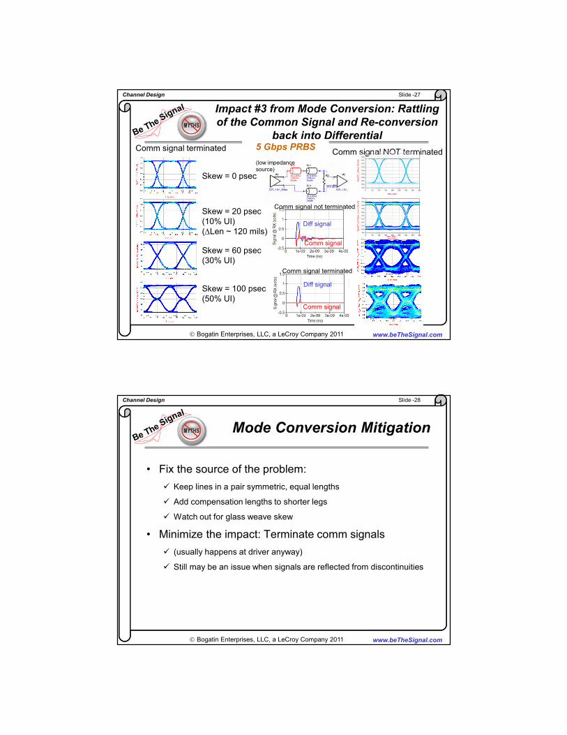
Slide -27
www.beTheSignal.com
Channel Design
Bogatin Enterprises, LLC, a LeCroy Company 2011
Impact #3 from Mode Conversion: Rattling
of the Common Signal and Re-conversion
back into Differential
Comm signal NOT terminated
Skew = 20 psec
(10% UI)
(∆Len ~ 120 mils)
Skew = 60 psec
(30% UI)
Skew = 100 psec
(50% UI)
Skew = 0 psec
Comm signal terminated 5 Gbps PRBS
(low impedance
source)
Diff signal
Comm signal
Comm signal terminated
Diff signal
Comm signal
Comm signal not terminated
Slide -28
www.beTheSignal.com
Channel Design
Bogatin Enterprises, LLC, a LeCroy Company 2011
Mode Conversion Mitigation
• Fix the source of the problem:
� Keep lines in a pair symmetric, equal lengths
� Add compensation lengths to shorter legs
� Watch out for glass weave skew
• Minimize the impact: Terminate comm signals
� (usually happens at driver anyway)
� Still may be an issue when signals are reflected from discontinuities

Slide -29
www.beTheSignal.com
Channel Design
Bogatin Enterprises, LLC, a LeCroy Company 2011
Four Chief Problems to Manage
• Losses
� Boards
� Cables
• Reflections
� Between all interfaces
� Vias
• Noise: cross talk
� Boards (return planes)
� Packages
� Connectors
• Mode conversion
� Routing
� Fiber weave
� Connectors
Mantra: LRN-M: “Losses, Reflections, Noise, Mode conversion”
At the RX
At the TX
Slide -30
www.beTheSignal.com
Channel Design
Bogatin Enterprises, LLC, a LeCroy Company 2011
For More Information
www.BeTheSignal.com
� Recent Publications
� Future class schedules
� My Blog: What I learned this month
� Recorded webinars
� www.PrintedCircuitUniversity.com for online training
Published by Prentice Hall, 2009