9400a digital oscilloscope manual - teledyne...
TRANSCRIPT
THE LeCROY MODEL 9400A
DIGITAL OSCILLOSCOPE
North American Headquarters:
LeCROY Corporation700 Chestnut Ridge RoadChestnut Ridge, NY 10977-6499U.S.A.Tel: 914-578 6097
European Headquarters:
LeCROY S.A.2, rue Pr~-de-la-FontaineCase postale 3411217 Meyrin 1 / GenevaSwitzerlandTel: 41-22-719-21-11
Serial Number
January 1990


TABLE OF CONTENTS
Section
I. GENERAL INFORMATION
Technical Data Sheet
1.11.21.31.41.51.6
WarrantyAssistance and Maintenance AgreementsDocumentation DiscrepanciesService ProcedureReturn ProcedureInitial Inspection
2. PRODUCT DESCRIPTION
2.12.22.32.42.52.62.7
Introduction9400A ArchitectureADCs and MemoriesTriggerAutomatic CalibrationDisplayManual and Programmed Control
3. INSTALLATION
3.13.23.3
Safety InformationOperating VoltageSwitching on the 9400A
4. DISPLAY LAYOUT
4.14.24.34.44.54.6
Menu FieldTime and Frequency FieldTrigger Delay FieldAbridged Front Panel Status FieldDisplayed Trace FieldMessage Field
5. MANUAL OPERATION
5.1 Front-panel Controls
5.1.1 Vertical5.1.2 Time Base5.1.3 Trigger5.1.4 Displaying Traces5.1.5 Display Control5.1.6 Screen Adjustments5.1.7 Cursors
Page Number
I-Ii-I1-21-21-21-3
2-12-12-22-32-32-32-3
3-13-13-2
4-14-24-24-24-24-3
5-1
5-15-45-65-125-125-15-15
ii

5.2 Menu Controls 5-18
5.2.15.2.25.2.35.2.45.2.55.2.5.15.2.5.2
Store MenuPanel Status MenuMemory StatusStorage and Recall of Front Panel SetupsSpecial Modes
Auto-store ModeCommon Expand Mode
5.2.6 RS-232-C Setup5.2.7 Plotter Setup
6. REAR PANEL CONTROLS AND CONNECTORS
6.16.26.36.46.5
Fuse ProtectionAccessory Power ConnectorsBattery PackGPIB and RS-232-C Port SelectionPlotter Connector
7. REMOTE OPERATIONS
7.17.27.37.4
Programmed ControlRS-232-C PortsGPIB Port (Option OP02 only)C~IB and RS-232-C Command Format
7.4.17.4.27.4.37.4.47.4.57.4.67.4.77.4.87.4.9
IntroductionCompound CommandsCommand FormatAnswers from the 9400AFlushing of 9400A Output BufferCommand Synchronization with Data AcquisitionCharacter StringsPromptErrors and Adapted Values
7.57.6
Data Block TransfersCommands
7.6.17.6.27.6.37.6.47.6.57.6.67.6.77.6.87.6.97.6.10
NotationAcquisition Parameter CommandsDisplay CommandsPlotter CommandsTransfer CommandsOther Remote CommandsCommunication Format CommandStatus Byte and Mask Register CommandsGPIB Interface Message InterpretationRS-232-C Only Commands
5-185-205-225-245-255-255-26
5-265-28
6-16-16-16-16-2
7-17-17-27-3
7-37-47-47-57-67-67-77-77-8
7-87-11
7-117-127-157-207-227-307-317-347-387-39
iii

7.77.87.97.10
Binary Format of Waveform DescriptorsFormat of Trigger Time(s)Data Addressing ConventionsInterpretation of Waveform Data Values
7-437-477-487-50
7.10.17.10.27.11
Waveform Data in 8-bit FormatWaveform Data in 16-bit Format
Use of the Service Request (SRQ) Interrupts
7-507-527-52
7.11.17.11.2
Service Request in GPIBService Request in RS-232-C
7-527-55
8. BASIC 9400A WAVEFORM MEASUREMENTS AND OPERATING PROCEDURES
8.18.28.38.4
8.58.68.78.88.98.108.118.128.138.14
8.15
Repetitive Signal AcquisitionSingle Shot AcquisitionTrace Expansion - Expand A/BSequential Recording of Single Events inSegmented MemorySlow Signal RecordingWindow TriggeringStoring and Recalling Front Panel SetupsSignal Storage in Memories C, DRedefinition Function - Expand Memories C, DAuto-Store in Memory C, DCommon Expand ModeRemote Control Via RS-232-C PortRemote Control Via GPIB (Option OP02 Only)Making a Plot when the Computer, the 9400A,and the Plotter are All Connected Togetheron a GPIB Bus (Option OP02 Only)
8-18-38-5
8-68-88-98-98-108-118-128-138-148-18
8-19Configuring the Parallel Polling (Option 0P02 0nly) 8-20
9. GETTING THE MOST OUT OF YOUR 9400A
9.19.29.39.4
Front Panel ControlsAccurate Amplitude MeasurementsAccurate Time MeasurementsAuto-calibration
9-19-19-39-4
I0. WPOI WAVEFORM PROCESSING OPTION
I0.i10.2
Processing CapabilitiesSetting up a Waveform Processing FunctionManually
I0-i10-2
10.2.110.2.210.2.310.2.410.2.510.2.6
Summed AverageContinuous AverageExtremaArithmeticFunctionsSmoothing
10-310-410-510-610-610-6
iv

11.
10.310.4
10.510.6
Remote Control of Waveform Processing FunctionsAdditional Values in the Descriptors ofProcessed WaveformsVertical Scaling UnitsIndex of Topics
Fast Fourier Waveform Processing Option(WP02, V 2.06FT)
ii.i11.211.311.4
Processing CapabilitiesModification to WP01 FunctionsFFT Processing ExamplesRemote Control of FFT Processing
11.4.111.4.2
Remote CommandsAdditional Values in the Descriptors ofFFT Processed Waveforms
11.5 FFT Application Hints
11.5.111.5.2
11.5.3
Some practical suggestionsRelationships of 9400A FFT output waveforms tothe FFT computation stepsComputation Speed of FFT
11.611.711.811.9ii. I0
FFT 9400A GlossaryErrors and WarningsTable of Nyquist FrequenciesReferencesIndex of Topics
10-8
10-1310-1510-17
II-I11-311-411-7
11-7
11-9
ii-ii
II-ii
11-1211-15
11-1611-2111-2211-2911-30
Appendix


STORE
©
0
0
0
0
0
0
0
0
0POWER
SCREENDUMP
©
11
44 43 42 ~ 40 39
100Ms/sLeCroy9400A DUAL 175MHz OSCILLOSCOPE sG,/s SELECT©
"~ I .EOEF, NE©I 45
2
3
4
5
6
7
8
9
10
46
47
48
49
INTENSITY GRID INTENSITY DUAL GRID CURSOR MEASUREMENT MODEVOLTAGE TIME MARKER
© © o o o o
12 13 14 16 17 18
REMOTE
ON
15
\0
VERT GAIN PosmoN...~+
TIME MAGNIFIER+
POSITION(
CHANNEL 1OFFSET
(p:VOLTSIDIV
CHANNEL 2OFFSET
©IVOLTSIDIV
PROBE CALIBRATOR
19 !10 21
5V 5mY 5V 5mV
I’I6ND
I
GND
OC DC
6110 HD
.,,o, ~0 ,oo,, ~0I... I,.,.
250 V pk MAX 250 Y pk MAX
@I
22
REFERENCE DIFFERENCE
TRACKING
INTERLEAVEDSAMPLING
ON
O
LEVEL / DELAY-~ -.,~+ + <..- .->-
"°
TIIIS’n ilEAnyI
COUPLING MODE
,, 1"0 ,.,-1"0LF REJ
HF RF.J loll
0’ ~0 ""’ ~0IIIOUll
SOURCE SLOPE
CIAll T 0 HIS
c.,~ .~--;-- 0UNE i~,1,0EJ[TIIO
EXTERNAL250 V pk MAX
ON
23 24 25 26
38
37
36
35
34333231
3029
2827
9400A FRONT PANELFigure 1.1

51 52 53 54 55 56 57
9400A REAR PANELFigure 1.2


For instant hard copies the 9400A’s screen dump feature sends datadirectly to the DPgO01 8-pen digital plotter.
ORDERING INFORMATIONOscilloscope and OptionsCode Description9400A/G Digital Oscilloscope9400AOP01 High-precision Option9400AOP03 Printer Option for 9400A/G9400AWP01 Waveform Processing Option9400AWP02 FFT Processing Option (requires 9400AWP01)9400AMS01 Mass Storage and Remote Control Package, in-
cluding an IBM lap-top controller, interface, cablesand software
9400AIM01 GPIB Interface for IBM-PCC computers9400CS01 Calibration Software
Oscilloscope AccessoriesOM9400A Operator’s ManualSM9400A Service Manual
US SALES OFFICES
1-800-5-LeCroyautomatically connects you to your local sales office.
WORLDWIDE
Australia: Scient. Devices Pty, Ltd, (03) 579-3622Austria: Dewetron Elektr. Messger&te GmbH, (0316) 391804Benelux: LeCroy B.V. "31~4902-89285Canada: Rayonics Sci. Inc., W. Ontario, (416) 736-1600
E. Ontario/Manitoba, (613) 521-8251Quebec, (514) 335-015W. Canada, (604) 293-1854
Denmark: Lutronic Aps, (42) 459764Finland: Labtronic OY, (90) 847144France: LeCroy Sad (1) 69073897Germany: LeCroy GmbH, (06221) 49162, (North) (0405)
A wide range of oscilloscope accessories including cameras and ascope cart (pictured) are available for the 9400A.
Oscilloscope Accessories (cont’d)CAg001CA9002CS9400DPg00194XX-FCOC9001P9010Pg010/2P9011P9100RM9400SGg001Tcg001TC9002TC9003
Camera (using Polaroid film) and HoodCamera Adapter (35mm) with HoodCertified CalibrationDigital Plotter, 8-pen A4 sizeFront CoverOscilloscope Cart10:1 Oscilloscope Probe10:1 Oscilloscope Probe with 2 m cable10:1/1:1 Oscilloscope Probe100:1 Oscilloscope ProbeAdapter Kit for Rack MountingHigh-voltage ProtectorTransit CaseProtective CoverTransit Case for 9400A and Mass Storage
Greece: Hellenic S/R Ltd., (01) 721 1140India: Electronic Ent., (02) 4137096Israel: Ammo, (03) 453157Italy: LeCroy Srl, Roma (06) 302-9646, Milano (02) 2940-5634Japan: Toyo Corp., (03) 279 0771Korea: Samduk Science & Ind., Ltd., (02) 468 04914Mexico: Nucleoelectronica SA, (905) 5693 6043New Zealand: E.C. Gough Ltd., (03) 798-740Norway: Avantec AS, (02) 630520Portugal: M.T. Brandao, Lta¯, (02) 691116Spain: Anadig Ingenieros SA, (01) 433 24 Switzerland: LeCroy SA (022) 719 21 Sweden: MSS AB, (0764) 68100Taiwan: Topward El. Inst., Ltd., (02) 601 8801United Kingdom: LeCroy Ltd., (0235) 33 114
LeCroyInnovators in Instrumentation
LeCROY CORPORATE HEADQUARTERS700 Chestnut Ridge RoadChestnut Ridge, NY 10977-6499Telephone: (914) 425-2000TWX:(710) 577-2832Fax: (914) 425-8967
LeCROY EUROPEAN HEADQUARTERS2, rue Pr~de-la-FontaineP.O. Box 3411217 Meyrin 1-Geneva, SwitzerlandTelephone: (022) 719 21 11 Telex: 41 90 Fax: (022) 782 39
Copyright @ March 1990. LeCroy is the registered trademark of LeCroy Corporation. All rights reserved. Information in this publication supersedes all earlier versions. Specifications subjectto change without notice,TDS 011/004
DIGITAL OSCILLOSCOPE175 MHz BANDWIDTH, 100 Ms/s, 5 Gs/s LeCroy
MODEL 9400A PORTABLEDUAL-CHANNEL OSCILLOSCOPE 9400A
High Bandwidth andPrecision
¯ Long Memories
¯ High-resolution Display
¯ Signal Processing and FFT
¯ Mass Storage
~(tgnal averaging improves the signal-to-noise ratio and increases sensitivity and vertical resolu-¯ Above, a function generator signal is averaged 40 times to show the details of a perturbation
p trace).
QTHE COMPLETE TEST
O AND MEASUREMENTSYSTEM
The LeCroy 9400A Digital Oscilloscope is a powerful general-purposetool for waveform recording and analysis. Combining ease of use with acomprehensive range of measurement and processing capabilities, it en-ables extremely precise measurements.
The LeCroy 9400A provides 1 75 MHz bandwidth, 100 megasamples/sec8-bit ADCs, + 2 % DC accuracy (+ 1% optional), 32K memory per chan-nel, and up to 192K of waveform storage memory¯ It is fully program mableover RS-232-C or GPIB interfaces. Plotter drivers enable color archivingvia a wide range of digital plotters.

FEATURES SPECIFICATIONSHigh bandwidth and precision - Two independentchannels, each with 175 MHz bandwidth and a high-performance 8-bit ADC, handle input signals withbetter than +2% DC accuracy (_+1% optional). The9400A features sampling rates of 100 megasamples/sec for transient events. Long memories and aversatile cursor system (including voltage, time andcross-hair cursors), give time measurements with anaccuracy of_+0.02% of the time-base setting, and reso-lution of +0.002% full scale.
High-resolution display-The 9400A’s large displayscreen produces bright, stable, razor-sharp pictures ofyour signal under any repetition rate conditions. Veryaccurate signal comparisons are possible as up to fourwaveforms (live, expanded or processed) can be dis-played simultaneously on the high-resolution screen(1024 x 1024 pixels).
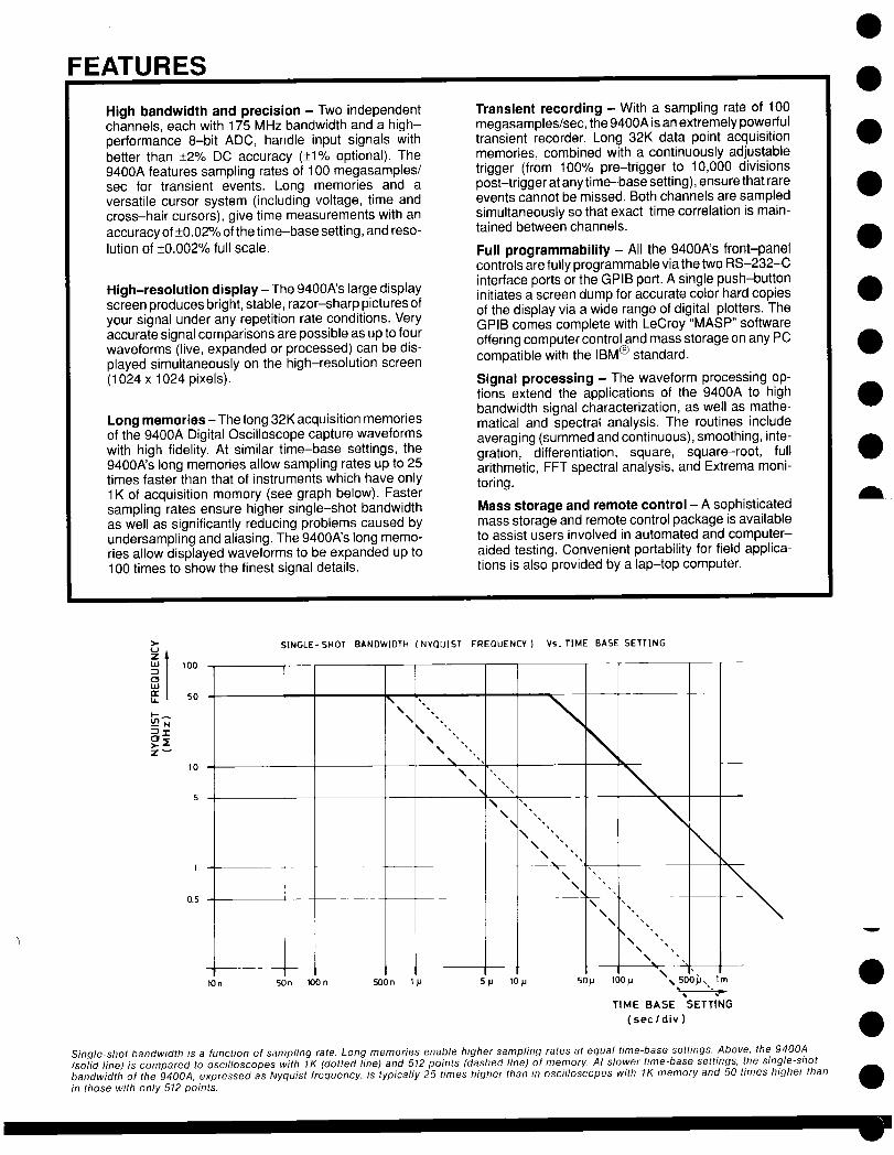
Long memories-The long 32K acquisition memoriesof the 9400A Digital Oscilloscope capture waveformswith high fidelity. At similar time-base settings, the9400A’s long memories allow sampling rates up to 25times faster than that of instruments which have only1K of acquisition memory (see graph below). Fastersampling rates ensure higher single-shot bandwidthas well as significantly reducing problems caused byundersampling and aliasing. The 9400A’s long memo-ries allow displayed waveforms to be expanded up to100 times to show the finest signal details.
Transient recording - With a sampling rate of 100megasamples/sec, the 9400A is an extremely powerfultransient recorder. Long 32K data point acquisitionmemories, combined with a continuously adjustabletrigger (from 100% pre-trigger to 10,000 divisionspost-trigger at any time-base setting), ensure that rareevents cannot be missed. Both channels are sampledsimultaneously so that exact time correlation is main-tained between channels.
Full programmability - All the 9400A’s front-panelcontrols are fully programmable via the two RS-232-Cinterface ports or the GPIB port. A single push-buttoninitiates a screen dump for accurate color hard copiesof the display via a wide range of digital plotters. TheGPIB comes complete with LeCroy "MASP" softwareoffering computer control and mass storage on any PCcompatible with the IBM® standard.
Signal processing - The waveform processing op-tions extend the applications of the 9400A to highbandwidth signal characterization, as well as mathe-matical and spectral analysis. The routines includeaveraging (summed and continuous), smoothing, inte-gration, differentiation, square, square-root, fullarithmetic, FFT spectral analysis, and Extrema moni-toring.
Mass storage and remote control - A sophisticatedmass storage and remote control package is availableto assist users involved in automated and computer-aided testing. Convenient portability for field applica-tions is also provided by a lap-top computer.
>-
~"r-
100 L
50
10
5
1
0.5
SINGLE- SHOT BANDWIDTH ( NYQUIST FREQUENCY ) Vs. TIME BASE SETT[NG
\\ "’,
I \ \\
\
\
\
\,\
\ ""i\\
\\
\
10n 5On 100 n 500n I LI .U 10 ~ 50tJ
\\
\%
\ 1-ioo~ ,,soo~,,.1~
¯ .=TIME BASE SETTING
(sec/div)
Single-shot bandwidth is a function of sampling rate. Long memories enable higher sampling rates at equal time-base settings. Above, the 9400A(solid line) is compared to oscilloscopes with 1K (dotted line) and 512 points (dashed line) of memory. At slower time-base settings, the single-shotbandwidth of the 9400A, expressed as Nyquist frequency, is typically 25 times higher than in oscilloscopes with 1K memory and 50 times higher thanin those with only 512 points.
VERTICAL ANALOG SECTIONBandwidth (- 3 dB):
@ 50 ~: DC - 175 MHz at 10 mV/div, up to 225 MHzat 1V/div;DC - 150 MHz at 5 mV/div.
@ 1 M~ AC: < 10 Hz - 100 MHz typical.@ 1 M~ DC: DC - 100 MHz typical.Single shot: DC - 50 MHz (Nyquist).
Input impedance: 1 M~//50 pF and 50 ~ +_ 1%.Channels: Two; standard BNC connector inputs.Sensitivity range: 5 mV/div to 1 V/div at 50 ~ impedanceand 5 mV/div to 5 V/div at 1 M~ impedance; detents at1-2-5, 1 : 2.5 continuously variable.
Offset: _+ 8 divisions in 0.04 division increments.
DC accuracy: Standard < + 2%, optional _< + 1%.
Noise: _< 0.45% RMS.Bandwidth limiter (- 3 dB): 30 MHz.
Max input voltage: 250 V (DC + peak AC) at 1 M~, 5 V (500 mW) or _+ 10V peak AC at 50
VERTICAL DIGITAL SECTIONADCs: One per channel, 8-bit flash.Conversion rate: Up to 100 megasamples/sec for transientsignals, up to 5 gigasamples/sec for repetitive signals, simul-taneously on both channels.
Aperture uncertainty: + 10 psec.
Overall dynamic accuracy (typical): Sine wave applied tothe BNC input for RMS curve fit at 80% full scale. The accu-racy measurement includes the front-end amplifier, sample& hold and ADC.
Input frequency Nyquist(MHz) 1.0 10.0 50.0 100.0 175.0Signal-to-noiseratio (dB)
41.9 41.9 41.9 37.1 29.9
Effective bits 7.0 7.0 7.0 6.2 5.0
Acquisition memories, Channels 1 and 2: Two, 32K 8-bitword memories (64K total) which can be segmented into 15, 31,62, 125 or 250 blocks.Reference memories, C and D: Two, 32K, 16-bit word me-mories (64K total) which can store two acquired and/orprocessed waveforms.Function memories E and F (optional): Two 32K, 16-bitword memories (64K total) for waveform processing.Glitch detection: Permanent glitch detection for eventsclown to 0.04% of the time-base setting, 10 nsec minimum.
HORIZONTAL SECTIONTime BaseRange: 2 nsec/div to 100 sec/div.Accuracy: Better than + 0.002 % of the time-base setting.Interpolator resolution: 10 psec.
Acquisition Modes
Random Interleaved Sampling (RIS) for repetitive signalsfrom 2 nsec/div to 2 ~sec/div;
Single shot for transient signals and repetitive signals from50 nsec/div to 200 msec/div;
Roll for slowly-changing signals from 500 msec/div to100 sec/div;Sequence for capturing transients in segmented memoriesof 8, 15, 31,62,125 or250 blocks.
Trigger
Sources: CHAN1, CHAN2, LINE, EXT, EXT/10.
Slope: Positive, negative, window.Coupling: AC, LF RE J, HF RE J, DC.
Modes:Sequence: stores multiple events in segmented acquisi-tion memories.Auto: automatically re-arms after each sweep. If no trig-ger occurs, one is generated at 2 Hz repetition rate.Normal: re-arms after each sweep. If no trigger occursafter 2 sec, the display is erased.Single (hold): holds display after a trigger occurs. Re-arms only when the "single" button is pressed again.
Pro-trigger: Adjustable in 0.2% increments, to 100%.
Post-trigger delay: Adjustable in 0.02 division incrementsup to 10,000 divisions.
External trigger input: 1M~, < 30pE 250V max., + 2V inEXT, + 20V in EXT/10.Rate: > 200 MHz.
SELF TESTSAuto-calibration: Performed every 20 minutes or whenevethe gain or time-base parameters are changed; providesaccuracies of:
DC gain: + 2% (+ 1% optional) of full scale;Offset: + 0.5% of full scale (50~ only);Time: 20 psec RMS.
During the warming-up period, auto-calibration is carried OLat 1 minute intervals unless the oscilloscope is in single orsequence trigger mode.
DISPLAYCRT: 12.5 ×17.5 cm (5 x 7 inches); magnetic deflection; vector graphics system.Resolution: 1024 x 1024 addressable points.
Grid: Internally generated; separate intensity control for gricand waveforms. Single and dual grid mode.Expansion: Dual zoom horizontal expansion operates simutaneously on live, stored and processed waveforms,expanding up to 100 times. Vertical expansion from 0.4 up tc2 times for non-processed waveforms, up to 10 times forprocessed waveforms.
Screen dump: Single or multi-pen digital plotters are menuselected. The 9400A supports the HP 7400 series, as well a,the Tektronix 4662, Philips PM 8151, Graphtek WX 4638/6.and compatible models. Screen dumps are activated by afront-panel push-button.
Cursors: Two time cursors give time resolution of _+ 0.2% cfull scale for unexpanded traces; up to +_ 0.002% for expan-ded traces. The corresponding frequency information is alscprovided. Two voltage cursors measure voltage differencesto 0.2% of full scale for each trace.A cross-hair marker measures absolute voltage versussignal ground as well as the time relative to the trigger.

DIGITAL OSCILLOSCOPE175 MHz BANDWIDTH, 100 Ms/s, 5 Gs/s LeCroy
MODEL 9400A PORTABLEDUAL-CHANNEL OSCILLOSCOPE 9400A
¯ High Bandwidth andPrecision
¯ Long Memories
¯ High-resolution Display
¯ Signal Processing and FFT
¯ Mass Storage
"ignal averaging improves the signal-to-noise ratio and increases sensitivity and vertical resolu-in. Above, a function generator signal is averaged 40 times to show the details of a perturbation
(top trace).
THE COMPLETE TESTAND MEASUREMENT
SYSTEM
The LeCroy 9400A Digital Oscilloscope is a powerful general-purposetool for waveform recording and analysis. Combining ease of use with acomprehensive range of measurement and processing capabilities, it en-ables extremely precise measurements.
The LeCroy 9400A provides 175 MHz bandwidth, 100 megasamples/Sec8-bit ADCs, + 2 % DC accuracy (+ 1% optional), 32K memory per chan-nel, and up to 192K of waveform storage memory. It is fully programmableover RS-232-C or GPIB interfaces. Plotter drivers enable color archivingvia a wide range of digital plotters.
FEATURES
High bandwidth and precision - Two independentchannels, each with 175 MHz bandwidth and a high-performance 8-bit ADC, handle input signals withbetter than +_2% DC accuracy (.-_1% optional). The9400A features sampling rates of 100 megasamples/sec for transient events. Long memories and aversatile cursor system (including voltage, time andcross-hair cursors), give time measurements with anaccuracy of__0.02% of the time-base setting, and reso-lution of _+0.002% full scale.
High-resolution display- The 9400A’s large displayscreen produces bright, stable, razor-sharp pictures ofyour signal under any repetition rate conditions. Veryaccurate signal comparisons are possible as up to fourwaveforms (live, expanded or processed) can be dis-played simultaneously on the high-resolution screen(1024 x 1024 pixels).
Long memories- The long 32K acquisition memoriesof the 9400A Digital Oscilloscope capture waveformswith high fidelity. At similar time-base settings, the9400A’s long memories allow sampling rates up to 25times faster than that of instruments which have only1K of acquisition memory (see graph below). Fastersampling rates ensure higher single-shot bandwidthas well as significantly reducing problems caused byundersampling and aliasing. The 9400A’s long memo-ries allow displayed waveforms to be expanded up to100 times to show the finest signal details.
Transient recording - With a sampling rate of 100megasamples/sec, the 9400A is an extremely powerfultransient recorder. Long 32K data point acquisitionmemories, combined with a continuously adjustabletrigger (from 100% pre-trigger to 10,000 divisionspost-trigger at any time-base setting), ensure that rareevents cannot be missed. Both channels are sampledsimultaneously so that exact time correlation is main-tained between channels.
Full programmability - All the 9400A’s front-panelcontrols are fully programmable via the two RS-232-Cinterface ports or the GPIB port. A single push-buttoninitiates a screen dump for accurate color hard copiesof the display via a wide range of digital plotters. TheGPIB comes complete with LeCroy "MASP" softwareoffering computer control and mass storage on any PCcompatible with the IBM® standard.
Signal processing - The waveform processing op-tions extend the applications of the 9400A to highbandwidth signal characterization, as well as mathe-matical and spectral analysis. The routines includeaveraging (summed and continuous), smoothing, inte-gration, differentiation, square, square-root, fullarithmetic, FFT spectral analysis, and Extrema moni-toring.
Mass storage and remote control - A sophisticatedmass storage and remote control package is availableto assist users involved in automated and computer-aided testing. Convenient portability for field applica-tions is also provided by a lap-top computer.
100
50
l0 -
5 -
0.5 --
SINGLE-SHOT BANDWIDTH (NYQUIST FREQUENCY)
\
\\
\\
\\
\
Vs. TIME BASE SETTING
\
\\
1On 50n lO0n SOOn Ip 5p 10FI 50H
\
\\
\
\\
\%. "¯
\
TIME BASE SETTING
(sec/div )
Single-shot bandwidth is a function of sampling rate. Long memories enable higher sampling rates at equal time-base settings. Above, the 9400A(solid line) is compared to oscilloscopes with 1K (dotted line) and 512 points (dashed line) of memory. At slower time-base settings, the single-shotbandwidth of the 9400A, expressed as Nyquist frequency, is typically 25 times higher than in oscilloscopes with 1K memory and 50 times higher than
in those with only 512 points.

SPECIFICATIONS
VERTICAL ANALOG SECTION
Bandwidth (- 3 dB):@ 50 ~2: DC - 175 MHz at 10 mV/div, up to 225 MHz
at 1V/div;DC - 150 MHz at 5 mV/div.
@ 1 M(2 AC: < 10 Hz- 100 MHz typical.@ 1 M(~ DC: DC - 100 MHz typical.Single shot: DC - 50 MHz (Nyquist).
Input impedance: 1 M~2//50 pF and 50 ~-2 + 1%.Channels: Two; standard BNC connector inputs.Sensitivity range: 5 mV/div to 1 V/div at 50 (2 impedanceand 5 mV/div to 5 V/div at 1 M~) impedance; detents at1-2-5, 1 : 2.5 continuously variable.
Offset: + 8 divisions in 0.04 division increments.
DC accuracy: Standard _< + 2%, optional _< _+ 1%.
Noise: < 0.45% RMS.Bandwidth limiter (- 3 dB): 30 MHz.
Max input voltage: 250 V (DC + peak AC) at 1 M~2, 5 V (500 mW) or _+ 10V peak AC at 50 (~.
VERTICAL DIGITAL SECTIONADCs: One per channel, 8-bit flash.Conversion rate: Up to 100 megasamples/sec for transientsignals, up to 5 gigasamples/sec for repetitive signals, simul-taneously on both channels.
Aperture uncertainty: _+ 10 psec.Overall dynamic accuracy (typical): Sine wave applied tothe BNC input for RMS curve fit at 80% full scale. The accu-racy measurement includes the front-end amplifier, sample& hold and ADC.
Input frequency Nyquist(MHz) 1.0 10.0 50.0 100.0 175.0
Signal-to-noise 41.9 37.1 29.9ratio (dB)
41.9 41.9
Effective bits 7.0 7.0 7.0 6.2 5.0
Acquisition memories, Channels 1 and 2: Two, 32K 8-bitword memories (64K total) which can be segmented into 15, 31,62, 125 or 250 blocks.Reference memories, C and D: Two, 32K, 16-bit word me-mories (64K total) which can store two acquired and/orprocessed waveforms.Function memories E and F (optional): Two 32K, 16-bitword memories (64K total) for waveform processing.Glitch detection: Permanent glitch detection for eventsdown to 0.04% of the time-base setting, 10 nsec minimum.
HORIZONTAL SECTIONTime BaseRange: 2 nsec/div to 100 sec/div.Accuracy: Better than + 0.002 % of the time-base setting.Interpolator resolution: 10 psec.
Acquisition Modes
Random Interleaved Sampling (RIS) for repetitive signalsfrom 2 nsec/div to 2 #sec/div;
Single shot for transient signals and repetitive signals from50 nsec/div to 200 msec/div;
Roll for slowly-changing signals from 500 msec/div to100 sec/div;
Sequence for capturing transients in segmented memoriesof 8, 15, 31,62, 125 or 250 blocks.
Trigger
Sources: CHAN1, CHAN2, LINE, EXT, EXT/10.Slope: Positive, negative, window.
Coupling: AC, LF RE J, HF REJ, DC.
Modes:Sequence: stores multiple events in segmented acquisi-tion memories.Auto: automatically re-arms after each sweep. If no trig-ger occurs, one is generated at 2 Hz repetition rate.Normal: re-arms after each sweep. If no trigger occursafter 2 sec, the display is erased.Single (hold): holds display after a trigger occurs. Re-arms only when the "single" button is pressed again.
Pre-trigger: Adjustable in 0.2% increments, to 100%.
Post-trigger delay: Adjustable in 0.02 division incrementsup to 10,000 divisions.
External trigger input: 1M,(2, < 30pF, 250V max., _+ 2V inEXT, 4- 20V in EXT/10.Rate: > 200 MHz.
SELF TESTSAuto-calibration: Performed every 20 minutes or wheneverthe gain or time-base parameters are changed; providesaccuracies of:
DC gain: + 2% (+ 1% optional) of full scale;Offset: + 0.5% of full scale (50~ only);Time: 20 psec RMS.
During the warming-up period, auto-calibration is carried outat 1 minute intervals unless the oscilloscope is in single orsequence trigger mode.
DISPLAYCRT: 12.5 x17.5 cm (5 x 7 inches); magnetic deflection; vec-tor graphics system.
Resolution: 1024 x 1024 addressable points.
Grid: Internally generated; separate intensity control for gridand waveforms. Single and dual grid mode.
Expansion: Dual zoom horizontal expansion operates simul-taneously on live, stored and processed waveforms,expanding up to 100 times. Vertical expansion from 0.4 up to2 times for non-processed waveforms, up to 10 times forprocessed waveforms.
Screen dump: Single or multi-pen digital plotters are menuselected. The 9400A supports the HP 7400 series, as well asthe Tektronix 4662, Philips PM 8151, Graphtek WX 4638/6,and compatible models. Screen dumps are activated by afront-panel push-button.
Cursors: Two time cursors give time resolution of + 0.2% offull scale for unexpanded traces; up to + 0.002% for expan-ded traces. The corresponding frequency information is alsoprovided. Two voltage cursors measure voltage differencesto 0.2% of full scale for each trace.A cross-hair marker measures absolute voltage versussignal ground as well as the time relative to the trigger.

For instant hard copies the 9400A’s screen dump feature sends datadirectly to the DP9001 8-pen digital plotter.
ORDERING INFORMATIONOscilloscope and OptionsCode Description9400A/G Digital Oscilloscope9400AOP01 High-precision Option9400AOP03 Printer Option for 9400A/G9400AWP01 Waveform Processing Option9400AWP02 FFT Processing Option (requires 9400AWP01)9400AMS01 Mass Storage and Remote Control Package, in-
cluding an IBM lap-top controller, interface, cablesand software
9400AIM01 GPIB Interface for IBM-PCC computers9400CS01 Calibration Software
Oscilloscope AccessoriesOM9400A Operator’s ManualSM9400A Service Manual
US SALES OFFICES
1-800-5-LeCroyautomatically connects you to your local sales office.
WORLDWIDEAustralia: Scient. Devices Pty, Ltd, (03) 579-3622Austria: Dewetron Elektr. Messger~te GmbH, (0316) 391804Benelux: LeCroy B.V. "31-4902-89285Canada: Rayonics Sci. Inc., W. Ontario, (416) 736-1600
E. Ontario/Manitoba, (613) 521-8251Quebec, (514) 335-015W. Canada, (604) 293-1854
Denmark: Lutronic Aps, (42) 459764Finland: Labtronic OY, (90) 847144France: LeCroy Sad (1) 69073897Germany: LeCroy GmbH, (06221)49162, (North) (0405)42713
A wide range of oscilloscope accessories including cameras and ascope cart (pictured) are available for the 9400A.
Oscilloscope Accessories (cont’d)CA9001CA9002CS9400DP900194XX-FCOC9001P9010P9010/2P9011P9100RM9400SG9001TC9001TC9002TC9003
Camera (using Polaroid film) and HoodCamera Adapter (35mm) with HoodCertified CalibrationDigital Plotter, 8-pen A4 sizeFront CoverOscilloscope Cart10:1 Oscilloscope Probe10:1 Oscilloscope Probe with 2 m cable10:1/1:1 Oscilloscope Probe100:1 Oscilloscope ProbeAdapter Kit for Rack MountingHigh-voltage ProtectorTransit CaseProtective CoverTransit Case for 9400A and Mass Storage
Greece: Hellenic S/R Ltd., (01) 721 1140India: Electronic Ent., (02) 4137096Israel: Ammo, (03) 453157Italy: LeCroy Srl, Roma (06) 302-9646, Milano (02) 2940-5634Japan: Toyo Corp., (03) 279 0771Korea: Samduk Science & Ind., Ltd., (02) 468 04914Mexico: Nucleoelectronica SA, (905) 5693 6043New Zealand: E.C. Gough Ltd., (03) 798-740Norway: Avantec AS, (02) 630520Portugal: M.T. Brandao, Lta., (02) 691116Spain: Anadig Ingenieros SA, (01) 433 24 Switzerland: LeCroy SA (022) 719 21 Sweden: MSS AB, (0764) 68100Taiwan: Topward El. Inst., Ltd., (02) 601 8801United Kingdom: LeCroy Ltd., (0235) 33 114
LeCroyInnovators in Instrumentation
LeCROY CORPORATE HEADQUARTERS700 Chestnut Ridge RoadChestnut Ridge, NY 10977-6499Telephone: (914) 425-2000TWX:(710) 577-2832Fax: (914) 425-8967
LeCROY EUROPEAN HEADQUARTERS2, rue Pre-de-la-FontaineP.O. Box 3411217 Meyrin 1-Geneva, SwitzerlandTelephone: (022) 719 21 11 Telex: 41 90 Fax: (022) 782 39
Copyright (~ March 1990. LeCroy is the registered trademark of LeCroy Corporation. All rights reserved. Information in this publication supersedes all earlier versions. Specifications subjectto change without notice.TDS 011/004
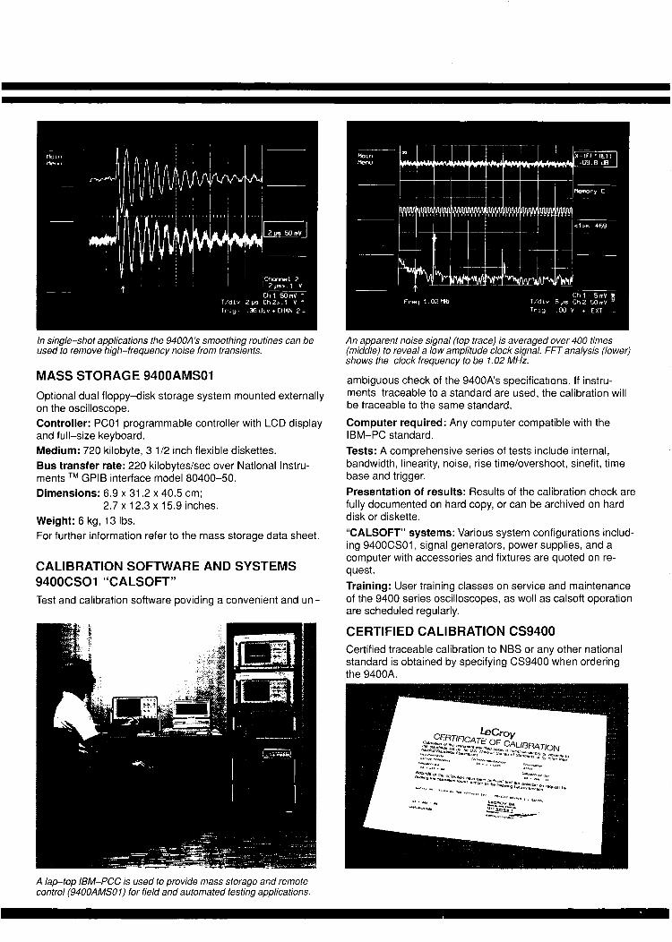
In single-shot applications the 9400A’s smoothing routines can beused to remove high-frequency noise from transients.
MASS STORAGE 9400AMS01Optional dual floppy-disk storage system mounted externallyon the oscilloscope.Controller: PC01 programmable controller with LCD displayand full-size keyboard.Medium: 720 kilobyte, 3 1/2 inch flexible diskettes.Bus transfer rate: 220 kilobytes/sec over National Instru-ments TM GPIB interface model 80400-50.Dimensions: 6.9 x 31.2 x 40.5 cm;
2.7 x 12.3 x 15.9 inches.Weight: 6 kg, 13 Ibs.For further information refer to the mass storage data sheet.
CALIBRATION SOFTWARE AND SYSTEMS9400CSO1 "CALSOFT"Test and calibration software poviding a convenient and un-
An apparent noise signal (top trace) is averaged over 400 times(middle) to reveal a low amplitude clock signal. FFT analysis (lower)shows the clock frequency to be 1.02 MHz.
ambiguous check of the 9400A’s specifications. If instru-ments traceable to a standard are used, the calibration willbe traceable to the same standard.
Computer required: Any computer compatible with theIBM-PC standard.Tests: A comprehensive series of tests include internal,bandwidth, linearity, noise, rise time/overshoot, sinefit, timebase and trigger.Presentation of results: Results of the calibration check arefully documented on hard copy, or can be archived on harddisk or diskette."CALSOFT" systems: Various system configurations includ-ing 9400CS01, signal generators, power supplies, and acomputer with accessories and fixtures are quoted on re-quest.Training: User training classes on service and maintenanceof the 9400 series oscilloscopes, as well as calsoft operationare scheduled regularly.
CERTIFIED CALIBRATION CS9400Certified traceable calibration to NBS or any other nationalstandard is obtained by specifying CS9400 when orderingthe 9400A.
A lap-top IBM-PCC is used to provide mass storage and remotecontrol (9400AMSO 1) for field and automated testing applications.

Time and cross-hair cursors indicate Hz and dB or volt val-ues when an FFT spectrum analysis is made.Menus:
Standard: Waveform storage; acquisition parameters;memory status; store/recall front-panel configurations,RS-232-C configuration; plotter setup.Optional: (WP01/WP02) averaging, arithmetic, functions,extrema, smoothing, FFT and frequency domain averag-ing.
REMOTE CONTROLAll the front-panel controls, including variable gain, offsetand position controls (not cursor positioning), and all the in-ternal functions are programmable.RS-232-C ports: Two: for computer/terminal control andplotter connection. Asynchronous up to 19200 baud.GPIB port: (IEEE-488). Configured as talker/listener forcomputer control and fast data transfer; 400 kilobytes/secmaximum. ASCII or binary. The address switches are on therear panel.It includes LeCroy MS02 (MASP) IBM-PC-based softwarefor mass storage and remote control applications. For furtherdetails on MASP software, please refer to the MS01/02 datasheet.
PROBESProbe calibration: 976 Hz square wave, 1 V p-p +_ 1%.Standard probes: Two model P9010, xl0 attenuating pas-sive probes with 10 M~ input impedance in parallel with a5.5 pF capacitance.Probe power: Two power outlets on the rear panel provide_+ 15 V and + 5 V DC for active probes.
GENERALTemperature: 5 to 40°C rated; to 50°C operating.Humidity: 80%EMI Immunity: The 9400A complies with the following stan-dards: IEC 801, VDE 0871, FCC PART 15 and SEV.Safety standards: The 9400A complies with the following:IEC-348, ASE 3453 and VDE 0411.Power required: 110 or 220 V AC, 48 to 65 Hz, 200 W.Battery backup: NiCd batteries maintain front-panel set-tings for 6 months minimum.
Dimensions: (HWD) 19.2 x 36.5 × 46.5 cm,(7 1/2 x 14 3/8 x 18 3/8 inches).
Weight: 14 kg (30 Ibs) net, 20 kg (44 Ibs) shipping.Warranty: 2 years.
OPTIONS FOR THE 9400A9400AOP01 : _+ 1% DC high-precision option. A certificate oftraceability is provided with this option.9400AOP03: Printer drive for HP 2225 Think Jet.
WAVEFORMPROCESSING 9400AWP01, AND9400AWP02Routines are called and set up via menus. Extensive signalprocessing in both time and frequency domains is provided
by optional firmware packages. These include FFT spectrumanalysis, arithmetic functions, integration, differentiation,square root, square, averaging (continuous and summation)and smoothing, as well as Extrema monitoring.For additional information refer to data sheets WP01 andWP02.
120
110
100
90
80o
70=
60=
50-
,t, 0~
30=
20=
10=
0h10
\\\
50 t00 500 1000
\\
5000 10000 50000
RECORD LENGTH (no. of points)
With option WPO 1 installed, the 9400A becomes a fast signal a verager(both summation and continuous). A s many as 100, 000 points/sec areaveraged with record lengths chosen by the user up to a maximum of32,000. The graph above displays the relationship between recordlength and the number of signals/sec averaged.
5o
20
u® 10u3
uJ
F- 5-
//
//
JJ
J
u
i 2 ____
t
,5~
.2
50 125 250 625 1250 2500 6250 12500 25000
RECORD LENGTH (Points)
FFT execution time as a function of record length, including window cal-culations and display generation, is expressed in the graph above.

WAVEFORM PROCESSING PACKAGEINCLUDING AVERAGING, INTEGRATION, DIFFERENTIATION LeCroL
WP01 WAVEFORM PROCESSING FIRMWAREFOR MODEL 9400A DIGITAL OSCILLOSCOPE 9400AWP01
¯ Averaging - Summationand Continuous
¯ Arithmetic - including Addition,Subtraction, and Multiplication
Functions -includingIntegration, Differentiation,and Square Root
Extrema Mode - Storage ofExtreme Positive and NegativeValues
¯ Smoothing - Reduction ofNoise on Single Events
s~raining different mathematical functions together, the WP01 waveform processing packageerform complex measurement sequences with ease. Above, a damped sine wave (top) ed (middle) and then integrated (bottom) allowing RMS mesurements to be calculated.
FOR SIGNAL¯ CHARACTERIZATION
AND ANALYSIS
The LeCroy WP01 Waveform Processing Firmware Package offers powerfulroutines that extend the use of the 9400A to signal characterization, mathe-matical analysis, and post-processing of single events. Ordered as anoption, or retrofitted, WP01 allows for further extensions of the 9400A’s pro-cessing capabilities with other firmware packages.
The LeCroy 9400A provides 175 MHz bandwidth, 100 megasamples/sec8-bit ADCs, +2% DC accuracy (+1% optional), 32K memory per channel,and up to !92K of waveform storage memory. It is fully programmable overRS-232-C ’or opti0rlal GPIB interfaces. Plotter drivers enable color archivingvia a wide range of digital plotters.
FEATURES
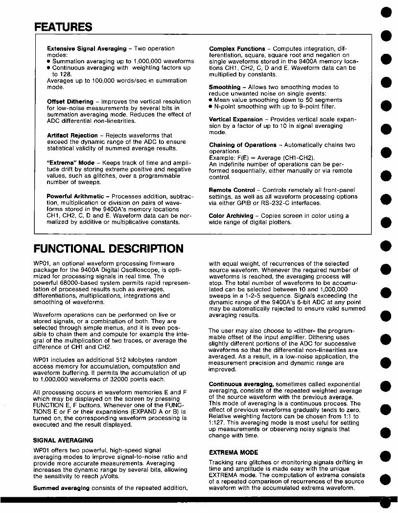
Extensive Signal Averaging - Two operationmodes:¯ Summation averaging up to 1,000,000 waveforms¯ Continuous averaging with weighting factors up
to 128.Averages up to 100,000 words/see in summationmode.
Offset Dithering - Improves the vertical resolutionfor low-noise measurements by several bits insummation averaging mode. Reduces the effect ofADC differential non-linearities.
Artifact Rejection - Rejects waveforms thatexceed the dynamic range of the ADC to ensurestatistical validity of summed average results.
"Extrema" Mode - Keeps track of time and ampli-tude drift by storing extreme positive and negativevalues, such as glitches, over a programmablenumber of sweeps.
Powerful Arithmetic - Processes addition, subtrac-tion, multiplication or division on pairs of wave-forms stored in the 9400A’s memory locationsCH1, CH2, C, D and E. Waveform data can be nor-malized by additive or multiplicative constants.
Complex Functions - Computes integration, dif-ferentiation, square, square root and negation onsingle waveforms stored in the 9400A memory loca-tions CH1, CH2, C, D and E. Waveform data can bemultiplied by constants.
Smoothing - Allows two smoothing modes toreduce unwanted noise on single events:¯ Mean value smoothing down to 50 segments¯ N-point smoothing with up to 9-point filter.
Vertical Expansion - Provides vertical scale expan-sion by a factor of up to 10 in signal averagingmode.
Chaining of Operations - Automatically chains twooperations.Example: F(E) = Average (CH1-CH2).An indefinite number of operations can be per-formed sequentially, either manually or via remotecontrol.
Remote Control - Controls remotely all front-panelsettings, as well as all waveform processing optionsvia either GPIB or RS-232-C interfaces.
Color Archiving - Copies screen in color using awide range of digital plotters.
FUNCTIONAL DESCRIPTIONWP01, an optional waveform processing firmwarepackage for the 9400A Digital Oscilloscope, is opti-mized for processing signals in real time. Thepowerful 68000-based system permits rapid represen-tation of processed results such as averages,differentiations, multiplications, integrations andsmoothing of waveforms.
Waveform operations can be performed on live orstored signals, or a combination of both. They areselected through simple menus, and it is even pos-sible to chain them and compute for example the inte-gral of the multiplication of two traces, or average thedifference of CH1 and CH2.
WP01 includes an additional 512 kilobytes randomaccess memory for accumulation, computation andwaveform buffering. It permits the accumulation of upto 1,000,000 waveforms of 32000 points each.
All processing occurs in waveform memories E and Fwhich may be displayed on the screen by pressingFUNCTION E, F buttons. Whenever one of the FUNC-TIONS E or F or their expansions (EXPAND A or B) turned on, the corresponding waveform processing isexecuted and the result displayed.
SIGNAL AVERAGING
WP01 offers two powerful, high-speed signalaveraging modes to improve signal-to-noise ratio andprovide more accurate measurements. Averagingincreases the dynamic range by several bits, allowingthe sensitivity to reach #Volts.
Summed averaging consists of the repeated addition,
with equal weight, of recurrences of the selectedsource waveform. Whenever the required number ofwaveforms is reached, the averaging process willstop. The total number of waveforms to be accumu-lated can be selected between 10 and 1,000,000sweeps in a 1-2-5 sequence. Signals exceeding thedynamic range of the 9400A’s 8-bit ADC at any pointmay be automatically rejected to ensure valid summedaveraging results.
The user may also choose to ,,dither,, the program-mable offset of the input amplifier. Dithering usesslightly different portions of the ADC for successivewaveforms so that the differential non-linearities areaveraged. As a result, in a low-noise application, themeasurement precision and dynamic range areimproved.
Continuous averaging, sometimes called exponentialaveraging, consists of the repeated weighted averageof the source waveform with the previous average.This mode of averaging is a continuous process. Theeffect of previous waveforms gradually tends to zero.Relative weighting factors can be chosen from 1:1 to1:127. This averaging mode is most useful for settingup measurements or observing noisy signals thatchange with time.
EXTREMA MODETracking rare glitches or monitoring signals drifting intime and amplitude is made easy with the uniqueEXTREMA mode. The computation of extrema consistsof a repeated comparison of recurrences of the sourcewaveform with the accumulated extrema waveform.
Whenever a given data point of the new waveformexceeds the existing data point of the accumulatedextrema waveform it replaces it. In this way the maxi-mum and/or minimum envelope of all waveforms isaccumulated up to a maximum of 1,000,000 sweeps.
ARITHMETIC
WP01 also offers basic arithmetic operations such asaddition, subtraction, division, and multiplication.These arithmetic functions can be performed on twosource waveforms on a point by point basis. Differentvertical gains and offsets of the two sources are auto-matically taken into account. However, both sourcewaveforms must have the same time-base setting. Thefirst waveform may be multiplied by a constant factorand offset by a constant.
MATHEMATICAL FUNCTIONSMathematical functions such as negation, square,square root, integral and differentiation are performedon a single source waveform. The waveform may bemultiplied by a constant factor and may be offset by aconstant. Arithmetical and mathematical functions maybe chained by using memory C and D.
SMOOTHINGWP01 provides two types of smoothing to decreasesignal noise of single transient acquisitions.
Mean value smoothing divides the acquired signalinto a chosen number of segments and then gener-ates the smoothed waveform in which each displayedpoint corresponds to the mean value of "n" pointscontained in the corresponding segment. The numberof segments can be between 50 and 32000. Meanvalue smoothing takes all digitized points on thescreen into account.
N-point smoothing applies a moving average of Npoints symmetrically placed around each of the 50 to32000 selected points for display.
Each selected point Yk is replaced in the smoothedwaveform by a processed point Y’k corresponding to:
(N-1)/2
Y’ (k) = C(n) Y(k+n)
n= -(N-1)/2
where, in case of a 3-point filter,N -- 3; C1 --- 1/4; Co -- 1/2; C1 = 1/4
SPECIFICATIONS
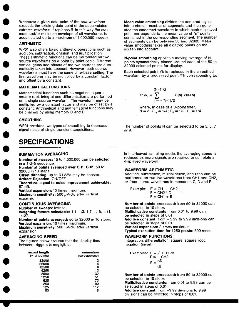
SUMMATION AVERAGINGNumber of sweeps: 10 to 1,000,000 can be selectedin a 1-2-5 sequence.Number of points averaged over CH1, CH2:50 to32000 in 10 steps.Offset dithering: up to 6 LSBs may be chosen.Artifact Rejection: ON/OFFTheoretical signal-to-noise improvement achievable:
The number of points N can be selected to be 3, 5, 7or 9.
In interleaved sampling mode, the averaging speed isreduced as more signals are required to complete adisplayed waveform.
57 dB.Vertical expansion: 10 times maximum.Maximum sensitivity: 500/~V/div after verticalexpansion.
CONTINUOUS AVERAGINGNumber of sweeps: infinite.
WAVEFORM ARITHMETICAddition, subtraction, multiplication, and ratio can beperformed on two live waveforms from CH1 and CH2,or from stored waveforms in memories C, D and E.
E = CH1 - CH2F = CH2 * DF=CH1 +E
Example:
Weighting factors selectable: 1:1, 1:3, 1:7, 1:15, 1:31,1:127.Number of points averaged: 50 to 32000 in 10 steps.Vertical expansion: 10 times maximum.Maximum sensitivity: 500/JV/div after verticalexpansion.
AVERAGING SPEEDThe figures below assume that the display time
Number of points processed: from 50 to 32000 canbe selected in 10 steps.Multiplicative constants: from 0.01 to 9.99 canbe selected in steps of 0.01.Additive constant: from - 9.99 to 9.99 divisions canbe selected in steps of 0.01.Vertical expansion: 2 times maximum.Typical execution time for 1250 points: 600 msec.
WAVEFORM FUNCTIONSIntegration, differentiation, square, square root,
between triggers is negligible:
record length summation(= of points) (sweeps/sec)
32000 325000 412500 66250 132500 321250 51625 73250 100125 11250 118
negation (invert).
Examples: E=./’ CH1 dtF = - CH2
dDE=dt
Number of points processed: from 50 to 32000 canbe selected in 10 steps.Multiplicative constants: from 0.01 to 9.99 can beselected in steps of 0.01.Additive constant: from -9.99 divisions to 9.99divisions can be selected in steps of 0.01.

Vertical expansion: 2 times maximum.Typical execution time for 1250 points:400-1000 msec.
MEAN VALUE SMOOTHINGNumber of adjacent blocks processed: 50 to 32000 in10 steps,Number of points per block: varies with the time baseand the number of blocks selected,Typical execution time for 1250 points: 700 msec.
N-POINT SMOOTHINGFilter coefficients with weighting factors for successivedata points:3 point - (1:2:1) 1/45 point - (1:4:6:4:1) 1/167 point - (1:6:15:20:15:6:1) 1/649 point- (1:8:28:56:70:56:28:8:1) 1/256.
Number of points processed: 50 to 32000 in 10 steps.Vertical expansion: 2 times maximum.Typical execution time of 1250 points: 500 msec.
EXTREMA MODELogs all extreme values of a waveform over a pro-grammable number of sweeps. Maxima and minimaare displayed separately by ROOF and FLOOR traces.
Number of sweeps: selected in a 1-2-5 sequencefrom 1 up to 1,000,000.Number of points processed: 50 to 32000 in 10 steps.Glitches as short as 10 nsec or 0.04% of the time-base setting are displayed.Vertical expansion: 2 times maximum.Typical execution time for 1250 points: 300 msec.
CHAINING OF OPERATIONSTwo functions can be automatically chained usingfunctions E and F.
Example: E = CH1 - CH2F = summed average of E
Manual chaining using memory C and D forintermediate results may continue indefinitely.
REMOTE CONTROLAll front-panel controls and Waveform Processingfunctions are fully programmable via either the9400A’s GPIB or RS-232-C interfaces. Simple English-like mnemonics are used.
STORED FRONT PANELSUp to 7 front-panel setups, including WP01 menus,can be stored and recalled by the menu buttons atthe left side of the 9400A screen.
The +_ 1 V amplitude sine wave in channel 1 (upper trace) is squared(function E: 1 * 1, lower trace) and then integrated (functions F:IE).The value of the integral between the two cursors is 4.00 pV2s. theRMS value can be calculated with the formula RMS =( 1_. ,/" V2dt)I/2 In this case: RMS = (1. 414V2s)1/2 = 0.707 V.At 8ps
A fast negative going signal at 5 nsec/div (upper trace) recorded Random Interleaved Sampling mode is inverted and stored inmemory C (lower trace). Integral and differential are shown function E and function F. The area under the inverted curve ismeasured by first defining the area with the time cursors and thenreading the value of C, In this case: 11.44 nVs.
LeCroyInnovators in Instrumentation
LeCROY CORPORATE HEADQUARTERS700 Chestnut Ridge RoadChestnut Ridge, NY 10977-6499Telephone:(914) 578-6097
800-5-LeCroy (532 769)TWX: (710) 577-2832Fax: (914) 425-8967
LeCROY EUROPEAN HEADQUARTERSRoute du Nant-d’Avri1101P.O. Box 3411217 Meyrin 1-Geneva, SwitzerlandTelephone:(022) 823355 Telex: 419058Fax: (022) 823915
Other sales and service representatives throughout the world.
Copyright © January 1989 LeCroy is the registered trademark of LeCroy Corporation All rights reserved¯ Information in this publication supersedes all earlier versions. Specifications subject to changewithout noticeTDS 013/QO2

FAST FOURIER PROCESSING PACKAGE25,000 POINT TRANSFORMS, SPECTRAL AVERAGING LeCroy
WP02 SPECTRUM ANALYSIS FIRMWAREFOR MODEL 9400A DIGITAL OSCILLOSCOPE 9400AWP02
¯ 50 to 25,000 point FFTs overTwo Channels Simultaneously
¯ Frequency Resolution from1 Milli-Hz to 50 MHz
¯ Up to 5 GS/sec Sampling Rate
¯ Time and Frequency DomainAveraging
Wide selection of FFT DisplayFormats and WindowFunctions
~nodulated signal (top trace) is analyzed in the frequency domain using the 9400A’s FFT~cessing capability which provides power (middle) and magnitude (lower) information.
5ide lobes 6 kHz from the fundamental frequency are clearly visible.
FREQUENCY DOMAINMEASUREMENTS
AND ANALYSIS
The WP02 Spectrum Analysis Firmware Package brings powerful FFTroutines to extend the capabilities of the 9400A Digital Oscilloscope intofrequency domain measurement and analysis. It is available as an option,or may be retrofitted.
The LeCroy 9400A provides 175 MHz bandwidth, 100 megasamples/sec8-bit ADCs, +2% DC accuracy (+__1% optional), 32K memory per channel,and up to 192K of waveform storage memory. It is fully programmable overRS-232-C or optional GPIB interfaces. Plotter drivers enable color archivingvia a wide range of digital plotters.

FEATURES
Long Record Transforms - Extremely long recordFFTs (up to 25,000 points) provide significantsignal-to-noise ratio improvement on singlephenomena.
Wide Band Frequency Domain Analysis - Coverswide DC to 175 MHz bandwidth with highresolution in the frequency domain.
High Sampling Rates - Up to 5 gigasamples/seceffectively eliminates atiasing errors.
Broad Spectrum Coverage - Executes FFTs overrecord lengths as long as 25,000 data pointsgiving up to 12,500 spectral components at almostany sampling rate.
Dual Input Channels - Both input channels can beanalyzed simultaneously to allow comparison ofindependent signals for common frequency-domain characteristics.
Fast Processing - FFTs are processed anddisplayed rapidly, e.g. a 1,250 point waveform istransformed in less than 1.75 sec, a 50 pointwaveform within 300 msec.
Versatile Display Formats - Frequency-domaindata may be presented as magnitude, phase, real,imaginary, log-power, Iog-PSD (power spectraldensity); and all may be selected via menu optionsafter signal capture.
Standard Window Functions - Rectangular fortransient signals; von Hann (Harming) andHamming for continuous waveform data; Flattop foraccurate amplitude measurements; Blackman-Harris for maximum frequency resolution.
User-definable Window Functions - Speciallydefined window functions can be loaded over GPIBand stored in the 9400A’s reference memories.
Calibrated Vertical Scaling - Flattop truncationwindow provides precisely calibrated verticalscaling for all spectral components.
Frequency Domain Averaging - Averages up to200 FFT results to reduce base-line noise andallows analysis of phase-incoherent and non-triggerable noisy signals.
Time Domain Averaging - Can increase thedynamic range up to 72 dB or more whenaveraging real-time signals prior to FFT execution.Offset dithering helps to improve dynamic rangeand reduces ADC non-linearity effects.
Frequency Cursors - Cursors give up to 0.008%frequency resolution and measure power orvoltage differences to 0.2% of full scale.
Automatic DC Suppression - DC signalcomponents may be suppressed automaticallyprior to FFT execution (menu selected).
Full Documentation - The 9400A DigitalOscilloscope status in the Frequency Domain isfully documented on one comprehensive displaypage specifying Nyquist frequency, number ofpoints, vertical scaling, window function, etc.
Chaining of Operations - Chains two operationsautomatically, e.g. Function F = FFT of(CH1 X CH2). Any number of operations may performed sequentially, either manually or viaremote control.
Full Remote Control - All front-panel settings andwaveform processing functions are programmablevia GPIB and/or RS-232-C interfaces. Acquiredand processed waveforms can be downloaded to acomputer and can later be retrieved and displayedon the 9400A.
Color Archiving - Provides color hard copies ofthe screen, using a wide range of digital plotters.
FFT BRINGS STRONG SPECTRAL ANALYSIS CAPABILITIESTO THE 9400A
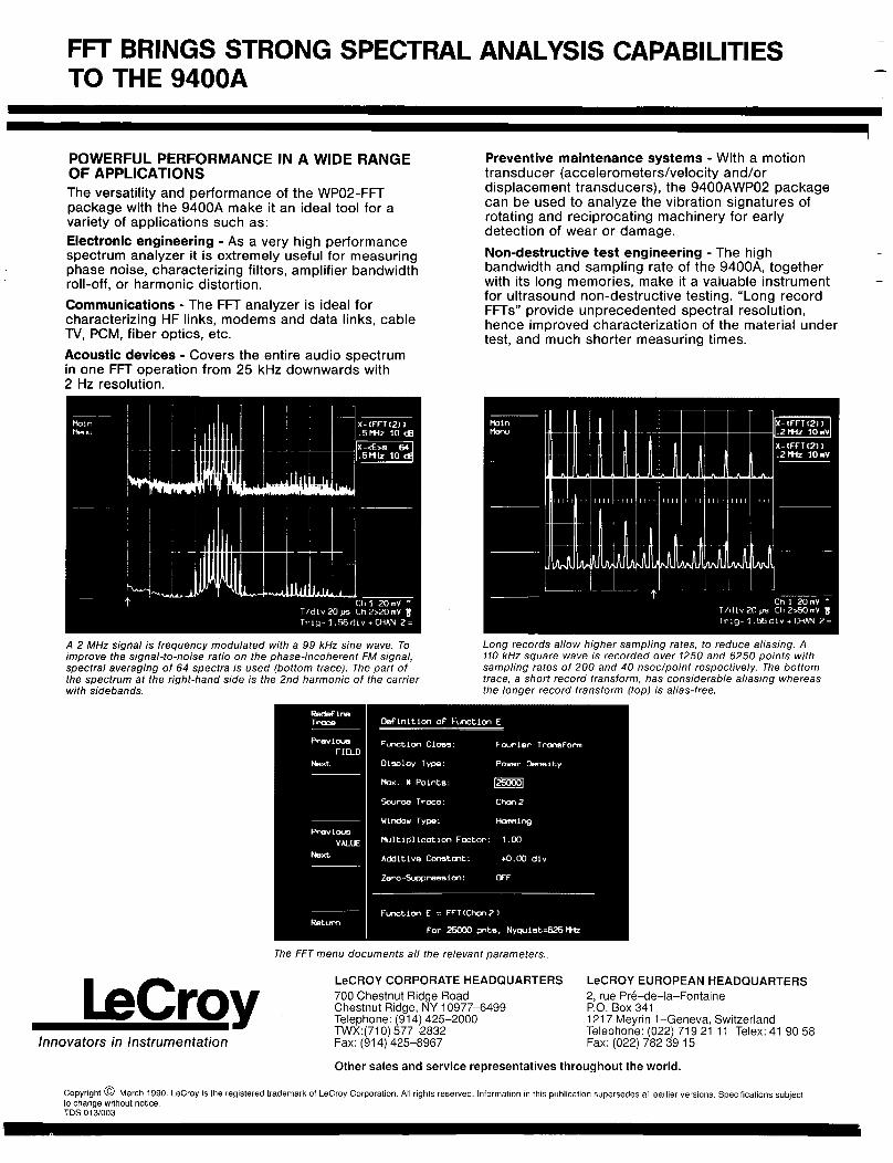
POWERFUL PERFORMANCE IN A WIDE RANGEOF APPLICATIONSThe versatility and performance of the WP02-FFTpackage with the 9400A make it an ideal tool for avariety of applications such as:Electronic engineering - As a very high performancespectrum analyzer it is extremely useful for measuringphase noise, characterizing filters, amplifier bandwidthroll-off, or harmonic distortion.Communications - The FFT analyzer is ideal forcharacterizing HF links, modems and data links, cableTV, PCM, fiber optics, etc.Acoustic devices - Covers the entire audio spectrumin one FFT operation from 25 kHz downwards with2 Hz resolution.
Preventive maintenance systems - With a motiontransducer (accelerometers/velocity and/ordisplacement transducers), the 9400AWP02 packagecan be used to analyze the vibration signatures ofrotating and reciprocating machinery for earlydetection of wear or damage.Non-destructive test engineering - The highbandwidth and sampling rate of the 9400A, togetherwith its long memories, make it a valuable instrumentfor ultrasound non-destructive testing. "Long recordFFTs" provide unprecedented spectral resolution,hence improved characterization of the material undertest, and much shorter measuring times.
X- (FFT (2)).2MHz 10mY
Ch 1 20 mV ~T/dry 20 ~s Ch 2>~] mVTrlg- 1.56 dLv + CHAN 2 =
A 2 MHz signal is frequency modulated with a 99 kHz sine wave. Toimprove the signal-to-noise ratio on the phase-incoherent FM signal,spectral averaging of 64 spectra is used (bottom trace). The part the spectrum at the right-hand side is the 2nd harmonic of the carrierwith sidebands.
Long records allow higher sampling rates, to reduce aliasing. A110 kHz square wave is recorded over 1250 and 6250 points withsampling rates of 200 and 40 nsec/point respectively. The bottomtrace, a short record transform, has considerable aliasing whereasthe longer record transform (top) is alias-free.
The FFT menu documents all the relevant parameters.
LeCroyInnovators in Instrumentation
LeCROY CORPORATE HEADQUARTERS700 Chestnut Ridge RoadChestnut Ridge, NY 10977-6499Telephone: (914) 425-2000TWX:(710) 577-2832Fax: (914) 425-8967
LeCROY EUROPEAN HEADQUARTERS2, rue [email protected]. Box 3411217 Meyrin 1-Geneva, SwitzerlandTelephone: (022) 719 21 11 Telex: 41 90 Fax: (022) 782 39
Other sales and service representatives throughout the world.
Copyright @ March 1990. LeCroy is the registered trademark of LeCroy Corporation. All rights reserved, information in this publication supersedes all earlier versions. Specifications subjectto change without notice.TOS 013/003

FUNCTIONAL DESCRIPTION
FOURIER PROCESSINGFourier processing is a mathematical techniquewhich permits a time-domain waveform to bedescribed in terms of frequency-domain magnitudeand phase, or real and imaginary spectra. In spec-tral analysis, a waveform can be sampled and digi-tized, then transformed by a discrete Fourier trans-form (DFT). Fast Fourier Transforms are a set ofalgorithms used to reduce the computation time(by better than a factor of 100 for a 1000 pointFFT) needed to evaluate a DFT. The principaladvantage of the FFT is the rapidity with which itcan analyze large quantities of waveform samples.In effect, using standard measurement techniques,it converts a time-domain instrument into digitalspectrum analyzer.
The WP02 Fast Fourier Processing Package enhancesthe outstanding features of the LeCroy 9400A DigitalOscilloscope. It provides high resolution, wide-bandspectrum analysis capabilities along with sophisticat-ed window functions and fast processing.
FFT AND THE LeCROY 9400A DIGITALOSCILLOSCOPEIn FFT mode, the 9400A provides measurement capa-bilities superior to those of common swept spectrumanalyzers.In particular, it is now possible to perform spectralanalysis on continuous and single events at an eco-nomic price. And it enables users to obtain time andfrequency values simultaneously and to comparephases of the various frequency components witheach other. Rather than the commonly used "power oftwo" record lengths the routines used in the WP02package feature decimal record lengths, which can beselected in a 1-2-5 order. Resulting spectra are there-fore also calibrated in convenient decimal Hertzvalues.
SPECIFICATIONS
The FFT’s digital nature ensures high accuracy, stabil-ity and repeatability. These are strongly supported bythe 9400A’s superb DC and dynamic accuracy speci-fications, such as standard +2%, optional 4-1%, DCaccuracy, high effective-bit count and increased reso-lution through signal averaging and dithering.With the 9400A, signals may be acquired and proces-sed simultaneously using Channels 1 and 2. This isparticularly useful when looking for common fre-quency-domain characteristics in both signals or forcharacterization of networks.
IMPROVED RESOLUTIONThe Fast Fourier Transform calculates equally-spacedfrequency components from DC to the full 9400Abandwidth. By lowering the sampling rate, it is pos-sible to make measurements with 1 milli-Hertz resolu-tion up to 12,5 Hz (Nyquist). By increasing the sam-pling rate to 5 gigasamples/sec (200 psec/point) Random Interleaved Sampling mode, the widest reso-lution becomes 50 MHz and the Nyquist frequency2.5 GHz... comfortably above the highest frequencycomponents recordable by the 9400A, thus virtuallyeliminating aliasing effects.
VERSATILE WINDOW FUNCTIONSThe WP02-FFT software provides a selection of win-dow functions, designed to minimize leakage and tomaximize spectral resolution of single and non-cyclicevents. These include the familiar rectangular orunmodified window typically used for transient events,the von Harm (Planning) and Hamming windows forcontinuous signals, and, in addition, Flattop andBlackman-Harris windows for more precise amplitude(power) measurements or strong suppression of sidelobes respectively.
Furthermore, user-defined window functions may beloaded onto the 9400A via the GPIB interface. Throughmultiplication, they modify the acquired signal follow-ed by FFT in an automated fashion.
VERTICAL ANALOG SECTIONInputs: two; BNC connectors.Sensitivity: 5 mV/div to 1 V/div at 50 £~ impedanceand 5 mV/div to 5 V/div at 1 M£) impedance; detentsat 1-2-5, variable 1:2.5.DC accuracy: standard <_ _+ 2%; optional _< _+ 1°.
MEMORIESAcquisition memory: 32K x 8 bits per channel(CH1 and CH2).Reference memory: 32K x 16 bits per referencememory (C and D).Function memory: 32K x 16 bits per function memory
Bandwidth (-3 dB):@ 50 (5: DC - 175 MHz at 10 mV/div, up to
225 MHz at 1 V/div;DC - 150 MHz at 5 mV/div.
@1 M~2 AC: 10 Hz-100 MHz typical@1 M~ DC: DC-100 MHz typical
Bandwidth limiter: 30 MHz (-3 dB).Input impedance: 1 M£~//50 pF and 50 £2characteristic.Maximum input: 250 V (DC + peak AC) at 1 M~ 5 V DC (500 mW) or 4- 10 V peak AC at 50 ~2.Offset: _+ 8 divisions in 0.04-division increments.
(E and F).The content of the acquisition and function memoriescan be stored in reference memories C and D.Record length selection for FFTFunction memories E and F only: 50-25000 datapoints in 9 steps in 1-2-5 sequence. Record lengthsare selected by decimation after signal acquisition.This implies that the Nyquist criterion can be adjustedand optimized after signal acquisition and prior to FFTexecution.

Blackman-Harris
REMOTE CONTROL
All front-panel controls and WP01 and WP02processing functions are fully programmable via the9400A GPIB and RS-232-C interfaces. SimpleEnglish-like mnemonics are used.
STORED FRONT PANELS
Up to 7 front-panel setups, including WP01 and WP02menu settings can be stored and recalled by themenu buttons at the left side of the 9400A screen.
WP02-FFT INSTALLATION
A WP02-FFT package may be retrofitted to a LeCroy9400A Digital Oscilloscope. The WP01 SignalProcessing hardware and software is a prerequisitefor installation of WP02.
Flattop
Hamming
von Hann (Hanning)
The sum of two 1 V p-p sinusoids of 500 kHz and 527.5 kHz isdigitized over 2,500 points and transformed to the frequency domain.4 different window functions are applied to indicate their effect onleakage suppression and spectral resolution. The vertical scale factoris 10 dB/div, 80 dBm full scale.
Long records give wide frequency span. FFT of 1000 Hz sine-amplitude modulated square wave, recorded over 25,000 points,shows harmonics up to 25 kHz. Expansion shows sidebands at 10 Hzand -30.1 dB.
ORDERING INFORMATION
Oscilloscope and Options
Code Description9400A Digital Oscilloscope9400AOP01 High-precision option (+_ 1% DC accuracy)9400AWP01Waveform processing option9400AWP02 Fast Fourier processing option (requires
9400AWP01 )9400AMS01 Mass storage and remote control package,
including an IBM lap-top controller, interface,cables and software
9400AIM01 GPIB interface for IBM-PCC computers
Oscilloscope AccessoriesOM9400A Operator’s ManualSM9400A Service ManualCA9001 Camera (using Polaroid film) and HoodCA9002 Camera adapter (35 mm) with HoodCS9400 Certified CalibrationDP9001 Digital Plotter, 8-pen A4 sizeOC9001 Oscilloscope CartRM9400 Adapter Kit for Rack MountingSG9001 High-voltage protectorTC9001 Transit CaseTC9002 Protective Cover

FREQUENCYFrequency range: DC to > 175 MHz.Frequency resolution: 1 mHz to 50 MHz.Nyquist frequency range: 25 mHz to 2.5 GHz.Frequency scale factors; 5 mHz/div to 500 MHz/div in1-2-5 sequence.Frequency accuracy: 0.008% at center lobe.Horizontal expansion: up to 100 times.Cursors: Differential (arrows) and absolute (crosshair)provide frequency and related amplitude measurements.AMPLITUDE AND PHASEGeneralAmplitude accuracy: see window functions table below.Signal overflow: A warning indication is provided atthe top of the 9400A display when the input signalexceeds the ADC range.DC suppression: selected via the menu (ON/OFF),removes DC component prior to FFT execution.Cursors: Horizontal bars provide differential amplitudemeasurements.Number of traces: Time domain and frequencydomain data can be displayed simultaneously (up to4 traces).Spectrum Display Formats and ScalingReal spectrum, in V/div, zero base line at 0 div (centerof screen).Imaginary spectrum in V/div, zero base line at 0 div.Power spectrum in dBm.Power spectral density in dBm.Frequency Domain Averaging up to 200 spectra forpower, PSD or magnitude.Log display applies to power and PSD spectra in
10, 5, 2 or 1 dB/div; 80 clB display range.Markers at left edge of screen give absolute dBmreference (0 dBm is 1 mW into 50 ~).
PhasePhase range: + 180 degrees to - 180 degrees.Phase accuracy: ___ 5 degrees.Phase scale factor: 50 degrees/div.Zero base line: 0 div (center of screen).Calibrated Vertical ExpansionAll spectra formats, up to 10 times, in 1-2-5 sequence.Window FunctionsSelected in menu: Rectangular, von Hann (Hanning),Hamming, Flattop, Blackman-Harris and userdefinable. The table below gives filter pass bandshape and resolution:
FILTER PASS BAND AND RESOLUTION
WindowtypeRec-tangularvon HannHammingFlattopBlackman.Harris
Filter band.width at Highest Scallop Noise band-
6dB side lobe Loss width(freq. bins) (dB) (dB at bin) (freq. bins)
1.21 --13 3.92 1.02.00 --32 1.42 1.51.81 --43 1.78 1.361.78 --44 0.01 2.961.81 --67 1.13 1.71
DefinitionsFilter bandwidth at -6dB characterizes the frequencyresolution of the filter.Highest side lobe indicates the reduction in leakageof signal components into neighboring frequency bins.Scallop loss gives amplitude accuracy of themagnitude spectrum.Noise bandwidth is the bandwidth of an equivalentrectangular filter.
FFT EXECUTION TIME
FFT execution times, including window calculationsand display generation, are provided in the graphbelow:
/
//
/
//
jJm
z.c
,_0
u_
vLU
5-
XL~
50 125 250 625 1250 2500 6250 12500 25000
RECORD LENGTH (Points)
WP01 SIGNAL AVERAGING/ARITHMETICPROCESSING (Prerequisite for WP02)
Summation averaging: 10-1,000,000 signals.Continuous averaging: infinite number of signals,weighting factors 1, 3, 7, 15, 63, 31,127.Waveform arithmetic: +, -, *, +.Waveform functions: integration, differentiation,square, square root, negation (inversion).Smoothing: 1-, 3-, 5-, 7-, 9-point filters.Extrema: records extreme values (envelopes) over programmable number of sweeps.
CHAINING OF OPERATIONSTwo functions can be automatically chained usingfunctions E and F.Examples: fnE = CH1 * CH2
fnF = FFT of fnEfnE = FFT of CH1fnF = Integral fnE
Manual chaining using memories C and D forintermediate results may continue indefinitely.

SECTION I
GENERAL INFORMATION
I.I Warranty
LeCroy warrants its oscilloscope products to operate withinspecifications under normal use, and services them for a period of twoyears from the date of shipment. Spares, replacement parts and repairsare warranted for 90 days. Software is thoroughly tested but issupplied "as is" with no warranty of any kind covering detailedperformance. Accessory products not manufactured by LeCroy are coveredsolely by the warranty of the original equipment manufacturer.
In exercising this warranty, LeCroy will repair or, at its option,replace any product returned to the Customer Service Department or anauthorized service facility within the warranty period, provided thatthe warrantor’s examination discloses that the product is defective dueto workmanship or materials, and that the defect has not been caused bymisuse, neglect, accident or abnormal conditions or operation.
The purchaser is responsible for the transportation and insurancecharges arising from the return of products to the servicing facility.LeCroy will return all in-warranty products with transportationprepaid.
This warranty is in lieu of all other warranties, expressed or implied,including but not limited to any implied warranty of merchantability,fitness, or adequacy for any particular purpose or use. LeCroy shallnot be liable for any special, incidental, or consequential damages,whether in contract, or otherwise.
1.2 Assistance and Maintenance Agreements
Answers to questions concerning installation, calibration, and use ofLeCroy equipment are available from the Customer Service Department,700 Chestnut Ridge Road, Chestnut Ridge, New York 10977-6499, U.S.A.,(914)578-6097, and I01 Route du Nant drAvril, 1217 Meyrin i, Geneva,Switzerland, (41)22/782-33-55, or your local field engineering office.
LeCroy offers a selection of customer support services. For example,maintenance agreements provide extended warranty and allow the customerto budget maintenance costs after the initial two year warranty hasexpired. Other services requested by the customer such as installation,training, on-site repair, and addition of engineering improvements aremade available through specific Supplemental Support Agreements.
I-iGeneral Information

1.3 Documentation Discrepancies
LeCroy is committed to providing state-of-the-art instrumentation andis continually refining and improving the performance of its products.While physical modifications can be implemented quite rapidly, thecorrected documentation frequently requires more time to produce.Consequently, this manual may not agree in every detail with theaccompanying product. There may be small discrepancies in the values ofcomponents for the purposes of pulse shape, timing, offset, etc., and,occasionally, minor logic changes. Where any such inconsistenciesexist, please be assured that the unit is correct and incorporates themost up-to-date circuitry.
1.4 Service Procedure
Products requiring maintenance should be returned to the CustomerService Department or authorized service facility. If under warranty,LeCroy will repair or replace the product at no charge. The purchaseris only responsible for the transportation charges arising from returnof the goods to the service facility.
For all LeCroy products in need of repair after the warranty period,the customer must provide a Purchase Order Number before any equipmentwhich does not operate correctly can be repaired or replaced. Thecustomer will be billed for the parts and labor for the repair as wellas for shipping.
1.5 Return Procedure
To determine your nearest authorized service facility, contact thefactory or your field office. All products returned for repair shouldbe identified by the model and serial numbers and include a descriptionof the defect or failure, name and phone number of the user, and, inthe case of products returned to the factory, a Return AuthorizationNumber (RAN). The RAN may be obtained by contacting the CustomerServices Department in New York on 914-578-6059, in Geneva on(022) 782-33-55 or your nearest sales office.
Return shipments should be made prepaid. LeCroy will not accept C.O.D.or Collect Return Shipments. Air-freight is generally recommended.Wherever possible, the original shipping carton should be used. If asubstitute carton is used it should be rigid, and should be packed suchthat the product is surrounded with a minimum of four inches ofexcelsior or a similar shock-absorbing material. In addressing theshipment, it is important that the Return Authorization Number bedisplayed on the outside of the container to ensure its prompt routingto the proper department within LeCroy.
1-2General Information

1.6 Initial Inspection
It is recommended that the shipment be thoroughly inspected immediatelyupon delivery to the purchaser. All material in the container should bechecked against the enclosed Packing List. LeCroy cannot acceptresponsibility for shortages in comparison with the Packing List unlessnotified promptly. If the shipment is damaged in any way, pleasecontact the factory or local field office immediately.
1-3General Information


SECTION 2
PRODUCT DESCRIPTION
2.1 Introduction
The LeCroy 9400A is a high-performance digital oscilloscope suited toresearch and to test and measurement applications. It is used tocapture, analyze, display and archive electrical waveforms in fieldssuch as electronic engineering, physics research, automated testing andmeasurement, telecommunications, electromagnetic pulse and interferencemeasurement, LIDAR technology and ultrasonics research.
2.2 9400A Architecture
The 9400A has been built around the powerful 68000 microprocessor whichis used by the unit to perform computations and control oscilloscopeoperation.
Att~uator Amplifier 5omple 4. AOC Acqulsition Processor +hold memory interfaces
ACOffsel Gain ....
r15112C ""
!
9400A BLOCK DIAGRAM
Figure 2.1
Product Description2-1
All front panel rotary knobs and push buttons are constantly monitoredby the internal processor, and front panel setups are rapidlyreconfigured via the unit’s internal 16-bit bus. Data are quicklyprocessed according to the selected front panel setups, and aretransferred to the acquisition memory for direct waveform display orstored in the 9400A’s reference memories.
The 68000 controls the unit’s two RS-232-C ports which are used todirectly interface the 9400A to a digital plotter, remote terminal orother slow-speed device and also controls GPIB (IEEE-488) operationwhen the 9400A is equipped with the I/O option, OP02.
2.3 ADCs and Memories
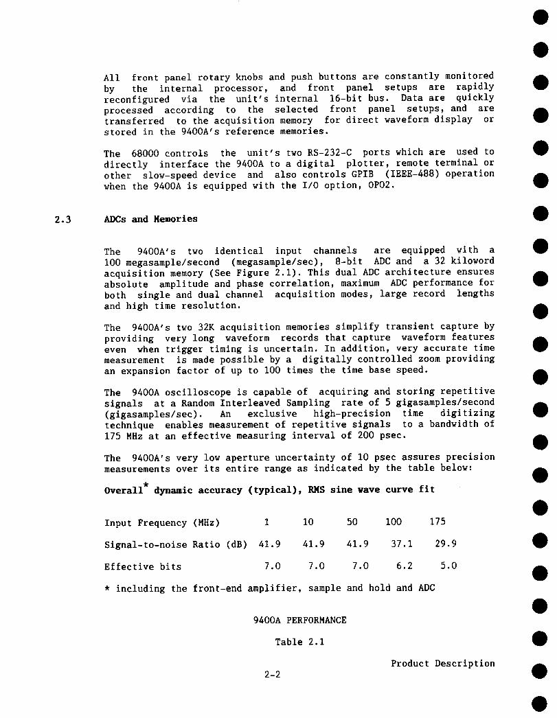
The 9400A’s two identical input channels are equipped with aI00 megasample/second (megasample/sec), 8-bit ADC and a 32 kilowordacquisition memory (See Figure 2.1). This dual ADC architecture ensuresabsolute amplitude and phase correlation, maximum ADC performance forboth single and dual channel acquisition modes, large record lengthsand high time resolution.
The 9400A’s two 32K acquisition memories simplify transient capture byproviding very long waveform records that capture waveform featureseven when trigger timing is uncertain. In addition, very accurate timemeasurement is made possible by a digitally controlled zoom providingan expansion factor of up to I00 times the time base speed.
The 9400A oscilloscope is capable of acquiring and storing repetitivesignals at a Random Interleaved Sampling rate of 5 gigasamples/second(gigasamples/sec). An exclusive high-precision time digitizingtechnique enables measurement of repetitive signals to a bandwidth of175 MHz at an effective measuring interval of 200 psec.
The 9400A’s very low aperture uncertainty of 10 psec assures precisionmeasurements over its entire range as indicated by the table below:
Overall* dynamic accuracy (typical), RMS sine wave curve fit
Input Frequency (MHz) 1 10 50 100 175
Signal-to-noise Ratio (dB) 41.9 41.9 41.9 37.1 29.9
Effective bits 7.0 7.0 7.0 6.2 5.0
* including the front-end amplifier, sample and hold and ADC
9400A PERFORMANCE
Table 2.1
2-2Product Description
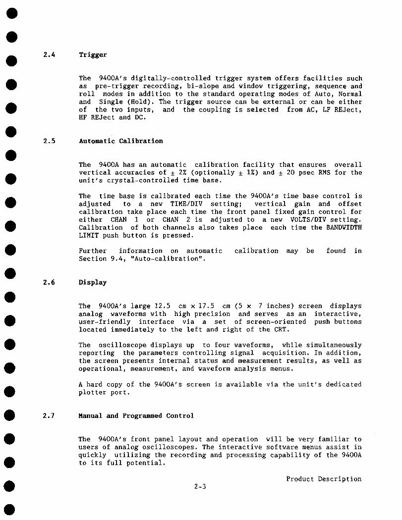
2.4 Trigger
The 9400A’s digitally-controlled trigger system offers facilities suchas pre-trigger recording, bi-slope and window triggering, sequence androll modes in addition to the standard operating modes of Auto, Normaland Single (Hold). The trigger source can be external or can be eitherof the two inputs, and the coupling is selected from AC, LF REJect,HF REJect and DC.
2.5 Automatic Calibration
The 9400A has an automatic calibration facility that ensures overallvertical accuracies of ± 2% (optionally ± 1%) and ± 20 psec RMS for theunit’s crystal-controlled time base.
The time base is calibrated each time the 9400A’s time base control isadjusted to a new TIME/DIV setting; vertical gain and offsetcalibration take place each time the front panel fixed gain control foreither CHAN i or CHAN 2 is adjusted to a new VOLTS/DIV setting.Calibration of both channels also takes place each time the BANDWIDTHLIMIT push button is pressed.
Further information on automaticSection 9.4, "Auto-calibration".
calibration may be found in
2.6 Display
The 9400A’s large 12.5 cm x 17.5 cm (5 x 7 inches) screen displaysanalog waveforms with high precision and serves as an interactive,user-friendly interface via a set of screen-oriented push buttonslocated immediately to the left and right of the CRT.
The oscilloscope displays up to four waveforms, while simultaneouslyreporting the parameters controlling signal acquisition. In addition,the screen presents internal status and measurement results, as well asoperational, measurement, and waveform analysis menus.
A hard copy of the 9400A’s screen is available via the unit’s dedicatedplotter port.
2.7 Manual and Programmed Control
The 9400A’s front panel layout and operation will be very familiar tousers of analog oscilloscopes. The interactive software menus assist inquickly utilizing the recording and processing capability of the 9400Ato its full potential.
2-3Product Description

The 9400A has also been designed for remote control operation inautomated testing and computer aided measurement applications. Theentire measurement process, including dynamic modification of frontpanel settings and display organization, can be controlled via the rearpanel RS-232-C and optional GPIB (IEEE-488) ports. GPIB controlenables direct interfacing between the 9400A and a host computer atdata transfer rates of up to 400 kilobytes/sec.
The LeCroy 9400A is capable of storing up to seven front panel setupswhich may be recalled either manually or by remote control, thusensuring rapid oscilloscope front panel configuration. When the poweris switched on, the 9400A’s front panel settings are the same as whenit was last used.
2-4Product Description

SECTION 3
INSTALLATION
3.1 Safety Information
The 9400A has been designed to operate from a single-phase power sourcewith one of the current-carrying conductors (neutral conductor) ground (earth) potential. Operation from power sources in which bothcurrent-carrying conductors are live with respect to ground (such asphase-to-phase on a tri-phase system) is not recommended, as the 9400Ais equipped with over-current protection for one mains conductor only.
The 9400A is provided with a three-wire electrical cord containing athree-terminal polarized plug for mains voltage and safety groundconnection. The plug’s ground terminal is connected directly to theframe of the unit. For adequate protection against electrical hazard,this plug must be inserted into a mating outlet containing a safetyground contact.
3.2 Operating Voltage
Prior to powering up the unit, make certain that the mains voltage foryour area corresponds to the mains voltage value appearing in thewindow of the selector box at the rear of the 9400A.
The operating voltage for the 9400A is either 115 V or 220 V at 48 to62 Hz. Switching from one mains voltage to another is not possible. Ifthe mains voltage appearing in the window differs from that used inyour area contact the nearest LeCroy sales office or distributor.
*CAUTION*
If a 9400A set for 115 V is plugged into a 220 V power source, severedamage can occur. Before powering up the unit, ensure that the corectline voltage has been set.
3-iInstallation

3.3 Switching on the 9400A
Switch on the 9400A by setting the POWER switch (26) to the
position.An auto-calibration takes place and the grid is displayedafter approximately 15 seconds.
Note that the 9400A is reset to the configuration it was in prior beingto switched off.
3-1Installation

SECTION 4
DISPLAY LAYOUT
The 9400A’s CRT area is divided between the centrally located grid andsix other fields. Traces from the acquisition or reference memories aredisplayed on the grid. A dual grid system is also available by pressingpush button 14 (see Figure 1.1). The six fields are used to displaysuch information as interactive menu queries and responses, currentacquisition parameters, relative and absolute time and voltagemeasurements, and messages to assist the user.
°.
..
DISPLAY LAYOUT
Figure 4.1
4.1 Menu Field (I)
This field is divided into nine sub-fields associated with menu keys2-10. Each field may display the name of a menu or perform an operationwhen the related menu key is pressed. The lowest field and relatedReturn push button (i0) are used to restore the higher menu level.
4-1
Display Layout
4.2 Time and Frequency Field (II)
When the Marker cursor is activated by pressing push button (18), thisfield displays the time difference between the Marker cross-hair andthe point of triggering (common for all displayed traces).
When the Time cursors are activated by pressing push button (17), tworeadings are indicated. The left-hand reading indicates the timeinterval between the Reference and Difference arrowhead cursors, whilethe right-hand reading indicates the frequency corresponding to 1/(Timeinterval).
Trigger Delay Field (III)
This field indicates one of the two trigger delay modes. In thepre-trigger mode, an upward-pointing arrow appears below the bottomline of the trace display grid, as shown in Figure 4.1. It isadjustable from 0 to 10 divisions, corresponding to a 0 to 100Zpre-trigger setting. In the post-trigger mode, this arrow is replacedby a leftward-pointing arrow next to the post-trigger indication (indecimal fractions of a second) at the bottom of the grid. The maximumpost-trigger setting corresponds to 10000 screen divisions.
4.4 Abridged Front Panel Status Field (IV)
This is a short-form display of the data acquisition parameters, and isupdated whenever the 9400A’s front panel controls are manipulated. Thisfield indicates vertical sensitivities, input couplings, time base andtrigger conditions.
See Section 5 for a detailed list of front panel parameters (includingthe absolute value of input offset).
4.5 Displayed Trace Field (V)
The Displayed Trace field is associated with push buttons 45-50. Thedata displayed in this field are the identity of the displayed trace,and the current time base and sensitivity settings for the acquiredsignal, as well as an indication of the position of the VAR sensitivityvernier (28). The symbol ">" appears when the vernier is not in thedetent position (i.e. not in the fully clockwise position). WheneverMeasurement Cursors (16, 17, 18) are activated, absolute or relativewaveform voltage data are displayed in this field.
A frame formed around one of the upper six signal sources in theDisplayed Trace field indicates which of the traces is to be acted uponduring manipulation of the various display controls ((39) through (43).
Display Layout4-2

4.6 Message Field (VI)
Messages appearing in field (Vl) indicate the 9400A’s currentacquisition status or report improper manipulation of the front panelcontrols. The following figure illustrates a typical message displayedin the Message field.
Channel 15~e 20mV
Channel 25~ .5 V
Ch~ 20mVT/dlv 5~m 012 .5 V ~Trig S.O8dtv+CHAN ~
EXAMPLE of MESSAGE FIELD DISPLAY
Figure 4.2
********
*NOTE*********
In the following sections, Roman numerals in parentheses refer to thedisplay field numbering scheme in Figure 4.1. Arabic numerals relate tothe numbering scheme used to refer to front and rear panel controls andconnectors in Figures i.I and 1.2.
4-3
Display Layout

SECTION 5
MANUAL OPERATION
5.1 Front-Pmlel Controls
5.1.1 Vertical
Input Connectors (21) - BNC type connectors are used for both CHAN and CHAN 2 signal inputs as well as the external trigger connector.The maximum permissible input voltage is 250 V (DC + peak AC).
Signal Coupling and Input Impedance (22) - Selects the method used couple a signal to the vertical amplifier input.
Possible selections: AC, GND, or DC with I M~ impedanceDC with 50 ~ impedance
In the AC position, signals are coupled capacitively, thus blocking theinput signal’s DC component and limiting the lower signal frequenciesto < i0 Hz.
In the DC position, all signal frequency components are allowed to passthrough, and the input impedance may be chosen to be I M~ or 50 ~. Theuser should note that with I M~ input impedance the bandwidth islimited to I00 MHz. The maximum dissipation into 50 ~ is 0.5 W, andsignals will automatically be disconnected whenever this occurs. Awarning LED (OVERLD) lights when an overload condition is detected. Theinput coupling LED (22) is simultaneously switched to GND. The overloadcondition is reset by removing the signal from the input and selectinga 50 ~ input impedance again.
VOLTS/DIV (27) - Selects the vertical sensitivity factor in a 1-2-5sequence. The sensitivity range is from 5 mV to 5 V/div at I M~ inputimpedance and from 5 mV to I V/div at 50 ~ impedance (when the VARvernier (28) is in the detent position, i.e. turned fully clockwise).
5-1Manual Operation

Menu
C~’1 5mVllT/d:l.v .2jJ Ch2 .5 V -Trlg .2O V - ~ =
DISPLAY of VERTICAL SENSITIVITY PARAMETERSin the ABRIDGED PANEL STATUS FIELD
Figure 5.1
The VOLTS/DIV setting for CHAN 1 and CHAN 2 is displayed, along withsignal input coupling and various other data, in the Abridged PanelStatus Field (IV), see Figure 4.1. It may be modified either manuallyor via remote control, and is immediately updated.
Whereas acquisition control settings displayed in the Abridged PanelStatus Field (IV) are immediately updated upon manual or remote modifi-cations of the VOLTS/DIV or TIME/DIV settings, the control settings inthe Displayed Trace field (V), corresponding to the conditions underwhich the waveform was stored, are updated with every trigger.
I:h.....d. t.IJ~ IluNChmrmL 2.e~, v
.~L V~T/dlv’JiOn.. Oh2 .2 Y ,,Trl~i- .20V - EXT -
SENSITIVITY DATA DISPLAYED in the ABRIDGED PANELSTATUS FIELD and in the DISPLAYED TRACE FIELD
Figure 5.2
Manual Operation5-2

VAR (28) - Verniers provide continuously variable sensitivity withinthe VOLTS/DIV settings and extend the maximum vertical sensitivityfactor to up to 12.5 V/div. Variable sensitivity settings are indicatedby the ">" symbol in the lower portion of the Abridged Front PanelStatus field and the calibrated value appears in the Total V/div fieldof the Panel Status menu (See Section 5.2.2). (Minimum sensitivity achieved by rotating the vernier counter-clockwise.)
VERTICAL OFFSET (32) - This control vertically positions the displayedtrace. The maximum offset is ± 1 grid height (± 8 divisions) from thecenter of the screen, and is manually adjustable (or programmable) 0.04 division increments. A pair of upward- or downward-pointingdouble-shaft arrows indicates when the trace has been positionedoutside the grid, as shown in Figure 5.3.
ir w
UPWARD and DOWNWARD POINTING, DOUBLE SHAFT ARROWSINDICATING THAT CHANNEL 1 and 2 ARE OFF SCREEN
Figure 5.3
PROBES - Two Model P9010 passive probes are supplied with the 9400A.These probes have I0 M~ input impedance and 6 pF capacitance. Thesystem bandwidth with P9010 probes is DC to I00 MHz in 1M~ DCcoupling, and < I0 Hz to I00 MHz in AC coupling. Active FET probes(Tektronix models P6201, P6202a and P6230) may be powered via probepower connectors on the rear panel.
Manual Operation5-3
PROBE CALIBRATION (19, 20) Tocal ibrate the P9010 Prob e, conn ect itto the CHAN 1 or CHAN 2 BNC connector (21). Connect the probe’sgrounding alligator clip to the front panel ground lug (20) of theoscilloscope and the tip to lug (19).
Adjust the 9400A’s front panel controls as described in Section 8.1. Incase of over- or undershooting of the displayed signal, it is possibleto adjust the P9010 Probe by inserting the small screwdriver, suppliedwith the probe package, into the trimmer on the probe’s barrel andturning it clockwise or counter-clockwise to achieve an optimal squarewave contour.
BANDWIDTH LIMIT (50) Byset ting the BAND~rlDTH LIMI T butt on to O N t hebandwidth can be reduced from 175 MHz to 30 MHz (-3 dB). Bandwidthlimiting may be useful in reducing signal and system noise orpreventing high-frequency aliasing for single-shot events at time basesbelow 50 ~sec/division.
5.1.2 Time Base
TIME/DIVISION (36) Th is co ntrol se lects th e ti me pe r di vision in a1-2-5 sequence from 2 nsec to 100 sec. The time base is displayed inthe Abridged Panel Status field (IV) as well as in the Displayed Tracefield (V). The time bas~ is crystal-controlled and features an overallaccuracy better than I0-~.
SAMPLING MODES
Three sampling modes are possible with the 9400A depending on thetime-base setting selected by the user. They are:
* Random Interleaved Sampling (RIS)* Single Shot (SS)* Roll Mode
Random Interleaved Sampling (RIS)
At time-base settings from 2 to 20 nsec/div, the 9400A automaticallyuses the RIS mode for signal acquisition. Repetitive waveforms and astable trigger are required. Waveforms can be digitized with samplingintervals as small as 200 psec for an equivalent sampling rate of upto 5 gigasamples/sec.
5-4Manual Operation
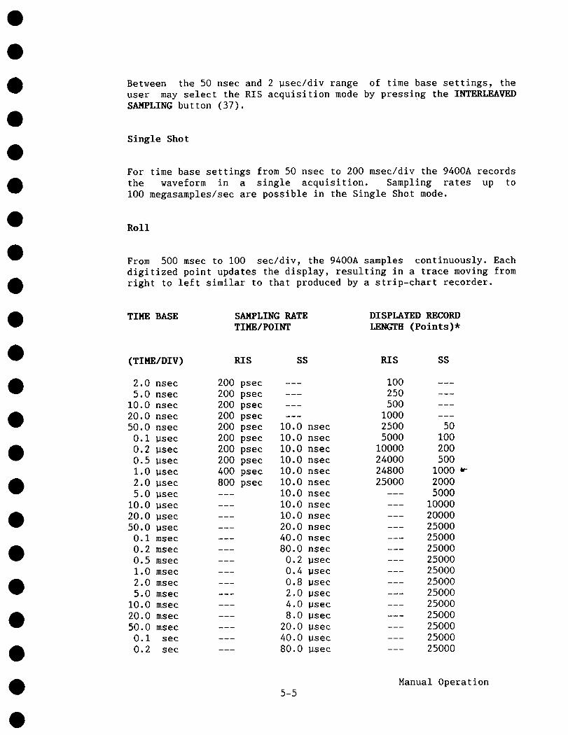
Between the 50 nsec and 2 psec/div range of time base settings, theuser may select the RIS acquisition mode by pressing the INTERLEAVEDSAMPLING button (37).
Single Shot
For time base settings from 50 nsec to 200 msec/div the 9400A recordsthe waveform in a single acquisition. Sampling rates up toi00 megasamples/sec are possible in the Single Shot mode.
Roll
From 500 msec to I00 sec/div, the 9400A samples continuously. Eachdigitized point updates the display, resulting in a trace moving fromright to left similar to that produced by a strip-chart recorder.
TIME BASE SAMPLING RATETIME/POINT
DISPLAYED RECORDLENGTH (Points)*
(TIME/DIV) RIS SS RIS SS
2.0 nsec 200 psec I005.0 nsec 200 psec 250 ---
i0.0 nsec 200 psec 50020.0 nsec 200 psec I00050.0 nsec 200 psec I0.0 nsec 2500 50
0.I ~sec 200 psec I0.0 nsec 5000 I000.2 ~sec 200 psec i0.0 nsec 10000 2000.5 psec 200 psec i0.0 nsec 24000 5001.0 psec 400 psec I0.0 nsec 24800 i0002.0 ~sec 800 psec I0.0 nsec 25000 20005.0 psec I0.0 nsec 5000
I0.0 psec i0.0 nsec i000020.0 psec I0.0 nsec 2000050.0 Bsec 20.0 nsec 25000
0.i msec 40.0 nsec 250000.2 msec 80.0 nsec 250000.5 msec 0.2 psec 250001.0 msec 0.4 psec 250002.0 msec 0.8 ~sec 250005.0 msec 2.0 psec 25000
I0.0 msec 4.0 Hsec 2500020.0 msec 8.0 psec 2500050.0 msec 20.0 ~sec 25000
0.I sec 40.0 psec 250000.2 sec 80.0 ~sec 25000
5-5Manual Operation

TIHE BASE SA}4PLING RATETIME/POINT
DISPLAYED RECORDI.RNCTH (Points)*
(TIME/DIV) RIS SS RIS SS
ROLL NODE
0.5 sec 0.2 msec --- 25000
1.0 sec 0.4 msec --- 25000
2.0 sec 0.8 msec --- 25000
5.0 sec 2.0 msec 25000
I0.0 sec 4.0 msec 25000
20.0 sec 8.0 msec 25000
50.0 sec 20.0 msec 25000
I00.0 sec --- 40.0 msec 25000
Note: When the 9400A is remotely read out, the entire memory content of32,000 words is available at all time base speeds for single shot androll modes. 24,000 samples are available for all RIS settings except atI and 2 psec/div, when 24,800 and 25,000 samples respectively areavailable.
LIST of SAMPLING MODES, SAMPLING RATE,and DISPLAYED RECORD LENGTH
Table 5.1
5.1.3 Trigger
EXTERNAL Trigger Input (24) - This BNC connector input accepts external trigger signal of up to 250 V (DC + peak AC). Input impedanceis 1M~ in parallel with < 30 pF. The triggering frequency is >200 MHz.
Trigger SOURCE (23) - Selects the trigger signal source as follows:
CHAN 1 - Selects the Channel i input signal.
CHAN 2 - Selects the Channel 2 input signal.
LINE - Selects the line voltage powering the oscilloscope in orderto provide a stable display of signals synchronous with the powerline.
5-6Manual Operation
EXT - With the Trigger SOURCE set to EXT, a signal applied to theBNC connector labeled EXTERNAL can be used to trigger the scopewithin a range of ± 2 V.
EXT/IO - With the Trigger SOURCE set to EXT/10, a signal appliedto the BNC connector labeled EXTERNAL, can be used to trigger thescope within a range of ± 20 V.
Trigger COUPLING (30) - Selects the type of signal coupling to thetrigger circuit:
AC Trigger - Signals are capacitively coupled; DC levels arerejected and frequencies below 60 Hz are attenuated.
LF REJ - Signals are coupled via a capacitive high-pass filternetwork. DC is rejected and signal frequencies below 50 kHz areattenuated. The LF REJ trigger mode is used whenever triggering onhigh frequencies is desired.
BF RBJ - Signals are DC-coupled to the trigger circuit and alow-pass filter network attenuates frequencies above 50 kHz. TheHF REJ trigger mode is used when triggering on low frequencies isdesired.
DC - All of the signal’s frequency components are coupled to thetrigger circuit. This coupling mode is used in the case of highfrequency bursts, or where the use of AC coupling would shift theeffective trigger level.
Trigger LEVBL (33) - Adjusts the level of the signal required generate a trigger.
The trigger range is as follows:
± 5 screen divisions - with CHAN 1 or CHAN 2 as trigger source
None (zero-crossing) with LINE as trigger source
± 2 V with EXT as trigger source
± 20 V with EXT/IO as trigger source
SLOPE (25) Se lects th e si gnal ed ge us ed to act ivate thecircuit.
POS - Requires a positive-going edge of the trigger signal.
NEG - Requires a negative-going edge.
trigger
5-7Manual Operation
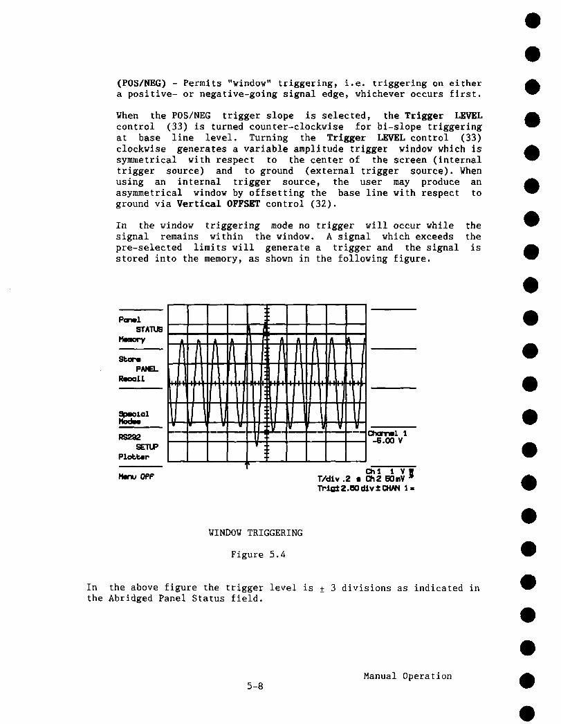
(POS/NEG) - Permits "window" triggering, i.e. triggering on eithera positive- or negative-going signal edge, whichever occurs first.
When the POS/NEG trigger slope is selected, the Trigger LEVELcontrol (33) is turned counter-clOckwise for bi-slope triggeringat base line level. Turning the Trigger LEVEL control (33)clockwise generates a variable amplitude trigger window which issymmetrical with respect to the center of the screen (internaltrigger source) and to ground (external trigger source). Whenusing an internal trigger source, the user may produce anasymmetrical window by offsetting the base line with respect toground via Vertical OFFSET control (32).
In the window triggering mode no trigger will occur while thesignal remains within the window. A signal which exceeds thepre-selected limits will generate a trigger and the signal isstored into the memory, as shown in the following figure.
ParmlSTATUS
¯ M
WINDOW TRIGGERING
Figure 5.4
In the above figure the trigger level is ± 3 divisions as indicated inthe Abridged Panel Status field.
Manual Operation5-8

Trigger MODE (29) - Selects the mode of trigger operation as follows:
SINGLE (HOLD) - Selected using the lower button (29).
In this mode the 9400A digitizes until a valid trigger isreceived. After the waveform has been acquired and displayed, nofurther signals can be acquired until the SINGLE (HOLD) button hasbeen pressed again to re-arm the trigger circuit in preparationfor the next trigger signal. This type of acquisition provides asimple means of recording a wide variety of transient events.
When the 9400A is in the Random Interleaved Sampling (RIS) mode, sufficient number of triggers must be obtained to completewaveform reconstruction, after which the waveform will bedisplayed. No further signals can be acquired until the SINGLE(HOLD) button has been pressed again.
When the 9400A is in the Roll mode (~ 500 msec/div), pressing theSINGLE (HOLD) button causes data acquisition to immediately haltand the display to freeze.
NORM - Selected using button (29).
When in the normal (NORM) trigger mode, the 9400A continuouslydigitizes the input signal. Whenever a valid trigger is received,the acquired waveform is displayed on the CRT, digitization startsagain and the trigger circuit is re-armed. If no subsequenttrigger is received within 2 seconds, previously acquiredwaveforms are erased from the screen. The absence of a validtrigger will thus result in a blank screen.
To retain the last acquired waveform indefinitely in the NORMmode, the 9400A’s Auto-store feature is used. Auto-store can becalled via the Special Modes menu described in Section 5.2.5.
When the 9400A is in the RIS mode, a sufficient number (typically200) of valid triggers is required for each display of a completewaveform.
In the Roll mode (~ 500 msec/div), the 9400A samples the inputsignals continuously. Each point is immediately updated on thedisplay. This results in a trace which moves from right to leftacross the CRT. In the NORM mode, triggers are ignored. The onlyway to halt data acquisition is to select the SINGLE (HOLD) modeor switch the 9400A into AUTO mode and provide a trigger.
5-9Manual Operation
AUTO - Selected using button (29).
This mode resembles the NORM mode, except that it automaticallygenerates an internal trigger and forces a waveform to appear onthe screen whenever the selected trigger is not present for morethan 500 msec. When the 9400A auto-triggers, the display usuallymoves in time as the trigger is not time-correlated with the inputsignal.
Auto trigger can not be used when the 9400A is in the RIS mode.
When the 9400A is in the Roll mode (> 500 msec/div), it samplesinput signals continuously. In the AUTO mode any valid triggerwill halt data acquisition once the trigger delay requirementshave been satisfied.
SEO_NCE - Selected using the upper button (29).
Sequence triggering enables the 9400A’s acquisition memories to bepartitioned into up to 250 segments.
Possible settings are: 8, 15, 31, 62, 125, or 250 segments.
Waveform acquisition in SEONCE mode is particularly useful in thecase of short-lived or echoed signals, such as those typicallyencountered in RADAR, SONAR, LIDAR and NMR.
In this mode, the time base setting determines the total duration(TIME/DIV x I0) of each segment. Changing the number of requiredsegments does not change the time base; it only affects the numberof digitized points (record length) per segment. The number data points per division is shown in the Acquisition Parametersdisplay, called by pressing Panel STATUS button (2).
The display is only updated after a sufficient number of sweepshas been acquired. If less than the required number of triggers isavailable the SEQNCE acquisition may be aborted by pushing theSEQNCE button (29) again.
The 9400A then completes the missing sweeps by auto-triggering asufficient number of times while setting its input couplingtemporarily to GND. Thus the artificially completed sweeps willappear on the display as GND lines.
Manual Operation5-10

Number of Segments Points/Seg~nent
8 250115 200131 i00162 497
125 241250 I01
SEQUENCE TRIGGER MODENUMBER OF SEGMENTS VS. RECORD LENGTH (TIME BASE: 20 usec)
Table 5.2
Neither the CHAN 1 nor CHAN 2 display is updated when the 9400A isin the SINGLE or SEQNCE trigger mode, i.e. when no further dataare acquired. Vertical positioning of the displayed trace maynevertheless be modified via the OFFSET control (32). The VARvernier (28) also remains active. However, no other parametermodifications, such as vertical sensitivity or time changes, willalter the display of a currently acquired waveform in CHAN 1 orCHAN 2.
Of course, all parameters may be modified during this time bymanipulating the appropriate front panel controls, but suchmodification - indicated by parameter changes in the AbridgedFront Panel Status field (IV) - will only be used when acquiringthe next trace.
Whenever the 9400A is in the NORM or AUTO trigger mode, data arecontinuously acquired and the display rapidly updated. Allmodifications in acquisition parameters are thus followed quicklyby subsequent waveform acquisition which results in theirappearing to the user as changes to the CHAN 1 or CHAN 2 display.
TRIG’D and READY LEDs (31) - The TRIG’D LED indicates Whenever thedigitizing has stopped (normally after a valid trigger). The READY LEDindicates that the trigger circuit has been armed and the 9400A iscurrently digitizing input signals. Upon receiving a valid triggersignal, it will continue digitization until the trigger conditions havebeen satisfied and will then display the acquired waveform.
DELAY (34) - Adjusts the degree of pre- or post-trigger delay whenrecording signals in the acquisition memories. Delay operation is via asingle continuously rotating knob. Turning this knob slowly allowsminute adjustment of the trigger point; turning it quickly results inrapid trigger point movement. The DELAY control enables pre-triggeradjustment, displayed in %. Pre-trigger adjustment up to 100% fullscale, and post-trigger adjustment up to i0,000 divisions in 0.02division increments are available.
Manual Operation5-11

The pre-trigger indicator is displayed by an upward pointing arrow onthe bottom graticule line; the post-trigger indicator is displayed indecimal fractions of a second, preceded by a leftward-pointing arrow,in the left-hand corner of the Trigger Delay field (III).
ZERO (35) - Resets the trigger delay from previously set positions the leftmost graticule line (i.e. 0.0% Pre-trigger position).
5.1.4 Displaying Traces
Up to four different waveforms (out of a total of eight) may simultaneously displayed. Whenever a trace is displayed by pressing oneof the TRACE ON/OFF buttons ((46)-(49)), the corresponding waveformwill appear on the screen together with a short description in theDisplayed Trace field (V). When several signals are being displayedsimultaneously, buttons (46)-(49) can be used as convenient traceidentifiers by repeatedly pressing one of these buttons and simplyseeing which of the displayed traces is turned ON and OFF by thisoperation.
EXPAND A, B buttons (46) - Turn the displayed expansion of a waveformON or OFF. The expanded portion of the waveform is displayed on thesource trace as an intensified region. The default settings are;EXPAND A operates on CHANNEL 1 and EXPAND B operates on CHANNEL 2. Theymay be changed to allow expansion on any other source trace, by usingthe REDEFINE button (48).
MEMORY C, D buttons (47) - Turn the display of a waveform in referenceMemories C or D ON or OFF. Acquired data may be stored into thesememories via the STORE button (I), as described in Section 5.2.1.
FUNCTION E, F buttons (48) - If your 9400A is equipped with a waveformprocessing firmware option, pressing these buttons will turn thedisplay of a computed waveform ON or OFF. The type of computation maybe defined by pressing the REDEFINE button (45). See WPOI WaveformProcessing Option, Section I0.
CHANNEL I, 2 buttons (49) - Turn the display of signals applied either of the input connectors (21) ON or OFF. Recording of data intoCHAN 1 and CHAN 2 acquisition memories always occurs simultaneously andirrespective of whether the trace display is ON or OFF.
5.1.5 Display Control
Displayed traces may be modified within certain limits followingwaveform acquisition.
The CHAN 1 and CtlAN 2 traces are controlled by the VERTICAL and TimeBase controls ((27), (28), (32) and (36), (37), respectively).
Manual Operation5-12

Six traces, EXPAND A, B (46), MEMORY C, D (47), and FUNCTION E, F are controlled by the Display Control knobs and buttons (39)-(45). one trace is controllable at a time. The identity of the controlledtrace is indicated by a rectangular frame around the waveformdescriptor in the Displayed Trace field (V).
Whenever more than one of the six traces listed above are currentlydisplayed, the frame may be moved to the next trace by pressing theSELECT button (44).
Horizontal POSITION knob (39) - Horizontally positions an expandedwaveform and the intensified region along the source trace. Thiscontrol is activated only after the EXPAND A and/or B buttons (46) havebeen pressed to display the expanded trace. The Horizontal POSITIONknob allows the user to scroll continuously through a displayedwaveform. However, if the source trace was recorded in sequence mode(i.e. a number of sequentially acquired traces was stored inpartitioned memory blocks), the movement of the Horizontal POSITIONknob will be discrete allowing any single segment to be selected.
The Horizontal POSITION control affects only EXPAND A, B.
Vertical POSITION knob (40) - Vertically repositions the trace.
RESET button (41) - Serves to reset previously adjusted VERT GAIN,Vertical and/or Horizontal POSITION to the following default values:
VERT GAIN
Vertical POSITION
Horizontal POSITION
- Same as the original trace
- Same as the original trace
- Center of the original trace
In the Common Expand mode (See Section 5.2.5.2), this button is used synchronize the two intensified regions of EXPAND A and B.
VERT GAIN knob (42) - Turning the knob clockwise allows verticalexpansion by a factor of up to 2.5. Counterclockwise rotation allowsvertical contraction by a factor of up to 2.5. If the vernier knob isnot in the detent position it is possible to achieve vertical expansionby a factor of up to 5.
Pressing RESET (41) returns gain control to a mid-range plateaucorresponding to a gain of I. If the 9400A is equipped with WP01, thevertical gain is increased from 2.5 to I0 for averages, mathematics andfunctions.
5-13Manual Operation

TIME MAGNIFIER knob (43) - This control horizontally expands waveformsup to I00 times.
Overall timing accuracy is improved at higher magnification factors,since the expand function is controlled digitally and makes use of thescope’s high number of recorded data points. This control has no effecton MEMORY C, D or FUNCTION E, F.
SELECT button (44) - Chooses one of the traces - EXPAND A throughFUNCTION F - to be controlled via Display Control knobs and buttons((39)-(45)). The selected trace is indicated by a rectangular around the waveform descriptor in the Displayed Trace field (V).Pressing the SELECT button (44) moves the rectangle to the nextdisplayed trace in a rolling sequence.
REDEFINE button (45) - Used to redefine the identity of the selectedwaveform. EXPAND A, B traces may be redefined to be the expansion ofCHAN 1 or CHAN 2, MEMORY C or D or FUNCTION E or F (for 9400A’sequipped with the Waveform Processing Option).
Pressing the REDEFINE button (45) calls a menu on the left-hand side the screen enabling selection of the desired source redefinition. Whenthe button corresponding to this redefinition is pressed, EXPAND A or Bwill be temporarily selected as the new source trace until subsequentredefinition is performed. The default signal sources are CBAN I forEXPAND A and CHAN 2 for EXPAND B.
It is not possible to redefine Memories C and D; Function E and F mayonly be redefined if your 9400A is equipped with the WaveformProcessing Option. For scopes with this option installed, see Sectionl0 which deals with the Waveform Processing Option.
5.1.6 Screen Adjustments
INTENSITY knob (12) - Adjusts the intensity of the displayed trace andall alphanumeric readouts and messages. The INTENSITY control may beadjusted in either manual or remote control mode.
GRID INTENSITY knob (13) - Controls grid and graticule intensityindependently of displayed trace intensity.
DUAL GRID button (14) - This button switches between single and dualgrid modes. The dual grid is useful when displaying multiple traces, inwhich case the CHAN I display is permanently assigned to the upper gridand CBAN 2 to the lower grid. All other displayed traces may berepositioned anywhere on the screen via the Vertical POSITION control(4O).
5-14Manual Operation

SCREEN DUMP button (II) - Dumps the contents of the screen to on-line digital plotter via the 9400A’s rear panel RS-232-C interfaceport or optional GPIB port to provide color or monochrome hard copyarchiving of the display. All of the screen illustrations included inthis manual were produced using the SCREEN DUMP function.
5.1.7 Cursors
Cursor measurements can be made simultaneously on up to 4 traces on the9400A’s CRT.
HARKER Cursor button (18) - Pressing this button generates a cross-hair marker for precise time measurements relative to the pointof triggering, as well as absolute voltage measurements along thedisplayed waveform irrespective of the vertical offset of the tracedisplayed on the grid.
Note that setting the marker cursor to 0 time interval provides avisual indication of the trigger point.
r / \/ / \ ! \
/ \ / \/f
/ \/ \ / \
/v
\
!
!
I
I
I ."-- -
: ." : i :
.. . . , ..
I I I "
i Y_i i ,
i-i-l ’+-. , . : :I I .- : ..
!!- : .J i,+-- : ~). 1.
-4.2 mYl,.
Channel 2.2mV
Ch 1>.2 V ~T/dlv .Snm Ch2 20mY ffiTrig .00 dlv + CHN~ 1"
DISPLAYED TRACES SHOWING MARKER CURSOR,
INTERVAL BETWEEN TRIGGER POINT and CURSOR, aswell as ALPHANUMERIC READOUT of the AMPLITUDE of the TRACES
Figure 5.5
5-15Manual Operation
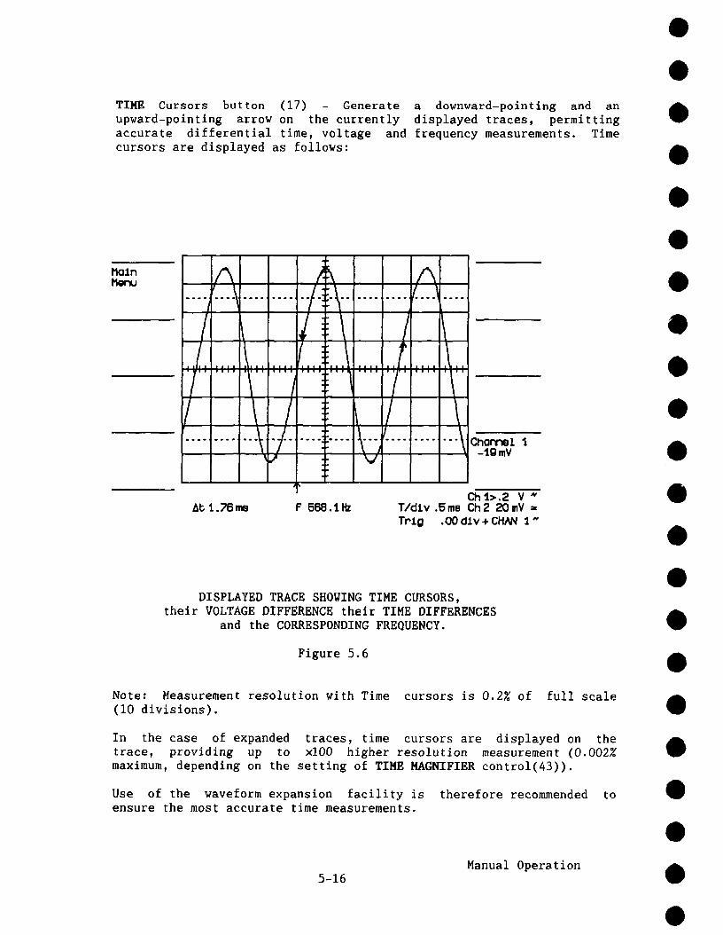
TIME Cursors button (17) - Generate a downward-polnting and upward-pointing arrow on the currently displayed traces, permittingaccurate differential time, voltage and frequency measurements. Timecursors are displayed as follows:
MalnM~u A
#.... j---l- -~
/,7 .....t ........7 .......I .....7/ t /.... 1 ...... -’~-/-i
/,.k-i-i::-\- ~ ......,! t /! ....../ ........t, .....
E1 .....f/" tI,,,
lt- ........p
At 1.78,m F 588.1Hz
Ii i
iii iii i
t....... t ChannQ1 1Jig mV
Ch I.>.2 V ~T/div .5ms Ch2 20mY =Trig .00 dlv + CHN~ ~.~
DISPLAYED TRACE SHOWING TIME CURSORS,their VOLTAGE DIFFERENCE their TIME DIFFERENCES
and the CORRESPONDING FREQUENCY.
Figure 5.6
Note: Measurement resolution with Time cursors is 0.2Z of full scale(I0 divisions).
In the case of expanded traces, time cursors are displayed on thetrace, providing up to ×100 higher resolution measurement (0.002Emaximum, depending on the setting of TIME MAGNIFIER control(43)).
Use of the waveform expansion facility is therefore recommended toensure the most accurate time measurements.
Manual Operation5-16

VOLTAGE Cursors button (16) - Generates two linear cursor bars whichprovide accurate differential voltage measurements when adjustedvertically on the currently displayed waveform. The REFERENCE andDIFFERENCE controls (38) serve to position the Reference and theDifference cursor bars.
Voltage cursor bars are displayed as follows:
R
A .....A ........
.... ~ .......V-
A A A
-I~ -I-I ......-I~ ......II I~ I.... , ....I...~... I... ~.......1’ .... / ....... \
~ll \J .... i::--V- --V~ ......V¯ .I. I-
Q14.>.2 V "T/oiLy .2me Ch2 2C)mV Tr’J.o .CX) dlv÷ CHNq 1
DISPLAYED TRACE SHOWING REFERENCE and DIFFERENCE VOLTAGECURSORS, and ALPHANUMERIC READOUT of TRACE AMPLITUDE
Figure 5.7
Note that measurement resolution with the VOLTAGE cursors is 0.2% offull scale (8 divisions).
CURSOR POSITIONING knobs (38) - In the case of Time and Voltagecursors, the REFEP~NCE control adjusts the Time and Voltage Referencecursor to the point used as measurement reference. The DIFFERENCEcontrol is then adjusted to move the Difference cursor to the desiredposition along the trace.
The + Marker cursor is moved along the displayed waveform by means ofthe REFERENCE cursor positioning knob alone.
Pressing the TRACKING button causes the Difference cursor to track theReference cursor at a fixed interval as determined by the DIFFERENCEcontrol (in the case of Voltage and Time cursors).
5-17Manual Operation

5.2 Menu Controls
After the Main Menu key (2) has been pressed, any one of the 9400A’sinteractive menus may be selected by pressing buttons (2)-(10). Figure5.8 shows the available menus as they appear on the 9400A. To obtain agiven menu, press the button adjacent to the menu desired.
Isls ¯,,,. ,,,,|,,,, ,,,,|,,,,,,,,,.,,,,|,,,,l,,,,a,,,,,
T/dlv. 2 nil Ch 2TrJ.g .20 cllv - CHN~ t :
9400A Main Menu and RELATED MENU KEYS
Figure 5.8
5.2.1 Store Menu
Using the STORE button (I), it is possiblethe waveforms currently in the 9400A’sreference Memories C and/or D.
to store either or both ofacquisition memories into
To store the currently acquired waveform, first stop the acquisition bypressing the SINGLE (HOLD) button (29). Once acquisition has stopped,press button (I) and respond to the messages displayed to the left the screen. The options are shown in Figure 5.9.
Manual Operation5-18

St, oreTrooe
1 ->HImC
Ch~2 ->
FunoE->HmC
Funo F ->
Chon 1. ->HImD
Chart2 ->
FunoE ->I’kmD
Funo F ->
Ret, ul-n/Conoel
Chl 50mY IT/dtv .2me Ch250mVTPLQ -- +LINE .
STORE TRACE MENU
Figure 5.9
Pressing buttons (2), (3), (6) or (7) causes an identical copy displayed waveform (or waveforms) to be stored into reference MemoriesC and/or D.
If acquisition is taking place when the store button (I) is pressed,the user is prompted with the message:
STOP ACQUISITION IN ORDER TO STORE
Manual Operation5-19

5.2.2 Panel Status Menu
The Panel Status menu provides a complete report of front panel controlsettings and permits on-screen adjustment of acquisition parameters.
PLOTTING
PANEL STATUS MENU
Figure 5.10
Vertical parameters:
Fixed V/dtv
The current setting of the front panel Vertical Sensitivitycontrol (27) with the VAR vernier in the fully clockwise positionis indicated.
Total V/div
The current setting of the front panel Vertical Sensitivitycontrol (27) plus the additional sensitivity range (up to x 2.5 the Fixed V/div setting) is provided by turning the VAR vernier(28) counterclockwise.
Manual Operation5-20

Trigger parameters:
Delay
In Figure 5.10 the indicated trigger delay is 10% Pre, meaningthat when in Main Menu the Delay arrow is positioned one divisionto the left of the center of the grid. In the case of apost-trigger delay setting9 this would be indicated in decimalfractions of a second (i.e. + 4.00 msec).
Level
The trigger level indicated in Figure 5.10 is displayed in termsof grid divisions. The 9400A displays the current trigger levelsetting in divisions when in the internal trigger mode. Itdisplays the setting in Volts when in the external trigger mode.
Time/point
Indicates the time between digitized points for the correspondingtime base setting.
Points/div
This parameter indicates the number of digitizeddivision on any non-expanded waveforms displayed.
points per
# Segments for SEQNCE
This parameter indicates the number of segments selected forsequential acquisition. On-screen modification of this parameteris possible by pressing the Modify # Segments button (4) to changethe indicated segment number from 8 to 250 in a rolling sequence.
Set CHAN 1 Attenuator (6) and set CHAN 2 Attenuator (7)
allow the user to enter probe attenuation factors of I0, i00 andI000.
Press the Return key (10) to list the available menus.
For information concerning the other parameters displayed on the PanelStatus menu, see Section 5.1.
5-21Manual Operation

5.2.3 Memory Status
The Panel Status menu displays acquisition parameters for waveforms tobe acquired after receiving a trigger signal. On the other hand, theMemory Status menu displays all acquisition parameters for waveformscurrently stored in the various memories of the 9400A.
The annotation used for Memory Status is similar to that of the PanelStatus menu. Pressing the Memory Status button (3) displays the MemoryStatus menu in Figure 5.11.
Ch t+2STATUS
llk~ GI.DSTATUS
Fun £~1r
PLOTTII~
ItDtORY STATUS v 2,0OFT
To¢.ol V/dlv EJO.O mV 150.0 mYOPP~#. .0 mV .0 mVCoupltr~-LLml~, ~ t HO, 0:1= AC 1 HI}, OFFTime (F’meq)/dlv .5 me .5 meTO:’|lpr~ + ~d.tv ~00 rm, ~ 200 I’m, 2500TrLg-Deloy 9.8X Pre 9.8X Pr~Tr-I.m~l + Slq:~ .OOcRv, + .OOcRv, +Tr~_~i-__.-~e ÷ Ca:x~ 04AN 1, DC CHAN ~, []CI1mory LIIt~ -~)00,2E(X)O -;~X), 2EO00Rm}or’d-Type SINi~ 5INIEE
MEMORY STATUS CHAN 1 and CHAN 2Figure 5.11
Pressing button (2), (3) or (4) while in the memory status menu display the acquisition parameters of waveforms stored in acquisition,expansion and storage memories respectively.
5-22Manual Operation

Ch t+2STATUS
F~p~m
l~m GtoSTATUS
Fun E+F
Plmory C
50O IV4000 mV13(3600, OFF.2mo80rm, 2500
.4Z I:Me
LINE , 13C0,26000
SINGLEA~Cl) t252, 20
5
V 2.08FT~mory o50.0 mV.OmVDOEO O, OFF.Eme200 no, 2500
.OX Pre-20.0 V , -EXT/IO, DC-~000,260(X)5INGLE
Ch t+2STATUS
~xp A+8
I~mC+DSTATUS
FunE+F
PLOTTING
TRACE A,
ItEI’IORY STATUS
B EXPAND STATUS MENU
Figure 5.12
Mmmry C
5OO iiV4000 mVDCEO O, OFF.2mo80rm, L:~O0
.4Z I:Me
LXHE , 13C0,26000
5[NGI.[A~(l) t252,20
1
MEMORY STATUS C and D
Figure 5.13
V 2.08FTHm.ory D
50.OmV.OmVDCEO 0, OFF.6me2CX3 rm, 2500
.OX Pre-20.OV , -E~T/tO, OC-7(XX),260005INGLE
5-23Manual Operation

The indication in the upper right-hand corner of Figures 5.12, 5.13,5.14 corresponds to the software version implemented in the scope.
5.2.4 Storage and Recall of Front Panel Setups
Pressing the Store PANEL or Recall PANEL buttons ((4) and (5),respectively) enables storage or recall of up to seven different frontpanel acquisition parameter settings.
,,,, ........ :::.::::.::::,
SP~m’eParml
-> Pa’ml 5STORE
-> I%:’ml 2
-> I::-ml 9STORE
-> I:(a’ml 4 ..........................
-> I:m-ml 5STORE
-> Pa-ml 8
-> I:onel 7STCI~
Return
STORE and RECALL FRONT PANEL SETUP MENUS
Figure 5.14
Once you have obtained a satisfactory front panel setup, simply callthe Store PANEL menu by pressing button (4); then press any one of thebuttons (2) through (8) to store this front panel setup where required.Press the Return button (10) to go back to the Main Menu and continuenormal scope operation.
Manual Operation5-24
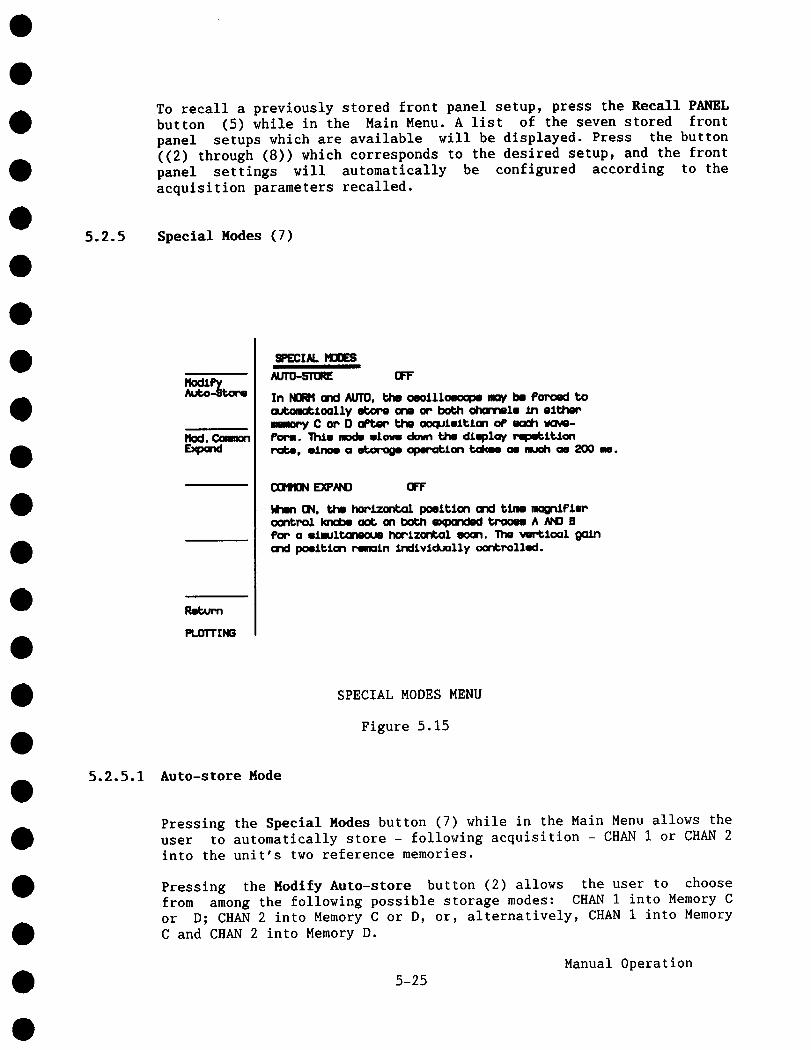
To recall a previously stored front panel setup, press the Recall PANELbutton (5) while in the Main Menu. A list of the seven stored frontpanel setups which are available will be displayed. Press the button((2) through (8)) which corresponds to the desired setup, and the panel settings will automatically be configured according to theacquisition parameters recalled.
5.2.5 Special Nodes (7)
Mod. Common
Return
PLOTTING
¯ :q~IAL MODESAUTO-STORE OFF
In ~ and AUTO, the oeollloeoope moy be Por-o~ too,k~mc~loolly etxx,e one or both ~tm’lnell In olt,~’memmory C or O oPtm, p.j.m ooqutmltton o4’ ~¢h tKMB-POP,,. lhJ.m modw wLo~ down tim dJ.mplay rq:m~lt;lonr’~be, ell’me a ~ opm-c~ion t.d¢~ oe much as 200 me.
COPItON E~N~D OFF
ktwn ON, the hoplzont~l poeitlan and time .mgnlFleroor~roi knd:e ao~ on both expandmd tPoo~ A AND BPoP o olmult~neoue horizontal ooan. The vertloalarxJ paml~lon remain Indivldua11y aor~rolled.
SPECIAL MODES MENU
Figure 5.15
5.2.5.1 Auto-store Mode
Pressing the Special Modes button (7) while in the Main Menu allows theuser to automatically store - following acquisition - CHAN I or CHAN 2into the unit’s two reference memories.
Pressing the Modify Auto-store button (2) allows the user to choosefrom among the following possible storage modes: CHAN I into Memory Cor D; CHAN 2 into Memory C or D, or, alternatively, CHAN I into MemoryC and CHAN 2 into Memory D.
5-25Manual Operation
This is a useful feature for very low repetition rate signals acquiredin the NORMAL trigger mode. Subsequent display of the selectedreference memory provides the user with a lasting waveform displaywhich can be studied long after the originally acquired signal has beenerased. In the NORMAL trigger mode the CHAN 1 and CHAN 2 displays areautomatically erased after a two second interval to warn the user thata proper trigger is not available.
5.2.5.2 Common Expand Mode
Section 5.1.4 discusses independent expansion of single traces todisplay a magnified portion of the waveform from CHAN 1 and/or CHAN 2,Memories C and/or D, or of Function E and/or F if the 9400A is equippedwith WPOI Waveform Processing firmware. However, in certainapplications, it is convenient to be able to move the intensifiedregion along two different traces simultaneously. This is the purposeof the Common Expand mode.
In this mode it is possible to either synchronize the intensifiedregions of the two source signals, or to maintain a fixed time intervalbetween them, in which case the intensified regions for each trace willmove horizontally at a fixed interval. (See Section 8.11 for an exampleof intensified regions shifting on two traces expanded in the CommonExpand mode).
In the Common Expand mode, when the user is examining two expansions ata fixed interval (he may re-synchronize them by pressing the RESETbutton (41)) both expansions are shifted to the center of the grid.Turning the Horizontal POSITION control (39) until both of theintensified regions move off the screen will also re-synchronize them.
In the Common Expand mode, only the Horizontal POSITION control (39)and TIME MAGNIFIER control (43) act simultaneously on the intensifiedregions on both the EXPAND A and B signal source, while the VERT GAINcontrol (42) and Vertical POSITION control (40) act independently each expanded waveform.
Note that when the Common Expand mode is called, the EXPAND Amagnification factor applies to both A and B expansion.
5.2.6 RS-232-C Setup (8)
Two RS-232-C ports are available on the rear panel of the 9400Apermitting remote oscilloscope operation and data transfer, as well asconvenient plotter interfacing.
5-26Manual Operation

When in the main menu, pressing RS-232-C SETUP button (8) calls interactive menu enabling configuration of both of the 9400A’s RS-232-Cports for a particular application. Parameters for theplotter-dedicated RS-232-C port (57) are displayed in the lower portionof the screen, while those for the remote RS-232-C port (56) arepresented in the upper portion of the screen.
I~wioueVALUE
Nex~
RS~32 - RemOte c~nbrol port
Saud r’~e: !~
C~ro~er Length Cblt6):
Parity: norm
Number oF stop bits: I
RS232 - Plotter port
Baud rate: 9600
Charooter Length Cblt~):
Parity: none
Number oP etop bite: I
RS-232-C SETUP MENU
Figure 5.16
To modify any of the parameters displayed, first select the field to bemodified. The rectangular frame around parameter values indicates thecurrently selected field. Pressing the Previous FIELD button (2) willcause the frame to move towards the top of the list, whereas pressingthe Next FIELD button (3) will move the frame downwards.
Following field selection, the current value of the field may bemodified by pressing either the Previous (6) or Next VALUE (7). Baud rate is selected from a set of values in the range ii0 through19,200 baud. The possible settings of character length are 6, 7, and 8;parity, none, even or odd; and number of stop bits, I and 2.
5-27Manual Operation
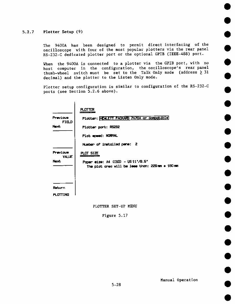
5.2.7 Plotter Setup (9)
The 9400A has been designed to permit direct interfacing of theoscilloscope with four of the most popular plotters via the rear panelRS-232-C dedicated plotter port or the optional GPIB (IEEE-488) port.
When the 9400A is connected to a plotter via the GPIB port, with nohost computer in the configuration, the oscilloscope’s rear panelthumb-wheel switch must be set to the Talk Only mode (address > 31decimal) and the plotter to the Listen Only mode.
Plotter setup configuration is similar to configuration of the RS-232-Cports (see Section 5.2.6 above).
PPovlouoVALUE
Next;
Reb~Pn
PLOTTING
PLOTTER
Plobt~w’: IHE~-ETT PACKARD 7+70A om oompob~hlol
Plobbem pore: RS292
Plob speed: NORHN.
NuMbem oF Installed pane: Z
PLOT SIZE
Popem eLze: A4 (ISO) - USIt°/8.5"The plot; amea w111 be 1~ bhon: 22gram ¯ 1BO~
PLOTTER SET-UP MENU
Figure 5.17
5-28Manual Operation

The user can choose the following parameters:
Plotter Type:
Plotter Port:
Plot Speed:
HP7470A (or compatible), Philips PM8151(or compatible),Tektronix or Graphtec FP 5301
RS-232-C or GPIB (IEEE-488)
Normal or Low Speed
Number ofInstalled Pens: I to9
Plot Size: ISO A5 (US 8.5" x 5.5"), ISO A4 (US ii" 8.5"),IS0 A3 (US 17" x ii") or non-standard
Non-standard: In the case of non-standard paper sizes, the size ofthe grid square can be chosen between 0 to 99.9 mm in0.I mm steps; lower left corner position from 0 to999 mm (for both X and Y coordinates) in I mm steps.
* If GPIB is selected by no GPIB board is installed (basic 9400A), theinstrument may lock up when the screen dump button is pressed.
Manual Operation5-29


SECTION 6
6.1
REAR PANEL CONTROLS AND CONNECTORS
Fuse Protection
6.2
The power supply of the 9400A is protected against short circuits andoverload by means of a T(slow) 1.6/ 250 V fuse for units which canoperate on 220 V or 115 V mains voltage (switch selected) or a T (slow)3.15/ 250 V fuse for units operating only on 115 V mains voltage. Thefuse is located under the 115 to 220 V mains voltage selector drumcover.
Accessory Power Connectors (51)
Two LEMO RA 0304 NYL connectors have been provided to permit use of FETtype probes with the 9400A. These connectors provide output voltages of+ 5 V, ± 15 V and GND connection, suitable for most FET probes.
The maximum output current per connector must be limited to 150 mA foreach of the three voltages.
6.3 Battery Pack (52)
The battery pack consists of two KR 15/51, 1.2 V rechargeable NiCdbatteries enabling retention of front-panel setups for 6 months in caseof power failure or whenever the 9400A is switched off. The batterypack is automatically recharged during operation.
The battery pack can be accessed by pressing the plastic latch at thetop of the cover and pulling it downward and toward the user.
6.4 GPIB and RS-232-C Port Selection (54)
The 9400A’s rear panel thumbwheel switch is used to set addresses forprogrammed or remote oscilloscope operation. Any one of addresses 31-99selects the RS-232-C port. Addresses 0-30 define the 9400A’s addresswhen using the optional GPIB (IEEE-488) port.
GPIB and RS-232-C pin assignments are clearly indicated on the rearpanel next to each connector.
6-1Rear Panel Controls and Connectors

6.5 Plotter Connector (57)
In addition to the RS-232-C port (56) used for remote 9400A operation,a second RS-232-C port (57) has been incorporated to facilitate directinterfacing of the 9400A with a digital plotter. Plotters are used forhard copy archiving of displayed waveforms and other screen data. Pinassignments for the plotter connector are identical to those of theremote RS-232-C port (56).
While a plotter unit connected to the 9400A’s RS-232-C port can becomputer controlled from a host computer via the optional GPIB port,the oscilloscope’s on-board digital plotter drivers permit hard copiesto be made without an external computer.
Plotter connector pin assignments:
Pin # Description
2 T x D3 RxD4 RTS5 CTS
20 DTR
6 DSR1 GND7 SIG GND
Transmitted Data (from the 9400A)Received Data (to the 9400A)Request To Send (always on) (from the 9400A)Clear To Send (to the 9400A)When TRUE, the 9400A can transmit.When FALSE, transmission stops.Used for 9400A output hardware handshake.Data Terminal Ready (from the 9400A)Always TRUE.Data Set Ready (to the 9400A)Protective GroundSignal Ground
This corresponds to a DTE (Data Terminal Equipment) configuration.
6-2Rear Panel Controls and Connectors

SECTION 7
REMOTE OPERATIONS
7.1 Progr.mmed Control
Most of the front panel and internal functions of the 9400A can beremotely controlled using a set of high-level, English-like commandsand mnemonics. For example, a command followed by <?> tells the scopeto transfer to the host computer the value of the control settingdefined by the command. It is thus possible to read the complete statusof the instrument by repeated queries. It is also possible to save theentire status of the instrument in binary format with a single command.The 9400A’s remote control facility allows complex measurementprocedures and instrument setups, a particularly useful feature inexperimental and automated testing environments.
The 9400A can be programmed via the rear panel RS-232-C port interfacedwith a computer terminal or a computer. Remote control is also possiblevia GPIB (IEEE-488 bus) if the 9400A has been fitted with the optionOP02. In this case data transfer rates are relatively faster.
To help users who wish to remotely control the Models 9400 (125 MHzbandwidth) and 9400A (175 MHz bandwidth) oscilloscopes, LeCroy havepublished the following application notes which are available onrequest:
ITI 002: Linking the LeCroy 9400 to an IBMR PC-AT via the RS-232-CAsynchronous Interface.
ITI 005: Linking the LeCroy 9400 to an IBM PC-AT via GPIB.ITI 006: Linking the LeCroy 9400 to an HP 9000 Model 216 controller.
7.2 RS-232-C Ports (56 and 57)
The 9400A has two RS-232-C ports. One is available for computer orterminal controlled oscilloscope operation, the other for plotterinterfacing. The RS-232-C ports provide an asynchronous data transferrate of up to 19,200 baud.
7-1Remote Operations

RS-232-C Pin Assignments
The remote RS-232-C pin Assignments (indicated on the rear panel) areas follows:
Pin # Description
2 TxD3 RxD4 RTS5 CTS
2O DTR
6 DSR1 GND7 SIG GND
Transmitted Data (from the 9400A)Received Data (to the 9400A)Request To Send (always on) (from the 9400A)Clear To Send (to the 9400A)When TRUE, the 9400A can transmit.When FALSE, transmission stops.It is used for the 9400A output hardware handshake.Data terminal ready (from 9400A). If the softwareXon/Xoff handshake is selected it is always TRUE.Otherwise (hardware handshake) it is TRUE when the9400A is able to receive characters and FALSE when the9400A is unable to receive characters.Data Set Ready (to the 9400A)Protective GroundSignal Ground
This corresponds to a DTE (Data Terminal Equipment) configuration.
Although descriptions vary slightly, pin assignments for the dedicatedplotter interface (Section 6.6) are identical to those for the remoteRS-232-C connector above.
7.3 GPIB Port (Option OP02 only) (55)
The 9400A’s GPIB interface (optional) complies with IEEE-488 (1978)standards, and is intended to provide high-speed data transfer ineither the ASCII or binary format between the 9400A and the computer towhich it is interfaced. The maximum data transfer rate, depending onthe controller used, may be as high as 400 kilobytes/sec.
GPIB Port Selection (54)
As mentioned in Section 6.5, the 9400A’s rear panel thumbwheel switchis used to set addresses for programmed or remote oscilloscopeoperation. Addresses 0-30 define the 9400A’s address when using theGPIB (IEEE-488) port; using any one of addresses 31-99 selects theRS-232-C port. The thumbwheel is read at power ON only. Whenever theGPIB address is changed, the power must be turned off and on again.
GPIB functions are clearly indicated on the rear panel next to the GPIBconnector.
7-2Remote Operations

GPIB Functions
The following is a list of the various functions9400A’s rear panel GPIB connector:
AHISHI
L4T5SRIRL2DCIDTIPP1
COE2
Complete Acceptor HandshakeComplete Source HandshakePartial Listener FunctionComplete Talker FunctionComplete Service Request FunctionPartial Remote/Local FunctionComplete Device Clear FunctionComplete Device TriggerParallel Polling: remote configurationNo Controller FunctionsTri-state Drivers
provided via the
7.4 GPIB and RS-232-C Command Format
7.4.1 Introduction
All the remote control commands apply equally to communication via theGPIB and RS-232-C ports. (Note that GPIB commands should not be usedwhen Option 0P02 is not fitted in the 9400A.) Certain functions,however, which are part of the GPIB standard (such as Device Clear orGroup Execute Trigger) must be implemented as separate commands for theRS-232-C interface (see Section 7.6.10). The command syntax compatible with IEEE Recommended Practice for Code and FormatConventions (IEEE Standard 728-1982).
In GPIB, the predefined control commands, such as Device Clear, GroupExecute Trigger, Set Remote or Set Local, are part of the device drivercommands. Therefore the 9400A only has English-like commands for thesefunctions in RS-232-C inferfacing applications. The user must consultthe manual for his GPIB-interface driver in order to determine the formof these special commands.
Commands are formed of easy-to-read, unambiguous English words, withabbreviations (typically 2 to 4 characters) being used to achievehigher throughput. Short and long formats may be freely substituted forone another.
The execution of certain commands depends on whether the 9400A is inthe REMOTE or LOCAL state.
7-3
Remote Operations

When the 9400A is in LOCAL:
- All the front panel controls are active.- Reading the 9400A by remote control is possible.- The status byte masks (see MASK command) and the communications
protocol (see COMM command) may be written, status bytes may cleared.
When the 9400A is in REMOTE:
- All the front-panel controls are deactivated, except the twodisplay intensity controls and the left-hand side menu buttons.
- All the remote commands are executed.- A special command (SCREEN) exists to deactivate the front panel
display intensity controls and allows them to be set remotely.
7.4.2 Compound Commands
One or several commands can be sent to the 9400A in a message endingwith <END>. In GPIB transfers, <END> is the line which marks the EOI(End of Information). In this case, <END> is <;>,<CR> or <LF>. RS-232-C transfers, <END> is a user-selectable string; the default is<CR>.
Where multiple commands are used to compose a message, each command isseparated from the following one with a <;>, a <CR> or a <LF> or withany combination of these characters.
Example:
TRIG SLOPE POS; TIME/DIV 50 NS <END>
represents 2 commands where <;> is used to separate them.
Commands are executed only after <END> is received. Exceptions to thisrule are mentioned later (see Section 7.4.6).
7.4.3 Command Format
Simple commands consist of a header, indicating the desired operation.The header is usually followed by one or more parameters used todescribe the desired operation in greater detail.
HEADER (<SPACE>, <,> or <=>) Parameter i, Parameter 2, etc.
7-4Remote Operations
The header may be separated from Parameter 1 by either a space, comma,equals sign or any combination of these. Parameters MUST be separatedfrom one another using a comma.
Headers and key-word parameters may be transmitted using either thefull or an abridged format. Both upper and lower case characters arevalid and may be used interchangeably.
Numbers must be in accordance with ANSI X3.42-1975 standards and may betransmitted as integers, or in scientific notation, with or withoutexponents. Waveform data values, however, can only be transferred asintegers (8- or 16-bits). Suffixes are optional (but acceptable onlywhen specifically mentioned).
Example:
The following commands are all legal ways of setting the verticalgain of CHANNEL i to I00 mV/div:
CHANNEL 1VOLT/DIV .ICHANNEL 1VOLT/DIV,IO0 MVOLTCIVD=IOOE-03 VOLTCIVD I00 MV
The expression <i00 MV> is considered as a single parameter with asuffix; therefore no comma is allowed to separate them. The spaceseparating the parameter value and the suffix is optional.
7.4.4 Answers from the 9400A
As well as specifying a new parameter setting, it is also possible toquery the 9400A in order to obtain a current value. Such queries arealways indicated by a question mark.
Example:
TIME/DIV ?
instructs the 9400A to transmit a characterits current time base value.
string representing
Answers from the 9400A are sent in a message followed by(see COMM TRAILER command) and <END>.
the TRAILER
Remote Operations7-5
Example:
When set to I00 nsec/div, the answer to the query would be:
TD 100E-09<CR><LF><END>,
where <CR><LF> is the default TRAILER, and<END> = another <CR>, when using RS-232-C (unless modified with
the command RS CONF).= EOI-line ACCOMPANYING <LF>, when using GPIB.
If the 9400A generates multiple responses to a single messagecontaining queries, it will send a separate response for each query.
7.4.5 Flushing of the 94OOA’s Output Buffer
When the 9400A generates an answer to a query or outputs a data streamin response to a transfer command, the host computer should read thedata. If it fails to do so, the 9400A may become blocked when trying tooutput data (this does not occur with a response of less than 80characters, since the output is buffered).
~henever the 9400A receives a new command message, upon detection ofthe <END> of this message, it flushes the output buffer of allresponses due to the previous command message. If the 9400A detects anew <END> from a new command message while still treating a previouscommand message, it aborts those (previous) commands which generateoutput data, but not the new commands. The 9400A assumes that the useris not interested in the answers to previous commands since he issending another command message rather than reading the responses.
7.4.6 Command Synchronization with Data Acquisition
Some remote commands cannot be executed at all times, e.g. it is notpossible to read channel 1 or channel 2 while the oscilloscope is armedand waiting for a trigger, since the memories of the two channels arecontinuously being written into.
The user can avoid such situations entirely by only executingsingle-shot acquisitions (TRIG MODE SINGLE) and by checking that bit of status byte 4 (TRIGGERED bit) is set to one (indicating that acquisition is complete) before sending the READ command.
Another way is to send the command to read channel 1 or channel 2. The9400A automatically defers the execution of this command until awaveform has been acquired. It is thus possible to also read waveformswhile the instrument is in the trigger modes NORM or AUTO, i.e.practically "on-the-fly".
7-6Remote Operations
Execution of the command is also deferred when using some other remotecontrol commands, in particular the command STORE channel I orchannel 2, and the special command WAlT whose sole purpose is to forcesuch a synchronization. (See Section 7.6.6 "Other Remote Commands".)
7.4.7 Character Strings
Stringsplottercommand). The string mustdefault string delimiterCOMM STRDELIM command).
may be displayed (see MESSAGE and KEY commands), sent to (see the TRANSMIT command) or used as Prompt (see COMM PROMPT
be delimited by string delimiters. Theis <"> and may be changed (see the
Example:
COMM STRDELIM 47; MSG /OKAY/
Defines </> (decimal ASCII 47)display OKAY on the screen.
The TRANSMIT command also outputsdecimal ASCII using a \nnn format.
Example:
TRANSMIT "\B27AB"
as the string delimiter and will
characters that are specified in
Can be used to transmit to the plotter the character ESC (decimalASCII 27) followed by <A> and <B>.
Ifcharacters, then <\\> is to be used.
Example:
TRANSMIT "AI\\A2"
Instructs the 9400A to transmit the string AI\A2 to the plotter.
Note:"\nnn" or "\\" represent only one character of the ASCII string count.
the backslash character <\> is to be transmitted along with other
7.4.8 Prompt
The 9400A may generate a PROMPT (see COMM-PROMPT command) when decodes the <END> message in a command message. This PROMPT will be putinto a message as is done with all other 9400A responses (see Section7.6.7 7)).
Remote Operations7-7

7.4.9 Errors and Adapted Values
When it treats a command, the 9400A checks its validity. The list oferrors is presented in Section 7.6.8 (ERROR status byte).
In general:
- A SYNTAX ERROR is produced when the structure of a command iswrong, or if a command, a key-word parameter or a suffix is notrecognized.
- A SEMANTIC ERROR is produced when thewrong combination of parameters or ifnot valid.
command is composed of aa numerical parameter is
- An ENVIRONMENT ERROR is produced when the command, although itis valid, cannot be accepted, the 9400A not being in the stateto do so.
When an error is detected, the corresponding code is loaded into statusbyte 6, and the bit # 5 of status byte 1 is set.
Some commands cause bit 0 of status byte i (VALUE ADAPTED bit) to set when the 9400A detects a numerical value or a parameter out ofrange. The value is always modified to the closest legal value.
7.5 Data Block Transfers
Data (9400A setup values, waveform values, waveform descriptor) aretransferred between the 9400A and the Host Computer (see the READ orSETUP commands, Section 7.6.5) or between the Host and the 9400A (seeWRITE or SETUP commands) in one or several blocks. Data blocks arenever contained within a read or write command, but are alwaysseparate. This section explains only the overall block structure. Forthe interpretation of the data, see Section 7.10.
Examples:
Reading a waveform from channel i of the 9400A:
- Host sends the command READ,CHANNEL 1.DATA<END> to 9400A.
- 9400A responds with one (or several) dataformats described below, and terminates<END>.
blocks in one of thewith <TRAILER> and
7-8Remote Operations

Thus, the overall command sequence and data structure is the sameas for queries.
Sending a new setup block to the 9400A:
- Host sends the command SETUP<END> to 9400A.
- Host sends thecomposed of a<END>.
data blocks to the 9400A. Each data block ispreamble, the data, an optional postscript and
Here, the setup data cannot be directly appended to the setupcommand, but must be separated by <END>.
Several block formats are available for read and write; they aredistinguished from each other by the preamble. The command COMM FORMATselects the format.
Format A: GPIB only, binary format, no checksum.
Preamble:
Data:
#Abb where bb is the number of data values that will besent (2 binary bytes).
One binary byte for each 8-bit value, two binary bytesfor each 16-bit value.
Postscript: None.
Format L: GPIB or RS-232-C, ASCII format.
Preamble: #L<count>, where <count> isthat will be sent.
Data: <data>, where <data> are data values in ASCII.
Postscript: None.
the number of data values
<count> and <data> are in the same format but do not necessarily havethe same number of characters. However, <count> is always treated as aWORD (16 bits), whereas <data> may be chosen as a BYTE (8 bits) or WORD. The choice of formats (see COMM FORMAT command) is the following:
HEX:
UNSIGNED FIXED:
UNSIGNED SHORT:
BYTE (8 bits value) WORD
xx (2 hex digits) xxxx
nnn (3 decimal digits) nnnnn
(16 bits value)
(4 hex digits)
(5 decimal digits)
,n (I to 3 decimal digits) ,nnnnn (I to 5 decimaldigits)
7-9Remote Operations
The HEX and UNSIGNED FIXED are fixed size formats, whereasUNSIGNED SHORT is a variable size format. Therefore, it requires commasto separate the values.
Examples:
HEX format: #LOOOA0102030405060708090AUNSIGNED FIXED: #L...I0..I..2..3..4..5..6..7..8..9.10
UNSIGNED SHORT: #L,10,1,2,3,4,5,6,7,8,9,10
Each dot repre-sents a spacecharacter
Note:The conversion type and the size must be fixed before reading ANDwriting data.Data transfers via RS-232-C can only be made in ASCII formats.
If the host computer allows only small amounts of data to be sent orread, the transfer may be partitioned into several blocks of theselected format. The maximum length of each block is determined by theCOMM BLOCKSIZE command. The length includes all bytes or characters ofthe -block as well as characters which may compose the <TRAILER> and<END>.
The transfer will be structured as follows:
I st Block -- <TRAILER><END> -- 2nd Block -- <TRAILER><END> -- ........ -- Last Block -- <TRAILER><END> -- END block -- <TRAILER><END>
Where the END block is:
#I
When reading data from the 9400A, the exact form ofdetermined by the command COMM TRAILER. <END> is:
the TRAILER is
<END> = <CR> when using RS-232-C (unless modified with the commandRSCONF).
= EOI ACCOMPANYING the last character of TRAILER, when in GPIB.
If the 9400A receives another command message, terminated with <END>,while sending data, the transfer is aborted and status byte 6 (ERROR)is set to the value i.
Data may be lost if the readout sequence is interrupted with a SerialPoll or by the untalk command.
7-10Remote Operations

Thus, the overall command sequence and data structure is the sameas for queries.
- Host sends thecomposed of a<END>.
Sending a new setup block to the 9400A:
- Host sends the command SETUP<END> to 9400A.
data blocks to the 9400A. Each data block ispreamble, the data, an optional postscript and
Here, the setup data cannot be directly appended to the setupcommand, but must be separated by <END>.
Several block formats are available for read and write; they aredistinguished from each other by the preamble. The command COMM FORMATselects the format.
Format A: GPIB only, binary format, no checksum.
Preamble: #Abb where bb is the number of data values that will besent (2 binary bytes).
Data: One binary byte for each 8-bit value, two binary bytesfor each 16-bit value.
Postscript: None.
Format L: GPIB or RS-232-C, ASCII format.
Preamble: #L<count>, where <count> is the number of data valuesthat will be sent.
Data: <data>, where <data> are data values in ASCII.
Postscript: None.
<count> and <data> are in the same format but do not necessarily havethe same number of characters. However, <count> is always treated as aWORD (16 bits), whereas <data> may be chosen as a BYTE (8 bits) or WORD. The choice of formats (see COMM FORMAT command) is the following:
HEX:
UNSIGNED FIXED:
UNSIGNED SHORT:
BYTE (8 bits value) WORD
xx (2 hex digits) xxxx
nnn (3 decimal digits) nnnnn
(16 bits value)
(4 hex digits)
(5 decimal digits)
,n (I to 3 decimal digits) ,nnnnn (I to 5 decimaldigits)
7-9Remote Operations

The HEX and UNSIGNED FIXED are fixed size formats, whereasUNSIGNED SHORT is a variable size format. Therefore, it requires commasto separate the values.
Examples:
HEX format: #L000A0102030405060708090AUNSIGNED FIXED: #L...I0..I..2..3..4..5..6..7..8..9.10
UNSIGNED SHORT: #L,I0,I,293,4,5,6,7,8,9,10
Each dot repre-sents a spacecharacter
Note:The conversion type and the size must be fixed before readingwriting data.Data transfers via RS-232-C can only be made in ASCII formats.
AND
If the host computer allows only small amounts of data to be sent orread, the transfer may be partitioned into several blocks of theselected format. The maximum length of each block is determined by theCOMM BLOCKSIZE command. The length includes all bytes or characters ofthe -block as well as characters which may compose the <TRAILER> and<END>.
The transfer will be structured as follows:
ist Block -- <TRAILER><END> -- 2nd Block -- <TRAILER><END> -- ........ -- Last Block -- <TRAILER><END> -- END block -- <TRAILER><END>
Where the END block is:
#I
When reading data from the 9400A, the exact form ofdetermined by the command COMM TRAILER. <END> is:
the TRAILER is
<END> = <CR> when using RS-232-C (unless modified with the commandRS_CONF).
= EOI ACCOMPANYING the last character of TRAILER, when in GPIB.
If the 9400A receives another command message, terminated with <END>,while sending data, the transfer is aborted and status byte 6 (ERROR)is set to the value I.
Data may be lost if the readout sequence is interrupted with a SerialPoll or by the untalk command.
Remote Operations7-10

7.6 Commands
7.6.1 Notation
In this section the following notation is used to explain the commands.However, these symbols must not be sent to the 9400A as part of acommand.
[ to ]
< >
)
denotes the range of a numerical value.
denotes the choice of parameters.The options are listed vertically.
denotes the abridged format of a keyword.
denotes a separator which may be <,> or a space or <=>.The last two are only acceptable between the header andthe first parameter~ not between parameters.
indicates commands which can be executed in REMOTE only.Queries (terminated with a <?>) are always allowed.
** indicates commands which can only be executed in REMOTE whenthe display intensity controls have also been set to REMOTE.
Example:
TIME/DIV (TD) , < ? < [ 2 NS to I00 S ] >
"TIME/DIV" is the long format of thetime base.
"TD" is the short form equivalent ofbe used at all times.
command for controlling the
"TIME/DIV". Either form may
The comma is the separator between the header and the firstparameter. It may be replaced by a space or by an equal sign <=>,or by any combination of these. Note that subsequent parametersMUST be separated from each other by commas only.
The parentheses < > show that the choice of the first (and only)parameter is either <?> or a time base value in the range of2 nsec to I00 sec.
The asterisk <*> indicates that this command can only be executedwhen the 9400A is in the REMOTE state. However the query"TIME/DIV 7,,̄ , can be executed at any time.
7-11Remote Operations

7.6.2 Acquisition Parameter Commands
i) TIME/DIV (TD) , <? >< [ 2 NS to I00 S ] >
Other available suffixes are: US (Bsec, microseconds) and MS (msec,milliseconds).
The 9400A sets the VALUE ADAPTED bit:- if an out-of-range value is given.- if a value outside the incremental steps of i, 2, 5 is given.
Examples:
TD = ?
TD 20 USTIME/DIV 12 MS
Instructs the 9400A to send the current time basevalue.Sets the 9400A to 20 Bsec per division.Sets the 9400A to I0 msec; since the value ismodified from 12 msec to I0 msec, the VALUE ADAPTEDbit in status byte 1 is set.
2) INTERLEAVED (IL) , <? >< ON > *< OFF > *
Enables or disables Interleaved Sampling.
The 9400A sets the ENVIRONMENT ERROR:- if ON command is sent while the time base is greater than 2 US.- if OFF command is sent while the time base is less than 50 NS.
3) TRIG DELAY (TRD) , < ? < [ 0.00 % to i00.00 % ] >< [ -0.04 NS to -I000000 S ] >
Positive format:Negative format:
pre-trigger.post-trigger delay.
Valid delay v~ues correspond to 0 to i0000 time base divisions insteps of 1/50 of a division. If the TIME BASE is changed, thedelay remains the same or may change just slightly due to rounding,provided that it does not exceed I0000 divisions.
Note:In the case of post-trigger delay, the remote value is negativewhile the corresponding value displayed on the screen is positive.
7-12Remote Operations

The 9400A sets the VALUE ADAPTED bit:- if a positive out-of-range value is given.- if a negative value corresponding to more than i0000 divisions is
given.
4) TRIG LEVEL (TRL) , < ?
, < [ -5.00 DIV to 5.00 DIV ] >
when the oscilloscope is set to one of theinternal trigger sources (CHANNEL_I orCHANNEL_2).
, < [ -2.00 V to 2.00 V ] >
when the oscilloscope is set to in the EXTtrigger source.
, < [ -20.0 V to 20.0 V ] >
when the oscilloscope is set to the EXT/10trigger source.
When the oscilloscope is set to LINE trigger source, this commandhas no meaning and no error will be reported. In the case of POS_NEGtriggering, only a positive value is meaningful.
The 9400A sets the VALUE ADAPTED bit:- if an out-of-range value is given.
The 9400A sets the ENVIRONMENT ERROR:- if the DIV suffix is sent instead of V or if the V suffix is sent
instead of DIV.
5) TRIG COUPLING (TRC) , < ? >< AC > *< DC > *< LF REJ (LF) *< HF-REJ (HF) *
6) TRIG MODE (TRM) , < ? >< SEQNCE (SE) > *< AUTO (AU) > *< NORM (NO) > *< SINGLE (Sl) > *
The 9400A sets the ENVIRONMENT ERROR:- if SEQNCE is sent while the 9400A is in Interleaved Sampling.
7) TRIG SOURCE (TRS) , < ? < CHANNEL i (CI) *< CHANNEL-2 (C2) *< LINE (eI) > *< EXT (EX) > *< EXT/IO (E/IO) > *
Remote Operations7-13
8) TRIG SLOPE (TRP)
9) SEGMENTS (SEG)
, < ? >< POS (P0) > *< NEG (NE) > *< POS NEG (PN) *
, <? ><8 > *< 15 > *< 31 > *< 62 > *< 125 > *< 250 > *
Indicates or selects the number of segments for waveforms acquiredin SEONCE mode.
i0) CHANNEL 1 VOLT/DIV (CIVD)CHANNEL 2 VOLT/DIV (C2VD)
, <? >< [ 5.000 MV to 12.500 V ] >
The range of the Volts/div setting is limited to 2.5 Volts perdivision in the case of 50 Q coupling.
Note that this value corresponds to the 9400A input gain. It doesnot take probe attenuation factors into account.
The 9400A sets the VALUE ADAPTED bit:- if an out-of-range value is given.
Examples:
CHANNEL_2_VOLT/DIV,500 MVCIVD=.5C2VD 120 MV
Sets channel 2 to 500 mV/divSets channel 1 to 500 mV/divSets channel 2 to 120 mV/div bychoosing I00 mV/div fixed gain andsetting the variable gain to therequired value.
ii) CHANNEL 1 ATTENUATION (CIAT)CHANNEL 2 ATTENUATION (C2AT)
, <? >< i > *< I0 > *< i00 > *< I000 > *
Indicates or selects the attenuation factor of the probe.
12) CHANNEL 1 OFFSET (CIOF)CHANNEL 2 OFFSET (C20F)
, <? >< [ -8.00 DIV to 8.00 DIV ] >
The 9400A sets the VALUE ADAPTED bit:- if an out-of-range value is given.
7-14Remote Operations

13) CHANNEL I COUPLING (CICP)CHANNEL 2 COUPLING (C2CP)
, <? >< AC 1 MOHM (AIM) > *< DC 1 MOHM (DIM) > *< GND > *< DC 50 OHM (D50) > *
14) BANDWIDTH (BW) , <? >< ON > *< OFF > *
15) STOP
Stops the acquisition of a signal. This command may be used toreturn the 9400A from the "armed" state to the "triggered" state,when the trigger is absent. It generates records similar to thoseproduced in the AUTO trigger mode.
It is also useful to stop a SEQNCE acquisition when the number oftriggers available is insufficient to fill all sweeps. Upon receiptof the STOP command, the 9400A displays the artificially completedsweeps as GND lines.
7.6.3 Display Commands
i) DUAL GRID (DG) , < - < ON > *
< OFF > *
Examples:
DUAL GRID ON
DG OFF
Instructs the 9400A to display dualgrids.Instructs the 9400A to display asingle grid of 8 x i0 squares.
2) TRACE CHANNEL I (TRCI)TRACE-CHANNEL-2 (TRC2)TRACE-EXPAND A (TREA)TRACE-EXPAND-B (TREB)TRACE-MEMORY-C (TRMC)TRACE-MEMORY-D (TRMD)TRACE-FUNCTION E (TREE)TRACE-FUNCTION-E (TREE)
, <? >< ON > *< OFF > *
The 9400A sets the ENVIRONMENT ERROR:
- i~h 4 traces are already ON, and a command is received5 trace ON.
to turn a
7-15Remote Operations

Examples:
TRCI ?
TRMC = OFF
Instructs the 9400A to send a message,indicating whether the display of channel I ison or off.Instructs the 9400A to turn the display ofmemory C off.
3) SELECT (SEL) , <? >< EXPAND A (EA) > *< EXPAND-B (EB) > *< MEMORY-C (MC) > *< MEMORY-D (MD) > *< FUNCTION E (FE) > *< FUNCTION-F (FF) > *
Selects a display trace, similar to the front panel control.
Thereafter, the commands VERT GAIN, VERT POSITION, TIME_MAGNIFIER,HOR POSITION and REDEFINE will-be applied to the SELECTed trace.
The 9400A sets the ENVIRONMENT ERROR:- if the SELECTed trace is OFF.
4) VERT GAIN (VG) , < ? >- < [ 1.000 to 2.500 ] >
VERT GAIN is applied to the SELECTed trace. This command instructsthe 9400A to modify the display gain (not the acquisition gain) by factor of up to 2.5.
ii
ii
ii
ii
II
II
II
II
I
II
II
II
7-16
Remote Operations

Adj us tment Reduce Signal Size Increase Signal Size
Turn the Vert. Gain knob Turn the Vert. Gain knobanti-clockwise. clockwise.
Notice that a ">" symbol Notice that the voltsManually appears in the window* on value in the window*
9400A screen. changes, e.g. ".5 V"changes to "> .2 V"
Read the exact V/div in Read the exact V/div inthe memory STATUS menu. the memory STATUS menu.
Enter the command "VG ?"
Query The response is a value between i and 2.5.
Exact V/div = response x value indicated in theselect window on 9400A screen.
RemoteI
Enter "VG" followed by aControl value between I and 2.5 Not possible
to attenuate the signalup to 2.5 times.
I
* assumes that cursors are not being used
The 9400A sets the VALUE ADAPTED bit:- if an out-of-range value is given.
The 9400A sets the ENVIRONMENT ERROR:- if the SELECTed trace is OFF.
5) VERT POSITION (VP) , <? >< [ -16.00 DIV to 16.00 DIV ] >
VERT POSITION is applied to the SELECTed trace. This commandinstructs the 9400A to modify the display position (not theacquisition offset) of the selected trace by up to ± 16 divisions,relative to the original position at acquisition.
7-17Remote Operations
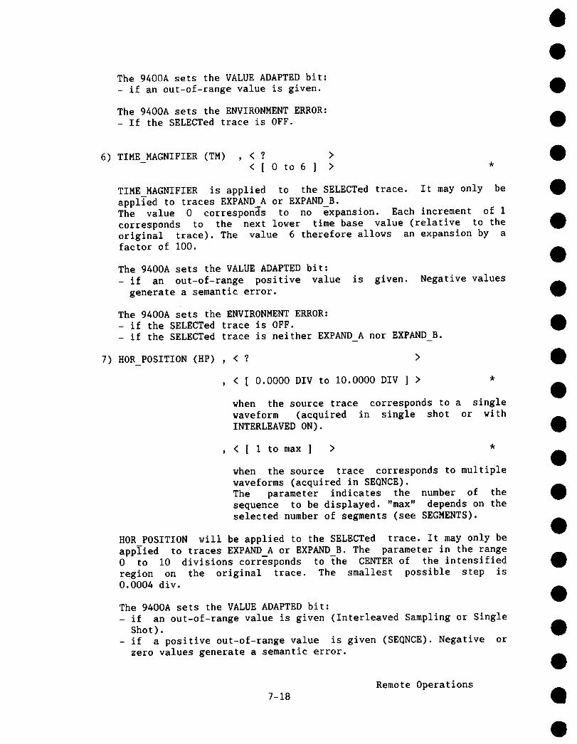
The 9400A sets the VALUE ADAPTED bit:- if an out-of-range value is given.
The 9400A sets the ENVIRONMENT ERROR:- If the SELECTed trace is OFF.
6) TIME MAGNIFIER (TM) , < ? < [ 0 to6 ] >
TIME MAGNIFIER is applied to the SELECTed trace. It may only beapplTed to traces EXPAND A or EXPAND B.The value 0 corresponds to no expansion. Each increment of Icorresponds to the next lower time base value (relative to theoriginal trace). The value 6 therefore allows an expansion by factor of I00.
The 9400A sets the VALUE ADAPTED bit:- if an out-of-range positive value
generate a semantic error.
is given. Negative values
The 9400A sets the ENVIRONMENT ERROR:- if the SELECTed trace is OFF.- if the SELECTed trace is neither EXPAND A nor EXPAND B.
7) HOR POSITION (HP) , < >
, < [ 0.0000 DIV to i0.0000 DIV ] >
when the source trace corresponds to a singlewaveform (acquired in single shot or withINTERLEAVED ON).
, < [ 1 to max ] >
when the source trace corresponds to multiplewaveforms (acquired in SEQNCE).The parameter indicates the number of thesequence to be displayed. "max" depends on theselected number of segments (see SEGMENTS).
HOR POSITION will be applied to the SELECTed trace. It may only beapplied to traces EXPAND A or EXPAND B. The parameter in the range0 to I0 divisions corresponds to The CENTER of the intensifiedregion on the original trace. The smallest possible step is0.0004 div.
The 9400A sets the VALUE ADAPTED bit:- if an out-of-range value is given (Interleaved Sampling or Single
Shot).- if a positive out-of-range value is given (SEQNCE). Negative
zero values generate a semantic error.
7-18Remote Operations
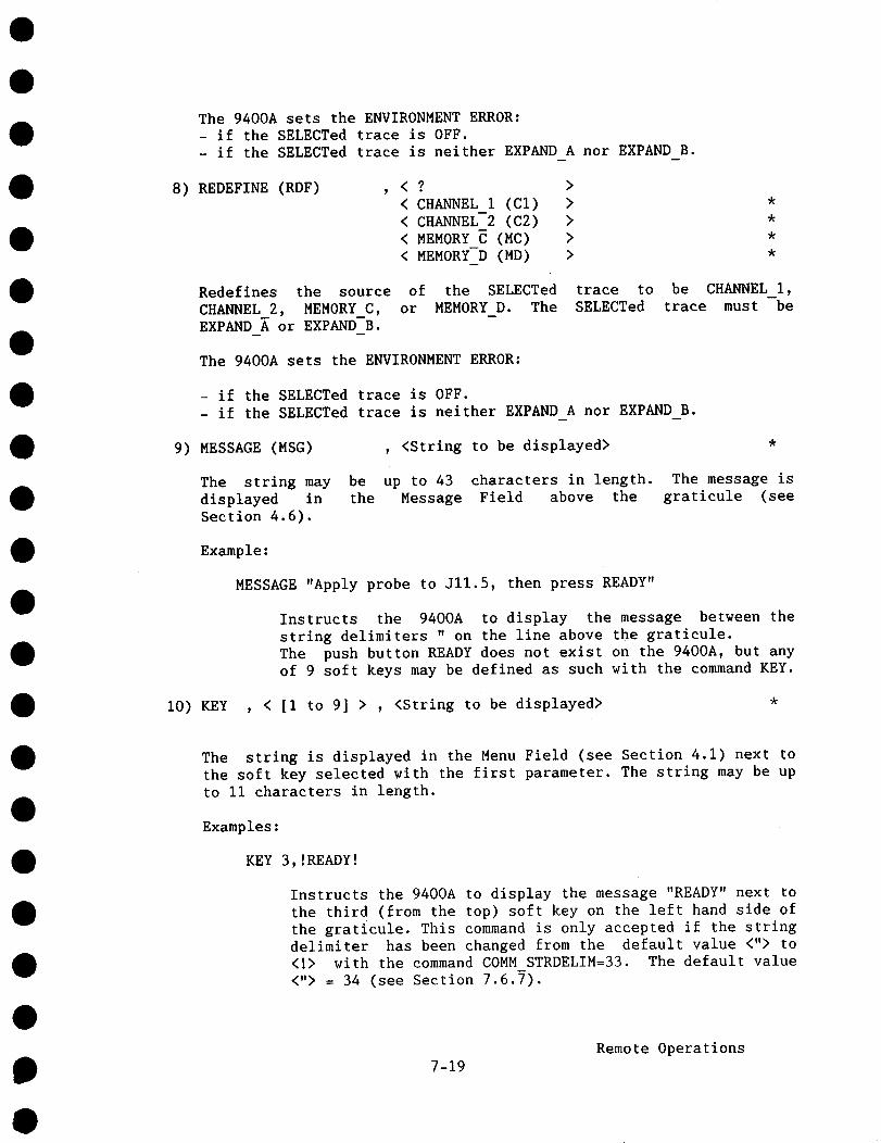
The 9400A sets the ENVIRONMENT ERROR:- if the SELECTed trace is OFF.- if the SELECTed trace is neither EXPAND A nor EXPAND B.
8) REDEFINE (RDF) , < ? >< CHANNEL I (Cl) > *< CHANNEL-2 (C2) > *< MEMORY C (MC) > *< MEMORY-D (MD) > *
Redefines the source of the SELECTed trace toCHANNEL 2, MEMORY_C, or MEMORY_D. The SELECTedEXPAND A or EXPAND B.
be CHANNEL i,trace must be
The 9400A sets the ENVIRONMENT ERROR:
- if the SELECTed trace is OFF.- if the SELECTed trace is neither EXPAND A nor EXPAND B.
9) MESSAGE (MSG) , <String to be displayed>
The string may be up to 43 characters in length. The message isdisplayed in the Message Field above the graticule (see
Section 4.6).
Example:
MESSAGE "Apply probe to Jll.5, then press READY"
Instructs the 9400A to display the message between thestring delimiters " on the line above the graticule.The push button READY does not exist on the 9400A, but anyof 9 soft keys may be defined as such with the command KEY.
i0) KEY , < [I to 9] > , <String to be displayed>
The string is displayed in the Menu Field (see Section 4.1) next the soft key selected with the first parameter. The string may be upto Ii characters in length.
Examples:
KEY 3,!READY!
Instructs the 9400A to display the message "READY" next tothe third (from the top) soft key on the left hand side the graticule. This command is only accepted if the stringdelimiter has been changed from the default value <"> to<!> with the command COMM STRDELIM=33. The default value<"> = 34 (see Section 7.6.7).
7-19Remote Operations

KEY l, "Restart"
Instructs the 9400A to display the message "Restart" nextto the first soft key. Here, the default string delimiteris used.
11) SCREEN (SCR) , <? >< REMOTE (RM) *< LOCAL (LC) *
or
SCREEN (SCR) , < ON **< OFF > **
or
SCREEN (SCR) , < INTENSITY (INT) > , [0 to **< GRID INTENSITY (GI)> **
"?" allows the user to know the status of the screen.
"REMOTE" and "LOCAL" select the control mode of the screen.When the 9400A is set to REMOTE, the screen remains under LOCALcontrol allowing the operator to adjust the display intensity. Thescreen itself must be put into the REMOTE state using the commandSCREEN (SCR) , <ON> before the commands marked with "**" are valid.
"ON" and "OFF" turn the screen ON an OFF respectively.
When the 9400A is being used to capture transients automaticallywithout a user looking at the display, the display may be turnedoff. This improves the response time of the instrument since displaygeneration, which may take up to I00 msec, is suppressed.
"INTENS" and "GRID INT" set the display intensity.
The 9400A sets the VALUE ADAPTED bit:- if a value greater than 170 is given.
7.6.4 Plotter Commands
i) PLOTTER (PT)
or
PLOTTER (PT)
, <? >
, <name> , <port> , <speed> , <pens>
7-20Remote Operations

<name> = < GRAPHTEC (GR) >< HEWLETT PACKARD (HP) >< PHILIPS (PH) >< TEKTRONIX (TEK) >
<port> = < RS232 (RS) < GPIB (SP)
<speed> < NORMAL SPEED (NS) < LOW SPEED (LS)
<pens> = [ 1 to 9 ]
Configures the 9400A for a predefined plotter.
Examples:
PLOTTER HP,RS,NS,2
Configures the 9400A for a Hewlett-Packard plotter,connected to the RS-232-C plotter port, running at normalspeed, with 2 pens. This is how the 9400A must beconfigured for the HP7470 and HP7475 or compatibleplotters.
PT,GR,GP,LS,4
Configures the 9400A for a Graphtec FP5301 or compatibleplotter, connected through GPIB, running at low speed (forplotting on transparencies), with 4 pens.
2) PLOT SIZE (PS) , <? >< A5 > *< A4 > *< A3 > *
Configures the 9400A to plot onto a predefined paper size.
AS=A4=A3 =
148 mm by 210 mm, compatible with U.S. 5 1/2" by 8 1/2"210 mm by 297 mm, compatible with U.S. 8 1/2" by II"297 mm by 420 mm, compatible with U.S. ii" by 17"
or
PLOT SIZE (PS) , NON STANDARD (NSTD) , <grid> , <x> ,
Configures the 9400A to plot onto a non-standard paper size.
<grid> = [ 00.0 MM to 99.9 MM ]
7-21Remote Operations

<x> = [ 0 MM to 999 MM ]
<y> [ 0 MM to 999 MM ]
<grid> is the size (length of a side) of the standard squarewithin the 8 times I0 squares grid.<x>,<y> are the positions of the lower left hand corner of thegraticule with respect to the origin of the plotter.
The 9400A sets the VALUE ADAPTED bit:- if an out-of-range positive value
generate a semantic error.
is given. Negative values
3) SCREEN DUMP (SD) *
Instructs the 9400A to dump the screen display onto the plotter.
4) TRANSMIT (TX) , <String to be transmitted to the plotter>
Instructs the 9400A to transmit a character string to the plotter.The string may be up to 43 characters in length and may includecommands such as "paper advance" or "print string". This enables theuser to add comments to a plot, or generate multiple plots by remotecontrol.
The 9400A sets the ENVIRONMENT ERROR:- if the 9400A is controlled through GPIB and if the plotter access
port is the GPIB port.
7.6.5 Transfer Comm~,ds
i) STORE (STO) , [ 1 to
instructs the 9400A to store the current front panel configurationin one of 7 non-volatile storage areas for later recall.
or
STORE (STO) , < CHANNEL 1 (CI) > , < MEMORY C (MC) < CHANNEL-2 (C2) > < MEMORY-D (MD)
instructs the 9400A to store the waveform and the waveformdescriptor of either Channel 1 or 2 into reference memories C or D.
Notes:If the 9400A receives a command to store Channel 1 or 2 while it isacquiring data, the execution of the command is delayed until thetrigger has arrived.
7-22Remote Operations

No message will be displayed on the screen when the operation isperformed.
2) RECALL (REC) , [ 1 to
instructs the 9400A to recall one of 8 front-panel configurationsstored in non-volatile memory. The value "8" corresponds to thedefault setup.
3) SETUP (SU)
or
SETUP (SU) *
The first form permits the complete setup to be read in internaldata representation. Transmission format depends on the selectedforms by the COMM FORMAT command. The setup data block correspondsto 257 binary bytes.
The second form permits setup data to be sent to the 9400A in thesame form as they were read from the 9400A. This command must beterminated with <END>, i.e. it must be the last of a list ofcommands. The data transferred to the 9400A must be contained in aseparate block (see Section 7.5).
Note:The serial port parameters can not be transmitted. In particular, ifthe transfers are by RS-232-C, modification of the serial portparameters by this command would bring about some strange results.
The 9400A sets the VALUE ADAPTED bit:- if a data value in the block is incorrect. The DEFAULT setup will
be used in this case.
The 9400A sets the INVALID BLOCK ERROR:- if the received block(s) is incorrect.
4) READ (RD) , < CHANNEL I.DESC< CHANNEL-2.DESC< MEMORY C.DESC< MEMORY D.DESC
(CI.DE) (C2.DE) (MC.DE) (MD.DE)
transfer the descriptor of the indicated waveform from the 9400A tothe host computer. See Section 7.7 for the format of this datablock.
or
7-23Remote Operations

READ (RD) , < CHANNEL 1.DATA< CHANNEL 2.DATA< MEMORY C.DATA< MEMORY-D.DATA
(CI.DA) > , <Parameter list>(C2.DA) >(MC.DA) (MD.DA)
<Parameter list> = <intval> , <# values> , <addr> , <sweep #>
transfer the data values of the indicated waveform from the 9400A tothe host computer. An explanation of the optional parameter list isgiven below.
or
READ (RD) , < CHANNEL 1.TIME< CHANNEL-2.TIME< MEMORY C.TIME< MEMORY-D.TIME
(CI.TI) (C2.TI) (MC.TI) (MD.TI)
transfer the trigger time(s) of the indicated waveform from the9400A to the host computer. See Section 7.8 for the format of thisdata block.
or
READ (RD) , < CHANNEL I.* (CI.*) > , <Parameter list>< CHANNEL-2.* (C2.*) < MEMORY C.* (MC.*) < MEMORY-D.* (MD.*)
transfer ALL visible data of the indicated waveform from the 9400Ato the host computer. Data are transferred in the order descriptor,data, time(s).
<Parameter list> = <intval> , <# values> , <addr> , <sweep #>
<intval> = [ 1 to 16000 ] Interval between data points to beread, for example:
I = read all points4 = leave out 3 of 4 data values
<# values>= [ 0 to 32000 ] Number of data values to read
<addr> = [ -32000 to 32000 ] Address of first datarelative to the left handthe screen
pointside of
<sweep #> = [ 0 to 250 ] Sweep number in SEQNCEnumbered from1 to max. # sweeps0 = read all sweeps
waveforms,
7-24Remote Operations

The parameter list is optional. Any omitted parameter is set to adefault value:
<intval><# values><addr><sweep #>
= i, i.e. leave no values out= # values on the screen= address of left-most value on the screen= 0, i.e. read all sweeps
Thus, the omission of all parameters results in all the data valueson the screen being read. A detailed explanation of the dataaddressing conventions is given in Section 7.9.
If the user does not specify the number of data values, READ DATAtransfers are executed over the number of data values displayed onscreen + i, i.e. if the screen shows nominally 25000 data values,25001 values are transferred.
Data formats:
- The descriptor (.DESC), the data (.DATA) and the time(s)(.TIME) are each transmitted as a single block unless maximum block size has been specified with the commandCOMM BLOCKSIZE.
- When all data are read (.*), they are transmitted as threeblocks in the order: descriptor, data, time(s).
- When all sweeps of a SEQNCE data record are read (sweep # 0), each sweep is transmitted as a separate block.
- The parameter <# values> applies to the number of datavalues per sweep in the case of SEQNCE data.
Note:If the 9400A receives a command to read CHANNEL I or CHANNEL 2 whileit is acquiring data, the execution of the command will be-delayeduntil the TRIGGER has arrived.
The 9400A sets the VALUE ADAPTED bit:- if <intval> is greater than 16000 (it is adapted to 16000).- if <# values> corresponds to too large a value (it is adapted to
the number corresponding to the last accessible value).- if <addr> is out of range (it is adapted to the nearest legal
address).- if <sweep #> is higher that the selected number of sweeps (it is
adapted to the last sweep number).
7-25Remote Operations

Examples:
READ,CI.DE
READ,MC.DA
READ,MC.DA,,,-7000
READ,CI.DA,5,100,1000
READ,MD.DA,,,,5
READ,CHANNEL 2.*
Instructs the 9400A to transmit thewaveform descriptor of Channel 1 in theformat described in Section 7.7. If the9400A is armed and waiting for atrigger, the execution is deferred untilthe waveform is acquired.
Instructs the 9400A to transmit all datavalues of Memory C which would appear onthe screen, but no descriptor or triggertime(s).
Instructs the 9400A to transmit all datapoints of Memory C, starting -7000(invisible) points before the left handside of the screen, up to the last valueat the right hand side.
Instructs the 9400A to transmit I00 datavalues of Channel i, starting i000
values to the right of ~e beginning ofthe screen. Only every 5 data value istransmitted, i.e. 4 out of 5 values areomitted.
Instructs the 9400A to transmit all datavalues of sweep #5 from the SEQNCE datarecord in memory D. If memory D is not aSEONCE record, the last parameter isignored, and the command would beinterpreted as READ,MD.DA, resulting inthe transmission of all (visible) dataof the memory D.
Instructs the 9400A to transmit thewaveform descriptor, data and time(s) Channel 2. This is the most complete(and safest) way to archive the visiblepart of a waveform. The host computercan restore the complete waveform inmemories C or D with the command WRITEMC.*, followed by the transmission ofthe data records.
7-26Remote Operations

READ,CHANNEL_2.*,,,-32000 Instructs the 9400A to transmit thewaveform descriptor, data and time(s) Channel 2, including all invisible datavalues on the left-hand side of thescreen. The address -32000 is usuallyout of range, but the 9400Aautomatically adapts to the closestlegal value. This complete data recordis restored in memory C with the commandWRITE MC.*,,,-32000.
5) WRITE (WT) , < MEMORY C.DESC (MC.DE) *< MEMORY-D.DESC (MD.DE) *
transfer the waveform descriptor from the host computer to theindicated memory location of the 9400A. This command must befollowed by the descriptor block(s). The 9400A checks the limits each parameter transmitted. If any value is out of range, or thenumber of values transmitted is incorrect, the entire descriptorblock is considered invalid and is discarded.
WRITE (WT) , < MEMORY C.DATA (MC.DA) > , <Param.list> *< MEMORY-D.DATA (MD.DA) *
<Parameter list> = <intval> , <# values> , <addr> , <sweep #>
transfer data values from the host computer to the indicatedmemory location of the 9400A. This command must be followed by thedata value block(s). See the READ command for an explanation <Parameter list>.
or
WRITE (WT) , < MEMORY C.TIME (MC.TI) *< MEMORY-D.TIME (MD.TI) ,
transfer trigger time(s) from the host computer to the indicatedmemory location of the 9400A. This command must be followed by thetrigger time block. If the number of values transmitted isincorrect, the entire block is discarded.
When transferring WRITE DATA without specifying the number of datavalues, the nominal number + i data values must be sent to the 9400A(25000 + 1 data values for example). This additional value may needed for the generation of the last displayed point at the righthand side of the screen.
or
WRITE (WT) , < MEMORY C.* (MC.*) > , <Parameter list> *< MEMORY-D.* (MD.*) *
Remote Operations7-27
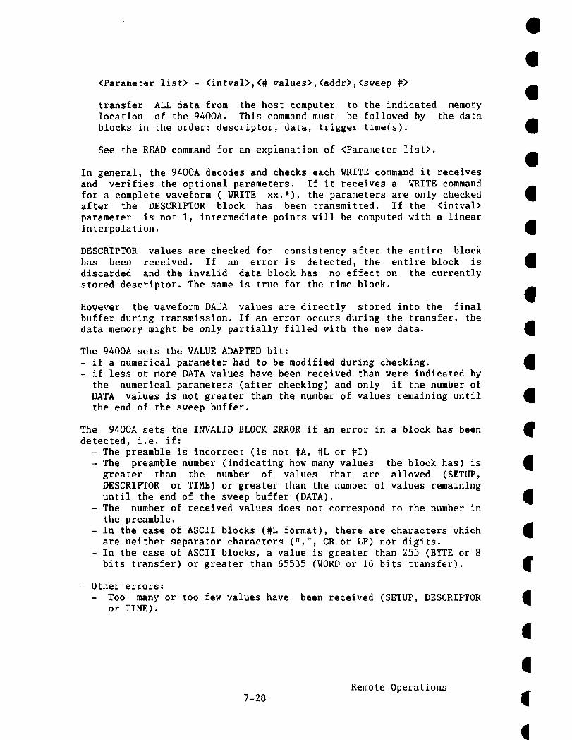
<Parameter llst> = <intval>,<# values>,<addr>,<sweep #>
transfer ALL data from the host computer to the indicated memorylocation of the 9400A. This command must be followed by the datablocks in the order: descriptor, data, trigger time(s).
See the READ command for an explanation of <Parameter list>.
In general, the 9400A decodes and checks each WRITE command it receivesand verifies the optional parameters. If it receives a WRITE commandfor a complete waveform ( WRITE xx.*), the parameters are only checkedafter the DESCRIPTOR block has been transmitted. If the <intval>parameter is not I, intermediate points will be computed with a linearinterpolation.
DESCRIPTOR values are checked for consistency after the entire blockhas been received. If an error is detected, the entire block isdiscarded and the invalid data block has no effect on the currentlystored descriptor. The same is true for the time block.
However the waveform DATA values are directly stored into the finalbuffer during transmission. If an error occurs during the transfer, thedata memory might be only partially filled with the new data.
The 9400A sets the VALUE ADAPTED bit:- if a numerical parameter had to be modified during checking.- if less or more DATA values have been received than were indicated by
the numerical parameters (after checking) and only if the number DATA values is not greater than the number of values remaining untilthe end of the sweep buffer.
The 9400A sets the INVALID BLOCK ERROR if an error in a block has beendetected, i.e. if:
- The preamble is incorrect (is not #A, #L or #I)- The preamble number (indicating how many values the block has)
greater than the number of values that are allowed (SETUP,DESCRIPTOR or TIME) or greater than the number of values remaininguntil the end of the sweep buffer (DATA).
- The number of received values does not correspond to the number inthe preamble.
- In the case of ASCII blocks (#L format), there are characters whichare neither separator characters (",", CR or LF) nor digits.
- In the case of ASCII blocks, a value is greater than 255 (BYTE or bits transfer) or greater than 65535 (WORD or 16 bits transfer).
- Other errors:- Too many or too few values have
or TIME).been received (SETUP, DESCRIPTOR
7-28Remote Operations

READ,CHANNEL 2.*,,,-32000 Instructs the 9400A to transmit thewaveform descriptor, data and time(s) Channel 2, including all invisible datavalues on the left-hand side of thescreen. The address -32000 is usuallyout of range, but the 9400Aautomatically adapts to the closestlegal value. This complete data recordis restored in memory C with the commandWRITE MC.*,,,-32000.
5) WRITE (WT) , < MEMORY C.DESC (MC.DE) *< MEMORY-D.DESC (MD.DE) *
transfer the waveform descriptor from the host computer to theindicated memory location of the 9400A. This command must befollowed by the descriptor block(s). The 9400A checks the limits each parameter transmitted. If any value is out of range, or thenumber of values transmitted is incorrect, the entire descriptorblock is considered invalid and is discarded.
WRITE (WT) , < MEMORY C.DATA (MC.DA) > , <Param.list> *< MEMORY-D.DATA (MD.DA) *
<Parameter list> = <intval> , <# values> , <addr> , <sweep #>
transfer data values from the host computer to the indicatedmemory location of the 9400A. This command must be followed by thedata value block(s). See the READ command for an explanation <Parameter list>.
or
WRITE (WT) , < MEMORY C.TIME (MC.TI) *< MEMORY-D.TIME (MD.TI) *
transfer trigger time(s) from the host computer to the indicatedmemory location of the 9400A. This command must be followed by thetrigger time block. If the number of values transmitted isincorrect, the entire block is discarded.
When transferring WRITE DATA without specifying the number of datavalues, the nominal number + I data values must be sent to the 9400A(25000 + 1 data values for example). This additional value may needed for the generation of the last displayed point at the righthand side of the screen.
or
WRITE (WT) , < MEMORY C.* (MC.*) > , <Parameter list> *< MEMORY-D.* (MD.*) *
7-27Remote Operations
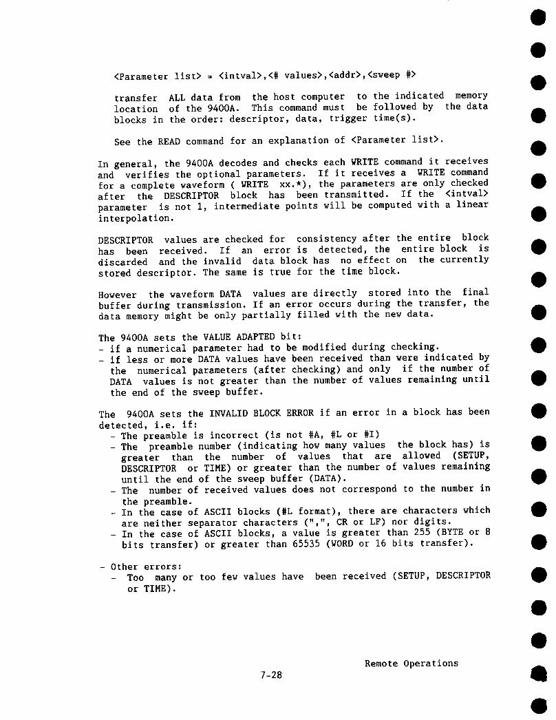
<Parameter list> = <intval>,<# values>,<addr>,<sweep #>
transfer ALL data from the host computer to the indicated memorylocation of the 9400A. This command must be followed by the datablocks in the order: descriptor, data, trigger time(s).
See the READ command for an explanation of <Parameter list>.
In general, the 9400A decodes and checks each WRITE command it receivesand verifies the optional parameters. If it receives a WRITE commandfor a complete waveform ( WRITE xx.*), the parameters are only checkedafter the DESCRIPTOR block has been transmitted. If the <intval>parameter is not i, intermediate points will be computed with a linearinterpolation.
DESCRIPTOR values are checked for consistency after the entire blockhas been received. If an error is detected, the entire block isdiscarded and the invalid data block has no effect on the currentlystored descriptor. The same is true for the time block.
However the waveform DATA values are directly stored into the finalbuffer during transmission. If an error occurs during the transfer, thedata memory might be only partially filled with the new data.
The 9400A sets the VALUE ADAPTED bit:- if a numerical parameter had to be modified during checking.- if less or more DATA values have been received than were indicated by
the numerical parameters (after checking) and only if the number DATA values is not greater than the number of values remaining untilthe end of the sweep buffer.
The 9400A sets the INVALID BLOCK ERROR if an error in a block has beendetected, i.e. if:
- The preamble is incorrect (is not #A, #L or #I)- The preamble number (indicating how many values the block has)
greater than the number of values that are allowed (SETUP,DESCRIPTOR or TIME) or greater than the number of values remaininguntil the end of the sweep buffer (DATA).
- The number of received values does not correspond to the number inthe preamble.
- In the case of ASCII blocks (#L format), there are characters whichare neither separator characters (",", CR or LF) nor digits.
- In the case of ASCII blocks, a value is greater than 255 (BYTE or bits transfer) or greater than 65535 (WORD or 16 bits transfer).
- Other errors:- Too many or too few values have
or TIME).
been received (SETUP, DESCRIPTOR
7-28Remote Operations

READ,CHANNEL 2.*,,,-32000 Instructs the 9400A to transmit thewaveform descriptor, data and time(s) Channel 2, including all invisible datavalues on the left-hand side of thescreen. The address -32000 is usuallyout of range, but the 9400Aautomatically adapts to the closestlegal value. This complete data recordis restored in memory C with the commandWRITE MC.*,~,-32000.
5) WRITE (WT) , < MEMORY C.DESC (MC.DE) *< MEMORY D.DESC (MD.DE) *
transfer the waveform descriptor from the host computer to theindicated memory location of the 9400A. This command must befollowed by the descriptor block(s). The 9400A checks the limits each parameter transmitted. If any value is out of range, or thenumber of values transmitted is incorrect, the entire descriptorblock is considered invalid and is discarded.
WRITE (WT) , < MEMORY C.DATA (MC.DA) > , <Param.list> *< MEMORY D.DATA (MD.DA) *
<Parameter list> = <intval> , <# values> , <addr> , <sweep #>
transfer data values from the host computer to the indicatedmemory location of the 9400A. This command must be followed by thedata value block(s). See the READ command for an explanation <Parameter list>.
or
WRITE (WT) , < MEMORY C.TIME (MC.TI) *< MEMORY D.TIME (MD.TI) *
transfer trigger time(s) from the host computer to the indicatedmemory location of the 9400A. This command must be followed by thetrigger time block. If the number of values transmitted isincorrect, the entire block is discarded.
When transferring WRITE DATA without specifying the number of datavalues, the nominal number + I data values must be sent to the 9400A(25000 + 1 data values for example). This additional value may needed for the generation of the last displayed point at the righthand side of the screen.
or
WRITE (WT) , < MEMORY C.* (MC.*) > , <Parameter list> *< MEMORY D.* (MD.*) *
7-27Remote Operations

<Parameter list> = <intval>,<# values>,<addr>,<sweep #>
transfer ALL data from the host computer to the indicated memorylocation of the 9400A. This command must be followed by the datablocks in the order: descriptor, data, trigger time(s).
See the READ command for an explanation of <Parameter list>.
In general, the 9400A decodes and checks each WRITE command it receivesand verifies the optional parameters. If it receives a WRITE commandfor a complete waveform ( WRITE xx.*), the parameters are only checkedafter the DESCRIPTOR block has been transmitted. If the <intval>parameter is not i, intermediate points will be computed with a linearinterpolation.
DESCRIPTOR values are checked for consistency after the entire blockhas been received. If an error is detected, the entire block isdiscarded and the invalid data block has no effect on the currentlystored descriptor. The same is true for the time block.
However the waveform DATA values are directly stored into the finalbuffer during transmission. If an error occurs during the transfer, thedata memory might be only partially filled with the new data.
The 9400A sets the VALUE ADAPTED bit:- if a numerical parameter had to be modified during checking.- if less or more DATA values have been received than were indicated by
the numerical parameters (after checking) and only if the number DATA values is not greater than the number of values remaining untilthe end of the sweep buffer.
The 9400A sets the INVALID BLOCK ERROR if an error in a block has beendetected, i.e. if:
- The preamble is incorrect (is not #A, #L or #I)- The preamble number (indicating how many values the block has)
greater than the number of values that are allowed (SETUP,DESCRIPTOR or TIME) or greater than the number of values remaininguntil the end of the sweep buffer (DATA).
- The number of received values does not correspond to the number inthe preamble.
- In the case of ASCII blocks (#L format), there are characters whichare neither separator characters (",", CR or LF) nor digits.
- In the case of ASCII blocks, a value is greater than 255 (BYTE or bits transfer) or greater than 65535 (WORD or 16 bits transfer).
- Other errors:- Too many or too few values have
or TIME).been received (SETUP, DESCRIPTOR
Remote Operations7-28

- The string beginning with a character other than "#" is receivedwhile the 9400A expects a block.Such an error happens if the 9400A, previously configured to workwithout the END block (#I), receives less data than expected,followed by a command.
- Too many blocks have been received.
If the 9400A detects an error while receiving dataremaining values in the block, as well as the followingpurged until END block (#I) or a command is received.
blocks, anyblocks are
When a command is received instead of a block, block transfer isaborted, but the command will be decoded like any other command.
When a block is received without being preceded by the WRITE command,the block will be purged and syntax error ii will be produced (InvalidHeader).
Note: Block data must end with a legal Trailer such as <CR>, <LF> or<CRLF>.
6) INSPECT (INS) , < CHANNEL 1.LIMIT< CHANNEL-2.LIMIT< MEMORY C.LIMIT< MEMORY-D.LIMIT
(CI.LI) (C2.LI) (MC.LI) (MD.LI)
instructs the 9400A to return a character string containing thelower and upper address limits of the current waveform,
or
INSPECT (INS) , < CHANNEL I.NSWEEPS< CHANNEL-2.NSWEEPS< MEMORY C.NSWEEPS< MEMORY-D.NSWEEPS
(CI.NS) (C2.NS) (MC.NS) (MD.NS)
instructs the 9400A to return a character string containingnumber of sweeps (in averaging and extrema),
the
or
INSPECT (INS) , < MEMORY C.INTVAL< MEMORY-D.INTVAL
(MC.IV) (MD.IV)
instructs the 9400A to return a character string, containing theinterval between data points used by a waveform processing function.This value may be used as the <intval> parameter in the readout ofsuch waveforms if the user wishes to read only the computed datapoints and none of the interpolated points.
Remote Operations7-29
7.6.6 Other Remote Commands
1) CALIBRATE (CAL)
forces the 9400A to do a calibration of the interpolator and of bothinput channels at the current gain and bandwidth settings.
or
CALIBRATE (CAL) , <? >< ON > *< OFF > *
allows(OFF),Sectionitself.
automatic calibration (ON), disables automatic calibrationor queries the state of the automatic calibration. See9.4 for the conditions under which the 9400A calibrates
2) PROBE CAL (PC) , < AC >< DC >
, [ 0.000 V to 5.000 V ]
This command permits generation of a square signal (AC) with period of 1.024 msec, or a continuous (DC) level at the specifiedvoltage at the probe test output.
When the 9400A returns to LOCAL, the default calibrator signal of 1V (AC) is generated.
The 9400A sets the VALUE ADAPTED bit:- if a positive out-of-range value is given.
3) AUTO STORE (AS) , ? ><[0toS] >
This command allows the user to query the 9400A on its AUTOSTOREstate or setting of the AUTOSTORE mode:
O:
i:2:3:4:5:
AUTOSTORE offautomatic storage of CHANNEL 1 into MEMORY Cautomatic storage of CHANNEL-1 into MEMORY-Dautomatic storage of CHANNEL-2 into MEMORY-Cautomatic storage of CHANNEL-2 into MEMORY-Dautomatic storage of CHANNEL-1 into MEMORY-Cand of CHANNEL 2 into MEMORY-D
Remote Operations7-30

4) CALL HOST (CH) , < < ON >< OFF >
This command may be executed even while the 9400A is in LOCAL. Whenthe CALL HOST mode is set, the 9400A (only while it is in LOCAL)displays -the message "Call Host" next to the soft key #7 of theMain Menu. Whenever this soft key is pressed it will generate aservice request (SRO), provided that the masks of status byte 3 andstatus byte 1 are correctly set (see Section 7.6.8). The purpose this command is to allow the operator in an ATE setup (AutomaticTest Engineering) to call the host computer even while the 9400A isin LOCAL mode, i.e. while the operator is permitted to change the9400A front panel settings.
5) IDENTIFY (ID)
Request for identification message. "?" may be omitted.The 9400A will send the message "LECROY 9400A - V xxxxxx", where"xxxxxx" is the software version number.
6) WAIT
When the 9400A is acquiring a signal, the WAIT command stops anycommand interpretation until the oscilloscope has been triggered.
7.6.7 Communication Format Command
i) COMM HEADER (CHDR) , < OFF >< SHORT (SHO) < LONG (LG)
Defines the header format in the 9400A character strings in responseto queries. Options are no header, short or long formats. Thedefault is SHORT. When the header is OFF, the suffixes of thedimensioned parameters are also suppressed.
2) COMM TRAILER (CTRL) , < CRLF >< CR >< LF >< OFF >
Defines the trailer format in the 9400A character strings inresponse to queries. OFF is only possible in RS-232-C control. Thedefault is CRLF.
Note:In remote control through GPIB, the last character is sent with theE0I line set.
Remote Operations7-31
The 9400A sets the ENVIRONMENT ERROR:- if command is CTRL OFF, while controlling via GPIB.
3) COMM HELP (CHLP) , < OFF >< REM PORT (RPO) < PLOT PORT (PeO)
Allows a HELP feature for the setup of remote control programs to beturned on. When the HELP feature has been turned on, the 9400Atransmits character strings reflecting the message exchange betweenthe host computer and the oscilloscope to the REMOTE or to thePLOTTER RS-232-C ports. These HELP messages can be viewed on anormal display terminal.
4) COMM FORMAT (CFMT),A, <BYTE><WORD>
Or
COMM FORMAT (CFMT),L, <BYTE>,<HEX><WORD>,<UNSIGNED_FIXED(UFIX)>
or
COMM_FORMAT(CFMT),L, <BYTE>,<UNSIGNED_SHORT(USHO)>,<COMMA><WORD>, " " " <CR>
<LF><CRLF>
Selects a block transfer format, as described in Section 7.5. InRS-232-C remote control, only format L is available.
BYTE is for 8-bit data.
WORD is for 16-bit data. This format is normally used for 16-bitdata being read from Memory C, Memory D, Function E or Function F.Raw data in Channel 1 and Channel 2 are always 8-bit data. It ispossible to read raw or processed data as 16-bit words. Raw datahave the measured 8-bit value in the most significant byte(transmitted first), and zero in the least significant byte(transmitted after).
HEX results in 2 hexadecimal digits for each 8-bit value and in 4hexadecimal digits for 16-bit value.
UNSIGNED FIXED uses 3 digits for BYTE data and 5 digits for WORDdata.
UNSIGNED SHORT uses only as many digits as required but separatesdata values with a sign. The last parameter selects the separatorbetween numbers.The default is <COMMA>.
7-32Remote Operations
Example:
With "COMM FORMAT L,BYTE,UNSIGNED_SHORT,CRLF", a block will be:
#L2123
34
Whereas with "COMM_FORMAT L,BYTE,UNSIGNED_SHORT" it is:
#L,2,123,34
The 9400A sets the ENVIRONMENT ERROR:- if the A format is selected while the 9400A is controlled through
RS-232-C.
5) COMM BLOCKSIZE (CBLS) -i
The data is transmitted in one block only, andblock (#I) is neither sent nor received.
the END
COMM BLOCKSIZE (CBLS) ,
The data is transmitted in one block only. The END block(#I) will be sent and must be received. This is thedefault block size.
COMM BLOCKSIZE (CBLS) , 40to 320 00 ]
The data is transmitted in one or more blocks. The ENDblock (#I) will be sent and must be received with thepurpose of marking the end of the block transfer.
This command selects the maximum block size for data block transfers(READ,WRITE,SETUP). The specified block size includes all databytes, including preamble and postscript.
The 9400A sets the VALUE ADAPTED bit:- if the numerical parameter is positive but less than 40 (it will
be adapted to 40) or if it is greater than 32000 (it will adapted to 32000).
6) COMM STRDELIM (CSDE) , [ to 127 ]
Defines the ASCII character that the 9400A recognizes as a stringdelimiter. The default is the character <">, whose decimal value is34.
7-33Remote Operations
7) COMM PROMPT (CPRM) , < OFF - < prompt string >
Defines the 9400A prompt string which may be up to I0 characterslong. The default is OFF. This feature simplifies interactiveprogramming of the 9400A. When set, the host computer must read the9400A after every command, even when no response is normallyexpected. The 9400A responds either with the prompt string alone orwith its response, followed by the prompt, indicating that it isready for another command.
Summary of COMM default values:
COMM HEADERCOMM-TRAILER :COMM-HELPCOMM-FORMAT
COMM BLOCKSIZE :COMM-STRDELIM :COMM-PROMPT
SHORTCRLFOFFGPIB: A format, BYTERS232: L format, BYTE, UFIX,COMMA0" (Decimal value: 34)OFF
7.6.8 Status Byte and Mask Register Commands
The 9400A contains a Main Status Byte (STB I) and 5 additional statusbytes, numbered from 2 to 6. Each status byte has an associated maskregister, also numbered from i to 6. The purpose of the status bytes isto keep track of the internal conditions of the 9400A. The user can use2 methods of staying informed:
- The status bytes can be read at any time, one by one or in asingle block, with or without simultaneous clearing. This methodignores all mask registers. The host computer program is requiredto continue testing a status bit of interest, e.g., bit #0 of theOPERATION COMPLETE status byte (STB 5) after the SCREEN_DUMPcommand.
- The user can configure the 9400A to generate an interrupt to thehost computer upon the occurrence of one or several conditions.The user must demask the bit(s) of the status byte whichcorresponds to the condition(s), by setting l’s into thecorresponding bit of the mask in question. In addition, thecorresponding bit in the Main Status Byte (STB I) must also demasked in order to allow the generation of the Service Request.This method is much more efficient timewise, but requires a morecomplex setup. In addition, the host computer must be configuredto handle an interrupt by the GPIB SRQ-line. See Section 7.11 formore explanations and examples.
7-34Remote Operations
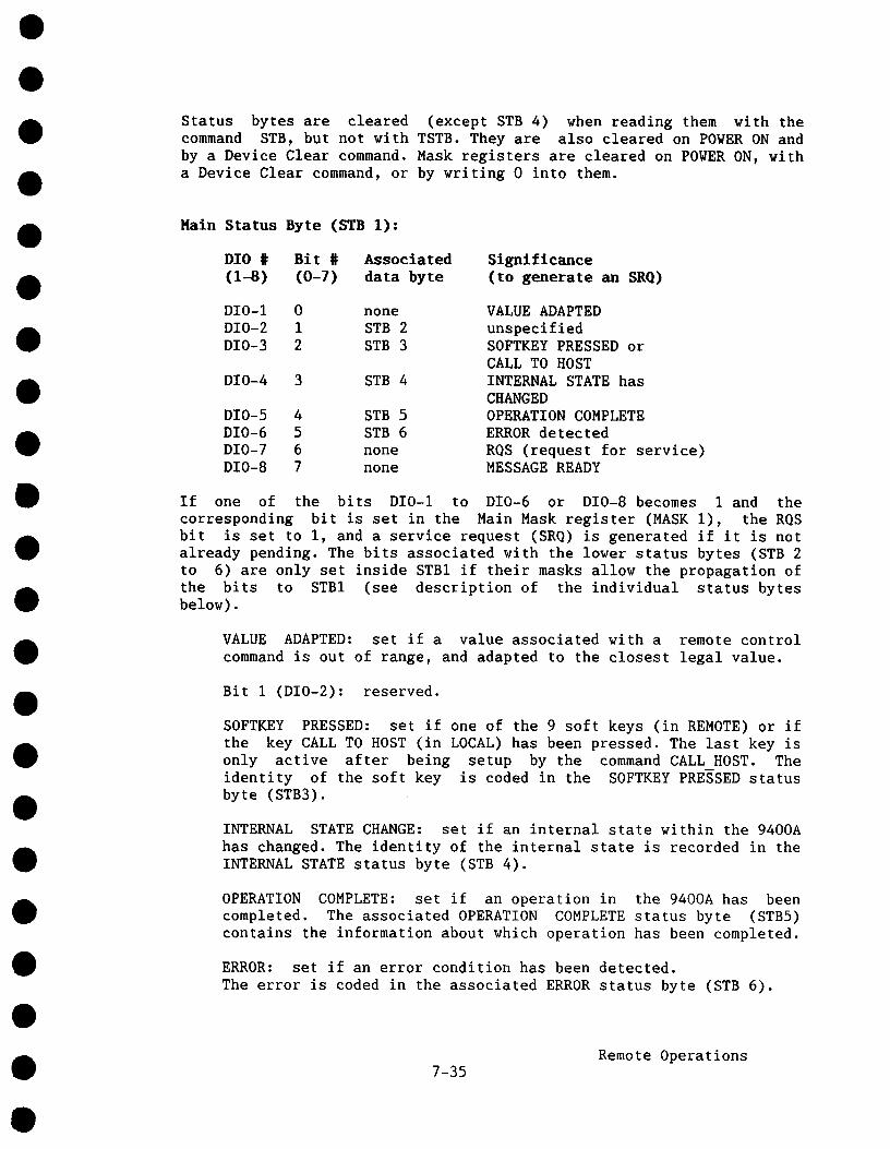
Status bytes are cleared (except STB 4) when reading them with thecommand STB, but not with TSTB. They are also cleared on POWER ON andby a Device Clear command. Mask registers are cleared on POWER ON, witha Device Clear command, or by writing 0 into them.
Main Status Byte (STB 1):
DI0 # Bit # Associated(1-8) (0-7) data
Significance(to generate an SRQ)
DIO-I 0 noneDIO-2 1 STB 2DIO-3 2 STB 3
DIO-4 3 STB 4
DIO-5 4 STB 5DIO-6 5 STB 6DIO-7 6 noneDIO-8 7 none
VALUE ADAPTEDunspecifiedSOFTKEY PRESSED orCALL TO HOSTINTERNAL STATE hasCHANGEDOPERATION COMPLETEERROR detectedRQS (request for service)MESSAGE READY
If one of the bits DIO-I to DIO-6 or DIO-8 becomes 1 and thecorresponding bit is set in the Main Mask register (MASK I), the RQSbit is set to i, and a service request (SRQ) is generated if it is notalready pending. The bits associated with the lower status bytes (STB to 6) are only set inside STBI if their masks allow the propagation ofthe bits to STB1 (see description of the individual status bytesbelow).
VALUE ADAPTED: set if a value associated with a remote controlcommand is out of range, and adapted to the closest legal value.
Bit I (DIO-2): reserved.
SOFTKEY PRESSED: set if one of the 9 soft keys (in REMOTE) or the key CALL TO HOST (in LOCAL) has been pressed. The last key only active after being setup by the command CALL HOST. Theidentity of the soft key is coded in the SOFTKEY PRESSED statusbyte (STB3).
INTERNAL STATE CHANGE: set if an internal state within the 9400Ahas changed. The identity of the internal state is recorded in theINTERNAL STATE status byte (STB 4).
OPERATION COMPLETE: set if an operation in the 9400A has beencompleted. The associated OPERATION COMPLETE status byte (STB5)contains the information about which operation has been completed.
ERROR: set if an error condition has been detected.The error is coded in the associated ERROR status byte (STB 6).
Remote Operations7-35

RQS: GPIB RQS bit, indicating if a service request is pending.
MESSAGE READY: set to indicate that a message is ready fortransmission to the remote controller.
STB 2:
This status byte is unused and has no significance. However, it existsand has an associated mask. The commands STB, MASK and TSTB act on all6 status bytes or masks, including STB 2.
SOFTKEY PRESSED Status Byte (STB 3):
This status byte contains the coded value of the most recently pressedsoft key. Whenever the MASK 3 is non-zero, and the code in STB 3 is setto a non-zero value, the SOFTKEY PRESSED bit (DIO-3) in STB I is set.
Codes:O: No soft key pressed.
i - 9: One of soft keys I - 9 pressed (in REMOTE)I0: CALL TO HOST soft key pressed (in LOCAL)
INTERNAL STATE Status Byte (STB 4):
This status byte contains status bits, reflecting the internal state ofthe 9400A. Since the internal states cannot be directly controlled,reading this byte does NOT reset it. Whenever a bit of this status bytegets set, and the corresponding bit in MASK 4 is also set, the INTERNALSTATE bit (DIO-4) in STB 1 is set.
Bits:O:
1:
2:
3:
TRIGGERED: cleared when the 9400A is armed, i.e.acquiring data, and set when the 9400A is triggered,i.e. not acquiring data.0VERLOADI: set when channel 1 is in overload, resetotherwise.OVERLOAD2: set when channel 2 is in overload, resetotherwise.FIRST SEQNCE sweep triggered
Note:Overloads are cleared by removing the overloading signal from the inputand by returning the input coupling to 50 Q. Overloads never occur with1Mg coupling.
OPERATION COMPLETE Status Byte (STB 5):
This status byte contains status bits reflecting the identity of theoperation which has been completed. Whenever a bit of this status bytegets set, and the corresponding bit in MASK5 is also set, the OPERATIONCOMPLETE bit (DIO-5) in STBI is set.
7-36Remote Operations
t
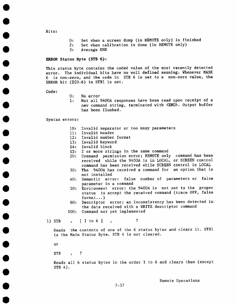
Bits:
O:
2:3:
Set when a screen dump (in REMOTE only) is finishedSet when calibration is done (in REMOTE only)Average END
ERROR Status Byte (STB 6):
This status byte contains the coded value of the most recently detectederror. The individual bits have no well defined meaning. Whenever MASK6 is non-zero, and the code in STB 6 is set to a non-zero value, theERROR bit (DIO-6) in STBI is set.
Code:0:
I:No errorNot all 9400A responses have been read upon receipt of anew command string, terminated with <END>. Output bufferhas been flushed.
Syntax errors:
60:
I00:
i0: Invalid separator or too many parametersII: Invalid header12: Invalid number format13: Invalid keyword14: Invalid block15: 2 or more strings in the same command20: Command permission error; REMOTE only command has been
received while the 9400A is in LOCAL, or SCREEN controlcommand has been received while SCREEN control is LOCAL
30: The 9400A has received a command for an option that isnot installed
40: Semantic error: false number of parameters or falseparameter in a command
50: Environment error: the 9400A is not set to the properstatus to accept the received command (trace OFF, falseformat...)Descriptor error; an inconsistency has been detected inthe data received with a WRITE descriptor commandCommand not yet implemented
i) STB , [ I to 6 ] ?
Reads the contents of one of the 6 status bytes and clears it. STBIis the Main Status Byte. STB 4 is not cleared.
or
STB , ?
Reads all 6 status bytes in the order I to 6 and clears them (exceptSTB 4).
7-37Remote Operations
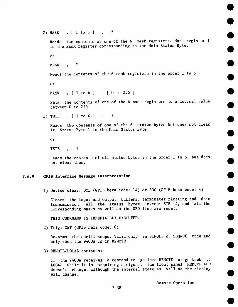
2) MASK , [ 1 to 6 ] ,
Reads the contents of one of the 6 mask registers. Mask register 1is the mask register corresponding to the Main Status Byte.
or
MASK , ?
Reads the contents of the 6 mask registers in the order 1 to 6.
or
MASK
Sets
, [ 1 to 6 ] , [ 0 to 255 ]
the contents of one of the 6 mask registers to a decimal valuebetween 0 to 255.
3) TSTB , [ 1 to 6 ] ,
Reads the contents of one of the 6 status bytes but does not clearit. Status Byte 1 is the Main Status Byte.
or
TSTB , ?
Reads the contents of all status bytes in the order 1 to 6, but doesnot clear them.
7.6.9 GPIB Interface Message Interpretation
I) Device clear: DCL (GPIB hexa code: 14) or SDC (GPIB hexa code:
Clears the input and output buffers, terminates plotting and datatransmission. All the status bytes, except STB 4, and all thecorresponding masks as well as the SRQ line are reset.
THIS COMMMAND IS IMMEDIATELY EXECUTED.
2) Trig: GET (GPIB hexa code:
Re-arms the oscilloscope. Valid only in SINGLE or SEONCE mode andonly when the 9400A is in REMOTE.
3) REMOTE/LOCAL commands:
If the 9400A receives a command to go into REMOTE or go back toLOCAL while it is acquiring a signal, the front panel REMOTE LEDdoesn’t change, although the internal state as well as the displaywill change.
7-38Remote Operations
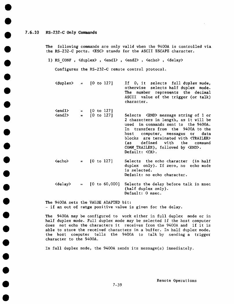
7.6.10 RS-232-C Only Commands
The following commands are only valid when the 9400A is controlled viathe RS-232-C ports. <ESC> stands for the ASCII ESCAPE character.
I) RS CONF , <duplex> , <endl> , <end2> , <echo> , <delay>
Configures the RS-232-C remote control protocol.
<duplex> = [0 to 127] If 0, it selects full duplex mode,otherwise selects half duplex mode.The number represents the decimalASCII value of the trigger (or talk)character.
<endl> = [0 to 127]<end2> = [0 to 127] Selects <END> message string of 1 or
2 characters in length, as it will beused in commands sent to the 9400A.In transfers from the 9400A to thehost computer, messages or datablocks are terminated with <TRAILER>(as defined with the commandCOMM TRAILER), followed by <END>.Default: <CR>.
<echo> = [0 to 127] Selects the echo characterduplex only). If zero, nois selected.Default: no echo character.
(in halfecho mode
<delay> [0 to 60,000] Selects the delay before talk in msec(half duplex only).Default: 0 msec.
The 9400A sets the VALUE ADAPTED bit:- if an out of range positive value is given for the delay.
The 9400A may be configured to work either in full duplex mode or inhalf duplex mode. Full duplex mode may be selected if the host computerdoes not echo the characters it receives from the 9400A and if it isable to store the received characters in a buffer. In half duplex mode,the host computer tells the 9400A to talk by sending a triggercharacter to the 9400A.
In full duplex mode, the 9400A sends its message(s) immediately.
Remote Operations7-39

In half duplex mode, after it has received the trigger character, andthe selected delay has elapsed the 9400A sends its messages one at atime until <END> message. It needs a trigger for each message. If thehost echoes received characters, echo mode must be selected. In thatcase, the 9400A discards any received characters (except those ofDevice Clear Command) until it receives the <echo> character.
The 9400A may be configured for Half Duplex mode in two situations:
a) If the computer which controls the 9400A through the RS-232-C Remoteport, does not support full duplex communication and cannot supportdata flow between the 9400A and itself in both directionssimultaneously (e.g. if the port on the computer can only be open inone direction at a time).
b) If the computer, which controls the 9400A, echoes characters itreceives from the 9400A (the port acting as a terminal port).
In the first case, the 9400A can be configured with the followingsequence of commands:
<ESC>
COMM TRAILER OFFRS CONF 9,13,10,0,0
disables echoing of characters received by the9400A.disables trailer.selects half duplex mode with <TAB> (decimal9)as a talk character, <CR> <LF> (decimal 13 andi0) as <END> message string, no echo characterand no turnaround delay.
Whenever the computer interrogates the 9400A to get one or severalresponses, or to get one more blocks of data, it sends the commandfollowed by <CR> (optional) and <LF> and then by <TAB>. <TAB> puts the9400A into the talker mode and instructs the 94OOA to send one responseor one block of data to the computer. To get more information or moreblocks, <TAB> must be re-sent.
Example:
The computer wants to know time base and bandwidth limit settings.
Computer sends:9400A answers:Computer sends:9400A answers:
TIME/DIV ?; BANDWIDTH ?<CR><LF><TAB>TIME/DIV 2.00E-O3<CR><LF><TAB>BANDWIDTH ON<CR><LF>
The characters which put the 9400A into a talker mode and thecharacters of the <END> message string must not be the same. If theywere, <END> would purge the second part of the output.
7-40Remote Operations
If turnaround delay is necessary, i.e. if a certain amount of time isnecessary between the time the 9400A receives the trigger character andthe time it sends the first character, the last parameter of theRS CONF must be non-zero.
Example: RS CONF 9,13,10,0,I000 with a turnaround delay of 1 second.
The turnaround delay is given in msec, therefore the value of I000corresponds to 1 sec. Note that during this delay the 94OOA may appearas dead.
In the second case, i.e. when the controller echoes characters, the9400A can be configured with the following sequence of commands:
<ESC>
COMM TRAILER OFFRS CONF 9,13,10,10,0
disables echoing of characters received by the9400A.disables trailer.selects half duplex mode with <TAB> (decimal9)as trigger (or talk) character, <CR> <LF>(decimal 13 and I0) as <END> message string,<LF> as echo character and no turnarounddelay.
Whenever the controller interrogates the 9400A to get one or severalresponses or to get one or more blocks of data, it sends the commandfollowed by <CR> (optional) and <LF> and then by <TAB>. This lastcharacter instructs the 9400A to send one response or one block ofdata. To get more information or more blocks <TAB> must be re-sent.
Example:
The computer wants to get the setup configuration. If the 9400A hasbeen configured to sends blocks of data in hex format in blocks of 300characters, the computer will receive 3 blocks.
Computer sends: SU ?<CR><LF><TAB>9400A answers: #L ....... <CR><LF>
Each character including <LF> will be echoed by the computer.Computer sends: <TAB>9400A answers: #L ....... <CR><LF>
Each character including <LF> will be echoed by the computer.Computer sends: <TAB>
9400A answers: #1<CR><LF>#1<CR><LF> will be echoed by the computer.
Notice that <LF> is used both as the last character of <END> messagestring and as the <ECHO> character. Character strings (except <ESC> string for DEVICE CLEAR and <ESC>, <ESC>, <ESC>, <ESC>) will be lost ifsent between <TAB> and <LF>.
In both cases, if a service request has been activated, the string willbe sent only when the trigger character is received.
7-41Remote Operations

In both cases, DEVICE CLEAR ( <ESC>C ) resets the RS-232-C remote portto the DEFAULT setting, i.e.:
- ECHO ON- full duplex mode with <CR> as <END> message string.- Overwrite mode if the output buffer becomes full.
2) RS SRQ , [0 to 127] , [0 to 127] , [0 to 127]
Defines a 3-character service request (SRO) string that is sent the 9400A each time the RQS bit (bit 6) of the Main Status Byte(STB I) is set to i. A null character (value O) terminates string, i.e. a string of 1 or 2 characters may be defined by settingthe rest of the characters to O. If the first character is set tonull (value 0), the default string is selected. Default is the bell(value 7). If half duplex mode is selected, the transmission of thisstring may be delayed until the trigger character has been received.The 9400A appends <END> to the SR0-string, but not the <TRAILER>.
3) <ESC>
Selects DTR / CTS hardwire handshake protocol.
THIS COMMMAND IS IMMEDIATELY EXECUTED.
4) <ESC>
Selects XON (ASCII DCI character) / XOFF (ASCII DC3 character)handshake protocol. (DEFAULT)
THIS COMMAND IS IMMEDIATELY EXECUTED.
5) <ESC>[
The 9400A does not echo characters received.
THIS COMMMAND IS IMMEDIATELY EXECUTED.
6) <ESC>]
The 9400A echoes characters received. (DEFAULT).
THIS COMMMAND IS IMMEDIATELY EXECUTED.
7) <ESC>
When its output buffer is full, the 9400A stops until more space iscreated in the output buffer (i.e. until the host computer has readsome characters).
THIS COMMMAND IS IMMEDIATELY EXECUTED.
7-42Remote Operations

8) <ESC>
If the output buffer becomes full, the 9400A overwrites the lastcharacter. (DEFAULT).
THIS COMMMAND IS IMMEDIATELY EXECUTED.
9) <ESC>
Sets the 9400A to REMOTE.
I0) <ESC>
Sets the 9400A to LOCAL.
II) <ESC>
The 9400A executes a DEVICE CLEAR command, clears the input andoutput buffers, all the status bytes except STB 4, and all thecorresponding masks. It then terminates plotting and datatransmission and resets the RS-232-C REMOTE port to DEFAULTsetting.
THIS COMMMAND IS IMMEDIATELY EXECUTED.
12) <ESC>
The 9400A executes a TRIGGER command (see Section 7.6.9).
7.7 Binary Format of Waveform Descriptors
The waveform descriptor contains all information needed to correctlyinterpret the waveform data. In addition, there are some values thatapply only to some records, in particular to waveforms that are theresult of data processing.
The descriptor contains 8-bit values, 16-bit values and 32-bit integervalues. There are no floating point values. Multi-byte values arealways transferred with the most significant byte first. In thefollowing list, each parameter is identified by its (decimal) addressrelative to the beginning of the descriptor, and by the number of bits.Data values shown are always in decimal.
Note: The first 4 bytes are header information in agreement withIEEE-488 specifications. The 5th byte is POS O.
Remote Operations7-43

Pos Size Meaning
2
4
6
7
8
9
8-bit
8-bit
16-bit
16-bit
8-bit
8-bit
8-bit
8-bit
Fixed vertical gain, coded as an integer.22 = 5 mV/div 23 = i0 mV/div24 = 20 mV/div 25 = 50 mV/div
....... 31 = 5 V/div
Values below 22 and above 31 may occur on processed datarecords. See Section 7.10.1 for an example of how datavalues are converted to volts in processed data records.
Variable vertical gain, in units of 0.005 of unity.0 = gain of 0.4, 120 = gain of 1.000.See Section 7.10.1 for an example of how data values areconverted to volts in processed data records.Unused
Vertical offset in units of 0.04 of the verticaldeflection factor, i.e. 0.04 V/div.
0 = - 8 div 25 = - 7 div50 = - 6 div .....
200 = 0 div 225 = 1 div250 = 2 div .....400 = 8 divSee Section 7.10.i for an example of how data values areconverted to volts in processed data records.
Input channel coupling at acquisition.0 = DC, 50 Q 1 = Ground2 = DC, 1M~ 3 = Ground4 = AC, 1M@
Attenuation of external probe (must have been set upmanually or by remote control)0 = *i 1 = *i02 = *100 3 = *1000This value is already absorbed into the fixed verticalgain (position 0), it serves only as a reminder here.
Bandwidth limit at acquisition.0 = off 1 = on
Time base at acquisition, coded as an integer.4 = 2 nsecldiv 5 = 5 nsec/div6 = 10 nsecldiv 7 = 20 nsec/div
..... 34 = 20 sec/div35 = 50 sec/div 36 = 100 sec/div
7-44Remote Operations

8) <ESC>
If the output buffer becomes full, the 9400A overwritescharacter. (DEFAULT).
THIS COMMMAND IS IMMEDIATELY EXECUTED.
9) <ESC>
Sets the 9400A to REMOTE.
the last
I0) <ESC>
Sets the 9400A to LOCAL.
11) <ESC>
The 9400A executes a DEVICE CLEAR command, clears the input andoutput buffers, all the status bytes except STB 4, and all thecorresponding masks. It then terminates plotting and datatransmission and resets the RS-232-C REMOTE port to DEFAULTsetting.
THIS COMMMAND IS IMMEDIATELY EXECUTED.
12) <ESC>
The 9400A executes a TRIGGER command (see Section 7.6.9).
7.7 Binary Format of Waveform Descriptors
The waveform descriptor contains all information needed to correctlyinterpret the waveform data. In addition, there are some values thatapply only to some records, in particular to waveforms that are theresult of data processing.
The descriptor contains 8-bit values, 16-bit values and 32-bit integervalues. There are no floating point values. Multi-byte values arealways transferred with the most significant byte first. In thefollowing list, each parameter is identified by its (decimal) addressrelative to the beginning of the descriptor, and by the number of bits.Data values shown are always in decimal.
Note: The first 4 bytes are header information in agreement withIEEE-488 specifications. The 5th byte is POS 0.
Remote Operations7-43
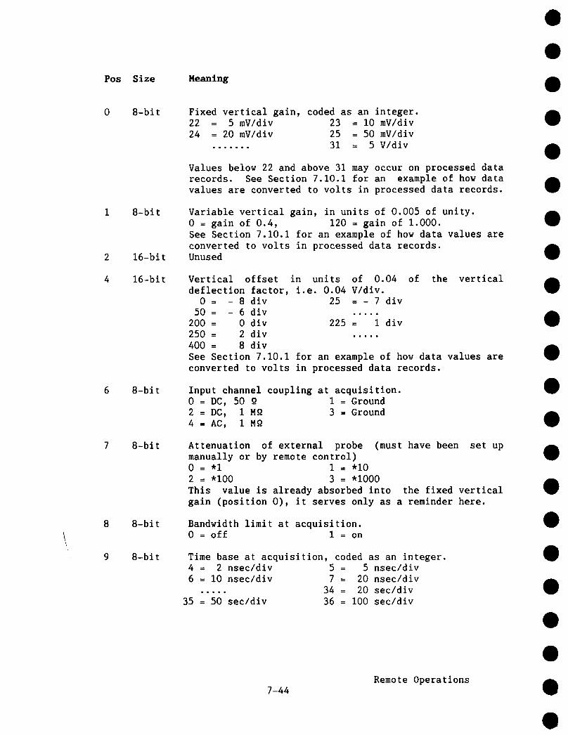
Pos Size Heaning
8-bit
8-bit
16-bit
16-bit
8-bit
8-bit
8-bit
8-bit
Fixed vertical gain, coded as an integer.22 = 5 mV/div 23 = i0 mV/div24 = 20 mV/div 25 = 50 mV/div
....... 31 = 5 V/div
Values below 22 and above 31 may occur on processed datarecords. See Section 7.10.1 for an example of how datavalues are converted to volts in processed data records.
Variable vertical gain, in units of 0.005 of unity.0 = gain of 0.4, 120 = gain of 1.000.See Section 7.10.1 for an example of how data values areconverted to volts in processed data records.Unused
Vertical offset in units of 0.04 of the verticaldeflection factor, i.e. 0.04 V/div.
0 = - 8 div 25 = - 7 div50 = - 6 div .....
200 = 0 div 225 = i div250 = 2 div .....400 = 8 divSee Section 7.10.1 for an example of how data values areconverted to volts in processed data records.
Input channel coupling at acquisition.0 = DC, 50 ~ 1 = Ground2 = DC, 1M~ 3 = Ground4 = AC, 1M~
Attenuation of external probe (must have been set upmanually or by remote control)0 = *I I = *i02 = *I00 3 = *i000This value is already absorbed into the fixed verticalgain (position 0), it serves only as a reminder here.
Bandwidth limit at acquisition.0 = off i = on
Time base at acquisition, coded as an integer.4 = 2 nsec/div 5 = 5 nsecldiv6 = I0 nsec/div 7 = 20 nsec/div
..... 34 = 20 sec/div35 = 50 sec/div 36 = I00 sec/div
7-44Remote Operations
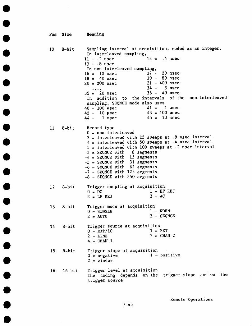
Pos Size Heaning
10
11
12
13
14
15
16
8-bit
8-bit
8-bit
8-bit
8-bit
8-bit
16-bit
Sampling interval at acquisition, coded as an integer.In interleaved sampling,
ii = .2 nsec 12 = .4 nsec13 = .8 nsec
In non-interleaved sampling,16 = lO nsec 17 = 20 nsec18 = 40 nsec 19 = 80 nsec20 = 200 nsec 21 = 400 nsec
.... 34 = 8 msec35 = 20 msec 36 = 40 msec
In addition to the intervals of the non-interleavedsampling, SEQNCE mode also uses
40 = i00 nsec 41 = 1 ~sec42 = 10 psec 43 = i00 psec
44 = I msec 45 = 10 msec
Record type0 = non-interleaved3 = interleaved with 25 sweeps at .8 nsec interval4 = interleaved with 50 sweeps at .4 nsec interval5 = interleaved with i00 sweeps at .2 nsec interval
-3 = SEQNCE with 8 segments-4 = SEQNCE with 15 segments-5 = SEQNCE with 31 segments
-6 = SEQNCE with 62 segments
-7 = SEQNCE with 125 segments
-8 = SEQNCE with 250 segments
Trigger coupling at acquisition0 = DC 1 = HF REJ2 = LF REJ 3 = AC
Trigger mode at acquisition0 = SINGLE 1 = NORM
2 = AUTO 3 = SEQNCE
Trigger source at acquisition0 = EXT/10 I = EXT2 = LINE 3 = CHAN 24 = CHAN I
Trigger slope at acquisition0 = negative I = positive2 = window
Trigger level at acquisitionThe coding depends on thetrigger source.
trigger slope and on the
7-45Remote Operations

Pos Size Meaning
18
22
24
26
28
32-bit
16-bit
16-bit
16-bit
16-bit
Positive or negative trigger slope
Parameter0
2550
I00125150200250
CHAN 1,2- 5.00 dlv- 4.00 dlv- 3.00 dlv- 1.00 div
0 dlv+ 1.00 div+ 3.00 div+ 5.00 div
EXT- 2.00 V- 1.60 V- 1.20 V- .40 V
0 V+ .40 V+ 1.20 V+ 2.00 V
In EXT/IO, the trigger voltages are multiplied by I0.
Window trigger
Parameter<252550
i00125150200250
CHAN 1 2± .50 dlv+ .50 dlv+ 1.00 dlv± 2.00 div± 2.50 dlv± 3.00 dlv± 4.00 dlv± 5.00 div
EXT± .20 V± .20 V± .40 V± .80 Vi 1.00 V± 1.20 V± 1.60 V± 2.00 V
In EXT/10, the trigger voltages are multiplied by I0.Note that the window size is limited to ±.5 div (or .20 V), due to the nature of the trigger hardware.Trigger delay at acquisition, in units of .02 ofTIME/DIV, relative to the left hand side of the screen.
500 = + I0 div, i.e. I00 % pre-trigger0 = 0 div, i.e. 0 % pre-trigger
-50 = - 1 div, i.e. post-trigger of 1TIME/DIV-500000 = -I0000 div, i.e. maximum post-trigger of I0000
divisions
Number of measured data points per division, at the timeof acquisition. This number is independent of whetherthe user reads all or a fraction of the data values, byspecifying <intval> larger than 1 (See READ command).
Address of first measured data point, relative to theleft-hand edge of the screen.
Address of last measured data point, relative to theleft-hand edge of the screen.
Internal use.
7-46Remote Operations
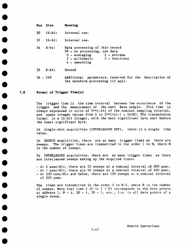
Pos Size
30 16-bit
32 16-bit
34 8-bit
35 8-bit
36 - 149
Heaning
Internal use.
Internal use.
Data processing of this record99 = no processing, raw data
0 = averaging i = extrema2 = arithmetic 3 = functions4 = smoothing
Unused
Additional parameters, reserved for thethe waveform processing (if any).
description of
7.8 Format of Trigger Time(s)
The trigger time is the time interval between the occurrence of thetrigger and the measurement of the next data sample. This time isalways expressed in units of 2,*(-14) of the nominal sampling interval,and spans integer values from 0 to 2"*(14)-1 = 16383. The transmissionformat is a 16-bit integer, with the most significant byte sent beforethe least significant byte.
In single-shot acquisition (INTERLEAVED OFF), there is a single timevalue.
In SEQNCE acquisition, there are as many trigger times as there aresweeps. The trigger times are transmitted in the order i to N, where Nis the number of sweeps.
In INTERLEAVED acquisition, there are as many trigger times as thereare interleaved sweeps making up the acquired trace:
- At 2 ~sec/div, there are 25 sweeps at a nominal interval of 800 psec.- At I ~sec/div, there are 50 sweeps at a nominal interval of 400 psec.- At 500 nsec/div and below, there are i00 sweeps at a nominal interval
of 200 psec.
The times are transmitted in the order 0 to N-I, where N is the numberof sweeps. Note that time i (0 <= i < N) corresponds to the data pointsat address i, N + i, 2N + i, 3N + i, etc., i.e. to all data points of asingle sweep.
7-47Remote Operations

In many data analyses, the trigger times may be ignored, especially ifrelative time measurements are made. In INTERLEAVED acquisition,however, ignoring the trigger times results in the interleaved sweepsbeing put on an equidistant timing grid, although they are notnecessarily equidistant at acquisition. This is equivalent tointroducing an acquisition jitter of up to 0.~ nominal samplinginterval, i.e. degrading the (apparent) dynamic behavior of the ADC.
7.9 Data Addressing Conventions
Data values are always addressed in a screen-oriented manner. Address 0always corresponds to the data value at the left hand edge of thedisplay screen. Although the 9400A always digitizes 32000 points(except in interleaved sampling or in SEQNCE mode), it is not possibleto display all of them on the screen, because of the ratio TIME/DIV tosampling interval. Points which are inaccessible on the screen arealways positioned to the LEFT of the display screen, and can be read byremote control (using negative address values).
Examples:
(a) At 0.5 msec/div, a sampling interval of 200 nsec is used, whichcovers a total time of 32000 * 200 nsec = 6.4 msec. However, only10 * 0.5 msec = 5 msec can be shown on the screen. Thus, only25000 out of 32000 acquired points are shown. The other 7000points cannot be displayed on the screen, but are accessible byremote control with the READ command (using negative addresses).
.5 ms/div
left edgeof screen
I I I-7000 0 250OO
displayed record, 2500Opts, 5ms
digitized record, 3200Opts, 6.4 ms
(b) At 5 ~sec/div, a sampling interval of i0 nsec is used, covering atotal time of 32000 * 10 nsec = 320 usec. However, only10 * 5 usec = 50 usec can be shown on the screen at this time-basesetting. Only 5000 out of 32000 acquired points are shown. Theother 27000 values are not displayed, but are accessible by remotecontrol.
7-48Remote Operations

-27000
left edgeof screen
P I0 SO00
displayed record500Opts, 50 .us
digitized record, 32000pts, 320)JS
It is important to realize that at the fastest sampling rate of I0 nsecper point, a record always covers a time interval of 320 ~sec,regardless of the time base (which can range from 50 nsec/div to20 psec/div). However, the trigger point is always interpreted relativeto the left hand edge of the screen, i.e. relative to the address point0 of the record.
Example:
Compare a time base of 20 usec/div to a time base of I ~sec/div,both with a pre-trigger of i0 percent, i.e. 1 division to theright of the left edge of the screen.
20 p s/div
-12000 left edgeof screen
trigger point
displayed record, 20000 pts, 200 .us
digitized record, 32000pts, 320 ~s
2000C
-31000
311ps
JO~trigger
left edge ~/pomtof screen
1000
displayed record,1000 pts, I0 ps
digitized record, 32000 pts,320 /Js
7-49Remote Operations
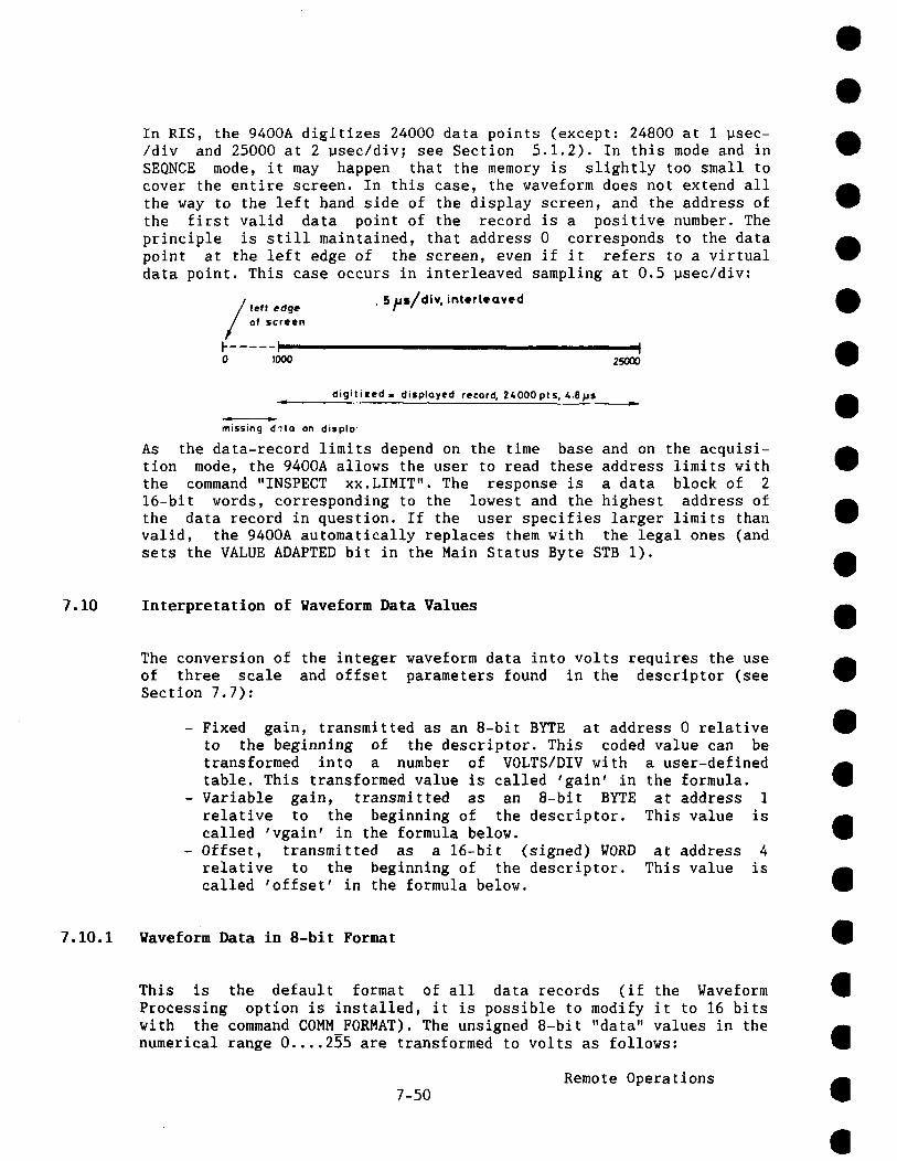
In RIS, the 9400A digitizes 24000 data points (except: 24800 at I ~sec-/div and 25000 at 2 Bsec/div; see Section 5.1.2). In this mode and inSEQNCE mode, it may happen that the memory is slightly too small tocover the entire screen. In this case, the waveform does not extend allthe way to the left hand side of the display screen, and the address ofthe first valid data point of the record is a positive number. Theprinciple is still maintained, that address 0 corresponds to the datapoint at the left edge of the screen, even if it refers to a virtualdata point. This case occurs in interleaved sampling at 0.5 usec/div:
left edge . 5~$/di~ interleaved
of screen
0 ~000 25O00
digltizeda displayed record, 24000pts, 4.8psm
~ssing dqta on displo
As the data-record limits depend on the time base and on the acquisi-tion mode, the 9400A allows the user to read these address limits withthe command "INSPECT xx. LIHIT". The response is a data block of 216-bit words, corresponding to the lowest and the highest address o£the data record in question. If the user specifies larger limits thanvalid, the 9400A automatically replaces them with the legal ones (andsets the VALUE ADAPTED bit in the Main Status Byte STB 1).
7.10 Interpretation of Waveform Data Values
The conversion of the integer waveform data into volts requires the useof three scale and offset parameters found in the descriptor (seeSection 7.7):
- Fixed gain, transmitted as an 8-bit BYTE at address 0 relativeto the beginning of the descriptor. This coded value can betransformed into a number of VOLTS/DIV with a user-definedtable. This transformed value is called ’gain’ in the formula.
- Variable gain, transmitted as an 8-bit BYTE at address 1relative to the beginning of the descriptor. This value iscalled ’vgain’ in the formula below.
- Offset, transmitted as a 16-bit (signed) WORD at address relative to the beginning of the descriptor. This value iscalled ’offset’ in the formula below.
7.10.1 Waveform Data in 8-bit Format
This is the default format of all data records (if the WaveformProcessing option is installed, it is possible to modify it to 16 bitswith the command COMM FORMAT). The unsigned 8-bit "data" values in thenumerical range 0 .... 255 are transformed to volts as follows:
7-50Remote Operations

Idata-128 °fret 2°oil20° 1V = gain32 25 vgain + 80
- The first expression "(data - 128)/32" transforms the unsigned datavalue to a signed value, in units of vertical divisions.
- The second expression "(offset - 200)/25" translates the internalcoding of the offset into a signed offset, units: vertical divisions.
- The third expression "200/(vgain + 80)" takes into account thevariable gain. It reduces, to the value 1 when "vgain" assumes the"calibrated" value of 120.
Examples:
gain = I00 mV byt e 0 of descriptor = 26offset = 200 no offsetvgain = 120 calibrated gain
The formula reduces to
V = I00 mV (data - 128)/32
data volts
0 -400 mV128 0 mV129 3.12 mV160 +I00 mV240 +350 mV255 +396.88 mV
gain = 500 mV byte 0 of descriptor = 28offset = 250 offset = + 2 divvgain = 20 variable gain = .500 (equivalent to
MULTIPLYING thevertical scale by 2)
The formula reduces to
V = 500 mV ((data - 128)/32 - 2) *
data volts
0 -6.0 V64 -4.0 V
128 -2.0 V192 0 V193 31.25 mV200 .25 V240 I. 5 V255 i. 969 V
7-51Remote Operations

7.10.2 Waveform Data in 16-bit Format
This format is only possible if the Waveform Processing option isinstalled. The 9400A must be set to this format with the commandCOMM FORMAT. In this format, raw data, i.e. 8-bit ADC output, arerepresented in the most significant byte. The least significant byteconsists of 8 bits of zeros. The unsigned 16-bit data values in therange 0 - 65535 are transformed into volts as follows:
V = gain * ((data - 32768)/8192 - (offset - 200)/25) * 200/(vgain
The terms are identical to those of Section 7.10.1, except that thefactors of the first expression are multiplied by 256.
7.11 Use of the Service Request (SRQ) Interrupts
A Service Request (SRQ) is generated whenever the RQS bit of the MainStatus Byte (STB i) becomes 1. The user must demask the condition bitsof interest in order to allow the generation of SRQ, e.g., to make the9400A generate an interrupt upon the occurrence of an overload ineither channel I or 2:
MASK 4,6 Sets the mask of the INTERNAL STATE byte (STB 4) to thebinary value 00000110, i.e. it demasks the 2 overload bits.If an overload occurs, the mask now allows the propagation ofthe bit to the INTERNAL STATE CHANGE bit of the Main StatusByte (STB I).
MASK 1,8 Sets the mask of the Main Status Byte (STB I) to the binaryvalue 00001000, i.e. it demasks the bit INTERNAL STATECHANGE. This now allows the propagation of this bit to theRQS bit of STB i. Note that the R0S bit need not be demasked;it always generates an SRQ when set.
7.11.1 Service Request in GPIB
The Service Request (SRQ) is a dedicated interrupt line on the GPIBbus. The handling of this interrupt is the responsibility of the user’sGPIB driver on the host computer. The driver may allow the linking of auser-written service routine to the interrupt. The GPIB protocol allowsan alternative way of reading the Main Status Byte (STB I) through theSerial Poll. The execution of the serial poll is again a GPIB driverroutine on the host computer. Normally, the value of STBI is identical,whether it is read by Serial Poll or with the explicit read command"STB i,?". A difference occurs, however, when more than one conditionoccurs that may set the RqS-bit:
Remote Operations7-52
- The Main Status Byte (STB i), as read with "STB i,?", keepsaccumulating further bits as they get set.
- The Main Status Byte (STB I), as read with the Serial Poll, onlyshows the bits that were set at the time the RQS was set. Any bitsthat should get set due to subsequent events are not taken intoaccount (but are remembered), until a Serial Poll reads STB 1 andclears it; at this point in time, any remembered bit is set in STB 1and may again generate an SRQ. The principle in Serial Poll is thatSRQ may be generated by one event at a time.
Example:
MASK 1,48 Sets the mask of the Main Status Byte (STB i) to thebinary value 00110000, allowing the ERROR bit or theOPERATION COMPLETE bit to generate an RQS bit, i.e. togenerate a Service Request.
MASK 5,4 Sets the mask of the OPERATION COMPLETE byte (STB 5) the binary value 00000100, allowing the propagation of the"calibration done" bit to the OPERATION COMPLETE bit ofSTB i.
MASK 6,1 Sets the mask of the ERROR byte (STB 6) to a non-zerovalue, allowing the propagation of errors to the ERROR bitof STB i.
CAL Instructs the 9400A to calibrate itself. Afterapproximately 500 msec, the 9400A sets the "calibrationdone" bit in the OPERATION COMPLETE byte (STB 5). Sincethis bit is demasked, it is propagated to the OPERATIONCOMPLETE bit of STB I. And because this bit is alsodemasked, it sets the RQS bit and generates a ServiceRequest interrupt on the GPIB bus.
TRIG LEVEL Instead of responding to the Service Request, the hostcomputer sends this illegal command. It generates asemantic error and sets the ERROR byte (STB 6) to thevalue 40. Since this byte is demasked, the ERROR bit inSTB 1 is also set, and because this bit is also demasked,it may set the RQS bit. However, the RQS bit is alreadyset.
At this point, the host computer may choose to respond to the ServiceRequest in either of the following ways:
7-53Remote Operations

If it responds with a Serial Poll, it will read the binary value01010000, i.e. the R0S bit and the OPERATION COMPLETE bit. Uponexecution of the Serial Poll, these two bits are reset in STB I.However, the 9400A remembers that another bit, capable of setting ROS,was set, in this case the ERROR bit. Thus, it generates a secondService Request. When the host computer executes a second Serial Poll,it will read the binary value 01100000, i.e. the ROS bit and the ERRORbit. Upon execution of the second Serial Poll, STB 1 will be clearedcompletely. Thus, 2 different bits of STB I (when demasked) alwaysgenerate two different Service Requests, provided that STB 1 is read bySerial Poll. This follows the principle that SRQ should be generated byone event (at the level of STB I) at a time.
If the host computer responds by reading the status byte(s) with "STB1,?" or "STB ?", it will read the binary value 01110000 in STB I. TheMain Status Byte (STB I) is cleared, and no more Service Requests aregenerated. Thus, STB I, when read explicitly, keeps accumulating otherstatus bits, and there might be fewer Service Requests than events (atthe level of STB I).
Another Example:
MASK 1932 Sets the mask of the Main Status Byte (STB i) to thebinary value 00100000, allowing the ERROR bit to generatean R0S bit, i.e. to generate a service request.
MASK 6,1 Sets the mask of the ERROR byte (STB 6) to a non-zerovalue, allowing the propagation of errors to the ERROR bitof STB I.
TIME/DIV? This legal command generates a response message which can(and should) be read by the host computer. In addition,the MESSAGE READY bit is set in STB i. Because this bit isnot demasked it does not generate an SRQ. However, if STB1 is now read explicitly or by Serial Poll, the binaryvalue I0000000 (= 80 in hexadecimal) would be read.
AAA? This illegal command generates a syntax error and sets theERROR byte (STB 6) to the value II. Simultaneously, theERROR bit of STB I is set. Since this bit is demasked inSTB I, it sets the R0S bit and generates a service requestSR0.
CALL HOST This command is illegal, since the required parameter ismissing. It generates a semantic error and sets the ERRORbyte (STB 6) to the value 40. This error should again propagated to the ERROR bit of STB l, but it cannotgenerate a service request, since it is still pending.
7-54Remote Operations
If the host computer executes a Serial Poll at this moment, the binaryvalue Iii00000 (= E0 in hexadecimal) is read, i.e. the MESSAGE READYbit from the previous command "TIME/DIV?" and the ERROR bit + RQS bitfrom the command "AAA?" are set. Upon the execution of the Serial Poll,these bits are reset. Since no DIFFERENT bit, capable of setting RQS,was generated in the intervening time, no more Service Requests aregenerated. If the host computer reads the ERROR byte (STB 6) with thecommand "STB 6,?", it will receive the value 40, corresponding to thesecond error. Thus, if several errors occur before the host computerresponds, only the last error is retained by the 9400A.
7.11.2 Service Request in RS-232-C
The Service Request must be simulated on a RS-232-C connection, sinceit is not predefined. On the 9400A, the RS-232-C Service Requestconsists of i to 3 characters, followed by the RS-232-C version of<END> (as defined by the command RS CONF in Section 7.6.10, default isCR), sent by the 9400A to the host -computer. It is the responsibilityof the programs on the host computer to recognize them. By default,they consist of 1 bell character (binary value 7).
Since transfers over RS-232-C can only be in ASCII, the bell characteris rather easily recognized as a special message. Also, the user mayredefine the SRQ characters to some other sequence with the command"RS SRQ". The Serial Poll does not exist on an RS-232-C connectioneither. The only way to get more information about the status of the9400A, or the reasons for an "interrupt", is to read the value of STB ior the other status bytes.
Of course, the user always has the choice of working without anyService Requests by "polling" the Main Status Byte (STB I) with thecommand "STB I,?" (See Section 7.6.8).
Example:
MASK 1,40
MASK 4,6
MASK 6,1
Sets the mask of the Main Statusbinary value 00101000, allowingINTERNAL STATE CHANGE to generategenerate a service request.
Byte (STB I) to thethe ERROR bit or thean RQS bit, i.e. to
Sets the mask of the INTERNAL STATE byte (STB 4) to thebinary value 00000110, i.e. it demasks the 2 overloadbits. If an overload occurs, the mask now allows thepropagation of the bit to the INTERNAL STATE CHANGE bit ofSTB i.
Sets the ERROR byte (STB 6) to a non-zero value, allowingthe propagation of errors to the ERROR bit of STB i.
7-55Remote Operations
TIME/DIV ? This legal command generates a response message whichshould be read by the host computer. In addition, theMESSAGE READY bit is set in STB i. Because this bit is notdemasked, it does not generate a Service Request. However,if STB I were now read with "STB I,?", the binary valueI0000000 (= 80 in hexadecimal or = 128 in decimal) wouldbe read, and this bit would be cleared.
Overload I This event, internal to the 9400A (but due to too large signal at input 1 with 50 Q coupling), sets the OVERLOAD1bit of STB 4. Since this bit is demasked, the INTERNALSTATE CHANGE bit of STB 1 is also set. And because thisbit is also demasked, the RQS bit is set and the ServiceRequest is generated. If set to the default string, itconsists of sending 1 bell character (decimal 7), followedby the carriage return character (default value of <END>),via RS-232-C to the host computer.
AAA? This illegal command generates a syntax error, and setsthe ERROR byte (STB 6) to the value ii. Since this byte demasked, the ERROR bit in STB I is also set. And becausethis bit is also demasked, it should also set the RQS bitand generate a Service Request. However, it cannot sinceit is already pending.
If the host computer reads the Main Status byte with the command "STBi,?" at this moment, it will read the binary value llll0000, coded asthe decimal value 240 = 128+64+32+16. The Main Status Byte (STB i) actsas an accumulator of all condition bits. Thus several bits are set.After reading STB i, all bits will be cleared and no more ServiceRequests are generated until some new event occurs.
7-56Remote Operations
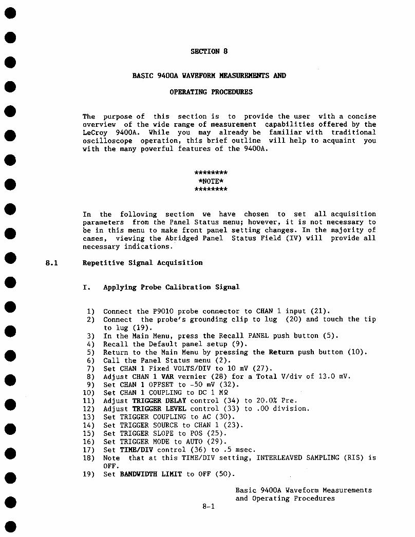
SECTION 8
BASIC 9400A WAVEFORM MEASUREMENTS AND
OPERATING PROCEDURES
The purpose of this section is to provide the user with a conciseoverview of the wide range of measurement capabilities offered by theLeCroy 9400A. While you may already be familiar with traditionaloscilloscope operation, this brief outline will help to acquaint youwith the many powerful features of the 9400A.
********
*NOTE*********
8.1
In the following section we have chosen to set all acquisitionparameters from the Panel Status menu; however, it is not necessary tobe in this menu to make front panel setting changes. In the majority ofcases, viewing the Abridged Panel Status Field (IV) will provide allnecessary indications.
Repetitive Signal Acquisition
I. Applying Probe Calibration Signal
1) Connect the P9010 probe connector to CHAN 1 input (21).2) Connect the probe’s grounding clip to lug (20) and touch the tip
to lug (19).3) In the Main Menu, press the Recall PANEL push button (5).4) Recall the Default panel setup (9).5) Return to the Main Menu by pressing the Return push button (i0).6) Call the Panel Status menu (2).7) Set CHAN 1 Fixed VOLTS/DIV to I0 mV (27).8) Adjust CHAN 1VAR vernier (28) for a Total V/div of 13.0 mV.9) Set CHAN 1 OFFSET to -50 mV (32).
i0) Set CHAN 1 COUPLING to DC 1 M9ii) Adjust TRIGGER DELAY control (34) to 20.0~ Pre.12) Adjust TRIGGER LEVEL control (33) to .00 division.13) Set TRIGGER COUPLING to AC (30).14) Set TRIGGER SOURCE to CHAN i (23).15) Set TRIGGER SLOPE to POS (25).16) Set TRIGGER MODE to AUTO (29).17) Set TIME/DIV control (36) to .5 msec.18) Note that at this TIME/DIV setting, INTERLEAVED SAMPLING (RIS)
OFF.19) Set BANDWIDTH LIMIT to OFF (50).
8-1
Basic 9400A Waveform Measurementsand Operating Procedures

20) Return to the Main Menu by pressing the Return push button (10).21) Set CMAN 1 to ON and CHAN 2 OFF (49).22) Set DUAL GRID mode to OFF (14).
Resulting Display:
PonmlSTATUS
PANEL
’III ...................................... ’ .......
.... ¯ ................... Cl~nnel 1¯ 5 .m~tO mV
Figure 8.1
The PD010 probe has a xl0 attenuation factor. Thus, the 1 V, 976 Hzoutput calibration signal is displayed with a total amplitude ofapproximately 7.7 divisions at a Total V/div setting of 130 mV. In caseof over- or under-shoot, adjust the probe compensation trimmer, locatedon the barrel of the PDOIO, for a clean square wave contour.
II. Acquisition of a 10-20 nsec Repetitive Signal
i) Connect a fast pulse generator providing an output signal having a10 to 20 nsec period to CBAN 2 input (21).
2) In the Main Menu, press the Recall PANEL push button (5).3) Recall the Default panel setup (9).4) Return to the Main Menu by pressing the Return push button (I0).5) Call the Panel Status menu (2).6) Set CHAN 2 Fixed VOLTS/DIV as appropriate (27).7) Set CHAN 2 OFFSET to .0 mV.8) Set CHAN 2 COUPLING to DC 509) Adjust CHAN 2 VAR vernier (28) as appropriate.
I0) Adjust TRIGGER DELAY control (34) to 40.0Z Pre.ii) Adjust TRIGGER LEVEL control (33) to .00 division.12) Set TRIGGER COUPLING to AC (30).
8-2
Basic 9400A Waveform Measurementsand Operating Procedures
a
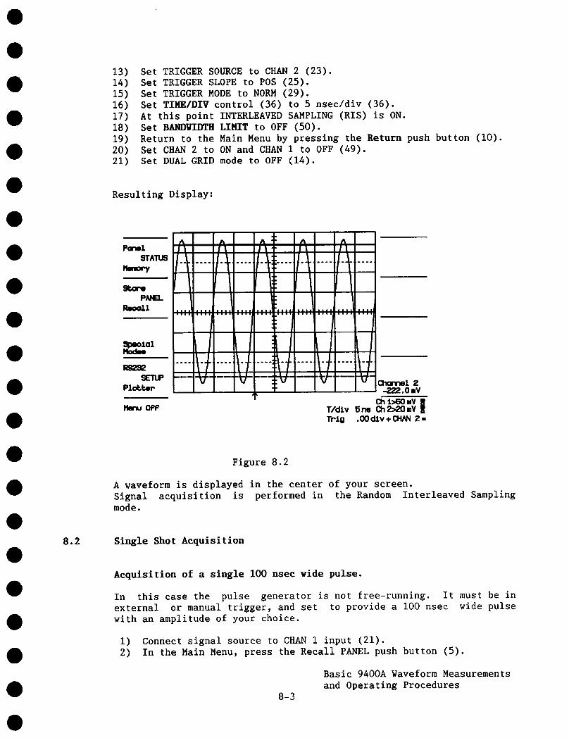
13) Set TRIGGER SOURCE to CHAN 2 (23).14) Set TRIGGER SLOPE to POS (25).15) Set TRIGGER MODE to NORM (29).16) Set TIME/DIV control (36) to 5 nsec/div (36).17) At this point INTERLEAVED SAMPLING (RIS) is ON.18) Set BANDWIDTH LIMIT to OFF (50).19) Return to the Main Menu by pressing the Return push button (I0).20) Set CHAN 2 to ON and CMAN 1 to OFF (49).21) Set DUAL GRID mode to OFF (14).
Resulting Display:
ParwlSTATUS
StorePANEL
Reo=tl
A : ~ AI% It II
r: .... ......
Trio .00 dlv+ CItAN Z ffi
Figure 8.2
A waveform is displayed in the center of your screen.Signal acquisition is performed in the Random Interleaved Samplingmode.
8.2 Single Shot Acquisition
Acquisition of a single 100 nsec wide pulse.
In this case the pulse generator is not free-running. It must be inexternal or manual trigger, and set to provide a I00 nsec wide pulsewith an amplitude of your choice.
l) Connect signal source to CHAN 1 input (21).2) In the Main Menu, press the Recall PANEL push button (5).
Basic 9400A Waveform Measurementsand Operating Procedures
8-3
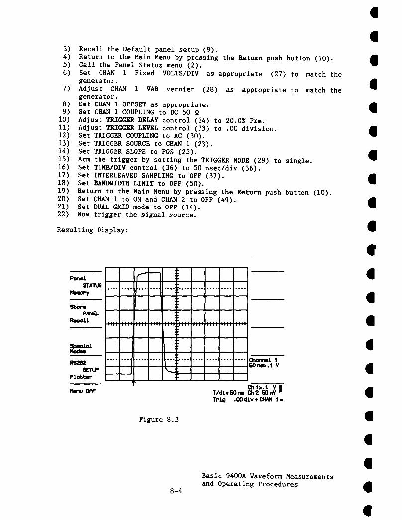
3) Recall the Default panel setup (9).4) Return to the Main Menu by pressing the Return push button (I0).5) Call the Panel Status menu (2).6) Set CHAN 1 Fixed VOLTS/DIV as appropriate (27)
generator.7) Adjust CHAN 1 VAR vernier (28) as appropriate
generator.8) Set CHAN 1 OFFSET as appropriate.9) Set CHAN 1 COUPLING to DC 50 Q
I0) Adjust TRIGGRR DELAY control (34) to 20.0~ Pre.11) Adjust TRIGGER LRVEL control (33) to .00 division.12) Set TRIGGER COUPLING to AC (30).13) Set TRIGGER SOURCE to CHAN i (23).14) Set TRIGGER SLOPE to POS (25).15) Arm the trigger by setting the TRIGGER MODE (29) to single.16) Set TIMEIDIV control (36) to 50 nsec/div (36).17) Set INTERLEAVED SAMPLING to OFF (37).18) Set BANDW-IDTff LIMIT to OFF (50).19) Return to the Main Menu by pressing the Return push button (10).20) Set CHAN 1 to ON and CHAN 2 to OFF (49).21) Set DUAL GRID mode to OFF (14).22) Now trigger the signal source.
match the
match the
Resulting Display:
...... ,......o ...o ...., ¯
!ll¯ ,,,,,.,,i.,,.,,,..i,..,i.,..i f,,. l,,,,i,,,.lq,,,,
...... Cl’mr~l ’J,50 rm~.1 V
Figure 8.3
8-4
Basic 9400A Naveform Measurementsand Operating Procedures

8.3 Trace Expansion - Expand AIB
Using the same i00 nsec signal and front panel settings described inSection 8.2, but with your pulse generator free-running this time,perform the following procedure:
I) Set push button (14) to DUAL GRID mode.2) Press EXPAND A (46) in order to expand CHAN 1 trace.
If the source for signal expansion shown in the Displayed Trace field(V) is not X-Chan I, you must perform the following procedure redefine the expansion signal source to CHAN i.
a) Press the REDEFINE push button (45) to display the RedefineSource menu in the Menu Field (I).
b) Press push button (I) in order to redefine CHAN I as the newsource for the expanded (X-Chan i) display.
At this point the new source for the expanded (X-than i) line in theDisplayed Trace Field (V) is updated to X-Chan I and all or a portionof CHAN 1 trace is intensified.
3) Turn the TIME MAGNIFIER control (43) to adjust the magnificationfactor (length of the intensified section) as desired (e.g.5 nsec).
4) Displace the intensified section by adjusting Horizontal POSITIONcontrol (39) and position it on the risetime of your pulse.
5) Position the expanded trace in lower grid by adjusting the VerticalPOSITION control (40).
6) Adjust VERT GAIN control (42) if required.
At this point the digitized points are clearly seen every 10 nsec.
7) Set INTERLEAVED SAMPLING to ON.
The equivalent sampling frequency is now 5 gigasamples/sec and therisetime of the pulse is very clearly defined.
Note: The procedure to follow for Expand B is identical to the above,except that in Step 2 the EXPAND B push button (46) is pressed ratherthan the EXPAND A push button.
8-5
Basic 9400A gaveform Measurementsand Operating Procedures

ParmlSTATUS
PANEL
,/f
15n~.t V
ChaTml 1RS2~ EO n~.l VSETUP
Plol~ter /
H~u OPP (:h t>.1 V~T/d;I.vSOrw Ch2 EOmVTr;I.o .00 d:l.v + CHAN 1 ,,
Figure 8.4
8.4 Sequential Recording of Single Events in Segmented Memory
I. 31 Segment Memory Partitioning
Using the same 100 nsec signal and front panelSection 8.2, and with your pulse generatortrigger, perform the following procedure:
settings described inin external or manual
1) Call the Panel Status menu by pressing push button (2).2) Press Modify # Segments push button (4) as often as necessary
display the value 31 in the # Segments for SEONCE line.3) Set RANDOM INTERLEAVED SAMPLING to OFF.4) Set the Time Base to .1 psec/division.5) Select SEQNCE trigger mode (29).6) Press the Return push button (10) to return to the main menu.7) Set DUAL GRID (14) to ON.8) Actuate your generator external trigger a total of 31 times in
order to generate 31 signals to be recorded.
At this point a compacted trace of 31 segments is displayed in theupper grid. Trace expansions EXPAND A and EXPAND B must be used todisplay details of one or two selected segments.
9) Press EXPAND A (46) in order to expand CHAN
8-6
Basic 9400A Waveform Measurementsand Operating Procedures
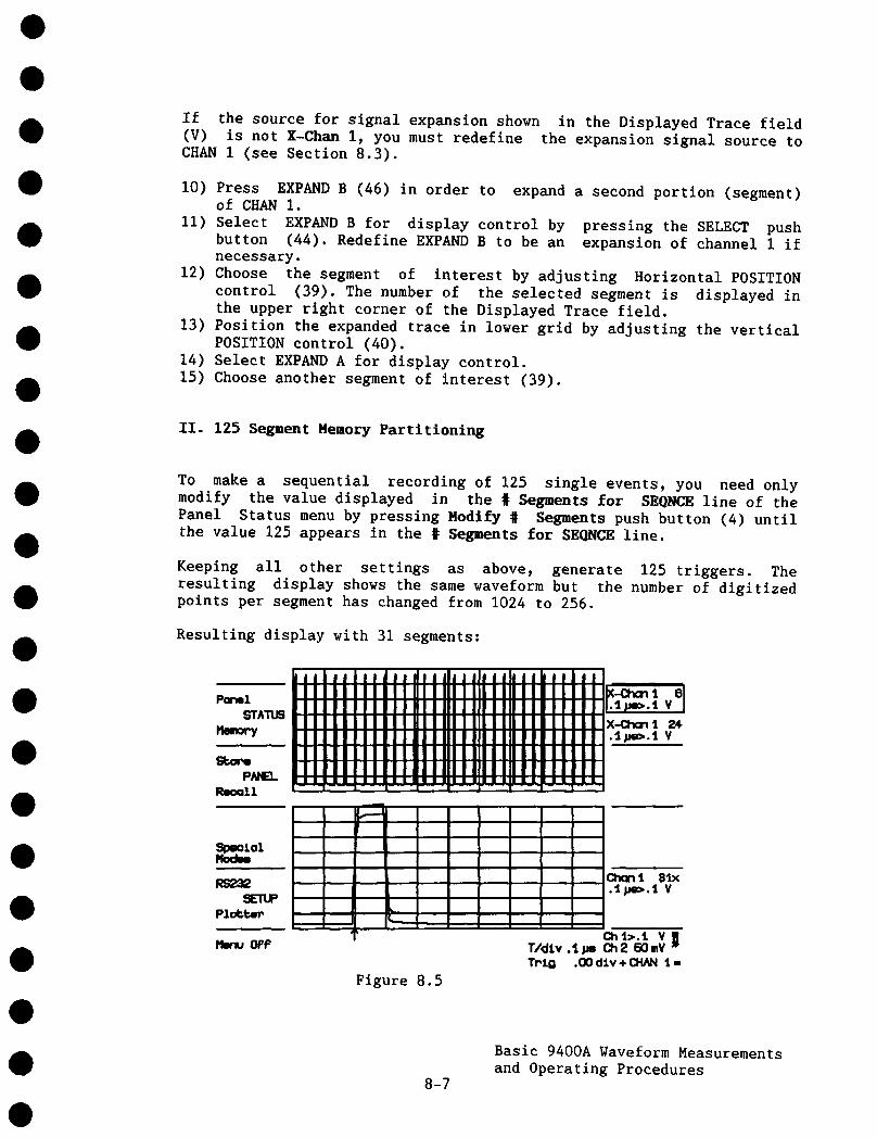
If the source for signal expansion shown in the Displayed Trace field(V) is not X-Chart I, you must redefine the expansion signal source CHAN I (see Section 8.3).
10) Press EXPAND B (46) in order to expand a second portion (segment)of CHAN I.
II) Select EXPAND B for display control by pressing the SELECT pushbutton (44). Redefine EXPAND B to be an expansion of channel 1 necessary.
12) Choose the segment of interest by adjusting Horizontal POSITIONcontrol (39). The number of the selected segment is displayed the upper right corner of the Displayed Trace field.
13) Position the expanded trace in lower grid by adjusting the verticalPOSITION control (40).
14) Select EXPAND A for display control.15) Choose another segment of interest (39).
II. 125 Segment Memory Partitioning
To make a sequential recording of 125 single events, you need onlymodify the value displayed in the # Segments for SEONCE line of thePanel Status menu by pressing Modify # Segments push button (4) untilthe value 125 appears in the # Segments for SEQNCE line.
Keeping all other settings as above, generate 125 triggers. Theresulting display shows the same waveform but the number of digitizedpoints per segment has changed from 1024 to 256.
Resulting display with 31 segments:
kJJiJJ|lJiJmdJJdJJJhJlhlJkJJiJmI I II II II I III III IIIII IIII III III I II IIPanol
STATUS
PANEL I- ~--n---r -r- -r- r----T- 1----1--
8I~.I ~e>.1 V
X-Cho~ 1 24..] ~Ji~.5 Y
RS2S2SETUP
Plc*.~."
OFP
L
Figure 8.5
Chant 91x.~.~ V
Ch 4.>.’J. V~T/dlv .t.ue Ch2 50mVTN.O .00 d:Lv + CHANt ,,
8-7
Basic 9400A Waveform Measurementsand Operating Procedures
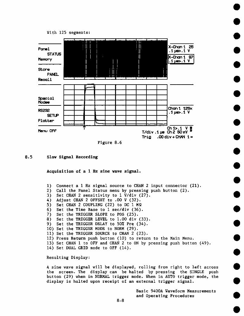
t
With 125 segments:
PanelSTATUS
MemoPy
8~oPePANEL
Re(x~11
Menu OPP
Figure 8.6
Ch 1>.1 V~T/dJ.v .1.uo Ch2 F~mVTr’J.g .00 dlv + CH/kN 1 =
8.5 Slow Signal Recording
Acquisition of a 1 Hz sine rave signal.
I) Connect a 1Hz signal source to CHAN 2 input connector (21).2) Call the Panel Status menu by pressing push button (2).3) Set CHAN 2 sensitivity to 1V/div (27).4) Adjust CHAN 2 OFFSET to .00 V (32).5) Set CHAN 2 COUPLING (22) to DC 1Mg6) Set the Time Base to 1 sec/div (36).7) Set the TRIGGER SLOPE to POS (25).8) Set the TRIGGER LEVEL to 1.00 dlv (33).9) Set the TRIGGER DELAY to 50~ Pre (34).I0) Set the TRIGGER MODE to NORM (29).II) Set the TRIGGER SOURCE to CHAN 2 (23).12) Press Return push button (i0) to return to the Main Menu.13) Set CHAN 1 to OFF and CHAN 2 to ON by pressing push button (49).14) Set DUAL GRID mode to OFF (14).
Resulting Display:
A sine wave signal will be displayed, rolling from right to left acrossthe screen. The display can be halted by pressing the SINGLE pushbutton (29) when in NORMAL trigger mode. When in AUTO trigger mode, thedisplay is halted upon receipt of an external trigger signal.
8-8
Basic 9400A Waveform Measurementsand Operating Procedures
8.6 Vindov Triggering
Window triggering allows the user to capture signals exceeding thepositive or negative limits set around the base line (in internaltrigger) or ground (in external trigger) with the TRIGGER LEVEL control(33).
Using the same basic acquisition parameters and signal used in Section8.5, it is possible to halt the rolling signal by increasing itsamplitude until it crosses the positive or negative "window" whichdefines the trigger conditions.
Procedure:
I) Set the TRIGGER SLOPE push button (25) to POS/NEG. (Both the and NBG LEDs will light up when push button (25) has been pressedthe correct number of times).
2) Set the COUPLING MODE push button (30) to the AUTO Trigger Mode.3) Adjust the CHAN 2 OFFSET control (32) in order to center the sine
wave display at mid-screen.4) Select a trigger "window" just beyond the positive or negative half
cycle of the currently displayed sine wave by adjusting the TRIGGERLEVEL control (33) to approximately ± 3.0 divisions.
Note that when Window Triggering has been selected via push button(25), a corresponding message is displayed below the bottom graticuleline on the right-hand portion of the screen in the abridged PanelStatus field. This field enables you to adjust the positive/negativetrigger window desired without having to call the Panel Status menu.
5) Gradually increase the amplitude of the output signal from yoursignal generator until the positive and negative half-cycle of thedisplayed sine wave exceeds 3.0 divisions with reference to thezero base line.
Resulting Display:
Rolling will cease when the rolling waveform reaches ± 3 divisions inamplitude.
8.7 Storing and Recalling Front Panel Setups
Storing repetitive signals.
i) Follow the same procedure as in Section 8.1 applying the probecalibrator signal.
2) Press the STORE PANEL (4) push button.
8-9
Basic 9400A Waveform Measurementsand Operating Procedures

At this point the listing of 7 possible front panel storage locationsappears in the MENU FIELD.
3) Press the push button adjacent to the storage location you haveselected (e.g. 2).
All the front panel settings are now stored.
4) Set CHAN 1 Fixed VOLTS/DIV to 20 mV (28) and TIME/DIV (36)to .2 msec.
Your display is now half the amplitude and the sweep speed 2.5 timesfaster.
5) Press the STORE PANEL push button (4).6) Press push button 3 to store the new panel settings.7) Press the RECALL PANEL (5) push button.8) Press push button 2.
At this point the first setting storedcorresponding display.
is recalled with the
Pressing push button (3) will recall the second setup.
8.8 Signal Storage in Memories C, D
I. Storage of CHAN 1 gaveform into Memory C
Apply the same signal as in Section 8.1-I, and recall the front panelsetup by pressing push buttons (5) and (2) in that order.
Procedure:
i) Stop acquisition by setting the TRIGGER MODE (29) to single.2) Press STORE push button (1) to call the Store Trace menu.3) Store CHAN i into Memory C (2).4) Set CHAN 1 to OFF by pressing push button (49).5) Set MEMORY C to ON by pressing push button (47).
II. Storage of CHAN 2 Waveform into Memory D
Apply a second signal, as in Section 8.3, from your pulse generator toCHAN 2 BNC connector (21).
Procedure:
I) Press STORE push button (I) to call the Store Trace menu.2) Store CHAN 2 into Memory D (5).
8-10
Basic 9400A Waveform Measurementsand Operating Procedures
3) Set CHAN 2 to OFF (49).4) Set MEMORY D to ON (47).5) Set DUAL GRID to ON by pressing push button (14).6) Select Memory D by pressing SELECT push button (44).7) Adjust VERT CAIN control (42) and Vertical POSITION control (40)
center the trace.
The above procedure enables two independent waveforms to besimultaneously stored and displayed. Calling the Memory Status menu (3)enables the user to review all the acquisition parameters.
Note that instead of storing the currently acquired CHAN 1 waveforminto Memory C and CHAN 2 waveform into Memory D, the Store Trace menualso allows the user to inverse this configuration, and to store theCHAN 1 waveform into Memory D and the CHAN 2 waveform into Memory C.
8.9 Redefinition Function - Expand Memories C, D
As mentioned in Section (5.2.4), the default signal sources for ExpandA and B are CHAN 1 and 2, respectively. It is possible, however, toexpand a waveform stored in reference Memories C and/or D by redefiningthese memories to be the new signal expansion source.
I. Expansion of MEMORY C with EXPAND A
Just as Expand A and B enabled the user to expand the signals containedin CHAN I and 2 (Section 8.3), the signals in reference Memories and/or D can be expanded as described below.
Procedure:
1) Store the signal into Memory C as described in Section 8.8.2) Press EXPAND A push button (46).3) Use the Vertical POSITION knob to separate the traces on the
screen.4) Set CHAN 1 to ON.5) Press SELECT push button (44) to frame the X-Chan i message.6) Press REDEFINE push button (45).7) Press push button (4) to define Memory C as the new signal source
for Expand A.
From this step on, the procedure to follow is identical to thatdescribed in Section 8.3 for CHAN i, 2 expansion (steps 3 through 6).
II. Expansion of Memory D with Expand B
The procedure used here is identical to that detailed above, exceptthat Expand B is substituted for Expand A in Step i, and Memory D isredefined as the new source for expansion (Step 4).
8-11
Basic 9400A Waveform Measurementsand Operating Procedures

It is possible while studying these reference waveforms tosimultaneously acquire signals via the CHAN 1 and CHAN 2 acquisitionmemories in real time. Note that you cannot display more than 4 traceson the 9400A’s screen at any time.
8.10 Auto-store in Memory C, D
As mentioned in Section 5.2.5, pressing the Special Modes push button(7) permits the user to automatically store the current CHAN 1 and/orCHAN 2 display into the unit’s two 32K reference memories followingacquisition of each waveform.
The Auto-store mode is particularly useful whenever the user wishes toacquire single events in the Normal trigger mode appearing at intervals> 2 sec. (As explained in Section 5.2.5, in the Normal trigger mode thetrigger circuit automatically re-arms after 2 see, causing thecurrently stored waveform to be erased from memory).
pressing the Modify Auto-store push button (2) once causes the waveformcurrently contained in the 9400A’s CHAN 1 acquisition memory to bestored automatically into Memory C. Continue pressing the ModifyAuto-store push button (2) to see all the possibilities:
CHAN i into Memory CCHAN 1 into Memory DCHAN 2 into Memory CCHAN 2 into Memory DCHAN 1 into Memory C and CHAN 2 into Memory D.
Auto-store in Memory C
Procedure:
I) Using the same signal as in measurement example 8.2, set TRIGGERMODE push button (29) to NORM rather than SINGLE (HOLD).
2) With the Main Menu displayed on the CRT, press the Special Modespush button (7).
3) Press Modify Auto-store push button (2) once in order to cause thesignal input to CHAN 1 to be automatically stored into Memory Cwith each new trigger cycle.
4) Return to the Main Menu by pressing Return push button (i0).
5) Call Memory C by pressing MEMORY C push button (47).
6) Trigger the signal source.
8-12
Basic 9400A Waveform Measurementsand Operating Procedures

Note that Memory C contains an exact copy of the most recent waveformstored in CHAN I. The display of CHAN 1 waveform disappears about2 seconds after a valid trigger is detected.
8.11 Common Expand Mode
Sections 8.3 and 8.8 describe the expansion of displayed tracesindependently, in order to provide a magnified version of a portion ofthe waveform currently in CHAN 1, CHAN 2 or those stored in referenceMemories C or D. However, in certain applications it is convenient tobe able to move the intensified region along two traces simultaneously.
Procedure:
Using the same front panel setup and the i00 nsec signal describedin Section 8.2, connect one of the outputs of your pulse generatorto the CHAN I input connector (21).
2) Connect a second output of your pulse generator to the CHAN 2input connector (21).
3) With the Main Menu displayed on the left-hand side of the CRT,press push button (7) to call the Special Modes menu.
4) Press Modify Common Expand push button (4) to set the oscilloscopeto the Common Expand mode.
5) Return to the Main Menu by pressing Return (I0).
6) Press DUAL GRID (14).
7) Press EXPAND A and EXPAND B (46).
8) Press RESET (41), to synchronize the intensified sections alongthe CHAN 1 and 2 trace.
Note that at this point two setsdisplayed on the screen. Separate CHANCHAN 1 or 2 OFFSET controls (32).
of overlapping traces will be1 and CHAN 2 by adjusting the
Separate expanded traces A and B by first selecting the X-CHAN i,push button (44), and then adjusting Vertical POSITION control (40). ensure easy display readability repeat this step, if necessary,selecting X-CHAN 2 instead of X-CHAN i, with the SELECT push button(44).
8-13
Basic 9400A Waveform Measurementsand Operating Procedures

In the Common Expand mode, only the Horizontal POSITION control (39)and the TIME MAGNIFIER control (43) act simultaneously on both theExpand A and B signal source, while the VERT GAIN control (42) and theVertical POSITION control (40) act independently on each expandedwaveform.
When input signals to the 9400A are to be observed at different pointsin time, it is possible to independently adjust the time differencebetween the two intensified regions prior to calling the Common Expandmode.
When the Common Expand mode is subsequently called by pressing pushbuttons (7) and (4) in that order, the intensified regions for the expansion sources may then be magnified by means of the TIME MAGNIFIERcontrol (43) and moved horizontally at a fixed time interval by meansof the Horizontal POSITION control (39).
The time cursors may be called by pressing push button (17) for high-precision measurement of the time interval between the two displayedregions.
Note that at any time the user may eliminate the time intervalseparating the intensified regions by pressing RESET push button (41).
8.12 Remote Control Via the RS-232-C Port
The 9400A has been designed to permit control of all of the scope’sfunctions by means of a computer/terminal. For a complete listing ofthe various commands used to program the 9400A see Section 7.6.
The following examples are given to present the 9400A’s remote controlfrom a computer. To disable the character echoing from the 9400A issuethe following command:
<ESC> [
Preliminary Hardware Setup:
1)
2)3)
4)
Set the thumbwheel switch (54) on the rear panel of the 9400A to value greater than 31.Power up the 9400A.Connect a computer through an RS-232-C cable to the Remote portconnector (56) on the rear panel of the 9400A.Call the RS-232-C menu by pressing push button (8). Then match thedata transfer speed and character formats of the computer andoscilloscope (See Section 5.2.6).
8-14
Basic 9400A Waveform Measurementsand Operating Procedures
I. Remote Operation in the Interrogation Mode
Programming Example: Terminal Display of Current Time Base Setting.
Programming Procedure:
I) Using any combination of upper or lower case charactersp enter theletters TD on your keyboard, followed by a space, comma or by theequal sign, followed by a question mark, followed by <CR> asfollows:
TD ? <CR>
Resulting Display:
Immediately upon execution of the above sequence you will see the9400A’s current time base setting displayed on your terminal, e.g.:
TIME/DIV I00 S
II. Remote Operation in the Control Mode
To modify the currently selected oscilloscope parameters, the user mustfirst set the 9400A to remote use. This is done by entering <ESC>R(i.e. the character <ESC> followed by upper case "R").
Programming Example: Set the Time Base to 2 msec.
Programming Procedure:
i) Enter TD 2MS <CR> (upper or lower case characters). Other possiblecharacter formats are:
TIME/DIV 2 MS <CR>TD 2E-3 <CR>TD .002 <CR>
(upper or lower case characters)(upper or lower case characters)(upper or lower case characters)
Resulting Display:
Observe the Abridged Panel Status field in the lower right-hand portionof the screen while the above character sequence is entered via theterminal keyboard. When (<CR> is pressed, you will see the currentlydisplayed time base setting change to 2 msec.
In order to return the 9400A to Local use, type <ESC>L (i.e. thecharacter <ESC> followed by upper case "L"), at which point you will bereturned to the 9400A’s initial menu (i.e. the menu which appears atunit power up).
8-15
Basic 9400A Waveform Measurementsand Operating Procedures

III. Example of a Typical Program
A short BASICA interactive program showing how to initializecommunication between a 9400A and an IBM PC-AT is given below:
I00 ’SAMPLE PROGRAM FOR LINKING THE LECROY 9400A DSO TO AN IBM PC-AT’105 ’VIA THE RS232C ASYNCHRONOUS COMMUNICATIONS INTERFACE’II0 ’115 ’AUTHOR : M. SCHUMACHER120 ’125 CLS: ON ERROR GOTO 575130 TRUE = I: FALSE = 0: LOOP = TRUE: EXIT = FALSE: ECHO = TRUE: STORE =FALSE135 CPRM$="Z"140 ’145 OPEN "COMI:9600,N,8,1" AS #i150 OPEN "SCRN:" FOR OUTPUT AS #2155 PRINT #2,"SAMPLE INTERACTIVE PROGRAM FOR LINKING THE LECROY 9400A DSO TO AN"160 PRINT #2,"IBM PC-AT VIA THE RS232C ASYNCHRONOUS COMMUNICATIONS INTERFACE"165 PRINT #2, "":PRINT #2, "Settings : 9600 Bd, no parity, 8 bits, 1 stop bit"170 PRINT #2, "": PRINT #2, "Commands :" : X$=STRING$(15,32)175 PRINT #2, X$"REM : Remote, LOC : Local"180 PRINT #2, X$"STORE : Store to disk, RECALL : Retrieve from disk"185 PRINT #2, X$"Any valid command described in the User’s Manual"190 PRINT #i, CHR$(27);"["195 PRINT #i, "CHLP PPO"200 PRINT #i, "CTRL OFF"205 PRINT #i, "CFMT,L,BYTE,UNSIGNED_SHORT"210 PRINT #i, "CBLS 70"215 PRINT #I, "MASK 6,1" ’Enable STB 1220 PRINT #I, "RS CONF 6,13,0,0,0" ’<ACK>,<CR>225 PRINT #I, "CPRM "+CHR$(34)+CPRM$+CHR$(34)230 ’235 WHILE LOOP240 PRINT #2,""245 LINE INPUT "Enter command (EX --> exit) : ", 250 IF LEN(C$) < 2 THEN 245255 IF C$ = "EX" THEN LOOP=FALSE: GOTO 285260 IF C$ = "REM" THEN C$ = CHR$(27)+"R"265 IF C$ = "LOC" THEN C$ = CHR$(27)+"L"270 IF C$ = "STORE" THEN GOSUB 380: GOTO 285275 IF C$ = "RECALL" THEN GOSUB 460: GOTO 285280 IF C$<>"" THEN PRINT #I,C$: GOSUB 300285 VEND290 CLOSE295 SYSTEM300 ’305 ’SUBROUTINE GET STRING FROM DS0310 ’315 ON TIMER(2) GOSUB 595: TIMER 320 CYCLE=TRUE325 WHILE CYCLE330 PRINT #1,CHR$(6);
8-16
Basic 9400A Waveform Measurementsand Operating Procedures

335340345350355
IF EOF(1) THEN 335TIMER STOPAS = INPUT$(LOC(1),#1) : C$=MID$(A$,I,LEN(A$))L=INSTR(C$,CPRM$): IF L>0 THEN L=L-I: C$=MID$(A$,I,L): CYCLE=FALSEIF ECHO THEN PRINT #2,C$;
360365 WEND370 TIMER OFF375 RETURN380 ’385 ’SUBROUTINE OPEN DISK FILE390 ’395 CLOSE #3
IF STORE THEN FOR I=l TO LEN(C$): PRINT #3, MID$(C$,I,I); : NEXT
400 LINE INPUT "Specify dir and disk file name : ",AS405 OPEN AS FOR OUTPUT AS #3410 STORE=TRUE415 LINE INPUT "Enter READ command (A --> abort) : " P420 IF C$="A" THEN 450425 IF INSTR(C$,"R")<>I THEN PRINT #2,"Wrong syntax" : GOTO 450 ELSE PRINT #3,C$:
PRINT #i,C$430 L=INSTR(C$,"."): IF L=0 THEN PRINT #3,"" ELSE PRINT #3,MID$(C$,L)435 LINE INPUT "Echo data to screen (Y/N) : ",AS440 IF A$="N" THEN ECHO=FALSE: PRINT #2,"Uploading ..." ELSE ECHO=TRUE445 GOSUB 300450 STORE=FALSE: ECHO=TRUE: CLOSE #3455 RETURN460 ’465 ’SUBROUTINE READ DISK FILE470 ’475 CLOSE #3480 LINE INPUT "Specify dir. and disk file name : ",AS485 OPEN AS FOR INPUT AS #3490 A$=CHR$(27)+"R": PRINT #1,AS495 LINE INPUT "Specify target memory (C/D) : ",B$’. IF B$<>"D" THEN B$="C"500 LINE INPUT #3,C$: PRINT #2,"Read command was :";C$505 LINE INPUT #3,C$510 A$="WT M"+B$+C$+CHR$(13): PRINT #1,AS;515 LINE INPUT "Echo data to screen (Y/N) : ",AS520 IF A$="N" THEN ECHO=FALSE: PRINT #2,"Downloading ..." ELSE ECHO=TRUE525 WHILE NOT EOF(3)530 AS=INPUTS(I,#3)535 IF ECHO THEN PRINT #2,A$;540 PRINT #1,AS;545 WEND550 CLOSE #3555 GOSUB 300560 A$=CHR$(27)+"L": PRINT #1,AS: GOSUB 300565 ECHO=TRUE570 RETURN575 ’580 ’DOS ERROR AND TIMEOUT HANDLER585 ’590 PRINT #2, "Error no. "; ERR: GOTO 235595 PRINT #2, "Timeout": TIMER OFF: GOTO 235
Basic 9400A Waveform Measurementsand Operating Procedures
8-17
8.13 Remote Control Via GPIB (Option OP02 only)
If the 9400A has been equipped with option OP02, it is also possible tocontrol the various functions of the 9400A via the General PurposeInterface Bus (GPIB).
Example: Set the Time Base to 1 msec.
This example is given to present the different steps necessary to use aGPIB bus. Note that most languages offer high-level routines thatperform these steps automatically.
In this example an IBM PC, or compatible computer equipped with a
National Instruments GPIB PC2 or PC2A GPIB adapter and NationalInstruments IBIC program (default settings are selected), is used.
Preliminary Hardware Setup:
i) Before powering up the 9400A, select GPIB operation by setting thethumbwheel address switch (54) to
2) Connect a GPIB cable to the 9400A’s rear panel GPIB connector (55)and to the GPIB connector of the PC.
Note that upon system initialization, the PC must be at address O.
3) In the Handler default configuration and with the prompt A>displayed on your PC’s CRT, enter:
IBIC <CR> (upper or lower case letters)
The following message will be displayed on your CRT:
National InstrumentsInterface Bus Interactive Control Program (IBIC Rev C.0)Copyright (C) 1984 National Instruments, Inc.All rights reserved
In the following description the commands which must be sent are inupper case letters. Answers or comments are in lower case. Eachcommand must be followed by <CR>.
8-18
Basic 9400A Waveform Measurementsand Operating Procedures
8.14
4) Enter IBFIND GPIB@ (in upper or lowerfollowing program will be executed:
IBSICStatus Message Returned
IBTMO 12Status Message Returned
IBEOT 1Status Message Returned
IBSRE iStatus Message Returned
IBCMD "? @$"Status Message Returned
IBWRT "TD IMS;TD ?"Status Message Returned
IBCMD "? D"Status Message Returned
case), at which
Meaning:
PC acts as controller
3 sec time-out
PC automatically enables <EOI> lineon final character of message
point the
Enable Remote 9400A operation
PC Talker; 9400A Listener9400A enters REMOTE
TIME/DIV set to 1 msec; readcurrent value
PC Listener; 9400A Talker
IBRD 120 PC to read < 120 characters andStatus Message Returned stop when it encounters <EOI>
At this point the following message will be displayed(with corresponding Hexadecimal ASCII codes to the left):
54 44 20 31 2E 30 30 45 T D I . 0 0 E2D 30 33 20 53 0D OA - 0 3 S
IBONLStatus Message Returned
Disconnect PC from GPIB; set9400A to Local operation
Exit IBIC program
the Plotter are all
E
Making a Plot when the Computer, the 9400A, andConnected Together on a GPIB Bus (Option OP02 only)
In this configuration, the computer controls the GPIB bus and thedevices that are on the bus, such as the 9400A and the plotter. The9400A cannot directly send plot data to the plotter even when it is inLOCAL. It is the task of the computer to organize the data transfer.The following sequence should be followed.
8-19
Basic 9400A Waveform Measurementsand Operating Procedures

I) The computer sets the 9400A into REMOTE.
2) The computer sets itself to Talker andsends the command:
"SCREEN DUMP"
the 9400A to Listener and
3) The computer organizes the transfer between the 9400A and theplotter in one of the ways described below. The choice depends onthe computer GPIB controller software.
The computer tells the 9400A to talk and the plotter to listen. Itputs itself in Standby Mode while waiting for E0I that will be setby the 9400A when the plot is finished.
or
The computer tells the 9400A to talk and the plotter to listen. Itputs itself in Listener mode while reading but NOT while storing theplot data.
or
The computer tells the 9400A to talk and sets itself to Listener. Itreads AND stores the plot data. Afterwards it sets itself to Talkerand tells the plotter to Listen and sends the stored data to theplotter.Notice that a larger amount of data has to be stored: up to50 kilobytes if all the traces are on.
4) The computer terminates the transfer by sending UNT (UNTalk) and UNL(UNListen) and setting the 9400A into LOCAL.
8.15 Configuring the Parallel Polling (Option OP02 only)
Send the following sequence of GPIB commands to the 9400A:
- listen address of the 9400A.- PPC (Parallel Poll Configure).- PPE (Parallel Poll Enable).
in binary : 0 11 0 S P3 P2 P1Where P3 to P1 represents DIO line number - 1
S = 1 if 1 must be sent while Service Request is active.= 0 otherwise.
- UNT (UNTalk) and UNL (UNLlisten) non obligatory.
8-20
Basic 9400A Waveform Measurementsand Operating Procedures

To "unconfigure" the parallel polling, sendGPIB commands to the 9400A:
- Listen address of the 9400A.- PPD (Parallel Poll Disable).
in binary : 0 1 11 S P3 P2 P1as mentioned above.
- PPU (Parallel Poll Unconfigure).- UNT or UNL non obligatory.
Other sequences of commands are also possible.
the following sequence of
8-21
Basic 9400A Waveform Measurementsand Operating Procedures


SECTION 9
GETTING THE MOST OUT OF YOUR 9400A
The 9400A is a highly accurate digital oscilloscope which achievesoptimum precision when handled properly.
The purpose of this section is to familiarize the user with operationsand functional hints that will ensure the best possible operation ofthe instrument.
9.1 Front Panel Controls
All front panel controls are fully remotely controllable and aretherefore constantly monitored by the 9400A’s internal processor.
Any action performed on the front panel is detected by the processorand the requested changes are implemented very rapidly.
During data acquisition (measurement of input signals), the internalprocessor is also busy with the data-taking controls, calculations anddisplay generation. Under certain conditions, (e.g. RIS mode or slowtime base), the response time of the front panel controls increases.When for example, the user tries to move a trace up or down on thescreen, it tends to move with a jumping motion.
Whenever slow response to the control knobs is noticed, set the triggermode to SINGLE. Acquisition is stopped, the display of the waveform isfrozen and the response time of control knobs returns to normal. Oncewaveform manipulations are done, return to NORMAL or AUTO trigger.
9.2 Accurate Amplitude Measurements
The 9400A digitizers are 8-bit analog-to-digital converters thatmeasure the amplitude of input signals by subdividing them into 256levels.
You can ensure maximum measurement accuracy by using the full dynamicrange of the converters, i.e. using input signals close to full scale.Half-scale signals are in 128 levels only, reducing measurementaccuracy by a factor of two.
To facilitate the adjustment of a full-scale ADC signal, the 9400Adisplay has been designed to represent the zero level of the ADC as thebottom line of the grid. Full scale, level 256, is represented by thetop line of the grid.
9-1Getting the Most Out of Your 9400A

r~ /~-j -\-.:--.-~ ! .... .~/ \::/ ...........! ..............! ...........
"’" .....’1 .............~"" I ........~\
~..i..t. -~..~ .....I .........k/ ’J
...... (:l~x~l 2p~.2 V
Cht>.2 V *T/dlv ZJm Ch2 t V -Trig- ~.48 dlv + CHAN t-
displaygrid500pointsresolution
Figure 9.1
To make the best use of the ADC’s dynamic range, and therefore the mostaccurate amplitude measurements, the displayed signal should completelyfill the display grid.
The fully calibrated and continuously adjustable input-signalconditioning permits you to meet this requirement easily without lossof calibration.
As an overlapping display of two full scale waveforms could becomequite confusing, the 9400A provides a dual grid option to be used inapplications where both channels are used simultaneously.
J"k I/ I
/ / I\ / I I\ / I \ I\ \ A\ /,,j \ / \ /I
~J mmm,~ o
HrIJ
FIGURE 9.2
I
Ch t>.2 V *T/d~v 2~ Ch2 t V =Trl0-1.4E dlv+CHN~ 1-
displaydualgrid2 x 250pointsresolution
9-2Getting the Most Out of Your 9400A

9.3 Accurate Time Measurements
Two deep acquisition memories, each storing 32000 points, provide theunprecedented time resolution of the 9400A.
In order to match the time base settings, a maximum of 25000 digitizedpoints are displayed on the screen with a resolution of 500 displaypoints. A compacting algorithm showing all minimum and maximum valuesensures that no information is lost in the display of a trace.
Time cursors can be positioned accurately on any one of the 500 displaypoints of a compacted trace. The corresponding measurement accuracy is1/500 or 0.2%.
digitized waveformmax
: " , :: ¯ : ¯ ¯
¯ , : : ¯: ¯
O .......... "" " .. ........... O .........." :: .. : f ........ <) ............: . .;
¯ $
digitized points
......¯ ~ displayed points
compacted
displaywithmin maxalgorithm
To improve measurement accuracy, two expansion functions, EXPAND A andEXPAND B are provided to display every digitized point trace.When the expansion factor is such that 500 measured points are to bedisplayed, every display point corresponds to a digitized point.
When the time base requires that less then 500 digitized points fillthe screen, the 9400A interpolates using straight line segments betweenthe actual points¯
In the example below, the compacted trace of a 25000 point waveform isexpanded by a factor of I00 with EXPAND A and B to provide maximum timemeasurement accuracy.Under these conditions, each expanded trace displays 250 digitizedpoints.Every other display point is interpolated and the time measurementaccuracy is 1/50000 = 0.002%.
Getting the Most Out of Your 9400A9-3

--- r’~ rt
i! :’ i
i
¯ ! n
, [ I
: : iA.
" : _"
|
!
’L
1
\ --
P’ U44.12. klk
I X.-Q"D’s I
(=1 t1~.2 !T/d.l.v t Jal ChZ ~lV |’l’V"d, li .3KPdA.v-CI4AN 1,,
9.4 Auto-callbratlon
Figure 9.3
As described in Section 2.5, the 9400A calibrates its time interpolatorrelative to the internal 100 MSz crystal-controlled clock generatorevery time the time base is modified by front panel operation or byremote control.
The vertical gain and offset of an input channel are calibrated bymeans of a very stable internal 12-blt digital-to-analog converterevery time the fixed gain control of this channel is modified.Calibration of both channels also takes place whenever the bandwidthlimit is changed.
These calibrations are necessary largely because of drifts caused bytemperature changes which could arise if the 9400A is left in the samestate for a very long time. To avoid measurement errors due topotential drifts, an internal timer of the 9400A forces a completeauto-calibration every minute during the first I0 minutes afterpower-up and every 20 minutes thereafter. This operation is transparentto the user, but is audible due to relay switching. Note thatauto-calibration does not occur in SINGLE or SEQNCE trigger mode.
In remote control, all auto-calibration can be turned off. It may beexecuted whenever requested (see the CALIBRATE command in
Section 7.6.6)
9-4Getting the Most Out of Your 9400A

SECTION I0
WP01 VAVEFORM PROCESSING OPTION
10.1 Processing Capabilities
The WP01 Waveform Processing Option includes an additional0.5 megabytes random access memory for accumulation, computation andwaveform buffers. This allows accumulation of averaged waveforms of32000 data points in 32-blt form.
All waveform processing occurs through the waveforms E and F which maybe displayed on the screen by pressing the corresponding FUNCTION E, F(48) push button. Whenever the FUNCTION E or F trace or an expansion one or both of these traces (in EXPAND A or B) is turned ON, thecorresponding waveform processing is executed. Whenever the trace (andits expansion) is turned OFF, the processing is suspended. This is trueeven for remote control. The display can be turned off by remotecontrol in order to gain speed (command SCREEN OFF, Section 7.6.3);however, even in this case the corresponding function trace must beturned ON although nothing is displayed on the screen.
FUNCTIONS E and F are waveforms that exist independently of (i.e. inaddition to) the acquisition memories of CHANNELS 1 and 2 and of thereference memories C and D. On the display, they are treated similarlyto memories C and D, i.e. the vertical display gain and the verticalposition can be modified, but not the horizontal position and the timemagnifier. Of course, they can be expanded by redefining the sourcewaveform of the traces EXPAND A or B.
Two different processing functions can be executed simultaneously.FUNCTIONs E and F may be read by remote control just like the othertraces, with the additional option of reading 16-bit data values, and,as with Channels 1 or 2, they may be stored in reference memories C orD by pressing the STORE push button (I). Waveform processing functionsoperate on one or two source waveforms which may be CHANNEL i or 2,Memory C or D. FUNCTION F may also operate on FUNCTION E. Since theresults of the processing functions can be stored in the referencememories, and since FUNCTIONS E and F may operate on these referencememories (and F may operate on E), chaining of operations is possible.
Waveform processing can take an appreciable execution time whenoperating on many data points. The user has the option of reducing theexecution time by limiting the number of data points which are used inthe computation.
WP01 Waveform Processing Optioni0-i

The 9400A then executes the waveform processing function og. the entirewaveform (as displayed on the screen) by taking every ~n p oint, Ndepending on the time base. The first point of such a reduced record isalways the data value at address 0 (i.e. the point on the left handedge of the screen). For readout and display, the data record isre-expanded to the original number of data points by linearinterpolation. By remote control the user can read either the entireexpanded record or the reduced record. In the second case, the usermust know the "skip factor", i.e. the value of <intval> in the readcommand (see section 7.6.5). This factor can be inspected on the memorystatus display screen, or by the inspect command.
10.2 Setting Up a Waveform Processing Function Manually
It is generally good practice to stop data acquisition while preparingnew conditions for waveform processing (by setting the trigger mode toSINGLE) because the response time might otherwise be slow, depending onthe current function setup. In order to prepare FUNCTION E or F for newconditions, or to inspect the current setup, the trace FUNCTION E or F(48) must be turned ON. Select this trace for display control with theSELECT (44) push button and press REDEFINE (45). A full page setup for this function appears on the screen. Return to the normal waveformdisplay by either pressing the "Return" soft key (I0) or the REDEFINE(45) push button.
The currently selected processing function and its parameters may bemodified with the soft keys. First select the field to be modified. Therectangular frame around parameter values indicates the currentlyselected field. Pressing the Previous FIELD push button (2) will causethe frame to move towards the top of the list, whereas pressing theNext FIELD push button (3) will cause the frame to move downwards.
Following field selection, the current value of the field may bemodified by pressing either the Previous or Next VALUE push button (6or 7). Since the identity of the lower fields may depend on thefunction chosen, modify the parameters from top to bottom.
The following waveform processing functions are available:
- Average: summed and continuous averaging- Extrema: "Roof" for maxima, "Floor" for minima- Arithmetic: Sum, Difference, Product and Ratio- Functions: Negation, Integral, Differentiation,
Root- Smoothing: 1-, 3-, 5-, 7- and 9-point smoothing
Square and Square
10-2WP01Waveform Processing Option

10.2.1 Summed Average
Summed averaging consists of the repeated addition, with equal weight,of recurrences of the source waveform. Whenever the maximum number ofwaveforms is reached, the averaging process stops. The averagingprocess may be interrupted by switching the trigger mode from NORM toSINGLE (29) or by turning the function trace OFF (48). Averaging continue when these actions are reversed.
The currently accumulated average may be reset either by changing anacquisition parameter, such as input gain, offset or coupling, triggercondition or time base, or by pressing the RESET push button (41) twicein quick succession (remember that FUNCTION E or F must be selected).The number of currently averaged waveforms is displayed in theDisplayed Trace Field (V in Figure 4.1) of the corresponding functionor of its expansion.
Whenever the maximum number of sweeps is reached, a larger number ofsweeps may be accumulated by simply changing the maximum number ofsweeps in the setup menu. In this case care must be taken to leave theother parameters unchanged, otherwise a new averaging calculation isstarted.
Summed averaging may be performed over CHANNEL I or 2. FUNCTION F mayalso average over FUNCTION E, therefore allowing averaging overfunctions.
Whenever a waveform containing overflow or under-flow values is to beadded to an average, unknown values will be added. The user may choosethe action to be taken:
- If "Artifact Rejection" is OFF, any overflows are set to the maximum(256) possible value of the ADC and any under-flows to the minimum(0). The waveform is then added to the average. Of course, theaverage will be incorrect at the overflow positions.
- If "Artifact Rejection" is ON, waveforms containing at least oneoverflow or under-flow are rejected from the average, i.e. not addedat all. If waveforms consistently contain overflows or under-flows,averaging cannot proceed and the number of accumulated sweeps maystay at zero indefinitely.
In order to improve the signal to noise ratio even further, the 9400Aoffers the possibility of performing "offset dithering". When turned on(i.e. when set to > 0 least significant bits of the ADC), the 9400Aadds a small "hardware" offset to each acquired waveform. This offsetis different for different waveforms, and the values are chosen suchthat their average is negligibly small. The function setup menu allowsa choice of the maximum excursion of this offset.
10-3WP01Waveform Processing Option

When set to the largest possible value of 6 LSB, the waveforms areoffset by up to ±.2 vertical divisions (remember that a verticaldivision corresponds to 32 least significant bits of the ADC). In thiscase, care must be taken that the waveform to be averaged is containedwithin 1/5 of a vertical division from the top and the bottom of thedisplay grid; otherwise overflows or under-flows might occur. Wheneverdithering is ON, the displays of CHANNELS 1 or 2 vary vertically withthe dithering offset. Their waveform descriptors take the additionaloffset into account so that waveforms, as read out by remote control,and cursor measurements are always correct.
Offset dithering is of interest when the waveform to be averaged isalready relatively "clean", i.e. contains noise variations of the orderof 1/5 of a division or less. In this case, dithering makes thesequentially acquired waveforms use slightly different portions of theADC. Thus the differential non-llnearities (that any flash ADC has) areaveraged out. It can be expected that the differential non-linearitiesare reduced by up to a factor of 4 when using 6 LSB dithering.Waveforms which have high levels of noise (>1/5 of a vertical division)do their own "dithering", making artificial offset variationsunnecessary.
10.2.2 Continuous Average
Continuous averaging (sometimes called exponential averaging) consistsof the repeated addition, with UNEQUAL weight, of recurrences of thesource waveform. Each newly acquired waveform is added to theaccumulated average according to the formula:
S(i,new) ffi [ ] [ ](N-I) S(i,old) + --
N N
Where
iW(i)S(i,old)S(i,new)N
Index over all data points of the waveformsNewly acquired waveform"old" accumulated average"new" accumulated averageMay be 2, 4, 8, 16, 32, 64 or 128
The coefficients (N-I)/N and I/N are the weighting factors whichdetermine the speed at which the continuous average follows anymodification of the source waveform. Note that they add up to the valueof i, so that the continuous average of noisy, but otherwiseunmodified, waveforms resembles the summed average of such waveforms.
10-4gPOl Waveform Processing Option
However, the statistical significance of a continuous average is lessgood, since the last acquired waveform has more weight than allpreviously acquired ones. Thus the continuous average is dominated bythe statistical fluctuations of the most recently acquired waveforms.
The continuous average never stops at a maximum number of sweeps. Theweight of "old" waveforms gradually tends to zero, but they aretheoretically never completely forgotten. The averaging process may beinterrupted by switching the trigger mode from NORM to SINGLE (29) by turning the function trace OFF (48). Averaging will continue whenthese actions are reversed. The currently accumulated average may bereset by either changing an acquisition parameter, such as input gain,offset or coupling, trigger condition or the time base, or by pressingthe RESET push button (41) twice in quick succession (remember thatFUNCTION E or F must be selected).
Continuous averaging may be performed over CHANNEL 1 or 2. FUNCTION Fmay also average over FUNCTION E, therefore allowing averaging overfunctions.
10.2.3 Bxtrema
The computation of extrema consists of a repeated comparison ofrecurrences of the source waveform with the already accumulated extremawaveform. Whenever a given data point of the new waveform exceeds(either positively or negatively) the corresponding data point of theaccumulated extrema waveform, it replaces the former value in theextrema waveform. Thus a maximum (called "roof") or a minimum (called"floor") envelope of all waveforms is accumulated.
Whenever the maximum number of waveforms is reached, the accumulationprocess stops. The accumulation process may be interrupted by switchingthe trigger mode from NORM to SINGLE (29) or by turning the functiontrace OFF (48). Accumulation will continue when these actions arereversed. The currently accumulated extrema waveform may be reset byeither changing an acquisition parameter, such as input gain, offset orcoupling, trigger condition or the time base, or by pressing the RESETpush button (41) twice in quick succession (remember that FUNCTION E F must be selected). The number of currently accumulated waveforms isdisplayed in the Displayed Trace Field (V in Figure 4.1) of thecorresponding function or of its expansion.
Whenever the maximum number of sweeps is reached, a larger number ofsweeps may be accumulated by simply changing the maximum number ofsweeps in the setup menu. In this case, care must be taken to leave theother parameters unchanged, otherwise the extrema calculation isstarted again.
WPOI Waveform Processing Option10-5

Extrema may be performed over CHANNEL 1 or 2. FUNCTION F may alsogenerate extrema over FUNCTION E, therefore allowing extrema overfunctions.
10.2.4 Arithmetic
The arithmetic waveform processing options consist of the basicarithmetic functions performed on two source waveforms on a data pointper data point basis. Different vertical gains and offsets of the twosources are automatically taken into account. However, both sourcewaveforms must have the same time base, and both must have eitherINTERLEAVED OFF or INTERLEAVED ON. The trigger point may be differentin the two source waveforms, although such a case would usually giveresults that are difficult to interpret.
The first source waveform may be multiplied by a constant factor in therange .01 to 9.99 and be offset by an additional constant in the rangeof ± 9.99 times the volts/division setting (of the first sourcewaveform).
10.2.5 Functions
This option consists of the following mathematical functions on singlewaveform sources: negation, square, square root, integral anddifferentiation. The first source waveform may be multiplied by aconstant factor in the range .01 to 9.99 and be offset by an additionalconstant in the range of ± 9.99 times the volts/division setting (ofthe first source waveform).
IO. 2.6 Smoothing
Five options are available: I-,3-,5-,7- and 9-point smoothing.
l-point smoothing consists of adding adjacent data points to each otherwith equal weight. The data points of the source waveform areconsidered as members of adjacent bins, each containing NI/N2 datapoints. N1 is the number of data points in the source waveform whereasN2 is the number of data points specified by the third line of thesetup menu. The data points within each bin are averaged, resulting ina waveform consisting of N2 data points. For readout and display thisreduced record is then re-expanded to the original number of datapoints by linear expansion.
WPOI Waveform Processing Option10-6

3-point smoothing consists of computing each data point of the sourcewaveform according to the formula:
Y(i) W(i-1) W(i) W(i+l)
+ +
4 2 4
where W(i) is the th point o f t he s ource w aveform a nd Y (i) i s t he i th
point of the computed waveform. If the maximum number of data points,specified in the third llne of the setup menu, is smaller than theoriginal number of points, the smoothing is applied to the reduced datarecord.
5-point smoothing consfsts of the application of 3-point smoothingtwice in sequence. Similarly, 7-point and 9-point smoothing arecomputed by applying 3-point smoothing 3 and 4 times.
The resulting averaging formula for 5-point smoothing is:
W(i-2) W(i-l) W(i)*6 W(i+l) Y(i) = + + +
16 4 16 4 16
Whereas, for 7-point smoothing, it is:
W(i-3) W(i-2)’6 W(i-l)*15 W(i)*20 W(i+l)*15Y(i) = +- + +
64 64 64 64 64
W(i+2 )*6 W(i+3)+ +
64 64
And for 9-point smoothing:
Y(i) W(i-4) W(i-3).8 W(i-2).28 V(i-I).56
+ + + +
256 256 256 256 256
W(i+i)’56 W(i+2)’28 W(i+3)’8 + + +
256 256 256 256
I0-7WPOI Waveform Processing Option

10.3 Remote Control of Naveform Processing Functions
Remote control of the waveform processing is essentially achieved withextensions of existing commands. No processing occurs if thecorresponding TRACE FUNCTION E (TRFE) or TRACE FUNCTION F (TRFF) is (see Section 7.6.3). This -is also true even if the -SCREEN has beenturned OFF. Averaging can be stopped and continued by switching fromTRIG MODE NORM to TRIG MODE SINGLE and vice versa. Of course, it canalso- be stopped by turning its corresponding trace OFF. An average oran accumulation of extrema can be reset by a new command,AVERAGE RESET. A new function or new processing parameters are definedwith extensions to the command REDEFINE. In addition, the commandINSPECT allows some characteristics of the waveform to be known beforeit is read out.
i) AVERAGE RESET (ARST)
The accumulated average or extrema of the SELECTed trace is reset.This command can only be applied to FUNCTION E or to FUNCTION_F.
The 9400A sets the ENVIRONMENT ERROR:- if the SELECTed trace if OFF.- if the SELECTed trace is neither FUNCTION E nor FUNCTION F.
The INSPECT commands of Section 7.6.5 have been extended to cover theinspection of FUNCTIONS E and F by including the following mnemonics:
2) INSPECT (INS) < FUNCTION E.LIMIT (FE.LI) < FUNCTION F.LIMIT (FF.LI)
instructs the 9400A to return a character string containing thelower and upper address limits of the current waveform,
or
INSPECT (INS) , < FUNCTION E.NSWEEPS (FE.NS) < FUNCTION-F.NSWEEPS (FF.NS)
instructs the 9400A to return a character string containingnumber of acquired sweeps (in averaging and extrema),
the
or
INSPECT (INS) , < FUNCTION E.INTVAL (FE.IV) >< FUNCTION-F.INTVAL (FF.IV)
10-8WP01Waveform Processing Option

instructs the 9400A to return a character string containing theinterval between data points used by a waveform processing function.This value may be used as the <intval> parameter in the readout ofsuch waveforms if the user wishes to read only the computed datapoints and none of the re-interpolated points.
3) REDEFINE (RDF) , ?
Instructs the 9400ASELECTed trace,
to report the current configuration of the
or
REDEFINE (RDF) , AVERAGE (AVG) , SUMMED , <maxpts> <source> , <maxswps> , <reject> , <dither>
configures the SELECTed trace for a summed average,
or
REDEFINE (RDF) , AVERAGE(AVG) , CONTINUOUS(CONT) , <maxpts> <source> , <weight>
configures the SELECTed trace for a continuous average,
or
REDEFINE (RDF) , EXTREMA (EXTR) <e-type> , <maxpts> ,<source> , <maxswps>
configures the SELECTed trace for an extrema accumulation,
or
REDEFINE (RDF) , ARITHMETIC (ARI) <a-type> , <maxpts> , *<sourcel> , <source2> , <m-fact> , <a-const>
configures the SELECTed trace for waveform arithmetic on twosources,
or
10-9WP01Waveform Processing Option
REDEFINE (RDF) , FUNCTIONS (FNC) <f -type> , <maxpts> ,<sourcel> , <m-fact> , <a-const>
configures the SELECTed trace for a mathematical waveform functionon a single source,
or
REDEFINE (RDF) SMOOTHING (SMO) , <s-type> , <maxpts> ,<sourcel>
configures the SELECTed trace for a smoothing operation.
The parameters have the following options:
<maxpts> < 50 >< 125 >< 250 >< 625 >< 1250 >< 2500 >< 6250 >< 12500 >< 25000 >< 32000 >
Maximum number of datapoints to be used in thecomputation
Default: 1250
Any other number generates a semantic error.
<source> = < CHANNEL 1 (el) < CHANNEL-2 (C2) < FUNCTION E (FE)
Source waveform
Default: CHANNEL 1
<sourcel> = < CHANNEL 1 (Cl) <source2> < CHANNEL-2 (C2)
< MEMORY C (MC) < MEMORY-D (MD) < FUNCTION E (FE) >
Source waveform(s)
Default: CHANNEL 1
NOTE: a distinction is made between <source> and <sourcel> toindicate the fact that averaging and extrema cannot be executed onMEMORY C or MEMORY D, whereas all the other functions can.FUNCTION E can only be a source for waveform FUNCTION_F.
I0-i0WPO1 Waveform Processing Option
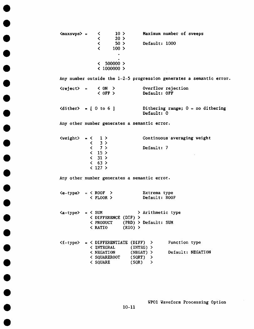
<maxswps> = < i0 >< 20 >< 50 >< I00 >
< 500000 >< I000000 >
Maximum number of sweeps
Default: i000
Any number outside the 1-2-5 progression generates a semantic error¯
<reject> = < ON >< OFF >
Overflow rejectionDefault: OFF
<dither> = [ 0 to 6 ] Dithering range; 0 = no ditheringDefault: 0
Any other number generates a semantic error¯
<weight> = <<<
1 >3>7>
< 15 >< 31 >< 63 >< 127 >
Continuous averaging weight
Default: 7
Any other number generates a semantic error¯
<e-type> = < ROOF >< FLOOR >
Extrema typeDefault: ROOF
<a-type> = < SUM > Arithmetic type< DIFFERENCE (DIF) >< PRODUCT (PRD) > Default: SUM< RATIO (RIO)
<f-type> = < DIFFERENTIATE (DIFF) < INTEGRAL (INTEG) < NEGATION (NEGAT) < SQUAREROOT (SQRT) < SQUARE (SQR)
Function type
Default: NEGATION
i0-IIWPOI Vaveform Processing Option

<s-type> =<I><3><5><7><9>
Smoothing type
Default: 3-pt smoothing
Any other number generates a semantic error.
<m-fact> = [ 0.01 to 9.99 ] Multiplication factorDefault: 1.00
Any value smaller than 0.01 or greater than 9.99 is adapted to thenearest legal value.
<a-const> = [ -9.99 to 9.99 ] Additive constantDefault: 0.00
Any value smaller than 0.01 or greater than 9.99 is adapted to thenearest legal value.
NOTE: <a-const> is interpreted as the number of vertical divisionsof <sourcel>
Whenever a parameter is not specified, the default value issubstituted.
Examples:
RDF,AVG,SUMMED,,C2 Configures the SELECTed trace (which must beFUNCTION E or FUNCTION F) for the summedaveraging of CHANNEL 2 with a maximum of 1250data points over IO00 sweeps. By default,overflow rejection and dithering are off.
RDF,ARI,PRD,2500,CI,MD,2.00,1.00
Configures the SELECTed trace to compute thewaveform 2.00*(CHANNEL 1 + 1 div)*Memory_D. maximum of 2500 of data points (equidistantlydistributed over the screen) are to be used.
REDEFINE,FNC,INTEG,25000,FE
Configures the SELECTed trace (which must beFUNCTION F, since FUNCTION E is specified assource waveform) to compute the integral over
the waveform in FUNCTION_E, using a maximum of25000 data points. Note that the use of 25000data points implies that all data points onthe screen are to be used, regardless of thetime-base setting.
10-12WPOI Waveform Processing Option

4) The READ commands of Section 7.6.5 have been extended to readFUNCTIONS E and F:
READ (RD) < FUNCTION E.DESC (FE.DE) < FUNCTION-F.DESC (FF.DE)
READ (RD) , < FUNCTION E.DATA (FE.DA) > , <Parameter list>< FUNCTION-F.DATA (FF.DA)
READ (RD) , FUNCTION E. TIME (F E.TI) >< FUNCTION-F.TIME (FF.TI)
READ (RD) , < FUNCTION E.*< FUNCTION-F.*
(FE.*) > , <Parameter list>(FF.*) >
<Parameter list> = <intval> , <# values> , <addr> , <sweep #>
See Section 7.6.5 for more detailed explanations.
10.4 Additional Values in the Descriptors of Processed Waveforms
The waveform descriptor contains all the information needed tocorrectly interpret the waveform data. The parameters which describethe raw data records are explained in Section 7.7; they are still validfor processed waveforms. However, some additional parameters describethe processing which was applied to obtain the current waveform.
IMPORTANT: The parameters in the following list have NO meaning if the"Data Processing" byte (number 34 of the descriptor record)is set to 99 (raw data).
In the following list, each parameter is identified by its (decimal)address relative to the beginning of the descriptor, and by the numberof bits. Data values shown are always in decimal.
Pos. Size
36 16-bit
38 16-bit
40 - 63
64 8-bit
Meaning
256*Power of volts (see explanation in Section 10.5).
256*Power of seconds (see explanation in Section 10.5).
Reserved
Identity of function waveform; 4 = E, 5 = F.
10-13WPOI Waveform Processing Option

65 B-bit
66 B-bit
67 8-bit
68 B-bit
69 8-bit
70 32-bit
74 16-blt
76 16-bit
78 16-blt
80 8-bit
81 8-bi t
82 - 97
98 32-bit
102 32-bit
Function type.0 = Average2 = Arithmetic4 = Smoothing
1 = Extrema3 = Functions
Sub-function type, depending on function type. Takes onvalues between 0 and (n-l), where n is the number sub-functions possible. The order is the same as in thesub-function lists of Section 10.3.
Primary source of this waveform.0 = CHANNEL 1 1 = CHANNEL 22 = Memory C 3 = Memory D4 = FUNCTION E
Secondary source of this waveform (arithmetic only), withthe same interpretation as the previous byte (67).
Continuous averaging weight.0=I : 1 1=1:32 = 1 : 7 3 = 1 : 154 = 1 : 31 5 = 1 : 636 = 1 : 127
Maximum number of sweeps (summed averaging and extrema).
Multiplication factor * I00
Additive constant * I00
Maximum number of data points = <maxpts> in the REDEFINEcommand.
Reject (summed averaging only).0 = Reject off 1 = Reject on
Dithering (summed averaging only).0 = No ditheringOtherwise = approximate number of
bits, corresponding toexcursion.
ADC least significantthe maximum dithering
Reserved
Actually acquired number of sweeps (summed averaging andextrema).
Number of acquired waveforms with overflows (summedaveraging).
10-14WPOI Waveform Processing Option

106 32-bit
110 32-bit
114 16-bit
116 16-bit
Number of acquired waveforms with under-flows (summedaveraging).
Number of rejected waveforms (summed averaging with RejectON).
Number (+ 1) of data points used in the computation of thisdata record (may be less than <maxpts>).
Ratio of the number of data points in the source waveformover the number of data points used.
118 - 149 Reserved
10.5 Vertical Scaling Units
With the introduction of waveform processing functions, such asmultiplication, division, square-root, integration and differentiation,which alter the vertical scaling units, a more general system for thevertical scales must be introduced. Three variables are now involved:
"fgain" (byte 0) = "fixed vertical gain" differently, by dropping(Compare with Section 7.7).
now interpreted slightlythe notion of volts
22 = 5 mU/div 23 = I0 mU/div24 = 20 mU/div 25 = 50 mU/div
..... 31 = 5 U/div
Where U now stands for a general unit, which may be aproduct of a power of volts and of a power of seconds.
"P V" (bytes 36 + 37) = 256*power of volts"P-s" (bytes 38 + 39) = 256*power of seconds
Thus, U = Volts**(P_V/256) * Seconds**(P_s/256).
NOTE: Whenever the WP01 waveform processing option is installed, "P V"and "P s" are always valid, even in raw data records (see the followingexample). However, in software versions without waveform processing,they cannot be relied upon. (Of course, in these cases the verticalscales are always in volts).
10-15WP01Waveform Processing Option
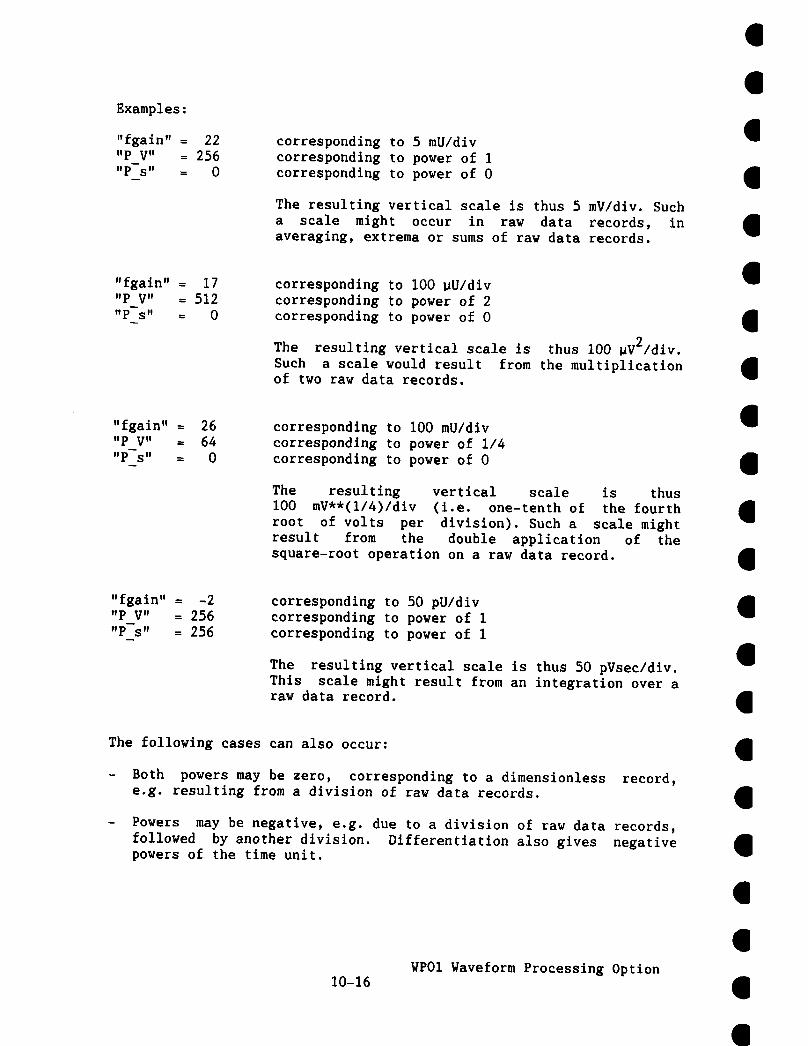
Examples:
"fgain" = 22"P V" = 256"P-S" = 0
corresponding to 5 mU/divcorresponding to power of 1corresponding to power of 0
The resulting vertical scale is thus 5 mV/div. Sucha scale might occur in raw data records, inaveraging, extrema or sums of raw data records.
"fgain" = 17"P V" = 512"P-s" = 0
corresponding to I00 ~U/divcorresponding to power of 2corresponding to power of 0
The resulting vertical scale is thus i00 ~V2/div.Such a scale would result from the multiplicationof two raw data records.
"fgain" = 26"P V" = 64"P-s" = 0
corresponding to i00 mU/divcorresponding to power of 1/4corresponding to power of 0
The resulting vertical scale is thusI00 mV**(I/4)/div (i.e. one-tenth of the fourthroot of volts per division). Such a scale mightresult from the double application of thesquare-root operation on a raw data record.
"fgain" = -2"P V" = 256"P-s" = 256
corresponding to 50 pU/divcorresponding to power of 1corresponding to power of 1
The resulting vertical scale is thus 50 pVsecldlv.This scale might result from an integration over araw data record.
The following cases can also occur:
- Both powers may be zero, corresponding to a dimensionless record,e.g. resulting from a division of raw data records.
Powers may be negative, e.g. due to a division of raw data records,followed by another division. Differentiation also gives negativepowers of the time unit.
10-16WP01Waveform Processing Option
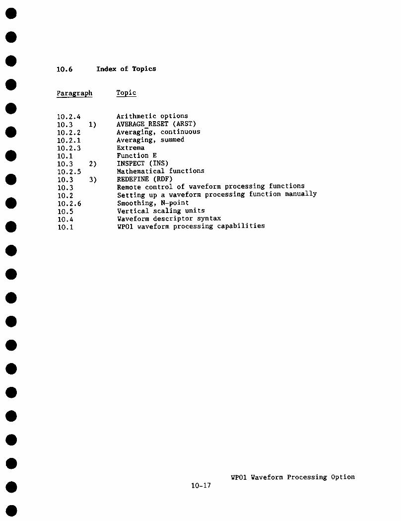
10.6 Index of Topics
Paragraph Topic
10.2.410.310.2.210.2.110.2.3I0.i10.310.2.510.310.310.210.2.610.510.4i0.I
i)
2)
3)
Arithmetic optionsAVERAGE RESET (ARST)Averaging, continuousAveraging, summedExtremaFunction EINSPECT (INS)Mathematical functionsREDEFINE (RDF)Remote control of waveform processing functionsSetting up a waveform processing function manuallySmoothing, N-pointVertical scaling unitsWaveform descriptor syntaxWPOI waveform processing capabilities
10-17WP01Waveform Processing Option

0
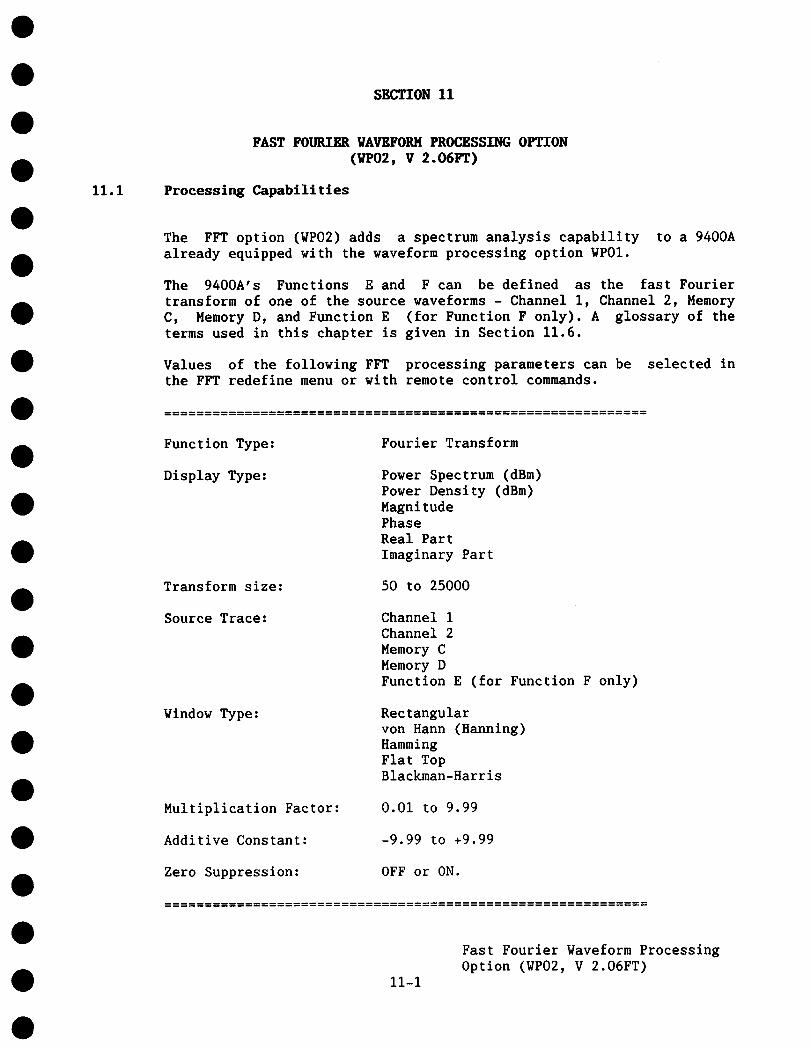
SECTION Ii
11.1
FAST FOURIER WAVEFORM PROCESSING OPTION(WP02, V 2.06FT)
Processing Capabilities
The FFT option (WP02) adds a spectrum analysis capability to a 9400Aalready equipped with the waveform processing option WP01.
The 9400A’s Functions E and F can be defined as the fast Fouriertransform of one of the source waveforms - Channel 1, Channel 2, MemoryC, Memory D, and Function E (for Function F only). A glossary of theterms used in this chapter is given in Section 11.6.
Values of the following FFT processing parameters can be selected inthe FFT redefine menu or with remote control commands.
Function Type:
Display Type:
Transform size:
Source Trace:
Window Type:
Multiplication Factor:
Additive Constant:
Zero Suppression:
Fourier Transform
Power Spectrum (dBm)Power Density (dBm)MagnitudePhaseReal PartImaginary Part
50 to 25000
Channel 1Channel 2Memory CMemory DFunction E (for Function F only)
Rectangularvon Hann (Hanning)HammingFlat TopBlackman-Harris
0.01 to 9.99
-9.99 to +9.99
OFF or ON.
11-1
Fast Fourier Waveform ProcessingOption (WP02, V 2.06FT)

The 9400A’s Function F can also be defined as the Power Average of theFFT computed by Function E.
Values of the following FFT processing parameters can be selected inthe FFT Power Average redefine menu or with remote control commands:
Function Type:
Display Type:
Transform Size:
Source Trace:
Max number of sweeps:
FFT Power Average
Power Spectrum (dBm)Power Density (dBm)Magnitude
same as Function E
Function E
i0 to 200
All WPOISmoothing)processing.
functions (Averaging, Extrema, Arithmetic, Functions andcan be applied to waveforms either before or after the FFT
Menus and front panel controls related to FFT are similar to thecorresponding WPOI controls (see Section i0.i).
Remote control commands related to FFT provide for the definition ofprocessing and the readout of waveform data and status, as well as theloading of reference waveforms into the 9400A’s memories (C, D).The commands are similar to the corresponding WP01 commands (seeSections 7, 10.3 and 11.3).
Spectra are computed over the full length of the source time domainwaveform.
Sub-sampling of the source waveform is available (with the TransformSize option in the FFT menu), so that the the computation speed can betraded against the frequency range.
Spectra are displayed with frequency axes running from zero to Nyquistfrequency, over 5 or 6.25 divisions, with the frequency scale factor ina I-2-5 sequence.
The Time Magnifier operates on the FFT output traces as a FrequencyMagnifier (up to 100 times).
11-2
Fast Fourier Waveform ProcessingOption (WP02, V 2.06FT)

The Display Control knobs provide vertical expansion (up to 10 times)and vertical position control.
To read the amplitude and frequency of the data point, the Marker canbe moved over into the frequency domain by going beyond the right handedge of the time domain waveform.
The Time Cursors can be moved beyond the right hand edge of the timedomain waveform and thus become Frequency Cursors, providingsimultaneous readout of frequency difference and of amplitudedifference between two points on each frequency domain trace.
Table 11.1 Display Types
Display type Unit Vertical positionof zero
Power Spectrum dBm (mark)Power Density spectrum dBm (mark)Magnitude V -3 divPhase degree 0 divReal Part V 0 divImaginary Part V 0 div
Note: Vertical position of 0 dBm varies with the source waveform’sgain. A mark at the left hand edge of the screen indicates the dBmlevel of a trace. Generally, a sinusoidal source waveform of 8 divpeak-peak will give a spectrum point of about +3 div at any gain.
Since the computation of FFT may take up to 1 minute (for a TransformSize of 25000 points), it is possible to interrupt an undesired FFTeither by turning off the corresponding trace(s) or by pushing theRedefine button, if the FFT trace is the selected trace.
11.2 Modification to WPO1 Functions
With the option WP02 (FFT) installed, the WP01 functions are modifiedas follows:
When any WP01 function operates on a frequency domain waveform (aresult of FFT processing), the Max # of Points value selected in themenu of the function is ignored. Instead, the number of points of thefrequency domain waveform is used for further processing.
11-3
Fast Fourier Waveform ProcessingOption (WP02, V 2.06FT)

11.3 FFT Processing Examples
Example: spectrum of the 9400A Probe Calibrator waveform.
I) Connect the 9400A calibration signal (976.6 Hz, 1.0 V pp squarewave) to the channel 1 input.
2) If you use a xlO probe, select Panel STATUS and adjust the Set ChlAttenuator to )d0.
Set Channel i volts/div to 20 mV/div (for)dO probe), AC, 1
Set the Channel 1 offset to a value near 0.
3) Select a time base of 1 msec/div.
4) Adjust the triggering conditions as follows: Chl, AC coupling,
normal; trigger level about 0 div.
You should obtain a repetitive display of almost I0 periods of asquare wave, 5 divisions peak-to-peak.
5) Turn on and Select Function E
6) Redefine Function E as follows:
Function Class:Display Type:Transform Size:Source Trace:Window Type:Multiplication Factor:Additive Constant:Zero Suppression:
Fourier TransformMagnitude1250Chan 1Rectangular1.00+0.00 divON
Notice that at the bottom of the menu page the effective number ofpoints, N = 1250, and the Nyquist frequency = 62.5 kHz aredisplayed.
11-4
Fast Fourier Waveform ProcessingOption (VP02, V 2.06FT)
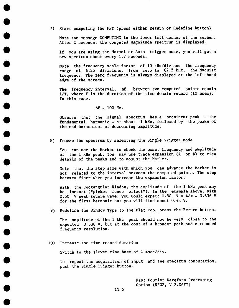
7) Start computing the FFT (press either Return or Redefine button)
Note the message COMPUTING in the lower left corner of the screen.After 2 seconds, the computed Magnitude spectrum is displayed.
If you are using the Normal or Auto trigger mode, you will get anew spectrum about every 1.7 seconds.
Note the frequency scale factor of i0 kHz/div and the frequencyrange of 6.25 divisions, from zero to 62.5 kHz, the Nyquistfrequency. The zero frequency is always displayed at the left handedge of the screen.
The frequency interval, 6f, between two computed points equalsI/T, where T is the duration of the time domain record (i0 msec).In this case,
Af = I00 Hz.
Observe that the signal spectrum has a prominent peak - thefundamental harmonic - at about 1 kHz, followed by the peaks ofthe odd harmonics, of decreasing amplitude.
8) Freeze the spectrum by selecting the Single Trigger mode
You can use the Marker to check the exact frequency and amplitudeof the 1 kHz peak. You may use trace expansion (A or B) to viewdetails of the peaks and to adjust the Marker.
Note that the step size with which you can advance the Marker isnot related to the interval between the computed points. The stepbecomes finer when you increase the expansion factor.
With the Rectangular Window, the amplitude of the 1 kHz peak maybe inexact ("picket fence effect"). In the example above, with0.50 V peak square wave, you would expect 0.50 V * 4/K = 0.636 Vfor the first harmonic but you will find about 0.43 V.
9) Redefine the Window Type to the Flat Top, press the Return button.
The amplitude of the 1 kHz peak should now be very close to theexpected 0.636 V, but at the cost of a broader peak and a reducedfrequency resolution.
1o) Increase the time record duration
Switch to the slower time base of 2 msec/div.
To repeat the acquisition of input and the spectrum computation,push the Single Trigger button.
11-5
Fast Fourier Waveform ProcessingOption (WF02, V 2.06FT)

The frequency resolution is now increased (the harmonic peaks arefurther apart), but the frequency range is reduced.
You can use the Marker to check the Nyquist frequency of 25.0 kHzat the right hand edge of the spectrum trace, which agrees withthe value displayed in the FFT menu.
11) Switch to 10 msec/div and push the Single Trigger button tofurther increase the time record duration.
The Nyquist frequency is now 6.25 kHz, so that only the harmonics1, 3 and 5, a~. approximately 1, 3 and 5 kHz fit into the frequencyrange. The 7"n harmonic, at about 7 kHz, has been aliased (foldedback) into the peak visible at 2 * 6.25 - 7 = 5.5 kMz. Furtheraliased harmonics of decreasing amplitude are also visible betweenthe original peaks.
12) Redefine the Display Type to Power Spectrum, and the Window Typeback to Rectangular.
You now see the harmonics on the logarithmic scale, at 10 dB/dlv.
Look at the broad skirts exhibited by the peaks: this is theleakage of the signal energy of each peak into the neighboringfrequency bins.
13) Redefine the Window Type to von Hann (also called Hanning)
The skirts are reduced considerably; the leakage is diminished.
14) Redefine the Transform size to 2500
You will obtain N = 2500 and the Nyquist frequency of 125 kHz,while the interval between the points (bins) will remain unchangedat 1/0.01 sec = 100 Hz.
15) Define Function F as the FFT Power Average of Function E
Using the Normal or Auto trigger mode, you can average up to 200spectra and see the intermediate or final average on a linearscale (Magnitude) or dBm scale (Power Spectrum or Power Density).
11-6
Fast Fourier Waveform ProcessingOption (WP02, V 2.06FT)

16) Experiment
Try other tlme-base settings, display modes, numbers of points,window types and signals, to become familiar with the system. Trycombinations of FFT and the WPOI processing functions.
You can define both Functions E and F as FFT of the same sourcewaveform, but with different parameters, and compare the resultingtraces.
11.4 Remote Control of FFT Processing
Consult Sections 7 and 10.3 - 10.4 for general information on remotecontrol using either the GPIB or the RS-232-C interface. The additionalforms of commands specific to the FFT option and the related fields ofthe Waveform Descriptor are described below.
11.4.1 Remote Commands
The ’Redefine’related to FFT:
command has been extended to accept the parameters
REDEFINE (RDF), FFT, <disptype>, <maxpts>, <source>,<m_fact>, <a_const>, <z_suppr>
The parameters have the following options:
<disp_type> = < POWER SPECTRUM (PWS) > (default)< POWER-DENSITY (PWD) >< MAGNITUDE (MAG) >< PHASE (PHASE) >< REAL PART (REAL) >< IMAGINARY PART (IMAG) >
<maxpts> = < 5O >< 125 >< 250 >< 625 >< 1250 >< 2500 >< 6250 >< 12500 >< 25000 >
(default)
Any other number generates a semantic error.
<window>,
11-7
Fast Fourier Waveform ProcessingOption (WP02, V 2.06FT)

<source> = < CHANNEL 1 (Cl) (default)< CHANNEL-2 (C2) < MEMORY C (MC) < MEMORY-D (MD) < FUNCTION E (FE)
NOTE: FUNCTION E can be a source only for FUNCTION_F.
<window> = < RECTANGULAR (RECT) (default)
< V0N HANN (HANN) < HAMMING (HAHN) < FLAT TOP (FLT) < BLACKMAN HARRIS (BH)
<m fact> = 0.01 to 9.99 (default = 1.0)
Multiplication factor applied towaveform before FFT computation.
the source
<a const> = -9.99 to 9.99 (default = 0.0)
Additive constant (divisions) applied to thesource waveform before multiplication.
<z_suppr> = <OFF><ON> (default)
If ON, the DC component of the sourcewaveform is forced to O.
The ’redefine’ command has also been extended to accept the parametersrelated to the FFT Power Average:
REDEFINE (RDF), FFT AVG (FFTA), <dlsp_type>, <nsweeps>
The parameters have the following options:
<disp_type> = < POWER SPECTRUM (PWS) < POWER-DENSITY (PWD) < MAGNITUDE (MAG)
(default)
<nsweeps> = < I0 >< 20 >< 50 >< I00 >< 200 > (default)
Any other number generates a semantic error.
11-8
Fast Fourier Waveform ProcessingOption (WP02, V 2.06FT)

NOTE: This definition can be applied only to Function F. It will beexecuted only if Function E is defined as FFT (any display mode). Thenumber of points will be that of the output of the FFT (i.e. N/2).
Examples:
RDF,FFT,MAG,1250,CI
Redefines the SELECTed trace (E or F) for theFFT of Channel 1 with maximum 1250 points,displaying the Magnitude on a linear scale.
Default settings are applied to theremaining parameters (Rectangular window,m fact = 1.0, a const = 0.0, zero suppression
ON).
RDF,FFT,PNS,625,C2,BH,2.0,,OFF
Redefines the SELECTed trace (E or F) for theFFT of Channel 2 with maximum 625 points,displaying the Power Spectrum on alogarithmic (dBm) scale. Window Type Blackman-Harris, m fact = 2.0, a_const = 0.0,zero suppression is OFF.
RDF,FFTA,PWD,20
Redefines the SELECTed trace (must be F) forthe FFT Power Average of the FFT computedsimultaneously by Function E. Number ofsweeps is 20.
11.4.2 Additional Values in the Descriptors of FFT Processed Waveforms
The oscilloscope waveform and descriptors can be read into a hostcomputer (see Section 7.6.5).
With the WP02 option, the Waveform Descriptor length is unchanged(150 bytes). However, in addition to the Descriptor field values definedin Section 7.7 and 10.4, the following fields have new or additionalvalues pertaining to the results of FFT processing:
11-9
Fast Fourier Waveform ProcessingOption (WP02, V 2.06FT)

Pos
9
i0
34
36
38
Size
8-bit
8-bit
8-bit
16-bit
16 bit
Meaning
Time base (sec/div):
4 .. 36: see Section 7.7
Frequency base (Hz/div):
59 = 5 mHz60 = I0 mHz61 = 30 mHz62 = 50 mHz.e.
86 = 5 MHz87 = I0 MHz88 = 20 MHzeee
91 = 0.2 GHz92 = 0.5 GHz
Displayed Record Length
59 .. 86 = 12500 points87 = i0000 points
88 .. 92 = 12500 points
Sampling interval (sec/point):
II .. 45: see Section 7.7
Frequency interval (Hz/point):
59 = 2.0 ~Hz60 = 5.0 ~Hz61 = 10.0 wHz62 = 20.0 ~Hze,e
91 = 0.I MHz92 = 0.2 MHz
Data processing of this record
5 = FFT6 = FFT AVERAGE
Units: code for power of volts
code = 256 * power
Units: code for power of seconds
II-i0
Fast Fourier Waveform ProcessingOption (WP02, V 2.06FT)

11.5
11.5.1
40 16 bit
42 8 bit
56 8 bit
82 8 bit
89 8 bit
118-119 16 bit
code = 256 * power
Units: code for power of arbitrary unit
code = 256 * power
Units: identity of arbitrary unit
0 = undefined1 = dB4 = degrees
Display Type:
0 = dBm Power Spectrum1 = dBm Power Density2 = Magnitude3 = Phase4 = Real Part5 = Imaginary Part
Window Type:
0 = rectangularI =von Hann2 = Hamming3 = Flat Top4 = Blackman-Harris
Zero Suppression:
0 = OFF1 = ON
Ratio of the number of data points of theexpanded waveform over the number of datapoints computed.
FFT Application Hints
Some practical suggestions:
(I) To increase the frequency resolution, increase the length of thetime domain waveform record (i.e. use a slower time base).
(2) To increase the frequency range, increase the effective samplingfrequency (i.e. increase the Transform Size).
ii-II
Fast Fourier Waveform ProcessingOption (WP02, V 2.06FT)

(3) With transient signals use the Rectangular window. You should adjustthe time base and the triggering conditions so that the transient iscompletely contained in the time domain window (i.e. on the screen).
(4) For the best amplitude accuracy of isolated spectrum peaks, use theFlat Top window.
(5) For the best reduction of leakage and good detection of small peaksseveral bins away from a large peak, use the Blackman-Harris window.
(6) For moderate improvement of amplitude accuracy and of leakagerejection, use the von Hann or Hamming window.
(7) If your time domain signal is repetitive but noisy, preventing youfrom having a stable trigger, you can define Function E as the FFTof the signal channel and Function F as the FFT Power Average ofFunction E to obtain a stable spectrum of the input signal.
(8) You can display the FFT Power Average either on a linear scale(Magnitude) or on a dBm scale (Power Spectrum or Power Density).
11.5.2 Relationships of 9400A FFT output vaveforms to the FFT computation steps
For comparison of the 9400A’s FFT results with those obtained from otherFFT instruments the following information may be useful:
(I) In the 9400A’s FFT computation, the first step is the sub-samplingof the source waveform. Data points for the FFT calculation aremeasured at regular intervals over the full length of the waveformdisplayed on the screen.
You can select the maximum transform size in the FFT menu or viaremote control. The actual transform size, N, is selected to beequal to or smaller than the Displayed Record Length (seeTable 5.1). Exception: you may get a 125 point transform when youhave specified 50 points.
The sub-sampling interval and the actual transform size selectedprovide the frequency scale factor in a 1-2-5 sequence.
11-12
Fast Fourier Waveform ProcessingOption (WP02, V 2.06FT)

(2) The second step issub-sampled sourceselected factor.
the addition of the selected constant to thewaveform, followed by multiplication by the
(3) The third step is the multiplication of the source waveform by theselected window function.
(4) The fourth step is the computation of FFT, usingimplementation of the DFT (Discrete Fourier Transform)
a fast
k=N-iI
~
n*kX = x*W
n N kk=0
where xk
Xn
N
is a complex array whose real part is the modified sourcetime domain waveform, and whose imaginary part is 0
is the resulting complex frequency domain waveform
(-j * 2 * rJN)
is the number of points in xk and Xn
The generalized FFT algorithm, implemented in the 9400A, works on Nwhich need not be a power of 2.
(5) The fifth step is the division of the resulting complex vector Xby the coherent gain of the window function, to compensate for th~loss of the signal energy due to windowing. This compensationprovides accurate amplitude values for isolated spectrum peaks.
The real part of Xn is symmetricis:
about the Nyquist frequency, that
Rn = RN_n
while the imaginary part is anti-symmetric, that is
I n = _ IN_n
11-13
Fast Fourier Waveform ProcessingOption (WP02, V 2.06FT)
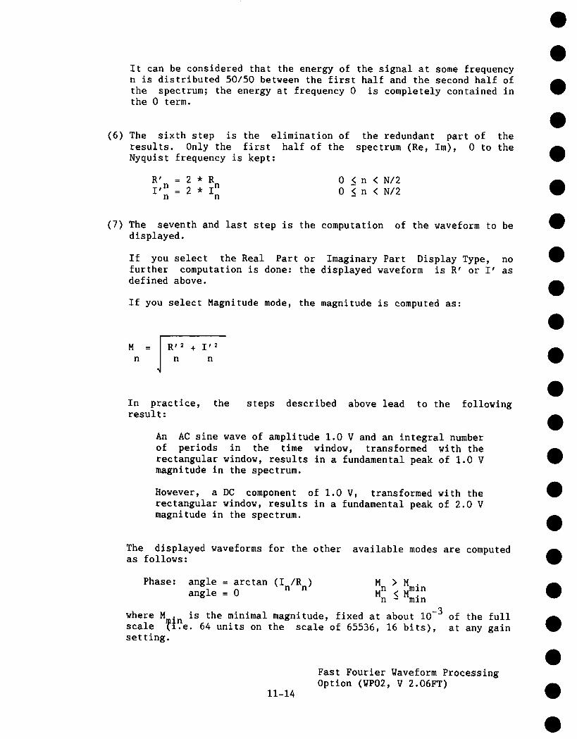
It can be considered that the energy of the signal at some frequencyn is distributed 50/50 between the first half and the second half ofthe spectrum; the energy at frequency 0 is completely contained inthe 0 term.
(6) The sixth step is the elimination ofresults. Only the first half of theNyquist frequency is kept:
the redundant part of thespectrum (Re, Im), 0 to the
R’ = 2 * ~n 0 < n < N/2I ’n = 2 * 0 < n < N/2n n -
(7) The seventh and last step is the computation of the waveform to bedisplayed.
If you select the Real Part or Imaginary Part Display Type, nofurther computation is done: the displayed waveform is R’ or I’ asdefined above.
If you select Magnitude mode, the magnitude is computed as:
!M = | R’2 + I’2
n~ n n
In practice, the steps described above lead to the followingresult:
An AC sine wave of amplitude 1.0 V and an integral numberof periods in the time window, transformed with therectangular window, results in a fundamental peak of 1.0 Vmagnitude in the spectrum.
However, a DC component of 1.0 V, transformed with therectangular window, results in a fundamental peak of 2.0 Vmagnitude in the spectrum.
The displayed waveforms for the other available modes are computedas follows:
Phase: angle = arctan (In/Rn) ~n > M .angle = 0 < Mm~n
n - mln
where M is the minimal magnitude, fixed at about 10-3 of the fullscale ~e. 64 units on the scale of 65536, 16 bits), at any gain
setting.
11-14
Fast Fourier Waveform ProcessingOption (WP02, V 2.06FT)

dBm Power Spectrum:
Log PS = 10 * logn 10
M2
n
ref
= 20 * logI0
Mn
Mref
where M r = 0.316 V (that is, 0 dBm is defined as the sine wave of0.316 V ~k or 0.224 V RMS, giving 1.0 mW into 50 9).
Note that the "dBm Power Spectrum" could also be called the "dBmMagnitude" as suggested by the formula above.
dBm Power Density:
Log PD = log PS - I0 * log (ENBW * Af)n n I0
where ENBW is the equivalent noise bandwidth of the filtercorresponding to the selected window
Af is the current frequency resolution (bin width)
The FFT Power Average (Function F only) takes the complex frequencydomain data R’ n, I’ , generated by Function E in step 6 above,computes the square o~ the magnitude
M2=R, 2+i , 2n n n
and collects the result in a buffer.
(8) In the case of an FFT Power Average the final step is thecomputation of the selected Display Type format (Magnitude, PowerSpectrum, Power Density).
11.5.3 Computation speed of FFT
In the 9400A the Fourier transform computation takes about 1.7 sec for a1250 point FFT and just under one minute for a 25000 point FFT. Thesetimes depend somewhat on the Window Type and the Display Type selected.
11-15
Fast Fourier Waveform ProcessingOption (WP02, V 2.06FT)
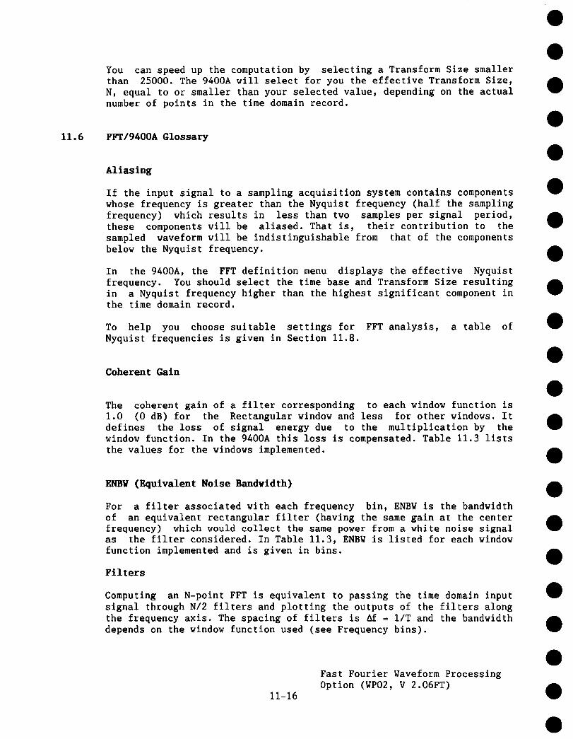
You can speed up the computation by selecting a Transform Size smallerthan 25000. The 9400A will select for you the effective Transform Size,N, equal to or smaller than your selected value, depending on the actualnumber of points in the time domain record.
11.6 FFT/9400A Glossary
Aliasing
If the input signal to a sampling acquisition system contains componentswhose frequency is greater than the Nyquist frequency (half the samplingfrequency) which results in less than two samples per signal period,these components will be aliased. That is, their contribution to thesampled waveform will be indistinguishable from that of the componentsbelow the Nyquist frequency.
In the 9400A, the FFT definition menu displays the effective Nyquistfrequency. You should select the time base and Transform Size resultingin a Nyquist frequency higher than the highest significant component inthe time domain record.
To help you choose suitable settings for FFT analysis, a table ofNyquist frequencies is given in Section 11.8.
Coherent Gain
The coherent gain of a filter corresponding to each window function is1.0 (0 dB) for the Rectangular window and less for other windows. defines the loss of signal energy due to the multiplication by thewindow function. In the 9400A this loss is compensated. Table 11.3 liststhe values for the windows implemented.
ENBV (Equivalent Noise Bandwidth)
For a filter associated with each frequency bin, ENBW is the bandwidthof an equivalent rectangular filter (having the same gain at the centerfrequency) which would collect the same power from a white noise signalas the filter considered. In Table 11.3, ENBW is listed for each windowfunction implemented and is given in bins.
Filters
Computing an N-point FFT is equivalent to passing the time domain inputsignal through N/2 filters and plotting the outputs of the filters alongthe frequency axis. The spacing of filters is Af = I/T and the bandwidthdepends on the window function used (see Frequency bins).
11-16
Fast Fourier Waveform ProcessingOption (WP02, V 2.06FT)

Frequency bins
The FFT algorithm takes a discrete source waveform, defined over Npoints, and computes N complex Fourier coefficients, which areinterpreted as harmonic components of the input signal.
For a real source waveform (imaginary part equals 0), there are only N/2independent harmonic components.
The FFT corresponds to analyzing the input signal with a bank of N/2filters, all having the same shape and width, and centered at N/2discrete frequencies. Each filter collects the signal energy fallinginto the immediate neighborhood of its center frequency, and thus it canbe said that there are N/2 "frequency bins".
The distance, in Hz, between the center frequencies of the bins isalways
af = I/T
where T is the duration of the time domain record in seconds.
The width of a bin is equal to Af.
The width of the main lobe of the filter centered at each bin depends onthe window function used. With the Rectangular window, the width at-3.92 dB is 1.0 bins. Other windows have wider main lobes (consultTable 11.3).
Frequency Range
The range of frequencies computed and displayed in the 9400A is from 0Hz at the left hand edge of the screen to the Nyquist frequency at 5 or6.25 divisions.
Frequency Resolution
In a narrow sense, the frequency resolution is equal to the bin width,af. That is, if the input signal changes its frequency by af, thecorresponding spectrum peak will be displaced by ~f. For smaller changesof frequency, only the shape of the peak will change.
However, the effective frequency resolution (i.e. the ability toactually resolve two signals having close frequencies) is furtherlimited by the use of window functions. The ENBW value of all windowsother than the rectangular is greater than ~f, i.e. greater than the binwidth. Table 11.3 lists the ENBW value for the windows implemented.
11-17
Fast Fourier Waveform ProcessingOption (WP02, V 2.06FT)
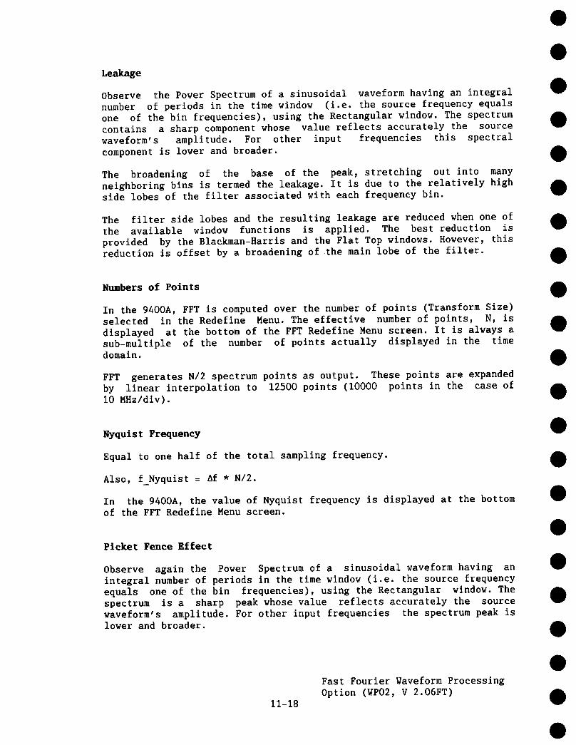
Leakage
Observe the Power Spectrum of a sinusoidal waveform having an integralnumber of periods in the time window (i.e. the source frequency equalsone of the bin frequencies), using the Rectangular window. The spectrumcontains a sharp component whose value reflects accurately the sourcewaveform’s amplitude. For other input frequencies this spectralcomponent is lower and broader.
The broadening of the base of the peak, stretching out into manyneighboring bins is termed the leakage. It is due to the relatively highside lobes of the filter associated with each frequency bin.
The filter side lobes and the resulting leakage are reduced when one ofthe available window functions is applied. The best reduction isprovided by the Blackman-Harris and the Flat Top windows. However, thisreduction is offset by a broadening of the main lobe of the filter.
Numbers of Points
In the 9400A, FFT is computed over the number of points (Transform Size)selected in the Redefine Menu. The effective number of points, N, isdisplayed at the bottom of the FFT Redefine Menu screen. It is always asub-multiple of the number of points actually displayed in the timedomain.
FFT generates N/2 spectrum points as output. These points are expandedby linear interpolation to 12500 points (I0000 points in the case of10 MHz/div).
Nyquist Frequency
Equal to one half of the total sampling frequency.
Also, f Nyquist = Af * N/2.
In the 9400A, the value of Nyquist frequency is displayed at the bottomof the FFT Redefine Menu screen.
Picket Fence Effect
Observe again the Power Spectrum of a sinusoidal waveform having anintegral number of periods in the time window (i.e. the source frequencyequals one of the bin frequencies), using the Rectangular window. Thespectrum is a sharp peak whose value reflects accurately the sourcewaveform’s amplitude. For other input frequencies the spectrum peak islower and broader.
11-18
Fast Fourier Waveform ProcessingOption (WP02, V 2.06FT)

Its highest point can be lower by 3.92 dB (1.57 times) when the sourcefrequency is half way between two bin frequencies. This variation of thespectrum magnitude is called the Picket Fence Effect (the loss is calledthe Scallop Loss).
All window functions compensate this loss to some extent but the FlatTop window provides the best correction (see Table 11.3).
Power Spectrum
The Power Spectrum (V 2) is the square of the Magnitude spectrum.
The 9400A displays the Powe~ Spectrum on the dBm scale, with 0 dBmcorresponding to (0.316 Vpeak)
Pover Density spectrum
The Power Density Spectrum (V2/Mz) is the Power Spectrum divided by theproduct of the equivalent noise bandwidth of the filter and thefrequency bin width in Hz.
The 9400A displays the Power Density spectrum on the dBm scale, with
0 dBm corresponding to (0.316 Vpeak)-/Hz.
Sampling Frequency
In the 9400A the time domain records are acquired at samplingfrequencies which depend on the selected time base (consult Table 5.1).
Before FFT, the time domain record may be sub-sampled. If the selectednumber of points is lower than the displayed record length (Table 5.1),the total sampling frequency will be reduced.
The total sampling frequency equals twice the Nyquist frequency(displayed in the FFT Redefine Menu).
Scallop Loss
Loss associated with the picket fence effectwindows implemented).
(listed in Table 11.3 for
11-19
Fast Fourier Waveform ProcessingOption (WP02, V 2.06FT)

Window Functions
All window functions implemented in the WP02 package belong to the sumof cosines family with one to three non-zero cosine terms:
m=M-I
w = a * cos 0 _< k < Nk m N
!
m=O
where H=3
am
N
k
is the maximum number of terms
are the coefficients of the terms
points of theis the number ofwaveform
is the time index
coefficients.Table 11.2 lists the am
source
The window functions, seen in the time domain are symmetric about thepoint k = N/2, (mid-screen on the 9400A) where they all have a peakamplitude of 1.0.
Table 11.2 Coefficients of window functions
Window type a0 aI a2
Rectangular 1.0 0.0 0.0
yon Hann 0.5 -0.5 0.0
Hamming 0.54 -0.46 0.0
Flat-Top 0.281 -0.521 0.198
Blackman-Harris 0.423 -0.497 0.079
11-20
Fast Fourier Waveform ProcessingOption (WP02, V 2.06FT)

Table 11.3 Window frequency domain parameters
Window type Highest Scallop ENBV Coherentside-lobe loss gain(dB) (dB) (bins) (dB)
Rectangular - 13 3.92 1.0 0.0
yon Hann - 32 1.42 1.5 - 6.02
Hamming - 43 1.78 1.37 - 5.35
Flat-Top - 44 0.01 2.96 -11.05
Blackman-Harris - 67 1.13 1.71 - 7.53
11.7 Errors and Warnings
Certain combinations of source waveform propertiesfunctions may result in an error or raise a warning.message is displayed at the top of the 9400A screen.
and processingThe appropriate
On Error, processing is abandoned.
On Warning, processing is performed, but the results are corrupted.
ERROR: FFT src wfm is in sequence mode.
FFT of sequence mode waveform has notabandoned.
been implemented. Processing
ERROR: FFT src wfm is in frequency domain.
FFT of a frequency domain waveform has not been implemented. Processingabandoned.
ERROR: FFT AVG src wfm not in freq domain.
FFT Power Average mode (Function F only) is active only if Function E defined as FFT. Processing abandoned.
You should define Function E as FFT.
11-21
Fast Fourier Waveform ProcessingOption (WP02, V 2.06FT)

WARNING: FFT src wfm (ils mode) extended.
In the Interleaved Sampling Mode, there are two time-base settings(I ~sec/div and 0.5 ~sec/div) in which the record of 25000 points shownon the screen is incomplete. Starting at the left hand edge of thescreen, 0.08 and 0.4 div respectively are blank. Before computing theFFT, the leftmost valid point of such records is copied leftward,through to the left edge of the screen. This will generate harmoniccomponents not present in the original record.
If possible, you should use the Single-shot mode before FFT at thesetime-base settings.
WARNING: FFT src wfm (roll mode) incomplete.
In the Roll Mode (time/div < 0.5 sec), you can stop the acquisition of trace before it fills the entire width of the screen. The remainingportion of the record is blank on the display, but the memory contentsremain undefined. FFT is computed on this partially undefined record.
You should avoid stopping the acquisition in this manner if you wish toobtain meaningful FFT results.
VARNING: FFT src vfm overlunderflov.
The source waveform has been clipped in amplitude, either in theacquisition (too high gain or inappropriate offset) or in the previousprocessing. The resulting FFT contains harmonic components which werenot present in the unclipped waveform.
You should repeat the acquisition or previous processing of the sourcewaveform, with changed settings.
11.8 Table of Nyquist Frequencies
FNyquist Number of SS/RIS Time/divPoints
25.000 mHz 50 SS I00 sec62.500 mHz 125 SS I00 sec
0.125 Hz 50 SS 20 sec0.125 Hz 125 SS 50 sec0.125 Hz 250 SS i00 sec
11-22
Fast Fourier Waveform ProcessingOption (WP02, V 2.06FT)

FNyquist
0.2500.2500.2500.250
0.6250.6250.6250.625
1.2501.2501.2501.2501.2501.250
2.5002.5002.5002.5002.5002.5002.500
6.2506.2506.2506.2506.2506.2506.250
12.50012.50012.50012.50012.50012.50012.50012.50012.500
Hz
HzHzHz
Hz
HzHzHz
Hz
HzHzHzHzHz
Hz
HzHzHzHzHzHz
HzHzHzHzHzHzHz
I.]z
HzHzHzHzHzHzHzHz
Number ofPoints
50i00250500
125250625
1250
50125250500
12502500
5Oi002505OO
i00025005000
12525O625
125025006250
12500
5O12525050O
125025005000
1250025000
3S/RIS Time/div
SS I0 secSS 20 secSS 50 secSS I00 sec
SS i0 secSS 20 secSS 50 secSS I00 sec
SS 2 secSS 5 secSS i0 secSS 20 secSS 50 secSS I00 sec
SS I secSS 2 secSS 5 secSS I0 secSS 20 secSS 50 secSS i00 sec
SS 1 secSS 2 secSS 5 secSS 10 secSS 20 secSS 50 secSS i00 sec
SS 200 msecSS 0.5 secSS 1 secSS 2 secSS 5 secSS I0 secSS 20 secSS 50 secSS i00 sec
11-23
Fast Fourier Waveform ProcessingOption (WP02, V 2.06FT)

FNyquist
25.00025.00025.00025.00025.00025.00025.00025.000
62.50062.50062.50062.50062.50062.50062.50062.500
0.1250.1250.1250.1250.1250.1250.1250.1250.125
0.2500.2500.2500.2500.2500.2500.2500.250
0.6250.6250.6250.6250.6250.6250.6250.625
Hz
HzHzHzHzHzHzHz
Hz
HzHzHzHzHzHzHz
kHzkHzkHzkHzkHzkHzkHzkHzkHz
kHzkHzkHzkHzkHzkHzkHzkHz
kHzkHzkHzkHzkHzkHzkHzkHz
Number ofPoints
50I00250500
I00025005000
25000
125250625
125025006250
1250025000
50125250500
125025005000
1250025000
50i00250500
I00025005000
25000
125250625
125025006250
1250025000
SS/RIS Time/div
SS i00 msecSS 200 msecSS 0.5 secSS 1 secSS 2 secSS 5 secSS I0 secSS 50 see
SS I00 msecSS 200 msecSS 0.5 secSS 1 secSS 2 secSS 5 secSS I0 secSS 20 sec
SS 20 msecSS 50 msecSS I00 msecSS 200 msecSS 0.5 secSS 1 secSS 2 secSS 5 secSS I0 sec
SS i0 msecSS 20 msecSS 50 msecSS I00 msecSS 200 msecSS 0.5 secSS 1 secSS 5 sec
SS I0 msecSS 20 msecSS 50 msecSS I00 msecSS 200 msecSS 0.5 secSS I secSS 2 sec
11-24
Fast Fourier Waveform ProcessingOption (WP02, V 2.06FT)

FNyquis t
1.250 kHz1.250 kHz1.250 kHz1.250 kHz1.250 kHz1.250 kHz1.250 kHz1.250 kHz1.250 kHz
2.500 kHz2.500 kHz2.500 kHz2.500 kHz2.500 kHz2.500 kHz2.500 kHz2.500 kHz
6.250 kHz6.250 kHz6.250 kHz6.250 kHz6.250 kHz6.250 kHz6.250 kHz6.250 kHz
12.500 kHz12.500 kHz12.500 kHz12.500 kHz12.500 kHz12.500 kHz12.500 kHz12.500 kHz12.500 kHz
25.000 kHz25.000 kHz25.000 kHz25.000 kHz25.000 kHz25.000 kHz25.000 kHz25.000 kHz
Number ofPoints
5O1252505OO
125025005000
1250025000
50I00250500
I00025005000
25000
125250625
125025006250
1250025000
5O1252505O0
125025005000
1250025000
50100250500
I00025005000
25000
RIS/SS
SSSSSSSSSSSSSSSSSS
SSSSSSSSSSSSSSSS
SSSSSSSSSSSSSSSS
SSSSSSSSSSSSSSSSSS
SSSSSSSSSSSSSSSS
Time/div
2 msec5 msec
i0 msec20 msec50 msecI00 msec200 msec
0.5 sec1 sec
1 msec2 msec5 msec
I0 msec20 msec50 mseci00 msec
0.5 sec
I msec2 msec5 msec
10 msec20 msec50 msec100 msec200 msec
0.2 msec0.5 mseci msec2 msec5 msec
I0 msec20 msec50 mseci00 msec
0.I msec0.2 msec0.5 mseci msec2 msec5 msec
i0 msec50 msec
11-25
Fast FourierOption (WP02,
Waveform ProcessingV 2.06FT)
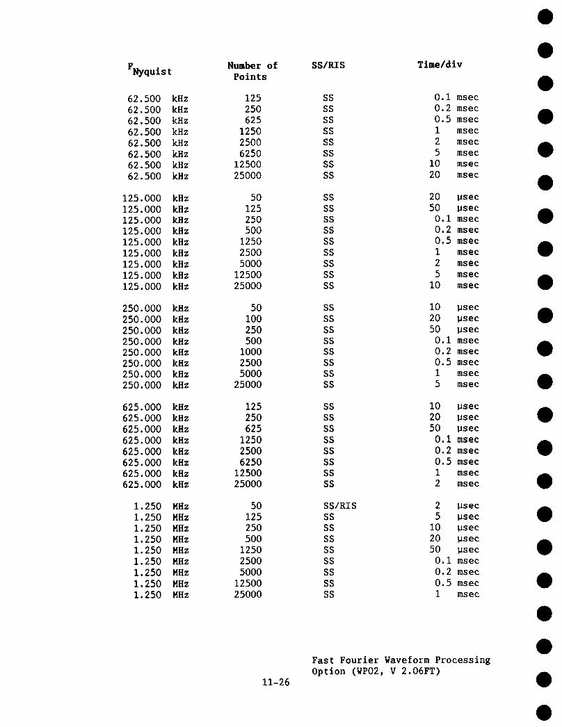
FNyquist
62.500 kHz62.500 kHz62.500 kHz62.500 kHz62.500 kHz62.500 kHz62.500 kHz62.500 kHz
125.000 kHz125.000 kHz125.000 kHz125.000 kHz125.000 kHz125.000 kHz125.000 kHz125.000 kHz125.000 kHz
250.000 kHz250.000 kHz250.000 kHz250.000 kHz250.000 kHz250.000 kHz250.000 kHz250.000 kHz
625.000 kHz625.000 kHz625.000 kHz625.000 kHz625.000 kHz625.000 kHz625.000 kHz625.000 kHz
1.250 MHz1.250 MHz1.250 MHz1.250 MHz1.250 MHz1.250 MHz1.250 MHz1.250 MHz1.250 MHz
Number ofPoints
12525O625
125025006250
1250025000
50125250500
125025005000
1250025000
50i00250500
I00025005000
25000
125250625
125025006250
1250025000
50125250500
125025005000
1250025000
SS/RIS Time/div
SS 0.I msecSS 0.2 msecSS 0.5 msecSS 1 msecSS 2 msecSS 5 msecSS I0 msecSS 20 msec
SS 20 gsec
SS 50 gsec
SS 0.I msecSS 0.2 msecSS 0.5 msecSS i msecSS 2 msecSS 5 msecSS I0 msec
SS I0 ~secSS 20 BsecSS 50 BsecSS 0.i msecSS 0.2 msec
SS 0.5 msecSS 1 msecSS 5 msec
SS I0 usecSS 20 ~secSS 50 ~secSS 0.i msecSS 0.2 msecSS 0.5 msecSS i msecSS 2 msec
SS/RIS 2 ~secSS 5 psec
SS I0 usecSS 20 ~secSS 50 psecSS 0.I msecSS 0.2 msecSS 0.5 msecSS I msec
11-26
Fast Fourier Waveform ProcessingOption (WP02, V 2.06FT)

FNyquist
2.500 MHz2.500 MHz2.500 MHz2.500 MHz2.500 MHz2.500 MHz2.500 MHz2.500 MHz
6.250 MHz6.250 MHz6.250 MHz6.250 MHz6.250 MHz6.250 MHz6.250 MHz6.250 MHz
12.500 MHz12.500 MHz12.500 MHz12.500 MHz12.500 MHz12.500 MHz12.500 MHz12.500 MHz12.500 MHz
25.000 MHz25.000 MHz25.000 MHz25.000 MHz25.000 MHz25.000 MHz25.000 MHz25.000 MHz
50.000 MHz50.000 MHz50.000 MHz50.000 MHz50.000 MHz50.000 MHz50.000 MHz50.000 MHz50.000 MHz
Number ofPoints
5Oi0025050O
100025005000
25000
125250625
125025006250
1250025000
5O1252505OO
125025005000
1250025000
5Oi0025O5OO
i00025005OOO
25000
5OI002005OO
i00020005000
i000020000
SS/RIS
SS/RISSS/RISSSSSSSSSSSSS
SS/RISSS/RISSSSSSSSSSSSS
SS/RISSS/RISSS/RISSS/RISSSSSSSSSSS
SS/RISSS/RISSS/RISSS/RISSS/RISSSSSSS
SS/RISSS/RISSS/RISSS/RISSS/RISSSSSSSSS
Time/div
i ~sec2 ~see5 Bsec
I0 ~sec20 ~sec50 ~sec
0.I msec0.5 msec
1 ~sec2 ~sec5 ~sec
I0 ~sec20 ~sec50 usec
0.i msec0.2 msec
0.2 ~sec0.5 msec1 ~sec2 ~sec5 ~sec
I0 ~sec20 ~sec50 ~sec
0.I msec
0.I ~sec0.2 ~sec0.5 ~sec1 ~sec2 ~sec5 usec
I0 usec50 psec
50 nsec0.I usec0.2 ~sec0.5 ~sec1 ~sec2 ~sec5 ~sec
I0 ~sec20 ~sec
11-27
Fast FourierOption (WP02,
Waveform ProcessingV 2.06FT)

FNyqui s t
125.000 HHz125.000 MHz125.000 MHz125.000 HHz125.000 HHz125.000 HHz125.000 HHz
250.000 MHz250.000 HHz250.000 HHz250.000 MHz250.000 MHz250.000 MHz250.000 MHz
625.000 MHz625.000 HHz625.000 HHz625.000 MHz625.000 MHz625.000 HHz625.000 MHz625.000 HHz
1250.000 MHz1250.000 MHz1250.000 MHz1250.000 MHz1250.000 HHz1250.O00 MHz1250.000 HHz1250.000 MHz1250.000 MHz
2500.000 MHz2500.000 MHz2500.000 MHz2500.000 MHz2500.000 HHz2500.000 MHz2500.000 MHz
Number ofPoints
5O12525O5OO
125025005000
50I00250500
i00025005000
125250625
125025006250
1250025000
5O1252505OO
125025005000
1250025000
i002505OO
100025005000
25000
SS/RIS
RISRISRISRISRISRISRIS
RISRISRISRISRISRISRIS
RISRISRISRISRISRISRISRIS
RISRISRISRISRISRISRISRISRIS
RISRISRISRISRISRISRIS
Time/div
20 nsec50 nsec
0.1 gsec0.2 psec0.5 ~sec1 gsec2 gsec
10 nsec20 nsec50 nsec
0.1 gsec0.2 gsec0.5 gsec1 ~sec
10 nsec20 nsec50 nsec
0.1 psec0.2 Bsec0.5 psec1 ~sec2 ~sec
2 nsec5 nsec
I0 nsec20 nsec50 nsec
0.i ~sec0.2 ~sec0.5 psec1 ~sec
2 nsec5 nsec
10 nsec20 nsec50 nsec
0.I ~sec0.5 ~sec
11-28
Fast FourierOption (WPO2,
Waveform ProcessingV 2.06FT)

11.9 References
Bergland, G. D., "A Guided Tour of the Fast Fourier Transform", IEEESpectrum, July 1969, pp. 41 - 52.
A general introduction to FFT theory and applications.
Harris, F. J., "On the Use of Windows for Harmonic Analysis with theDiscrete Fourier Transform", Proceedings of the IEEE, vol 66, No I,January 1978, pp. 51 - 83.
Classical paper on window functions and their figures of merit, withmany examples of windows.
Brigham, E.O., "The Fast Fourier Transform", Prentice Hall, Inc.,Englewood Cliffs, N. J., 1974.
Theory, applications and implementation of FFT. Includes discussion ofFFT algorithms for N not a power of 2.
Ramirez, R, W., "The FFT Fundamentals and Concepts", Prentice Hall,Inc., Englewood Cliffs, N. J., 1985.
Practice oriented, many examples of applications.
11-29
Fast Fourier Waveform ProcessingOption (WP02, V 2.06FT)

11.10 Index of Topics
Paragraph
11.611.611.611.5.211.5.211.5.211.5.311.4.211.4.111.611.711.511.4.111.311.5.111.5.211.611.611.611.611.611.611.211.611.611.811.611.611.6ii.i11.911.611.611.611.6
Topic
AliasingCoefficients of window functions in tabular formCoherent gainComputation of dBm power spectrumComputation of magnitudeComputation of real/imaginary partsComputation speed of FFTDescription of additional values of FFT descriptorsDescription of remote FFT commandsEquivalent Noise Bandwidth (ENBW)Error and warning messagesFFT processing, application hintsFFT processing, description of remote control commandsFFT processing, examplesFFT processing, practical rules for using FFT processingFFT processing, steps involved in calculating the FFTFFT/940OA GlossaryFiltersFrequency binsFrequency rangeFrequency resolutionLeakageModification to WPOI functionsNumber of points used for computing the FFTNyquist frequencyNyquist frequency tablePicket fence effectPower spectrumPower density spectrumProcessing capabilities of FFT optionReferencesSampling frequencyScallop lossWindow frequency domain parameters in tabular formWindow functions
11-30
Fast Fourier Waveform ProcessingOption (WP02, V 2.06FT)
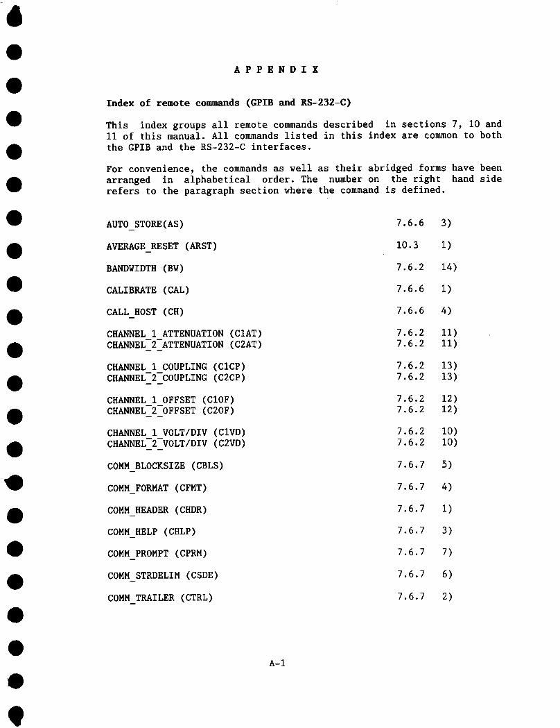
APPENDIX
Index of remote commands (GPIB and RS-232-C)
This index groups all remote commands described in sections 7, I0 andII of this manual. All commands listed in this index are common to boththe GPIB and the RS-232-C interfaces.
For convenience, the commands as well as their abridged forms have beenarranged in alphabetical order. The number on the right hand siderefers to the paragraph section where the command is defined.
AUTO_STORE(AS)
AVERAGE RESET (ARST)
BANDWIDTH (BW)
CALIBRATE (CAL)
CALL HOST (CH)
CHANNEL1 ATTENUATION (CIAT)CHANNEL2 ATTENUATION (C2AT)
CHANNEL1 COUPLING (CICP)CHANNEL2 COUPLING (C2CP)
CHANNELI OFFSET (CIOF)CHANNEL2 OFFSET (C20F)
CHANNEL 1 VOLT/DIV (CIVD)CHANNEL 2 VOLT/DIV (C2VD)
COMMBLOCKSIZE (CBLS)
COMMFORMAT (CFMT)
COMMHEADER (CHDR)
COMM HELP (CHLP)
COMMPROMPT (CPRM)
COMMSTRDELIM (CSDE)
COMMTRAILER (CTRL)
7.6.6 3)
10.3 i)
7.6.2 14)
7.6.6 1)
7.6.6 4)
7.6.2 Ii)7.6.2 Ii)
7.6.2 13)7.6.2 13)
7.6.2 12)7.6.2 12)
7.6.2 I0)7.6.2 I0)
7.6.7 5)
7.6.7 4)
7.6.7 I)
7.6.7 3)
7.6.7 7)
7.6.7 6)
7.6.7 2)
A-1
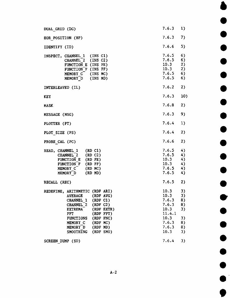
DUAL GRID (DG)
HOR POSITION (HP)
IDENTIFY (ID)
INSPECT, CHANNEL 1 (INS Cl)CHANNEL--2 (INS C2)FUNCTION E (INS FE)FUNCTION-F (INS FF)MEMORY C- (INS MC)MEMORY-D (INS MD)
INTERLEAVED (IL)
KEY
MASK
MESSAGE (MSG)
PLOTTER (PT)
PLOT SIZE (PS)
PROBE CAL (PC)
READ, CHANNEL 1 (RD Cl)CHANNEL-2 (RD C2)FUNCTION E (RD FE)FUNCTION-F (RD FF)MEMORY C- (RD MC)MEMORY-D (RD MD)
RECALL (REC)
REDEFINE, ARITHMETIC (RDF ARI)AVERAGE (RDF AVG)CHANNEL 1 (RDF CI)CHANNEL 2 (RDF C2)EXTREMA (RDF EXTR)FFT (RDF FFT)FUNCTIONS (RDF FNC)MEMORY C (RDF MC)MEMORY-D (ROE MD)SMOOTHING (ROE SMO)
SCREEN DUMP (SD)
A-2
7.6.3
7.6.3
7.6.6
7.6.57.6.510.310.37.6.57.6.5
7.6.2
7.6.3
7.6.8
7.6.3
7.6.4
7.6.4
7.6.6
7.6.57.6.510.310.37.6.57.6.5
7.6.5
10.310.37.6.37.6.310.311.4.110.37.6.37.6.310.3
7.6.4
1)
7)
5)
6)6)2)2)6)6)
2)
I0)
9)
1)
2)
4)4)4)4)4)4)
2)
3)3)8)8)3)
3)8)8)3)
3)

SEGMENTS (SEG)
SELECT (SEL)
SETUP (SU)
STB
STOP
STORE (STO)
TIME/DIV (TD)
TIME MAGNIFIER (TM)
TRACE CHANNEL 1TRACE-CHANNEL-2TRACE-EXPANDTRACE-EXPAND-BTRACE-MEMORY-CTRACE-MEMORY-D
(TRCI)(TRC2)(TREA)(TREB)(TRMC)(TRMD)
TRACE-FUNCTION E (TRFE)TRACE-FUNCTION-F (TRFF)
TRANSMIT (TX)
TRIG COUPLING (TRC)
TRIG DELAY (TRD)
TRIG LEVEL (TRL)
TRIG MODE (TRM)
TRIG SLOPE (TRP)
TRIG SOURCE (TRS)
TSTB
VERT GAIN (VG)
VERT POSITION (VP)
WAIT
WRITE, MEMORY CMEMORY-D
(WT,MC)(WT,MD)
7.6.2
7.6.3
7.6.5
7.6.8
7.6.2
7.6.5
7.6.2
7.6.3
7.6.37.6.37.6.37.6.37.6.37.6.37.6.37.6.3
7.6.4
7.6.2
7.6.2
7.6.2
7.6.2
7.6.2
7.6.2
7.6.8
7.6.3
7.6.3
7.6.6
7.6.57.6.5
9)
3)
3)
I)
15)
1)
i)
6)
2)2)2)2)2)2)2)2)
4)
5)
3)
4)
6)
8)
7)
3)
4)
5)
6)
5)5)
A-3

Additional RS-232-C only remote commands
This subsection contains only those remote commands which are specificto RS-232-C communication.
<ESC> < 7.6.10 7)
<ESC> L 7.6.10 I0)
<ESC> ( 7.6.10 3)
<ESC> ) 7.6.10 4)
<ESC> C 7.6.10 II)
<ESC> R 7.6.10 9)
<ESC> T 7.6.10 12)
<ESC> [ 7.6.10 5)
<ESC> ] 7.6.10 6)
RS CONF 7.6.10 I)
RS SRQ 7.6.10 2)n
A-4