oncilla robot: a versatile open-source quadruped research ... · with oncilla robot we extend the...
TRANSCRIPT

Oncilla robot: a versatile open-sourcequadruped research robot with compliantpantograph legsAlexander Sprowitz 1,2,∗, Alexandre Tuleu 1, Mostafa Ajallooeian 1, MassimoVespignani 1, Rico Mockel 1,3, Peter Eckert 1, Michiel D’Haene 4, JonasDegrave 4, Arne Nordmann 5, Benjamin Schrauwen 4, Jochen Steil 5, and AukeJan Ijspeert 1
1Biorobotics Laboratory, Institute of Bioengineering, Ecole polytechnique federale deLausanne (EPFL), Lausanne, Switzerland2Dynamic Locomotion Group, Max Planck Institute for Intelligent Systems, Stuttgart,Germany3Department of Knowledge Engineering, Maastricht University, The Netherlands4Department of Electronics and Information Systems, Ghent University, Gent,Belgium5CoR-Lab, Research Institute for Cognition and Robotics, Bielefeld University,GermanyCorrespondence*:Heisenbergstr. 3, 70569 [email protected]
ABSTRACT
We present Oncilla robot, a novel mobile, quadruped legged locomotion machine. This large-catsized, 5.1 kg robot is one of a kind of a recent, bioinspired legged robot class designed with thecapability of model-free locomotion control. Animal legged locomotion in rough terrain is clearlyshaped by sensor feedback systems. Results with Oncilla robot show that agile and versatilelocomotion is possible without sensory signals to some extend, and tracking becomes robustwhen feedback control is added (Ajallooeian, 2015b). By incorporating mechanical and controlblueprints inspired from animals, and by observing the resulting robot locomotion characteristics,we aim to understand the contribution of individual components. Legged robots have a widemechanical and control design parameter space, and a unique potential as research tools toinvestigate principles of biomechanics and legged locomotion control. But the hardware andcontroller design can be a steep initial hurdle for academic research. To facilitate the easy startand development of legged robots, Oncilla-robot’s blueprints are available through open-source.
The robot’s locomotion capabilities are shown in several scenarios. Specifically, its spring-loadedpantographic leg design compensates for overdetermined body and leg postures, i.e. duringturning maneuvers, locomotion outdoors, or while going up and down slopes. The robot’s activedegree of freedom allow tight and swift direction changes, and turns on the spot. Presentedhardware experiments are conducted in an open-loop manner, with little control and computational
1
arX
iv:1
803.
0625
9v2
[cs
.RO
] 1
6 Ju
n 20
18

Sprowitz et al. Oncilla robot
effort. For more versatile locomotion control, Oncilla-robot can sense leg joint rotations, and leg-trunk forces. Additional sensors can be included for feedback control with an open communicationprotocol interface. The robot’s customized actuators are designed for robust actuation, andefficient locomotion. It trots with a cost of transport of 3.2 J/(Nm), at a speed of 0.63 m s−1 (Froudenumber 0.25). The robot trots inclined slopes up to 10, at 0.25 m s−1. The multi-body Webotsmodel of Oncilla robot, and Oncilla robot’s extensive software architecture enables users todesign and test scenarios in simulation. Controllers can directly be transferred to the real robot.Oncilla robot’s blueprints are open-source published (hardware GLP v3, software LGPL v3).
Keywords: quadruped, robot, pantograph, open-source, multiple gaits, open-loop, pattern generator, turning
1 INTRODUCTION
Emerging technologies allow to improve our understanding of legged locomotion, and its underlyingprinciples. We argue that custom-designed, bioinspired legged machines like the presented Oncilla robothave the potential to provide valuable insights into biomechanics and neuromuscular control of animallegged locomotion. We show initial robot locomotion examples in simulation and hardware, directed withminimal control effort.
Technological progress shapes research, for instance traditional dissection tools are being expanded bycomputer guided imaging. 3D scans provide spatial data of the animal’s morphology even in motion (Walkeret al., 2014). Advanced computer simulations give insights into complex interactions between muscles,tendons, and skeletal structures during locomotion (Delp et al., 2007). This allows estimating movements,forces and interactions of otherwise hidden and unaccessible structures in animals. With the help of newtechnologies, it is the goal to find necessary and sufficient biomechanical and neuromuscular controlcomponents for legged locomotion, by identifying form and function.
However, mapping morphologies to function is not trivial. Evolutionary byproducts such as spandrelscan mask function of structures (Gould and Lewontin, 1979). The animal legged apparatus developed forlocomotion—a complex task with hybrid dynamics. Balancing, carrying and accelerating the animal’s bodyrequires precise movement coordination through feedback, and redirection of loads. Forces and movementslargely differ in swing and stance phase, separated by harsh impacts at landing, and high velocities duringtoe off (Sohnela et al., 2017).
Our approach includes custom-made, bioinspired legged robot hardware, and its locomotion controller.Oncilla robot allows us to tackle locomotion research from a new perspective, and directly evaluatefunctional morphologies. With robotic setups we have the freedom to implement and test simplified‘blueprints’, mimicking aspects of animals’ biomechanics and neuromuscular control. We understand such‘blueprints’ as building plans which are transferred from Biology to Robotics, for the purpose of testingand characterizing them. The pantographic leg configuration described by ? is an example for a mechanicalblueprint, that was transferred from animal biomechanics. It is based on the observation of the mostlyparallel orientation of distal and proximal limb segments in three-segmented mammalian legs, duringlocomotion. Mathematical models of the spinal cord activation i.e. in lampreys, so called ’Central PatternGenerators’, are an example for a neuromuscular control blueprint. They were hypothesized and observedin animals, and tested and implemented in robots (?).
Robotic implementations can swiftly be altered, i.e. to test effects of scaling, while longitudinal animalstudies are significantly more time consuming. Testing features in robot hardware allows one to quantify
This is a provisional file, not the final typeset article 2

Sprowitz et al. Oncilla robot
function; components’ states (position, velocity etc.), forces linking components, and internal loads canbe measured with dedicated sensors. Signals for locomotion control and sensing are observable, andmostly controlled. In contrast, recording of deep tissue movements and displacements, and their interactingforces in animals is often not feasible. At present recording of animal nerve signals is limited to simplersetups (Daley et al., 2009).
Computer simulated models of legged animals and legged robots forcibly introduce simplifications,compared to real world physics. Several aspects of physics are notably hard to simulate both precisely andefficiently: leg-ground impacts, wobbling masses, damping, compliance and friction (Schmitt and Gunther,2011). Correctly simulating a legged animal or robot walking through soft substrate is difficult (Falkinghamand Gatesy, 2014; Li et al., 2009). In comparison, robotic hardware can be a realistic physical (as opposedto numerical) model of an animal—legs and feet are physically interacting with locomotion substratesthrough contact forces. Still, computer models are immensely insightful, also because they are relativelyeasy to derive and apply. Here, we derived a computer simulated Oncilla robot model to rapidly testcontroller parameters, and create locomotion data.
A future iterative robotic approach to legged research can be composed of four steps: a) implementingblueprints of mechanics and control of legged animals, in a legged robot system, b) creating locomotion casescenarios with legged robots, c) collecting and analyzing locomotion data, and eventually d) implementingalterations to initial blueprints. If successful, improved blueprints will decrease the discrepancy betweenrobot and animal locomotion characteristics. Changes and observed invariants allow insights into underlyingaspects of legged locomotion.
From a design and testing perspective, the cyclic iteration works best if tested blueprints can be alteredswiftly. Oncilla robot is designed modularly, i.e. its legs and trunk, actuators, sensors, and controllers arerelatively easy to replace. Research in legged locomotion progresses iteratively, and fewer researchers areinterested in designing entire robotic systems. The Oncilla robot open source project allows researchers toi.e. test sub-functions of a new locomotion controller. Reproducing parts requires a low level of technology;access to a generic 3D printer, and a basic machining workshop. Components such as brushless motors areoff-the-shelve items. Printed circuit board layouts and firmware code are included in the project sourcecode. If required, they can be replaced by custom solutions—Oncilla robot’s custom interfaces are opensourced.
A novice user requires a legged robot that is easy to start up and run. A robot with a large basin ofrobust locomotion patterns is therefore beneficial. Ideally, the robot’s locomotion characteristic would besufficiently ’docile’. At the same time, the robot should have the potential for complex gait scenarios, suchas rapid acceleration, turning, and locomotion on slopes.
Oncilla robot features a spring-loaded leg design enabling simplified locomotion control. As a conse-quence, this class of legged robots including ’Bow-leg robot’, ’Cheetah-cub robot’, Bobcat-robot’, and‘Ken’ (Sprowitz et al., 2013; Zeglin, 1999; Khoramshahi et al., 2013; Narioka et al., 2012) can run andhop with feed-forward (FFW) control and does not require model-based control or feedback mechanisms,for basic locomotion on flat terrain. These robots run in FFW mode at comparatively low control frequen-cies: Sprowitz et al. (2013) report RC servo motor control with as little as f = 50 Hz control frequency,also in case of step-down perturbations during higher speed running.
In comparison, robots with leg designs like MIT Cheetah (Seok et al., 2013) or ANYmal (Hutter et al.,2016) actively extend leg joints against gravity. Actively extending legs require dedicated controllers forleg length force control (Hyun et al., 2014).
Frontiers 3

Sprowitz et al. Oncilla robot
With Oncilla robot we extend the capabilities of its robot class with its passively, spring extending legs;the robot turns rapidly, with minimal turning radii, walks slopes up and down, and outdoors on naturalsubstrates fully mobile, with low computational effort and without the need for sensory feedback.
The remaining paper is organized as follows. In the next section, we briefly present related work. Section 2describes the robot’s mechanical hardware. Section 3 explains the software architecture of Oncilla robot.Results from hardware and simulation experiments are shown in Section 4. We discuss design, results andfuture directions and provide links to the open-source files in Section 5, and conclude in Section 6. Thesupplementary material provides further details on robot design, kinematics, and experiments.
2 MECHANICAL HARDWARE
This section explains Oncilla robot’s design, and its actuator design process. Details are provided for itsleg design, the active degree of freedom (DOF) for steering, force sensors, chassis design, and electroniccircuits.
2.1 Physical robot dimensions
Oncilla robot has the size and weight of a large house cat (Table 1). It is 0.4 m long in total, with 0.23 mbetween front and hind legs, has a maximal hip height of 0.18 m with its legs hanging in-air, a hip standingheight of 0.16 m, and an overall height of 0.31 m, from bottom to handle (Figs. 1 and 2). The robot has0.14 m of lateral spacing between left and right adduction/abduction axes, and a maximum width of 0.25 m.Total weight is 4.5 kg without, and 5.1 kg with a 4500 mAh lithium polymer battery pack. The trunk wasdesigned with a center of mass (COM) 36 mm below the hip-shoulder axis. Each leg weighs 0.2 kg without,and 0.6 kg including leg angle and leg length actuators.
2.2 Actuator design
Choosing a robust actuator consisting of motor and gearbox is not trivial, when designing robots for agilelegged locomotion. Here we only considered electromagnetic motors, for their ease of use in laboratories.
Mobile robots carry their own weight. This includes the power source, i.e. in form of batteries, but alsoprinted circuit boards (PCB), actuators, chassis, and sensors. To reduce power consumption and to increaseagility and load carrying capability, low weight and efficient actuators are beneficial. At least two DOFper leg are required for versatile legged locomotion. The leg length (LL) DOF inserts forces to maintainvertical posture. This LL DOF is also used for leg flexion during swing phase. The sagittal leg angle (LA)DOF supports movements and torques in fore-aft direction, and retracts and protracts the leg. Leggedrobot locomotion is a harsh application for electrical motors. Oscillating locomotion patterns at high cyclefrequencies lead to high velocities in both directions and at high peak torques. Those present ‘externalloads’. Motor and gearbox combinations lead to additional ’internal loads’, and can largely exceed external,required loads (Roos et al., 2006). This effect showed strongly with Cheetah-cub robot, a small quadrupedrobot actuated by high-geared RC servo motors. RC servo motors would work well for 1 Hz motionfrequencies. However at 4 Hz motion frequencies and larger amplitudes, the over 300 : 1 gearbox ratioled to overheating problems. Only brief experiments with cool-down phases were possible in a repeatablemanner (Sprowitz et al., 2013).
To improve actuation compared to Cheetah-cub robot, we simulated external load case scenarios forLL and LA actuator, based on a simplified foot locus. We assumed cycle frequencies between 0.5 Hzand 3.5 Hz, calculated for a trotting quadruped with Oncilla robot’s dimensions. This external load case
This is a provisional file, not the final typeset article 4

Sprowitz et al. Oncilla robot
data was piped through an actuator optimization framework (Roos et al., 2006), creating a simplified-loaddynamical motor model. From this, we chose gearbox ratios in LL (56 : 1) and LA (84 : 1) direction, fora given brushless motor. Details for the external and internal load case simulation setup are provided insupplementary documentation. With an estimated 80 % effective stride length, the modeled robot’s cost oftransport was calculated (Tucker, 1970). Results are shown in Fig. 7. The model predicts an asymptoticallydeclining COT, with 7.8 J/(Nm) at a low speed of 0.05 m s−1, a lowest COT of 2.4 J/(Nm) at 0.41 m s−1,and a slightly increasing COT at higher speeds (2.7 J/(Nm) at 0.71 m s−1). We later recorded the hardwarerobot’s instantaneous power during locomotion, which shows a good match. While underestimating thehardware COT by about 25 %, the simplified-load model did qualitatively predict the asymptoticallydeclining COT characteristics of the hardware robot.
2.3 Leg and foot design
Oncilla robot’s leg design is a continuation of Cheetah-cub robot’s. One active DOF was added foradduction/abduction (’AA joint’), to give the robot steering capabilities. A set of springs with stiffness5.8 N/mm extends the pantograph leg (red ’diagonal spring’, Fig. 3). One pantograph-segment is replacedwith a tensile spring (blue ’parallel spring’, stiffness k = 7.4 N/mm). This spring allows flexion of thedistal leg segment under load. The leg extends by 7 cm, from its shortest length i.e. during mid-swing, toa fully extended leg length of 18 cm in air. A short foot is mounted, spring tensioned by a torsion spring(k = 1.21 Nmm/). Absolute position encoders are placed at hip axes, and two leg joints (supplementarymaterial, Fig. S7, q0, q1, q2). The difference between angles q1 and q2 indicates the external load torqueacting at q2, i.e. this joint sensor also acts as analog contact sensor.
2.4 Leg length and leg angle actuation
The robot was designed with mechanical improvements in mind compared to Cheetah-cub robot: in-creasing load carrying capabilities, incorporating an additional DOF per leg for efficient and fast turning,adding multiple modes of sensing, and adding batteries and on-board power for mobile application. Eachadditional feature increased the weight, from a 1.1 kg Cheetah-cub robot to a 5.1 kg Oncilla robot. ForOncilla robot’s larger weight, a stiffer leg spring was mounted, which in turn required a higher-torqueactuator for the leg flexing mechanism. The LL actuator is mounted serially to the leg angle actuator, andshortens the leg through a cable (Fig. 3). This design has positive consequences: a) The LL actuator isdecoupled from external forces, such as sudden impacts. Hence, the mounted gearbox requires a lowersafety rating, and can be designed with a lower module gear design. b) During stance phase, parallel legsprings act passively, i.e. the design is a close approximation of the mechanism underlying the springloaded inverted pendulum (Blickhan, 1989, SLIP template). The sagittal leg angle actuator is directlyattached to the proximal leg segment. The motor’s long and narrow shape blocked mounting left and rightleg motors in line. Instead we applied a non-symmetrical actuator placement, with legs relatively close toeach other (0.14 m, Fig. 2 and Fig. S6). The short distance leads to a short moment arm i.e. for diagonallytouching legs, and is meant to reduce rolling motions. Leg angle motor and hip axis are connected bya large module spur gear (Fig. 2). Relative encoders are directly mounted to both brushless motor axes.One absolute encoder is mounted at the main LA axis. Incremental motor encoders support precise motorcontrol, and absolute encoders read leg segment positions, and leg spring loading.
2.5 Hip adduction and abduction joint
The added hip adduction and abduction (AA) actuation was installed for efficient turning. The chosenAA actuator is a strong, position controlled RC servo motor (Kondo KRS 2350 ICS). It was selected for its
Frontiers 5

Sprowitz et al. Oncilla robot
compact design, high holding torque, and standardized control interface. The servo horn connects througha four bar mechanism with the leg, with a movement range of ±8 (Fig. 2).
2.6 Force sensors
Custom-made, two-axis force sensors were implemented proximally, within the AA suspension betweentrunk and legs ( 8 , Fig. 1). Force sensors were designed based on double cantilever bending beams, withfoil strain sensing resistors in full bridge configuration. Sensors measure forces in vertical and fore-aftdirection, in the trunk’s coordinate system. Oncilla robot’s force sensors were not utilized for the gaitsshown in this work. Instead, all gaits shown are generated in feed-forward mode. Force sensing is howevernecessary for either model-based control based on leg loading information, or non-model based controllerswith i.e. reflex-like feedback (?). Because similar locomotion experiments are planned with Oncilla robot,custom designed force sensors are included here.
We considered two mounting places: distally, i.e. as feet, or proximally, between the robot’s trunk andlegs, as finally chosen. When mounting force sensors distally, almost no effects from unsprung masses aremeasured, but direct contacts between leg and ground. Consequently, the resulting force signal requires lessnoise filtering. However, distally and foot-mounted sensors rotate with the foot frame. In case the directionof force is of interest for control, the sensor’s orientation should be recalculated through the serial chain oftrunk, leg segments, and foot sensor. Mechanically, a distal sensor placement moves the leg’s center ofmass further distally, especially for larger and more complex sensors. It also limits mounting spring-loadedfeet. To cope with harsh touch down impacts, a miniaturized but also robust sensor design is required.
In comparison, proximal force sensor mounts are relatively independent from leg and foot design. In ourcase sufficient mounting space was available proximally. Standard-sized, strain gage-based sensors werechosen and implemented. Drawbacks exists; proximally sensed force signals are influenced by mass andinertia of the moving leg, and data post-processing is required. Latter will introduce sensor signal delays.Such delays can present an obstacle especially for fast loop locomotion controllers. Proximal force sensorsrequire no recalculation of the sensor’s orientation, as they are fixed in the trunk frame.
2.7 Electronics and PCB mounting
Oncilla robot carries its actuators and sensors, a battery pack, and PCBs for motor control, power supply,and communication. Brushless motor driver boards were custom designed, and each of four boards providescontrol and power for two brushless motors. One board weighs 0.15 kg, and all are mounted low, at therobot’s geometric center. This placement helps keeping the robot’s COM below the virtual hip-shoulderaxis—the robot’s trunk ’hangs’ in-between. The remaining PCBs are placed at the front of the robot(RB-110, main computing and communication), and at the rear end (power supply), for easy access. Aninertia measurement unit (MicroStrain 3DM-GX3-35 IMU) is mounted above the motor driver boards.Further details on the electronic layout, components, operation system are available in the supplementarymaterial (i.e. Fig. S9).
3 SOFTWARE
In this section we describe software related concepts developed for the Oncilla robot; namely the communi-cation bus connecting main control boards and periphery, the motor controller, Oncilla robot’s softwarearchitecture, and the simulated Oncilla robot model in Webots.
This is a provisional file, not the final typeset article 6

Sprowitz et al. Oncilla robot
3.1 Communication layer and protocol
Communication between main electronic modules is performed over a RS-485 physical layer, organizedin a master/slave point-to-multipoint half-duplex configuration (Fig. 4). The data link and network layeron the bus is implemented through a custom Simple Binary Communication Protocol (SBCP). Latterimplementation is an extension of the Bioloid Dynamixel Communication Protocol version 1 (Dynamixel,2006). The main modification is the change of the two byte packet preamble (value 0xFFFF). This preamblewas separated; one single byte preamble (0XFF), and a ClassID byte to designate the device type we wantto address, i.e. the motor driver board, power board, or master control board. By reserving the class valuefor Bioloid devices, Oncilla robot’s hardware and driver are capable of directly incorporating these.
A major challenge in the SBCP design was the high communication bandwidth requirement. We initiallyaimed at a 1 kHz control loop on the embedded computer level, this translates to a RS-485 baud rateof 3.3 Mbps. Recently such high speed UARTs became available in embedded computers (< 12 Mbpsat the moment), through an USB to serial Integrated Circuit (IC). However, USB bus communicationis scheduled by 1 ms frame sizes, and a naive bus implementation would be limited to reach a deviceevery 2 ms. Instead, we implemented a bus control data flow in a dedicated device (SBCP master board)controlled by a dsPIC33FJ128MC802 Digital Signal Processor (DSP), mounted after the USB to serialIC. This SBCP master board is able to: a) Handle a group of up to 8 combined packets sent over a fullduplex UART connection. b) Manage communication over the half duplex RS-485 bus with a latency of12 µs and maximal jitter of 2.2 µs. c) Detect slave timeouts and react accordingly with user customizabledelays. To reduce jitter and latency to a minimum, we utilized many optimization features of the dsPIC33FJprocessor family such as Direct Memory Access (DMA), reduction of interruption stress on the processor,and anticipated packet precomputation and pre-buffering to reduce latency between packet responses. Allimplementation details are abstracted by a reusable library, SBCP-uc 4. This new open source libraryenables fast development of slave device SBCP interfaces for this processor family.
3.2 Motor control
The custom designed motor driver boards implement a Proportional-Integral-Derivative (PID) controllerfor two brushless motors on a dsPIC33JF128MC804 DSP. It controls two A3930 motor driver ICs which areused to drive a three phase inverter made of six IRFR48Z MOSFETs. These ICs are able to limit the motorwinding current. DSP PID controller parameters were hand tuned. In order to reduce motor jitter duringposition tracking, a velocity profile interpolation is implemented on the motor driver DSPs. The user setsthe desired tracking frequency, and the tracking velocity is then computed on-board. Initially we observedtrajectory tracking losses every several seconds. We found the cause in a combination of communicationjitter and real-time clock frequency mismatch. Tested RB-110 boards had crystal frequency deviations ofup to +0.3 %, from their standard frequency. As a workaround, we implemented precise buffering andreal-time clock re-synchronization heuristics on the motor driver DSP. The maximum tracking frequency is500 Hz, half of the DSP internal control loop (1 kHz).
3.3 Software Architecture
The software architecture of Oncilla robot is based on two primary design decisions tied to the re-quirements of open research projects (Nordmann et al., 2013): a) It provides a common interface for thesimulator and for the hardware. This allows for easy and fast transition of experiments between simulationand real-world experiments. b) It provides a local interface for fast control loops running on the embeddedPC, as well as a remote interface to allow more complex applications to control the robot over the network.
Frontiers 7
Sprowitz et al. Oncilla robot
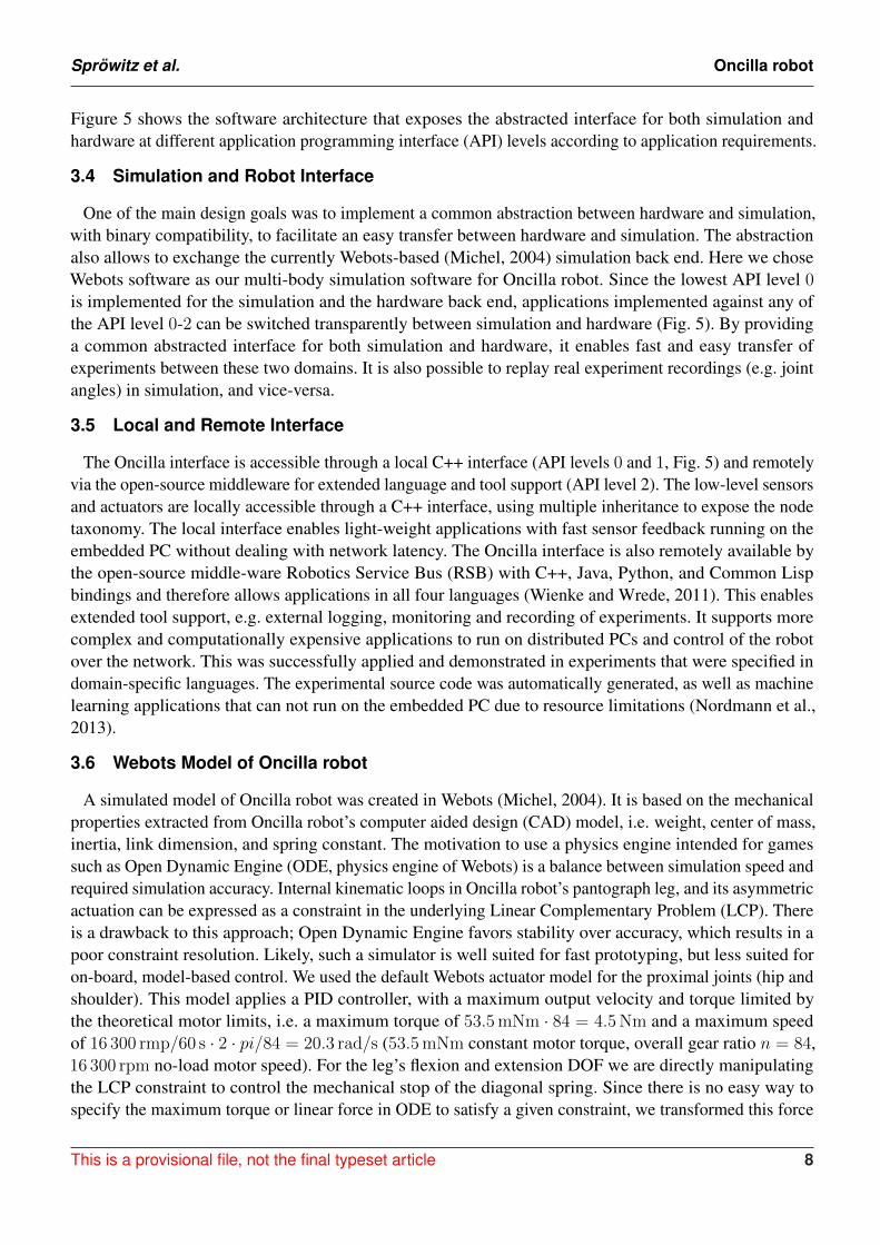
Figure 5 shows the software architecture that exposes the abstracted interface for both simulation andhardware at different application programming interface (API) levels according to application requirements.
3.4 Simulation and Robot Interface
One of the main design goals was to implement a common abstraction between hardware and simulation,with binary compatibility, to facilitate an easy transfer between hardware and simulation. The abstractionalso allows to exchange the currently Webots-based (Michel, 2004) simulation back end. Here we choseWebots software as our multi-body simulation software for Oncilla robot. Since the lowest API level 0is implemented for the simulation and the hardware back end, applications implemented against any ofthe API level 0-2 can be switched transparently between simulation and hardware (Fig. 5). By providinga common abstracted interface for both simulation and hardware, it enables fast and easy transfer ofexperiments between these two domains. It is also possible to replay real experiment recordings (e.g. jointangles) in simulation, and vice-versa.
3.5 Local and Remote Interface
The Oncilla interface is accessible through a local C++ interface (API levels 0 and 1, Fig. 5) and remotelyvia the open-source middleware for extended language and tool support (API level 2). The low-level sensorsand actuators are locally accessible through a C++ interface, using multiple inheritance to expose the nodetaxonomy. The local interface enables light-weight applications with fast sensor feedback running on theembedded PC without dealing with network latency. The Oncilla interface is also remotely available bythe open-source middle-ware Robotics Service Bus (RSB) with C++, Java, Python, and Common Lispbindings and therefore allows applications in all four languages (Wienke and Wrede, 2011). This enablesextended tool support, e.g. external logging, monitoring and recording of experiments. It supports morecomplex and computationally expensive applications to run on distributed PCs and control of the robotover the network. This was successfully applied and demonstrated in experiments that were specified indomain-specific languages. The experimental source code was automatically generated, as well as machinelearning applications that can not run on the embedded PC due to resource limitations (Nordmann et al.,2013).
3.6 Webots Model of Oncilla robot
A simulated model of Oncilla robot was created in Webots (Michel, 2004). It is based on the mechanicalproperties extracted from Oncilla robot’s computer aided design (CAD) model, i.e. weight, center of mass,inertia, link dimension, and spring constant. The motivation to use a physics engine intended for gamessuch as Open Dynamic Engine (ODE, physics engine of Webots) is a balance between simulation speed andrequired simulation accuracy. Internal kinematic loops in Oncilla robot’s pantograph leg, and its asymmetricactuation can be expressed as a constraint in the underlying Linear Complementary Problem (LCP). Thereis a drawback to this approach; Open Dynamic Engine favors stability over accuracy, which results in apoor constraint resolution. Likely, such a simulator is well suited for fast prototyping, but less suited foron-board, model-based control. We used the default Webots actuator model for the proximal joints (hip andshoulder). This model applies a PID controller, with a maximum output velocity and torque limited bythe theoretical motor limits, i.e. a maximum torque of 53.5 mNm · 84 = 4.5 Nm and a maximum speedof 16 300 rmp/60 s · 2 · pi/84 = 20.3 rad/s (53.5 mNm constant motor torque, overall gear ratio n = 84,16 300 rpm no-load motor speed). For the leg’s flexion and extension DOF we are directly manipulatingthe LCP constraint to control the mechanical stop of the diagonal spring. Since there is no easy way tospecify the maximum torque or linear force in ODE to satisfy a given constraint, we transformed this force
This is a provisional file, not the final typeset article 8

Sprowitz et al. Oncilla robot
constraint into a velocity constraint using a linear motor model with internal resistance. We simplified andassumed that the motor torque required for actuating the leg length cable was caused by the compressiveforce of the diagonal spring. In reality, this torque is an upper bound since external forces could induceadditional leg flexion. We further limited the maximum speed at which motors move to the mechanical stopconstraint for the next simulation step, proportionally to the instantaneous torque. This limit is ranging frommaximum speed with no torque required, to zero speed at maximum motor torque requested. The resultingmodel corresponds to a simple, linear motor model. Finally an implementation of the C++ interface level 0back end was developed. It provides the user with the ability to use the same API to seamlessly switchcontrol between either the real hardware or the simulated robot.
4 EXPERIMENTS AND EXPERIMENTAL RESULTS
This section describes experimental results with the hardware Oncilla robot utilizing the here describedopen-loop controller for straight level locomotion indoors, locomotion descending and ascending slopes,and turning strategies with and without AA joints. Links to videos of Oncilla robot locomotion are providedin Table S1 (supplementary material). Further, we provide experimental results with the simulated Oncillarobot running in Webots. Advanced experiments with Oncilla robot’s closed loop control framework aredocumented in Ajallooeian (2015b).
4.1 CPG controller for straight locomotion
For the robot’s locomotion control, we applied morphed oscillators (Ajallooeian et al., 2013c), toimplement a Central Pattern Generator model (Ijspeert, 2008). Morphed oscillators are nonlinear oscillatorswhich can encode arbitrary limit cycles defined as phase-dependent functions. Given a desired jointtrajectory, a morphed oscillator can be implemented to encode this trajectory as a stable limit cycle. Thisprovides a smooth trajectory generator with the capability of feedback integration. A morphed oscillatorutilizes a simple oscillator as base and morphs it to obtain the desired limit cycle behavior. Here we use aunit radius amplitude controlled oscillators as base:
θi = Ωi (1)
ri = Ωif′i(θi) + γ (fi(θi)− ri) + ξi (2)
Ωi = ω +N∑j=1
cij sin(θj − θi − φij) (3)
where θi, Ωi and ri are the phase, the coupling dynamics, and the radial output of the ith oscillator,respectively. γ is the rate at which the dynamics converge to the limit cycle, ω is the locomotion frequencymultiplied by 2π, and cij and φij are the coupling strength and phase difference between the ith and jthoscillator. The phase difference is exploited to implement inter-joint coordination. fi(θ) defines the shapeof the limit cycle of the ith oscillator and f ′i(θ) = ∂fi(θ)/∂θ. ξi is the additive feedback. It can be designedthrough strategies explained in Ajallooeian et al. (2013b,c). ri, the time-integration of ri, is the joint anglereference for the ith DOF.
To design locomotion gaits, we define foot trajectories with respect to the hip frame, similar to Maufroyet al. (2010). We use simplified closed-form inverse kinematics to convert those to joint trajectories. Thesejoint trajectories define fi(.) functions. The definition of φij is gait dependent, for example for a trotgait φij = π for adjacent hips, and φij = 0 for diagonal hips. Finally, cij = 5 for all the oscillators. We
Frontiers 9

Sprowitz et al. Oncilla robot
applied solely open-loop gaits in this work. However, Oncilla robot’s hardware and software architectureallows to utilize the robot’s internal sensors and apply closed-loop control, i.e. with reflexes and posturecontrol (Ajallooeian, 2015b).
4.2 Level trotting
Figure 6 shows experimental data of Oncilla robot trotting forward at an average speed of 0.55 m/s(Fr = 0.19), on level terrain, on a standard laboratory surface and with the CPG controller described inthe previous section, in open-loop mode. Kinematic data was recorded at 240 Hz with a motion capturesystem (Naturalpoint, Inc., 2011). Position and velocity data of the robot are shown, ordered by its left-right,fore-aft, and its up-down direction. The robot’s center of mass (COM) oscillated vertically about ±5 mm,left-right velocity stayed in the range of ±0.05 m/s. Peak forward speed of this recording was 0.78 m/s.The recorded roll angle during trotting stayed symmetrically around 0 ± 0.02 rad (0±1.2), the pitchangle of the robot oscillated around 0.06± 0.04 rad (3.4 ± 2.3).
In further tests, Oncilla robot’s best forward trotting speed at 3.5 Hz was v = 0.63 m/s. This is equivalentto 2.7 body lengths per second, with a body length of 0.23 m (shoulder-to-hip distance, 2). The bestaverage speed backwards was 0.78 m/s (3.4 BL/sec), at 4 Hz locomotion frequency. Backwards trottingwith Oncilla robot showed less slippage, leading to a larger effective stride length. Forward locomotionfrequencies above 3.5 Hz yielded no speed gain, due to slippage. Links to videos of the robot trotting bothindoors and outdoors (gravel, step-down, flat terrain) are provided in Table S1.
Cost of transport (COT) was measured on the tethered robot (m = 4.5 kg). Stand-by power consumptionwith no actuator movement was subtracted from all runs (19.6 W), the remaining power consumption (P)was used to calculate the cost of transport (Tucker, 1970): COT = P
mgv = [J/(Nm)] with g = 9.81 m/s2,and average speed v over at least 4 cycles. Although COT is often given without units, we use [J/(Nm)],to avoid mix-up with COT values given in [J/(kgm)]. Froude numbers are calculated as Fr = v2/(gl),with l = 0.16 m standing hip height. Duty factor values are given as ratio of leg stance to cycle time.
Figure 7 displays recordings for speed and cost of transport (COT) for the simplified modeled(’SLDM’, Section 2.2) and the hardware (‘real’) Oncilla robot, during forward (square markers) andbackward (round markers) trotting locomotion, over 5 tested speeds. At very low speed (0.07 m/s) therobot trotted forward with a high COT of 20.4 J/(Nm). It reached its best forward COT at its maximumrecorded speed on level terrain: 0.63 m/s with a COT of 3.2 J/(Nm). Backwards locomotion was moreefficient at low speed, with a COT of 9.6 J/(Nm) at Fr = 0.01. At higher backwards speed (0.63 m/s) therobot trotted with a COT of 3.8 J/(Nm).
Fig. 7 shows the SLDM model underestimates the real robot’s COT. Considering its simplicity, the SLDMmodel does approximate the hardware robot’s COT well, with 2.8 J/(Nm) at 0.71 m/s. The model alsoqualitatively captures the asymptotic decrease of COT over speed.
4.3 Slope up and down locomotion
Table 2 illustrates results for locomotion on inclined surfaces, and Fig. 8 depicts a slope descendinglocomotion in forward direction. All slope experiments were conducted without changes to the standardlevel-trotting locomotion controller, or changes to the hardware. This allows better comparison betweenlevel and slope trotting, although adapting the foot friction and gait patterns, and applying closed loopcontrol would improve the robot’s speed (Ajallooeian et al., 2013b). For the experiment documented inTable 2, Oncilla robot trotted forward and backward, level up and down slopes up to 10.
This is a provisional file, not the final typeset article 10

Sprowitz et al. Oncilla robot
For inclinations of more than 4, the robot could only climb slopes when going backwards. The highestinclination climbing was recorded at 10, with the robot going backwards at 0.25 m/s, at 0.4 m/s comman-ded speed. The robot trotted forward onto slopes of 4, with a speed of 0.15 m/s. Down, the robot keptthe commanded speed of 0.4 m/s when pointed forward. Its speed increased by 5 % when going downbackwards (0.42 m/s). From video footage we observed that runs with strong speed deviations coincidedwith strong robot feet slippage.
4.4 Turning maneuvers
We utilized two strategies to implement turning. For the first method (adductor/abductor amplification:’AA-amp’), a sine-wave was embedded into the oscillator nodes controlling the adduction and abductionjoints. Turning was achieved by setting the amplitude of the fore and hind AA joints (al,AA) with oppositesigns, proportional to the desired turning rate (∆ψyaw ,des ). In AA-amp, turning time is only a variable ofAA amplitude.
fl,AA = al,AA sin(θl,AA) l = 1..4 (4)
al,AA = λ∆ψyaw ,des (5)
λ =
+1 l ∈ LF ,RF−1 l ∈ LH ,RH
(6)
For the second method (asymmetrically shortening stride length: ’ASL turning’), step length between theleft and right leg was modified in order to implement turning, without the use of AA joints. We implementeda turning strategy typically used for two-wheeled mobile robots; the step length was shortened for the legson one side of the body, to turn in the same direction. The robot turns in-place if step lengths are equal, butwith opposing signs.
al,asym =
2$ + 1 $ < 0 & l ∈ LF ,LH 1 $ > 0 & l ∈ LF ,LH 1 $ < 0 & l ∈ RF ,RH 1− 2$ $ > 0 & l ∈ RF ,RH
(7)
al,asym is the step length amplifier, for leg l, and $ is the turning factor. This approach produced a smallamount of slippage because the ground-contacting legs (diagonal pair of legs, during trot gait) are not onthe same axis. Note that in this approach the turning time is a variable of both the commanded forwardvelocity and the turning factor.
AA amplification was used for most of the turning cases, however fast turning with this method resultedin considerably larger forces at AA joints. The ASL method was mostly used to turn when the ground wasuneven. This method does not depend on lateral foot movement, and therefore poses no danger of sidewaysstumbling against obstacles. Quantitative results from experiments with these two turning strategies areprovided in Table 3. They show that AA-amp allows to turn on the spot, taking 10 s for a full turn. TheAA strategy leads to small speed losses during turning, between 20 % to 30 %. AA-amp turning radiuswas between 0.23 m and 0.46 m and depended on turning speed. In comparison, the ASL method showedhigher speed losses at turning. The best parameter configuration led to a 52 % speed loss, at a turning radiusof 0.5 m. The smallest ASL turning radius recorded was 0.03 m. Turning maneuvers, including on-spotturning, are available as supplementary videos (Table S1).
Frontiers 11

Sprowitz et al. Oncilla robot
4.5 Leg and force sensor characterization
The recorded sensor data of the robot’s proximal, trunk-mounted force sensors shows mixed re-sults (Fig. 9). Especially the horizontal force signal is sensitive to parasitic stresses and strains of themounting brackets, caused by forces between legs and trunk. To keep its weight low, the robot is designedfrom lower stiffness materials such as 3D printed plastic. As a consequence, the AA suspension bracketdeflects under load, and influences forces sensor readings. In the horizontal force signal, this appearsas high-frequency noise. The robot’s vertical force sensor showed good signal quality. After calibrationand post-processing, vertical reaction forces can be extracted (Fig. 9), which can be utilized for futurefeedback-based controllers.
Stance phase timing, and to some extend leg loading can be estimated by observing the difference ofleg joint deflection between knee joints, and spring loaded ankle joints (pknee − pankle). Fig. 10 showsthe resulting angular signal, with joints being charged periodically at each stance phase. If required, thisangular difference signal can be multiplied by the ankle joint stiffness, creating a source for ankle jointtorque sensory feedback (not shown here). Importantly, this method is comparatively cheap, both froma hardware and computational perspective. It requires no additional hardware sensing framework, whileproviding joint angular, stance timing, and loading information.
4.6 Oncilla Webots Simulation
The Webots (Michel, 2004) simulated Oncilla robot allows one to test control algorithms and locomotionscenarios without access to the real hardware. The controller can then be transferred to the robot, with thehelp of Oncilla robot’s software architecture. Certain limitations for a direct transfer of control parametersexist (’one-to-one transfer’) because of the ’reality gap’ between simulated and real robot, those are alsoexplained in the following.
We implemented a Webots gait demonstration with the following parameters: locomotion frequencyf = 3.5 Hz, desired step length of 12 cm, fore and hind touch down angle around 2.85 rad. To maximizethe available leg retraction, a foot lift-up height of 4 cm was set. The virtual, commanded duty factorwas 0.49, the observed effective duty factor 0.52 and 0.58 for fore and hindlimb, respectively. Remainingcontrol parameters were optimized with a PSO framework (Kennedy and Eberhart, 1995) to maximizecovered distance over a 15 s time interval, after a 5 s time window to reach steady-state. Snapshots of theWebots Oncilla robot trotting are shown in Fig. 11, the corresponding video link is given in Table S1 of thesupplementary material.
From results we recognize the relatively large speed gap for forward locomotion between hardware andWebots simulation at equal locomotion frequencies (Figs. 6 and 12, 3.5 Hz). The hardware robot reacheda maximum forward speed of 0.63 m/s, with 0.09 m effective stride length. The Webots model reacheda forward speed of 0.98 m/s, with 0.14 m effective stride length. The Webots robot’s COM oscillated±2 mm vertically. The simulated robot showed roll angle oscillating around 0 rad± 0.015 rad, and pitchangles oscillating around −0.03 rad± 0.015 rad.
Further analysis of the foot locus shows the optimization framework increased the model robot’s speed bymaking precise use of the robot’s toe segment (Fig. S1). This increased effective stride by 15 %, from 0.12 mto 0.14 m. In hardware, we observed a decrease of effective stride length, compared to the commendedstride length. At frequencies above 3.5 Hz the hardware robot started slipping, and the effective stridelength reduced to 0.09 m.
This is a provisional file, not the final typeset article 12

Sprowitz et al. Oncilla robot
The gap between simulation and real-hardware speed makes it hard to one-to-one transfer controlparameters for open-loop gaits. However, in parallel to this work, Oncilla robot’s Webots model wassuccessfully applied to prototype a closed loop controller (Ajallooeian, 2015b; Ajallooeian et al., 2013a).The transfer of the closed-loop controller onto the hardware was done with minimal effort, and showed abetter performance matching compared to the open-loop parameter transfer shown here.
5 DISCUSSION
Oncilla robot is a small, light-weight, quadruped legged robot with compliant, spring-loaded pantographlegs and three active degrees of freedom per leg. The robot trots open-loop indoors and outdoors, withforward speeds up to 0.63 m s−1 (Fr = 0.25). It climbs up to 10 slopes at a speed of 0.25 m s−1 backwards,and 4 slopes at a forward speed of 0.15 m s−1. All hardware experiments shown are with a singlecontroller, for trotting, in open-loop. The robot descends slopes of 10 at a speed of 0.42 m s−1 backwards,and 0.40 m s−1 forwards. Oncilla robot’s adduction/abduction (AA) joints permit fast turning maneuvers,with smaller turning radii compared to turning maneuvers utilizing only leg angle and leg length joints.Utilizing AA joints enables turning on the spot, with 10 s for a full turn. Furthermore, AA turning allowsthe robot to turn while mostly maintaining the commanded speed, i.e. the robot would lose as little as20 % speed while turning on a radius of 0.46 m. Oncilla robot showed best cost of transport (COT) at alocomotion speed of 0.63 m s−1, with COT = 3.2 J/(Nm). A set of sensors is available to monitor therobot’s posture, ground contacts, and trunk-leg reaction forces for feedback control. A high bandwidth,real-time (500 Hz) network allows communication between the robot’s electronic boards. The robot’s maincontroller runs at 200 Hz in real time. The robot’s software architecture allows to transparently control therobot either onboard, or remotely, with multiple programming interface options. It further allows to controlhardware and Webots simulation with the same controller architecture. Oncilla robot’s multibody dynamicssimulation in Webots can be used for fast prototyping controller architectures.
Oncilla robot incorporates several features of Cheetah-cub robot (Sprowitz et al., 2013). We implementedadditional turning capabilities through Oncilla robot’s AA DOF, with a set of RC servo motors rotating therobot’s leg in an axis parallel to the robot’s rolling axis. Due to the nature of serial joints, the entire legstructure and its actuators are rotated by the AA joint. This worked satisfactorily, for the shown examples.In case of harsh perturbations or for agile side stepping motions, a more powerful AA joint will becomenecessary.
Oncilla robot’s spring-loaded, pantograph legs performed well for level locomotion indoors and outdoors,slope trotting upwards and downwards, turning during locomotion, and turning on the spot. The leg’sintrinsic compliance resolves overdetermined kinematic loops, and all experiments could be performedopen-loop. Closed-loop control with Oncilla robot is possible for unstructured terrain (Ajallooeian, 2015b;Ajallooeian et al., 2013b). The current design has a limitation which we are planning to resolve in thefuture: the leg extends only by releasing its charged extensor springs. For maneuvers demanding higher legpower, such as jumping or leaping, an additional actuator, or a redesign of the robot’s flexor actuator into aflexor-extensor actuator will become necessary.
One serious problem with RC servo actuated robots is actuator saturation. At combined loads of highspeed and torque, these actuators heat up above their thermal dissipation capabilities and required regularcool-down stops as with Cheetah-cub robot (Sprowitz et al., 2013). Hence, Oncilla robot’s LL andLA actuators were designed for a low cost of transport, and for sufficient thermal capacities throughlarger, brushless motors, and optimized gearbox ratios. This lowers the robot’s relative power intake,
Frontiers 13

Sprowitz et al. Oncilla robot
and allows to run it without exceeding hand-warm motor temperatures, at high load and up to 4 Hz cyclefrequency. The relatively low COT allows the robot to run tether-free up to 30 min with a 4500 mAh lithiumpolymer battery. In open-loop mode, good speed can be achieved, i.e. 0.63 m s−1 (Fr = 0.25). Optimizinglocomotion control parameters, and introducing feedback will likely yield higher robot speed. We expectthat continuous progress with off-the-shelf components will further reduce robot weight and increaserobot performance: more compact, powerful, brushless motors of different form factors are becomingavailable (De and Koditschek, 2015), together with compact, high-power, four-quadrant brushless motorcontrollers (Vedder, 2018).
Oncilla robot’s best measured hardware cost of transport of 3.2 J/(Nm) is 54 % lower than Cheetah-cubrobot’s COT of 6.9 J/(Nm). Tucker (1970) shows that the metabolic cost of transport of animals decreaseswith increasing body weight. This heuristically found relationship predicts a COT of 1.0 J/(Nm) foran animal of the weight of Oncilla robot (m = 5 kg). The currently most energy efficient, fully activequadruped robot is the 33 kg MIT Cheetah, featuring a COT of 0.5 J/(Nm) at fast, 6 m/s trotting (Hyunet al., 2014). It benefits from custom made brushless actuators, and energy recuperation capabilities.
Oncilla robot trotted slopes with inclination angles up to 10, faster and with less slippage while goingbackwards. As nothing else changed, the speed discrepancy must have been caused by leg asymmetry,between forward and backward orientated feet, and pantograph leg joints. More research is required tounderstand the effects of underactuated, segmented and spring-loaded legs.
By open-sourcing Oncilla robot’s mechanical, electrical, software, and simulation blueprints, we aimtowards an easily accessible platform for research and education. We hope this project will help spawningimproved robots, and allow the field to grow and extend rapidly. All source files are online accessiblethrough permanent repositories, links are provided in Table 4. This project was shared between multipleuniversities in the framework of the EU-FP7 AMARSi project, and five Oncilla robots have been distributedamong project partners.
Recently, fluidic and fluidic-hybrid actuation became an interesting choice for articulated robots re-search (Whitney et al., 2016). Pneumatically actuated quadruped robots like Pneupard (Rosendo et al.,2014) can utilize the actuator’s intrinsic compliance, and high frequencies. This keeps robot weight and com-plexity low. At the same time, large torques, angular amplitudes, and locomotion frequencies even above7 Hz are feasible (Narioka et al., 2012). This present an interesting option for future electric-pneumatichybrid legged robots.
Soon, legged robots will need to keep up with the claim to perform better than wheeled or tracked vehiclesin cluttered environments, and over rough terrain. Boston Dynamics LittleDog robot showed great resultsas the common robot platform in an earlier DARPA challenge (Righetti et al., 2013). During the tasks ofclimbing over obstacles, LittleDog robot benefited from its three DOF leg design, and a very large motionjoint range. Other legged robots like StarlETH robot (Hutter et al., 2013) or HyQ (Semini et al., 2011) alsoimplemented 3 DOF legs with large joint ranges. Oncilla robot’s AA joint allows the robot to turn on thespot, and trot efficiently during turning. For tasks in rougher terrain, or to stabilize the robot from suddensideways perturbations a faster and stronger AA joint with a larger motion range will become necessary.
We found Oncilla robot’s small form factor very helpful. Production and component costs are relativelylow, and maintenance is easy. Due to its low weight the robot can safely be handled by a single user, andwithout gantry installations.
Finally, Oncilla robot provides sensor data, of joint and motor encoders, from gyroscopes, forcessensors, and ground contact sensing based on leg spring deflection. This allows research of closed-loop
This is a provisional file, not the final typeset article 14

Sprowitz et al. Oncilla robot
control (Ajallooeian, 2015b; Ajallooeian et al., 2013a,b), and testing bioinspired locomotion controllers. Italso makes Oncilla robot a compact and relatively low cost mobile gait analysis tool. Oncilla robot hasremaining load capacities for extra sensors like stereoscopic cameras, or distally mounted leg-force sensors.The robot’s communication interface and software architecture allows to include such sensors transparently.
6 CONCLUSION
We presented a novel compliant quadruped robot, its software and control framework, and its Webotssimulation. We characterize Oncilla robot trotting on level ground, climbing and descending slopes, andduring turning. Locomotion speed and direction were set by an open-loop controller in all experiments,without the need to track the robot’s posture, internal leg constraints, or considering foot slippage. Byoutsourcing control tasks into mechanics, Oncilla robot can locomote with low control effort, i.e. open-loopand low control frequencies, over different in- and outdoor substrates. Oncilla robot reached a maximumforward speed of 0.63 m s−1 at a transport of COT= 3.2 J/(Nm), at 5 kg weight. The robot can turn onthe spot, or with a very small turning radius, depending on the applied controller and the utilized robotDOF. The presented example locomotion controller implements gait features in a modular manner, througha central pattern generator. Furthermore, Oncilla robot’s open software architecture allows testing othercontrol approaches. For future research with closed loop control, sensors are incorporated and ready for use,i.e. reaction force sensors, gyroscopic sensing, leg-ground detection, and absolute joint position sensors.Oncilla robot’s mechanical and electrical blueprints, firmware, simulation, and software architecture areopen-source available under GPLv3 (Free Software Foundation, 2007a) for hardware and firmware, andLGPLv3 (Free Software Foundation, 2007b) for driver, simulation and software architecture. Links areavailable in Table 4. The supplementary document for this manuscript includes a more detailed descriptionof Oncilla robot’s electronic hardware components, a table with links to videos, schematic figures andkinematic variables of the robot’s leg morphology, and details to the knee and hip motor optimizationapplied.
LINKS TO VIDEOS, VIA YOUTUBE
1.Oncilla robot trots backwards and forwards https://youtu.be/38pX1FBRlEA
2.Oncilla robot trotting up a 4 slope https://youtu.be/c7wudgzZNkc
3.Oncilla robot turning on the spot, real-time https://youtu.be/TH8AB1mdSoY
4.Oncilla robot in outdoor environment https://youtu.be/A20KLlwuwTg
5.Webots simulation of Oncilla robot trotting forward https://youtu.be/0eAhhNvKjGM
FUNDING
The research leading to these results has received funding from the European Community’s Seventh Frame-work Programme (FP7/2007-2013 Challenge Cognitive Systems, Interaction, Robotics; grant agreementnumber 248311 (AMARSi)) and from the Swiss National Science Foundation through the National Centreof Competence in Research Robotics. The work of Alexandre Tuleu was supported by the scholarshipSFRH/BD/51451/2011 from Fundacao para e Cienca e a Tecnologia.
Frontiers 15

Sprowitz et al. Oncilla robot
ACKNOWLEDGMENTS
We thank Jesse van den Kieboom, who developed code, and provided infrastructure for the PSO-basedoptimization framework. We thank A. Crespi, A. Guignard, M. Heynick, F. Longchamp, and Y. Bourquinfor technical support.
REFERENCES
Ajallooeian, M. (2015a). Pattern Generation for Rough Terrain Locomotion with Quadrupedal Robots:Morphed Oscillators & Sensory Feedback. PhD, EPFL, Lausanne
Ajallooeian, M. (2015b). Pattern Generation for Rough Terrain Locomotion with Quadrupedal Robots:Morphed Oscillators & Sensory Feedback. Ph.D. thesis, STI, Lausanne. doi:10.5075/epfl-thesis-6518
Ajallooeian, M., Gay, S., Tuleu, A., Sprowitz, A., and Ijspeert, A. J. (2013a). Modular control of limit cyclelocomotion over unperceived rough terrain. In Intelligent Robots and Systems (IROS), 2013 IEEE/RSJInternational Conference on (Ieee), 3390–3397
Ajallooeian, M., Pouya, S., Sprowitz, A., and Ijspeert, A. J. (2013b). Central pattern generators augmentedwith virtual model control for quadruped rough terrain locomotion. In Robotics and Automation (ICRA),2013 IEEE International Conference on (IEEE), 3321–3328
Ajallooeian, M., van den Kieboom, J., Mukovskiy, A., Giese, M. A., and Ijspeert, A. J. (2013c). A generalfamily of morphed nonlinear phase oscillators with arbitrary limit cycle shape. Physica D: NonlinearPhenomena 263, 41–56
Blickhan, R. (1989). The spring-mass model for running and hopping. Journal of Biomechanics 22,1217–1227. doi:10.1016/0021-9290(89)90224-8
Daley, M. A., Voloshina, A. S., and Biewener, A. A. (2009). The role of intrinsic muscle mechanics in theneuromuscular control of stable running in the guinea fowl. The Journal of Physiology 587, 2693–2707.doi:10.1113/jphysiol.2009.171017
De, A. and Koditschek, D. E. (2015). The Penn Jerboa: A Platform for Exploring Parallel Composition ofTemplates. arXiv preprint arXiv:1502.05347
Delp, S., Anderson, F., Arnold, A., Loan, P., Habib, A., John, C., et al. (2007). OpenSim: Open-SourceSoftware to Create and Analyze Dynamic Simulations of Movement. IEEE Transactions on BiomedicalEngineering 54, 1940–1950. doi:10.1109/TBME.2007.901024
Dynamixel (2006). AX-12 user manualFalkingham, P. L. and Gatesy, S. M. (2014). The birth of a dinosaur footprint: Subsurface 3d motion
reconstruction and discrete element simulation reveal track ontogeny. Proceedings of the NationalAcademy of Sciences , 201416252doi:10.1073/pnas.1416252111
Free Software Foundation (2007a). Gnu general public license. http://www.gnu.org/licenses/gpl.html. Last retrieved 2013-04-01
Free Software Foundation (2007b). Gnu lesser general public license. http://www.gnu.org/licenses/lgpl.html. Last retrieved 2013-04-01
Gould, S. J. and Lewontin, R. C. (1979). The Spandrels of San Marco and the Panglossian Paradigm:A Critique of the Adaptationist Programme. Proceedings of the Royal Society of London. Series B.Biological Sciences 205, 581–598. doi:10.1098/rspb.1979.0086
Hutter, M., Gehring, C., Jud, D., Lauber, A., Bellicoso, C. D., Tsounis, V., et al. (2016). Anymal-a highlymobile and dynamic quadrupedal robot. In Intelligent Robots and Systems (IROS), 2016 IEEE/RSJInternational Conference on (IEEE), 38–44
This is a provisional file, not the final typeset article 16
Sprowitz et al. Oncilla robot
Hutter, M., Remy, C., Hoepflinger, M., and Siegwart, R. (2013). Efficient and Versatile Locomotion WithHighly Compliant Legs. IEEE/ASME Transactions on Mechatronics 18, 449–458
Hyun, D. J., Seok, S., Lee, J., and Kim, S. (2014). High speed trot-running: Implementation of ahierarchical controller using proprioceptive impedance control on the MIT Cheetah. The InternationalJournal of Robotics Research , 0278364914532150doi:10.1177/0278364914532150
Ijspeert, A. J. (2008). Central pattern generators for locomotion control in animals and robots: a review.Neural Networks 21, 642–653
Kennedy, J. and Eberhart, R. (1995). Particle swarm optimization. In Proceedings of IEEE internationalconference on neural networks. vol. 4, 1942–1948
Khoramshahi, M., Sprowitz, A., Tuleu, A., Ahmadabadi, M. N., and Ijspeert, A. (2013). Benefits ofan Active Spine Supported Bounding Locomotion With a Small Compliant Quadruped Robot. InProceedings of 2013 IEEE International Conference on Robotics and Automation (Karlsruhe, Germany),3329–3334. doi:10.1109/ICRA.2013.6631041
Li, C., Umbanhowar, P. B., Komsuoglu, H., Koditschek, D. E., and Goldman, D. I. (2009). Sensitivedependence of the motion of a legged robot on granular media. Proceedings of the National Academy ofSciences 106, 3029–3034. doi:10.1073/pnas.0809095106
Maufroy, C., Kimura, H., and Takase, K. (2010). Integration of posture and rhythmic motion controls inquadrupedal dynamic walking using phase modulations based on leg loading/unloading. AutonomousRobots 28, 331–353
Michel, O. (2004). Webots: Professional mobile robot simulation. Journal of Advanced Robotics Systems1, 39–42
Narioka, K., Rosendo, A., Sprowitz, A., and Hosoda, K. (2012). Development of a minimalistic pneumaticquadruped robot for fast locomotion. In Robotics and Biomimetics (ROBIO), 2012 IEEE InternationalConference on (IEEE), 307–311
Naturalpoint, Inc. (2011). Optitrack s250eNordmann, A., Rolf, M., and Wrede, S. (2012). Software abstractions for simulation and control of
a continuum robot. In Simulation, Modeling, and Programming for Autonomous Robots (Springer).113–124
Nordmann, A., Tuleu, A., and Wrede, S. (2013). A domain-specific language and simulation architecturefor the oncilla robot. In ICRA 2013 Workshop on Developments of Simulation Tools for Robotics &Biomechanics. 3
Righetti, L., Buchli, J., Mistry, M., Kalakrishnan, M., and Schaal, S. (2013). Optimal distribution of contactforces with inverse-dynamics control. The International Journal of Robotics Research 32, 280–298.doi:10.1177/0278364912469821
Roos, F., Johansson, H., and Wikander, J. (2006). Optimal selection of motor and gearhead in mechatronicapplications. Mechatronics 16, 63–72. doi:10.1016/j.mechatronics.2005.08.001
Rosendo, A., Nakatsu, S., Liu, X., Shimizu, M., and Hosoda, K. (2014). Quadrupedal locomotion based ona muscular activation pattern with stretch-reflex. In 2014 IEEE International Conference on Roboticsand Biomimetics (ROBIO). 773–778. doi:10.1109/ROBIO.2014.7090425
Schmitt, S. and Gunther, M. (2011). Human leg impact: energy dissipation of wobbling masses. Archive ofApplied Mechanics 81, 887–897. doi:10.1007/s00419-010-0458-z
Semini, C., Tsagarakis, N. G., Guglielmino, E., Focchi, M., Cannella, F., and Caldwell, D. G. (2011).Design of hyq - a hydraulically and electrically actuated quadruped robot. IMechE, Part I: Journal ofSystems and Control Engineering 225, 831–849
Frontiers 17

Sprowitz et al. Oncilla robot
Seok, S., Wang, A., Chuah, M. Y., Otten, D., Lang, J., and Kim, S. (2013). Design principles forhighly efficient quadrupeds and implementation on the MIT cheetah robot. In 2013 IEEE InternationalConference on Robotics and Automation. 3307–3312
Sohnela, K., Andradaa, E., de Lussanetb, M. H., Wagnerb, H., and Fischera, M. S. (2017). Kinetics ofjumping regarding agility dogs. In Engineering for a Changing World: Proceedings; 59th IWK, IlmenauScientific Colloquium, Technische Universitat Ilmenau, September 11-15, 2017. vol. 59
Sprowitz, A., Tuleu, A., Vespignani, M., Ajallooeian, M., Badri, E., and Ijspeert, A. J. (2013). Towardsdynamic trot gait locomotion–design, control, and experiments with cheetah-cub, a compliant quadrupedrobot. The International Journal of Robotics Research 32, 932–950
Tucker, V. A. (1970). Energetic cost of locomotion in animals. Comparative Biochemistry and Physiology34, 841–846. doi:10.1016/0010-406X(70)91006-6
Vedder, B. (2018). VESC – Open Source ESC | Benjamin’s roboticsWalker, S. M., Schwyn, D. A., Mokso, R., Wicklein, M., Muller, T., Doube, M., et al. (2014). In Vivo
Time-Resolved Microtomography Reveals the Mechanics of the Blowfly Flight Motor. PLoS Biol 12,e1001823. doi:10.1371/journal.pbio.1001823
Whitney, J. P., Chen, T., Mars, J., and Hodgins, J. K. (2016). A hybrid hydrostatic transmission andhuman-safe haptic telepresence robot. In Robotics and Automation (ICRA), 2016 IEEE InternationalConference on (IEEE), 690–695
Wienke, J. and Wrede, S. (2011). A middleware for collaborative research in experimental robotics. InInternational Symposium on System Integration (Kyoto), 1183–1190
Zeglin, G. (1999). The Bow Leg Hopping Robot. Ph.d., CMU, USA
FIGURES
Figure 1. Oncilla quadruped robot: (a) photo in isometric view (b) exploded view with actuator andmechanical components. Exploded view of Oncilla robot, with actuation related components emphasizedby coloration. The brushless leg angle (LA) motors, are placed parallel and off the hip axis (1), the brushlessleg length (LL) motors are aligned coaxially with the hip axis (2). A four bar mechanism (3) adducts andabducts (AA joint) the leg, and is actuated by a RC servo motor (4). The parallel leg spring (5) allowsthe pantograph leg to rotate its distal leg joint under load, the leg’s diagonal spring (6) acts as the gravitycompensating spring. Robot trunk is (7). (8) shows the vertical force sensor of the robot, (9) indicates theincremental encoder, mounted at the rear end of each brushless motor. LA motor actuates the leg througha spur gear pairing, gear ratio 84 : 1 (10), LL motor is geared down with a custom planetary gearbox,gear ratio 56 : 1 (11). (12) shows the hind leg, and (13) the front leg, each pointer indicating the leg’s l2segment.
This is a provisional file, not the final typeset article 18

Sprowitz et al. Oncilla robot
Figure 2. Oncilla robot: a) frontal, b) side view of a computer aided design, with measures for the robot’ship height during standing, its overall height, width and length, and its lateral and fore-aft distance betweenhip and shoulder joints.
1234
Figure 3. Schematic presentation of Oncilla robot’s foot locus movement, created for the simplified-loaddynamic-motor (SLDM) model scenario. The SLDM model was applied in the robot’s pre-design phase,to estimate required motor and gearbox characteristics. This foot-locus profile was used to calculate leglength (LL, 2) and (LA, 1) loads, for trot gait. The diagonal, gravity compensating leg spring (red, 3) iscompressed by flexing the leg through a cable mechanism. Load dependent displacement of the parallelspring (4) during stance phase was ignored in the SLDM model.
Frontiers 19

Sprowitz et al. Oncilla robot
Table 1. Physical parameters of Oncilla robot, leg masses without adduction/abduction (AA) motors.Abbreviations: front hip (FH), fore-aft (FA) plane, lateral plane (LAT), vertical plane (VERT), leg length(LL), gear box (GB). Center of mass (COM) position relative to the robot’s geometric center, based on thecomputer aided design.
Parameter [unit] ValueOverall length/height/width [m] 0.40/0.31/0.25Leg length min/standing/max [m] 0.11/0.16/0.18Hip spacing (FA) [m] 0.23Hip spacing AA axes lateral [m] 0.14Leg angle range (FA) [] ±34Leg angle range AA [] ±8Robot mass without/with battery & cables [kg] 4.5/5.1COM position vertical [m] −0.036COM position FA, from FH [m] −0.030Leg mass without/with actuators [kg] 0.22/0.6Hip/LA torque at 6A at GB ratio n = 84 [Nm] 7.1LL torque at 6A at GB ratio n = 56 [Nm] 4.7Hip (AA) stall torque [Nm] 2.9
Motordriver
M1
M2
ME1
ME2
ME3
FiFiFi
S0
Left Fore
Motordriver
M1
M2
ME1
ME2
ME3
FiFiFi
S0
Right Fore
Motordriver
M1
M2
ME1
ME2
ME3
FiFiFi
S0
Left Hind
Motordriver
M1
M2
ME1
ME2
ME3
FiFiFi
S0
Right Hind
RB 110Linux Embedded
Computer
SBCP master board
Power board
I2C
IMU
Full duplex TTLSerial link
rs485bus
PWMPWM
LogicPower Line6 V, 3.5 A
LogicPower Line6 V, 3.5 A
MotorPower Line
24 V, max 25 A
MotorPower line
24 V, max 25 A
ServoPower Line9 V max 8 A
Figure 1: The oncilla architecture
1
Figure 4. Schematics of Oncilla robot’s electronics and communication network. Thick lines depict powersupply for brushless motors (solid red), servo motors (red dotted), and logic (blue). Thin lines correspondto communication buses. All four legs feature: two brushless motors (M1, M2), one servo motor (S0), threeabsolute magnetic encoders (ME1, ME2, ME3), three strain sensor conversion channels (Fi, two are used).
This is a provisional file, not the final typeset article 20

Sprowitz et al. Oncilla robot
API Level 0(Taxonomic interface, Low-level controllers, CPGs, …)
API Level 1(Adaptive Components, High-level Controllers, CPGs, …)
Object-oriented
OncillaSimulation(Webots Plugins)
OncillaHardware(Xenomai Tasks)
Component-based
API Level 2(Learning Algorithms, Exterioception, Interaction, …)
Component-/Event-based
Network boundary
Application type 0:
method calls- Object-oriented
- single process- C++
Application type 1:- managed- target for codegeneration
- flexible processdeployment fordistribution
- C++
Application type 2:- remote access- multiple processes
-cl java C++py
hardwareabstraction
Figure 5. Schematic presentation of the three-layered Oncilla application programming interface (API).API levels 0 - 1 for local access, API level 2 for extended language and tool support over the network.
Table 2. Hardware experiment. Results for locomotion on inclined surfaces of different slopes whileascending or descending. Locomotion on up slopes was more successful when trotting backwards. Ab-breviations: commanded velocity (vcmd), average velocity (vavg), inclination (Inc), excessive slippage(ES).
Inc vcmd vavg[] [m s−1] [m s−1]+4 0.4 0.15+4 -0.4 -0.33+7 0.4 ES+7 -0.4 -0.27
+10 0.4 ES+10 -0.4 -0.25-10 0.4 0.40-10 -0.4 -0.42
Frontiers 21

Sprowitz et al. Oncilla robot
0 0.5 1 1.5 2 2.5 3 3.5 4 4.5−0.05
0
0.05Left−right direction
0 0.5 1 1.5 2 2.5 3 3.5 4 4.5−0.1
−0.05
0
0 0.5 1 1.5 2 2.5 3 3.5 4 4.50
0.5
1Fore−aft direction
Insta
nta
ne
ou
s C
OM
ve
locity [
m/s
]
0 0.5 1 1.5 2 2.5 3 3.5 4 4.5−2
0
2
Insta
nta
ne
ou
s C
OM
po
sitio
n [
m]
0 0.5 1 1.5 2 2.5 3 3.5 4 4.5−0.2
−0.1
0
0.1
0.2Up−down direction
0 0.5 1 1.5 2 2.5 3 3.5 4 4.50.15
0.155
0.16
0.165
0.17
0 0.5 1 1.5 2 2.5 3 3.5 4 4.5
−0.050
0.05
Trunk rotations
Ro
ll a
ng
le [
rad
]
Time [s]0 0.5 1 1.5 2 2.5 3 3.5 4 4.5
0
0.1
Pitch
an
gle
[ra
d]
Figure 6. Hardware experiment. Oncilla robot’s center of mass (COM) position and velocity are plottedover time, at locomotion cycle frequency of 3.5 Hz. Shown are instantaneous COM position (red dashed)and velocity (black full). Components are sorted by their left-right, fore-aft, and up-down components. Inthis example, the robot trotted with an average speed of 0.55 m s−1 and a maximum instantaneous (peak)forward speed of 0.78 m s−1. Vertical displacement of the robot’s COM was ±5 mm, average hip height0.16 m. Average roll angle around fore-aft axis was ±0.02 rad. The average pitch angle around left-rightaxis was 0.06 ±0.04 rad.
Table 3. Results for turning with two different strategies: (a) Amplifying the movement of the shoulder/hipabduction/adduction degree of freedom (AA amp). (b) Asymmetrically shortening the stride length (ASL)on one side of the robot. Scale factor (SF): when 0, stride length on both sides are the same, when0.5, stride length on one side is zero, and when 1, stride length on one side is reversed. Abbreviations:commanded velocity (vcmd), amplitude of AA movement (AAA), turning radius (r), time required for a full360 turn (tFT), and average resulting velocity (vavg) are shown.
Strategy vcmd SF AAA r tFT vavg[m s−1] [] [rad] [m] [s] [m s−1]
AA ampl.0.4 0.0 0.05 0.46 9 0.320.2 0.0 0.05 0.23 10 0.140.0 0.0 0.05 ≈ 0 10 ≈ 0
ASL0.4 0.3 0.00 0.50 17 0.190.4 0.4 0.00 0.32 14 0.150.4 0.5 0.00 0.19 9 0.130.4 1.0 0.00 0.03 7 0.03
This is a provisional file, not the final typeset article 22

Sprowitz et al. Oncilla robot
Speed [m/s]0 0.2 0.4 0.6
CO
T [J
/(Nm
)]
0
5
10
15
20 Real robot FWReal robot BWSLDM model
Figure 7. Hardware experiment and results from simplified-load dynamical motor (SLDM) model. Plotsshow the cost of transport (COT) of the real Oncilla robot and the SLDM model over different speeds.The full power consumption minus the stand-by robot power consumption (19.6 W) was used for theCOT calculation. Red diamond (SLDM model) marks show the estimated COT values calculated prior tothe construction of Oncilla robot based on a simplified, dynamically articulated robot model. Dark bluedata points show the COT-speed values for the real Oncilla robot during level trotting in forward (FW)direction. Round marks indicate the hardware robot’s COT during backwards (BW) level trotting. The FWlocomotion shows a higher COT up to a speed of 0.4 m s−1, compared to the BW locomotion. The SLDMmodel continuously underestimates the real robot’s COT, but provides a good estimate of the asymptoticdecline of COT over speed. The best recorded COT with the real Oncilla robot is 3.2 J/(Nm) at 0.63 m s−1,during FW trotting.
Figure 8. Hardware experiment: snapshots of Oncilla robot descending a slope in forward direction.Further tests were performed with the robot going up the slope, and by letting the robot climbing anddescending during backwards locomotion. At steeper slopes, Oncilla robot showed excessive slippage whenclimbing the slope head on (Table 2). Generally, the robot performed better when locomoting backwards.Snapshots here are flipped horizontally, for reading convenience.
Frontiers 23

Sprowitz et al. Oncilla robot
0 0.2 0.4 0.6 0.8
−0.4
−0.2
0
0.2
0.4
0.6
0.8
Time [s]
Fo
rce
no
rma
lize
d [
BW
]
0 0.05 0.1 0.15 0.2 0.25−0.4
−0.2
0
0.2
0.4
0.6
0.8
Time [s]
For
ce n
orm
aliz
ed [B
W]
Figure 9. Oncilla robot’s force sensor signals for a) the hardware robot, and b) its simulated Webots model.Forces are given in multiples of body weight (BW). Recorded are hind right (HR) and left front (LF) legs.Vertical forces Fver,LF: dark blue line, Fver,HR: light blue line. Horizontal forces Fhor,LF: orange line,Fhor,HR: red line. The hardware robot gait is a 2.5 Hz trot, the simulated robot trotted at 3.5 Hz. Hardwaredata was post-processed by an offset correction, and a 18 Hz low pass filter. The hardware experimentindicates vertical forces around 0.5 BW. Time-wise integration of horizontal forces over stance phasewould be zero at constant velocity trotting. Hardware recorded force data however shows in-sum negativeimpulse. I.e. the data indicates a decelerating robot, while the actual robot was trotting at quasi continuousspeed. We assume that offsets are created by internally deflected mounting brackets, around the horizontalforce sensors. Positive and negative components of horizontal forces extracted from Webots are aboutequal.
0 0.2 0.4 0.6 0.8 1 1.20
2
4
6
8
10
12
14
16
18
Time [s]
Ang
le [d
eg]
Figure 10. Hardware experiment. The difference between knee and ankle joint position (pknee − pankle) isplotted, for the front left (blue line) and a hind left (red line) leg. Stance phases of the front leg are shownwith a gray background, white background indicates the swing phase. Leg loading information is imperfect,and joint friction leads to delayed and damped joint movements. This overestimates loading contact times,but can be filtered. The here shown data is not filtered.
This is a provisional file, not the final typeset article 24

Sprowitz et al. Oncilla robot
Figure 11. Snapshots show Oncilla robot simulated in Webots, with the robot’s heading to the right. Therobot trots with an average speed of 0.98 m s−1, at locomotion frequency 3.5 Hz. The commanded dutyfactor is 0.49, the observed duty factor is 0.52 and 0.58 for front and hind legs, respectively. The commandedstep length was 0.12 m, the observed step length 0.14 m. For this run, the robot accelerated from its stillstanding position, without controlled transition. The corresponding video shows the acceleration as shorttrunk pitching (link in Table S1).
0 0.5 1 1.5 2 2.5 3 3.5 4 4.5−0.1
0
0.1Left−right direction
0 0.5 1 1.5 2 2.5 3 3.5 4 4.5−0.01
0
0.01
0 0.5 1 1.5 2 2.5 3 3.5 4 4.50
0.5
1
1.5Fore−aft direction
Insta
nta
neous C
OM
velo
city [m
/s]
0 0.5 1 1.5 2 2.5 3 3.5 4 4.52
4
6
8
Insta
nta
neous C
OM
positio
n [m
]
0 0.5 1 1.5 2 2.5 3 3.5 4 4.5−0.2
0
0.2Up−down direction
0 0.5 1 1.5 2 2.5 3 3.5 4 4.5
0.17
0.18
0 0.5 1 1.5 2 2.5 3 3.5 4 4.5
−0.05
0
0.05
Trunk rotations
Roll
angle
[ra
d]
Time [s]0 0.5 1 1.5 2 2.5 3 3.5 4 4.5
−0.1
0
0.1
Pitch a
ngle
[ra
d]
Figure 12. Experiment in Webots. Results are plotted same style as hardware results in Fig. 6. Thesimulated robot’s center of mass (COM) position and velocity are shown over time, for a cycle frequencyof 3.5 Hz. Shown are instantaneous COM position (dashed red) and velocity (full, black line) componentssorted by their left-right, fore-aft, and up-down components. The robot reached an average trotting speedof 0.98 m s−1, at peak speeds of 1.12 m s−1. Vertical COM displacement was ±2 mm, at an average hipheight of 0.17 m. Average roll angle was ±0.015 rad. The average pitch angle was −0.03 ±0.015 rad.
Frontiers 25

Sprowitz et al. Oncilla robot
Table 4. Link list Oncilla robot permanent open-source repositories. Unless specified otherwise (i.e. ’apt’or ’wget’), users can Git clone repositories. All repositories can be open-source utilized in accordance tothe specified license (LGPL-3 or GPL-3).
Name License Format / description / on-line locationOncilla Hardware GPL-3 SolidWorks 2014, Altium designer, PDF summaryBlueprint Mechanical and Electronics Blueprints of the Oncilla robot
https://c4science.ch/source/oncilla-hardware/sbcp-uc GPL-3 C sources, MPLAB-X project
SBCP protocol slave implementation for dsPIC33FJ DSP processor familyhttps://c4science.ch/source/sbcp-uc/
Oncilla SBCP GPL-3 C sources, MPLAB-X projectMaster Firmware SBCP Master Communication board firmware
https://c4science.ch/source/oncilla-sbcp-master-fw/Oncilla Power Management GPL-3 C sources, MPLAB-X projectBoard Firmware Power board firmware
https://c4science.ch/source/oncilla-power-fw/Oncilla Motordriver GPL-3 C sources, MPLAB-X projectFirmware Motordriver board firmware
https://c4science.ch/source/oncilla-motordriver-fw/SBCP LGPL-3 C sources, CMake projectLow-Level Driver Low-level SBCP, user-space, device agnostic SBCP drivers, based on libftdi
https://c4science.ch/source/sbcpd/SBCP LGPL-3 C++ sources, CMake projectHigh-Level Driver Object oriented, high-level, device specific SBCP drivers, Bus management
Command Line Utilitieshttps://c4science.ch/source/libsbcp/
liboncilla LGPL-3 C++ sources, CMake projectLevel-0 RCI interface, depends on librci (Nordmann et al., 2012)https://c4science.ch/source/liboncilla/
liboncilla Hardware LGPL-3 C++ sources, CMake projectImplementation Level-0 Back-end implementation for the Oncilla hardware
https://c4science.ch/source/liboncilla-hw/liboncilla Webots LGPL-3 C++ sources, CMake projectInterface Level-0 Back-end implementation for the Oncilla Webots based simulator
https://c4science.ch/source/liboncilla-webots/Oncilla Simulation LGPL-3 Python sources
Helper program to setup Oncilla simulation environmenthttps://c4science.ch/source/oncillasim/
CoR-Lab APT repository n.a. Apt repositoryApt (Debian/Ubuntu) repository for liboncilla dependencies (precise and trustysupported)http://packages.cor-lab.de
Biorob APT repository n.a. Apt repositoryApt (Debian/Ubuntu) repository for liboncilla and liboncilla-webots (precise andtrusty supported)https://ponyo.epfl.ch/packages
This is a provisional file, not the final typeset article 26