design of a quadruped robot driven by air...
TRANSCRIPT
Design of a Quadruped RobotDriven by Air Muscles
Kurt S. Aschenbeck, Nicole I. Kern, Richard J. Bachmann, Roger D. QuinnBiorobotics Laboratory
Case Western Reserve UniversityCleveland, Ohio 44106, U.S.A.
http://biorobots.case.edu, [email protected]
Abstract— This paper describes the development of Puppy,a canine-inspired quadruped robot driven by Festo air mus-cles. Puppy was designed to be a test bed for implementationand control of pneumatic muscles in legged locomotion. A two-dimensional kinematic model was developed using joint rangeof motion data and skeletal dimensions from large-breedcanines, specifically the adult greyhound. This model was usedto predict structural loads, required joint torques, muscleorigin and insertion locations, and actuator lengths. Basedon this study, the quadruped robot was designed with threedegrees of freedom in each leg, all confined to motion in thevertical plane. Festo air muscles were mounted in antagonisticpairs and have been controlled using pulse-width modulationwith closed-loop position feedback. Currently, the front legsand spine have been assembled and have successfully trackedposition angles during air walking. The two legs can lift a 13.5kg payload, nearly twice the predicted weight of the entirerobot.
I. INTRODUCTION
For some time, researchers have been aware of the ben-efits of using biological principles for design and controlof robots. Locomotion, particularly legged, has receiveda large portion of this attention. An effective mobilerobot must possess the ability to operate successfully in acomplex, dynamic environment. Legged robotics exemplifythis need [1].
Previous work has shown that overall robot performancecan improve when abstracted biological principles and de-vices are incorporated into the mechanical design. Raibertand colleagues shared early success in their developmentof monopedal, bipedal, and quadrupedal robots by incorpo-rating biologically-inspired dynamics into their designs [2].Buehler and colleagues constructed a mechanically sim-plified quadruped that relied on momentum transfer forsuccessful operation [3]. Researchers at the University ofMaryland have constructed a number of small quadrupedrobots driven by a servo motor at each joint [4]. Theserobots, called Tekken I, II, and III, use PD control ateach joint and a central pattern generator to navigate smallobstacles. Kerscher et al, inspired by the biomechanicsof the stick insect, developed a hexapod robot drivenby pneumatic muscles [5]. Each leg has three degreesof freedom. This work inspired Berns and colleagues todevelop a deer leg [6]. This leg has four active degrees offreedom and one passive degree of freedom in the tarsalregion. It uses Festo brand fluidic muscles for all actuation.
Previously, a research team at the Biorobotics Laboratoryof Case Western Reserve University developed a numberof hexapod robots [7]. The R series of robots draws directinspiration from biology in an attempt to create improvedrobotic systems and to learn about the insects they are mod-eled after. Robot V, modeled after the Blaberus discoidaliscockroach, embodies the most recent attempt at directbiological inspiration. The goal of Robot V was to integratea structure modeling the leg designs and scaled inertiaproperties of the cockroach with a muscle-like actuationsystem to achieve movement in an agile manner [8]. RobotV was the first robot in the Biologically Inspired RoboticsLaboratory that was actuated using Festo air muscles.
II. OVERVIEW OF PNEUMATIC MUSCLES
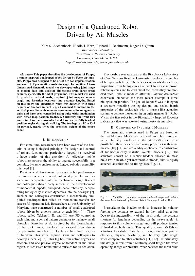
The pneumatic muscles used in Puppy are based onthe well-known McKibben artificial muscles describedin [9]. Initially developed in the late 1950’s for use inprosthetics, these devices share many properties with actualmuscle [10] [11] and are readily applicable to constructionof biomechanically realistic skeletal models [12]. Theactuators consist of a rubber bladder encased in meshbraid (with flexible yet inextensible strands) that is rigidlyattached at either end to fittings (see Fig. 1).
Fig. 1. McKibben pneumatic actuators relaxed (top) and inflated(bottom). Manufactured by Shadow Robot Company, London, U.K.
Pressurizing the bladder tends to increase its volume,forcing the actuator to expand in the radial direction.Due to the inextensibility of the mesh braid, the actuatorshortens (or lengthens depending on the weave angle) inresponse to this volume change and will produce tensionif loaded at both ends. This quality allows McKibbenactuators to exhibit variable stiffness, nonlinear passiveelasticity, physical flexibility, and be very light weightwhen compared to other actuators [11] [12]. Unfortunately,this design suffers from a relatively short fatigue life whenoperating at high air pressure. Wear between the mesh braid
and bladder causes the device to fail after 10,000 cycleswhen operating at 6 bar [13]. Designs by Shadow RobotCompany and others lasted indefinitely when operated ator below 3 bar.
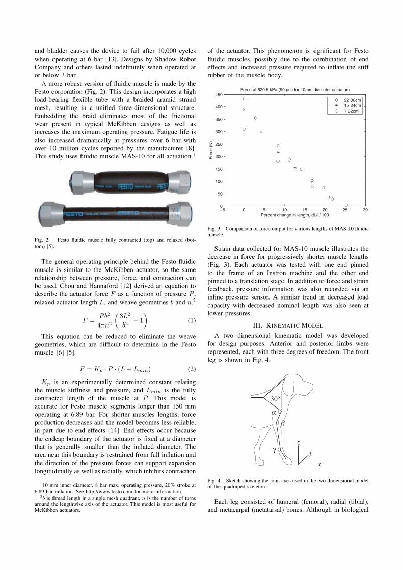
A more robust version of fluidic muscle is made by theFesto corporation (Fig. 2). This design incorporates a highload-bearing flexible tube with a braided aramid strandmesh, resulting in a unified three-dimensional structure.Embedding the braid eliminates most of the frictionalwear present in typical McKibben designs as well asincreases the maximum operating pressure. Fatigue life isalso increased dramatically at pressures over 6 bar withover 10 million cycles reported by the manufacturer [8].This study uses fluidic muscle MAS-10 for all actuation.1
Fig. 2. Festo fluidic muscle fully contracted (top) and relaxed (bot-tom) [5].
The general operating principle behind the Festo fluidicmuscle is similar to the McKibben actuator, so the samerelationship between pressure, force, and contraction canbe used. Chou and Hannaford [12] derived an equation todescribe the actuator force F as a function of pressure P ,relaxed actuator length L, and weave geometries b and n.2
F =Pb2
4πn2
(3L2
b2− 1
)(1)
This equation can be reduced to eliminate the weavegeometries, which are difficult to determine in the Festomuscle [6] [5].
F = Kp · P · (L− Lmin) (2)
Kp is an experimentally determined constant relatingthe muscle stiffness and pressure, and Lmin is the fullycontracted length of the muscle at P . This model isaccurate for Festo muscle segments longer than 150 mmoperating at 6.89 bar. For shorter muscles lengths, forceproduction decreases and the model becomes less reliable,in part due to end effects [14]. End effects occur becausethe endcap boundary of the actuator is fixed at a diameterthat is generally smaller than the inflated diameter. Thearea near this boundary is restrained from full inflation andthe direction of the pressure forces can support expansionlongitudinally as well as radially, which inhibits contraction
110 mm inner diameter, 8 bar max. operating pressure, 20% stroke at6.89 bar inflation. See http://www.festo.com for more information.
2b is thread length in a single mesh quadrant, n is the number of turnsaround the lengthwise axis of the actuator. This model is most useful forMcKibben actuators.
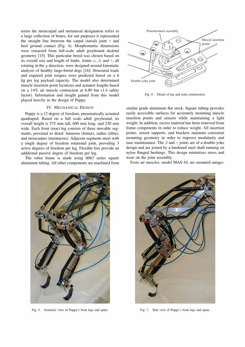
of the actuator. This phenomenon is significant for Festofluidic muscles, possibly due to the combination of endeffects and increased pressure required to inflate the stiffrubber of the muscle body.
Fig. 3. Comparison of force output for various lengths of MAS-10 fluidicmuscle.
Strain data collected for MAS-10 muscle illustrates thedecrease in force for progressively shorter muscle lengths(Fig. 3). Each actuator was tested with one end pinnedto the frame of an Instron machine and the other endpinned to a translation stage. In addition to force and strainfeedback, pressure information was also recorded via aninline pressure sensor. A similar trend in decreased loadcapacity with decreased nominal length was also seen atlower pressures.
III. KINEMATIC MODEL
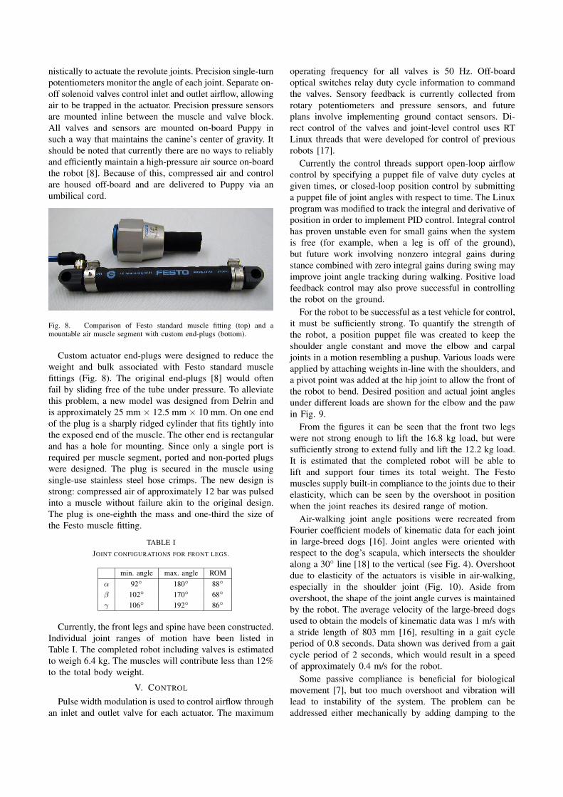
A two dimensional kinematic model was developedfor design purposes. Anterior and posterior limbs wererepresented, each with three degrees of freedom. The frontleg is shown in Fig. 4.
αβ
γ
30º45º
z
yx
Fig. 4. Sketch showing the joint axes used in the two-dimensional modelof the quadruped skeleton.
Each leg consisted of humeral (femoral), radial (tibial),and metacarpal (metatarsal) bones. Although in biological
terms the metacarpal and metatarsal designation refers toa large collection of bones, for our purposes it representedthe straight line between the carpal (tarsal) joint γ andheel ground contact (Fig. 4). Morphometric dimensionswere extracted from full-scale adult greyhound skeletalgeometry [15]. This particular breed was chosen based onits overall size and length of limbs. Joints α, β, and γ, allrotating in the y direction, were designed around kinematicanalysis of healthy large-breed dogs [16]. Structural loadsand required joint torques were predicted based on a 6kg per leg payload capacity. The model also determinedmuscle insertion point locations and actuator lengths basedon a 14% air muscle contraction at 6.89 bar (1.4 safetyfactor). Information and insight gained from this modelplayed heavily in the design of Puppy.
IV. MECHANICAL DESIGN
Puppy is a 12 degree of freedom, pneumatically actuatedquadruped. Based on a full scale adult greyhound, itsoverall height is 575 mm tall, 600 mm long, and 230 mmwide. Each front (rear) leg consists of three movable seg-ments, proximal to distal: humerus (femur), radius (tibia),and metacarpus (metatarsus). Adjacent segments meet witha single degree of freedom rotational joint, providing 3active degrees of freedom per leg. Flexible feet provide anadditional passive degree of freedom per leg.
The robot frame is made using 6063 series squarealuminum tubing. All other components are machined from
Fig. 5. Isometric view of Puppy’s front legs and spine.
Potentiometer assembly
Muscle insertion points
Double-yoke joint
Fig. 6. Detail of leg and joint construction.
similar grade aluminum flat stock. Square tubing provideseasily accessible surfaces for accurately mounting muscleinsertion points and sensors while maintaining a lightweight. In addition, excess material has been removed fromframe components in order to reduce weight. All insertionpoints, sensor supports, and brackets maintain consistentmounting geometry in order to improve modularity andease maintenance. The β and γ joints are of a double-yokedesign and are joined by a hardened steel shaft running onnylon flanged bushings. This design minimizes stress andwear on the joint assembly.
Festo air muscles, model MAS-10, are mounted antago-
Fig. 7. Side view of Puppy’s front legs and spine.
nistically to actuate the revolute joints. Precision single-turnpotentiometers monitor the angle of each joint. Separate on-off solenoid valves control inlet and outlet airflow, allowingair to be trapped in the actuator. Precision pressure sensorsare mounted inline between the muscle and valve block.All valves and sensors are mounted on-board Puppy insuch a way that maintains the canine’s center of gravity. Itshould be noted that currently there are no ways to reliablyand efficiently maintain a high-pressure air source on-boardthe robot [8]. Because of this, compressed air and controlare housed off-board and are delivered to Puppy via anumbilical cord.
Fig. 8. Comparison of Festo standard muscle fitting (top) and amountable air muscle segment with custom end-plugs (bottom).
Custom actuator end-plugs were designed to reduce theweight and bulk associated with Festo standard musclefittings (Fig. 8). The original end-plugs [8] would oftenfail by sliding free of the tube under pressure. To alleviatethis problem, a new model was designed from Delrin andis approximately 25 mm × 12.5 mm × 10 mm. On one endof the plug is a sharply ridged cylinder that fits tightly intothe exposed end of the muscle. The other end is rectangularand has a hole for mounting. Since only a single port isrequired per muscle segment, ported and non-ported plugswere designed. The plug is secured in the muscle usingsingle-use stainless steel hose crimps. The new design isstrong: compressed air of approximately 12 bar was pulsedinto a muscle without failure akin to the original design.The plug is one-eighth the mass and one-third the size ofthe Festo muscle fitting.
TABLE IJOINT CONFIGURATIONS FOR FRONT LEGS.
min. angle max. angle ROMα 92◦ 180◦ 88◦
β 102◦ 170◦ 68◦
γ 106◦ 192◦ 86◦
Currently, the front legs and spine have been constructed.Individual joint ranges of motion have been listed inTable I. The completed robot including valves is estimatedto weigh 6.4 kg. The muscles will contribute less than 12%to the total body weight.
V. CONTROL
Pulse width modulation is used to control airflow throughan inlet and outlet valve for each actuator. The maximum
operating frequency for all valves is 50 Hz. Off-boardoptical switches relay duty cycle information to commandthe valves. Sensory feedback is currently collected fromrotary potentiometers and pressure sensors, and futureplans involve implementing ground contact sensors. Di-rect control of the valves and joint-level control uses RTLinux threads that were developed for control of previousrobots [17].
Currently the control threads support open-loop airflowcontrol by specifying a puppet file of valve duty cycles atgiven times, or closed-loop position control by submittinga puppet file of joint angles with respect to time. The Linuxprogram was modified to track the integral and derivative ofposition in order to implement PID control. Integral controlhas proven unstable even for small gains when the systemis free (for example, when a leg is off of the ground),but future work involving nonzero integral gains duringstance combined with zero integral gains during swing mayimprove joint angle tracking during walking. Positive loadfeedback control may also prove successful in controllingthe robot on the ground.
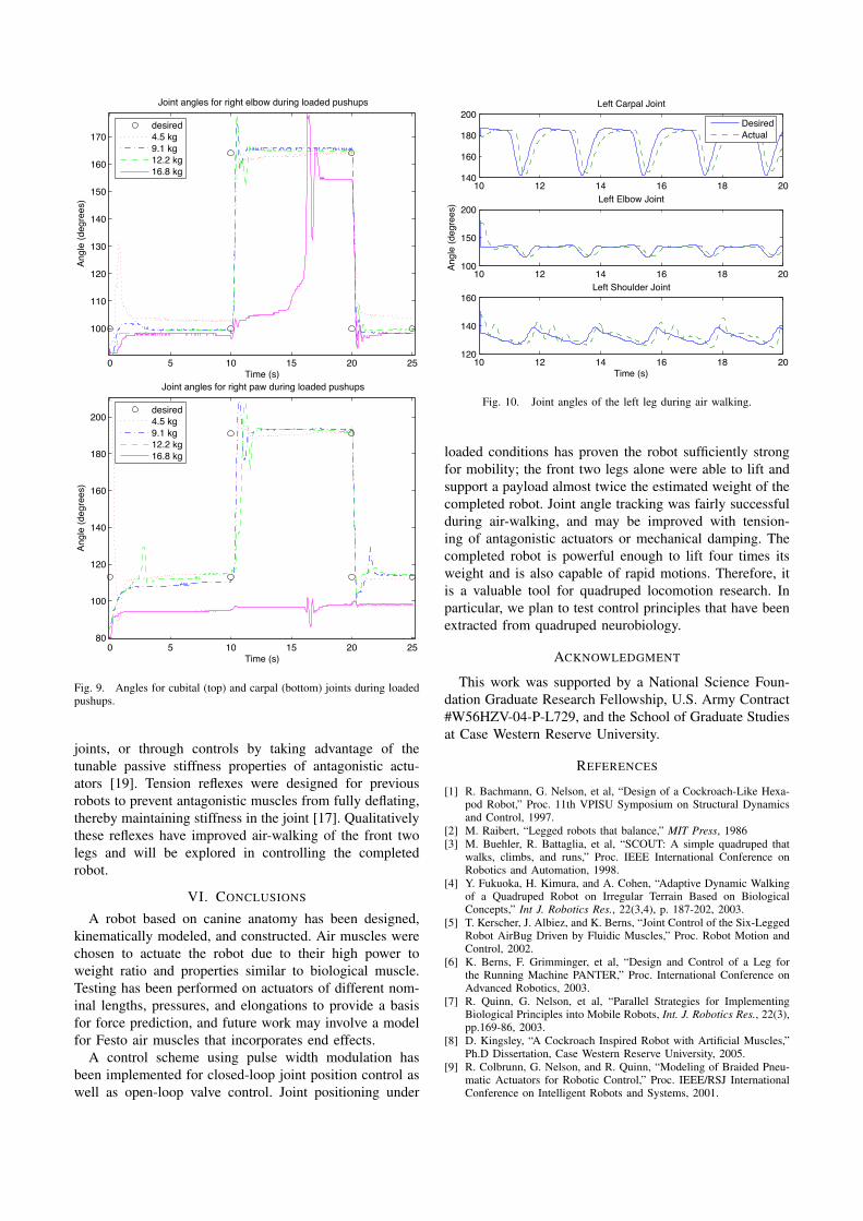
For the robot to be successful as a test vehicle for control,it must be sufficiently strong. To quantify the strength ofthe robot, a position puppet file was created to keep theshoulder angle constant and move the elbow and carpaljoints in a motion resembling a pushup. Various loads wereapplied by attaching weights in-line with the shoulders, anda pivot point was added at the hip joint to allow the front ofthe robot to bend. Desired position and actual joint anglesunder different loads are shown for the elbow and the pawin Fig. 9.
From the figures it can be seen that the front two legswere not strong enough to lift the 16.8 kg load, but weresufficiently strong to extend fully and lift the 12.2 kg load.It is estimated that the completed robot will be able tolift and support four times its total weight. The Festomuscles supply built-in compliance to the joints due to theirelasticity, which can be seen by the overshoot in positionwhen the joint reaches its desired range of motion.
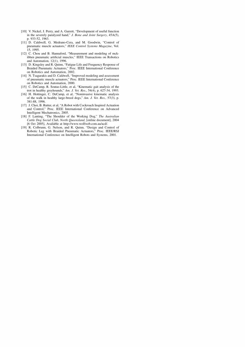
Air-walking joint angle positions were recreated fromFourier coefficient models of kinematic data for each jointin large-breed dogs [16]. Joint angles were oriented withrespect to the dog’s scapula, which intersects the shoulderalong a 30◦ line [18] to the vertical (see Fig. 4). Overshootdue to elasticity of the actuators is visible in air-walking,especially in the shoulder joint (Fig. 10). Aside fromovershoot, the shape of the joint angle curves is maintainedby the robot. The average velocity of the large-breed dogsused to obtain the models of kinematic data was 1 m/s witha stride length of 803 mm [16], resulting in a gait cycleperiod of 0.8 seconds. Data shown was derived from a gaitcycle period of 2 seconds, which would result in a speedof approximately 0.4 m/s for the robot.
Some passive compliance is beneficial for biologicalmovement [7], but too much overshoot and vibration willlead to instability of the system. The problem can beaddressed either mechanically by adding damping to the
0 5 10 15 20 25
100
110
120
130
140
150
160
170
Time (s)
Angl
e (d
egre
es)
Joint angles for right elbow during loaded pushups
desired4.5 kg9.1 kg12.2 kg16.8 kg
0 5 10 15 20 2580
100
120
140
160
180
200
Time (s)
Angl
e (d
egre
es)
Joint angles for right paw during loaded pushups
desired4.5 kg9.1 kg12.2 kg16.8 kg
Fig. 9. Angles for cubital (top) and carpal (bottom) joints during loadedpushups.
joints, or through controls by taking advantage of thetunable passive stiffness properties of antagonistic actu-ators [19]. Tension reflexes were designed for previousrobots to prevent antagonistic muscles from fully deflating,thereby maintaining stiffness in the joint [17]. Qualitativelythese reflexes have improved air-walking of the front twolegs and will be explored in controlling the completedrobot.
VI. CONCLUSIONS
A robot based on canine anatomy has been designed,kinematically modeled, and constructed. Air muscles werechosen to actuate the robot due to their high power toweight ratio and properties similar to biological muscle.Testing has been performed on actuators of different nom-inal lengths, pressures, and elongations to provide a basisfor force prediction, and future work may involve a modelfor Festo air muscles that incorporates end effects.
A control scheme using pulse width modulation hasbeen implemented for closed-loop joint position control aswell as open-loop valve control. Joint positioning under
Fig. 10. Joint angles of the left leg during air walking.
loaded conditions has proven the robot sufficiently strongfor mobility; the front two legs alone were able to lift andsupport a payload almost twice the estimated weight of thecompleted robot. Joint angle tracking was fairly successfulduring air-walking, and may be improved with tension-ing of antagonistic actuators or mechanical damping. Thecompleted robot is powerful enough to lift four times itsweight and is also capable of rapid motions. Therefore, itis a valuable tool for quadruped locomotion research. Inparticular, we plan to test control principles that have beenextracted from quadruped neurobiology.
ACKNOWLEDGMENT
This work was supported by a National Science Foun-dation Graduate Research Fellowship, U.S. Army Contract#W56HZV-04-P-L729, and the School of Graduate Studiesat Case Western Reserve University.
REFERENCES
[1] R. Bachmann, G. Nelson, et al, “Design of a Cockroach-Like Hexa-pod Robot,” Proc. 11th VPISU Symposium on Structural Dynamicsand Control, 1997.
[2] M. Raibert, “Legged robots that balance,” MIT Press, 1986[3] M. Buehler, R. Battaglia, et al, “SCOUT: A simple quadruped that
walks, climbs, and runs,” Proc. IEEE International Conference onRobotics and Automation, 1998.
[4] Y. Fukuoka, H. Kimura, and A. Cohen, “Adaptive Dynamic Walkingof a Quadruped Robot on Irregular Terrain Based on BiologicalConcepts,” Int J. Robotics Res., 22(3,4), p. 187-202, 2003.
[5] T. Kerscher, J. Albiez, and K. Berns, “Joint Control of the Six-LeggedRobot AirBug Driven by Fluidic Muscles,” Proc. Robot Motion andControl, 2002.
[6] K. Berns, F. Grimminger, et al, “Design and Control of a Leg forthe Running Machine PANTER,” Proc. International Conference onAdvanced Robotics, 2003.
[7] R. Quinn, G. Nelson, et al, “Parallel Strategies for ImplementingBiological Principles into Mobile Robots, Int. J. Robotics Res., 22(3),pp.169-86, 2003.
[8] D. Kingsley, “A Cockroach Inspired Robot with Artificial Muscles,”Ph.D Dissertation, Case Western Reserve University, 2005.
[9] R. Colbrunn, G. Nelson, and R. Quinn, “Modeling of Braided Pneu-matic Actuators for Robotic Control,” Proc. IEEE/RSJ InternationalConference on Intelligent Robots and Systems, 2001.
[10] V. Nickel, J. Perry, and A. Garrett, “Development of useful functionin the severely paralyzed hand,” J. Bone and Joint Surgery, 45A(5),p. 933-52, 1963.
[11] D. Caldwell, G. Medrano-Cera, and M. Goodwin, “Control ofpneumatic muscle actuators,” IEEE Control Systems Magazine, Vol.15, 1995.
[12] C. Chou and B. Hannaford, “Measurement and modeling of mck-ibben pneumatic artificial muscles,” IEEE Transactions on Roboticsand Automation, 12(1), 1996.
[13] D. Kingsley and R. Quinn, “Fatigue Life and Frequency Response ofBraided Pneumatic Actuators,” Proc. IEEE International Conferenceon Robotics and Automation, 2002.
[14] N. Tsagarakis and D. Caldwell, “Improved modeling and assessmentof pneumatic muscle actuators,” Proc. IEEE International Conferenceon Robotics and Automation, 2000.
[15] C. DeCamp, R. Soutas-Little, et al, “Kinematic gait analysis of thetrot in healthy greyhounds,” Am. J. Vet. Res., 54(4), p. 627-34, 1993.
[16] H. Hottinger, C. DeCamp, et al, “Noninvasive kinematic analysisof the walk in healthy large-breed dogs,” Am. J. Vet. Res., 57(3), p.381-88, 1996.
[17] J. Choi, B. Rutter, et al, “A Robot with Cockroach Inspired Actuationand Control,” Proc. IEEE International Conference on AdvancedIntelligent Mechatronics, 2005.
[18] F. Lanting, “The Shoulder of the Working Dog,” The AustralianCattle Dog Social Club, North Queensland, [online document], 2004[6 Oct 2005], Available at http://www.wolfweb.com.au/acd/.
[19] R. Colbrunn, G. Nelson, and R. Quinn, “Design and Control ofRobotic Leg with Braided Pneumatic Actuators,” Proc. IEEE/RSJInternational Conference on Intelligent Robots and Systems, 2001.