offshore structures versus land-based structures
TRANSCRIPT
Chapter 2Offshore Structures Versus Land-BasedStructures
2.1 Introduction to Offshore Structures
2.1.1 Offshore Platforms
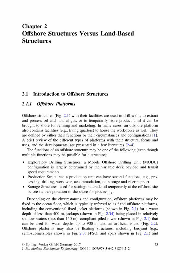
Offshore structures (Fig. 2.1) with their facilities are used to drill wells, to extractand process oil and natural gas, or to temporarily store product until it can bebrought to shore for refining and marketing. In many cases, an offshore platformalso contains facilities (e.g., living quarters) to house the work-force as well. Theyare defined by either their functions or their circumstances and configurations [1].A brief review of the different types of platforms with their structural forms anduses, and the developments, are presented in a few literatures [2–4].
The functions of an offshore structure may be one of the following (even thoughmultiple functions may be possible for a structure):
• Exploratory Drilling Structures: a Mobile Offshore Drilling Unit (MODU)configuration is largely determined by the variable deck payload and transitspeed requirements.
• Production Structures: a production unit can have several functions, e.g., pro-cessing, drilling, workover, accommodation, oil storage and riser support.
• Storage Structures: used for storing the crude oil temporarily at the offshore sitebefore its transportation to the shore for processing.
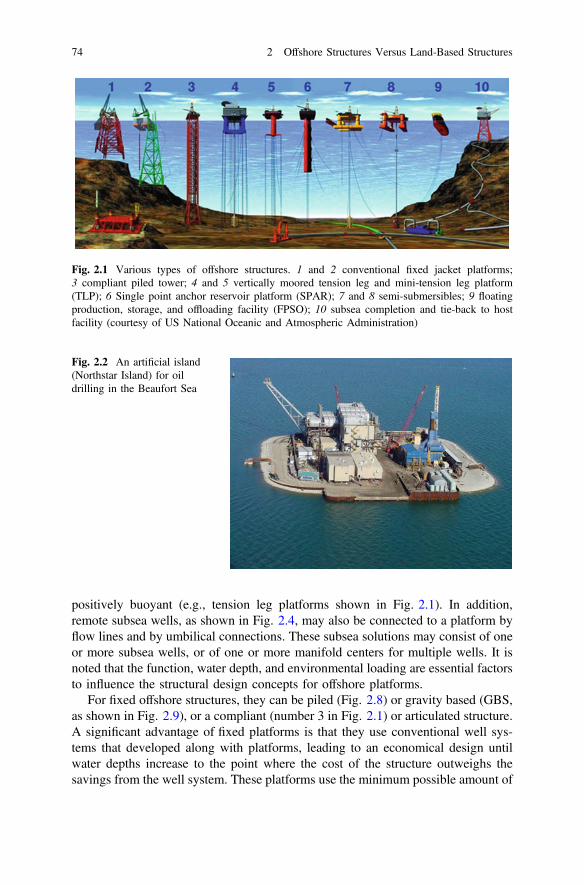
Depending on the circumstances and configuration, offshore platforms may befixed to the ocean floor, which is typically referred to as fixed offshore platforms,including the conventional fixed jacket platforms (shown in Fig. 2.1) for a waterdepth of less than 400 m, jackups (shown in Fig. 2.34) being placed in relativelyshallow waters (less than 150 m), compliant piled tower (shown in Fig. 2.1) thatcan be used for water depths up to 900 m, and an artificial island (Fig. 2.2).Offshore platforms may also be floating structures, including buoyant (e.g.,semi-submersibles shown in Fig. 2.3, FPSO, and spars shown in Fig. 2.1) and
© Springer-Verlag GmbH Germany 2017J. Jia, Modern Earthquake Engineering, DOI 10.1007/978-3-642-31854-2_2
73
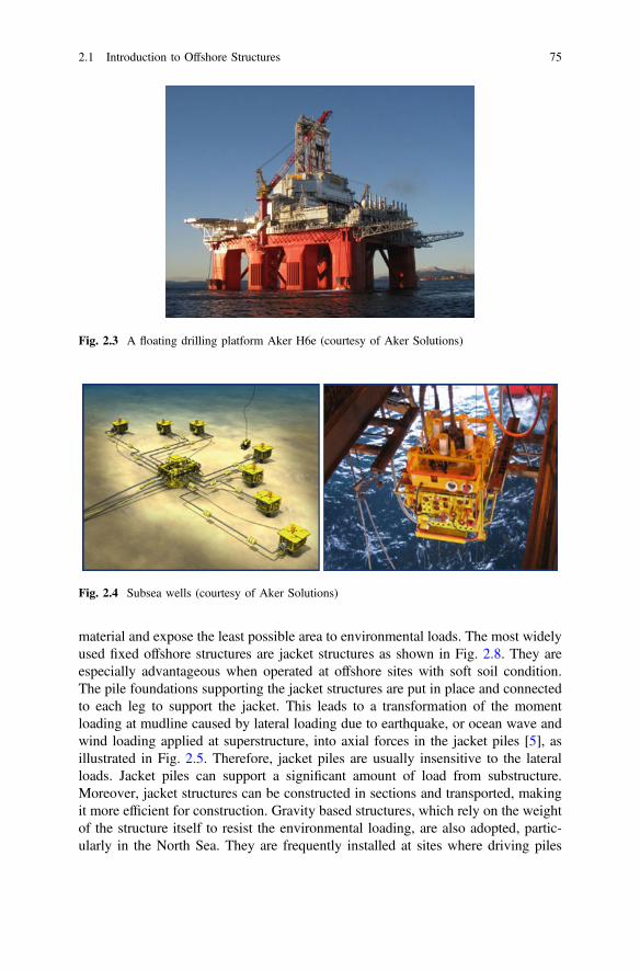
positively buoyant (e.g., tension leg platforms shown in Fig. 2.1). In addition,remote subsea wells, as shown in Fig. 2.4, may also be connected to a platform byflow lines and by umbilical connections. These subsea solutions may consist of oneor more subsea wells, or of one or more manifold centers for multiple wells. It isnoted that the function, water depth, and environmental loading are essential factorsto influence the structural design concepts for offshore platforms.
For fixed offshore structures, they can be piled (Fig. 2.8) or gravity based (GBS,as shown in Fig. 2.9), or a compliant (number 3 in Fig. 2.1) or articulated structure.A significant advantage of fixed platforms is that they use conventional well sys-tems that developed along with platforms, leading to an economical design untilwater depths increase to the point where the cost of the structure outweighs thesavings from the well system. These platforms use the minimum possible amount of
Fig. 2.1 Various types of offshore structures. 1 and 2 conventional fixed jacket platforms;3 compliant piled tower; 4 and 5 vertically moored tension leg and mini-tension leg platform(TLP); 6 Single point anchor reservoir platform (SPAR); 7 and 8 semi-submersibles; 9 floatingproduction, storage, and offloading facility (FPSO); 10 subsea completion and tie-back to hostfacility (courtesy of US National Oceanic and Atmospheric Administration)
Fig. 2.2 An artificial island(Northstar Island) for oildrilling in the Beaufort Sea
74 2 Offshore Structures Versus Land-Based Structures
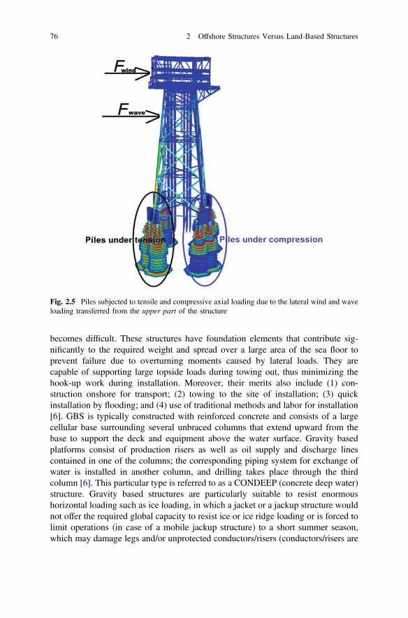
material and expose the least possible area to environmental loads. The most widelyused fixed offshore structures are jacket structures as shown in Fig. 2.8. They areespecially advantageous when operated at offshore sites with soft soil condition.The pile foundations supporting the jacket structures are put in place and connectedto each leg to support the jacket. This leads to a transformation of the momentloading at mudline caused by lateral loading due to earthquake, or ocean wave andwind loading applied at superstructure, into axial forces in the jacket piles [5], asillustrated in Fig. 2.5. Therefore, jacket piles are usually insensitive to the lateralloads. Jacket piles can support a significant amount of load from substructure.Moreover, jacket structures can be constructed in sections and transported, makingit more efficient for construction. Gravity based structures, which rely on the weightof the structure itself to resist the environmental loading, are also adopted, partic-ularly in the North Sea. They are frequently installed at sites where driving piles
Fig. 2.3 A floating drilling platform Aker H6e (courtesy of Aker Solutions)
Fig. 2.4 Subsea wells (courtesy of Aker Solutions)
2.1 Introduction to Offshore Structures 75
becomes difficult. These structures have foundation elements that contribute sig-nificantly to the required weight and spread over a large area of the sea floor toprevent failure due to overturning moments caused by lateral loads. They arecapable of supporting large topside loads during towing out, thus minimizing thehook-up work during installation. Moreover, their merits also include (1) con-struction onshore for transport; (2) towing to the site of installation; (3) quickinstallation by flooding; and (4) use of traditional methods and labor for installation[6]. GBS is typically constructed with reinforced concrete and consists of a largecellular base surrounding several unbraced columns that extend upward from thebase to support the deck and equipment above the water surface. Gravity basedplatforms consist of production risers as well as oil supply and discharge linescontained in one of the columns; the corresponding piping system for exchange ofwater is installed in another column, and drilling takes place through the thirdcolumn [6]. This particular type is referred to as a CONDEEP (concrete deep water)structure. Gravity based structures are particularly suitable to resist enormoushorizontal loading such as ice loading, in which a jacket or a jackup structure wouldnot offer the required global capacity to resist ice or ice ridge loading or is forced tolimit operations (in case of a mobile jackup structure) to a short summer season,which may damage legs and/or unprotected conductors/risers (conductors/risers are
Fig. 2.5 Piles subjected to tensile and compressive axial loading due to the lateral wind and waveloading transferred from the upper part of the structure
76 2 Offshore Structures Versus Land-Based Structures
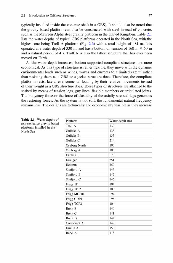
typically installed inside the concrete shaft in a GBS). It should also be noted thatthe gravity based platform can also be constructed with steel instead of concrete,such as the Maureen Alpha steel gravity platform in the United Kingdom. Table 2.1lists the water depths of typical GBS platforms operated in the North Sea, with thehighest one being Troll A platform (Fig. 2.6) with a total height of 481 m. It isoperated at a water depth of 330 m, and has a bottom dimension of 160 m × 60 mand a natural period of 4 s. Troll A is also the tallest structure that has ever beenmoved on Earth.
As the water depth increases, bottom supported compliant structures are moreeconomical. As this type of structure is rather flexible, they move with the dynamicenvironmental loads such as winds, waves and currents to a limited extent, ratherthan resisting them as a GBS or a jacket structure does. Therefore, the compliantplatforms resist lateral environmental loading by their relative movements insteadof their weight as a GBS structure does. These types of structures are attached to theseabed by means of tension legs, guy lines, flexible members or articulated joints.The buoyancy force or the force of elasticity of the axially stressed legs generatesthe restoring forces. As the system is not soft, the fundamental natural frequencyremains low. The designs are technically and economically feasible as they increase
Table 2.1 Water depths ofrepresentative gravity basedplatforms installed in theNorth Sea
Platform Water depth (m)
Troll A 330
Gulfaks A 133
Gulfaks B 133
Gulfaks C 214
Oseberg North 100
Oseberg A 100
Ekofisk 1 70
Draugen 251
Heidrun 350
Statfjord A 145
Statfjord B 145
Statfjord C 145
Frigg TP 1 104
Frigg TP 2 103
Frigg MCP01 94
Frigg CDP1 98
Frigg TCP2 104
Brent B 140
Brent C 141
Brent D 142
Cormorant A 149
Dunlin A 153
Beryl A 118
2.1 Introduction to Offshore Structures 77
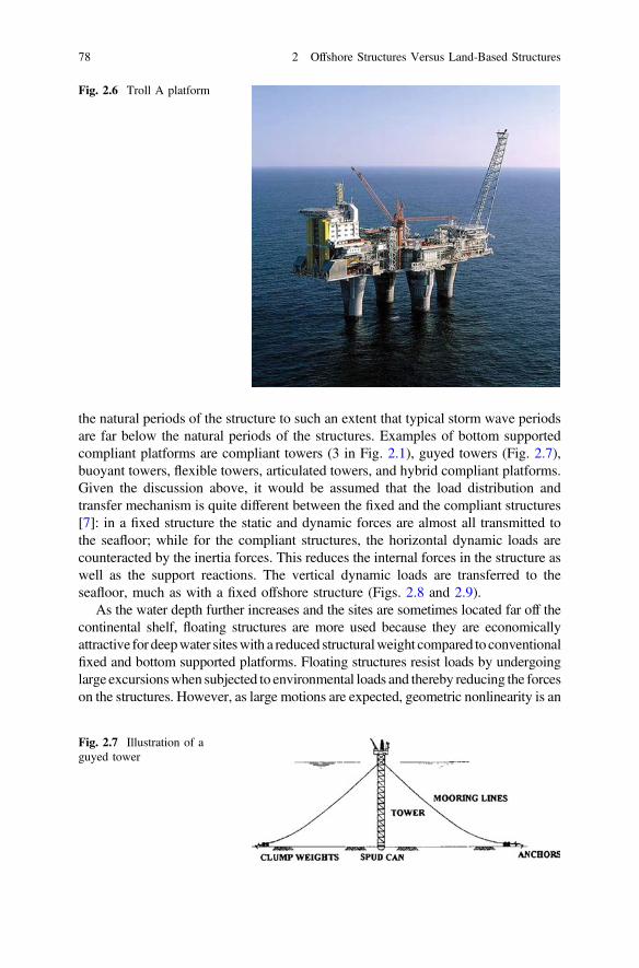
the natural periods of the structure to such an extent that typical storm wave periodsare far below the natural periods of the structures. Examples of bottom supportedcompliant platforms are compliant towers (3 in Fig. 2.1), guyed towers (Fig. 2.7),buoyant towers, flexible towers, articulated towers, and hybrid compliant platforms.Given the discussion above, it would be assumed that the load distribution andtransfer mechanism is quite different between the fixed and the compliant structures[7]: in a fixed structure the static and dynamic forces are almost all transmitted tothe seafloor; while for the compliant structures, the horizontal dynamic loads arecounteracted by the inertia forces. This reduces the internal forces in the structure aswell as the support reactions. The vertical dynamic loads are transferred to theseafloor, much as with a fixed offshore structure (Figs. 2.8 and 2.9).
As the water depth further increases and the sites are sometimes located far off thecontinental shelf, floating structures are more used because they are economicallyattractive for deepwater siteswith a reduced structuralweight compared to conventionalfixed and bottom supported platforms. Floating structures resist loads by undergoinglarge excursionswhen subjected to environmental loads and thereby reducing the forceson the structures. However, as large motions are expected, geometric nonlinearity is an
Fig. 2.6 Troll A platform
Fig. 2.7 Illustration of aguyed tower
78 2 Offshore Structures Versus Land-Based Structures
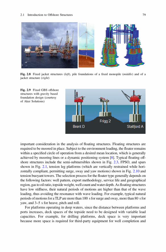
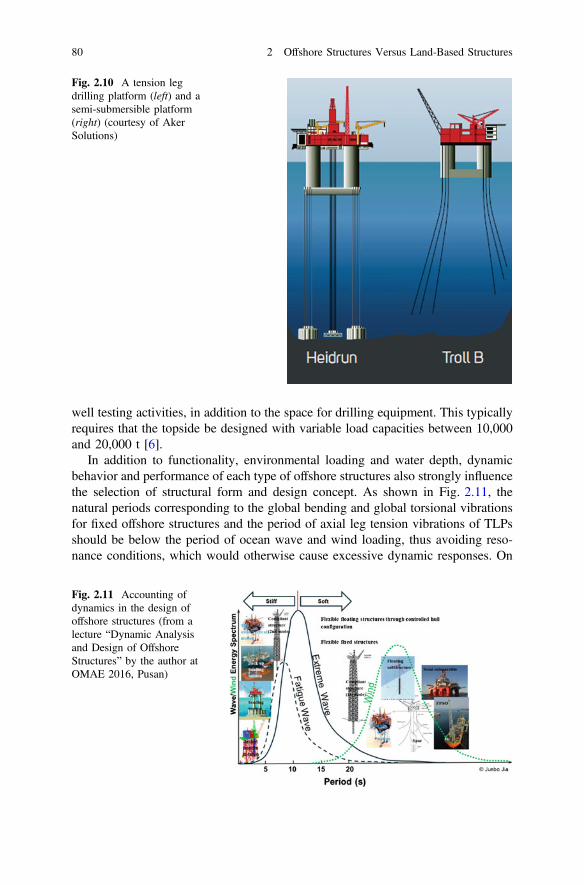
important consideration in the analysis of floating structures. Floating structures arerequired to be moored in place. Subject to the environment loading, the floater remainswithin a specified circle of operation from a desired mean location, which is generallyachieved by mooring lines or a dynamic positioning system [8]. Typical floating off-shore structures include the semi-submersibles shown in Fig. 2.3, FPSO, and sparsshown in Fig. 2.1, tension leg platforms (which are vertically restrained while hori-zontally compliant, permitting surge, sway and yaw motions) shown in Fig. 2.10 andtension buoyant towers. The selection process for the floater type generally depends onthe following factors: well pattern, export methodology, service life and geographicalregion, gas to oil ratio, topsideweight,well count andwater depth.Asfloating structureshave low stiffness, their natural periods of motions are higher than that of the waveloading, thus avoiding the resonance with wave loading. For example, typical naturalperiods ofmotions for a TLP aremore than 100 s for surge and sway,more than 80 s foryaw, and 3–5 s for heave, pitch and roll.
For platforms operating in deep waters, since the distance between platforms andports increases, deck spaces of the topside need to be designed with variable loadcapacities. For example, for drilling platforms, deck space is very importantbecause more space is required for third-party equipment for well completion and
Fig. 2.8 Fixed jacket structures (left), pile foundations of a fixed monopile (middle) and of ajacket structure (right)
Fig. 2.9 Fixed GBS offshorestructures with gravity basedfoundation design (courtesyof Aker Solutions)
2.1 Introduction to Offshore Structures 79
well testing activities, in addition to the space for drilling equipment. This typicallyrequires that the topside be designed with variable load capacities between 10,000and 20,000 t [6].
In addition to functionality, environmental loading and water depth, dynamicbehavior and performance of each type of offshore structures also strongly influencethe selection of structural form and design concept. As shown in Fig. 2.11, thenatural periods corresponding to the global bending and global torsional vibrationsfor fixed offshore structures and the period of axial leg tension vibrations of TLPsshould be below the period of ocean wave and wind loading, thus avoiding reso-nance conditions, which would otherwise cause excessive dynamic responses. On
Fig. 2.10 A tension legdrilling platform (left) and asemi-submersible platform(right) (courtesy of AkerSolutions)
Fig. 2.11 Accounting ofdynamics in the design ofoffshore structures (from alecture “Dynamic Analysisand Design of OffshoreStructures” by the author atOMAE 2016, Pusan)
80 2 Offshore Structures Versus Land-Based Structures
the other hand, to avoid resonance motion responses of floating structures due towave loading (normally the dominating loads for offshore structural designs), theygenerally have natural periods of motions higher than the period of ocean waveloadings, even though they may potentially reach a resonance condition due todynamic loading caused by wind turbulence.
Typically, the design of fixed offshore structures has to consider the impact fromearthquakes. The design of TLP also needs to consider the influence from theseismic loading transferred to tension leg(s) and the response of connected floatingstructures.
2.1.2 Offshore Wind Turbine Substructuresand Foundations
Offshore sites provide a reliable source of strong winds due to the cooling andheating effect of water and land. Moreover, wind turbulence offshore is generallylower than that of inland sites. Therefore, due to the higher wind speed and lowerwind turbulence offshore than over adjoining land, in recent years, offshore windfarms have rapidly developed across the world, dominated by developers in Europeand East Asia. In the meantime, the United States is also catching up by completingits first offshore wind farm with five steel jacket substructures (each carry a 6 MWwind turbine), installed at the Block Island Wind Farm site in December 2015. Sofar, more than 80 % of the operated and currently planned offshore wind farms arelocated in Europe.
A wind turbine-supporting structure system includes both rotor-nacelle assemblyand support structure. The former includes rotor (blades and hub) and nacelleassembly (all components above tower except the rotor, including driven train, bedplate, yaw system, and nacelle enclosure, etc.). The latter include a tower (con-necting the substructure to rotor-nacelle assembly), substructure (for fixed sub-structure, it extends upwards from the seabed and connects the foundation to thetower; for floating substructure, it is the part below the tower), and foundation(transferring various types of load acting on the structure into the seabed soil).
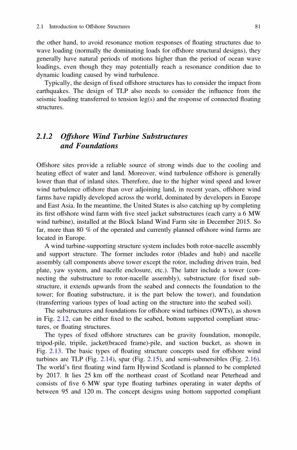
The substructures and foundations for offshore wind turbines (OWTs), as shownin Fig. 2.12, can be either fixed to the seabed, bottom supported compliant struc-tures, or floating structures.
The types of fixed offshore structures can be gravity foundation, monopile,tripod-pile, tripile, jacket(braced frame)-pile, and suction bucket, as shown inFig. 2.13. The basic types of floating structure concepts used for offshore windturbines are TLP (Fig. 2.14), spar (Fig. 2.15), and semi-submersibles (Fig. 2.16).The world’s first floating wind farm Hywind Scotland is planned to be completedby 2017. It lies 25 km off the northeast coast of Scotland near Peterhead andconsists of five 6 MW spar type floating turbines operating in water depths ofbetween 95 and 120 m. The concept designs using bottom supported compliant
2.1 Introduction to Offshore Structures 81
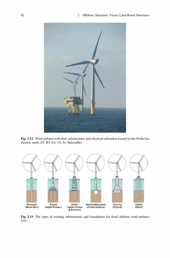
Fig. 2.12 Wind turbines with their substructures and electrical substation located in the North Sea(license under CC BY-SA 3.0, by StekrueBe)
Fig. 2.13 The types of existing substructures and foundations for fixed offshore wind turbines[16]
82 2 Offshore Structures Versus Land-Based Structures
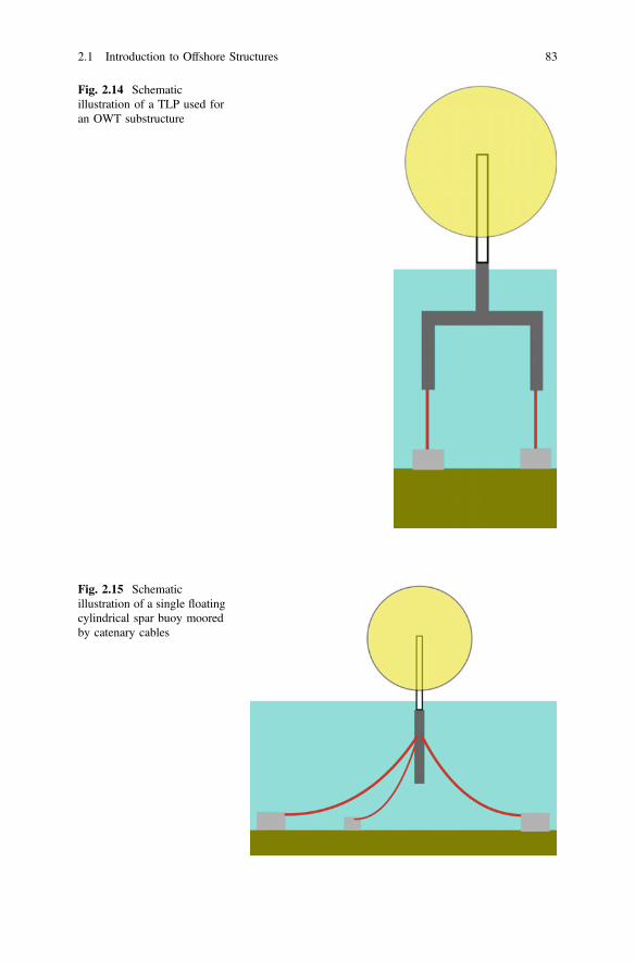
Fig. 2.14 Schematicillustration of a TLP used foran OWT substructure
Fig. 2.15 Schematicillustration of a single floatingcylindrical spar buoy mooredby catenary cables
2.1 Introduction to Offshore Structures 83
structures for OWTs have not received much popularity, because the low frequencywind turbulence may interfere with the natural frequency of the compliant structure,potentially causing resonance. Moreover, the interaction between a compliantstructure and the wind turbine can exert significant forces on the top of the rela-tively flexible structure, leading to significant deflections of the compliant structure.
Monopile currently represents themost common substructure application forOWTin shallow waters. It is a relatively simple design in which the tower to supportingturbines, made up of steel pipe, is supported by the monopole, either directly orthrough a transition piece. The vertical loads are transferred to the seabed by shaftfriction and tip resistance. The vertical bearing capacity is therefore largely deter-mined by the diameter of the mono pile (typically between 2 and 6 m), which attractsthe lateral hydrodynamic loads due towind,waves and current. These horizontal loadsdominated by bending moments will be further transferred to the soil. Monopile is sofar a cost competitive solution and suitable for shallowwaters up to 30m. One criticalissue for the design of monopiles is the consideration of cyclic behavior of piles withlarge diameter. Investigations have shown that the horizontal deflections of largediameter monopiles are underestimated for extreme loads [5]. On the other hand,experiences from operating offshore wind farms supported bymonopiles indicate thatthe foundation stiffness for small operational loads is significantly underestimated.The installation method involves lifting or floating the structure into position usingequipment such as floating crane vessels, drilling jack-up units, and specially con-structed installation vessels before driving the piles into the seabed.
Jacket designs are more and more utilized in the applications of OWT. As anexample, jacket structures were chosen as substructures by the Moray OffshoreWind Farm project (1500 MW total) in the UK, with up to 8 MW for each offshorewind turbine. The obvious benefits (compare to a monopile) are the reduction inhydrodynamic loading and weight, and suitability for increased water depth(30 m+). Jacket structures are less dependent on soil conditions compared tomonopile and tripod, and are more suitable for sites with soft soil conditions.
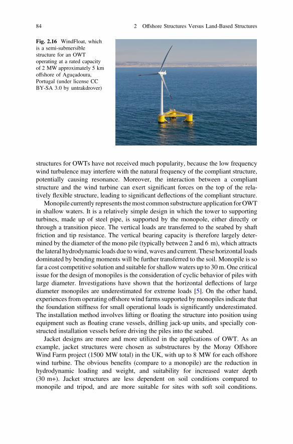
Fig. 2.16 WindFloat, whichis a semi-submersiblestructure for an OWToperating at a rated capacityof 2 MW approximately 5 kmoffshore of Aguçadoura,Portugal (under license CCBY-SA 3.0 by untrakdrover)
84 2 Offshore Structures Versus Land-Based Structures
They are easily capable of supporting OWT with 6 MW or more. The smallerdiameter of the piles (typically less than 2.5 m) also means a reduction in requireddriving power and less noise during piling. In addition, better precision for pileorientation and positioning can be ensured. By considering the financial limits,OWT using jacket works well for water depths up to 60 m.
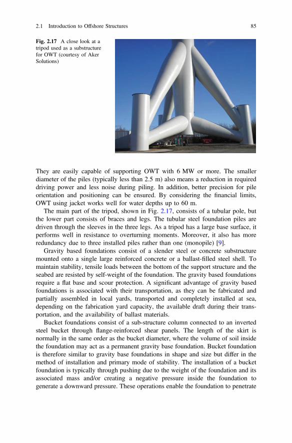
The main part of the tripod, shown in Fig. 2.17, consists of a tubular pole, butthe lower part consists of braces and legs. The tubular steel foundation piles aredriven through the sleeves in the three legs. As a tripod has a large base surface, itperforms well in resistance to overturning moments. Moreover, it also has moreredundancy due to three installed piles rather than one (monopile) [9].
Gravity based foundations consist of a slender steel or concrete substructuremounted onto a single large reinforced concrete or a ballast-filled steel shell. Tomaintain stability, tensile loads between the bottom of the support structure and theseabed are resisted by self-weight of the foundation. The gravity based foundationsrequire a flat base and scour protection. A significant advantage of gravity basedfoundations is associated with their transportation, as they can be fabricated andpartially assembled in local yards, transported and completely installed at sea,depending on the fabrication yard capacity, the available draft during their trans-portation, and the availability of ballast materials.
Bucket foundations consist of a sub-structure column connected to an invertedsteel bucket through flange-reinforced shear panels. The length of the skirt isnormally in the same order as the bucket diameter, where the volume of soil insidethe foundation may act as a permanent gravity base foundation. Bucket foundationis therefore similar to gravity base foundations in shape and size but differ in themethod of installation and primary mode of stability. The installation of a bucketfoundation is typically through pushing due to the weight of the foundation and itsassociated mass and/or creating a negative pressure inside the foundation togenerate a downward pressure. These operations enable the foundation to penetrate
Fig. 2.17 A close look at atripod used as a substructurefor OWT (courtesy of AkerSolutions)
2.1 Introduction to Offshore Structures 85
into the seabed and to finally reach a desirable penetration depth. To create thenegative pressure, water and air inside the foundation are pumped out through topof bucket when the rim of bucket seals with the seabed.
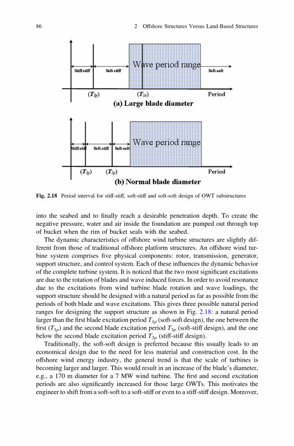
The dynamic characteristics of offshore wind turbine structures are slightly dif-ferent from those of traditional offshore platform structures. An offshore wind tur-bine system comprises five physical components: rotor, transmission, generator,support structure, and control system. Each of these influences the dynamic behaviorof the complete turbine system. It is noticed that the two most significant excitationsare due to the rotation of blades and wave induced forces. In order to avoid resonancedue to the excitations from wind turbine blade rotation and wave loadings, thesupport structure should be designed with a natural period as far as possible from theperiods of both blade and wave excitations. This gives three possible natural periodranges for designing the support structure as shown in Fig. 2.18: a natural periodlarger than the first blade excitation period T1p (soft-soft design), the one between thefirst (T1p) and the second blade excitation period T3p (soft-stiff design), and the onebelow the second blade excitation period T3p (stiff-stiff design).
Traditionally, the soft-soft design is preferred because this usually leads to aneconomical design due to the need for less material and construction cost. In theoffshore wind energy industry, the general trend is that the scale of turbines isbecoming larger and larger. This would result in an increase of the blade’s diameter,e.g., a 170 m diameter for a 7 MW wind turbine. The first and second excitationperiods are also significantly increased for those large OWTs. This motivates theengineer to shift from a soft-soft to a soft-stiff or even to a stiff-stiff design. Moreover,
Fig. 2.18 Period interval for stiff-stiff, soft-stiff and soft-soft design of OWT substructures
86 2 Offshore Structures Versus Land-Based Structures
the variable tip speed of the turbine also becomes a design alternative, which addsadditional restrictions on the natural period range of the structures. In addition, it isalso possible to convert the existing/abandoned offshore rigs into substructures forOWT systems, which can avoid/delay enormous decommissioning costs for energycompanies as well as avoid cost and pollution for constructing new substructures forOWTs. Most of the existing fixed offshore platform structures have natural periodsbelow 3.5 s; after removing part of the heavy topside modules at the top of theplatforms, the natural periods will further decrease. This period range is then relevantto the soft-stiff or even soft-soft design. For developing this concept, one also needs toaccount for the cost with respect to maintenance and power grid integration.
Except artificial damping devices, an optimized control system and the associ-ated control algorithm for both generator torque and pitch angle of wind turbineblades (either for a collective pitch control for all blades or an individual pitchcontrol for each blade) can also mitigate dynamic loadings applied on an OWTtower. Such a control supplies additional damping to generally lightly-dampedtower, and may even help to minimize both wind and wave induced platformmotions. It normally involves a modeling of an extra pitch demand responsible forcounter-balancing the vibrations and motions of the tower. This load reduction willallow for a more cost-effective structural design.
2.2 Accounting of Dynamics in the Concept Designof Structures
2.2.1 Dynamics Versus Statics
Over history, the safety and serviceability of structures have basically been mea-sured on the basis of their static behavior, which required adequate stiffness andstrength. This was perhaps because the necessary knowledge of dynamics was lessaccessible to engineers than their static counterpart. Nowadays, it is commonknowledge that all bodies possessing stiffness and mass are capable of exhibitingdynamic behavior.
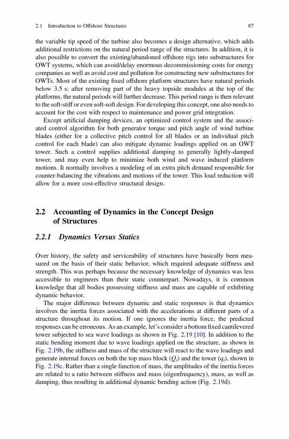
The major difference between dynamic and static responses is that dynamicsinvolves the inertia forces associated with the accelerations at different parts of astructure throughout its motion. If one ignores the inertia force, the predictedresponses can be erroneous. As an example, let’s consider a bottom fixed cantileveredtower subjected to sea wave loadings as shown in Fig. 2.19 [10]. In addition to thestatic bending moment due to wave loadings applied on the structure, as shown inFig. 2.19b, the stiffness and mass of the structure will react to the wave loadings andgenerate internal forces on both the top mass block (Qi) and the tower (qi), shown inFig. 2.19c. Rather than a single function of mass, the amplitudes of the inertia forcesare related to a ratio between stiffness and mass (eigenfrequency), mass, as well asdamping, thus resulting in additional dynamic bending action (Fig. 2.19d).
2.1 Introduction to Offshore Structures 87
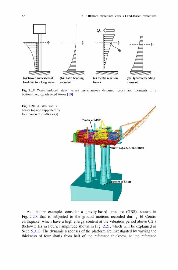
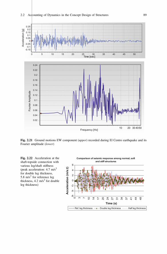
As another example, consider a gravity-based structure (GBS), shown inFig. 2.20, that is subjected to the ground motions recorded during El Centroearthquake, which have a high energy content at the vibration period above 0.2 s(below 5 Hz in Fourier amplitude shown in Fig. 2.21, which will be explained inSect. 5.3.1). The dynamic responses of the platform are investigated by varying thethickness of four shafts from half of the reference thickness, to the reference
Fig. 2.20 A GBS with aheavy topside supported byfour concrete shafts (legs)
Fig. 2.19 Wave induced static versus instantaneous dynamic forces and moments in abottom-fixed cantilevered tower [10]
88 2 Offshore Structures Versus Land-Based Structures
Time [sec]50454035302520151050
Acc
eler
atio
n [g
]0.25
0.20.15
0.10.05
0-0.05
-0.1-0.15
Frequency [Hz]4050302010
Four
ier A
mpl
itude
0.24
0.22
0.2
0.18
0.16
0.14
0.12
0.1
0.08
0.06
0.04
0.02
Fig. 2.21 Ground motions EW component (upper) recorded during El Centro earthquake and itsFourier amplitude (lower)
Comparison of seismic response among normal, soft and stiff structures
-6
-4
-2
0
2
4
6
0 3 7 10 14 17 20 24 27 31 34 37 41 44 48
Time (s)
Acc
eler
atio
n (m
/s2)
Ref. leg thickness Double leg thickness Half leg thickness
Fig. 2.22 Acceleration at theshaft-topside connection withvarious leg/shaft stiffness(peak acceleration: 4.7 m/s2
for double leg thickness,5.8 m/s2 for reference legthickness, 4.2 m/s2 for doubleleg thickness)
2.2 Accounting of Dynamics in the Concept Design of Structures 89
thickness, to twice the reference thickness. It is obvious that the GBS becomes stiffby increasing the shafts’ thickness. If a static analysis is performed, under the sameseismic excitations the stiffer structure would have lower responses. However, theseismic responses involving dynamic effects may not obey this rule. Figure 2.22shows the acceleration at the shaft-topside connection. It is clearly shown that thepeak acceleration for the reference shaft thickness case is higher than that of thehalf-thickness case. However, the trend of peak acceleration response variation withthe change of stiffness cannot be identified, as the peak acceleration for the doubleshaft thickness (the stiffest one) is lower than that for other cases with lowerstiffness. This indicates the effects of inertia, which are more complex than theirstatic counterpart. As will be discussed in Chap. 5 and Sect. 15.5, the responsevariation trend can be identified by relating the seismic responses to the dynamiccharacteristics of both structures and excitations.
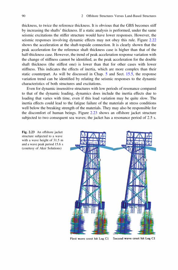
Even for dynamic insensitive structures with low periods of resonance comparedto that of the dynamic loading, dynamics does include the inertia effects due toloading that varies with time, even if this load variation may be quite slow. Theinertia effects could lead to the fatigue failure of the materials at stress conditionswell below the breaking strength of the materials. They may also be responsible forthe discomfort of human beings. Figure 2.23 shows an offshore jacket structuresubjected to two consequent sea waves; the jacket has a resonance period of 2.5 s.
Fig. 2.23 An offshore jacketstructure subjected to a wavewith a wave height of 31.5 mand a wave peak period 15.6 s(courtesy of Aker Solutions)
90 2 Offshore Structures Versus Land-Based Structures
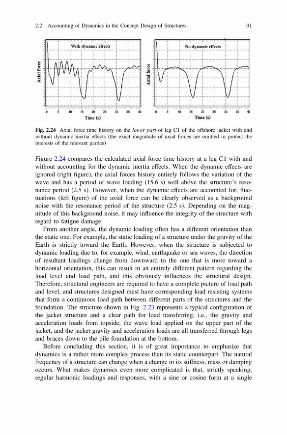
Figure 2.24 compares the calculated axial force time history at a leg C1 with andwithout accounting for the dynamic inertia effects. When the dynamic effects areignored (right figure), the axial forces history entirely follows the variation of thewave and has a period of wave loading (15.6 s) well above the structure’s reso-nance period (2.5 s). However, when the dynamic effects are accounted for, fluc-tuations (left figure) of the axial force can be clearly observed as a backgroundnoise with the resonance period of the structure (2.5 s). Depending on the mag-nitude of this background noise, it may influence the integrity of the structure withregard to fatigue damage.
From another angle, the dynamic loading often has a different orientation thanthe static one. For example, the static loading of a structure under the gravity of theEarth is strictly toward the Earth. However, when the structure is subjected todynamic loading due to, for example, wind, earthquake or sea waves, the directionof resultant loadings change from downward to the one that is more toward ahorizontal orientation, this can result in an entirely different pattern regarding theload level and load path, and this obviously influences the structural design.Therefore, structural engineers are required to have a complete picture of load pathand level, and structures designed must have corresponding load resisting systemsthat form a continuous load path between different parts of the structures and thefoundation. The structure shown in Fig. 2.23 represents a typical configuration ofthe jacket structure and a clear path for load transferring, i.e., the gravity andacceleration loads from topside, the wave load applied on the upper part of thejacket, and the jacket gravity and acceleration loads are all transferred through legsand braces down to the pile foundation at the bottom.
Before concluding this section, it is of great importance to emphasize thatdynamics is a rather more complex process than its static counterpart. The naturalfrequency of a structure can change when a change in its stiffness, mass or dampingoccurs. What makes dynamics even more complicated is that, strictly speaking,regular harmonic loadings and responses, with a sine or cosine form at a single
Fig. 2.24 Axial force time history on the lower part of leg C1 of the offshore jacket with andwithout dynamic inertia effects (the exact magnitude of axial forces are omitted to protect theinterests of the relevant parties)
2.2 Accounting of Dynamics in the Concept Design of Structures 91
frequency, do not represent environmental loadings (such as earthquake loadings)and the associated responses in the real world, even if they can be a good sim-plification when the dynamics at a single frequency is dominating. This implies thatone should always assess whether the vibrations in various frequencies need to beaccounted for or not.
2.2.2 Characteristics of Dynamic Responses
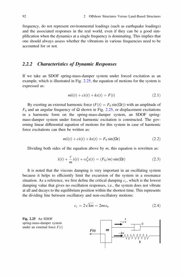
If we take an SDOF spring-mass-damper system under forced excitation as anexample, which is illustrated in Fig. 2.25, the equation of motions for the system isexpressed as:
m€xðtÞþ c _xðtÞþ kxðtÞ ¼ FðtÞ ð2:1Þ
By exerting an external harmonic force (FðtÞ ¼ F0 sinðXtÞ) with an amplitude ofF0 and an angular frequency of Ω shown in Fig. 2.25, or displacement excitationsin a harmonic form on the spring-mass-damper system, an SDOF spring-mass-damper system under forced harmonic excitation is constructed. The gov-erning linear differential equation of motions for this system in case of harmonicforce excitations can then be written as:
m€xðtÞþ c _xðtÞþ kxðtÞ ¼ F0 sinðXtÞ ð2:2Þ
Dividing both sides of the equation above by m, this equation is rewritten as:
€xðtÞþ cm_xðtÞþx2
nxðtÞ ¼ ðF0=mÞ sinðXtÞ ð2:3Þ
It is noted that the viscous damping is very important in an oscillating systembecause it helps to efficiently limit the excursion of the system in a resonancesituation. As a reference, we first define the critical damping cc, which is the lowestdamping value that gives no oscillation responses, i.e., the system does not vibrateat all and decays to the equilibrium position within the shortest time. This representsthe dividing line between oscillatory and non-oscillatory motions:
cc ¼ 2ffiffiffiffiffiffikm
p¼ 2mxn ð2:4Þ
- kx
c•
− xc
k
F(t) m
Fig. 2.25 An SDOFspring-mass-damper systemunder an external force FðtÞ
92 2 Offshore Structures Versus Land-Based Structures
The actual damping ratio can be specified as a percentage of critical damping:
f ¼ ccc
ð2:5Þ
By realizing that c ¼ 2xnmf, the equation of motions for the system finallygives:
€xðtÞþ 2xnf _xðtÞþx2nxðtÞ ¼ ðF0=mÞ sinðXtÞ ð2:6Þ
As the equation above is a second-order non-homogeneous equation, the generalsolution for it is the sum of the two parts: the complementary solution xcðtÞ to thehomogeneous (free vibrations) equation and the particular solution xpðtÞ to thenon-homogeneous equation:
xðtÞ ¼ xcðtÞþ xpðtÞ ð2:7Þ
The complementary solution exhibits transient vibrations at the system’s naturalfrequency and only depends on the initial condition and the system’s natural fre-quency, i.e., it represents free vibrations and does not contain any enforced responses:
xcðtÞ ¼ Xe�fxnt sinffiffiffiffiffiffiffiffiffiffiffiffiffi1� f2
qxntþ/
� �ð2:8Þ
It is noticed that this aspect of the vibration dies out due to the presence ofdamping, leaving only the particular solution exhibiting steady-state harmonicoscillation at excitation frequency Ω. This particular solution is also called thesteady-state solution that depends on the excitation amplitude F0, the excitationfrequency Ω as well as the natural frequency of the system, and it persists motionsfor ever:
xpðtÞ ¼ E sinðXtÞþF cosðXtÞ ð2:9Þ
By substituting the equation above and its first and second derivatives intoEq. (2.6), one obtains the coefficients E and F as:
E ¼ F0
k1� ðX=xnÞ2
1� ðX=xnÞ2h i2
þ 2fðX=xnÞ½ �2ð2:10Þ
F ¼ F0
k�2fX=xn
1� ðX=xnÞ2h i2
þ 2fðX=xnÞ½ �2ð2:11Þ
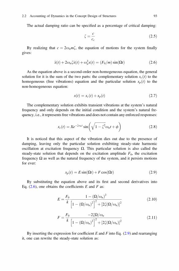
By inserting the expression for coefficient E and F into Eq. (2.9) and rearrangingit, one can rewrite the steady-state solution as:
2.2 Accounting of Dynamics in the Concept Design of Structures 93
xpðtÞ ¼ F0
kmsinðXt � uÞffiffiffiffiffiffiffiffiffiffiffiffiffiffiffiffiffiffiffiffiffiffiffiffiffiffiffiffiffiffiffiffiffiffiffiffiffiffiffiffiffiffiffiffiffiffiffiffiffiffiffiffiffiffiffiffiffiffiffiffiffi
1� ðX=xnÞ2h i2
þ 2fðX=xnÞ½ �2r ð2:12Þ
where u is the phase between the external input force and the response output, withthe most noticeable feature being a shift (particularly for underdamped systems) atresonance. It can be calculated as:
u ¼ tan�1 2fðX=xnÞ1� ðX=xnÞ2
!ð2:13Þ
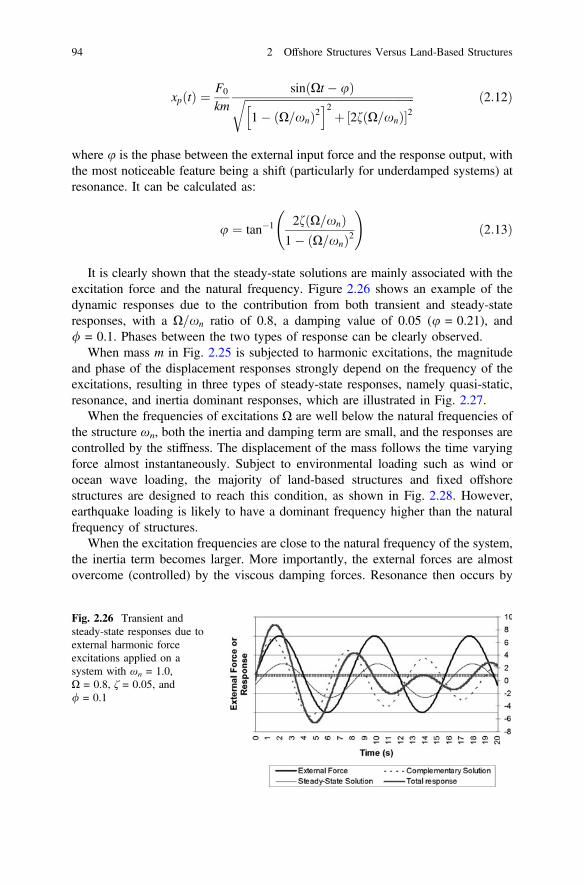
It is clearly shown that the steady-state solutions are mainly associated with theexcitation force and the natural frequency. Figure 2.26 shows an example of thedynamic responses due to the contribution from both transient and steady-stateresponses, with a X=xn ratio of 0.8, a damping value of 0.05 (u = 0.21), and/ = 0.1. Phases between the two types of response can be clearly observed.
When mass m in Fig. 2.25 is subjected to harmonic excitations, the magnitudeand phase of the displacement responses strongly depend on the frequency of theexcitations, resulting in three types of steady-state responses, namely quasi-static,resonance, and inertia dominant responses, which are illustrated in Fig. 2.27.
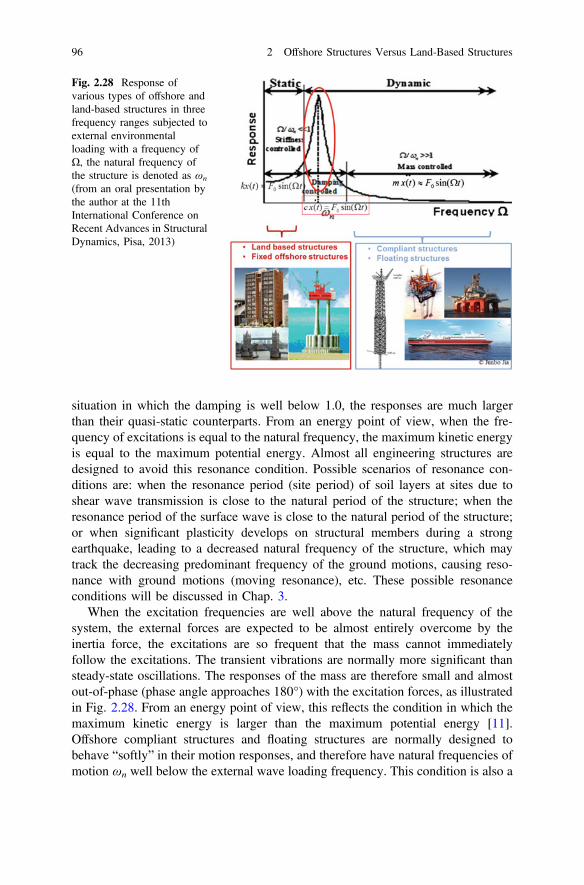
When the frequencies of excitations Ω are well below the natural frequencies ofthe structure ωn, both the inertia and damping term are small, and the responses arecontrolled by the stiffness. The displacement of the mass follows the time varyingforce almost instantaneously. Subject to environmental loading such as wind orocean wave loading, the majority of land-based structures and fixed offshorestructures are designed to reach this condition, as shown in Fig. 2.28. However,earthquake loading is likely to have a dominant frequency higher than the naturalfrequency of structures.
When the excitation frequencies are close to the natural frequency of the system,the inertia term becomes larger. More importantly, the external forces are almostovercome (controlled) by the viscous damping forces. Resonance then occurs by
Fig. 2.26 Transient andsteady-state responses due toexternal harmonic forceexcitations applied on asystem with ωn = 1.0,X = 0.8, ζ = 0.05, and/ = 0.1
94 2 Offshore Structures Versus Land-Based Structures
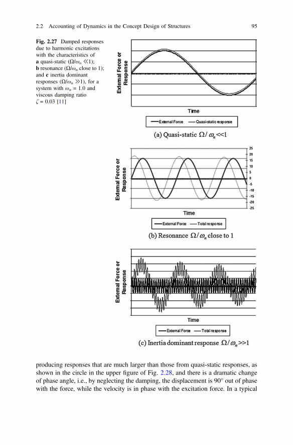
producing responses that are much larger than those from quasi-static responses, asshown in the circle in the upper figure of Fig. 2.28, and there is a dramatic changeof phase angle, i.e., by neglecting the damping, the displacement is 90° out of phasewith the force, while the velocity is in phase with the excitation force. In a typical
Fig. 2.27 Damped responsesdue to harmonic excitationswith the characteristics ofa quasi-static (Ω/ωn ≪1);b resonance (Ω/ωn close to 1);and c inertia dominantresponses (Ω/ωn ≫1), for asystem with ωn = 1.0 andviscous damping ratioζ = 0.03 [11]
2.2 Accounting of Dynamics in the Concept Design of Structures 95
situation in which the damping is well below 1.0, the responses are much largerthan their quasi-static counterparts. From an energy point of view, when the fre-quency of excitations is equal to the natural frequency, the maximum kinetic energyis equal to the maximum potential energy. Almost all engineering structures aredesigned to avoid this resonance condition. Possible scenarios of resonance con-ditions are: when the resonance period (site period) of soil layers at sites due toshear wave transmission is close to the natural period of the structure; when theresonance period of the surface wave is close to the natural period of the structure;or when significant plasticity develops on structural members during a strongearthquake, leading to a decreased natural frequency of the structure, which maytrack the decreasing predominant frequency of the ground motions, causing reso-nance with ground motions (moving resonance), etc. These possible resonanceconditions will be discussed in Chap. 3.
When the excitation frequencies are well above the natural frequency of thesystem, the external forces are expected to be almost entirely overcome by theinertia force, the excitations are so frequent that the mass cannot immediatelyfollow the excitations. The transient vibrations are normally more significant thansteady-state oscillations. The responses of the mass are therefore small and almostout-of-phase (phase angle approaches 180°) with the excitation forces, as illustratedin Fig. 2.28. From an energy point of view, this reflects the condition in which themaximum kinetic energy is larger than the maximum potential energy [11].Offshore compliant structures and floating structures are normally designed tobehave “softly” in their motion responses, and therefore have natural frequencies ofmotion ωn well below the external wave loading frequency. This condition is also a
Fig. 2.28 Response ofvarious types of offshore andland-based structures in threefrequency ranges subjected toexternal environmentalloading with a frequency ofΩ, the natural frequency ofthe structure is denoted as ωn
(from an oral presentation bythe author at the 11thInternational Conference onRecent Advances in StructuralDynamics, Pisa, 2013)
96 2 Offshore Structures Versus Land-Based Structures
most usual scenario encountered during an earthquake event. It is noted that formost of the engineering structures and typical site conditions, the long period ofseismic ground excitations are usually small, except for the ground motions causedby the seismic surface (Rayleigh) waves, which can have dominating long periodcomponents of ground motions, which will be presented in Chap. 3. Therefore,subject to seismic ground excitations, a large amount of offshore and land-basedstructures are likely to reach this condition.
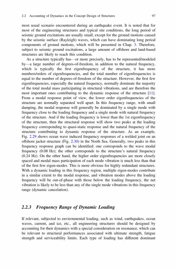
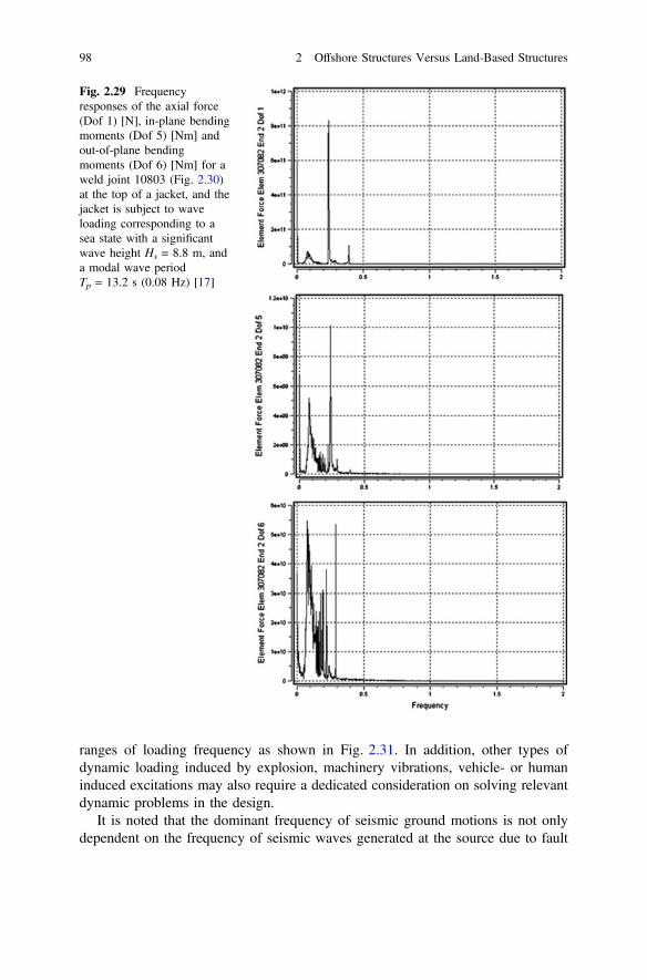
As a structure typically has—or more precisely, has to be represented/modeledby—a large number of degrees-of-freedom, in addition to the natural frequency,which is typically the first eigenfrequency of the structure, it has morenumbers/orders of eigenfrequencies, and the total number of eigenfrequencies isequal to the number of degrees-of-freedom of the structure. However, the first feweigenfrequencies, especially the natural frequency, normally dominate the majorityof the total modal mass participating in structural vibrations, and are therefore themost important ones contributing to the dynamic response of the structure [11].From a modal response point of view, the lower order eigenfrequencies of thestructure are normally separated well apart. In this frequency range, with smalldamping, the modal response will generally be dominated by a single mode withfrequency close to the loading frequency and a single mode with natural frequencyof the structure. And if the loading frequency is lower than the 1st eigenfrequencyof the structure, then the structural response will show two peaks at the loadingfrequency corresponding to quasi-static response and the natural frequency of thestructure contributing to dynamic response of the structure. As an example,Fig. 2.29 shows ocean wave induced frequency responses of a welded joint on anoffshore jacket structure (Fig. 2.30) in the North Sea. Generally, two peaks in thisfrequency response graph can be identified: one corresponds to the wave modalfrequency (0.08 Hz); the other corresponds to the structure’s natural frequency(0.24 Hz). On the other hand, the higher order eigenfrequencies are more closelyspaced and modal mass participation of each mode vibration is much less than thatof the first few eigen-modes. This is more obvious for highly redundant structures.With a dynamic loading in this frequency region, multiple eigen-modes contributein a similar extent to the modal response, and vibration modes above the loadingfrequency will be out-of-phase with those below the loading frequency, the netvibration is likely to be less than any of the single mode vibrations in this frequencyrange (dynamic cancelation).
2.2.3 Frequency Range of Dynamic Loading
If relevant, subjected to environmental loading, such as wind, earthquakes, oceanwaves, current, and ice, etc., all engineering structures should be designed byaccounting for their dynamics with a special consideration on resonance, which canbe relevant to structural performances associated with ultimate strength, fatiguestrength and serviceability limits. Each type of loading has different dominant
2.2 Accounting of Dynamics in the Concept Design of Structures 97
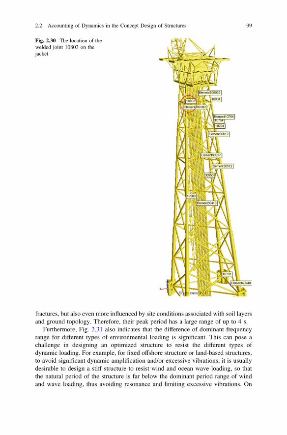
ranges of loading frequency as shown in Fig. 2.31. In addition, other types ofdynamic loading induced by explosion, machinery vibrations, vehicle- or humaninduced excitations may also require a dedicated consideration on solving relevantdynamic problems in the design.
It is noted that the dominant frequency of seismic ground motions is not onlydependent on the frequency of seismic waves generated at the source due to fault
Fig. 2.29 Frequencyresponses of the axial force(Dof 1) [N], in-plane bendingmoments (Dof 5) [Nm] andout-of-plane bendingmoments (Dof 6) [Nm] for aweld joint 10803 (Fig. 2.30)at the top of a jacket, and thejacket is subject to waveloading corresponding to asea state with a significantwave height Hs = 8.8 m, anda modal wave periodTp = 13.2 s (0.08 Hz) [17]
98 2 Offshore Structures Versus Land-Based Structures
fractures, but also even more influenced by site conditions associated with soil layersand ground topology. Therefore, their peak period has a large range of up to 4 s.
Furthermore, Fig. 2.31 also indicates that the difference of dominant frequencyrange for different types of environmental loading is significant. This can pose achallenge in designing an optimized structure to resist the different types ofdynamic loading. For example, for fixed offshore structure or land-based structures,to avoid significant dynamic amplification and/or excessive vibrations, it is usuallydesirable to design a stiff structure to resist wind and ocean wave loading, so thatthe natural period of the structure is far below the dominant period range of windand wave loading, thus avoiding resonance and limiting excessive vibrations. On
Fig. 2.30 The location of thewelded joint 10803 on thejacket
2.2 Accounting of Dynamics in the Concept Design of Structures 99
the other hand, the low dominant period of seismic loading requires a “softer”structure design that cherishes a higher natural period. This contradiction has beenencountered in various structural design projects. Sometimes a “balance” betweenthe two needs to be sought, such as the design of Taipei 101. It has a natural periodof around 7 s, which is obviously above the dominant period of earthquake loading.Even though this natural period of 7 s is also far below the period of loading due towind turbulence (fluctuating part of wind), it can induce significant peak acceler-ation at the top of Taipei 101, causing both human discomfort and structural metalfatigue. To solve this problem, a large tuned mass damper (TMD) weighing 660 t(Fig. 2.32), as will be discussed in Chap. 24, was introduced to mitigate swaymotion of the building, particularly in major typhoons or earthquakes wheremovement of the top floor can exceed 1.5 m. The TMD will reduce peak accel-eration of the top occupied floor from 7.9 to 5.0 mg due to wind storm with a returnperiod of half year. For a 1000–2500 year return period of strong earthquake, theTMD will be rather effective to mitigate the dynamic response of the structure, and
Fig. 2.31 Typical short term environmental loading frequency/period (from an oral presentationby the author at the 11th International Conference on Recent Advances in Structural Dynamics,Pisa, 2013)
100 2 Offshore Structures Versus Land-Based Structures
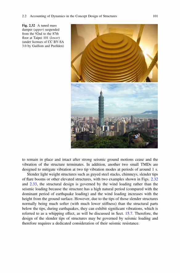
to remain in place and intact after strong seismic ground motions cease and thevibration of the structure terminates. In addition, another two small TMDs aredesigned to mitigate vibration at two tip vibration modes at periods of around 1 s.
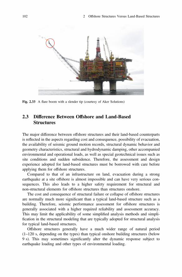
Slender light weight structures such as guyed steel stacks, chimneys, slender tipsof flare booms or other elevated structures, with two examples shown in Figs. 2.32and 2.33, the structural design is governed by the wind loading rather than theseismic loading because the structure has a high natural period (compared with thedominant period of earthquake loading) and the wind loading increases with theheight from the ground surface. However, due to the tips of those slender structuresnormally being much softer (with much lower stiffness) than the structural partsbelow the tips, during earthquakes, they can exhibit significant vibrations, which isreferred to as a whipping effect, as will be discussed in Sect. 15.7. Therefore, thedesign of the slender tips of structures may be governed by seismic loading andtherefore requires a dedicated consideration of their seismic resistance.
Fig. 2.32 A tuned massdamper (upper) suspendedfrom the 92nd to the 87thfloor at Taipei 101 (lower)(under licenses of CC BY-SA3.0 by Guillom and Peellden)
2.2 Accounting of Dynamics in the Concept Design of Structures 101
2.3 Difference Between Offshore and Land-BasedStructures
The major difference between offshore structures and their land-based counterpartsis reflected in the aspects regarding cost and consequence, possibility of evacuation,the availability of seismic ground motion records, structural dynamic behavior andgeometry characteristics, structural and hydrodynamic damping, other accompaniedenvironmental and operational loads, as well as special geotechnical issues such assite conditions and sudden subsidence. Therefore, the assessment and designexperience adopted for land-based structures must be borrowed with care beforeapplying them for offshore structures.
Compared to that of an infrastructure on land, evacuation during a strongearthquake at a site offshore is almost impossible and can have very serious con-sequences. This also leads to a higher safety requirement for structural andnon-structural elements for offshore structures than structures onshore.
The cost and consequence of structural failure or collapse of offshore structuresare normally much more significant than a typical land-based structure such as abuilding. Therefore, seismic performance assessment for offshore structures isgenerally associated with a higher required reliability and assessment accuracy.This may limit the applicability of some simplified analysis methods and simpli-fication in the structural modeling that are typically adopted for structural analysisfor typical land-based structures.
Offshore structures generally have a much wider range of natural period(1–120 s, depending on the types) than typical onshore building structures (below9 s). This may sometimes significantly alter the dynamic response subject toearthquake loading and other types of environmental loading.
Fig. 2.33 A flare boom with a slender tip (courtesy of Aker Solutions)
102 2 Offshore Structures Versus Land-Based Structures
Due to the significant environmental loading mainly induced by ocean waves,offshore structures are generally much larger in plan than most buildings but do nothave a common foundation form to resist the overturning moment generated by thewave and other environmental loads. Hence, subjected to seismic or ocean waveloading, offshore structures are more likely to exhibit a combined torsion andbending (translation) response [12].
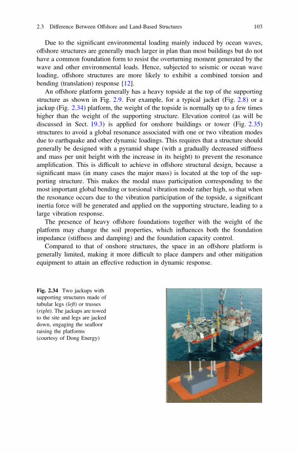
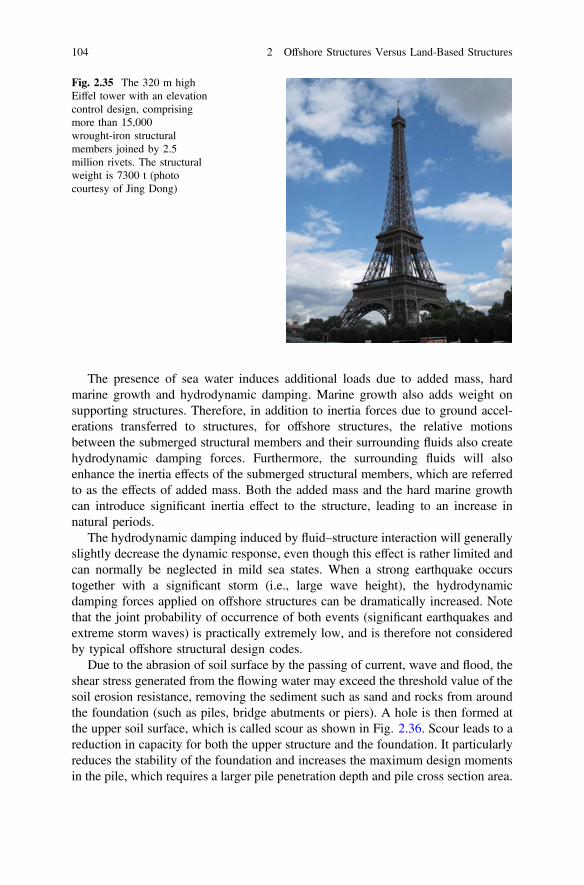
An offshore platform generally has a heavy topside at the top of the supportingstructure as shown in Fig. 2.9. For example, for a typical jacket (Fig. 2.8) or ajackup (Fig. 2.34) platform, the weight of the topside is normally up to a few timeshigher than the weight of the supporting structure. Elevation control (as will bediscussed in Sect. 19.3) is applied for onshore buildings or tower (Fig. 2.35)structures to avoid a global resonance associated with one or two vibration modesdue to earthquake and other dynamic loadings. This requires that a structure shouldgenerally be designed with a pyramid shape (with a gradually decreased stiffnessand mass per unit height with the increase in its height) to prevent the resonanceamplification. This is difficult to achieve in offshore structural design, because asignificant mass (in many cases the major mass) is located at the top of the sup-porting structure. This makes the modal mass participation corresponding to themost important global bending or torsional vibration mode rather high, so that whenthe resonance occurs due to the vibration participation of the topside, a significantinertia force will be generated and applied on the supporting structure, leading to alarge vibration response.
The presence of heavy offshore foundations together with the weight of theplatform may change the soil properties, which influences both the foundationimpedance (stiffness and damping) and the foundation capacity control.
Compared to that of onshore structures, the space in an offshore platform isgenerally limited, making it more difficult to place dampers and other mitigationequipment to attain an effective reduction in dynamic response.
Fig. 2.34 Two jackups withsupporting structures made oftubular legs (left) or trusses(right). The jackups are towedto the site and legs are jackeddown, engaging the seafloorraising the platforms(courtesy of Dong Energy)
2.3 Difference Between Offshore and Land-Based Structures 103
The presence of sea water induces additional loads due to added mass, hardmarine growth and hydrodynamic damping. Marine growth also adds weight onsupporting structures. Therefore, in addition to inertia forces due to ground accel-erations transferred to structures, for offshore structures, the relative motionsbetween the submerged structural members and their surrounding fluids also createhydrodynamic damping forces. Furthermore, the surrounding fluids will alsoenhance the inertia effects of the submerged structural members, which are referredto as the effects of added mass. Both the added mass and the hard marine growthcan introduce significant inertia effect to the structure, leading to an increase innatural periods.
The hydrodynamic damping induced by fluid–structure interaction will generallyslightly decrease the dynamic response, even though this effect is rather limited andcan normally be neglected in mild sea states. When a strong earthquake occurstogether with a significant storm (i.e., large wave height), the hydrodynamicdamping forces applied on offshore structures can be dramatically increased. Notethat the joint probability of occurrence of both events (significant earthquakes andextreme storm waves) is practically extremely low, and is therefore not consideredby typical offshore structural design codes.
Due to the abrasion of soil surface by the passing of current, wave and flood, theshear stress generated from the flowing water may exceed the threshold value of thesoil erosion resistance, removing the sediment such as sand and rocks from aroundthe foundation (such as piles, bridge abutments or piers). A hole is then formed atthe upper soil surface, which is called scour as shown in Fig. 2.36. Scour leads to areduction in capacity for both the upper structure and the foundation. It particularlyreduces the stability of the foundation and increases the maximum design momentsin the pile, which requires a larger pile penetration depth and pile cross section area.
Fig. 2.35 The 320 m highEiffel tower with an elevationcontrol design, comprisingmore than 15,000wrought-iron structuralmembers joined by 2.5million rivets. The structuralweight is 7300 t (photocourtesy of Jing Dong)
104 2 Offshore Structures Versus Land-Based Structures
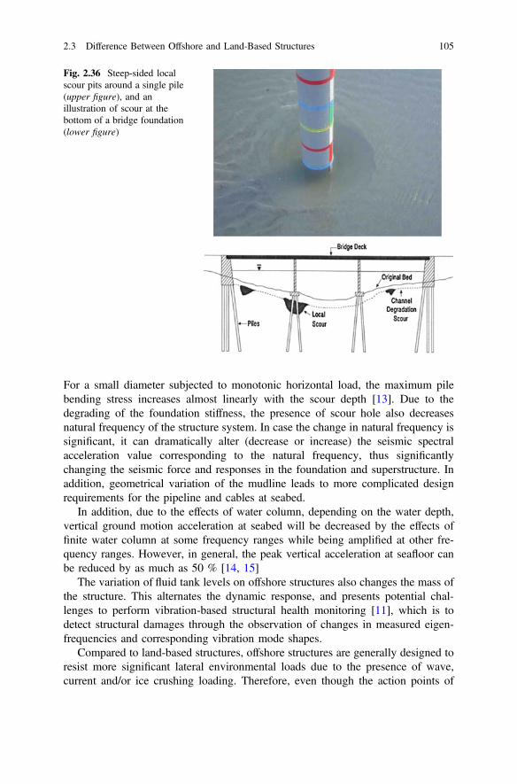
For a small diameter subjected to monotonic horizontal load, the maximum pilebending stress increases almost linearly with the scour depth [13]. Due to thedegrading of the foundation stiffness, the presence of scour hole also decreasesnatural frequency of the structure system. In case the change in natural frequency issignificant, it can dramatically alter (decrease or increase) the seismic spectralacceleration value corresponding to the natural frequency, thus significantlychanging the seismic force and responses in the foundation and superstructure. Inaddition, geometrical variation of the mudline leads to more complicated designrequirements for the pipeline and cables at seabed.
In addition, due to the effects of water column, depending on the water depth,vertical ground motion acceleration at seabed will be decreased by the effects offinite water column at some frequency ranges while being amplified at other fre-quency ranges. However, in general, the peak vertical acceleration at seafloor canbe reduced by as much as 50 % [14, 15]
The variation of fluid tank levels on offshore structures also changes the mass ofthe structure. This alternates the dynamic response, and presents potential chal-lenges to perform vibration-based structural health monitoring [11], which is todetect structural damages through the observation of changes in measured eigen-frequencies and corresponding vibration mode shapes.
Compared to land-based structures, offshore structures are generally designed toresist more significant lateral environmental loads due to the presence of wave,current and/or ice crushing loading. Therefore, even though the action points of
Fig. 2.36 Steep-sided localscour pits around a single pile(upper figure), and anillustration of scour at thebottom of a bridge foundation(lower figure)
2.3 Difference Between Offshore and Land-Based Structures 105
those loadings on structures may be far from that of the earthquake induced groundexcitations, the seismic performance of offshore structures are normally better thantheir land-based counterparts.
Finally, but not the least consideration, as a consequence of a special type ofearthquake, the sudden subsidence of offshore platforms, as will be elaborated inChap. 16, has been realized to be a serious risk by more and more energy com-panies as well as authority bodies, which needs consideration during the design.
References
1. Chakrabarti S (ed) (2005) Handbook of offshore structures. Elsevier, Oxford2. Gerwick BCJ (1986) Construction of offshore structures. Wiley, New York3. Reddy DV, Arockiasamy M (1991) Offshore structures. Krieger Publishing Company,
Malabar4. Clauss G et al (1992) Offshore structures. Conceptual design and hydromechanics (translated
by MJ Shields), vol 1. Springer, Berlin5. Jia J (2016) Soil dynamics and foundation modeling: offshore and earthquake engineering.
Springer, Heidelberg6. Chandrasekaran S (2015) Advanced marine structures. CRC Press, Boca Raton7. Pike J (2011) Compliant tower. http://www.globalsecurity.org/military/systems/ship/platform-
compliant-tower.htm8. Chakrabarti S (2008) Challenges for a total system analysis on deepwater floating systems.
Open Mech J 2:28–469. van Wijngaarden M (2013) Concept design of steel bottom founded support structures for
offshore wind turbines. Delft University of Technology10. Naess A, Moan T (2012) Stochastic dynamics of marine structures. Cambridge University
Press, Cambridge11. Jia J (2014) Essentials of applied dynamic analysis. Springer, Heidelberg12. Sharpe RL, Newmark NM (1977) Extending seismic design provisions for buildings to the
design of offshore structures. Offshore technology conference, Houston, Texas, May 197713. Diamantidis D, Arnesen K (1986) Scour effects in piled structures: a sensitivity analysis.
Ocean Eng 13:497–50214. Smith CE (1997) Dynamic response of steel-jacket platform subject to measured seafloor
earthquake ground motions. In: Proceedings 8th international conference on the behaviour ofoffshore structures, BOSS’97, vol 3. Delft: Pergamon, Elsevier Science Ltd., Oxford, England
15. Sleefe GE (1990) The long-term measurement of strong-motion earthquakes offshore SouthCalifornia. In: Proceedings of OTC 1990, society of petroleum engineers, Richardson, Texas
16. Kuo YS, Abdel Rahman K, Wu KT, Huang TY, Achmus M (2014) Suitability of a pile groupfoundation for an offshore wind turbine. In: Proceedings of the 24th international ocean andpolar engineering conference, Busan
17. Jia J (2016) The effect of gravity on the dynamic characteristics and fatigue life assessment ofoffshore structures. J Constr Steel Res 118(1):1–21
106 2 Offshore Structures Versus Land-Based Structures

http://www.springer.com/978-3-642-31853-5