wave theory offshore structures
DESCRIPTION
Wave Theory Offshore StructuresTRANSCRIPT
Offshore Engineering and Technology
Day1AM 1
THREE DAY SHORT COURSE
Course Presentation
An introduction on
Offshore Engineering and Technology
INSTRUCTOR: DR. SUBRATA K. CHAKRABARTI
University of Illinois at Chicago Offshore Structure Analysis Inc.
Plainfield, ILLINOIS
Offshore Engineering and Technology
Day1AM 2
Offshore Engineering and Technology
Overview of the 3-Day Course
COURSE OUTLINE
---------- DAY 1 ----------
Morning Afternoon
Introduction to Design Environment &Construction: • History and current state of the art • Offshore environment • Design cycle of offshore structures • Construction and launching • Preliminary concept design
---------- DAY 2 ----------
Morning Afternoon
Design Tools and Evaluation Design Tools and Evaluation
• static and dynamic stability • structure response and sea-keeping • environmental forces
---------- DAY 3 ----------
Morning Afternoon
Design Tools and Evaluation Design validation and model testing
• probabilistic design • riser system • extreme load & strength & fatigue • Scaling laws & Model testing • anchoring and mooring system • Challenges in deepwater testing • Assessment of validation methods
Offshore Engineering and Technology
Day1AM 3
History and current state of the art of offshore structures Definition of Offshore Structures
No fixed access to dry land May be required to stay in position in all weather conditions
Functions of Offshore Structures
♦ Exploratory Drilling Structures: A Mobile Offshore Drilling Unit [MODU] configuration is largely determined by the variable deck payload and transit speed requirements.
♦ Production Structures: A production unit can have several functions, e.g. processing, drilling, workover, accommodation, oil storage and riser support.
♦ Storage Structures: Stores the crude oil temporarily at the offshore site before its transportation to the shore for processing.
Offshore Engineering and Technology
Day1AM 4
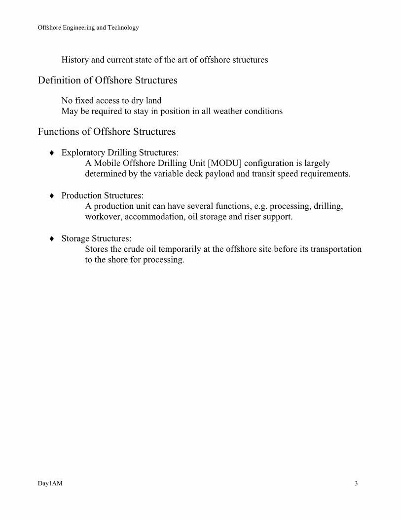
Types of Offshore structures
Fulmar jacket platform
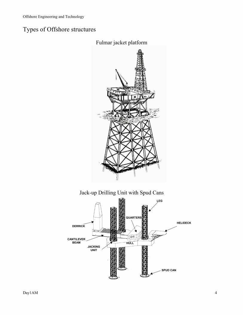
Jack-up Drilling Unit with Spud Cans
DERRICKHELIDECK
SPUD CAN
LEG
CANTILEVERBEAM
QUARTERS
JACKINGUNIT
HULL

Offshore Engineering and Technology
Day1AM 5
Historical Development of Fixed Offshore Structures
Gravity Base Structures placed on the seafloor and held in place by their weight
Troll A gas platform, world's tallest concrete structure in North Sea

Offshore Engineering and Technology
Day1AM 6
Structures piled to the seabed
500,000 barrel oil storage gravity & piled structure in Persian Gulf
Compliant Tower
Deck
Fw (t)
Tower Frame
Ungrouted pilesliding inside thetower leg or pileguides
Pile top weldconnected tothe tower at top
Offshore Engineering and Technology
Day1AM 7
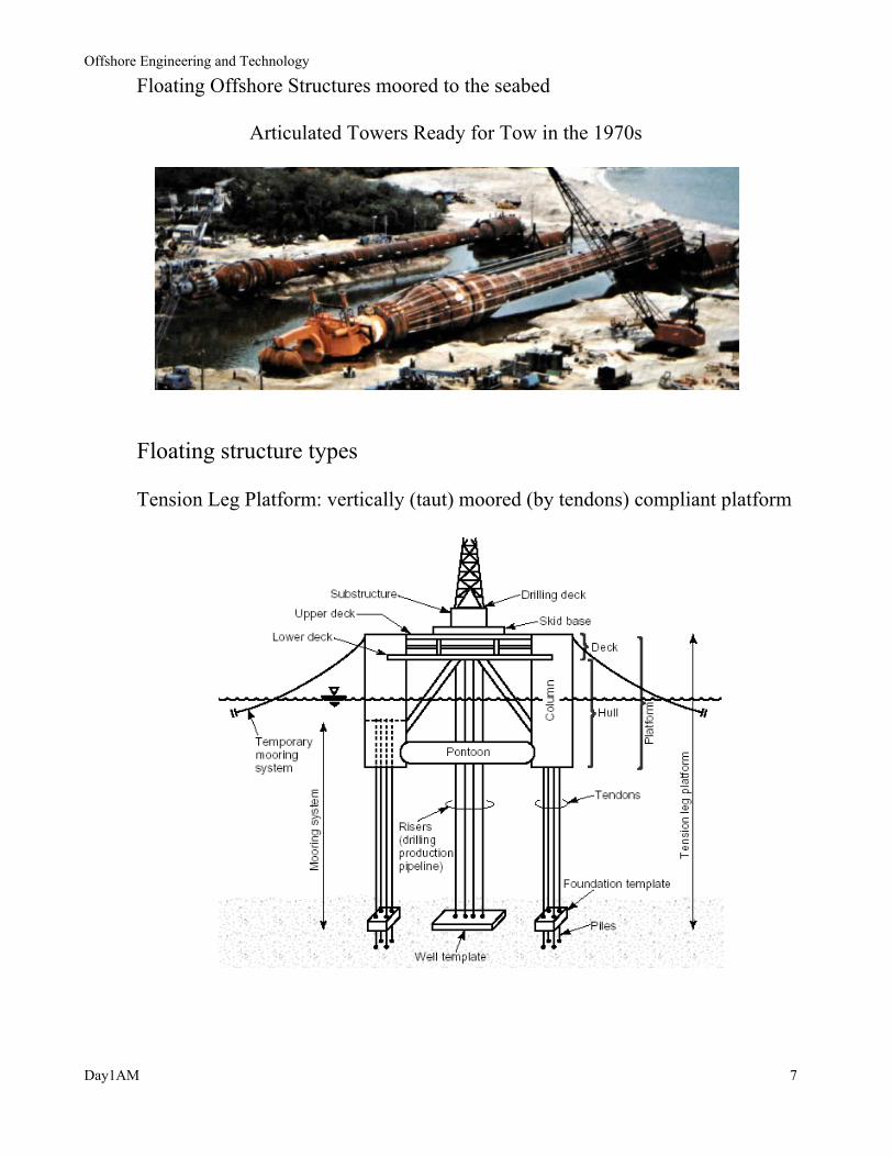
Floating Offshore Structures moored to the seabed
Articulated Towers Ready for Tow in the 1970s
Floating structure types Tension Leg Platform: vertically (taut) moored (by tendons) compliant platform

Offshore Engineering and Technology
Day1AM 8
Semisubmersible Platform: Semisubmersibles are multi-legged floating structures
Marine 7000 4th generation semi-submersible
Floating Production Storage and Offloading (FPSO) ship shaped with a turret
Balder: first "permanent" FPSO in the North Sea
Internal bow turret Cantilevered bow turret
Offshore Engineering and Technology
Day1AM 9
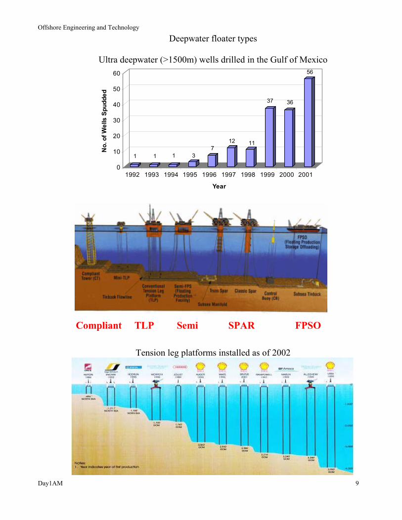
Deepwater floater types
Ultra deepwater (>1500m) wells drilled in the Gulf of Mexico
1 1 1 37
12 11
37 36
56
0
10
20
30
40
50
60
No.
of W
ells
Spu
dded
1992 1993 1994 1995 1996 1997 1998 1999 2000 2001
Year
Compliant TLP Semi SPAR FPSO
Tension leg platforms installed as of 2002

Offshore Engineering and Technology
Day1AM 10
Progression of Spars
5th generation drilling semi-submersible “Deepwater Nautilus”
SeaStar MiniTLP for Typhoon Field
Offshore Engineering and Technology
Day1AM 11
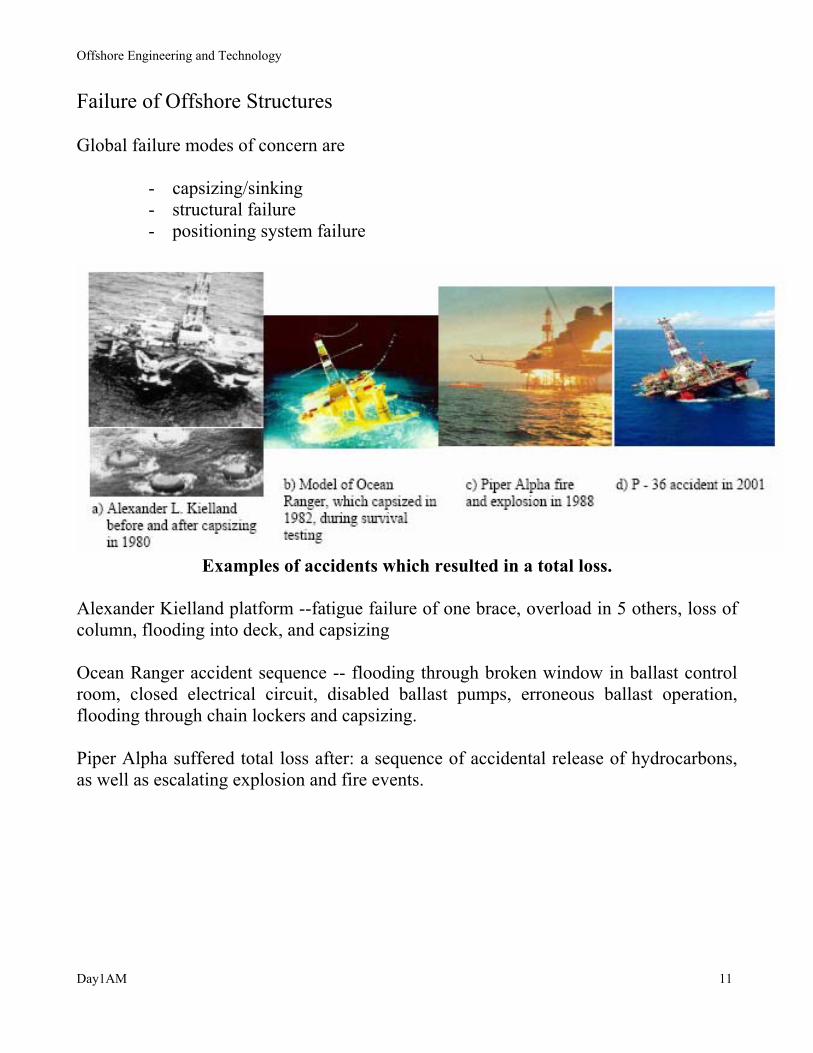
Failure of Offshore Structures Global failure modes of concern are
- capsizing/sinking - structural failure - positioning system failure
Examples of accidents which resulted in a total loss.
Alexander Kielland platform --fatigue failure of one brace, overload in 5 others, loss of column, flooding into deck, and capsizing Ocean Ranger accident sequence -- flooding through broken window in ballast control room, closed electrical circuit, disabled ballast pumps, erroneous ballast operation, flooding through chain lockers and capsizing. Piper Alpha suffered total loss after: a sequence of accidental release of hydrocarbons, as well as escalating explosion and fire events.
Offshore Engineering and Technology
Day1AM 12
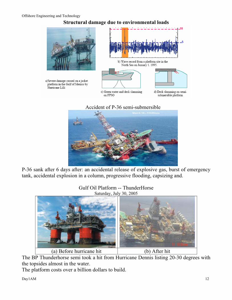
Structural damage due to environmental loads
Accident of P-36 semi-submersible
P-36 sank after 6 days after: an accidental release of explosive gas, burst of emergency tank, accidental explosion in a column, progressive flooding, capsizing and.
Gulf Oil Platform -- ThunderHorse Saturday, July 30, 2005
(a) Before hurricane hit (b) After hit The BP Thunderhorse semi took a hit from Hurricane Dennis listing 20-30 degrees with the topsides almost in the water. The platform costs over a billion dollars to build.
Offshore Engineering and Technology
Day1AM 13
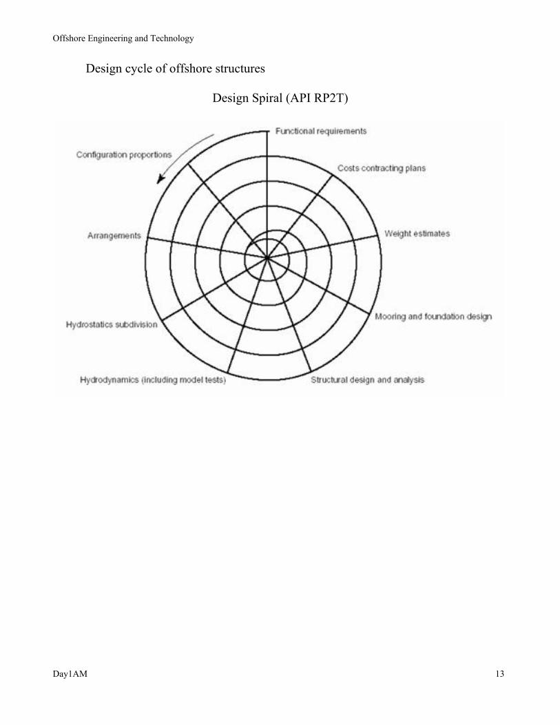
Design cycle of offshore structures
Design Spiral (API RP2T)
Offshore Engineering and Technology
Day1AM 14
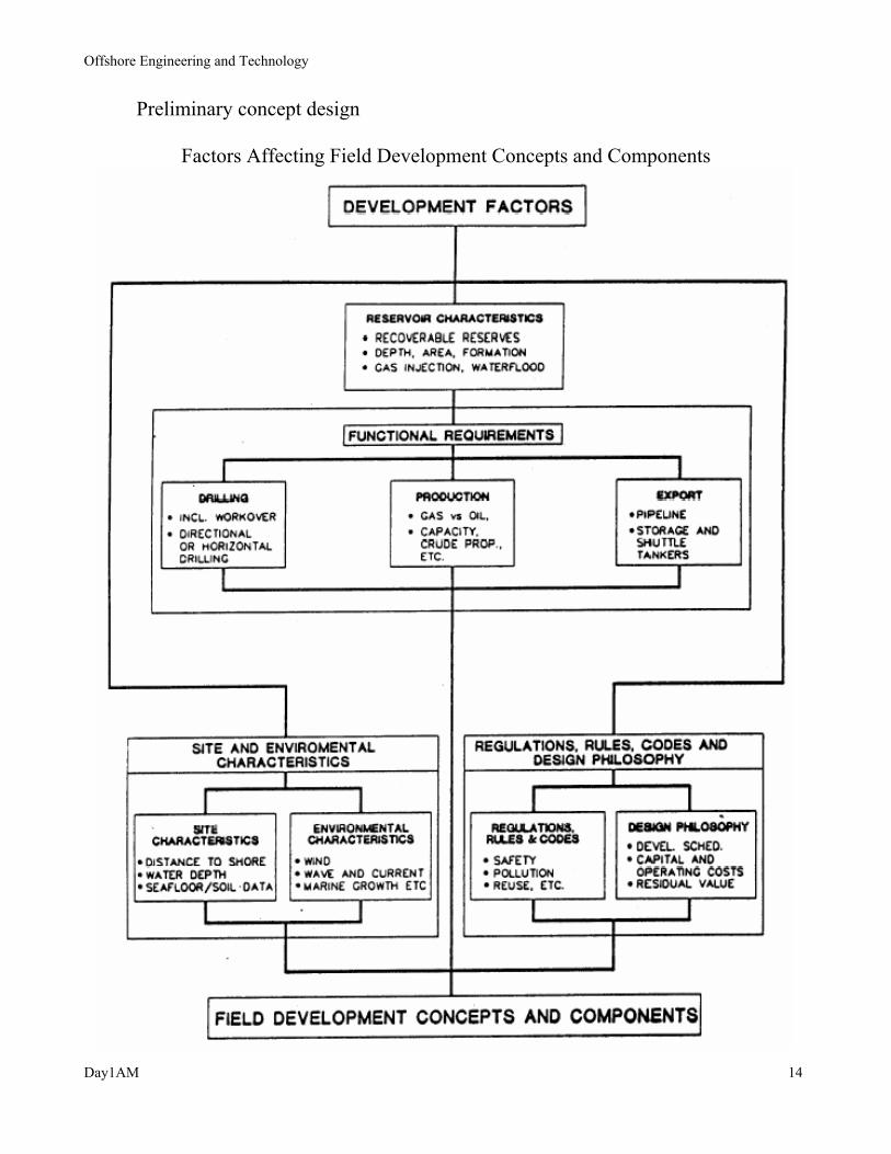
Preliminary concept design
Factors Affecting Field Development Concepts and Components
Offshore Engineering and Technology
Day1AM 15
Offshore environment
Offshore Engineering and Technology
Day1AM 16
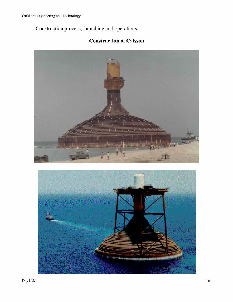
Construction process, launching and operations
Construction of Caisson

Offshore Engineering and Technology
Day1AM 17
Running Pile from Derrick Barge

Offshore Engineering and Technology
Day1AM 18
Construction of the Spar (Technip Offshore)
Seastar® fabrication, Louisiana (SBM Atlantia)
Offloading of Spar Hull for Transport (Dockwise)

Offshore Engineering and Technology
Day1AM 19
Truss Spar in Dry Tow
Holstein Spar being towed out of site
Brutus TLP

Offshore Engineering and Technology
Day1AM 20
Spar Upending Sequence (Kocaman et al, 1997)
Offshore Engineering and Technology
Day1AM 21
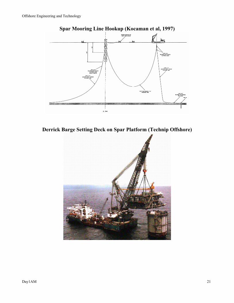
Spar Mooring Line Hookup (Kocaman et al, 1997)
Derrick Barge Setting Deck on Spar Platform (Technip Offshore)
Offshore Engineering and Technology
Day1AM 22
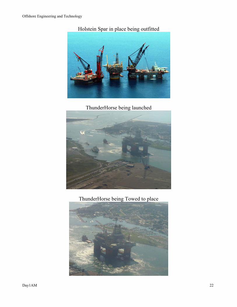
Holstein Spar in place being outfitted
ThunderHorse being launched
ThunderHorse being Towed to place

Offshore Engineering and Technology
Day1AM 23
Installation of the lower turret on FPSO Balder
APL Buoy Turret System
Offshore Engineering and Technology
Day1AM 24
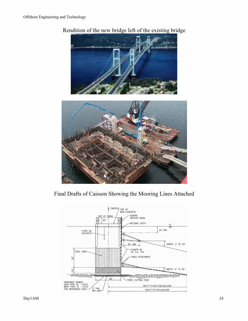
Rendition of the new bridge left of the existing bridge
Final Drafts of Caisson Showing the Mooring Lines Attached
Offshore Engineering and Technology
Day1AM 25
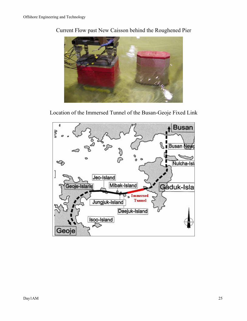
Current Flow past New Caisson behind the Roughened Pier
Location of the Immersed Tunnel of the Busan-Geoje Fixed Link

Offshore Engineering and Technology
Day1AM 26
Immersion of TE into trench
Physical Testing of Rigs Moored above the Trench

Offshore Engineering and Technology
Day1AM 27
OCEAN ENVIRONMENT
Standing Wave vs. Progressive Wave
Linear Theory (also called Stokes First Order, Airy)
Stokes Second Order Theory
Stokes Fifth Order Theory
Stream Function Theory
Measured Wave Properties in Wave Tank
Offshore Applications of Wave Theory
Current -- Uniform and Shear
Wave-current Interaction
Wind and Wind Spectrum
1NOTE: Chapter 3, Hydrodynamics of Offshore Structures

Offshore Engineering and Technology
Day1AM 28
Idealization of Waves
Actual Ocean Wave
Simple Idealizations to Regular Waves
Sine Wave
-1
0
1
0 90 180 270 360
Angle, deg.
Am
plitu
de
Nonlinear Regular Wave
-1.25
0.00
1.25
0 90 180 270 360
Angle, deg.
Am
plitu
de
Offshore Engineering and Technology
Day1AM 29
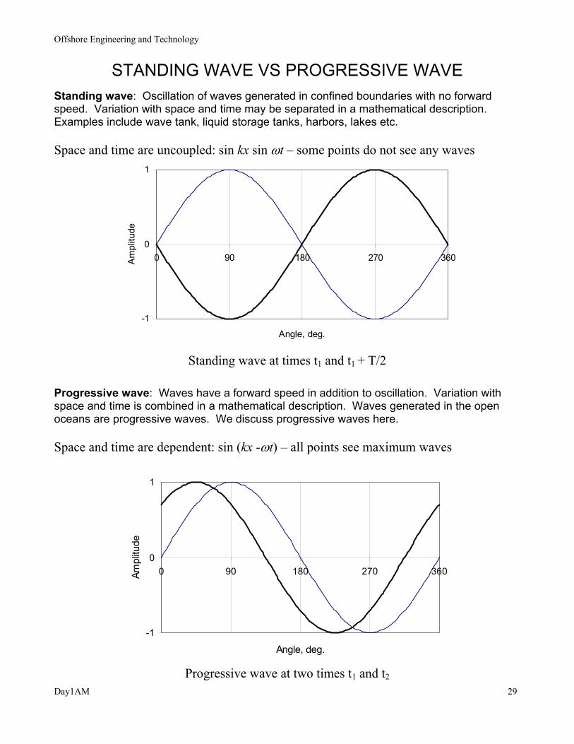
STANDING WAVE VS PROGRESSIVE WAVE
Standing wave: Oscillation of waves generated in confined boundaries with no forward speed. Variation with space and time may be separated in a mathematical description. Examples include wave tank, liquid storage tanks, harbors, lakes etc. Space and time are uncoupled: sin kx sin ωt – some points do not see any waves
-1
0
1
0 90 180 270 360
Angle, deg.
Am
plitu
de
Standing wave at times t1 and t1 + T/2
Progressive wave: Waves have a forward speed in addition to oscillation. Variation with space and time is combined in a mathematical description. Waves generated in the open oceans are progressive waves. We discuss progressive waves here. Space and time are dependent: sin (kx -ωt) – all points see maximum waves
-1
0
1
0 90 180 270 360
Angle, deg.
Ampl
itude
Progressive wave at two times t1 and t2

Offshore Engineering and Technology
Day1AM 30
WAVE THEORIES
Three Independent Parameters describe all waves so that they must
be specified for a wave. They are:
water depth, d
wave height, H
wave period, T
d: uniform water depth based on flat bottom
T: fixed interval of time at which a succession of wave crests
passes a given point
L: wave length i.e., length between two consecutive crests
c: celerity or velocity of wave propagation
c = L/T

Offshore Engineering and Technology
Day1AM 31
WAVE THEORY DEVELOPMENT
The theory is described in terms of
A Boundary Value Problem -- BVP consisting of
A differential equation
certain boundary conditions
it will be shown that
A complete solution of BVP is not possible without approximation.
Approximate solution is obtained through simplified assumptions
Two general types of approximate theory:
(1) wave height as perturbation parameter (deep water)
(2) water depth as perturbation parameter (shallow water)
The theory is formulated in terms of
either Potential Function, Φ
or Stream Function, Ψ

Offshore Engineering and Technology
Day1AM 32
Basic Assumptions
• Fluid is incompressible
Fluid density = ρ. Fluid is incompressible if ρ is constant. Then the variation of density with time, t is zero:
0=∂∂
tρ
since we are dealing with water it is considered incompressible.
• Flow is continuous
• Flow is irrotational
Starting points for the BVP are the following
• Equation of Continuity
• Bernoulli's Equation
Definitions of following important variables to follow:
• Stream Function
• Potential Function

Offshore Engineering and Technology
Day1AM 33
TWO CLASSES OF WAVE THEORIES
A. Closed Form Linear wave theory
Stokes higher-order wave theory B. Numerical Solution
Stream Function theory -- Regular -- Irregular
Properties sought: Fluid particle velocity/acceleration components
Dynamic pressure of fluid particle
x,u,i~z,w,k~
y,v,j~
u, v, w = velocity components i, j, k = unit vectors along x, y, z
Equation of Continuity 2D 3D
0=∂∂
+∂∂
+∂∂
zw
yv
xu
u1
v1
u2
v2
∆y
∆x
u1
v1
u2
v2
w1
If the above equation is satisfied, then the Continuity of flow is maintained
Offshore Engineering and Technology
Day1AM 34
Stream Function
existence of Ψ ⇔ continuity
Ψ = constant defines a streamline

Offshore Engineering and Technology
Day1AM 35
Potential Function -- Irrotational Flow The concept of irrotationality is somewhat abstract/mathematical, but is one of the most important in hydrodynamics. Flow is called rotational, if each fluid particle undergoes a rotation, in addition to translation and deformation.
existence of Φ ⇔
irrotationality
in terms of Φ
Continuity Equation becomes ⇒
02
2
2
2
2
22 =
∂Φ∂
+∂
Φ∂+
∂Φ∂
=Φ∇zyx
This is the governing differential equation known as LaPlace’s equation
Similarly, irrotationality ⇒
02 =Ψ∇

Offshore Engineering and Technology
Day1AM 36
The definition of potential function yields the wave particle kinematics
We still need a description for the wave particle dynamic pressure.
It comes from the Bernoulli's Equation which is derived from the Navier Stokes
equation under simplified assumptions .
Assumptions are made of
• Irrotational flow, and
• Perfect fluid – no change in viscosity
Then the wave particle pressure has the expression
∂Φ∂
+
∂Φ∂
+
∂Φ∂
−∂Φ∂
−−=222
zyx21
tgyp ρρρ
hydrostatic linear dynamic nonlinear dynamic

Offshore Engineering and Technology
Day1AM 37
Example: Consider ( ) exp( )y A kyΦ = with amplitude A = 10 ft, and wave number k = 0.01,. Compute the three pressure components for this wave.
-100
-80
-60
-40
-20
0
0 2000 4000 6000 8000
Hydrostatic Pressure, psf
Dep
th, f
t
p1
Hydrostatic
-100
-80
-60
-40
-20
0
-8.5 -6.5 -4.5 -2.5 -0.5Linear Pressure, psf
Dep
th, f
t
p2
Linear hydrodynamic
pressures
-100
-80
-60
-40
-20
0
-0.015 -0.01 -0.005 0Nonlinear Pressure, psf
Dep
th, f
t
p3
Nonlinear hydrodynamic
pressures

Offshore Engineering and Technology
Day1AM 38
Two-dimensional wave motion
Note that the wave theory is developed over a flat bottom
y is measured up from the SWL
thus y is negative below the SWL to the ocean floor
s is measured up from the floor so that
s = y + d
Offshore Engineering and Technology
Day1AM 39
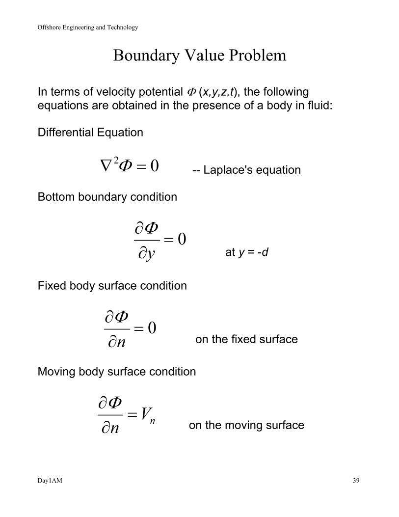
Boundary Value Problem
In terms of velocity potential Φ (x,y,z,t), the following equations are obtained in the presence of a body in fluid: Differential Equation
02 =∇ Φ -- Laplace's equation
Bottom boundary condition
0=∂∂
yΦ
at y = -d
Fixed body surface condition
0=∂∂
nΦ
on the fixed surface
Moving body surface condition
nVn
=∂∂Φ
on the moving surface

Offshore Engineering and Technology
Day1AM 40
Linear Wave Theory Development
The following assumption is made:
Waves are two-dimensional Problem is posed as determining:
either, the velocity potential or, the stream function
Perturbation technique
Express Φ as a power series in wave slope (i.e., wave height/ wave length)
Perturbation parameter LHkH πε ==
2
Then, the velocity potential is expressed as a series
nn
nΦεΦ ∑
∞
=
=1 −− Φn is the nth order potential
similarly, the free surface profile
nn
nηεη ∑
∞
=
=1 −− ηn is the nth order profile

Offshore Engineering and Technology
Day1AM 41
Linear Wave Theory (solution is obtained in a closed form) Dispersion relationship (relates the wave length or wave number to the wave frequency, wave period or wave speed)
kdkgc tanh2 =
or kdgk tanh2 =ω or kdTgL tanh2
2π=
Horizontal particle velocity
)](cos[coshcosh
2ctxk
kdksgkHu −=
ω
Vertical particle velocity
)](sin[coshsinh
2ctxk
kdksgkHv −=
ω
Horizontal particle acceleration
)](sin[coshcosh
2ctxk
kdksgkHu −=&
Vertical particle acceleration
)](cos[coshsinh
2ctxk
kdksgkHv −−=&
Dynamic pressure
)](cos[coshcosh
2ctxk
kdksHgp −= ρ

Offshore Engineering and Technology
Day1AM 42
Deepwater Criterion and Wave Length
Certain simplifications in the mathematical expressions describing properties of linear waves may be made if the water depth is very deep or very shallow. The following table describes these criteria:
Depth of Water Criterion )tanh(kd Deep water Deep water d/L = > 1/2 1 π2/2
0 gTL =
Shallow water d/L < = 1/20 kd gdTL =
Intermediate water depth
1/20 < d/L < 1/2 [ ] 2/100 )/2tanh( LdLL π=
For example, in deep water Horizontal particle velocity becomes
)](cos[)exp( ctxkkyTHu −=
π
Note the exponential decay term with respect to the vertical coordinate y. Similar expressions follow for the other quantities.

Offshore Engineering and Technology
Day1AM 43
Wave Particle Orbits and Velocity Amplitude Profiles
(c) SHALLOW WATER
201
Ld
<

Offshore Engineering and Technology
Day1AM 44
Sample Calculation of Linear Wave Properties
Water depth, d = 100 ft Wave Height, H = 20 ft Wave Period = 10 sec Elevation, y = 0 ft Deep water wave length
2 20 / 2 5.1248 512.48L gT T ftπ= = =
k0 = 0.01226
d/L0 = 0.1951
d/L = 0.2210
k = 0.01389
sinh kd = 1.88; cosh kd = 2.13
um = π.20/10 x 2.13/1.88 = 7.12 ft/sec
vm = π.20/10 = 6.28 ft/sec
mu& = 2π/10 x 7.12 = 4.47 ft2/sec
mv& = 2π/10 x 6.28 = 7.12 ft2/sec

Offshore Engineering and Technology
Day1AM 45
Time History of Linear Wave Properties
Note the phase relationships among variables
Offshore Engineering and Technology
Day1AM 46
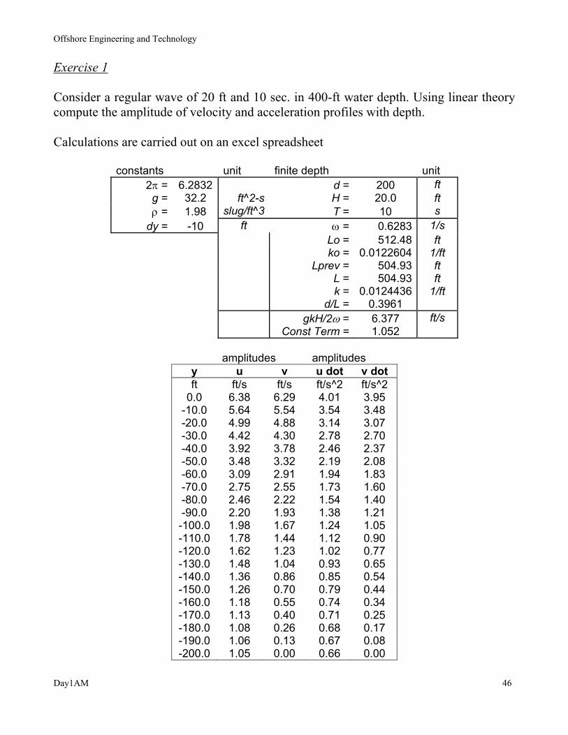
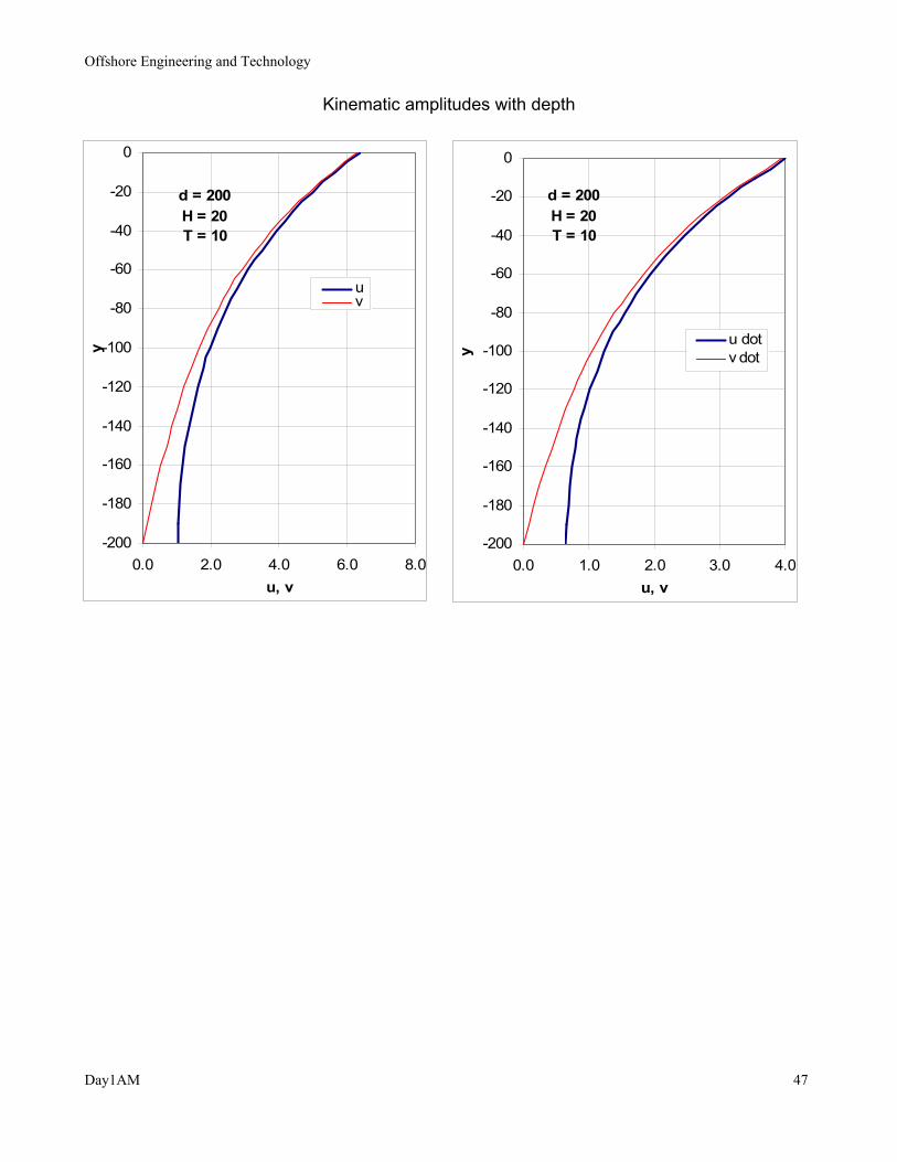
Exercise 1 Consider a regular wave of 20 ft and 10 sec. in 400-ft water depth. Using linear theory compute the amplitude of velocity and acceleration profiles with depth. Calculations are carried out on an excel spreadsheet
constants unit finite depth unit 2π = 6.2832 d = 200 ft g = 32.2 ft^2-s H = 20.0 ft ρ = 1.98 slug/ft^3 T = 10 s
dy = -10 ft ω = 0.6283 1/s Lo = 512.48 ft
ko = 0.0122604 1/ft Lprev = 504.93 ft L = 504.93 ft k = 0.0124436 1/ft d/L = 0.3961 gkH/2ω = 6.377 ft/s
Const Term = 1.052
amplitudes amplitudes y u v u dot v dot ft ft/s ft/s ft/s^2 ft/s^2
0.0 6.38 6.29 4.01 3.95 -10.0 5.64 5.54 3.54 3.48 -20.0 4.99 4.88 3.14 3.07 -30.0 4.42 4.30 2.78 2.70 -40.0 3.92 3.78 2.46 2.37 -50.0 3.48 3.32 2.19 2.08 -60.0 3.09 2.91 1.94 1.83 -70.0 2.75 2.55 1.73 1.60 -80.0 2.46 2.22 1.54 1.40 -90.0 2.20 1.93 1.38 1.21 -100.0 1.98 1.67 1.24 1.05 -110.0 1.78 1.44 1.12 0.90 -120.0 1.62 1.23 1.02 0.77 -130.0 1.48 1.04 0.93 0.65 -140.0 1.36 0.86 0.85 0.54 -150.0 1.26 0.70 0.79 0.44 -160.0 1.18 0.55 0.74 0.34 -170.0 1.13 0.40 0.71 0.25 -180.0 1.08 0.26 0.68 0.17 -190.0 1.06 0.13 0.67 0.08 -200.0 1.05 0.00 0.66 0.00
Offshore Engineering and Technology
Day1AM 47
Kinematic amplitudes with depth
d = 200H = 20T = 10
-200
-180
-160
-140
-120
-100
-80
-60
-40
-20
0
0.0 2.0 4.0 6.0 8.0u, v
y
uv
d = 200H = 20T = 10
-200
-180
-160
-140
-120
-100
-80
-60
-40
-20
0
0.0 1.0 2.0 3.0 4.0u, v
y
u dotv dot

Offshore Engineering and Technology
Day1AM 48
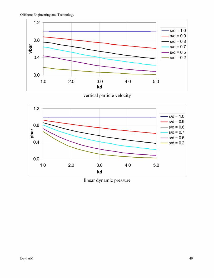
Non-dimensional horizontal particle velocity
kddskd
HTuu
sinh)/(cosh
)2/(20
0 ==π
Non-dimensional vertical particle velocity
kddskd
HTvv
sinh)/(sinh
)2/(20
0 ==π
Non-dimensional dynamic pressure
kddskd
Hgpp
cosh)/(cosh
)2/(0
0 ==ρ
0.0
0.5
1.0
1.5
1.0 2.0 3.0 4.0 5.0kd
ubar
s/d = 1.0s/d = 0.9s/d = 0.8s/d = 0.7s/d = 0.5s/d = 0.2
horizontal particle velocity
Offshore Engineering and Technology
Day1AM 49
0.0
0.4
0.8
1.2
1.0 2.0 3.0 4.0 5.0kd
vbar
s/d = 1.0s/d = 0.9s/d = 0.8s/d = 0.7s/d = 0.5s/d = 0.2
vertical particle velocity
0.0
0.4
0.8
1.2
1.0 2.0 3.0 4.0 5.0kd
pbar
s/d = 1.0s/d = 0.9s/d = 0.8s/d = 0.7s/d = 0.5s/d = 0.2
linear dynamic pressure

Offshore Engineering and Technology
Day1AM 50
Comparison of Linear Wave Pressures with Tank Measurements
Water depth = 10 ft Wave Periods = 1.25 – 3.0 sec
Offshore Engineering and Technology
Day1AM 51
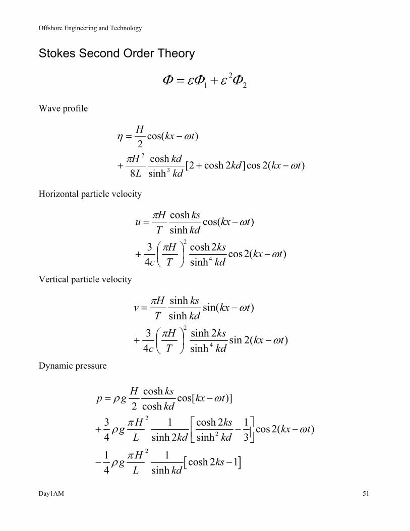
Stokes Second Order Theory
22
1 ΦεΦεΦ +=
Wave profile
)(2cos]2cosh2[sinhcosh
8
)cos(2
3
2
tkxkdkdkd
LH
tkxH
ωπ
ωη
−++
−=
Horizontal particle velocity
)(2cossinh
2cosh43
)cos(sinhcosh
4
2
tkxkdks
TH
c
tkxkdks
THu
ωπ
ωπ
−
+
−=
Vertical particle velocity
)(2sinsinh
2sinh43
)sin(sinhsinh
4
2
tkxkdks
TH
c
tkxkdks
THv
ωπ
ωπ
−
+
−=
Dynamic pressure
[ ]
2
2
2
cosh cos[ )]2 cosh
3 1 cosh 2 1 cos 2( )4 sinh 2 sinh 3
1 1 cosh 2 14 sinh
H ksp g kx tkd
H ksg kx tL kd kd
Hg ksL kd
ρ ω
πρ ω
πρ
= −
+ − −
− −

Offshore Engineering and Technology
Day1AM 52
First and second order components
Wave profile over one cycle
-1.25
0
1.25
0 90 180 270 360
Angle, deg.
Ampl
itude
1st2nd1st + 2nd
NOTE:
The higher order components yield the vertical asymmetry in the wave
profile.

Offshore Engineering and Technology
Day1AM 53
Example of First and Second Order
Horizontal Particle Velocity Components
Wave Height = 4 ft (1.22m)
Wave Period = 2 sec
Water Depth = 8 ft (2.44m)
The second order componet is less than 4 % of the first order velocity in this example.
Offshore Engineering and Technology
Day1AM 54
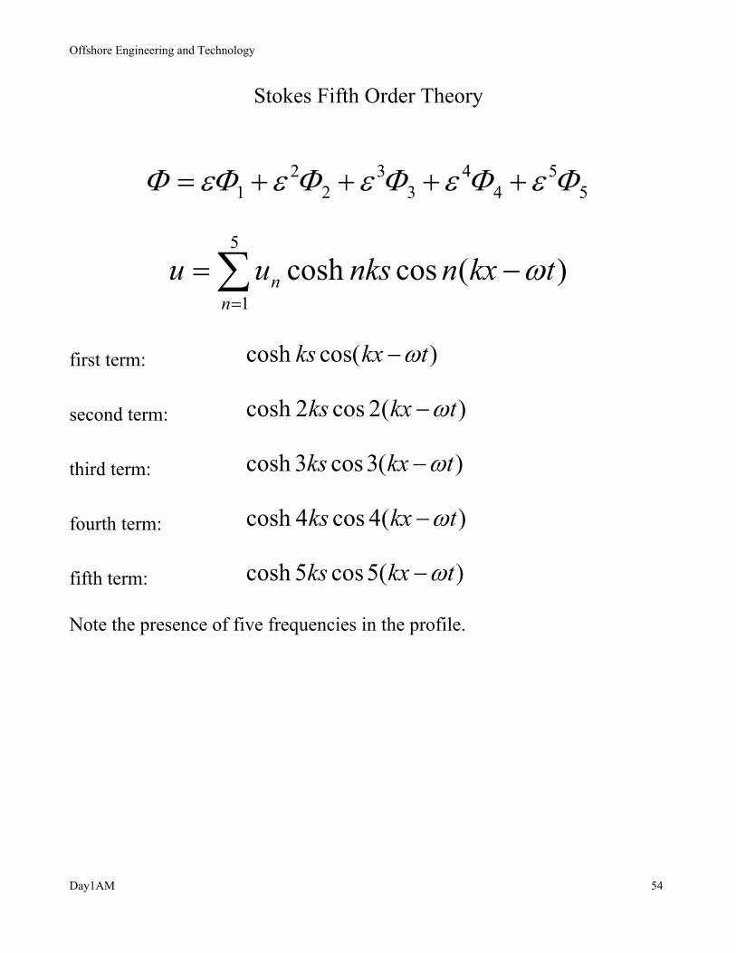
Stokes Fifth Order Theory
55
44
33
22
1 ΦεΦεΦεΦεΦεΦ ++++=
)(coscosh5
1tkxnnksuu
nn ω−= ∑
=
first term: )cos(cosh tkxks ω−
second term: )(2cos2cosh tkxks ω−
third term: )(3cos3cosh tkxks ω−
fourth term: )(4cos4cosh tkxks ω−
fifth term: )(5cos5cosh tkxks ω−
Note the presence of five frequencies in the profile.
Offshore Engineering and Technology
Day1AM 55
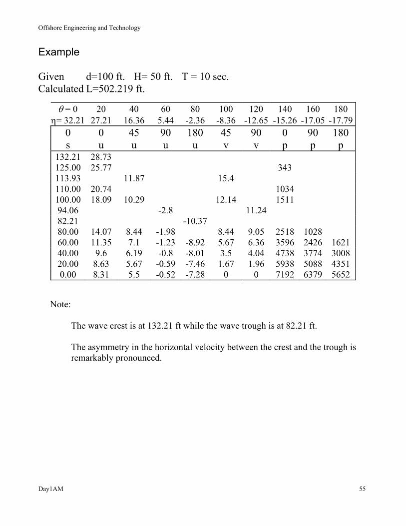
Example Given d=100 ft. H= 50 ft. T = 10 sec. Calculated L=502.219 ft.
θ = 0 20 40 60 80 100 120 140 160 180 η= 32.21 27.21 16.36 5.44 -2.36 -8.36 -12.65 -15.26 -17.05 -17.79
0 0 45 90 180 45 90 0 90 180 s u u u u v v p p p
132.21 28.73 125.00 25.77 343 113.93 11.87 15.4 110.00 20.74 1034 100.00 18.09 10.29 12.14 1511 94.06 -2.8 11.24 82.21 -10.37 80.00 14.07 8.44 -1.98 8.44 9.05 2518 1028 60.00 11.35 7.1 -1.23 -8.92 5.67 6.36 3596 2426 1621 40.00 9.6 6.19 -0.8 -8.01 3.5 4.04 4738 3774 3008 20.00 8.63 5.67 -0.59 -7.46 1.67 1.96 5938 5088 4351 0.00 8.31 5.5 -0.52 -7.28 0 0 7192 6379 5652
Note: The wave crest is at 132.21 ft while the wave trough is at 82.21 ft. The asymmetry in the horizontal velocity between the crest and the trough is remarkably pronounced.

Offshore Engineering and Technology
Day1AM 56
STREAM FUNCTION THEORY
Two Types:
(1) Symmetric Regular (theoretical)
(2) Irregular (when the measured profile is known)
Coordinate System
moves with wave speed, c in the direction of the wave propagation
Horizontal velocity = u - c
If current is present, add the current velocity, U to the above
Horizontal velocity = u – c + U
For irregular waves,
The measured wave profile is used as an additional constraint
Solution taken in a series form:
∑=
+=N
nnkxnksnXcyyx
1cossinh)(),(Ψ
where N is the order of Stream Function wave theory
The unknowns X(n) are solved by using the dynamic free surface boundary condition

Offshore Engineering and Technology
Day1AM 57
Order of Stream Function NORDER
Based on Wave Parameters d, H, T
This chart is useful in determining a suitable order of the stream
function theory in a particular wave case.
Offshore Engineering and Technology
Day1AM 58
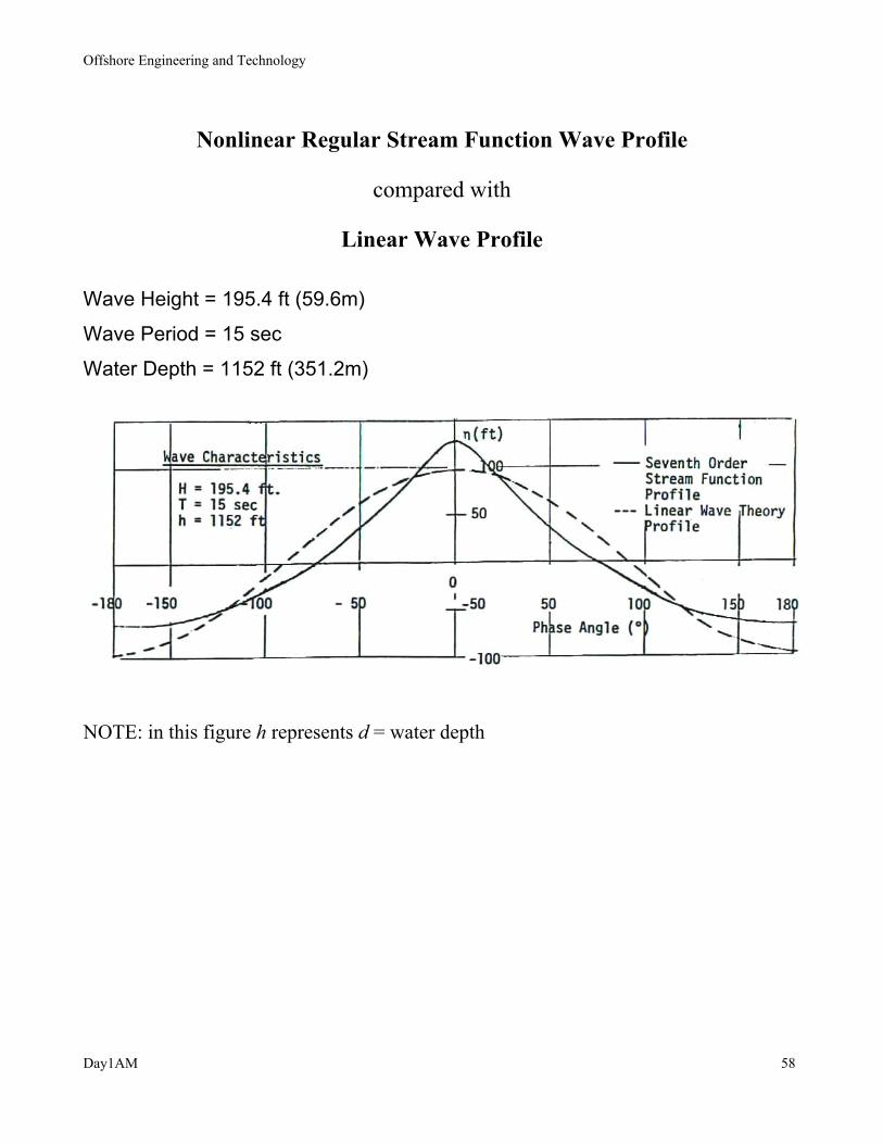
Nonlinear Regular Stream Function Wave Profile
compared with
Linear Wave Profile
Wave Height = 195.4 ft (59.6m)
Wave Period = 15 sec
Water Depth = 1152 ft (351.2m)
NOTE: in this figure h represents d = water depth

Offshore Engineering and Technology
Day1AM 59
Irregular Stream Function Wave vs. Experimental Pressure Amplitude
d = 10 ft; T > 3.00 sec

Offshore Engineering and Technology
Day1AM 60
Comparison of Computed Velocities with Measurements
Irregular Stream Function Theory
Water depth = 2.5 ft H/d = 0.7

Offshore Engineering and Technology
Day1AM 61
Region of application of wave theories

Offshore Engineering and Technology
Day1AM 62
PRACTICAL APPLICATION OF WAVE THEORIES
Wave Theories
Linear Theory
Low seastates (1 yr storm)
Swell
Large inertia dominated fixed and floating structures
Linear radiation damping
Fatigue analysis
Long term statistics
Stokes Second Order Theory
Slow drift oscillation of soft moored structures
TLP tendon analysis
Stokes Fifth Order or Stream Function Theory
Storm waves
Drag dominated structures
High wave tank data (irregular stream function)
Air gap or run-up
Deck waves