nonlinear control strategies for cascaded multilevel statcoms
TRANSCRIPT
IEEE TRANSACTIONS ON POWER DELIVERY, VOL. 19, NO. 4, OCTOBER 2004 1919
Nonlinear Control Strategies forCascaded Multilevel STATCOMs
Diego Soto, Member, IEEE, and Rubén Peña, Member, IEEE
Abstract—Two internal nonlinear control strategies based onthe feedback linearization technique for cascaded multilevel staticcompensators (STATCOMs) are presented. The strategies dependon the control capability of the converter output voltage and aresuitable for line frequency-switched converters. The first strategyconsiders a STATCOM where the voltage is set independently ofthe dc link voltage. Fast reactive power control within subcycletime response is achieved. The second strategy is constrained toa voltage whose amplitude remains proportional to the dc linkvoltage. Despite this limitation, the proposed strategy allows fullstabilization of the STATCOM dynamics and relatively fast controlof the reactive current (within one cycle). This may be adequatefor most STATCOM applications. Simulation results, using powersystem computer-aided design/electromagnetic transient program(PSCAD/EMTP), presented for both strategies confirm the ef-fectiveness of the control schemes to impose linear STATCOMdynamics. Preliminary experimental results from a five-levelprototype are presented for a converter using fixed control angles.
Index Terms—Flexible ac transmission systems (FACTS),multilevel converter, nonlinear control, static compensator(STATCOM), static var generator.
I. INTRODUCTION
THE static compensator (STATCOM) is the modern ver-sion of the well-established reactive power compensator.
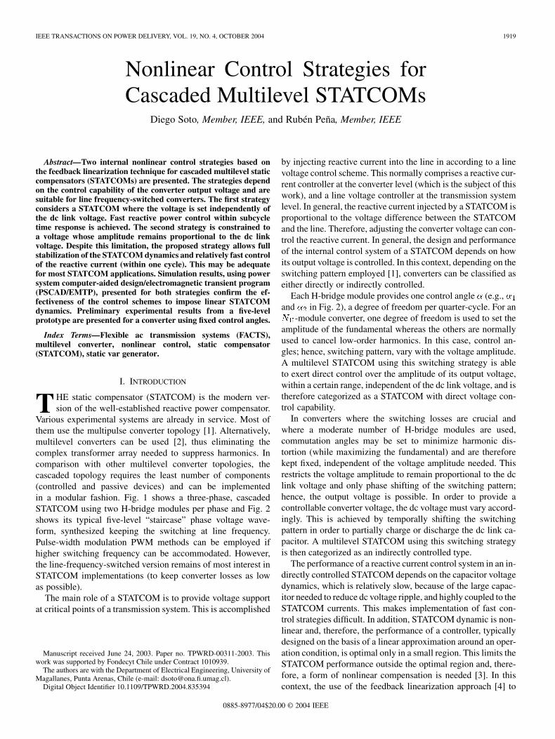
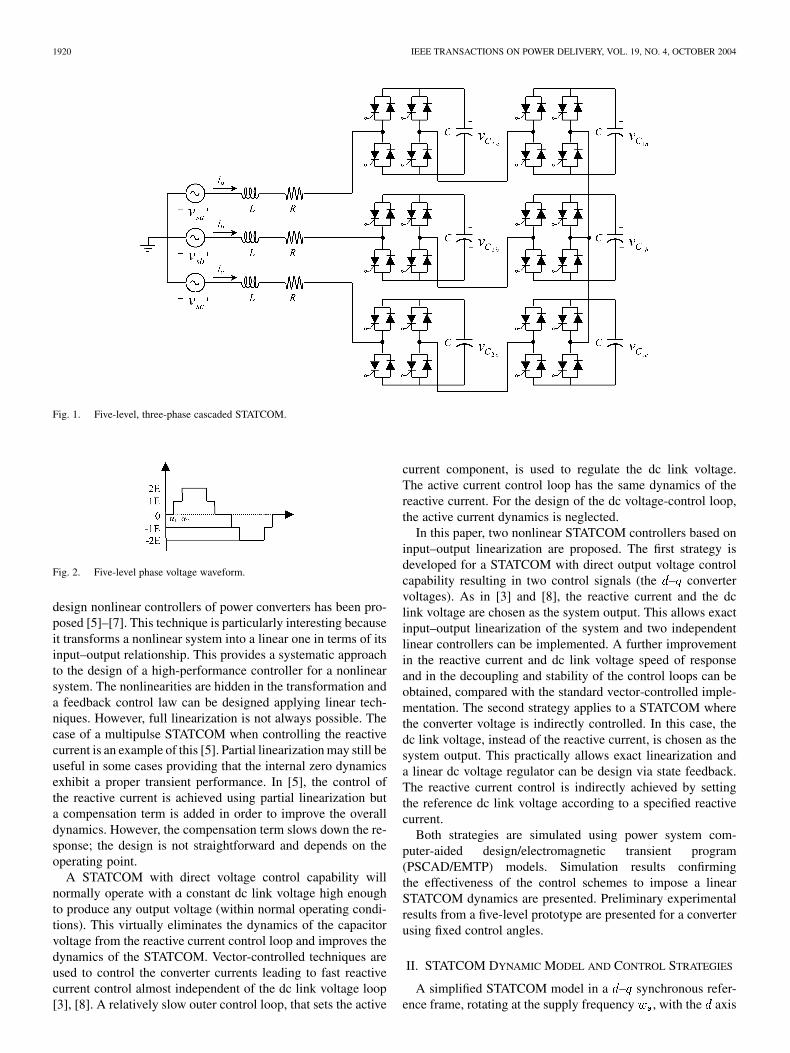
Various experimental systems are already in service. Most ofthem use the multipulse converter topology [1]. Alternatively,multilevel converters can be used [2], thus eliminating thecomplex transformer array needed to suppress harmonics. Incomparison with other multilevel converter topologies, thecascaded topology requires the least number of components(controlled and passive devices) and can be implementedin a modular fashion. Fig. 1 shows a three-phase, cascadedSTATCOM using two H-bridge modules per phase and Fig. 2shows its typical five-level “staircase” phase voltage wave-form, synthesized keeping the switching at line frequency.Pulse-width modulation PWM methods can be employed ifhigher switching frequency can be accommodated. However,the line-frequency-switched version remains of most interest inSTATCOM implementations (to keep converter losses as lowas possible).
The main role of a STATCOM is to provide voltage supportat critical points of a transmission system. This is accomplished
Manuscript received June 24, 2003. Paper no. TPWRD-00311-2003. Thiswork was supported by Fondecyt Chile under Contract 1010939.
The authors are with the Department of Electrical Engineering, University ofMagallanes, Punta Arenas, Chile (e-mail: [email protected]).
Digital Object Identifier 10.1109/TPWRD.2004.835394
by injecting reactive current into the line in according to a linevoltage control scheme. This normally comprises a reactive cur-rent controller at the converter level (which is the subject of thiswork), and a line voltage controller at the transmission systemlevel. In general, the reactive current injected by a STATCOM isproportional to the voltage difference between the STATCOMand the line. Therefore, adjusting the converter voltage can con-trol the reactive current. In general, the design and performanceof the internal control system of a STATCOM depends on howits output voltage is controlled. In this context, depending on theswitching pattern employed [1], converters can be classified aseither directly or indirectly controlled.
Each H-bridge module provides one control angle (e.g.,and in Fig. 2), a degree of freedom per quarter-cycle. For an
-module converter, one degree of freedom is used to set theamplitude of the fundamental whereas the others are normallyused to cancel low-order harmonics. In this case, control an-gles; hence, switching pattern, vary with the voltage amplitude.A multilevel STATCOM using this switching strategy is ableto exert direct control over the amplitude of its output voltage,within a certain range, independent of the dc link voltage, and istherefore categorized as a STATCOM with direct voltage con-trol capability.
In converters where the switching losses are crucial andwhere a moderate number of H-bridge modules are used,commutation angles may be set to minimize harmonic dis-tortion (while maximizing the fundamental) and are thereforekept fixed, independent of the voltage amplitude needed. Thisrestricts the voltage amplitude to remain proportional to the dclink voltage and only phase shifting of the switching pattern;hence, the output voltage is possible. In order to provide acontrollable converter voltage, the dc voltage must vary accord-ingly. This is achieved by temporally shifting the switchingpattern in order to partially charge or discharge the dc link ca-pacitor. A multilevel STATCOM using this switching strategyis then categorized as an indirectly controlled type.
The performance of a reactive current control system in an in-directly controlled STATCOM depends on the capacitor voltagedynamics, which is relatively slow, because of the large capac-itor needed to reduce dc voltage ripple, and highly coupled to theSTATCOM currents. This makes implementation of fast con-trol strategies difficult. In addition, STATCOM dynamic is non-linear and, therefore, the performance of a controller, typicallydesigned on the basis of a linear approximation around an oper-ation condition, is optimal only in a small region. This limits theSTATCOM performance outside the optimal region and, there-fore, a form of nonlinear compensation is needed [3]. In thiscontext, the use of the feedback linearization approach [4] to
0885-8977/04$20.00 © 2004 IEEE
1920 IEEE TRANSACTIONS ON POWER DELIVERY, VOL. 19, NO. 4, OCTOBER 2004
Fig. 1. Five-level, three-phase cascaded STATCOM.
Fig. 2. Five-level phase voltage waveform.
design nonlinear controllers of power converters has been pro-posed [5]–[7]. This technique is particularly interesting becauseit transforms a nonlinear system into a linear one in terms of itsinput–output relationship. This provides a systematic approachto the design of a high-performance controller for a nonlinearsystem. The nonlinearities are hidden in the transformation anda feedback control law can be designed applying linear tech-niques. However, full linearization is not always possible. Thecase of a multipulse STATCOM when controlling the reactivecurrent is an example of this [5]. Partial linearization may still beuseful in some cases providing that the internal zero dynamicsexhibit a proper transient performance. In [5], the control ofthe reactive current is achieved using partial linearization buta compensation term is added in order to improve the overalldynamics. However, the compensation term slows down the re-sponse; the design is not straightforward and depends on theoperating point.
A STATCOM with direct voltage control capability willnormally operate with a constant dc link voltage high enoughto produce any output voltage (within normal operating condi-tions). This virtually eliminates the dynamics of the capacitorvoltage from the reactive current control loop and improves thedynamics of the STATCOM. Vector-controlled techniques areused to control the converter currents leading to fast reactivecurrent control almost independent of the dc link voltage loop[3], [8]. A relatively slow outer control loop, that sets the active
current component, is used to regulate the dc link voltage.The active current control loop has the same dynamics of thereactive current. For the design of the dc voltage-control loop,the active current dynamics is neglected.
In this paper, two nonlinear STATCOM controllers based oninput–output linearization are proposed. The first strategy isdeveloped for a STATCOM with direct output voltage controlcapability resulting in two control signals (the – convertervoltages). As in [3] and [8], the reactive current and the dclink voltage are chosen as the system output. This allows exactinput–output linearization of the system and two independentlinear controllers can be implemented. A further improvementin the reactive current and dc link voltage speed of responseand in the decoupling and stability of the control loops can beobtained, compared with the standard vector-controlled imple-mentation. The second strategy applies to a STATCOM wherethe converter voltage is indirectly controlled. In this case, thedc link voltage, instead of the reactive current, is chosen as thesystem output. This practically allows exact linearization anda linear dc voltage regulator can be design via state feedback.The reactive current control is indirectly achieved by settingthe reference dc link voltage according to a specified reactivecurrent.
Both strategies are simulated using power system com-puter-aided design/electromagnetic transient program(PSCAD/EMTP) models. Simulation results confirmingthe effectiveness of the control schemes to impose a linearSTATCOM dynamics are presented. Preliminary experimentalresults from a five-level prototype are presented for a converterusing fixed control angles.
II. STATCOM DYNAMIC MODEL AND CONTROL STRATEGIES
A simplified STATCOM model in a – synchronous refer-ence frame, rotating at the supply frequency , with the axis
SOTO AND PEÑA: NONLINEAR CONTROL STRATEGIES FOR CASCADED MULTILEVEL STATCOMS 1921
aligned with the supply voltage vector is used. Regarding Fig. 1,is the equivalent interface inductance between the STATCOM
and the line and it accounts for the leakage inductance of thecoupling transformer and any added series inductance used forthis purpose, includes the corresponding resistance of this in-ductor and a resistance modeling the converter losses. The dy-namics of line currents and and the dc link voltage aregiven by
(1)
where is the total dc voltage defined as the summation ofthe voltage across the capacitors in one phase of the converter(capacitor voltages are assumed to be equal), is the supplyvoltage, and and are the – STATCOM voltages given by
(2)
In (2), is the STATCOM voltage vector position in the –frame and is the ratio between the peak amplitude of thephase converter voltage to the total dc voltage. This ratio de-pends on the control angles in the multilevel voltage wave-form and will be called modulation index hereafter. For the caseof Fig. 2, the modulation index can be calculated as
(3)
The model in (1) is similar to that developed in [3] for a multi-pulse STATCOM. The cascaded converter has multiple dc linksbut they can be represented as a single equivalent capacitor,
in (1), if dc link voltages are well balanced. This equiva-lent capacitor holds the total stored energy at the total dc linkvoltage . For the case of a three phase five-level converter
, where is the dc link capacitance of a singleconverter module (all six dc link capacitors are assumed to beequal).
A. STATCOM With Direct Voltage Control Capability
In this case, the voltage of the STATCOM can be controlledboth in magnitude and angle. Therefore, the converter - volt-ages can be controlled independently. For convenience, thesevoltages can be expressed in terms of a corresponding controlaction as
(4)
where and correspond to the modulation indexes in the– axis, respectively. Substituting (4) in (1) and neglecting the
inductance and converter losses and the change in the energy
stored in the inductance (i.e., considering asin [6] and [7]), then the dynamic of the STATCOM is given by
(5)
As in the standard vector-control approach [3], the aim of thecontrol strategy is to regulate the dc link voltage and control thereactive power current component; therefore, the output equa-tion is given by
(6)
The system described by (5) and (6) is a multiple-input–mul-tiple-output (MIMO) system with two inputs and two outputs.The system is coupled and nonlinear because it contains multi-plication of the states and input variables. In order to decoupleand linearize the model in (5), the input–output linearizationtechnique is applied [4].
It can be shown that the subsystem with the outputhas a relative degree equal two and the subsystem with output
has relative degree equal one. These subsystems can bedecoupled provided that the matrix in (7) is not singular
(7)
In this case, the decoupling matrix is
(8)
Considering normal operating conditions, (8) is not singular andthe system can be transformed into two decoupled linear sys-tems. The state variables in the linear and controllable systemare defined as
(9)
From (9), the following space-state equation is obtained:
(10)
1922 IEEE TRANSACTIONS ON POWER DELIVERY, VOL. 19, NO. 4, OCTOBER 2004
where and are the new control inputs. Equation (10) canbe used to design a control law for the tracking of a desiredtrajectory. However, in order to assure zero steady-state errorfor step reference changes and to overcome inaccuracies in themodel and parameter uncertainties, integral control is added to(10) as follows:
(11)
The two augmented linear systems are defined by
(12)
Therefore, the control laws are defined as
(13)
The feedback gains are obtained using pole placement proce-dure for given dynamics. The final control laws are given by
(14)
B. STATCOM With Indirect Voltage Control Capability
For a multilevel STATCOM restricted to use constant controlangles, the modulation index is constant. Therefore, the magni-tude of the output voltage is controlled indirectly by shifting theswitching pattern with respect to the line voltage. The outputvoltage in the - reference frame can be expressed as in (2) butwith constant modulation index
(15)
Considering , the system dynamics can be expressed as
(16)
A straightforward control strategy for reactive current controlbased on (16) requires as the system output, but then (16)will have a relative degree of one (because the first derivative of
depends on ). By inspection of , the control law wouldbe given by
(17)
A reactive current control loop with first-order dynamics and atime constant of a few milliseconds can be obtained using thisapproach. However, this yields to large and poorly damped os-cillations in the active current and dc voltage . This cor-responds to the two nonlinear zero dynamics, which are not af-fected by the control law. A small-signal analysis aroundshows that the natural frequency and damping coefficientof the oscillation are
(18)
To increase the damping of the oscillation, feedback ofis considered in [5]. This slows down the response but it haslittle effect on the performance of a STATCOM which is typi-cally used for line voltage support. The calculation of the feed-back gain is not trivial and system response may be optimal onlyin a small region since it depends on the operating conditions.In this work, to achieve full input–output linearization, istaken as the system output. Assuming is small, thenand ; therefore, (16) becomes
(19)
Using the linearization procedure described in [4], it is foundthat the nonlinear transformation in (20) transforms (19) into athird-order canonical linear system
(20)
As in the case described in Section II-A, integral compensationis also added to the dc link voltage. Therefore, the final controllaw is given by (21), shown at the bottom of the next page.
The feedback gains are obtained with standard pole place-ment procedure for a desired time response.
In order to control the reactive current, the dc voltage ref-erence is precalculated as the steady-state dc voltage neededto achieve the demanded reactive current. As the dc voltageevolves with the desired linear dynamics, so does the reactivecurrent, though with a small deviation (inverse transform isexact linear only for ).
SOTO AND PEÑA: NONLINEAR CONTROL STRATEGIES FOR CASCADED MULTILEVEL STATCOMS 1923
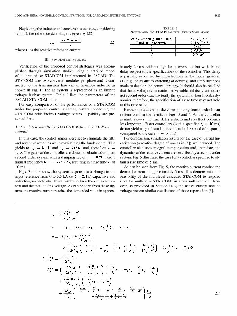
Neglecting the inductor and converter losses (i.e., considering), the reference dc voltage is given by (22)
(22)
where is the reactive reference current.
III. SIMULATION STUDIES
Verification of the proposed control strategies was accom-plished through simulation studies using a detailed modelof a three-phase STATCOM implemented in PSCAD. TheSTATCOM uses two converter modules per phase and is con-nected to the transmission line via an interface inductor asshown in Fig. 1. The ac system is represented as an infinitevoltage busbar system. Table I lists the parameters of thePSCAD STATCOM model.
For easy comparison of the performance of a STATCOMunder the proposed control schemes, results concerning theSTATCOM with indirect voltage control capability are pre-sented first.
A. Simulation Results for STATCOM With Indirect VoltageControl
In this case, the control angles were set to eliminate the fifthand seventh harmonics while maximizing the fundamental. Thisyields to and and, therefore,
. The gains of the controller are chosen to obtain a dominantsecond-order system with a damping factor and anatural frequency , resulting in a rise time of10 ms.
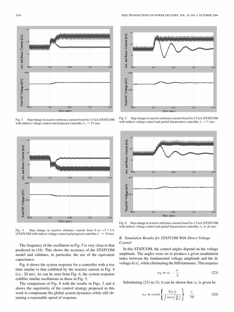
Figs. 3 and 4 show the system response to a change in theinput reference from 0 to 3.5 kA (at s) capacitive andinductive, respectively. These results include the - axes cur-rent and the total dc link voltage. As can be seen from these fig-ures, the reactive current reaches the demanded value in approx-
TABLE ISYSTEM AND STATCOM PARAMETER USED IN SIMULATIONS
imately 20 ms, without significant overshoot but with 10-msdelay respect to the specifications of the controller. This delayis partially explained by imperfections in the model given in(1) [e.g., delay due to switching of devices], and simplificationsmade to develop the control strategy. It should also be recalledthat the dc voltage is the controlled variable and its dynamics arenot second order exact, actually the system has fourth-order dy-namics; therefore, the specification of a rise time may not holdat this time scale.
Further simulations of the corresponding fourth-order linearsystem confirm the results in Figs. 3 and 4. As the controlleris made slower, the time delay reduces and its effect becomesless important. Faster controllers (with a specified ms)do not yield a significant improvement in the speed of response(compared to the case ms).
For comparison, simulation results for the case of partial lin-earization (a relative degree of one as in [5]) are included. Thecontroller also uses integral compensation and, therefore, thedynamics of the reactive current are described by a second-ordersystem. Fig. 5 illustrates the case for a controller specified to ob-tain a rise time of 5 ms.
As can be seen from Fig. 5, the reactive current reaches thedemand current in approximately 5 ms. This demonstrates thefeasibility of the multilevel cascaded STATCOM to respond(like the multipulse STATCOM) in a few milliseconds. How-ever, as predicted in Section II-B, the active current and dcvoltage present similar oscillations of those reported in [5].
(21)
1924 IEEE TRANSACTIONS ON POWER DELIVERY, VOL. 19, NO. 4, OCTOBER 2004
Fig. 3. Step change in reactive reference current from 0 to 3.5 kA (STATCOMwith indirect voltage control and proposed controller, t = 10 ms).
Fig. 4. Step change in reactive reference current from 0 to �3:5 kA
(STATCOM with indirect voltage control and proposed controller, t = 10ms).
The frequency of the oscillation in Fig. 5 is very close to thatpredicted in (18). This shows the accuracy of the STATCOMmodel and validates, in particular, the use of the equivalentcapacitance.
Fig. 6 shows the system response for a controller with a risetime similar to that exhibited by the reactive current in Fig. 4(i.e., 20 ms). As can be seen from Fig. 6, the system responseexhibits similar oscillations as those in Fig. 5.
The comparison of Fig. 6 with the results in Figs. 3 and 4shows the superiority of the control strategy proposed in thiswork to compensate the global system dynamics while still ob-taining a reasonable speed of response.
Fig. 5. Step change in reactive reference current from 0 to 3.5 kA (STATCOMwith indirect voltage control and partial linearization controller, t = 5 ms).
Fig. 6. Step change in reactive reference current from 0 to 3.5 kA (STATCOMwith indirect voltage control and partial linearization controller, t = 20 ms).
B. Simulation Results for STATCOM With Direct VoltageControl
In this STATCOM, the control angles depend on the voltageamplitude. The angles were set to produce a given modulationindex between the fundamental voltage amplitude and the dcvoltage , while eliminating the fifth harmonic. This requires
(23)
Substituting (23) in (3), it can be shown that is given by
(24)
SOTO AND PEÑA: NONLINEAR CONTROL STRATEGIES FOR CASCADED MULTILEVEL STATCOMS 1925
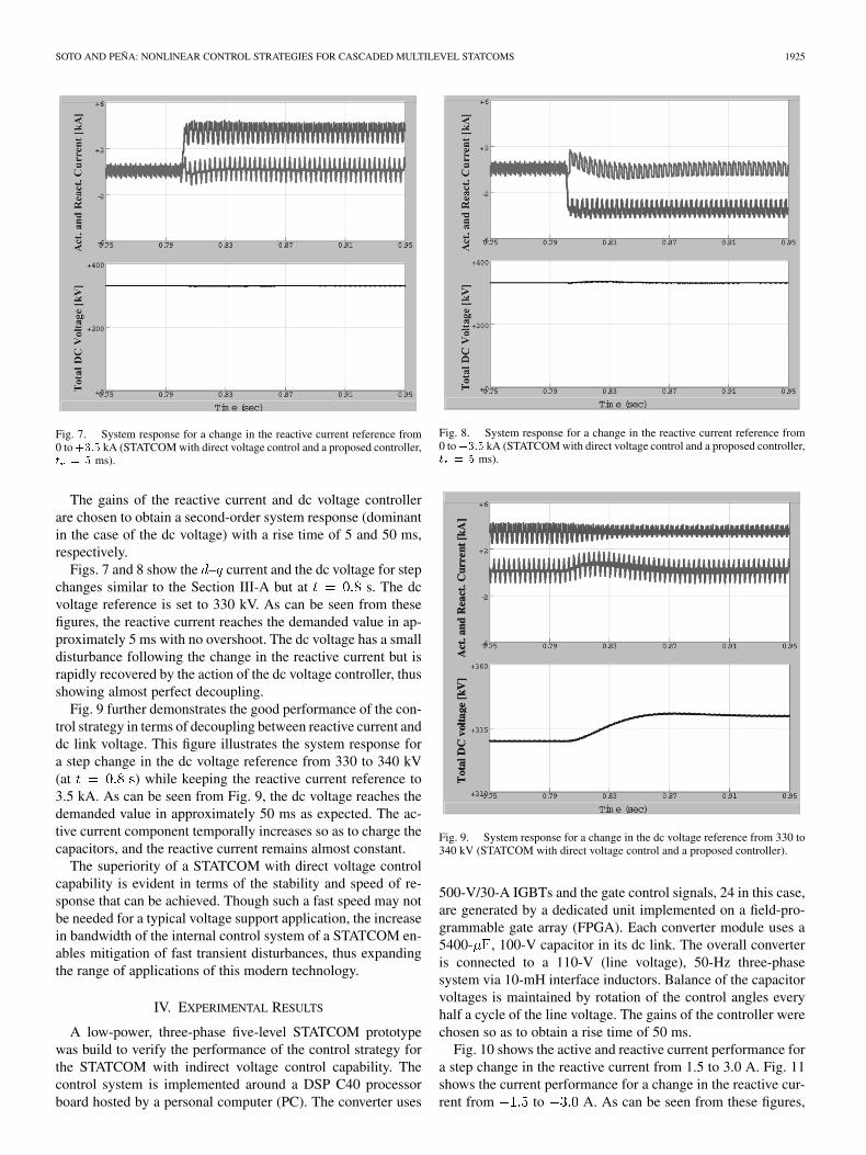
Fig. 7. System response for a change in the reactive current reference from0 to+3:5 kA (STATCOM with direct voltage control and a proposed controller,t = 5 ms).
The gains of the reactive current and dc voltage controllerare chosen to obtain a second-order system response (dominantin the case of the dc voltage) with a rise time of 5 and 50 ms,respectively.
Figs. 7 and 8 show the – current and the dc voltage for stepchanges similar to the Section III-A but at s. The dcvoltage reference is set to 330 kV. As can be seen from thesefigures, the reactive current reaches the demanded value in ap-proximately 5 ms with no overshoot. The dc voltage has a smalldisturbance following the change in the reactive current but israpidly recovered by the action of the dc voltage controller, thusshowing almost perfect decoupling.
Fig. 9 further demonstrates the good performance of the con-trol strategy in terms of decoupling between reactive current anddc link voltage. This figure illustrates the system response fora step change in the dc voltage reference from 330 to 340 kV(at ) while keeping the reactive current reference to3.5 kA. As can be seen from Fig. 9, the dc voltage reaches thedemanded value in approximately 50 ms as expected. The ac-tive current component temporally increases so as to charge thecapacitors, and the reactive current remains almost constant.
The superiority of a STATCOM with direct voltage controlcapability is evident in terms of the stability and speed of re-sponse that can be achieved. Though such a fast speed may notbe needed for a typical voltage support application, the increasein bandwidth of the internal control system of a STATCOM en-ables mitigation of fast transient disturbances, thus expandingthe range of applications of this modern technology.
IV. EXPERIMENTAL RESULTS
A low-power, three-phase five-level STATCOM prototypewas build to verify the performance of the control strategy forthe STATCOM with indirect voltage control capability. Thecontrol system is implemented around a DSP C40 processorboard hosted by a personal computer (PC). The converter uses
Fig. 8. System response for a change in the reactive current reference from0 to�3:5 kA (STATCOM with direct voltage control and a proposed controller,t = 5 ms).
Fig. 9. System response for a change in the dc voltage reference from 330 to340 kV (STATCOM with direct voltage control and a proposed controller).
500-V/30-A IGBTs and the gate control signals, 24 in this case,are generated by a dedicated unit implemented on a field-pro-grammable gate array (FPGA). Each converter module uses a5400- , 100-V capacitor in its dc link. The overall converteris connected to a 110-V (line voltage), 50-Hz three-phasesystem via 10-mH interface inductors. Balance of the capacitorvoltages is maintained by rotation of the control angles everyhalf a cycle of the line voltage. The gains of the controller werechosen so as to obtain a rise time of 50 ms.
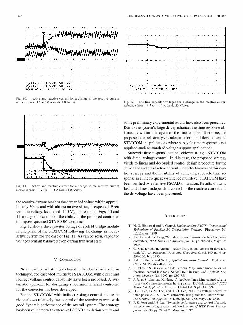
Fig. 10 shows the active and reactive current performance fora step change in the reactive current from 1.5 to 3.0 A. Fig. 11shows the current performance for a change in the reactive cur-rent from to A. As can be seen from these figures,
1926 IEEE TRANSACTIONS ON POWER DELIVERY, VOL. 19, NO. 4, OCTOBER 2004
Fig. 10. Active and reactive current for a change in the reactive currentreference from 1.5 to 3.0 A (scale 1.0 A/div).
Fig. 11. Active and reactive current for a change in the reactive currentreference from �1:5 to �3:0 A (scale 1.0 A/div).
the reactive current reaches the demanded values within approx-imately 50 ms and with almost no overshoot, as expected. Evenwith the voltage level used (110 V), the results in Figs. 10 and11 are a good example of the ability of the proposed controllerto impose specified STATCOM dynamics.
Fig. 12 shows the capacitor voltage of each H-bridge modulein one phase of the STATCOM following the change in the re-active current for the case of Fig. 11. As can be seen, capacitorvoltages remain balanced even during transient state.
V. CONCLUSION
Nonlinear control strategies based on feedback linearizationtechnique, for cascaded multilevel STATCOM with direct andindirect voltage control capability have been proposed. A sys-tematic approach for designing a nonlinear internal controllerfor the converter has been developed.
For the STATCOM with indirect voltage control, the tech-nique allows relatively fast control of the reactive current withgood dynamic performance of the overall system. The strategyhas been validated with extensive PSCAD simulation results and
Fig. 12. DC link capacitor voltages for a change in the reactive currentreference from �1:5 to �3:0 A (scale 20 V/div).
some preliminary experimental results have also been presented.Due to the system’s large dc capacitance, the time response ob-tained is within one cycle of the line voltage. Therefore, theproposed control strategy is adequate for a multilevel cascadedSTATCOM in applications where subcycle time response is notrequired such as standard voltage support applications.
Subcycle time response can be achieved using a STATCOMwith direct voltage control. In this case, the proposed strategyyields to linear and decoupled control design procedure for thedc voltage and the reactive current. The effectiveness of this con-trol strategy and the feasibility of achieving subcycle time re-sponse in a line frequency-switched multilevel STATCOM havebeen verified by extensive PSCAD simulation. Results showingfast and almost independent control of the reactive current andthe dc voltage have been presented.
REFERENCES
[1] N. G. Hingorani and L. Gyugyi, Understanding FACTS: Concepts andTechnology of Flexible AC Transmission Systems. Piscataway, NJ:IEEE Press, 1999.
[2] J.-S. Lai and F. Z. Peng, “Multilevel converters—A new breed of powerconverters,” IEEE Trans. Ind. Applicat., vol. 32, pp. 509–517, May/June1996.
[3] C. Shauder and H. Mehta, “Vector analysis and control of advancedstatic VAr compensators,” Proc. Inst. Elect. Eng. C, vol. 140, no. 4, pp.299–306, July 1993.
[4] J.-J. E. Slotine and W. Li, Applied Nonlinear Control. EnglewoodCliffs, NJ: Prentice-Hall, 1991.
[5] P. Peticlair, S. Bahoha, and J.-P. Ferrieux, “Optimized linearization viafeedback control law for a STATCOM,” in Proc. Ind. Applicat. Soc.Annu. Meeting, Oct. 1997, pp. 880–885.
[6] J. Jung, S. Lim, and K. Nam, “A feedback linearizing control schemefor a PWM converter-inverter having a small DC-link capacitor,” IEEETrans. Ind. Applicat., vol. 35, pp. 1124–1131, Sept./Oct. 1999.
[7] D.-C. Lee, G.-M. Lee, and K.-D. Lee, “DC-Bus voltage control ofthree-phase AC/DC PWM converters using feedback linearization,”IEEE Trans. Ind. Applicat., vol. 36, pp. 826–833, May/June 2000.
[8] F. Z. Peng and J.-S. Lai, “Dynamic performance and control of a staticvar generator using cascade multilevel inverters,” IEEE Trans. Ind. Ap-plicat., vol. 33, pp. 748–755, May/June 1997.

SOTO AND PEÑA: NONLINEAR CONTROL STRATEGIES FOR CASCADED MULTILEVEL STATCOMS 1927
Diego Soto (S’96–M’98) received the Eng. degree inelectrical engineering from the University of Maga-llanes, Punta Arenas, Chile, in 1990, and the Ph.D.degree from Imperial College, University of London,London, U.K., in 1999.
Currently, he is a Lecturer in Power Electronicswith the Department of Electrical Engineering, Uni-versity of Magallanes, where he has been since 1991.His research interests include high-power power con-verters for flexible ac transmission system (FACTS)controllers and the control of static converters.
Rubén Peña (S’95–M’97) was born in Coronel,Chile. He received the Electrical Engineering degreefrom the University of Concepcion, Concepcion,Chile, in 1984 and the M.Sc. and Ph.D. degrees fromthe University of Nottingham, Nottingham, U.K., in1992 and 1996, respectively.
Currently, he is with the Electrical EngineeringDepartment, University of Magallanes, PuntaArenas, Chile. From 1985 to 1991, he was a Lecturerin the University of Magallanes. His research inter-ests include control of power electronics converters,
ac drives, and renewable energy systems.