nitrogen + syn gas jan 2013 (ammonia)
TRANSCRIPT
AmmoniA operAtions
Nitrogen+Syngas 321 | January - February 2013 � 1
The ammonia industry has seen sig-nificant change in recent decades as high turnover, leaner organisational
structures, and new operations have shifted the demographics of the operations and technical personnel staff. These changes have resulted in a loss of long-term opera-tional knowledge and can lead to incidents of equipment and catalyst damage during operation and upset conditions.
As catalyst technology continues to improve, the products’ high performance are best enabled when accompanied by a thorough understanding of the chemical and physical principles of catalytic reactions1.
Carbon formation in primary reformers
An important step in the ammonia manu-facturing process is steam reforming; the conversion of hydrocarbons into hydrogen. The primary reformer is the main piece of equipment for this and represents the larg-est expenditure in terms of capital and on-going energy costs. Optimum performance of the reformer and the installed reforming catalyst is critical to ensuring high plant productivity and efficiency. Poisoning, foul-ing or incorrect operation can adversely
affect the catalyst’s performance and can lead to costly equipment failure.
Primary reformer reactionsThe main reactions in the primary reformer are:
Steam reforming of hydrocarbons
CnH2n+2 + n H2O n CO + (2n+1) H2 ∆H > 0Steam reforming of methane
CH4 + H2O CO + 3 H2
∆H = 88700 Btu/lb-mole (206 kJ/mol)Water-gas shift
CO + H2O CO2 + H2
∆H = -17,600 Btu/lb-mole (-41 kJ/mol)
Overall, the process is endothermic. A lower CH4 leakage is favoured by higher exit tem-perature, higher steam-to-carbon ratio, and lower exit pressure.
The standard primary reformer system is comprised of a tubular furnace where the feed stream passes over a catalyst packed in multiple banks of externally heated tubes. With improvements in tube metallurgy, primary reformers operate at pressures up to 6,000 kPa and tube wall
temperatures up to 1010°C. The aver-age heat flux may be as high as 94,000-110,000 W/m2.
Firing is usually controlled such that tube wall temperatures are maintained at values that will give a reasonable tube life. By design and industry practice, maximum allowable tube wall temperatures give an in-service life of about 100,000 hours.
Carbon formation reactionsWith no steam present and at normal reformer operating temperatures, all hydro-carbons will decompose into carbon and hydrogen via the following reaction:Thermal cracking
CH4 C + 2 H2
Cracking reactions are favoured thermody-namically at high temperature. In the pres-ence of steam, gasification reactions also occur over the primary reformer catalyst as:Gasification
C + H2O CO + H2
Operating the reformer at conditions that drive this reaction can prevent the accumu-lation of carbon deposits. When conditions exist that favour hydrocarbon cracking, the heavier hydrocarbons in the feed will
Key�lessons�to�optimise�ammonia�plant�performanceUnderstanding the basic principles of catalytic reactor operation in an ammonia plant can
help to avoid costly performance and operating problems. M. Anderson, and S. Osborne
of Clariant Corporation (formerly Süd-Chemie) focus on three particular topics that have
a significant impact on production performance: 1) chemistry, consequences and avoidance
of carbon formation in the steam reformer; 2) proper flow distribution in catalytic reactors,
and 3) the impact of improper plant operation on catalyst and equipment.

AmmoniA operAtions
2� Nitrogen+Syngas 321 | January - February 2013
1500
1550
1600
1650
1700
1750
0 5 10 15
tem
pera
ture
, °F
months on stream
BenchmarkClariant
Fig 1: Comparative average TWT surveys of two charges of catalyst at a 1200 STPD ammonia plant
Fig 2: IR thermographic image of a row of reformer tubes
1500152515501575160016251650
EWEE
DWDE
CWCE
BWBE
AWAE
1625-1650
temperature °F
1600-16251575-16001550-15751525-15501500-1525
North
1625-1650
temperature °F
1600-16251575-16001550-15751525-15501500-1525
top level: surface profiletop level: surface profile
top level: top profiletop level: top profile
North
EWEE
DWDE
CWCE
BWBE
AWAE
Fig 3: Plotted TWT surveys showing the heat distribution across the reformer
crack first. As this occurs, the active sites of the catalyst become masked, resulting in less reforming reaction and higher gas temperatures, which further increases the tendency for cracking and coke deposition.
Common causes of carbon formation and deposition are low steam/gas ratio operation, heavy hydrocarbons in the feed, sulphur poisoning, and temperature excur-sions resulting from poor firing control. Higher catalyst activity can reduce carbon formation potential by lowering gas temper-ature when methane concentration is high enough for cracking, thereby reducing the carbon formation potential.
The overall effect of carbon formation on the primary reformer is reduced conversion, increased pressure drop and increased tube wall temperatures which, if severe, can be seen as ‘hot bands’ on the tubes. Not only does the carbon deposit block active sites, its formation within the pores of the catalyst can cause catalyst breakage.
Monitoring programDuring routine operation of a primary reformer, a monitoring program assists in optimising the catalyst’s performance as well as providing early detection of issues that can lead to catalyst or tube failure. Three performance parameters are typically trended during operation; calculated CH4 approach to equilibrium (ATE), tube wall tem-peratures (TWT), and relative pressure drop.
Approach to equilibriumReformer catalyst activity is commonly expressed as CH4 ATE, which is the differ-ence between the measured catalyst outlet temperature and the calculated equilibrium temperature for the observed methane leakage. An increased ATE or methane slip from the front-end results in a higher purge rate from the synthesis loop and increased energy consumption for the plant. While operating the primary reformer at higher exit temperature can mitigate this effect, the cost of increased fuel requirements and the impact of hotter tube wall tempera-tures must be considered when choosing to operate in that non-optimal mode.
Tube wall temperaturesTube costs are a significant item in the overall economics of a reforming plant. The goal is to operate the reformer under conditions that result in the lowest possi-ble tube wall temperatures (TWTs) consist-ent with satisfactory reformed gas quality. Even a slight increase in the tube wall
temperatures will have a drastic impact on the tube life. A TWT increase of as little as 10oC may result in up to a 30% shortened life-time of the reformer tubes.
The use of a high activity/shape opti-mised reforming catalyst results in lower tube wall temperatures and a significant cost and efficiency advantage to an opera-tor. As an example, a 1,200 short t/d plant in North America was able to realise such an advantage by installing the high activity ReforMax
® reforming catalyst from Clariant.
The Kellogg-designed primary reformer of this plant was initially designed to produce 600 short t/d of ammonia. After several expansions, the reformer now operates at a high heat flux of around 110,000 W/m2. Figure 1 shows that the mean TWT is 55°C cooler with catalyst from Clariant than with the previous competitor charge.
Additionally, the maximum tube wall temperature was also lowered and the number of tubes with TWTs exceeding the temperature limit of 927°C was cut from five to zero, significantly reducing the risk of potential tube failure.
Effective monitoring of the TWTs and balancing of the firing of the reformer fur-nace can extend the life of the tubes and optimise the performance of the catalyst (Figures 2 and 3).
Pressure dropThe impact of increasing primary reformer pressure drop is reduced plant efficiency, caused by the lowering of the suction pres-sure at the synthesis gas compressor, and the resulting higher horsepower require-ments to maintain the desired loop pres-sure. Depending on pressure relief valve set-points, a higher reformer ∆P may also require reduction of plant operating rates if near those limits.
Using Clariant’s proprietary Cat-Trends®
program, calculated ATE and relative pressure drop can be trended over time. Carbon deposition on the catalyst will manifest itself as increasing ATE, increas-ing relative pressure drop and increasing TWTs. In severe cases, visual hot bands on the tubes will also become evident.
Operational control factors for minimising carbon formationTo prevent carbon formation, a minimum steam-to-carbon (S/C) ratio must be main-tained at all times. This value is contingent on the composition of the feed gas, firing rates, operating pressure and incoming feed temperature. Most carbon formation

AmmoniA operAtions
Nitrogen+Syngas 321 | January - February 2013 � 3
0
10
20
30
40
50
60
70
0.0 1.0 2.0 3.0sulphur in feed, ppmv
incr
ease
in tu
bewa
ll te
mp,
°F
Fig 4: The impact of sulphur concentration in feed gas on the tube wall temperature in the reformer
Fig 5: The reformer tube appearance before and after a decoking procedure
incidents occur, however, during transient conditions such as start-up, operating trips or shutdowns. Modern operating plants typically have a low S/C trip interlock that cuts out the feed-gas to protect the reformer during upset conditions. Addition-ally, a properly installed minimum stop on the steam valve ensures that steam con-tinues to flow through the reformer in an emergency trip to sweep all feed-gas out of the reformer. Complete isolation of the feed-gas valve during a trip or shut-down is necessary before steam cut-out.
Controlled start-up and shutdown pro-cedures and emergency interlocks are designed to avoid carbon formation. The objectives are to:l Prevent over-firing and thus tempera-
ture excursions during rate changes. This typically considers the following operating parameters: fuel flow, fuel pressure, flue-gas temperature, proc-ess gas pressure, steam flow, feed-gas flow, combustion air flow, exit process gas temperature and the number and location of burners lit. Often a manual start-up rate guide is used and in some cases an algorithm with interlocks guides the operator during the start-up.
l Maintain a high S/C ratio during rate changes. This is typically achieved by increasing the steam flow before the feed-gas on start-up and reducing the feed-gas before the steam on shutdowns.
l Ensure sufficient and even flow distri-bution throughout the entire reformer. Before feed gas is introduced to the reformer during start-up, the steam flow should be sufficient to ensure
that all tubes have similar operating conditions i.e. even flow and even heat through all tubes.
l Ensure sufficient steam flow exists for adequate mixing of steam and feed-gas well before the tube inlet manifold.
Visual monitoring of the tubes and burners is critical to detect any issues during the start-up process.
Sulphur poisoning as root cause for carbon formationSulphur has an adverse impact on reform-ing catalyst activity as it reacts with the reforming catalysts active nickel compo-nent and forms an equilibrium condition over the active sites of the catalyst:
Ni + H2S NiS + H2
The sulphur must be removed from the
feed-gas in an upstream desulphurisation step to levels less than 0.1 ppmv. Sulphur is not a permanent poison for short-term exposures and when removed from the feed, the catalyst can regain the original activity. However, sulphur poisoning can deactivate the catalyst to the extent that less reforming is done and elevated gas temperatures cause high tube wall tem-peratures. Even small amounts of sulphur in the feed can significantly influence the tube wall temperatures as shown in Fig. 4.
If the temperature rises to the point where carbon formation occurs, pressure drop will increase and catalyst perform-ance will be further compromised.
In a 600 short t/d design ammonia plant, the desulphurisation unit was bypassed due to vessel design concerns. During this time, the high performance ReforMax primary reformer catalyst was exposed to inlet sul-phur levels of up to 3 ppmv for nine months. As expected, catalyst poisoning occurred which resulted in activity loss in the 30-40% top inlet tube location.
The plant was subsequently brought down and a successful steam-air regenera-tion procedure was done with the assistance of Clariant technical support. On re-start, the reformer experienced full recovery to pre-inci-dent performance levels and tube wall tem-peratures; visual success of the decoking procedure is reflected in Fig. 5.
The ReforMax catalyst withstood the intense conditions during this high sulphur exposure time-frame and continued to pro-vide the full expected design life-time.
Given the impact of sulphur poisoning on the performance of the reformer, the
AmmoniA operAtions
4� Nitrogen+Syngas 321 | January - February 2013
0
0.1
0.2
0.3
0.4
0.5
0.6
0.7
1 10 14 17 19 25 34time on-stream, months
CH4 l
eaka
ge, %
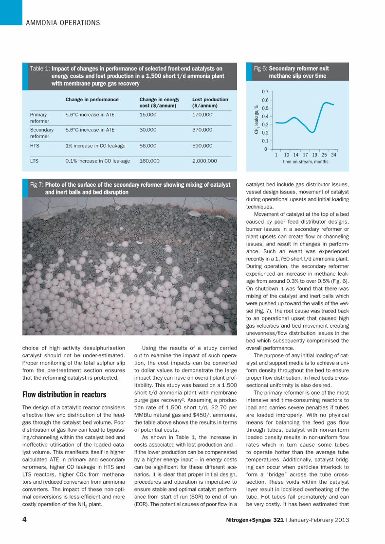
Fig 6: Secondary reformer exit methane slip over time
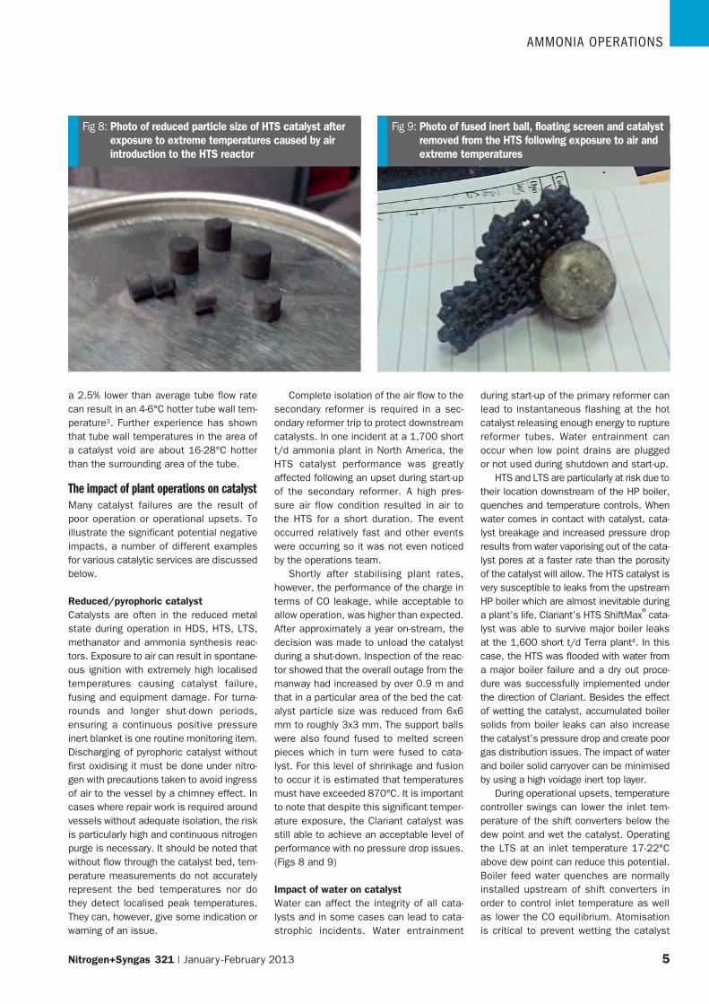
Fig 7: Photo of the surface of the secondary reformer showing mixing of catalyst and inert balls and bed disruption
choice of high activity desulphurisation catalyst should not be under-estimated. Proper monitoring of the total sulphur slip from the pre-treatment section ensures that the reforming catalyst is protected.
Flow distribution in reactorsThe design of a catalytic reactor considers effective flow and distribution of the feed-gas through the catalyst bed volume. Poor distribution of gas flow can lead to bypass-ing/channeling within the catalyst bed and ineffective utilisation of the loaded cata-lyst volume. This manifests itself in higher calculated ATE in primary and secondary reformers, higher CO leakage in HTS and LTS reactors, higher COx from methana-tors and reduced conversion from ammonia converters. The impact of these non-opti-mal conversions is less efficient and more costly operation of the NH3 plant.
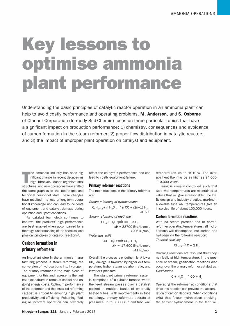
Using the results of a study carried out to examine the impact of such opera-tion, the cost impacts can be converted to dollar values to demonstrate the large impact they can have on overall plant prof-itability. This study was based on a 1,500 short t/d ammonia plant with membrane purge gas recovery2. Assuming a produc-tion rate of 1,500 short t/d, $2.70 per MMBtu natural gas and $450/t ammonia, the table above shows the results in terms of potential costs.
As shown in Table 1, the increase in costs associated with lost production and – if the lower production can be compensated by a higher energy input – in energy costs can be significant for these different sce-narios. It is clear that proper initial design, procedures and operation is imperative to ensure stable and optimal catalyst perform-ance from start of run (SOR) to end of run (EOR). The potential causes of poor flow in a
catalyst bed include gas distributor issues, vessel design issues, movement of catalyst during operational upsets and initial loading techniques.
Movement of catalyst at the top of a bed caused by poor feed distributor designs, burner issues in a secondary reformer or plant upsets can create flow or channeling issues, and result in changes in perform-ance. Such an event was experienced recently in a 1,750 short t/d ammonia plant. During operation, the secondary reformer experienced an increase in methane leak-age from around 0.3% to over 0.5% (Fig. 6). On shutdown it was found that there was mixing of the catalyst and inert balls which were pushed up toward the walls of the ves-sel (Fig. 7). The root cause was traced back to an operational upset that caused high gas velocities and bed movement creating unevenness/flow distribution issues in the bed which subsequently compromised the overall performance.
The purpose of any initial loading of cat-alyst and support media is to achieve a uni-form density throughout the bed to ensure proper flow distribution. In fixed beds cross-sectional uniformity is also desired.
The primary reformer is one of the most intensive and time-consuming reactors to load and carries severe penalties if tubes are loaded improperly. With no physical means for balancing the feed gas flow through tubes, catalyst with non-uniform loaded density results in non-uniform flow rates which in turn cause some tubes to operate hotter than the average tube temperatures. Additionally, catalyst bridg-ing can occur when particles interlock to form a “bridge” across the tube cross-section. These voids within the catalyst layer result in localised overheating of the tube. Hot tubes fail prematurely and can be very costly. It has been estimated that
Change in performance Change in energy cost ($/annum)
Lost production($/annum)
Primary reformer
5.6°C increase in ATE 15,000 170,000
Secondary reformer
5.6°C increase in ATE 30,000 370,000
HTS 1% increase in CO leakage 56,000 590,000
LTS 0.1% increase in CO leakage 160,000 2,000,000
Table 1: Impact of changes in performance of selected front-end catalysts on energy costs and lost production in a 1,500 short t/d ammonia plant with membrane purge gas recovery
AmmoniA operAtions
Nitrogen+Syngas 321 | January - February 2013 � 5
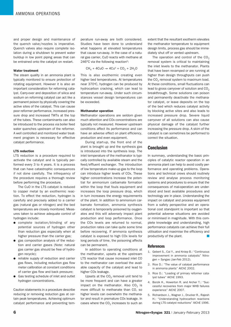
Fig 8: Photo of reduced particle size of HTS catalyst after exposure to extreme temperatures caused by air introduction to the HTS reactor
Fig 9: Photo of fused inert ball, floating screen and catalyst removed from the HTS following exposure to air and extreme temperatures
a 2.5% lower than average tube flow rate can result in an 4-6°C hotter tube wall tem-perature3. Further experience has shown that tube wall temperatures in the area of a catalyst void are about 16-28°C hotter than the surrounding area of the tube.
The impact of plant operations on catalystMany catalyst failures are the result of poor operation or operational upsets. To illustrate the significant potential negative impacts, a number of different examples for various catalytic services are discussed below.
Reduced/pyrophoric catalystCatalysts are often in the reduced metal state during operation in HDS, HTS, LTS, methanator and ammonia synthesis reac-tors. Exposure to air can result in spontane-ous ignition with extremely high localised temperatures causing catalyst failure, fusing and equipment damage. For turna-rounds and longer shut-down periods, ensuring a continuous positive pressure inert blanket is one routine monitoring item. Discharging of pyrophoric catalyst without first oxidising it must be done under nitro-gen with precautions taken to avoid ingress of air to the vessel by a chimney effect. In cases where repair work is required around vessels without adequate isolation, the risk is particularly high and continuous nitrogen purge is necessary. It should be noted that without flow through the catalyst bed, tem-perature measurements do not accurately represent the bed temperatures nor do they detect localised peak temperatures. They can, however, give some indication or warning of an issue.
Complete isolation of the air flow to the secondary reformer is required in a sec-ondary reformer trip to protect downstream catalysts. In one incident at a 1,700 short t/d ammonia plant in North America, the HTS catalyst performance was greatly affected following an upset during start-up of the secondary reformer. A high pres-sure air flow condition resulted in air to the HTS for a short duration. The event occurred relatively fast and other events were occurring so it was not even noticed by the operations team.
Shortly after stabilising plant rates, however, the performance of the charge in terms of CO leakage, while acceptable to allow operation, was higher than expected. After approximately a year on-stream, the decision was made to unload the catalyst during a shut-down. Inspection of the reac-tor showed that the overall outage from the manway had increased by over 0.9 m and that in a particular area of the bed the cat-alyst particle size was reduced from 6x6 mm to roughly 3x3 mm. The support balls were also found fused to melted screen pieces which in turn were fused to cata-lyst. For this level of shrinkage and fusion to occur it is estimated that temperatures must have exceeded 870°C. It is important to note that despite this significant temper-ature exposure, the Clariant catalyst was still able to achieve an acceptable level of performance with no pressure drop issues. (Figs 8 and 9)
Impact of water on catalystWater can affect the integrity of all cata-lysts and in some cases can lead to cata-strophic incidents. Water entrainment
during start-up of the primary reformer can lead to instantaneous flashing at the hot catalyst releasing enough energy to rupture reformer tubes. Water entrainment can occur when low point drains are plugged or not used during shutdown and start-up.
HTS and LTS are particularly at risk due to their location downstream of the HP boiler, quenches and temperature controls. When water comes in contact with catalyst, cata-lyst breakage and increased pressure drop results from water vaporising out of the cata-lyst pores at a faster rate than the porosity of the catalyst will allow. The HTS catalyst is very susceptible to leaks from the upstream HP boiler which are almost inevitable during a plant’s life. Clariant’s HTS ShiftMax
® cata-
lyst was able to survive major boiler leaks at the 1,600 short t/d Terra plant4. In this case, the HTS was flooded with water from a major boiler failure and a dry out proce-dure was successfully implemented under the direction of Clariant. Besides the effect of wetting the catalyst, accumulated boiler solids from boiler leaks can also increase the catalyst’s pressure drop and create poor gas distribution issues. The impact of water and boiler solid carryover can be minimised by using a high voidage inert top layer.
During operational upsets, temperature controller swings can lower the inlet tem-perature of the shift converters below the dew point and wet the catalyst. Operating the LTS at an inlet temperature 17-22°C above dew point can reduce this potential. Boiler feed water quenches are normally installed upstream of shift converters in order to control inlet temperature as well as lower the CO equilibrium. Atomisation is critical to prevent wetting the catalyst
AmmoniA operAtions
6� Nitrogen+Syngas 321 | January - February 2013
extent that the resultant exotherm elevates the methanator temperature to equipment design limits, process gas should be imme-diately shut off or vented upstream.
The operation and control of the CO2 removal system is critical to maintaining the inlet levels to the methanator. Plants that have been revamped or are running at higher than design throughputs can push the CO2 removal system to maximum load. At these conditions, small fluctuations can lead to gross carryover of solution and CO2 breakthrough. Some solutions can poison and permanently deactivate the methana-tor catalyst, or leave deposits on the top of the bed which reduces catalyst activity by blocking active sites and also leads to increased pressure drop. Severe liquid carryover of all solutions can also cause physical damage of the catalyst further increasing the pressure drop. A skim of the catalyst is can sometimes be performed to correct the situation.
ConclusionIn summary, understanding the basic prin-ciples of catalytic reactor operation in an ammonia plant can help to avoid costly per-formance and operating problems. Opera-tions and technical crews should routinely review and analyse process monitoring systems and procedures to ensure that the consequences of mal-operation are under-stood and best available procedures and technology are in place. Understanding the impact on catalyst and process equipment from a safety perspective and an opera-tional cost standpoint is important so that potential adverse situations are avoided or minimised in magnitude. With this com-plete knowledge and understanding, high performance catalysts can achieve their full utilisation and maximise the efficiency and productivity of the plant. n
References1. Gebert S., Cai Y,. and Kniep B.: “Continuous
improvement in ammonia catalysts” Nitro-gen + Syngas (Jan-Feb 2012).
2. Rice D.: “The value of catalyst performance in ammonia plants” AIChE 2002.
3. Rice D.: “Loading of primary reformer cata-lyst tubes” AIChE 1993.
4. Borzik K., Howerton R. and Archer T.: “Suc-cessful recoveries from major WHB failures experience” AIChE 2007.
5. Richardson J., Wagner J., Drucker R., Rajesh H.: “Understanding hydrocarbon reactions during LTS catalyst reductions” AIChE 1996.
and proper design and maintenance of the quench valve/nozzles is imperative. Quench valves also require complete iso-lation during a shutdown to prevent water buildup in low point piping areas that can be entrained onto the catalyst on restart.
Water treatmentThe steam quality in an ammonia plant is typically monitored to ensure protection of rotating equipment. However it is also an important consideration for reforming cata-lyst. Carry-over and deposition of silica and sodium on reforming catalyst can act like a permanent poison by physically covering the active sites of the catalyst. This can cause poor reformer performance, increased pres-sure drop and increased TWTs at the top of the tubes. These contaminants can also be introduced to the process via boiler feed water quenches upstream of the reformer. A well controlled and monitored water treat-ment program is necessary for effective catalyst performance.
LTS reductionLTS reduction is a procedure required to activate the catalyst and is typically per-formed every 3 to 4 years. It is a process that can have catastrophic consequences if not done carefully. The infrequency of the procedure requires a thorough review before performing the procedure.
The CuO in the LTS catalyst is reduced to copper metal by an exothermic reac-tion. To effect the reduction, hydrogen is carefully and precisely added to a carrier gas (natural gas or nitrogen) and the bed temperatures are closely monitored. Meas-ures taken to achieve adequate control of hydrogen include:l complete isolation/blinding of any
potential sources of hydrogen other than reduction gas especially when at higher pressure than the carrier gas;
l gas composition analysis of the reduc-tion and carrier gases (Note: natural gas carrier gas should be free of hydro-gen recycle);
l reliable supply of reduction and carrier gas flows, including reduction gas flow meter calibration at constant conditions of carrier gas flow and back pressure;
l Gas testing schedule of inlet and outlet hydrogen concentrations.
Caution statements in a procedure describe reducing or removing reduction gas at cer-tain peak temperatures. Achieving optimum catalyst performance and preventing tem-
perature run-away are both considered. Studies have been done to understand what happens at elevated temperatures that cause run-away. In the case of a natu-ral gas carrier, CuO reacts with methane at 246°C via the following reaction5:
CH4 + 4CuO → 4Cu0 + CO2 + 2H2O
This is also exothermic creating even higher bed temperatures. At temperatures near 370oC, hydrogen can be produced by hydrocarbon cracking, which can lead to temperature run-away. Under such circum-stances vessel design temperatures can be exceeded.
Methanator operationMethanator operations are seldom given much attention and COx concentrations are typically not measured. However upstream conditions affect its performance and can have an adverse effect on plant efficiency, production and even equipment.
During start-up, the front end of the plant is brought up and the synthesis gas is introduced into the synthesis loop. The inlet temperature of the methanator is typi-cally controlled by available steam and the feed/effluent exchanger. The introduction of low temperature make-up gas to the loop can introduce higher levels of COx. These higher concentrations increase the poten-tial for ammonium carbamate formation within the loop that fouls equipment and increases the loop pressure drop, which in turn increases the energy requirements of the plant. In addition to ammonium car-bamate formation, ammonia synthesis catalyst is temporarily poisoned by oxygen-ates and this will adversely impact plant production and loop performance. Once the COx levels are returned to normal, production rates can take quite some time before recovering. If ammonia synthesis catalyst is exposed to high COx levels for long periods of time, the poisoning affects can be permanent.
In addition to operating conditions at the methanator, upsets at the upstream LTS reactor that cause increased inlet CO to the methanator can overload the avail-able capacity of the catalyst and lead to higher COx leakage.
Upsets at the CO2 removal unit tend to be more frequent and can have a greater impact on the methanator. Also CO2 is more difficult to methanate than CO, so higher levels can overwhelm the methana-tor and result in premature COx leakage. In cases where the CO2 increases to such an