neotωist design study of a kinetic …iaaweb.org/iaa/scientific...
TRANSCRIPT

NEOShield-2 Science and Technology for Near-Earth Object Impact Prevention
This project has received funding from the European Union’s Horizon 2020 research and innovation programme under grant agreement No 640351.
Kilian A. Engel, Mattia Pugliatti, Line Drube, Juan L. Cano, Daniel Hestroffer, Simon Delchambre, Tobias Ziegler, Albert Falke, Ulrich Johann, Alan Harris
Tokyo, 17 May 2017 IAA-PDC-17-05-13
NEOTωIST – DESIGN STUDY OF A KINETIC IMPACTOR DEMONSTRATION MISSION FEATURING NEO SPIN
CHANGE AND OBSERVER SUB-SPACECRAFT

Outline
• Introduction
• Mission Architecture and Implementation Options
• Observation geometry
• Impactor concept
• Flyby module concept
• Chaser concept
• Concluding remarks
2
Introduction
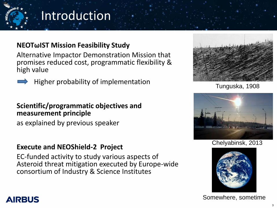
NEOTωIST Mission Feasibility Study
Alternative Impactor Demonstration Mission that promises reduced cost, programmatic flexibility & high value
Higher probability of implementation
Scientific/programmatic objectives and measurement principle
as explained by previous speaker
Execute and NEOShield-2 Project
EC-funded activity to study various aspects of Asteroid threat mitigation executed by Europe-wide consortium of Industry & Science Institutes
3
Tunguska, 1908
Chelyabinsk, 2013
Somewhere, sometime
Mission Architecture
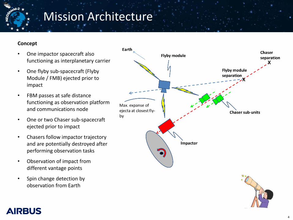
Concept
• One impactor spacecraft also functioning as interplanetary carrier
• One flyby sub-spacecraft (Flyby Module / FMB) ejected prior to impact
• FBM passes at safe distance functioning as observation platform and communications node
• One or two Chaser sub-spacecraft ejected prior to impact
• Chasers follow impactor trajectory and are potentially destroyed after performing observation tasks
• Observation of impact from different vantage points
• Spin change detection by observation from Earth
4

Mission Architecture & Implementation Options
5
Vehicle Functions Information generated
Impactor • End game GNC • Interplanetary carrier
• Impact location (Navigation data)
Flyby module • Observation of ejecta geometry (camera + radiometer)
• Reception & downlink of data from all S/C
• Direction of overall ejecta cloud vector
• Ejecta dynamics & optical density
• Radiometry of blast
Chaser(s) • Observation of impact crater • (Long range observation of
ejecta)
• Constraint on ejecta volume / crater volume
O1
O2
O3
Observation geometry of flyby
6
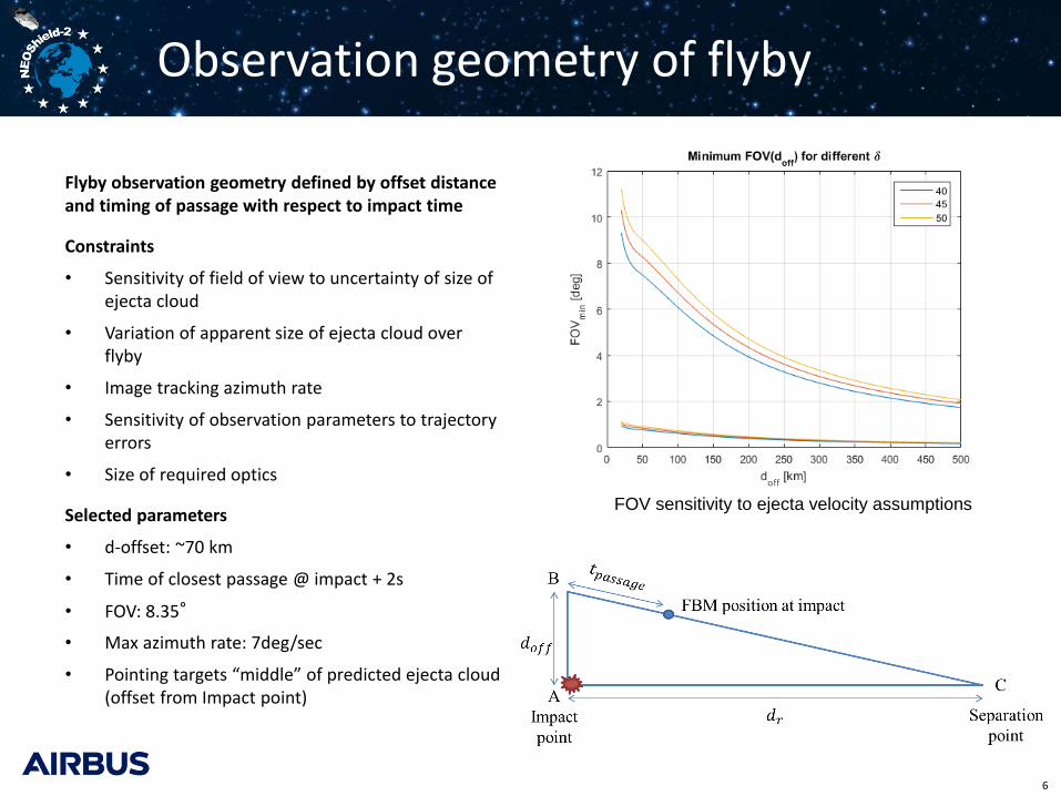
Flyby observation geometry defined by offset distance and timing of passage with respect to impact time
Constraints
• Sensitivity of field of view to uncertainty of size of ejecta cloud
• Variation of apparent size of ejecta cloud over flyby
• Image tracking azimuth rate
• Sensitivity of observation parameters to trajectory errors
• Size of required optics
Selected parameters
• d-offset: ~70 km
• Time of closest passage @ impact + 2s
• FOV: 8.35°
• Max azimuth rate: 7deg/sec
• Pointing targets “middle” of predicted ejecta cloud (offset from Impact point)
FOV sensitivity to ejecta velocity assumptions
Visualisation of Flyby Observation
7
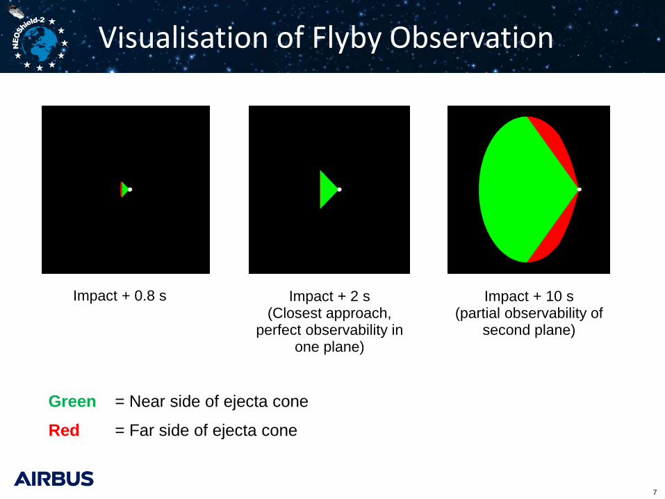
Impact + 0.8 s Impact + 2 s (Closest approach,
perfect observability in one plane)
Impact + 10 s (partial observability of
second plane)
Green = Near side of ejecta cone
Red = Far side of ejecta cone
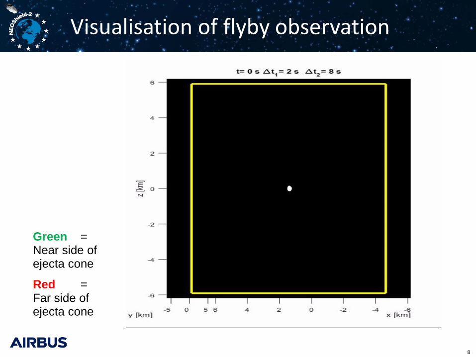
Visualisation of flyby observation
8
Green = Near side of ejecta cone
Red = Far side of ejecta cone

• Small Mission Module based on updated Don Quijote design
• Propulsion using slightly modified existing propulsion module from Lisa Pathfinder
• Propulsion module contributes to impacting mass • Visual GNC for final approach • Launch on VEGA
Impactor and stack overview
9
Dry [kg] Wet [kg]
Fly-by Module 104.1 104.6
Chaser 25.7 26.2
Impactor Mission Module 263 263
Propulsion module (incl. resid.) 280 1420
Stack 673 1814
Stack at launch incl. adapter 1929
Delivered mass w/o prop. mod. 394
Min. impacting mass 543
Vehicle stack mass synopsis

Flyby module drivers & payload
10
Design drivers
• High quality imaging of ejecta cloud during high velocity pass
• Imaging geometry in light of uncertainties in approach trajectory
• Data buffering & transmission for entire constellation
• Size and mass constraints imposed by mission concept
• Mission cost
• Required reliability
• Deep space environment
Payload • Medium angle camera • Field of view: 8° • Aperture: ~ 9 cm • Detector: 2048 x 2048 pixel • Max. resolution at 70 km: 5m • Field of view pointing: pointing mirror • Image targeting based on visual
navigation using payload camera • Non-imaging radiometer
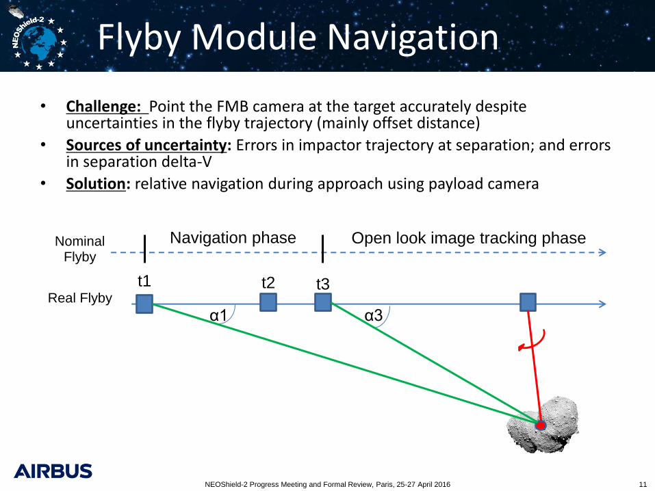
Flyby Module Navigation
NEOShield-2 Progress Meeting and Formal Review, Paris, 25-27 April 2016 11
• Challenge: Point the FMB camera at the target accurately despite uncertainties in the flyby trajectory (mainly offset distance)
• Sources of uncertainty: Errors in impactor trajectory at separation; and errors in separation delta-V
• Solution: relative navigation during approach using payload camera
Nominal Flyby
Real Flyby
t1
α1
t2
α3
t3
Navigation phase Open look image tracking phase
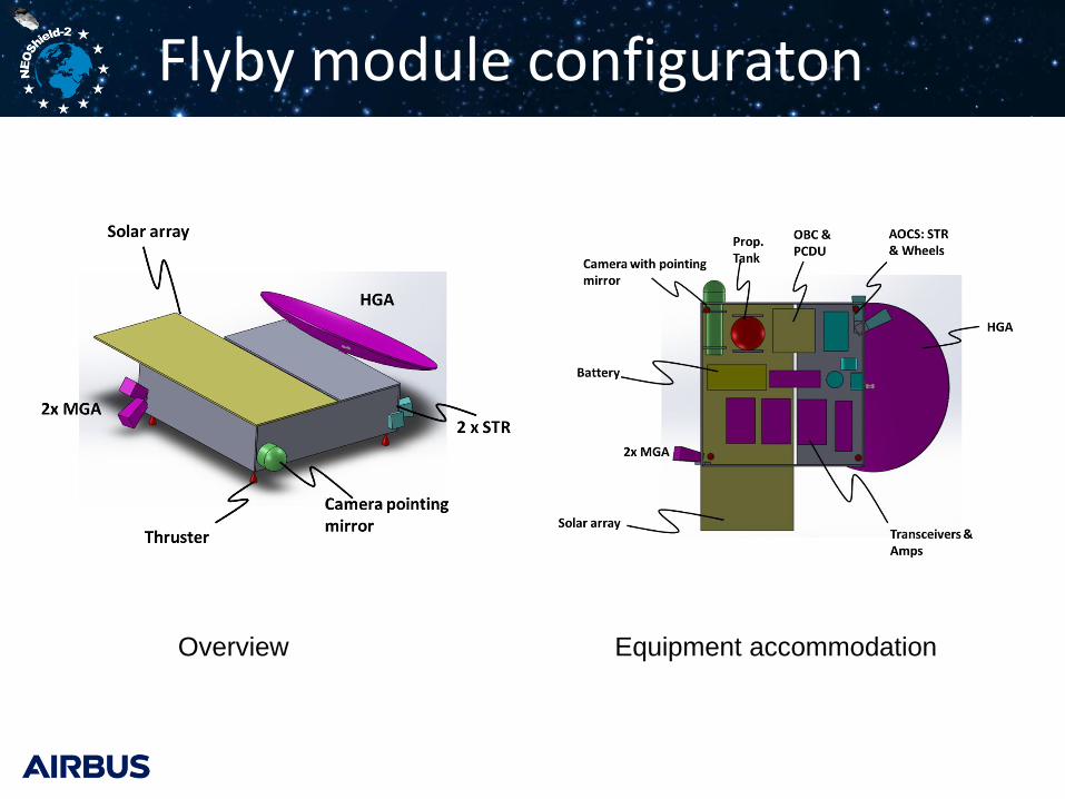
Flyby module configuraton
Overview Equipment accommodation

Flyby module preliminary specs
Item Description
Mass Dry/ Wet: 104.1 / 104.6 kg
Power DC: 100 W S/A : 0.75 m² Battery: 150 Wh (usable)
Dimensions Bus structure: 100 x 100 x 25 cm³
Power and data handling
PROBA-NEXT avionics integrated power and data handling, >1 Gbit mass memory
Comms. Earth-link: X-band, 1m HGA, 20 W RF, 50 kb/s Impactor link: X-band, MGA, Rx only, < 10 Mbit/s Chaser link: X-band, MGA, Rx only, ~ 20 Mbit/s
AOCS 3-axis stabilised 2 x STR (DTU Micro ASC) 2x Coarse sun sensors 3 x Micro-wheels, 0.42 Nms (e.g. SSTL) IMU (DTU, int. with STR electronics) RCS: 4 x cold gas thrusters for momentum management (0.5 kg of N2)

Chaser concept
14
Design drivers
• Small size of main target (crater)
• Uncertainty in imaging geometry
• Real-time transmission of imaging data before vehicle destruction
• Large delta-V for separation from Impactor
• Mission cost and mass constraints
• Deep space environment

Chaser concept
15
Item Description
Mass Dry/Wet: 25.7 / 26.2 kg
Power DC: 40 W Battery: 60 Wh (usable)
Dimensions 20 x 30 x 10 cm³ (TBC) Payload Medium angle camera
Field of view: 16° Aperture: still to be determined Detector: 2048 x 2048 pixel Max. resolution: 4m @ 30 km, 2m @ 15 km No active target tracking
Power & data Cube-sat/ small sat equipment (details still to be selected) Comms. Link to FBM: X-band, MGA, TX only, ~ 20 Mbit/s
AOCS Stabilization along velocity direction with single uncontrolled momentum wheel, spun up before ejection from Impactor
Propulsion Hydrazine, single thruster in anti-velocity direction, stabilization with momentum wheel, dV capability 70 m/s
Thermal Heaters & radiators, non-stationary design for terminal phase possible

Concluding remarks
16
NEOTωIST Mission Concept addresses objectives of Kinetic Impactor Demo Mission at reduced cost and with flexible implementation options
Advantages achieved by
• New measurement principle for quantifying the achieved momentum transfer to target
• Replacing large rendezvousing reconnaissance spacecraft with small sub-spacecraft
Current snapshot of feasibility work shows no show stopper
Future work & iterations on
• Refinement of the payload
• Refinement of combined AOCS image targeting concept
• Equipment selection and overall vehicle design
• Refinement of communications and data management

NEOShield-2 Science and Technology for Near-Earth Object Impact Prevention
This project has received funding from the European Union’s Horizon 2020 research and innovation programme under grant agreement No 640351.
Thank you for your attention!
Questions?
www.NEOShield.eu
www.facebook.com/NEOShield
@NEOShieldTeam
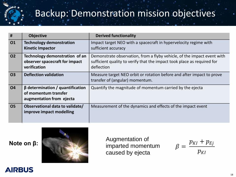
Backup: Demonstration mission objectives
18
# Objective Derived functionality
O1 Technology demonstration Kinetic Impactor
Impact target NEO with a spacecraft in hypervelocity regime with sufficient accuracy
O2 Technology demonstration of an observer spacecraft for impact verification
Demonstrate observation, from a flyby vehicle, of the impact event with sufficient quality to verify that the impact took place as required for deflection
O3 Deflection validation Measure target NEO orbit or rotation before and after impact to prove transfer of (angular) momentum.
O4 β determination / quantification of momentum transfer augmentation from ejecta
Quantify the magnitude of momentum carried by the ejecta
O5 Observational data to validate/ improve impact modelling
Measurement of the dynamics and effects of the impact event
Note on β: 𝛽 = 𝑝𝐾𝐼 + 𝑝𝐸𝑗
𝑝𝐾𝐼
Augmentation of imparted momentum caused by ejecta
Backup: Measurement principles
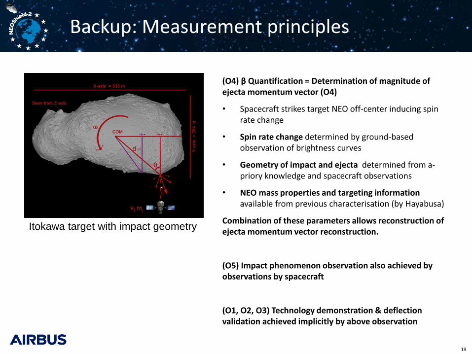
(O4) β Quantification = Determination of magnitude of ejecta momentum vector (O4)
• Spacecraft strikes target NEO off-center inducing spin rate change
• Spin rate change determined by ground-based observation of brightness curves
• Geometry of impact and ejecta determined from a-priory knowledge and spacecraft observations
• NEO mass properties and targeting information available from previous characterisation (by Hayabusa)
Combination of these parameters allows reconstruction of ejecta momentum vector reconstruction.
(O5) Impact phenomenon observation also achieved by observations by spacecraft
(O1, O2, O3) Technology demonstration & deflection validation achieved implicitly by above observation
19
Itokawa target with impact geometry