navigation system - ca clasecaclase.co.uk/.../11/7000-118-301f1r5-supreme-navigation-system-… ·...
TRANSCRIPT

OPERATION & INSTALLATION MANUAL
Saab TransponderTech
R5 SUPREME
Navigation System

This page is intentionally empty

R5 SUPREME - Navigation System
SYSTEM OVERVIEW
7000 118-301, F1 Page 3
i Copyright
The entire contents of this manual and its appendices, including any future updates and modifications, shall remain the property of Saab TransponderTech AB at all times. The contents must not, whether in its original form or modified, be wholly or partly copied or reproduced, nor used for any other purpose than the subject of this manual.
Saab TransponderTech AB, SWEDEN
ii Disclaimer
While reasonable care has been exercised in the preparation of this manual, Saab TransponderTech AB shall incur no liability whatsoever based on the contents or lack of contents in the manual.
iii Software
This manual reflects the capabilities of R5 SUPREME Control and Display Unit software 1.1.14.
iv Manual Part Number and Revision
Part number 7000 118-301, revision F1.
v Safety Instructions
Note the following compass safe distances:
Equipment vi Standard magnetic
compass
vii Steering magnetic
compass
viii R5 SUPREME CDU 0.75 m 0.5 m
R4 Navigation Sensor 0.6 m 0.4 m
ix Disposal Instructions
Broken or unwanted electrical or electronic equipment parts shall be classified and handled as ‘Electronic Waste’. Improper disposal may be harmful to the environment and human health. Please refer to your local waste authority for information on return and collection systems in your area.
x Contact Information
For installation, service, ordering info and technical support please contact your local Saab TransponderTech representative.

R5 SUPREME - Navigation System
SYSTEM OVERVIEW
7000 118-301, F1 Page 4
A list of dealers and service stations can be found on the corresponding product page at http://saab.com/security/maritime-traffic-management/traffic-management/

R5 SUPREME - Navigation System
SYSTEM OVERVIEW
7000 118-301, F1 Page 5
TABLE OF CONTENTS
1 System Overview ........................................................................... 8
1.1 Product Description ............................................................................................... 8
1.2 Main Features ....................................................................................................... 10
2 Installation .................................................................................... 11
2.1 Unpacking the Equipment .................................................................................... 11
2.2 Equipment Installation Environment ................................................................... 13
2.3 Installation Cables ................................................................................................ 14
2.1 System interconnection overview ....................................................................... 18
2.2 Installation Procedure .......................................................................................... 20
2.3 Mount the R5 SUPREME Control and Display Unit (CDU) ................................. 21
2.4 Mount the R4 Navigation Sensor ......................................................................... 25
2.5 Mount the GNSS or DGNSS Navigation Antenna ............................................... 26
2.6 Mount the R5 NAV Junction Box (if applicable) ................................................. 28
2.7 System interconnection without R5 NAV Junction box ..................................... 32
2.8 Electrical Installation ............................................................................................ 34
3 Concepts and Terminology ......................................................... 37
4 Configuration ............................................................................... 39
4.1 Configuration Wizard............................................................................................ 39
4.2 Configuration Parameters .................................................................................... 41
5 Operation ...................................................................................... 57
5.1 Buttons and LEDs on R5 SUPREME CDU ........................................................... 57
5.2 LEDs on R4 Navigation Sensor ........................................................................... 59
5.3 Change Settings of a Parameter .......................................................................... 59
5.4 System Menus - Tree View ................................................................................... 61
5.5 Navigating in Menus ............................................................................................. 62
5.6 Alarm and Alert Pop-ups ...................................................................................... 62
5.7 Status Bar.............................................................................................................. 63
5.8 Navigate Menu ...................................................................................................... 64
5.9 Voyage Menu ........................................................................................................ 75
5.10 Tidal Predictions ................................................................................................... 89
5.11 Status Menu .......................................................................................................... 96
5.12 DGPS Messages (DGPS or DGNSS version only) ............................................ 103
5.13 Update Software ................................................................................................. 103

R5 SUPREME - Navigation System
SYSTEM OVERVIEW
7000 118-301, F1 Page 6
5.14 Factory reset ....................................................................................................... 104
5.15 Save/Load Config to/from USB memory ........................................................... 105
6 Slave Displays and Redundant Systems ................................. 108
6.1 R5 SUPREME Navigation System with Slave Display ...................................... 108
6.2 Redundant Navigation Systems ........................................................................ 111
6.3 Synchronized Items ............................................................................................ 112
7 Software Upgrade ...................................................................... 114
7.1 Upgrade R5 SUPREME CDU Software .............................................................. 114
8 Technical Specifications ........................................................... 115
8.1 R5 SUPREME CDU .............................................................................................. 115
8.2 R4 Navigation Sensor ......................................................................................... 116
8.3 R5 NAV Junction Box ......................................................................................... 117
9 Troubleshooting ......................................................................... 118
9.1 Troubleshooting with the CDU Front Panel LED’s ........................................... 118
9.2 Troubleshooting with Alarm Messages............................................................. 119
9.3 Troubleshooting via the CDU ............................................................................. 121
9.4 Contacting Support ............................................................................................ 122
10 Serial Communication Interfaces ............................................. 123
10.1 Input Sentences .................................................................................................. 123
10.2 Output Sentences ............................................................................................... 123
11 Interpretations of Output Sentences ........................................ 126
11.1 Output Sentences, GPS ...................................................................................... 126
11.2 Output Sentences, Navigation ........................................................................... 132
11.3 Output Sentences, Old NMEA Versions ............................................................ 136
12 Interpretations of Input Sentences ........................................... 137
12.1 Input Sentences .................................................................................................. 137
12.2 Input Sentences, Old NMEA Versions ............................................................... 139
13 Alternate System Setups ........................................................... 141
13.1 Redundant Navigation Systems ........................................................................ 141
13.2 Navigation System with Slave Displays ............................................................ 141
13.3 Combined AIS and Navigation system setup ................................................... 142
14 Electrical Interfaces ................................................................... 144
14.1 CDU Interfaces: ................................................................................................... 144
14.2 R4 Navigation Sensor interfaces ....................................................................... 148
14.3 R5 NAV Junction box Interfaces ........................................................................ 151

R5 SUPREME - Navigation System
SYSTEM OVERVIEW
7000 118-301, F1 Page 7
15 Mechanical Drawings ................................................................. 154
15.1 CDU Physical Size and Mechanical Drawing .................................................... 154
15.2 CDU Panel Mount Cutout Hole dimensions ...................................................... 155
15.3 CDU Mounting Frame cutout and dimensions .................................................. 156
15.4 Sensor Physical Size and Mechanical Drawing ................................................ 157
15.5 R5 NAV Junction Box Physical Size and Mechanical Drawing ....................... 158
15.6 MGA-3 / MGL-5 Antenna Physical Size and Mechanical Drawing ................... 159
16 Glossary ..................................................................................... 160
17 Appendix B - License ................................................................. 162
17.1 Copy of the GNU General Public License ......................................................... 162

R5 SUPREME - Navigation System
SYSTEM OVERVIEW
7000 118-301, F1 Page 8
1 SYSTEM OVERVIEW
1.1 Product Description
The R5 SUPREME Navigation System is available in several configurations. All current R5 Navigation systems are IMO type approved, and include an R5 SUPREME Control and Display Unit (R5 CDU from here on).
The R5 CDU has a seven inch colour touch display and provides a graphical interface to the system. Via the R5 SUPREME CDU it is possible to create, edit and modify routes and waypoints, navigate following a route, plot the route, view sensor data, configure the system as well as supervise the system status. It is also possible to connect the R5 CDU to an R5 SUPREME AIS Transponder, for a combined AIS and navigation solution.
There are currently four types of R4 Navigation sensors, with options of GLONASS and IALA beacon additions to the GPS receiver.
The R4 GPS Navigation Sensor features a high-precision L1 GPS receiver, capable of receiving WAAS, EGNOS and MSAS differential corrections. The R4 DGPS Navigation Sensor additionally includes a dual channel beacon receiver for reception of IALA radio beacon DGPS corrections.
The upgraded R4 GNSS and R4 DGNSS sensors feature a 270 channel combined L1 GPS and L1 GLONASS receiver with dual channel SBAS-tracking, offering up to 60 cm accuracy under optimal conditions. The combined use of GLONASS and GPS navigation increases robustness and reliability of the navigation solution.
The R4 GPS/GNSS Sensor configurations use the MGA-3 GNSS antenna, while the R4 DGPS/DGNSS sensor configurations are designed to operate with the MGL-5 combined GNSS/Beacon antenna.
Together the R5 CDU and the R4 Navigation Sensor provides four configurable serial user ports, of which three are bidirectional and one used only for output of data (User Port 2). User Port 3 and User Port 4 are high speed ports that can be used in “high-speed craft” installations. There are also a binary Speed log, an Alarm Output port as well as an Alarm Acknowledge input port.

R5 SUPREME - Navigation System
SYSTEM OVERVIEW
7000 118-301, F1 Page 9
R4
Sensor
(D)GNSS
AntennaR5 SUPREME CDU

R5 SUPREME - Navigation System
SYSTEM OVERVIEW
7000 118-301, F1 Page 10
1.2 Main Features
Signal integrity monitoring calculations (RAIM) according to the IEC 61108-1 (2nd edition) standard. The RAIM function detects whether expected user defined navigation accuracy is achieved.
Reception and use of differential corrections from SBAS, from the serial interface in RTCM SC-104 format and, in the DGPS configuration, from IALA radio beacons.
GNSS configurations feature combined GPS and GLONASS navigation for increased reliability
Automatic or manual SBAS satellite selection modes.
Navigational views with next waypoint information and cross-track error visualization.
Display of latitude, longitude, speed over ground and course over ground.
Capability to handle and store up to 4000 individually named waypoints and up to 128 different routes.
Man Over Board (MOB) and Event Mark functionality.
Two trip log counters with indication of average speed and accumulated time during motion.
Anchor Watch position deviation alarm.
Scheduled Alerts, user configurable time alarms and time to ETA alarms.
Time frame related to UTC or user defined local offset.
Synchronization of waypoint/route database and settings with external R5 Navigation systems in redundant installations.
Support for additional view only R5 SUPREME CDUs connected in slave mode.
Input and output of IEC 61162-1 sentences configurable on sentence level and per port, providing control over interpreted, ignored and transmitted sentences.
Output of GPS positioning information on User ports, enabling external systems to connect to and use the GPS information from the R4 Navigation Sensor.

R5 SUPREME - Navigation System
INSTALLATION
7000 118-301, F1 Page 11
2 INSTALLATION
2.1 Unpacking the Equipment
The R5 Navigation System consists of the R5 SUPREME CDU, a Navigation sensor, a Navigation sensor antenna and a number of accessories and optional additions.
Each delivery can be different depending on what options and accessories are ordered. Below is a list of the most common available parts.
NOTE: This is not a list of supplied parts, as contents may vary for each order depending on user needs
Name Part number
R5 SUPREME Control and Display Unit 7000 118-530
R5 Power Cable 7000 118-077
R5 Signal cable DSUB-OPEN 2m
(For use without Junction Box)
7000 118-078
R5 Signal cable DSUB-DSUB 2m
(For Junction Box connection)
7000 118-286
R5 NAV Junction Box 7000 118-121
R4 Navigation Sensor Power and Signal
Cable
(Used without Junction Box)
7000 109-011
R5 NAV Sensor Cable
(For Junction Box connection)
7000 118-122
Navigation Sensor options
R4 GPS Navigation Sensor
R4 DGPS Navigation Sensor
R4 GNS Navigation Sensor
(GPS+GLONASS)
R4 DGNSS Navigation Sensor
(DGPS+GLONASS)
7000 109-141
7000 109-140
7000 109-181
7000 109-180
Navigation Sensor Antennas
MGA-3 GNSS Antenna
MGL-5 DGNSS Antenna (Combined GNSS
/ Beacon)
7000 000-554
7000 000-555

R5 SUPREME - Navigation System
INSTALLATION
7000 118-301, F1 Page 12
Alarm relay unit including socket 7000 100-132
R5 SUPREME AIS Transponder
(For combined AIS/NAV configuration)
7000 118-540
R5 Signal cable DSUB-DSUB 2m
(Transponder to AIS Junction Box)
7000 118-286
R5 AIS Junction Box
(For combined AIS/NAV configuration)
7000 118-120
AIS VHF Antenna BA 1012
(for R5 SUPREME AIS Transponder)
7000 000-077
AIS AT575-68 GPS Antenna
(for R5 SUPREME AIS Transponder)
7000 000-135
AIS MA700 GPS Antenna, incl. 10m cable
(for R5 SUPREME AIS Transponder)
7000 000-485
AIS AC Marine GPS/VHF Antenna with
diplexer
(for R5 SUPREME AIS Transponder)
7000 000-435
R5 Ethernet Cable 5m
IEC 60332-1, LSHF
7000 000-525
Table 1 - R5 SUPREME Navigation System and accessories
Note 1: The R5 NAV Junction Box includes an alarm relay with lower power rating than alarm relay 7000 100-132.

R5 SUPREME - Navigation System
INSTALLATION
7000 118-301, F1 Page 13
2.2 Equipment Installation Environment
The table below lists the IEC 60945 equipment classification for the system.
Name Part number IEC 60945
installation category
R5 SUPREME CDU 7000 118-530 Protected
R5 NAV Junction box 7000 118-121 Protected
R4 GPS Navigation Sensor 7000 109-141 Protected
R4 DGPS Navigation Sensor 7000 109-140 Protected
R4 GNSS Navigation Sensor 7000 109-181 Protected
R4 DGNSS Navigation Sensor 7000 109-180 Protected
MGA-3 GNSS Antenna 7000 000-554 Exposed
MGL-5 Combined GNSS / Beacon
Antenna
7000 000-555 Exposed

R5 SUPREME - Navigation System
INSTALLATION
7000 118-301, F1 Page 14
2.3 Installation Cables
The following cables are used to install the standard R5 SUPREME Navigation System.
2.3.1 R5 Signal Cable DSUB-OPEN
Marking: 7000 118-078, C1
Application: R5 CDU I/O port to open ends
Type: Shielded Twisted Pair 24 x 0.33 mm2
Length: 2 m
Connector: 26-pole H.D.D-SUB (female)
Flame retardant: IEC60332-1
Colour coding: DIN 47100
Interconnection Specification:
D-SUB Pin Open End colour
1 White
2 Brown
3 Green
4 Yellow
5 Grey
6 Pink
7 Blue
8 Red
9 Black
10 Violet
11 Grey / Pink
12 Red / Blue
13 White / Green
14 Brown / Green
15 White / Yellow
16 Yellow / Brown
17 White / Grey
18 Grey / Brown
19 White / Pink
20 Pink / Brown
21 White / Blue
22 Brown / Blue
23 White / Red
24 Brown / Red
Table 2 – R5 Signal Cable DSUB-OPEN interconnection

R5 SUPREME - Navigation System
INSTALLATION
7000 118-301, F1 Page 15
2.3.2 R5 Signal Cable DSUB-DSUB (used with R5 NAV Junction Box)
Marking: 7000 118-286
Application: R5 CDU I/O port to R5 NAV Junction box.
Type: Shielded Twisted Pair x 0.33 mm2
Length: 2 m
Diameter: 11 mm
Connector: 2 x 26-pole H.D.D-SUB (female to male)
Flame retardant: IEC60332-1
Interconnection: Straight connection on all pins.
2.3.3 R5 Power Cable
Marking: 7000 118-077
Application: R5 CDU power port to R5 NAV Junction box or external power.
Type: Unshielded 4 wire cable x 1.3 mm2
Length: 2 m
Diameter: 6 mm
Connector: ConXall Mini-Con-X 6382-4SG-311 (female) to open ends
Interconnection specification:
Pin Cable Colour
1 Red
2 Black
3 Brown
4 Orange
Table 3 – R5 Power Cable interconnection
R5 SUPREME - Navigation System
INSTALLATION
7000 118-301, F1 Page 16
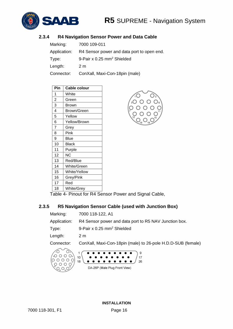
2.3.4 R4 Navigation Sensor Power and Data Cable
Marking: 7000 109-011
Application: R4 Sensor power and data port to open end.
Type: 9-Pair x 0.25 mm2 Shielded
Length: 2 m
Connector: ConXall, Maxi-Con-18pin (male)
Pin Cable colour
1 White
2 Green
3 Brown
4 Brown/Green
5 Yellow
6 Yellow/Brown
7 Grey
8 Pink
9 Blue
10 Black
11 Purple
12 NC
13 Red/Blue
14 White/Green
15 White/Yellow
16 Grey/Pink
17 Red
18 White/Grey
Table 4- Pinout for R4 Sensor Power and Signal Cable,
2.3.5 R5 Navigation Sensor Cable (used with Junction Box)
Marking: 7000 118-122, A1
Application: R4 Sensor power and data port to R5 NAV Junction box.
Type: 9-Pair x 0.25 mm2 Shielded
Length: 2 m
Connector: ConXall, Maxi-Con-18pin (male) to 26-pole H.D.D-SUB (female)

R5 SUPREME - Navigation System
INSTALLATION
7000 118-301, F1 Page 17
2.3.6 R4 Navigation Sensor GNSS Antenna Cable
(Not supplied by Saab TransponderTech)
Type: See section 2.5.2
Length: See section 2.5.2
Connector: TNC (Male)
2.3.7 R5 SUPREME Ethernet Cable
Type: Cat-7, LSZH-FR, IEC 60332-1
Length: 5 m
Diameter: 6,5 mm
Connector: RJ-45
Part number: 7000 000-525
2.3.8 Minimum cable bending radius
When installing the cables the recommended minimum bending radiuses are as follows:
Signal and power cables: 10 times cable diameter
Coaxial cables: 5 times cable diameter

R5 SUPREME - Navigation System
INSTALLATION
7000 118-301, F1 Page 18
2.1 System interconnection overview
The R5 Navigation System can be set up in a number of different ways.
As a standalone navigation system
o One CDU unit, one sensor, one antenna, optional navigation junction box
As a Combined Navigation and AIS system
o Same as above, plus a transponder with additional GNSS and VHF antennas and an AIS junction box.
As multiple redundant navigation systems
o Several instances of the standalone navigation system connected to the same network, configured to synchronize navigation data.
One system with extra Navigation displays in view only mode (Master-Slave Mode)
o One instance of the standalone system, plus additional slave (view only) CDUs connected to the same network.
See Chapter 13 “Alternate System Setups” for system layouts and details of alternate setups.

R5 SUPREME - Navigation System
INSTALLATION
7000 118-301, F1 Page 19
2.1.1 Standalone R5 NAV with Junction Box
The R5 Navigation system is available in a GPS/GNSS or in a DGPS/DGNSS system configuration. The DGPS/DGNSS system features a R4 Navigation sensor and antenna different from the GPS/GNSS system.
In addition it is possible to do the installation with or without the R5 NAV Junction box. If the Junction box is omitted the signal cables shall be of the type with connectors in one end only.
User
Port 1
Speed
Log
Alarm
Relay
User
Port 4
User
Port 3
User
Port 2
Alarm
ACK
R4 Navigation Sensor
(D)GNSS Antenna
R5 NAV Junction Box
4
GP I/O
R5 NAV Sensor Cable
External power 24 VDC
R5 Signal Cable
R5 Power Cable
Figure 1 – Standalone R5 NAV with NAV Junction Box
System
Port
User
Port 1
User
Port 2
Speed
Log
Alarm
Output
RS-422 Ports
User
Port 3
User
Port 4
R4
SensorAlarm
ACK
Binary PortsRS-422 Ports
R4 Nav Signal and Power Cable
R4 Navigation Sensor
(D)GNSS Antenna
24 VDC/1A
External fuse
24 VDC/2A
External fuse
R5 Signal Cable DSUB-OPENR5 Power Cable
Figure 2 – Standalone R5 NAV with NAV Junction Box

R5 SUPREME - Navigation System
INSTALLATION
7000 118-301, F1 Page 20
2.2 Installation Procedure
When installing the R5 SUPREME Navigation System, it is recommended to follow the steps described in this manual. Details of the installation procedure can be found in the coming sections of the manual.
Recommended installation steps:
1) Mount the R5 SUPREME CDU at conning station
2) Mount the R4 Navigation Sensor
3) Mount the alarm relay unit (if applicable)
4) Mount the GNSS antenna
5) If R5 NAV Junction box is used:
a. Connect all external systems and sensors to the R5 NAV Junction Box
b. Mount the R5 NAV Junction Box
c. Connect the R5 SUPREME CDU and the R4 Navigation Sensor to the R5 NAV Junction box
6) If R5 NAV Junction box is NOT used:
a. Mount a custom screw terminal for system interconnection
b. Connect the R5 SUPREME CDU Sensor port to the R4 Navigation Sensor System port
c. Connect external systems
7) For Redundant or Slave display configuration:
a. Connect the CDU to a network, or directly to another CDU using the R5 Ethernet Cable or equivalent.
8) For Combined NAV and AIS configuration:
a. Install the R5 Supreme Transponder as detailed in the R5 Supreme AIS System manual.
b. Connect the CDU directly to the Transponder, or a common Ethernet network, using the R5 Ethernet Cable or equivalent.
9) Apply power to the system and allow the system to power up
10) Follow the CDU System setup, and select System mode corresponding to the current setup. Set network parameters if applicable.
11) Set configuration parameters.
12) For Combined AIS and NAV installation:
a. See R5 Supreme AIS System manual for AIS configuration
13) Configure output sentences for external systems
14) Perform system functional check
R5 SUPREME - Navigation System
INSTALLATION
7000 118-301, F1 Page 21
2.3 Mount the R5 SUPREME Control and Display Unit (CDU)
2.3.1 CDU Location
The R5 SUPREME CDU should be mounted close to the position from which the ship is normally operated, preferably on the bridge console close to the conning position.
When mounting the R5 SUPREME CDU, please consider the following:
The temperature and humidity should be moderate and stable, +15ºC to +35ºC (Operating temperature: -15ºC to +55ºC.)
Select a location away from excessive heat sources
Avoid areas where there is a high flow of humid salt air
Avoid places with high levels of vibrations and shocks
Avoid mounting the R5 SUPREME CDU in direct sunlight. Prolonged exposure to direct sunlight may have adverse effects to the system.
Ensure that there is enough airflow to avoid high ambient temperatures
The units can affect magnetic compasses.
o The minimum compass safe distance from the R5 SUPREME CDU is 0.75 meters to a standard magnetic compass and 0.50 meters to a steering magnetic compass.
2.3.2 R5 SUPREME CDU Mounting Options
The R5 SUPREME transponder and CDU are equipped with power and interface connectors designed to prevent water ingress.
However, the SD, USB and Pilot connectors under the CDU front hatch are protected by the hatch only; the connectors are NOT water proof.
It is therefore recommended to keep the CDU hatch closed when possible. The hatch has a locking mechanism designed to prevent unintentional opening. Depending on installation type it may be desired to keep this hatch locked.
It is recommended to install the system in an environment that is as protected from direct sunlight and water spray as possible. The R5 SUPREME CDU can be mounted in three different ways.
Gimbal mount
Panel mount
Mounting frame panel mount – The CDU can be mounted in a frame that will cover a mounting hole from a previous R4 MKD flush mount installation.
2.3.2.1 CDU Gimbal Mount
The gimbal mount allows for a quick installation, and is suitable for panel as well as ceiling mounting. It will give the benefit of a tilt-able display and the possibility to mount and dismount CDU easily.
The gimbal mount is fastened with four screws in the mounting surface. The CDU is attached to the gimbal mount with two wing knobs.

R5 SUPREME - Navigation System
INSTALLATION
7000 118-301, F1 Page 22
2.3.2.2 Panel Mount
Panel mounting will reduce bridge clutter and reduce the space needed for installation.. A
cutout fitting the CDU profile must be made. See Chapter 15 for dimensions.
The CDU is fastened in place using the pin screw nut and washer nut from the included
mounting kit 7000 118-315.
R5 SUPREME - Navigation System
INSTALLATION
7000 118-301, F1 Page 23
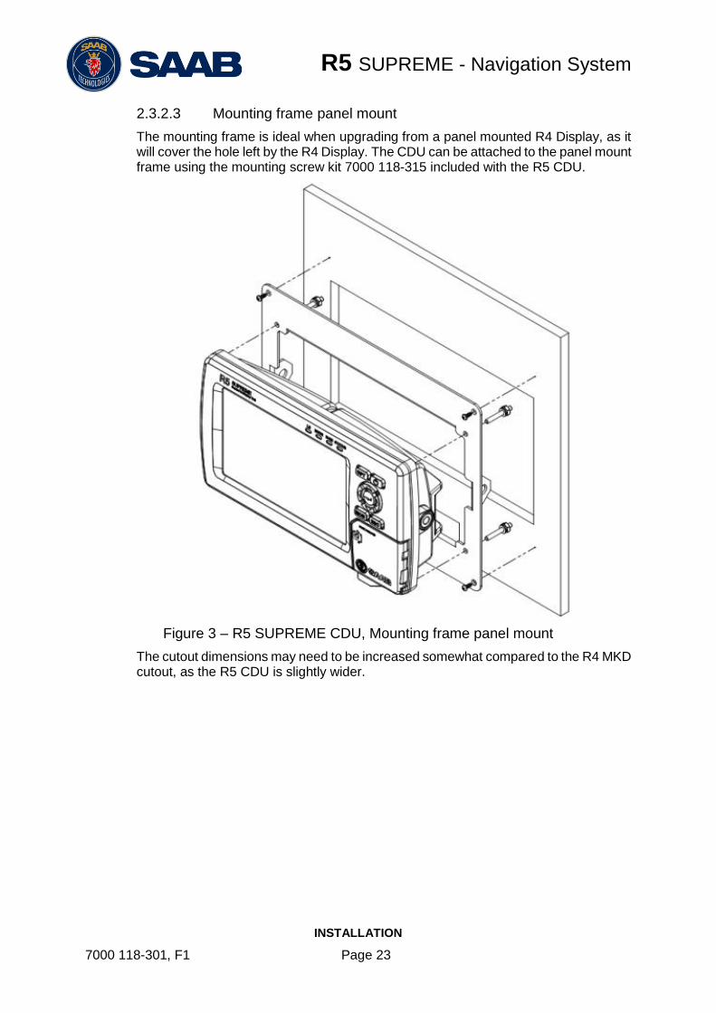
2.3.2.3 Mounting frame panel mount
The mounting frame is ideal when upgrading from a panel mounted R4 Display, as it will cover the hole left by the R4 Display. The CDU can be attached to the panel mount frame using the mounting screw kit 7000 118-315 included with the R5 CDU.
Figure 3 – R5 SUPREME CDU, Mounting frame panel mount
The cutout dimensions may need to be increased somewhat compared to the R4 MKD cutout, as the R5 CDU is slightly wider.

R5 SUPREME - Navigation System
INSTALLATION
7000 118-301, F1 Page 24
2.3.3 R5 CDU clearance area
Leave a clearance around the R5 NAV Junction Box to facilitate service and installation. See below figure for minimum recommended clearance area (measurements in mm).
Figure 4 – CDU Gimbal mount clearance
Figure 5 CDU Panel mount clearance

R5 SUPREME - Navigation System
INSTALLATION
7000 118-301, F1 Page 25
2.4 Mount the R4 Navigation Sensor
2.4.1 Sensor Location
When mounting the R4 Navigation Sensor, please consider the following:
Mount the unit so that the LEDs can be observed if needed for troubleshooting purposes.
The temperature and humidity should be moderate and stable, +15ºC to +35ºC. (Operating temperature: -30ºC to +70ºC.)
Select a location away from excessive heat sources.
Avoid areas where there is a high flow of humid salt air.
Avoid places with high levels of vibrations and shocks.
Ensure that there is enough airflow to avoid high ambient temperatures.
Ensure that the different cables can be connected without violating their maximum bending radius.
The unit can affect magnetic compasses. The minimum compass safe distance is 0.6 meters to a standard magnetic compass and 0.4 meters to a steering magnetic compass.
2.4.2 Sensor Clearance Area
Leave a clearance around the R4 Navigation Sensor to facilitate service and installation. See recommended clearance area in figure below.
Figure 6 – Clearance Area for R4 Navigation Sensor

R5 SUPREME - Navigation System
INSTALLATION
7000 118-301, F1 Page 26
2.5 Mount the GNSS or DGNSS Navigation Antenna
The R4 Navigation Sensor should be connected to the included antenna, which in the GPS/GNSS configuration is a MGA-3 GNSS antenna and in the DGPS/DGNSS configuration is a MGL-5 combined GNSS/Beacon antenna.
Attention should be paid to the location and installation of the different antennas on the ship in order to obtain the best possible signal reception. Installation of the Navigation Sensor’s antenna is a crucial part of the system installation. How and where you install your antenna and cable will greatly affect its sensing efficiency.
2.5.1 Antenna Location
Mount the MGA-3 or MGL-5 antenna at a location with a clear, unobstructed view of the sky. For best beacon reception performance, mount the MGL-5 antenna so that the center of the black gasket is at least 8 cm (3 in) above any metal surface.
Local noise generated by your vessel or surroundings may affect your navigation system performance. To minimize this impact, you should locate the antenna outside the path of any radar beam, away from any transmitting antennas, and away from any other sources of interference such as motors, solenoids and other electronics. Do not, however, mount the antenna in the top of a mast or tower, as this may degrade the COG and SOG readings.
The MGA-3 and MGL-5 uses a 1-14-UNS thread for mounting. Mount the antenna on a standard US 1” 14 thread pipe or other standard antenna mount (not included).
Note: Antennas threaded onto a mount should be tightened only by hand. Do not tighten the antenna by turning on the antenna cover, instead hold the mounting shaft located at the bottom of the antenna and tighten by hand. Do not thread the pipe deeper than ¾ into the antenna. Do not use tools to install the antenna on the pipe as this may cause damage. Damage caused by over tightening is not covered by warranty.
Note: Once the system has been correctly mounted and connected, it is possible to monitor the R4 Navigation Sensor receiving performance via the graphical interface of the R5 SUPREME CDU. This information can be used to locate the optimum placement of the antenna. This is further described in section 5.11.3.
2.5.2 Cabling
The maximum allowable cable loss is 18 dB for the MGA-3 and MGL-5 antennas. The maximum cable length depends on the attenuation of the cable and the chosen antenna.
Double shielded coaxial cable is recommended. The coaxial cable should be routed directly between the antenna and the R4 Navigation Sensor in order to reduce electromagnetic interference effects. The cable should not be installed close to high-power lines, such as radar or radio-transmitter lines or any AIS VHF antenna cable. A separation of one meter or more is recommended to avoid interference due to RF-coupling. Crossing of antenna cables should be done at 90 degrees to minimize magnetic field coupling.
The table below gives recommendation on cables that can be used for the GNSS-antenna connections. Due to the high frequency it’s important that the attenuation in the cable is low for the specific frequency (1.5 GHz).
Type Attenuation @ 1.5 GHz (dB/m)
(mm) Weight (kg/100m)

R5 SUPREME - Navigation System
INSTALLATION
7000 118-301, F1 Page 27
RG 58 0.9 5 3.7
RG 400 0.6 4.95 6.3
RG 223 0.6 5.40 5.5
RG 214 0.35 10.8 18.5
RG 225 0.3 10.9 23.3
Table 5 – GNSS Antenna Cables
For optimum performance of the R4 Navigation Sensor, 12 dB should remain after subtraction of cable loss from the antenna pre-amplifier gain. Thus, a maximum of 18 dB signal loss is allowed in the antenna cable, when using the 30 dB gain MGA-3 GNSS or MGL-5 Combined GNSS/Beacon antenna. Given this criteria, the following recommended cable maximum lengths have then been calculated.
Recommended maximum cable length using standard antenna
Cable Type Max length with MGA-3 or MGL-5
RG 58 20 m
RG 400 30 m
RG 223 30 m
RG 214 51 m
RG 225 60 m
Table 6 – Recommended Maximum GNSS Cable Length
Maximum cable length is calculated as:
Maximum cable length = allowed total loss / cable attenuation per meter
2.5.3 Cable Mounting
Coaxial cables should be installed in separate signal cable channels/tubes and at least 10 cm away from power supply cables. Crossing of cables should be done at right angles (90°).
Coaxial cables should not be exposed to sharp bends, which may lead to a change of the characteristic impedance of the cable. The minimum bending radius should be 5 times the cable's diameter.
All outdoor installed connectors should be weather proofed, e.g. with shrink tubing, watertight seal tape or butyl rubber tape and plastic tape sealing, to protect against water penetration into the antenna cable.
Secure the cable properly, near the cable ends.

R5 SUPREME - Navigation System
INSTALLATION
7000 118-301, F1 Page 28
2.5.4 Grounding
The MGA-3 and MGL-5 antennas do not require any antenna ground connection
2.6 Mount the R5 NAV Junction Box (if applicable)
For easy installation of the R5 SUPREME Navigation System, the R5 NAV Junction Box can be used to connect the R5 CDU to the R4 Navigation Sensor. The junction box also provides terminal connectors for external sensor equipment such as depth sensors and heading devices as well as connectors for alarm output, alarm acknowledgement and speed log output signals.
The R5 NAV Junction Box also has built in fuses for the R5 CDU and the R4 Navigation Sensor.
2.6.1 Junction Box Location
The R5 Signal Cables connecting the R5 CDU and the R4 Sensor to the Junction box are 2m long, hence this is the maximum distance between the Junction Box and the CDU or Sensor units.
The R5 NAV Junction Box is made from EMI shielded plastic.
2.6.2 Junction box clearance area
Leave a clearance around the R5 NAV Junction Box to facilitate service and installation. See below figure for minimum recommended clearance area (measurements in mm).

R5 SUPREME - Navigation System
INSTALLATION
7000 118-301, F1 Page 29
Figure 7 – Clearance Area for R5 AIS / NAV Junction boxes

R5 SUPREME - Navigation System
INSTALLATION
7000 118-301, F1 Page 30
2.6.3 Junction box Mounting
It is recommended to connect external cables to the Junction box before mounting the box to a surface.
Open the lid of the R5 NAV Junction Box.
Fix the box on an appropriate surface/place with using the screw holes on the four feet of the junction box.
Pull the cables through suitable cable glands. These glands are located on the front and back of the junction box. Please note that the glands can be removed if the cables are too thick. With the glands mounted, the maximum supported cable diameter is 12mm. Without the glands mounted, the maximum supported cable diameter is 19.5mm.
Shielded cables should be stripped down to the shielding and fastened with cable ties. There are eleven cable tie fastening points on the circuit board, one for every anti-vibration gland on the junction box. Make sure that the cable shielding touches the tin plated area at the fastening point. The maximum supported cable tie width is 4.5mm.
Grounding / Connect Ground screw to ship ground
Tighten the anti-vibration glands so that the cables are secured.
Connect the cables to the terminal blocks.
Fix the lid to the box casing.
2.6.1 Junction Box Interfaces
Please see Section 14 “Electrical Interfaces” for signal details.
The Junction box feature two 26-pin DSUB connectors, one male and one female.
All other connectors are internal of terminal block type.

R5 SUPREME - Navigation System
INSTALLATION
7000 118-301, F1 Page 31
2.6.2 System interconnection with R5 NAV Junction Box
User
Port 1
Speed
Log
Alarm
Relay
User
Port 4
User
Port 3
User
Port 2
Alarm
ACK
R4 GPS Navigation Sensor orR4 DGPS Navigation Sensor
(D)GPS Antenna
R5 NAV Junction Box
4
GP I/O
R5 NAV Sensor Cable
External power 24 VDC
R5 Signal Cable
R5 Power Cable
Figure 8 – Installation with R5 NAV Junction Box
1. Connect the R5 SUPREME CDU to the junction box by using the R5 Signal Cable, DSUB-DSUB and the R5 Power Cable, Connect the R4 Navigation Sensor to the junction box by using the R5 NAV Sensor Cable.
2. Connect the GNSS antenna to the R4 Navigation Sensor.
3. Connect Alarm Relay signal to bridge alarm.
4. Connect additional external sensors and equipment.
5. Connect the R5 NAV Junction Box to an external 24 VDC power source.
NOTE: see section 2.3 “Installation Cables” for cable specifications.

R5 SUPREME - Navigation System
INSTALLATION
7000 118-301, F1 Page 32
2.7 System interconnection without R5 NAV Junction box
System Port
User Port 1
User Port 2
Speed Log
Alarm Output
RS-422 Ports
User Port 3
User Port 4
R4 Sensor
Alarm ACK
Binary PortsRS-422 Ports
R4 Nav Signal and Power Cable
R4 GPS Navigation Sensor orR4 DGPS Navigation Sensor
(D)GPS Antenna
24 VDC/1A External fuse
24 VDC/2A External fuse
R5 Signal Cable DSUB-OPENR5 Power Cable
Figure 9 – Installation without R5 NAV Junction Box
2.7.1 R4 Sensor Power and Signal Cable
The R4 Sensor Power and Signal Cable, 7000 109-011 (ConXall to Open) is used when there is no R5 NAV Junction Box available.
Figure 9 describes the system interconnection used in this case. The Navigation sensor cable is connected by an 18-pin ConXall connector to the sensor and supplies several different interfaces as indicated by Figure 9. The cable is also used to apply power to the sensor.
Important:
The shield of the R4 Navigation Sensor power and signal cable (7000 109-011) is referenced to the negative DC supply.. For the same reason, don’t connect the Navigation Sensor alarm acknowledge signal ground, the speed log pulse signal ground or the cable shield for the GNSS antenna to the ship’s structure.
Note: The Chassis of the R4 Navigation Sensor is not connected to any internal ground and may thus be connected to the ship’s structure if desired.
2.7.2 R5 Signal Cable DSUB-Open
The R5 Signal Cable DSUB-Open is an open ended variant of the R5 Signal Cable DSUB-DSUB. When this cable is connected to the R5 CDU I/O Port it will provide signals as indicated in Figure 9.

R5 SUPREME - Navigation System
INSTALLATION
7000 118-301, F1 Page 33
2.7.3 Connect R5 CDU Sensor port to R4 Navigation Sensor
R5 Signal Cable DSUB-OPEN
R4 Navigation Sensor Signal and Power Cable
Brown (TX A)White (TX B)
Grey/Pink (RX B)Red/Blue (RX A)
Green (RX A)Yellow (RX B)
Purple (TX B)Black (TX A)
R5 CDU Sensor port R4 Sensor System Port
CDU
Pin
Signal Name R5 Signal Cable
DSUB-OPEN
R4 Navigation sensor
signal/power cable
Signal Name Sensor
Pin
1 Sensor Port TxB (+)
White Yellow System Port
RxB (+) 5
2 Sensor Port TxA (-)
Brown Green System Port
RxA (-) 2
11 Sensor Port RxB (+)
Grey / Pink Purple System Port
TxB (+) 11
12 Sensor Port RxA (-)
Red / Blue Black System Port
TxA (-) 10

R5 SUPREME - Navigation System
INSTALLATION
7000 118-301, F1 Page 34
2.8 Electrical Installation
2.8.1 Power Supply
The R5 SUPREME CDU and the R4 Navigation Sensor can be connected to an emergency power source. If connected to an emergency battery, a re-calculation must be made for the battery capacity. For power consumption, see chapter 8 “Technical Specifications”.
The R4 Navigation Sensor is designed to operate on 12-24 VDC. The nominal power used is 2.7 W. The R4 Navigation Sensor shall be externally fused (slow blow fuse) with a 1 A fuse.
The R5 SUPREME CDU is designed to operate on 12-24 VDC. The nominal power used is 13 W. The SUPREME CDU shall be externally fused (slow blow fuse) with a 5A fuse.
The R5 NAV Junction Box has built in fuses for both the R5 SUPREME CDU and the R4 Navigation Sensor.
2.8.2 Sensor Interface ports
Below signals can be accessed in the R5 NAV Junction box, or using the R4 Navigation Sensor Signal and Power Cable.
See Chapter 14 for electrical details.
2.8.2.1 System Port
The System port interface is used to connect to the R5 SUPREME CDU, via the Sensor port on the R5 SUPREME CDU. The TX signal of the System port shall be connected to the RX signals of Sensor port on the CDU, and the RX signals of the System port shall be connected to the TX signals of the R5 SUPREME CDU Sensor port.
2.8.2.2 User Port 1
The port is bidirectional and can be used to connect to external equipment such as an ECDIS system, or to external sensors such as compass or depth sensors. It is recommended to use this port when connecting to ECDIS systems.
To receive data on the port, its RX signals shall be connected to the TX signals of the external equipment.
For an external equipment to receive data from the R5 SUPREME Navigation System via the port, the TX signals of the port shall be connected to the RX signals of the external equipment.
It is up to the user to configure the types of messages that shall be sent and received on the port, as well as the baud rate used for communication.
This port may also be configured for input of external differential corrections in RTCM SC-104 format. In this case, the port cannot be used for output of data. Refer to the parameter “Correction Source” described in section 4.2.2 on how to configure the port for differential corrections.

R5 SUPREME - Navigation System
INSTALLATION
7000 118-301, F1 Page 35
2.8.2.3 User Port 2
The port can only be used to output data from the R5 SUPREME Navigation System to external equipment. The TX signals of the port shall be connected to the RX signals of the external equipment.
It is up to the user to configure the types of messages that shall be sent on the port, as well as the baud rate used for communication.
If an R4 DGPS/DGNSS Navigational Sensor is used this port can also be used to output differential corrections in RTCM SC-104 format.
2.8.2.4 Alarm Out Binary Port
The Alarm Out binary port is used to indicate navigational alarms to external alarm signalling and alarm monitoring systems. The Alarm Out wire should be connected via an alarm relay unit to negative supply. The port is normally active supplying power. When an alarm is activated, the port will go low and supply 0 VDC. The port will remain low until the alarm is deactivated. Once the alarm is deactivated the port will go high, supplying power again.
If the R5 NAV Junction box is installed, this signal will be connected to the Junction box internal alarm relay.
2.8.2.5 Alarm Acknowledge Binary Port
The Alarm Acknowledge binary port is used to acknowledge all active alarms. The Alarm Ack In signal should be connected to Alarm Ack GND via a normally open momentary switch. The switch should be closed to activate the Alarm Acknowledge signal and acknowledge the active alarms.
2.8.2.6 Speed Log Out Port
To use the port, the Speed Log Out signal should be connected via a pulse counting circuit to Signal ground.
The number of pulses that can be generated per nautical mile can range between 100 and 400, configured as described in the section 4.2.12 “Port Rates”. The default setting is that Speed Log output is disabled.

R5 SUPREME - Navigation System
INSTALLATION
7000 118-301, F1 Page 36
2.8.3 R5 CDU Interface ports
Below signals can be accessed in the R5 NAV Junction box, or using the R5 Signal Cable DSUB-OPEN.
See Chapter 14 for electrical details.
2.8.3.1 Sensor Port
The Sensor port is used to connect to the R4 Navigation Sensor unit. The Tx signals of the port shall be connected to the Rx signals of the System port on the R4 Navigation Sensor. The Rx signals of the Sensor port should be connected to the Tx signals of the System port on the R4 Navigation Sensor.
2.8.3.2 User Port 3 and User Port 4
Theses ports are bidirectional and can be used to connect to external equipment and sensors, such as a compass or depth sensor.
To receive data on the ports, their RX signals shall be connected to the TX signals of the external equipment.
For an external equipment to receive data from the R5 SUPREME Navigation System via the ports, the TX signals of the ports shall be connected to the RX signals of the external equipment.
It is up to the user to configure the types of messages that shall be sent and received on the ports, as well as the baud rates used for communication.
User Port 3 and User Port 4 on the R5 SUPREME CDU are high-speed ports with isolated power and ground. They can be used to interface equipment in a “high-speed craft” installation for output of NMEA GPS sentences. All user port baud rates and sentence outputs can be configured via the R5 SUPREME CDU.
R5 SUPREME - Navigation System
CONCEPTS AND TERMINOLOGY
7000 118-301, F1 Page 37
3 CONCEPTS AND TERMINOLOGY
This chapter describes some of the commonly used terms of this manual, and the implied meaning when used in this manual.
Waypoint
A waypoint is a position on the earth's surface, represented by latitude and longitude, which is given a unique name. A waypoint is typically used for navigation direct to a certain position or as part of a route.
MOB Waypoint
A temporary waypoint created when using the Man Over Board (MOB) functionality. It is not possible to use MOB waypoints in routes.
Route
A route is a named, ordered sequence of waypoints, which together describes a path from the start to the end waypoint. The route currently being sailed is called the active route.
Active Route
The active route is the route currently being sailed and used for navigation. When starting to sail a route, a copy of the route is made into the active route. Changes made to the active route do not affect the source route, unless the active route is explicitly stored. Only one route can be active at any one point in time.
Leg
A leg is the segment of a route between two consecutive waypoints. A route with the waypoints A, B and C has two legs: “A to B” and “B to C”. For each leg in a route, the navigation algorithm, RAIM accuracy level and cross track error (XTE) limit can be set.
RAIM
RAIM stands for “Receiver Autonomous Integrity Monitoring” and is a navigation solution integrity monitoring scheme that evaluates the quality of the position data and is able (under normal circumstances) to detect a satellite malfunction that results in a large range error. The user can specify a RAIM accuracy level and the system will give a warning if the range error is larger than this specified accuracy level.
RAIM Accuracy Level
The RAIM accuracy level is the radius that is used to calculate current RAIM status.
RAIM Status
The RAIM status can be one of safe, caution and unsafe, and is indicated by the RAIM LED on the front of the R5 SUPREME CDU. If the calculated range error is larger than the currently used RAIM accuracy level, the RAIM status will be “unsafe” and indicated with a red light on the RAIM LED. If the error is smaller than the accuracy level, the RAIM status will be “safe” and indicated with a green light on the RAIM LED. If not enough satellites are received to be able to perform the RAIM calculation, the RAIM status will be “caution” and indicated with yellow light on the RAIM LED.
Navigation Algorithm

R5 SUPREME - Navigation System
CONCEPTS AND TERMINOLOGY
7000 118-301, F1 Page 38
The navigation algorithm is the algorithm used for calculating the course to steer to reach the next waypoint. It is also used for calculating the distance to the waypoint. The navigation algorithm can be either great circle or rhumb line.
Great Circle Navigation
The great circle navigation algorithm calculates a course line that is the shortest path between two points on the surface of the earth. The course to steer when navigating towards a waypoint is not constant using this navigation algorithm. The resulting track of this navigation algorithm will differ from the straight line drawn on a Mercator projected chart.
Rhumb Line Navigation
The rhumb line navigation algorithm calculates a course line that corresponds to a straight line on a Mercator projected chart, and cuts across all meridians at the same angle.
Waypoint Pass Criterion
The criterion used to determine when a waypoint in the active route is considered passed. The waypoint pass criterion can be any of Manual, Distance, Bisector Line and Perpendicular Line.
Manual Waypoint Pass Criterion
Using this pass criterion, the waypoint is only considered passed when the operator skips the waypoint.
Distance Waypoint Pass Criterion
Using this pass criterion, the waypoint is considered passed once the ship has reached an imaginary circle around the waypoint. See illustration to the right. The radius of the circle is configurable.
Bisector Line Waypoint Pass Criterion
Using this pass criterion, the waypoint is considered passed once the ship has reached an imaginary bisector line of the angle between current and next leg. See illustration to the right.
Perpendicular Line Waypoint Pass Criterion
Using this pass criterion, the waypoint is considered passed once the ship has reached an imaginary line perpendicular to current leg. See illustration to the right.

R5 SUPREME - Navigation System
CONFIGURATION
7000 118-301, F1 Page 39
4 CONFIGURATION
When the physical and electrical installation of the system is complete, the R5 SUPREME Navigation System needs to be configured. This chapter describes what the installer is required to do before the R5 SUPREME Navigation System is fully functional.
4.1 Configuration Wizard
The first time the R5 SUPREME CDU is started, a configuration wizard will be shown. This wizard is a helpful guide to configure the basic functionality of the R5 SUPREME System. The following sections describe the different steps in the configuration wizard.
4.1.1 Calibration View
Figure 10 – Calibration View
The first time the R5 SUPREME CDU is used, the touch screen needs to be calibrated. A crosshair will be shown on the screen at five different locations. Press on the crosshair each time it appears to calibrate the touch screen. Try to hit the centre of the cross as accurate as possible for the best possible calibration. When the calibration is done, a test screen will appear where the new touch settings can be tested. Press anywhere on the screen to move the crosshair. Accept the new calibration by pressing ENTER on the keypad or press ESC to re-calibrate.

R5 SUPREME - Navigation System
CONFIGURATION
7000 118-301, F1 Page 40
4.1.2 System Setup
Figure 11 – System Setup
The R5 SUPREME CDU can be used in a standalone AIS system, standalone Navigation system, Combined AIS and Navigation system or be used as a slave display to an existing R5 Navigation System. The Navigation system can also be in two different configurations with either an R4 GPS/GNSS sensor or an R4 DGPS/DGNSS sensor. It is up to the user to specify which equipment is connected to the R5 SUPREME CDU.
4.1.3 Network Configuration
Figure 12 – Network Configuration
The R5 SUPREME CDU uses Light Weight Ethernet (LWE) to communicate with the R5 SUPREME Transponder as well as other R5 SUPREME CDU units in multi display or redundant configurations. It is therefore necessary to configure an IP number and a Light Weight Ethernet network ID for the R5 SUPREME CDU. The LWE ID consists of two letters (always “GP” for the R5 SUPREME CDU) and four digits. The LWE ID must be unique for all equipment connected to the LWE network.
4.1.4 Select CDU Master (Slave Mode Only)
If the R5 SUPREME CDU is configured to be used as a slave display to an existing R5 SUPREME Navigation system, the master CDU must be selected on the LWE network in order to receive GNSS data and synchronize waypoints, routes and configurations.
Make sure that the master R5 SUPREME Navigation System is powered on and is connected to the LWE network. On the slave display, press the button “Refresh List” in

R5 SUPREME - Navigation System
CONFIGURATION
7000 118-301, F1 Page 41
the Select CDU Master view to search for R5 SUPREME CDU units on the LWE network. Select the R5 SUPREME CDU that shall provide GNSS data to the slave unit and press “Next”.
Note: The master R5 SUPREME CDU must also be configured to provide GNSS data on the LWE network and the slave unit must be selected in the master R5 SUPREME CDU’s Redundant Nav view in order to synchronize the databases between slave and master unit. For a more detailed description how to connect and configure multi display and redundant systems, see chapter 6.
Figure 13 – Select CDU Master
4.1.5 Connection View
This view is shown while the R5 SUPREME CDU connects to external equipment and initializes the system. When the initialization is complete the R5 SUPREME CDU will automatically switch to the Position view when configured as a Navigation System.
Figure 14 – Connection View
4.2 Configuration Parameters
The following sections lists and describes all the parameters that can be configured in the R5 SUPREME Navigation System. All the configuration sub menus can be found under Main Menu Maintenance Configuration.

R5 SUPREME - Navigation System
CONFIGURATION
7000 118-301, F1 Page 42
4.2.1 Navigation
The Navigation Configuration view is accessed by pressing Main Menu Maintenance Configuration Navigation
Parameter Name Description
Waypoint Pass Criteria The criteria that should be used to determine if a waypoint has been passed or not. Refer to chapter 3 for more information.
Waypoint Pass Distance If the Waypoint Pass Criteria is set to “Distance”, this parameter specifies the distance that should be used to determine if the waypoint has been passed or not. Refer to chapter 3 for more information.
Start Sail From This parameter determines how the system should behave when starting to sail a new active route.
If set to “No Waypoint (t0)”, the system will navigate to the first waypoint in the active route without calculating a cross-track error. It will also output current position as ‘from’ waypoint with identifier ‘t0’ in active route RTE message.
If set to “Start Position (t1)”, the system will create a waypoint with identifier ‘t1’ at current position when starting to sail the new route and thus create a leg between ‘t1’ and the first actual waypoint in the route. Cross-track error will be calculated while sailing towards the first waypoint and ‘t1’ will be output as ‘from’ waypoint in route RTE message. The newly created ‘t1’ waypoint will be visible in the active route but it will not be added to the waypoint database.
Default RAIM Level This is the default RAIM level that will be used by the system if no specific RAIM level is set on the current leg of the active route. The currently used RAIM level is always shown in the upper right corner of the R5 SUPREME CDU. For more information about RAIM, refer to chapter 3.
All legs of a newly created route as well as incoming routes on serial interface will use the default RAIM level unless specifically changed in the route.
Navigation Algorithm This is the default navigation algorithm that will be used for bearing and range calculation by the system if no other navigation algorithm is set on the on the current leg of the active route.
All legs of a newly created route as well as incoming routes on serial interface will use the

R5 SUPREME - Navigation System
CONFIGURATION
7000 118-301, F1 Page 43
default navigation algorithm unless specifically changed in the route.
Refer to chapter 3 for more information about the navigation algorithms.
Cross Track Error Limit This parameter determines the default cross track error (XTE) limit that is used by the system if no other XTE limit is set on the current leg of the active route.
All legs of a newly created route as well as incoming routes on serial interface will use this default XTE limit unless specifically changed in the route.
If the distance between the own ship and the current active leg exceeds the currently used XTE limit, the “XTE Limit Exceeded” alarm will become active. The alarm remains active until the cross track error becomes less than the set XTE Limit, or navigation along the active route stops.
Approach Distance The Approach Distance parameter specifies at which distance to next waypoint the Waypoint Approaching (Distance) alarm is raised.
Approach Time The Approach Time parameter specifies the estimated time (in minutes) before arrival to the next waypoint when the Waypoint Approaching (Time) alarm is raised.
The time is estimated by dividing the calculated distance to the waypoint with the average SOG value (calculated over the time specified by the “Average SOG Time” parameter). The estimated time is accurate if the course is directly towards to the waypoint.
Average SOG Time The Average SOG Time parameter defines the time period over which average speed is calculated when estimating time of arrival (ETA) to the end of the active route and Time To Go (TTG) to the next waypoint.
RTE/Rnn WP Limit Determines the maximum number of remaining waypoints in the active route that shall be transmitted in RTE and Rnn messages.
Status Information The Status Information parameter defines whether current position (when available) from the R4 Navigation Sensor or the name of the next waypoint is to be displayed in the status bar at the upper left corner of the R5 SUPREME CDU.
Local Time Zone Offset Output in ZDA
The Output in ZDA parameter defines if the local time zone offset set in the Time Config view should be output in ZDA messages. When the parameter is set

R5 SUPREME - Navigation System
CONFIGURATION
7000 118-301, F1 Page 44
to Disabled the local time zone offset fields in ZDA messages will be null fields. When set to Enabled the local time zone offset fields in ZDA messages will be defined by the settings in Time Config view. If UTC time is used the fields will be zeros in ZDA messages.
4.2.2 GPS
This view is accessed by pressing Main Menu Configuration GPS / DGPS GPS
Parameter Name Description
Elevation Mask This parameter sets the elevation cutoff mask angle, in degrees, for satellites.. Any satellites below this mask angle will be ignored, even if available. The value should be between 0° and 60°, and the default value is 5°.
Correction Age This parameter sets the maximum allowed age (in seconds) for correction data. The R4 Navigation Sensor is able to use old correction data for extended periods of time. The default setting is 120 seconds. The lowest allowed value is 10 seconds and the highest 900 seconds. When increasing the allowed correction age, ensure that the new setting meets your requirements as accuracy will degrade with increasing correction age.
Correction Source This parameter sets the source for differential corrections. Valid settings are:
Beacon. In this setting the system will use signals from IALA radio beacon stations as source for differential corrections. This setting is only available when using an R4 DGPS or DGNSS Navigation Sensor.
SBAS. This setting makes the system use SBAS satellite signals as source for differential corrections.
User Port 1. This setting will command the system to apply external differential corrections received in RTCM SC-104 format on the User 1 port. The User 1 port will not be available for output of serial data from the system if this setting is selected.
None. This setting makes the system operate in autonomous mode, not using any differential corrections.
SOG Smoothing The SOG Smoothing parameter allows you to adjust the level of responsiveness of the speed over ground (SOG) measurement, as displayed by the R5

R5 SUPREME - Navigation System
CONFIGURATION
7000 118-301, F1 Page 45
SUPREME CDU and provided in the $GPVTG and $GPRMC sentences. The default value is zero, and increasing the value will increase the level of SOG smoothing.
The setting of this parameter depends upon the expected dynamics of the vessel. If a ship is highly dynamic, this value should be set to a lower value since the filtering window needs be shorter in time, resulting in a more responsive measurement. However, if a vessel is very large and has much more resistance to change in its motion, this value can be increased to reduce measurement noise. The following formula provides some guidance on how to set this value:
SOG smoothing = 10 / maximum acceleration (in m/s²).
If unsure on which value to set, it's best to be conservative and leave this parameter at the default setting of 0.00 seconds.
COG Smoothing The COG Smoothing parameter allows you to adjust the level of responsiveness of the course over ground (COG) measurement, as displayed by the R5 SUPREME CDU and provided in the $GPVTG and $GPRMC sentences. The default value is zero, and increasing the value will increase the level of COG smoothing.
As with the SOG smoothing parameter, the setting of this parameter depends upon the expected dynamics of the vessel. If a ship is highly dynamic, this value should be set to a lower value since the filtering window needs be shorter in time, resulting in a more responsive measurement. However, if a vessel is very large and has much more resistance to change in its motion, this value can be increased to reduce measurement noise. The following formula provides some guidance on how to set this value initially. It is however recommended that you test how the revised value works in practice.
COG smoothing = 10 / maximum rate of change in course (in °/s).
Note: The ship needs to be moving to calculate a valid COG value. Do not use COG values output while the ship is at rest as a basis for adjusting this parameter.
If unsure on which value to set, it's best to be conservative and leave this parameter at the default setting of 0.00 seconds.
GLONASS Support This is only available with the R4 GNSS and DGNSS sensors. Enabling GLONASS support will allow the

R5 SUPREME - Navigation System
CONFIGURATION
7000 118-301, F1 Page 46
sensor to include GLONASS satellites in the navigation solution. It is recommended to keep enabled. The multi GNSS mode can improve reliability in areas with poor GPS reception, and also make the sensor less sensitive to interference.
Position Accuracy (Decimal Places)
This parameter controls the number of decimals used in to present latitude and longitude in position sentences.
4.2.3 SBAS
This view is accessed by pressing Main Menu Maintenance Configuration GPS/DGPS SBAS
Parameter Name Description
PRN Search Mode Change between Automatic or Manual search mode.
In Manual search mode, the R4 Navigation sensor will try to acquire signals from satellites with id (PRN) numbers input by the parameters PRN 1 and PRN 2 in the view. If only one particular satellite is to be tracked, input same number for both parameters.
In Automatic search mode, the R4 Navigation Sensor will try to identify and track SBAS signals without user control of satellite selection.
PRN 1 (Primary) The PRN of the primary satellite that should be used when operating in Manual PRN Search Mode.
PRN 2 (Secondary) The PRN of the secondary satellite that should be used when operating in Manual PRN Search Mode.
PRN 3 The PRN of the third satellite that should be used when operating in Manual PRN Search Mode.
4.2.4 Beacon
This view is only available when using a R4 DGPS/DGNSS Navigation Sensor. It is accessed by pressing Main Menu Maintenance Configuration GPS/DGPS Beacon
Parameter Name Description
Tuning Mode The Tuning Mode parameter sets the frequency selection mode of the R4 DGPS/DGNSS Navigation Sensor internal radio beacon receiver. The mode can be Frequency Scan, Manual or Database (Auto).
In Frequency Scan mode, the beacon receiver will search available frequencies and tune to the strongest

R5 SUPREME - Navigation System
CONFIGURATION
7000 118-301, F1 Page 47
beacon signal. In this mode, the Navigation Sensor continuously performs background search to discover higher quality differential signals. While performing background searches, the navigation Sensor continues to receive differential corrections from the current radio beacon station.
In Manual tuning mode, the Navigation Sensor tunes to the specified beacon frequency for receiving DGNSS signals.
In Database mode, the receiver will search for the closest station based on its current location and distance to the internal list of station locations. The frequency and bit rate specified in the station database will be used and therefore these parameters are hidden when the Tuning Mode parameter is set to Database (Auto).
Frequency (kHz) The Frequency parameter is used to set the frequency to use for receiving DGNSS Beacon signals, when the frequency mode parameter is set to manual. Valid frequencies are between 283.5 and 325 KHz, at 0.5 kHz intervals. This parameter is only available when Tuning Mode is set to manual.
Bit Rate Mode The Bit Rate Mode parameter sets the bit rate mode to either Automatic or Manual. In Automatic mode the R4 DGNSS Navigation Sensor will automatically select the correct bit rate to use for demodulating the radio beacon signal. In Manual mode, the R4 DGNSS Navigation Sensor will use the specified bit rate.
This parameter is automatically set to Auto when Tuning Mode is set to Database (Auto) since the bit rate specified in the database will automatically be used.
Bit Rate (bps) The Bit Rate parameter is used to set the bit rate used for demodulation of the DGNSS Beacon signal when using the manual bit rate mode. The bit rate can be set to one of 50, 100 or 200 bps. This parameter is only available when Bit Rate Mode is set to manual.
4.2.5 GNSS antenna Offset
The GNSS antenna offset feature can adjust the system position in Latitude and Longitude using a preselected offset and external heading input.
This allows the GNSS antenna to be located anywhere on a vessel, and still have the position from a different reference point on the vessel.
This is feature is useful to prevent big shifts in position when a backup GNSS system takes over from a primary GNSS system, and the two systems have a large GNSS antenna separation.

R5 SUPREME - Navigation System
CONFIGURATION
7000 118-301, F1 Page 48
During system setup of output port rates, it is important to set output of position sentences with offset in order to let external systems receive offset data. See section 10.2 “Output Sentences”.
NOTE: True heading data is required to calculate position offset. GNSS antenna offset will be zero if there is no valid heading data.
Figure 15 – Antenna Offset
This view is accessed by pressing Main Menu Maintenance Configuration GPS/DGPS GPS Antenna Offset
Parameter Name Description
Forward Offset The Forward Offset parameter is used to set the forward/backward distance from the GNSS antenna to the desired reference position. Enter a negative value to set a backward offset.
Starboard Offset The Starboard Offset parameter is used to set the port/starboard distance from the GNSS antenna to the desired reference position. Enter a negative value to set a port offset.
GPS Antenna Offset This parameter is used to enable/disable the GNSS antenna offset function.
4.2.6 Visual Settings
Press the OPT button for 5 seconds to reset the visual settings to the default values.
To quickly turn off all backlight on the R5 SUPREME CDU, press once on the PWR button on the front of the CDU. This will completely turn off all backlight for the LCD; LED’s and buttons on the R5 SUPREME CDU. However, if there is an active, unacknowledged alarm in the system, the STATUS LED will still be visible and blink with a red light. To return to previous light settings, press the PWR button again.

R5 SUPREME - Navigation System
CONFIGURATION
7000 118-301, F1 Page 49
It is also possible to quickly change the overall brightness level by changing the “Master Level” parameter value. This can be done from the Visual Settings view or by holding down the PWR button for 2 seconds. This will enable the PWR button options menu, press “Dim Backlight” to set the percentage value for the backlight of the LCD, LED’s and buttons. The “Dim Backlight” button is only available when the dimming mode is set to “Manual” in the Visual Settings view.
Figure 16 – Power Down Menu
To switch between automatic or manual dimming mode and to fine tune backlight for buttons, LCD and LEDs, enter the Visual Settings view which is accessed from Main Menu Maintenance Configuration Display Visual Settings
Parameter Name Description
Dimming Mode If set to “Manual”, the LCD backlight, button illumination and LED intensity are controlled by the user with the parameters described below.
If set to “Automatic”, the LCD backlight, button illumination and LED intensity will automatically be controlled with the light sensor on the front of the R5 SUPREME CDU. The less ambient light registered by the light sensor, the lower percentage of backlight and brightness will be used.
NOTE: The light sensor may be too directional in some environments. Use manual mode if unsatisfactory performance of automatic mode.
Default: Manual
Master Level The master level controls the overall brightness level in percent of the selected maximum level for LCD backlight, LED intensity and button illumination.
This parameter is only available when the “Dimming Mode” parameter is set to “Manual”.
This parameter can also be changed by holding down the PWR button on the front of the R5 SUPREME CDU and then press the button “Dim Backlight”.
Default: 80%
LCD Backlight Controls the maximum LCD backlight level %.

R5 SUPREME - Navigation System
CONFIGURATION
7000 118-301, F1 Page 50
Default: 80%
LED Intensity Controls the maximum LED intensity level %.
Default: 80%
Button Illumination Controls the maximum button illumination level in percent.
Default: 80%

R5 SUPREME - Navigation System
CONFIGURATION
7000 118-301, F1 Page 51
4.2.7 Sound
This view is accessed by pressing Main Menu Maintenance Configuration Display Sound
Parameter Name Description
Alarm Volume Determines the volume of the R5 SUPREME CDU internal speaker.
Alarm Waiting For ACK Determines how the R5 SUPREME CDU speaker should behave when an alarm is active and waiting for acknowledgement. This setting does NOT affect the behavior of the alarm binary output signal or any external alarm system.
DGPS Message Controls the behavior of the R5 SUPREME CDU speaker when a new DGPS (RTCM, Type16) message has been received.
Man Over Board Controls the behavior of the R5 SUPREME CDU speaker when a MOB waypoint has been activated.
4.2.8 Time
This view is accessed by pressing Main Maintenance Configuration Display Time
Parameter Name Description
Time Zone This parameter defines if the times that are displayed in the R5 SUPREME CDU should be in UTC or LOC (local) time. If local time is chosen, the offset from UTC must be specified with the three parameters listed below.
Offset sign The sign of the local time offset from UTC.
Hours The local time hour offset from UTC.
Minutes The local time minute offset from UTC.
4.2.9 Units
This view is accessed by pressing Main Maintenance Configuration Display Units
Parameter Name Description

R5 SUPREME - Navigation System
CONFIGURATION
7000 118-301, F1 Page 52
Range Unit This parameter determines the unit of the range values displayed in R5 SUPREME CDU like e.g. the range to the next waypoint. Range values can be calculated in nautical miles (NM), kilometers (km) or statute miles (Sm).
Speed Unit This parameter determines the unit for the SOG values displayed in the R5 SUPREME CDU. The SOG value can be calculated in knots (kn), kilometers per hour (km/h) or miles per hour (mph).
Depth Unit This parameter determines the unit for the depth values displayed in the R5 SUPREME CDU. The depth value can be calculated in meters (m), feet (ft) or fathoms (ftm).
Anchor Range Unit This parameter determines the unit of the range value to the reference position displayed in the Anchor Watch view in the R5 SUPREME CDU. It can be calculated in meters (m) or feet (ft).
4.2.10 CDU Password
This view is accessed by pressing Main Maintenance Configuration Display CDU Password
Parameter Name Description
New CDU Password Changes the password for the R5 SUPREME CDU.
The default CDU password is “cdupwd”
Restore Password Key It is possible to restore the CDU password to the default value above with a secret restore key.
To obtain the restore key, contact TransponderTech Support and be prepared to provide the serial number of the R5 SUPREME CDU unit.
4.2.11 Alarm
This view is accessed by pressing Main Menu Maintenance Configuration Alarms
In this view all alarms can be configured to either “Enabled” or “Disabled”. When the alarm is enabled, an active alarm will trigger the external alarm discrete output signal, activate the internal speaker in the R5 SUPREME CDU and a popup dialog will appear.
There are also two parameters that decide how the acknowledge alarm function should affect the system.
Parameter Name Description

R5 SUPREME - Navigation System
CONFIGURATION
7000 118-301, F1 Page 53
Allow External ACK If set to “Enabled” all alarms will be acknowledged if the binary alarm ACK signal is triggered.
If set to “Disabled”, the binary alarm ACK signal will be ignored.
See section 14.2.4.2 “Alarm Acknowledge Binary Port” for more information about external ACK signal.
ACK Disables Discrete Output If set to ‘Yes’, the alarm discrete output signal will be reset as soon as all active alarms have been acknowledged.
If set to ‘No’, the alarm discrete output signal will be active as soon as there are any active alarms, regardless of acknowledgement state.
See section 14.2.4.3 “Alarm Out Binary Port” for more information about the alarm discrete output signal.
4.2.12 Port Rates
This view is accessed by pressing Main Maintenance Configuration Interface Port Rates
In this view it is possible to configure the baud rate for the four different User ports in the R5 Navigation System, as well as the pulse rate of the Speed Log output.
User Port 1 has a maximum baud rate of 38400 bps.
User Port 2 has a maximum baud rate of 19200 bps
User Port 3 and 4 can be configured up to 115200 bps.
The higher the baud rate, the more sentences can be output on the specific port. In the Output Config views (see section 4.2.17) an estimated port load is calculated depending on the selected baud rate and the configured output sentences.
The Speed Log output can be set to:
Disabled (default)
100 Pulses/NM
200 Pulses/NM
300 Pulses/NM
400 Pulses/NM
4.2.13 Own CDU Settings (Network)
This view is accessed by pressing Main Menu Configuration Interface Network Own CDU Settings
Parameter Name Description
CDU IP Address The Internet Protocol (IP) address of the R5 SUPREME CDU.

R5 SUPREME - Navigation System
CONFIGURATION
7000 118-301, F1 Page 54
CDU LWE ID The unique ID that is used on the Light Weight Ethernet network. For example if this parameter is set to “3141” the R5 SUPREME CDU will transmit messages on the LWE network with the LWE ID “GP3141”.
This ID must be unique for all equipment connected to the same LWE network.
4.2.14 Compass Data Port
This view is accessed by pressing Main Maintenance Configuration Interface Input Compass Data Port
Parameter Name Description
Input Port Specifies the input port that should be used for heading sensor data. Can be set to User Port 1, 3 or 4 or to “Any”.
Heading sensor data received on a port that does not correspond to this setting will be ignored.
Input Sentence This parameter makes it possible to only use a specific NMEA sentence for heading data.
Input Talker ID This parameter makes it possible to only use sentences from a specific talker (having a specific NMEA talker ID) for the heading data.
4.2.15 Depth Data Port
This view is accessed by pressing Main Maintenance Configuration Interface Input Depth Data Port
Parameter Name Description
Input Port Specifies the input port that should be used for depth sensor data. Can be set to User Port 1, 3 or 4 or to “Any”.
Depth sensor data received on a port that does not correspond to this setting will be ignored.
Input Sentence This parameter makes it possible to only use a specific NMEA sentence for depth data.
Input Talker ID This parameter makes it possible to only use sentences from a specific talker (having a specific NMEA talker ID) for the depth data.

R5 SUPREME - Navigation System
CONFIGURATION
7000 118-301, F1 Page 55
Use NMEA Offset If yes, any depth offset information available in the DPT sentence is added to the depth value taken from this sentence.
Use Manual Offset If yes, the manually specified offset is added to the reported depth (regardless from which sentence it is taken).
Manual Offset Specifies the size of the manual offset for depth.
Manual Offset Sign Specifies the sign of the manual offset. If positive, the manual offset is added to the reported depth. If negative, the manual offset is subtracted from the reported depth.
4.2.16 WPT/RTE Data Port
This view is accessed by pressing Main Maintenance Configuration Interface Input Depth Data Port
Parameter Name Description
Input Port Specifies the input port that should be used for input of waypoints and routes. Can be set to User Port 1, 3 or 4 or to “Any”.
Waypoints and routes received on a port that does not correspond to this setting will be ignored.
Input Sentence This parameter makes it possible to only use a specific NMEA sentence for routes.
Input of routes with Rnn-sentence will always be considered as a “working” route i.e. it will replace the current active route in the system.
Input of routes with RTE-sentence can either mean working route or complete route depending on information in the RTE-sentence. A working route will replace the currently active route. A complete route will be added to the route database. If a route with the same name already exists in the database, the existing route will be overwritten with the new route.
All legs of the route will use the default settings of Nav-Algorithm, RAIM level and XTE Limit as configured in the Navigation Config View (see section 4.2.1).
Input Talker ID This parameter makes it possible to only use sentences from a specific talker (having a specific NMEA talker ID) for the waypoint and route data.

R5 SUPREME - Navigation System
CONFIGURATION
7000 118-301, F1 Page 56
4.2.17 Output Configuration of User Port 1,2,3,4 and LWE
The Output Configuration view is used to configure which NMEA sentences is output on the user ports and the Light Weight Ethernet port of the R5 Navigation System, and how often they are sent. The views are accessed by pressing Main Menu Maintenance Configuration Interface Output.
In the output sub view for each user port, current data load for the port is displayed. This gives an indication on how much of the port’s baud rate that is used up by the enabled sentences. Only turn on the sentences that you intend to use.
For a list of output sentences available on the different serial ports, refer to section 10.2 and chapter 11.
It is also possible to output correction data from the internal beacon receiver in RTCM format on User port 2. This function is available only if the R5 SUPREME CDU is used together with an R4 DGPS Navigation Sensor with routing software version 1.07 or higher, or the R4 DGNSS Sensor.
Current routing software of the Navigation sensor can be viewed in the SW/HW Info view described in section 5.11.10.
If this function is available, an ‘RTCM’ option will be added to the list of output messages in the User Port 2 Output Configuration view as illustrated below.
Figure 17 – User Port 2 Output Config
It is possible to interleave RTCM output data with the ordinary NMEA style text messages on the User port 2. However, this may be a problem for receiving equipment and thus it is recommended that all other User Port 2 output messages shall be set to ‘Disabled’ when this feature is used.
The baud rate for RTCM output data is controlled by the ‘User Port 2’ rate parameter in the Port Rate Configuration view. Selectable rates are 4800, 9600 and 19200.

R5 SUPREME - Navigation System
OPERATION
7000 118-301, F1 Page 57
5 OPERATION
5.1 Buttons and LEDs on R5 SUPREME CDU
Figure 18 – LEDs and Buttons on CDU
1. STATUS LED (multi-colour)
This LED is constant green when the R5 Navigation System is operating and no alarms are active. The LED is constant red if there are one or more active alarms and it is flashing red if there are one or more unacknowledged alarms.
2. RAIM LED (multi-colour)
This LED shows the current RAIM status of the R5 Navigation System.
Green = “Safe” state (Estimated position error smaller than RAIM level)
Yellow = “Caution” state (Position error is unknown)
Red = “Unsafe” state (Estimated position error is larger than RAIM level)
3. MODE LED (multi-colour)
This LED is not used in the R5 Navigation System
4. LIGHT SENSOR
The light sensor can be used to automatically dim the backlight of the display depending on light level measured by the sensor.
5. ARROW KEYPAD and ENTER
The easiest way to navigate in menus, lists and edit fields in the R5 SUPREME CDU is by using the touch interface. However, the arrow keypad and ENTER button can also be used to control the R5 SUPREME CDU in e.g. rough seas. The arrow keypad (< > and ∧ ∨) is used

R5 SUPREME - Navigation System
OPERATION
7000 118-301, F1 Page 58
to navigate in menus, lists and edit fields. The center button of the keypad is an ENTER button which is used to select the highlighted choice in a menu, list or edit control.
6. PWR
The power button on the R5 SUPREME CDU is used to turn off the display and can also be used to quickly change the settings for backlight of LCD, buttons and LED’s. A quick press of the PWR button will turn off all backlight but the R5 SUPREME CDU will still be running. If there is an active, unacknowledged alarm in the system, the STATUS LED will still be blinking red. Otherwise all LEDs will be turned off.
If the PWR button is pressed for more than two seconds, a “Power Down Menu” will appear. Here it is possible to power off the R5 SUPREME CDU completely or to quickly change the backlight percentage for the LCD, LEDs and button backlight if Dimming Mode is set to “Manual” (see section 4.2.6 for information about Dimming Mode parameter).
Figure 19 – Power Down Menu
7. OPT
This button is an “Option key” which is only active in some of the views. When pressed, it gives the user a list of options that can be performed on the highlighted item. In screens with parameters, the OPT button can be used to set the parameter to default value.
If the OPT button is pressed for more than 5 seconds, the visual settings will be restored to default, i.e. LCD backlight, LED intensity and button backlight will all be 80% and day mode will be used.
8. MOB
Used to mark the spot of an event or when a person has fallen overboard. To mark an event, press the key momentarily. To activate the Man Over Board (MOB) function, press the key for at least 5 seconds.
9. ESC
The ESC button is used to return to previous screen or to cancel an edit change of a data field.
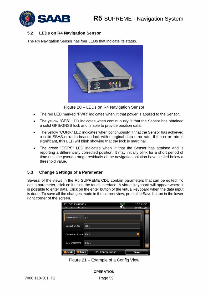
R5 SUPREME - Navigation System
OPERATION
7000 118-301, F1 Page 59
5.2 LEDs on R4 Navigation Sensor
The R4 Navigation Sensor has four LEDs that indicate its status.
Figure 20 – LEDs on R4 Navigation Sensor
The red LED marked “PWR” indicates when lit that power is applied to the Sensor.
The yellow “GPS” LED indicates when continuously lit that the Sensor has obtained a solid GPS/GNSS lock and is able to provide position data.
The yellow “CORR” LED indicates when continuously lit that the Sensor has achieved a solid SBAS or radio beacon lock with marginal data error rate. If the error rate is significant, this LED will blink showing that the lock is marginal.
The green “DGPS” LED indicates when lit that the Sensor has attained and is reporting a differentially corrected position. It may initially blink for a short period of time until the pseudo range residuals of the navigation solution have settled below a threshold value.
5.3 Change Settings of a Parameter
Several of the views in the R5 SUPREME CDU contain parameters that can be edited. To edit a parameter, click on it using the touch interface. A virtual keyboard will appear where it is possible to enter data. Click on the enter button of the virtual keyboard when the data input is done. To save all the changes made in the current view, press the Save button in the lower right corner of the screen.
Figure 21 – Example of a Config View

R5 SUPREME - Navigation System
OPERATION
7000 118-301, F1 Page 60
It is also possible to use buttons on the front of the R5 SUPREME CDU to select and change a parameter. Use the ARROW KEYPAD to select a parameter, currently selected parameter will be marked with an orange rectangle (See figure above). Press ENTER to popup the virtual keyboard. Use the ARROW KEYPAD to highlight the desired character and press ENTER to select it. Navigate to enter button of the virtual keyboard and press ENTER when done.
Figure 22 – Example of Virtual Keyboards

R5 SUPREME - Navigation System
OPERATION
7000 118-301, F1 Page 61
5.4 System Menus - Tree View

R5 SUPREME - Navigation System
OPERATION
7000 118-301, F1 Page 62
5.5 Navigating in Menus
To navigate in the R5 SUPREME CDU menus, simply press the menu button corresponding to the desired view using the touch interface, or use the ARROW KEYPAD buttons < > and
∧ ∨ to navigate between the view buttons. The currently selected button will be marked with an orange outline and orange text. Press the ENTER button to enter the currently selected view. In the lower left corner of a view there is also a Back button to quickly go back to previous view and a Main button to go directly to the Main Menu view.
Figure 23 – Main Menu Figure 24 – Navigate Menu
5.6 Alarm and Alert Pop-ups
The R5 SUPREME Navigation System features alarm and alert pop-ups that can appear any time during operation. To acknowledge an alarm or alert message, click on the buttons of the pop-up using the touch display or use the arrow buttons on the R5 SUPREME CDU to navigate between buttons and press ENTER.
Figure 25 – Alarm Popup

R5 SUPREME - Navigation System
OPERATION
7000 118-301, F1 Page 63
5.7 Status Bar
The top of the screen on the R5 SUPREME CDU always displays a summary of the system’s status.
Figure 26 – Status Bar
The left part of the status bar can either show the current position in latitude and longitude, or the name of the next waypoint in the currently active route. This is configurable with the “Status Information” parameter described in section 4.2.1. The status icons are displayed in the middle of the status bar and on the right the current time and currently used RAIM level is displayed. The time is either UTC or local (LOC) depending on the time configuration parameters described in section 4.2.8.
5.7.1 Status Icons
The status icons that can be shown in the R5 Navigation System are:
Unread DGPS message
Active alarms
Operating in GPS mode
Operating in GNSS mode
Navigating without differential corrections.
Using differential correction applied through User Port 1.
Using differential correction applied through User Port 1, Integrity Alert.
Using correction from internal radio beacon receiver (DGPS/DGNSS version)
Using correction from internal radio beacon receiver (DGPS/DGNSS version), Integrity Alert
Using differential corrections from SBAS.
Using differential corrections from SBAS, Integrity Alert.
No valid position information.
No communication with the R4 Navigation Sensor.
HDOP status indication (active if HDOP is above 4).
Navigation Sensor configured to use differential corrections but no differential corrections are used.
Current position Status icons
Current RAIM Level
Current time

R5 SUPREME - Navigation System
OPERATION
7000 118-301, F1 Page 64
With Synchronization status icon , being one of
CDU units are in sync..
CDU units are synchronizing databases.
CDU units are NOT in sync
Lost connection to other units.
The CDU is a slave display that is in sync with master.
The CDU is a slave display that is synchronizing databases with master.
The CDU is a slave display that is NOT in sync with master.
The CDU is a slave display that has lost connection to master.
5.7.2 RAIM Accuracy Level
The RAIM accuracy level specifies (in meters) the desired position accuracy used to calculate current RAIM status. RAIM is an integrity monitoring scheme that evaluates the quality of position data and compares it to the specified accuracy level.
The RAIM LED on the front of the R5 SUPREME CDU will show the RAIM status. A green RAIM LED indicates safe state; the calculated position accuracy is better than the set accuracy level. A yellow RAIM LED indicates caution state; the system is unable to safely determine if the position accuracy is better or worse than the set accuracy level. The red RAIM LED indicates unsafe state; the calculated position accuracy is worse than the set accuracy level.
The used RAIM accuracy level is the latest specified accuracy level, either specified manually or by a leg setting in the active route.
5.8 Navigate Menu
The Navigate menu contains a set of views related to typical ship navigation tasks during normal voyage operation.

R5 SUPREME - Navigation System
OPERATION
7000 118-301, F1 Page 65
Figure 27 – Navigate Menu
5.8.1 Show Current Position
Figure 28 – Position View
The R5 SUPREME Navigation System will power up in the Position view. The Position view shows current position, speed over ground (SOG) and course over ground (COG) as reported by the R4 Navigation Sensor. The position is represented by latitude and longitude. Current date and time, in UTC or local time, is also displayed.
If the navigation system is not able to calculate new position information, the latest valid information is shown in conjunction with the time when it was calculated. The red satellite icon in the status bar will indicate that no new position information is available. See section 5.7.1 “Status Icons” for further details on the icons.
Note: COG is based on track angle which requires that the ship is moving. Thus, COG data is not displayed when the SOG value is below 0.3 knots.
5.8.2 Anchor Watch
The Anchor Watch view provides functionality for activation of an alarm when the dis-placement from a reference position exceeds a certain limit. The view is accessed from Main Menu Navigate Anchor Watch. In order for an external or audible anchor watch alarm to be generated, the anchor watch alarm must be enabled in the Alarm Config view accessed from Main Menu Maintenance Configuration Alarm.
When entering the Anchor Watch view, the following will be displayed:

R5 SUPREME - Navigation System
OPERATION
7000 118-301, F1 Page 66
Figure 29 – Anchor Watch
5.8.2.1 Set Anchor Watch Alarm Distance
To set the alarm distance, click on the alarm distance edit field (marked with an orange square in the picture above). A virtual numpad will appear where it is possible to set the new value for the anchor alarm distance. Press on the enter button of the virtual numpad when done. The alarm distance must be within 1 to 1500 meters. The unit used for definition of the anchor watch alarm limit as well as for display of the current range to the reference position is configurable, as described in section 4.2.9 “Units”.
Figure 30 – Input of Anchor Watch Alarm Distance
5.8.2.2 Activate Anchor Watch
Press the ”Begin Watch” button to activate the anchor watch function. The current position will be captured as the reference position. The distance to the reference position will be calculated and compared to the configured alarm distance on a regular basis. The bearing and range from current position to reference position is displayed and illustrated below.
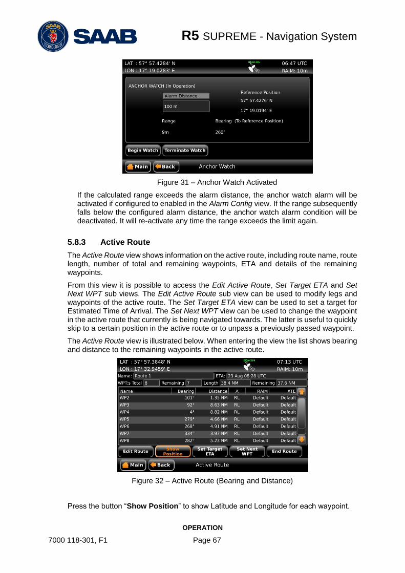
R5 SUPREME - Navigation System
OPERATION
7000 118-301, F1 Page 67
Figure 31 – Anchor Watch Activated
If the calculated range exceeds the alarm distance, the anchor watch alarm will be activated if configured to enabled in the Alarm Config view. If the range subsequently falls below the configured alarm distance, the anchor watch alarm condition will be deactivated. It will re-activate any time the range exceeds the limit again.
5.8.3 Active Route
The Active Route view shows information on the active route, including route name, route length, number of total and remaining waypoints, ETA and details of the remaining waypoints.
From this view it is possible to access the Edit Active Route, Set Target ETA and Set Next WPT sub views. The Edit Active Route sub view can be used to modify legs and waypoints of the active route. The Set Target ETA view can be used to set a target for Estimated Time of Arrival. The Set Next WPT view can be used to change the waypoint in the active route that currently is being navigated towards. The latter is useful to quickly skip to a certain position in the active route or to unpass a previously passed waypoint.
The Active Route view is illustrated below. When entering the view the list shows bearing and distance to the remaining waypoints in the active route.
Figure 32 – Active Route (Bearing and Distance)
Press the button “Show Position” to show Latitude and Longitude for each waypoint.

R5 SUPREME - Navigation System
OPERATION
7000 118-301, F1 Page 68
Figure 33 – Active Route (Position)
Press “Show Acc. Dist.” to show the accumulated distance along the route to each waypoint.
Figure 34 – Active Route (Accumulated Distance)
Press “Show WPT ETA” to show the estimated time of arrival to each waypoint in the route.
Figure 35 – Active Route (WPT ETA)
Press “Show BRG/DIST” to show the initial view again.

R5 SUPREME - Navigation System
OPERATION
7000 118-301, F1 Page 69
5.8.3.1 Edit Active Route
Press “Edit Route” to enter the Edit Active Route view. This view is used to modify the active route. It displays all waypoints and legs in the active route, regardless if they are passed or not and including waypoints created when resetting cross-track error in the Navigation Info view. It is possible to modify navigation algorithm, cross-track error limit and RAIM setting for each leg, as well as remove, modify and insert waypoints. When entered, the view displays all the waypoints of the route, as illustrated below.
Figure 36 – Edit Active Route
When saving the active route, a popup will appear where it is possible to choose if a change made to the active route should leave the original route unaffected or if the changes should be saved in the route database as well. Press “Yes” to affect both active route and the route in the database. Press “No” to only affect the active route.
Figure 37 – Save changes in Edit Active Route
Note: Waypoints named “Reset XTE ...” have been inserted into the route when resetting the cross-track error. When saving changes, they will not be stored. The
original route will not be affected by changes made to legs towards or between such
waypoints, nor will such legs be created in the original route. These waypoints are not viewed as part of the planned route.

R5 SUPREME - Navigation System
OPERATION
7000 118-301, F1 Page 70
5.8.4 Navigation Aid
The Navigation Aid view presents fundamental navigation data and aids the user in navigating towards a waypoint and following a route. It presents information such as the bearing and range to the next waypoint, the ship’s current course over ground (COG) and speed over ground (SOG) and current cross-track error (if sailing on a route).
Figure 38 – Navigation Aid
The upper scale shows COG for own ship, indicated with a grey coloured triangle pointing upwards, as well as bearing to next waypoint relative north which is indicated with a cyan coloured triangle pointing downwards. The difference between present course and the “course to head” to exactly navigate towards next waypoint is illustrated by the distance between the two triangles. To steer towards the waypoint, make the waypoint symbol (cyan triangle) stand directly above the ship symbol (grey triangle).
If sailing on a route and having reached the first waypoint, the lower scale indicates the current cross-track error, illustrated by the horizontal yellow coloured line. The vertical black and yellow indicators are the currently used cross-track error limit. If the cross-track error exceeds the limit on either side, the “XTE Exceeded” alarm will become active. If the horizontal yellow coloured line is to the right of the centre line in the lower scale, it means that the ship is on the right side of the current leg.
To more quickly reduce the cross-track error, steer back towards a point on current leg closer than the next waypoint. If the cross-track error is to the right of the centre line in the lower scale, the grey triangle in the upper scale should be to the left of the cyan coloured triangle to reduce the cross-track error as shown in the figure above.
5.8.5 Navigation Plot
The Plot view displays a plot over the active route, indicating the ship’s position, way-points, legs and cross-track error limit range for the current leg. It also shows current navigation information which are further described in section 5.8.6

R5 SUPREME - Navigation System
OPERATION
7000 118-301, F1 Page 71
Figure 39 – Navigation Plot
The next waypoint in the route is marked with a double circle and the currently active leg is shown in cyan colour. Other legs are shown in magenta colour and their waypoints are marked with a single circle. In the bottom right corner of the plot is a compass indicator that points towards true north.
The buttons on the right side of the Navigation Plot view are described below.
1) Move the plot up
2) Move the plot to the right
3) Move the plot to the left
4) Move the plot down
5) Zoom out
6) Zoom in
7) Centre plot on own ship
8) Reset zoom
9) Enables/disables ship track
10) Skip the next waypoint in route and switch to next leg
11) Switch between ship up / north up view in plot
5.8.6 Navigation Info
The Navigation Info view presents fundamental navigation data and aids the user in navigating towards a waypoint and following a route. It presents information such as the bearing and range to the next waypoint, the ship’s current course over ground (COG) and speed over ground (SOG) and current cross-track error (if sailing on a route).
Figure 40 – Navigation Info View
1
2 3
4
5 6
7 8
9
10
11

R5 SUPREME - Navigation System
OPERATION
7000 118-301, E1 Page 72
The left part of the Navigation Info view presents current navigation information. In Figure 40, an example of the Navigation Info view is shown. The information shown of the left side of the view is explained below:
NAV RL to WP5
This means that the next waypoint in the current route is named “WP5” and we are currently using the navigation algorithm “Rhumb Line” (RL) to calculate range and bearing to the waypoint.
BRG
Bearing to the next waypoint.
COG
The ship’s course over ground relative true north.
Note: COG is based on track angle which requires that the ship is moving. Thus, COG data is not displayed when the SOG value is below 0.3 knots.
RNG
Range to the next waypoint. The unit for range is configurable in the Units view, see section 4.2.9.
SOG
The ship’s speed over ground. The unit for SOG is configurable in the Units view, see section 4.2.9.
TTW
Time To Waypoint – The estimated time left to next waypoint.
CTS
Course to steer – The calculated course to steer compensates for the current set and drift and calculates a course to steer to make the COG match the BRG. Heading sensor input is required to calculate CTS. This value is outputted as the heading to steer value in the APB and HSC sentences.
VMG
Velocity Made Good – The velocity component that is pointing towards the next waypoint. If the COG value is the same as the BRG to next waypoint, the VMG value will be the same as the SOG as all the ship’s velocity is heading directly towards the waypoint.
XTE
Cross track error – The distance between the ship’s position and the current leg of the route. If the character “<” is displayed, it means that the ship’s position is to the left of the leg and if the character “>” is displayed, the ship’s position is to the right of the leg.
XTE Limit
The cross track error limit that is used on the current leg. If the cross track error value exceeds this limit, the XTE alarm will be activated. All the legs of a route will automatically use the default XTE limit which is configurable in the Navigation Configuration view, see section 4.2.1. It is also possible to have a special XTE limit on a certain leg by editing the leg settings. This is described in section 5.8.3.1.

R5 SUPREME - Navigation System
OPERATION
7000 118-301, E1 Page 73
5.8.6.1 Reset XTE
The cross track error can be set to zero by inserting a temporary waypoint at the current position in the active route. The temporary waypoint will not be saved if the active route. To reset the cross track error, press the button “Reset XTE”.
5.8.6.2 Skip Next Waypoint
To skip the next waypoint and manually switch leg on the active route, press the button ”Skip Waypoint”.
The right part of the Navigation Info view can show several different sub views which can be accessed by pressing the button “Next Page”. The sub views are described below.
5.8.6.3 Estimated Time of Arrival (ETA)
Figure 41 – Navigation Info View - ETA
This sub view show the estimated time of arrival (ETA) to the last waypoint in the current route if the current speed over ground (SOG) is maintained.
It is also possible for the user to set a “Target ETA”, i.e. a desired time when the last waypoint in the current route should be reached. If a “Target ETA” is set, the sub view will show a “Target SOG” which is the average speed that must be maintained to reach the last waypoint of the route at the time specified by “Target ETA”. The “Target ETA” setting is accessed from Main Menu Navigate Active Route Set Target ETA.
5.8.6.4 Waypoint Information
The waypoint information sub view shows the names of the active route, next waypoint and previous waypoint.

R5 SUPREME - Navigation System
OPERATION
7000 118-301, E1 Page 74
Figure 42 – Navigation Info View – WPT Info
5.8.6.5 Set and Drift
The Set and Drift sub view show information received from heading sensors, depth sensors and speed sensors. This information together with SOG and COG is also used to calculate set and drift. To receive information from heading and depth sensors, the input ports must be configured. See section 4.2.14 Compass Data Port and 4.2.15 Depth Data Port for more information.
Figure 43 – Navigation Info View – Set and Drift
Note: Set and Drift calculations require speed through water and heading sensor inputs, as well as valid SOG and COG readings.
5.8.6.6 Next Waypoint Plot
This sub view shows a plot of the remaining part of the current leg as well as the next leg. The plot will automatically adjust the zoom level when the ship is closing on the next waypoint. To view a more detailed plot of the entire route and to zoom manually, see section 5.8.5.

R5 SUPREME - Navigation System
OPERATION
7000 118-301, E1 Page 75
Figure 44 – Navigation Info View – Plot
5.9 Voyage Menu
The Voyage Menu can be accessed from the Main Menu and contains views for voyage planning, viewing and creating waypoints and routes as well as tidal predictions and scheduled alerts.
Figure 45 – Voyage Menu
5.9.1 Route List
A route is a sequence of waypoints, which is used to navigate from a start waypoint to an end waypoint. The R5 Navigation System supports up to 128 different routes and each route can consist of up to 512 waypoints (with a total maximum of 4000 unique waypoints in the system).
All stored routes are edited and controlled in the Route List view and its sub views. This excludes the active route, which is the route that currently is being sailed and handled completely separate in the Active Route view, described in section 5.8.3.
The Route List view presents the routes currently stored in the R5 SUPREME CDU, and provides sub views to view and edit a route as well as creates new routes. The Route List view also contains functionality to delete routes and find a route by name.

R5 SUPREME - Navigation System
OPERATION
7000 118-301, E1 Page 76
Figure 46 – Route List
5.9.1.1 Sail a Route
To start sailing a route, select the desired route in the Route List view and press the button ”Sail Route”. The Sail Route view will be shown.
Figure 47 – Sail Route View
This view shows details of the selected route, including name, length, legs and waypoints. It provides functionality for sailing the route in forward or reverse direction. The view can either display the waypoints or the legs of the route. When viewing the legs, the specific leg settings for navigation algorithm, RAIM level and XTE limit are shown. The navigation algorithm can be either GC (Great Circle) or RL (Rhumb Line). The navigation algorithm used when sailing towards the first waypoint in a route or towards a single waypoint is determined by the default navigation algorithm parameter set in the Navigation Configuration view described in section 4.2.1.
The RAIM level and XTE limit can be set to a specific value for the leg or using the default settings determined by the parameters in the Navigation Configuration view.
Press the button “Sail Forward” to sail the route from the first waypoint to the last. Press the button “Sail Reverse” to sail the route from last waypoint to the first. A valid position is required to start sailing a route.
5.9.1.2 Sail Directly to a Specific Location (Waypoint)
In the Route List view, press the button “Sail To WPT” to show the Sail To view, which is used to sail from current position to a destination waypoint.

R5 SUPREME - Navigation System
OPERATION
7000 118-301, E1 Page 77
Figure 48 – Sail To View
Either an existing waypoint can be used, or a new destination waypoint can be created. The new waypoint can be created by either specifying latitude and longitude or by specifying range and bearing from current position. To select or create a destination, press the button “Select DEST”. The Insert Waypoints view will be shown.
Figure 49 – Insert Waypoints View
Choose an existing waypoint
1. Select a waypoint in the list; it will be highlighted when selected.
2. Press the button “Select Waypoint” to transfer the waypoint to the “Insert List” to the right.
3. Press “Insert” to choose the waypoint as destination in the Sail To view.
4. Press “Sail” in the Sail To view to start sailing towards the chosen destination.
Create a new waypoint by specifying latitude and longitude
1. Press the button “Create New WPT” to show the Create New Waypoint view.
2. Press on the “Name” edit field and enter a new name for the destination.
3. Press the “LAT” edit field to input latitude.
4. Press the “LON” edit field to input longitude.
5. Press “Save” to choose the new waypoint as destination in the Sail To view.
6. Press “Sail” in the Sail To view to start sailing towards the chosen destination.

R5 SUPREME - Navigation System
OPERATION
7000 118-301, E1 Page 78
Figure 50 – Create New Waypoint – Latitude and Longitude
Create a new waypoint by specifying bearing and range
1. Press the button “Create New WPT” to show the Create New Waypoint view.
2. Press on the “Name” edit field and enter a new name for the destination.
3. Press the button “Bearing/Range”. A popup window will appear:
Figure 51 – Create New Waypoint – Range and Bearing
4. Press on the “Bearing” edit field and enter a bearing from the current position.
5. Press the “Range” edit field and enter a range from the current position.
6. The calculated position will be shown at the bottom of the popup window.
7. Press OK when done.
8. Press “Save” in the Create New Waypoint view to choose the new waypoint as destination in the Sail To view.
9. Press “Sail” in the Sail To view to start sailing towards the chosen destination.

R5 SUPREME - Navigation System
OPERATION
7000 118-301, E1 Page 79
Figure 52 – Sail To View with Selected Destination
5.9.1.3 Edit a Route
The Edit Route view enables the user to modify a route. It is possible to insert waypoints as well as whole existing routes into the route being edited. It is also possible to remove and edit waypoints and change settings such as navigation algorithm, RAIM level and XTE limit for each leg in the route. The route name can also be modified.
A waypoint or route inserted first or last in the route being edited results in the creation of a new leg connecting it to the edited route. Such a leg will initially have the default settings for navigation algorithm, RAIM level and XTE limit as described in section 4.2.1.
A waypoint or route inserted in between two existing waypoints is however seen as splitting the original leg in two. Both the connecting legs to the inserted waypoint or route will in this case have the same settings as the original leg had.
It is also possible to add multiple waypoints in one insert. In this case the legs connecting the inserted waypoints will have the same leg settings as the connecting leg(s).
To edit a route in the route list, enter the Edit Route view by selecting the route in the route list, then press on the button “Route” to popup a list of actions and select “Edit”.
Figure 53 – Route List View – Edit

R5 SUPREME - Navigation System
OPERATION
7000 118-301, E1 Page 80
The Edit Route view can either show a list of all waypoints or a list of all legs in the route. When the waypoints are shown, it is possible to insert new waypoints or even complete routes into the existing route. When the legs are shown it is possible to change the navigation algorithm, RAIM level and XTE limit for each individual leg. To switch between waypoint view and leg view, press the button “Show Legs/Show WPs”.
Figure 54 – Edit Route View
Change name of route
1. Press the “Name” edit field at the top of the Edit Route view. A virtual keyboard will appear.
2. Type in the new name on the virtual keyboard. Press the virtual keyboard enter button when done.
3. Press “Save” to save the route with the new name and exit to Route List view.
Insert waypoints into the route
1. Make sure that the Edit Route view shows the waypoints (press “Show WPs” if the leg view is shown).
2. Select the waypoint in the route which new waypoints should be inserted before or after.
3. Press the button “Insert” followed by “WPT Before” or “WPT After”. The Insert Waypoints view will be shown:
Figure 55 – Insert Waypoints View
4. Highlight the desired waypoint and press the button “Select Waypoint” to add it to the “Insert List” on the right of the Insert Waypoints view.
5. If more waypoints are to be inserted, repeat step ‘4’.
6. Press the button “Insert” to insert all the waypoints from the “Insert List” into the route being edited and exit to the Edit Route view.

R5 SUPREME - Navigation System
OPERATION
7000 118-301, E1 Page 81
7. Press “Save” in the Edit Route view to save changes in the edited route and exit to Route List view.
Insert existing route into the route being edited
1. Make sure that the Edit Route view shows the waypoints (press “Show WPs” if the legs are shown).
2. Select the waypoint in the route which the route should be inserted before or after.
3. Press the button “Insert” followed by “RTE Before” or “RTE After”.
4. The Insert Route view is displayed:
Figure 56 – Insert Route View
5. Highlight the desired route in the list and press “Insert” to insert all the waypoints from the chosen route into the route being edited.
6. Press “Save” in the Edit Route view to save changes in the edited route and exit to Route List view.
Change navigation algorithm, RAIM level and XTE limit for a leg in the route
1. Make sure that the Edit Route view shows the legs (press “Show Legs” if the waypoints are shown).
2. Select the leg to modify in the list and press the button “Edit Leg”. The Edit Leg view is displayed:
Figure 57 – Edit Leg View
3. The Navigation Algorithm, RAIM Accuracy and XTE Limit parameters can be set to “Default” or to a specific value. If set to default, the settings in the Navigation Configuration view will be used, as described in section 4.2.1.
4. To change the navigation algorithm, press the “Navigation Algorithm” droplist and choose “Algorithm”. A new drop list will appear where it is possible to choose between “Rhumb Line” and “Great Circle”. Select the desired value in the new drop list.

R5 SUPREME - Navigation System
OPERATION
7000 118-301, E1 Page 82
5. To change the RAIM accuracy level for the leg, press the “RAIM Accuracy” droplist and choose “RAIM Level”. A new edit field will appear. Click on the “Level” edit field to input a desired RAIM accuracy level in meters.
6. To change the XTE Limit for the leg, press the “XTE Limit” droplist and choose “XTE Limit”. A new edit field will appear. Click on the “Limit” edit field to input a desired XTE Limit.
7. Press the button “Save” to save changes made to leg and exit to the Edit Route view.
8. Press “Save” in the Edit Route view to save changes in the edited route and exit to Route List view.
Remove waypoint from the route
1. Make sure that the Edit Route view shows the waypoints (press “Show WPs” if the legs are shown)..
2. Highlight the waypoint that is about to be removed.
3. Press the button “Waypoint” followed by “Remove”.
4. Press “Save” to save changes in the edited route and exit to Route List view.
Replace waypoint in the route
1. Make sure that the Edit Route view shows the waypoints (press “Show WPs” if the legs are shown)..
2. Highlight the waypoint that should be replaced.
3. Press the button “Waypoint” followed by “Replace”. The Replace Waypoint view is shown:
Figure 58 – Replace Waypoint View
4. Highlight the desired waypoint and press the button “Select Waypoint” to add it to the “Insert List” on the right of the Replace Waypoint view.
5. Press the button “Insert” to replace the original waypoint with the one from the “Insert List” and exit to Edit Route view.
6. Press “Save” to save changes in the edited route and exit to Route List view.
Reverse Route
1. To reverse the route, press the button “Reverse Route”.
2. Press “Save” to save changes in the edited route and exit to Route List view.

R5 SUPREME - Navigation System
OPERATION
7000 118-301, E1 Page 83
5.9.1.4 Create a New Route
The Create Route view is used to create a new route. A default name is supplied but should be changed to a descriptive name for the new route. A route can be created from the Route List view by pressing the button “Create” and then pressing on of the buttons “New RTE” or “RTE From”.
Figure 59 – Route List View – Create New Route
When pressing “RTE From” the Create Route view is displayed with information entered from the selected source route. When pressing “New RTE” the Create Route view will be empty.
Figure 60 – Create Route View
Specify name of route
1. Press the “Name” edit field at the top of the Create Route view. A virtual keyboard will appear.
2. Type in the new name on the virtual keyboard. Press the virtual keyboard enter button when done.
Insert waypoints and edit leg information
Press the button “Insert” followed by “WPT” to insert waypoints or “RTE” to insert existing routes. The functions in the Create Route view are the same as in Edit Route view. See section 5.9.1.3 for more information.
5.9.1.5 Find a Route by Name
It is possible to search for a route in the route list by entering the name, if the route is found it will automatically be highlighted in the Route List view.
1. Press the button “Route” followed by “Search by Name”.
2. Enter the name of the route and press the enter button on the virtual keyboard.

R5 SUPREME - Navigation System
OPERATION
7000 118-301, E1 Page 84
5.9.1.6 View a Route
The View Route view is similar to the Sail Route view described in section 5.9.1.1, as it shows the same details of the route. Either the waypoints or the legs of the route are shown. Each waypoint is displayed with name and position, and for each leg the length and initial bearing is shown as well as the navigation algorithm, RAIM accuracy level and XTE limit.
To view a route, select it in the route list and press the button “Route” followed by “View”.
Figure 61 – View Route View
5.9.1.7 Upload Route to External Systems
The R5 SUPREME CDU can send routes and associated waypoints to an external system via one of the serial User Ports or via the Light Weight Ethernet network. In order to upload routes and waypoints the user ports must be configured with correct baud rate and the sentence “WPL/RTE (Upload)” must be enabled in the output configuration for each port where the routes and waypoints should be output. To configure the user ports, see section 4.2.12 and 4.2.17.
To upload a route and associated waypoints on the configured user ports, select a route in the route list; press the button “Upload Route” followed by “Selected”. The selected route will now be output on each port that has the sentence “WPL/RTE (Upload)” enabled. To upload all routes in the route list, press “Upload Route” followed by “All”.
5.9.1.8 Delete a Route
1. Select the route to be deleted in the route list.
2. Press the button “Route” followed by “Delete”.
3. A confirmation popup will appear, press “Yes” to delete the route. This will only delete the selected route; the associated waypoints will still be available.
5.9.1.9 Delete All Routes
1. Press the button “Route” followed by “Delete All”.
2. A confirmation popup will appear, press “Yes” to delete all the routes in the system. This will only delete the routes; the associated waypoints will still be available.

R5 SUPREME - Navigation System
OPERATION
7000 118-301, E1 Page 85
5.9.2 Waypoint List
Waypoints are the basis for ship navigation. A waypoint is a position on the earth surface that is given a unique name and stored in the memory of the R5 SUPREME CDU. Waypoints can be entered in several different ways, and used for building routes as well as for direct navigation to a specific position.
The Waypoint List view lists all the waypoints that are currently stored in the R5 Navigation System. Via this view it is also possible to create new waypoints and store them in the memory.
Figure 62 – Waypoint List View
5.9.2.1 Sail To Waypoint
1. Select the desired destination waypoint in the list.
2. Press the button “Sail to WPT”. The Sail To view will be shown:
Figure 63 – Sail To View
3. Press the button “Sail” to start sailing towards the selected waypoint.
5.9.2.2 Edit a Waypoint
1. Select the desired waypoint in the list.
2. Press the button “WPT” followed by “Edit”.
3. Press the “Name” edit field to edit the name of the waypoint.
4. Press the “LAT” edit field to edit the latitude of the waypoint.
5. Press the “LON” edit field to edit the longitude of the waypoint.
6. Press the button “Current Position” to fill in the current position as latitude and longitude of the waypoint.
7. Press the button “Bearing/Range” to calculate a new latitude and longitude by specifying a range and bearing from the waypoint’s current position.

R5 SUPREME - Navigation System
OPERATION
7000 118-301, E1 Page 86
8. Press “Save” to save any changes made to the waypoint.
Figure 64 – Edit/Create Waypoint
5.9.2.3 Create a New Waypoint
1. Press the button ”Create” followed by ”New WPT”.
2. Press the “Name” edit field to enter the name of the waypoint.
3. Press the “LAT” edit field to enter the latitude of the waypoint.
4. Press the “LON” edit field to enter the longitude of the waypoint.
5. Press the button “Current Position” to fill in the current position as latitude and longitude for the waypoint.
6. Press the button “Bearing/Range” to calculate a new latitude and longitude by specifying a range and bearing from the waypoints current position.
7. Press “Save” to save the new waypoint.
5.9.2.4 Create a New Waypoint from an Existing Waypoint
1. Select a waypoint in the list to use as a base for the new waypoint.
2. Press the button ”Create” followed by ”WPT From”. The Edit/Create Waypoint view will be shown with the name, latitude and longitude copied from the selected waypoint.
3. Press the “Name” edit field to enter the name of the waypoint.
4. Press the “LAT” edit field to enter the latitude of the waypoint.
5. Press the “LON” edit field to enter the longitude of the waypoint.
6. Press the button “Current Position” to fill in the current position as latitude and longitude for the waypoint.
7. Press the button “Bearing/Range” to calculate a new latitude and longitude by specifying a range and bearing from the waypoints current position.
8. Press “Save” to save the new waypoint.
5.9.2.5 Find a Waypoint by Name
It is possible to search for a waypoint in the waypoint list by entering the name, if the waypoint is found it will automatically be highlighted in the Waypoint List view.
1. Press the button “Search by Name”.

R5 SUPREME - Navigation System
OPERATION
7000 118-301, E1 Page 87
2. Enter the name of the waypoint and press the enter button on the virtual keyboard.
5.9.2.6 Upload Waypoints to External Systems
The R5 SUPREME CDU can send waypoints to an external system via one of the serial User Ports or via the Light Weight Ethernet network. In order to upload waypoints, the user ports must be configured with correct baud rate and the parameter “WPL/RTE (Upload)” must be enabled for each port that the waypoints should be output. To configure the user ports, see section 4.2.12 and 4.2.17.
To upload a waypoint on the configured user ports, select a waypoint in the waypoint list; press the button “Upload WPT” followed by “Selected”. The selected waypoint will now be output on each port that has the parameter “WPL/RTE (Upload)” enabled. To upload all waypoints in the waypoint list, press “Upload WPT” followed by “All”.
5.9.2.7 Delete a Waypoint
1. Select the waypoint to be deleted in the waypoint list
2. Press the button “WPT” followed by “Delete”.
3. A confirmation popup will appear, press “Yes” to delete the waypoint. It is NOT possible to delete a waypoint that is used by any route. If the selected waypoint is included in one or more routes a popup will be displayed showing which routes includes it.
5.9.2.8 Delete All Waypoints and Routes
1. Press the button “WPT” followed by “Delete All”.
2. A confirmation popup will appear, press “Yes” to delete all the waypoints and all the routes in the system.
5.9.3 Scheduled Alerts
The Scheduled Alerts view allows the user to create and inspect alerts scheduled to activate alarms at certain points in time.
There are two types of alerts that may be scheduled. Time alerts are activated at a specific time and can be set to be a single alarm or a recurring alarm with a certain time interval. ETA alerts will be activated at certain time prior to ETA of the current active route.
When a scheduled alert is activated, a popup will appear and the R5 CDU buzzer will be activated if scheduled alert sound parameter is set to “Beep” or “Continuous” in Sound Config view as described in section 4.3.6.

R5 SUPREME - Navigation System
OPERATION
7000 118-301, E1 Page 88
Figure 65 – Scheduled Alerts View
5.9.3.1 Create Time Alert
1. To create a new time alert, press the button “Create Time Alert”. The Create Time Alert view is shown:
Figure 66 – Create Time Alert View
2. To edit the alert text that is shown in the popup, press the “Alert Text” edit field. A virtual keyboard will appear. Enter the desired alert text and press enter on the virtual keyboard.
3. Edit the start time of the alert by pressing the “Start Time” edit field. A virtual numpad will appear. Enter the desired date and time and press enter on the virtual numpad.
4. Select if the time alert should be a single alert or a recurring alert by pressing on the drop list “Alert Type”.
5. If the alert is recurring, select the time interval by pressing on the “Hours” edit field and “Minute” edit field.
6. Press “Save” to set the alert.
5.9.3.2 Create ETA Alert
1. To create a new ETA alert, press the button “Create ETA Alert”. The Create ETA Alert view is shown:

R5 SUPREME - Navigation System
OPERATION
7000 118-301, E1 Page 89
Figure 67 – Create ETA Alert View
2. To edit the alert text that is shown in the popup and, press the “Alert Text” edit field. A virtual keyboard will appear. Enter the desired alert text and press enter on the virtual keyboard.
3. Select if the ETA alert should be set for the current active route only or for all future active routes as well by pressing the drop list named “Type” and choose “Single”(Current route) or “Every Route”.
4. Edit the time before ETA of the active route when the ETA alert should be activated by pressing on the “Hours” edit field and “Minute” edit field.
5. Press “Save” to set the alert.
5.9.3.3 Edit Scheduled Alert
1. Select the alert to edit in the alert list of the Scheduled Alerts view.
2. Press the button “Edit Alert” to show the Edit Alert view.
3. Edit the parameters as described in sections 5.9.3.1 and 5.9.3.2.
4. Press “Save” to save the changes.
5.9.3.4 Delete Scheduled Alert
1. Select the alert to delete in the alert list of the Scheduled Alerts view.
2. Press the button “Delete Alert”.
5.9.3.5 View Scheduled Alert
1. Select the alert to view in the alert list of the Scheduled Alerts view.
2. Press the button “View Alert”. The View Time Alert view or View ETA Alert view will be shown where details about the selected alert are displayed.
3. Press “Back” to exit to the Scheduled Alert view again.
5.10 Tidal Predictions
The R5 SUPREME CDU can be used for calculation of tidal predictions based on user input of data from the Admiralty Tide Tables published by the U.K Hydrographic Office.
The user is required to input data for the specific port and select the point in time for which the prediction is to be calculated.
The tidal prediction features can be accessed by pressing Main Menu Voyage Tide.

R5 SUPREME - Navigation System
OPERATION
7000 118-301, E1 Page 90
Note that meteorological effects (e.g wind and barometric pressure) as well as other factors not accounted for in the generalized tidal models may cause significant deviation between actual and predicted tide.
5.10.1 Calculation Method and Source Data for Tide
The tidal predictions are calculated by the so called ‘simplified harmonic method’. Harmonic constants and other parameters required are included in publications below. Note that the algorithms applied are specifically adapted for this data. Tidal parameters obtained from other sources shall not be used with the R5 SUPREME CDU tidal calculations.
Predictions calculated according to this method will not be fully consistent with the tabulated high/low and hourly predictions from the Admiralty tide tables. This is due to the fact that the tabulated values are based on a more extensive data set compared to the limited number of parameters used by the simplified harmonic method.
The source data is split between volumes with different geographical coverage as follows:
U.K Hydrographic Office ADMIRALTY TIDE TABLES (ATT)
Volume 1 (NP 201): United Kingdom and Ireland (including European channel ports)
Volume 2 (NP 202): Europe (excluding United Kingdom and Ireland), Mediterranean Sea and Atlantic Ocean
Volume 3 (NP 203): Indian Ocean and South China Sea
Volume 4 (NP 204): Pacific Ocean
Optionally, for European ports, ATT Volume 1 and European part of Volume 2 can be substituted by: TIDAL HARMONIC CONSTANTS, EUROPEAN WATERS (NP 160).
5.10.2 Input of Tidal Parameters
Tidal data for a new port is entered as follow:
1. Enter the Tide Plot view by pressing Main Menu Voyage Tide. The Tide Plot view will be displayed as shown below:
Figure 68 – Tide Plot with No Port Selected
2. Click on the button “Select Location” to enter the Port List view. This view will show all the ports that have been entered in the R5 SUPREME CDU.

R5 SUPREME - Navigation System
OPERATION
7000 118-301, E1 Page 91
Figure 69 – Port List
3. Click on the button “Add Port” to enter the Add Port view. Input the data for the tidal parameters from the relevant volume of ATT, part III.
Figure 70 – Add Port
4. Some ports have season or fortnightly variations in mean level and harmonic constants. If so, such variations can be input by selecting “Use Table…” in the corresponding drop list for the parameter.
Figure 71 – Add Port – Input Seasonal Variations
A new view will be shown where the variation values from the “Admiralty Tide Tables” can be input. Press “Apply” to use the variation values and return to the Add Port view.

R5 SUPREME - Navigation System
OPERATION
7000 118-301, E1 Page 92
Figure 72 – ML Seasonal Variations
5. In the Add Port view, press the button “Save” when all data for the port has been entered in order to store the new port and return to the Port List view.
The following data can be input for each port:
ID Port No. from ATT part III.
Name Place name from ATT part III.
Zone UTC offset time zone (UTC time – Local Time) in hours and minutes from ATT part III. This information is important since ATT data is referenced to a local time in port with this offset from UTC. Enter this data as defined in ATT regardless of adjustments for other local time offsets (e.g daylight savings time). See further notes on treatment of time offset in sections below.
Position Latitude and longitude of port. This is optional information that is not required for calculation of tides. If entered, the current distance to the actual port will be shown in the list of tidal stations. Position is not listed in ATT part III.
ML Z0 This is mean level in meters from ATT part III. For most stations this is a fixed value. Tables of seasonal corrections and fortnightly variations as required for some stations can be entered as described below.
ML Seasonal Seasonal corrections to the mean level value as defined for some ports. If so, this parameter shall be set to ‘Use Table…’ which will open a new view where values for each month can be input in accordance with the corrections listed in ATT part III.
ML Fortnightly Fortnightly variations in mean level as defined for some ports. If so, this parameter shall be set to ‘Use Table…’ which will open a new view where parameters should be entered from a supplementary table in ATT.
M2 g Harmonic constant from ATT part III.
M2 H.m Harmonic constant from ATT part III. Fixed value used for most ports.

R5 SUPREME - Navigation System
OPERATION
7000 118-301, E1 Page 93
M2 Seasonal Seasonal depending values of M2 H.m as defined for some ports. If so, this parameter shall be set to ‘Use Table…’ which will open a new view where values for each month can be input in accordance with values listed in ATT part III.
S2 g Harmonic constant from ATT part III.
S2 H.m Harmonic constant meters from ATT part III. Fixed value used for most ports.
S2 Seasonal Seasonal depending values of S2 H.m as defined for some ports. If so, this parameter shall be set to ‘Use Table…’ which will open a new view where values for each month can be input in accordance with values listed in ATT part III.
K1 g Harmonic constant from ATT part III.
K1 H.m Harmonic constant from ATT part III.
O1 g Harmonic constant from ATT part III.
O1 H.m Harmonic constant from ATT part III.
f4 Shallow water correction from ATT part III.
F4 Shallow water correction from ATT part III.
f6 Shallow water correction from ATT part III.
F6 Shallow water correction from ATT part III.
5.10.3 Use Tidal Predictions
Once port data has been entered, tidal predictions can be generated for that port as follows:
1. Enter the Tide Plot view by pressing Main Menu Voyage Tide
2. Click on the button “Select Location” to enter the Port List view.
3. Select the desired port in the port list and click on the button “Use Port”. The Tide Plot view is shown with a graphical prediction for the current day or a previously selected date.

R5 SUPREME - Navigation System
OPERATION
7000 118-301, E1 Page 94
Figure 73 – Tide Plot
The Tide Plot shows the predicted tides for the selected port and date. The port id and the port name are shown above the plot. The plot date is shown in the upper right corner. The orange dot in the plot marks the current time as derived from GPS/GNSS. The blue dot marks the time that is selected by the user. It is possible to click anywhere in the plot to move the blue dot or to click on the buttons “Select Previous H/L” and “Select Next H/L” to step between local high and local low points in the plot. It is also possible to move the marker with the ARROW KEYPAD button on the front of the R5 SUPREME CDU. Use the arrows to mark the plot and press ENTER. When the plot is selected the left and right arrow buttons can be used to move the blue dot.
In order to calculate predictions for another day, click on the button “Select Date” to access an almanac where any date can be chosen.
Figure 74 – Tide Plot, Select Date
The tide predictions can also be represented as a table by clicking on the button “Table”. The maximum and minimum values for the selected date will be highlighted.

R5 SUPREME - Navigation System
OPERATION
7000 118-301, E1 Page 95
Figure 75 – Tide Table
5.10.4 Units of Predicted Tide
Predicted tide can be displayed in meters, feet or fathom units as defined by the ‘Depth Unit’ configuration parameter. This parameter is accessed from the Units Configuration view described in section 4.2.9.
5.10.5 Treatment of Local Time Zones
For each port, a ‘Zone’ parameter shall be entered as defined in ATT part III. This parameter defines the relationship of data published in ATT with respect to UTC.
When a tide prediction is generated, a graph will be displayed for 00 to 24 hours of a selected date. This time will be in UTC or with any user selectable local time offset as defined in the Time Zone Settings view (see section 4.2.8). If UTC is used, times will be denoted ‘UTC’. If a local time frame is used, times will be denoted ‘LOC’. This is in analogy with how all times generally are treated by the R5 SUPREME CDU.
Thus, it is important to realize that a tide displayed in ‘LOC’ time is not necessarily the local time in the port (defined by the ‘Zone’ parameter). If this is desired, the user must manually define the local time in the Time Zone Settings view that corresponds to the ‘Zone’ value for the actual port.
To make things more complicated, the ‘Zone’ parameter in ATT part III is defined as (UTC time – Local Time) and thus being negative when moving eastwards from Greenwich. On the other hand, the local time offset in the Time Zone Settings view is to be added to UTC and therefore positive when moving eastwards. Thus, a negative ‘Zone’ value is equivalent to a positive offset of time configuration and vice versa.
In general: always enter ‘Zone’ for the port as indicated in ATT part III and select local time offset in Time Zone Settings view to obtain the desired local time frame for which the prediction is to be obtained.
Examples of ‘Zone’ setting and corresponding local time configuration are shown in the following two figures. Notice that the Zone setting for the port in this example is -01.00 hours as indicated by ATT part III while the corresponding local time configuration in the Time Config view is +01.00 hours. This will ensure that predictions in the Tidal Plot view are calculated and shown in the ports local time.

R5 SUPREME - Navigation System
OPERATION
7000 118-301, E1 Page 96
Figure 76 – Edit Port, Zone Setting
Figure 77 – Time Zone Settings for the R5 SUPREME CDU
5.11 Status Menu
5.11.1 GPS / DGPS Overview
Figure 78 – GPS/DGPS Overview
The GPS/DGPS Overview displays information related to the current navigation solution:

R5 SUPREME - Navigation System
OPERATION
7000 118-301, E1 Page 97
Received Satellites
Number of received satellites from which signal is received.
Used Satellites
Number of GNSS satellites currently used in the navigation solution.
RAIM Accuracy Limit
The currently used RAIM accuracy limit used in the RAIM calculations. See chapter 3 “Concepts and Terminology” for more information.
RAIM Status
The current RAIM status result which can be Safe, Unsafe or Caution. The RAIM status is also indicated by RAIM LED on the front of the R5 SUPREME CDU. A green LED corresponds to the safe state, yellow to caution state and red to unsafe state.
Correction Source
The currently used correction source for differential correction which can be Beacon, SBAS, External or None (-).
Ref. Station ID
The reference identity of the currently applied differential corrections (if any).
Correction Age
The time difference between navigation solution and reference time for the applied corrections (if any).
Beacon receiver tuning mode
Manual or Frequency Scan. Only displayed when correction source is Beacon.
DGPS warning
A warning that can be shown and which is related to an active DGPS Integrity Alert. The warnings that can be displayed are:
No Signal. A correction source for GPS other than None has been selected in the GPS Configuration view and more than ten seconds have passed since new differential corrections were applied to the navigation solution.
Station Unhealthy. Correction source Beacon has been selected and the radio beacon station in use indicates an unhealthy status.
Station Unmonitored. Correction source Beacon has been selected and the radio beacon station in use indicates an unmonitored status.
Poor signal. Correction source Beacon has been selected and the word error rate of the received signal in use exceeds 10%.
5.11.2 SBAS Info
The SBAS Information view shows information relating to the one or two geostationary SBAS satellites that the R4 Navigation Sensor is receiving or expecting to receive signals from. Identity (PRN number) and longitude of the satellite as well as elevation and azimuth angle from the current position to the satellite and bit error rate of the received signal is provided by the view. Additionally, when using SBAS as correction source, the satellite used for applied corrections is also displayed below the list. ‘No SBAS Satellite In Use’ will be displayed if a correction source another than SBAS is selected.

R5 SUPREME - Navigation System
OPERATION
7000 118-301, E1 Page 98
Figure 79 – SBAS Info
5.11.3 Satellite Info
The Satellite Info view shows information relating to GNSS satellites that the R4 Navigation Sensor is receiving or expecting to receive signals from. The view displays the ID, elevation and azimuth of each satellite, and current signal to noise ratio (SNR) of each satellite’s signal. A flag before the Satellite ID will indicate the GNSS system type (US flag = GPS, Russian flag = GLONASS). The elevation value represents the satellite’s angular height above the horizon. The azimuth value represents the satellite’s angular horizontal position, counted clockwise from north. The view also displays current operating mode and dilution of precision (DOP) values. The DOP values are a purely geometrical contribution to the uncertainty in a position fix, and is not affected by signal levels. Smaller values are better, and a PDOP < 2 is considered excellent.
Figure 80 – Satellite Info
5.11.4 Closest Beacons
This view shows a list of the ten closest beacon stations. To show more information about a particular Beacon station, select it in the list and press “Extended Info”. The currently used beacon station is marked with green colour in the list.
Figure 81 – Ten Closest Beacon Stations

R5 SUPREME - Navigation System
OPERATION
7000 118-301, E1 Page 99
5.11.5 Currently Selected Beacon
The Currently Selected Beacon view shows information related to the Navigation Sensor’s beacon reception. The view is only accessible if an R4 DGPS or R5 DGNSS Navigation Sensor is used. The following information is displayed:
Figure 82 – Currently Selected Beacon
Station ID: The reference identity of received corrections from the tuned beacon station.
Station Name: Name of the beacon station.
Beacon Id: The Id for the beacon transmitter from which corrections are received.
Range: Current range to the beacon station from which currently used corrections are received.
Freq: The frequency of the currently selected beacon station.
(Freq) Mode: The frequency tuning mode which can be Manual, Auto or Database.
Bitrate Beacon receiver bit rate.
(Bitrate) Mode: Beacon receiver bit rate selection mode: Manual or Auto.
Signal: Signal strength of the received beacon signal.
SNR: Signal to noise ratio. All values above 15 are good SNRs for the beacon signal.
WER: Word error rate, percentage of bad data words in the last 25 words received.
Health: Health indication received from the tuned beacon station.
Firmware: Firmware version for the internal beacon receiver.
Throughput: Message throughput.

R5 SUPREME - Navigation System
OPERATION
7000 118-301, E1 Page 100
5.11.6 Beacon Database
The Beacon Database view is used for inspection of the radio beacon station database stored in the R4 DGPS Navigation Sensor. The Beacon Database view is accessed from Main Menu Status Navigation GPS / DGPS Beacon Database and is only available when using the DGPS or DGNSS version of the R4 Navigation Sensor.
Figure 83 – Beacon Station Database
The beacon station list can be sorted by ID, Name, Frequency or Range by pressing the column headers in the view. The currently used beacon station is marked with green colour in the list. Each beacon station is also marked with an operational status icon:
- Green icon, beacon station is operational
- Yellow icon, beacon station operational status is unknown
- Red icon, beacon station is NOT operational, do not use.
To view more information about a beacon station, select the station in the list and press “Extended Info”. The Extended Beacon Info view will be shown. In this view it also possible to manually lock on the selected station by pressing the button “Lock on Station”. Navigation Sensor will then try to tune the beacon receiver to the selected stations frequency. If the tuning was successful the new station will be marked with green colour in the beacon database list to indicate that it is currently used.
Figure 84 – Extended Beacon Info

R5 SUPREME - Navigation System
OPERATION
7000 118-301, E1 Page 101
5.11.7 Trip Logs
The Trip Logs view shows a status summary of the three trip logs in the system. Two individual trip logs (#1 and #2) are available as well as a ‘total’ trip log.
The trip logs accumulate travelled distance during the on time of the R5 SUPREME Navigation System. Trip logs #1 and #2 are individually resettable and will also provide accumulated time moving and average speed since last reset.
The Trip Logs view can be accessed from Main Menu Status Navigation Trip Logs.
Figure 85 – Trip Logs
Press the button “Reset” to reset the trip log. If a valid position is available, it will be captured and used as the starting position for the trip log. If the system has no valid position, a start position will be captured the next time a valid position is available.
Note: Position displacement that occurs when the CDU is switched off will not be included in the accumulated trip distance. Position displacement that occurs when the CDU is switched on but no valid position is available will be included in the trip distance when a valid position is received, provided that a valid position has been available at least some time after the CDU was switched on.
5.11.8 Alarm List
All currently active and enabled alarms are shown in the Alarm List view that can be accessed from Main Menu Status Alarm List or by clicking on the alarm indication in the status bar. As default, only alarms that are configured as “Enabled” will be shown in the list. It is possible to also show disabled active alarms by pressing the button “Show All Alarms”. For a list of all alarms, see section 10.2.

R5 SUPREME - Navigation System
OPERATION
7000 118-301, E1 Page 102
Figure 86 – Alarm List View
5.11.9 View Raw Data
This view displays the incoming data on the selected serial port. It is also possible to pause the data on the screen by pressing the “Freeze” button. The View Raw Data view can be a helpful tool when trouble shooting the system to see what sensor input is actually received on each port. The view can be accessed from Main Menu Status View Raw Data.
Figure 87 – View Raw Data View
5.11.10 SW/HW Info
This view is accessed from Main Menu Status SW/HW Info and displays the software and hardware revisions for the R5 SUPREME Navigation System. This information should always be provided when in contact with Saab TransponderTech support. The button “Show/Hide Ext. Info” is used to switch on/off additional information that is rarely needed.

R5 SUPREME - Navigation System
OPERATION
7000 118-301, E1 Page 103
Figure 88 – SW/HW Info View
5.12 DGPS Messages (DGPS or DGNSS version only)
It is possible to receive DGPS messages via the beacon receiver (RTCM, Type 16 messages). When a new DGPS message is received, a DGPS message icon will be displayed in the status bar. All received messages can be read in the DGPS Message view, accessed from Main Menu Messages DGPS Messages.
Figure 89 – DGPS Message View
5.13 Update Software
The software in the R5 SUPREME CDU is easily upgraded via the USB Host interface located behind the front hatch, or the SD card reader in the same location. To perform a software update, follow the instructions in the Update Software view which can be accessed from Main Menu Maintenance Update Software. For more information about the upgrade procedure, see chapter 7 “Software Upgrade”.

R5 SUPREME - Navigation System
OPERATION
7000 118-301, E1 Page 104
Figure 90 - Update Software
5.14 Factory reset
All config parameters described in section 4.2 “Configuration Parameters” can be set to default values from the Factory Reset view which can be accessed from Main Menu Maintenance Factory reset.
Press the Reset button to reset all parameters on both CDU and R4 Navigation Sensor.
NOTE: All saved waypoints, routes, MOB events, tidal ports and DGPS Messages will also be deleted from the system!
Figure 91 – Restore Config

R5 SUPREME - Navigation System
OPERATION
7000 118-301, E1 Page 105
5.15 Save/Load Config to/from USB memory
Figure 92 – Load/Save Configuration Menu
The R5 SUPREME Navigation System has the capability to save configuration of the CDU to a USB memory. The configuration file can be used as backup so that the CDU can be restored to a previous configuration; however during normal software upgrade of the SUPREME Navigation system the configuration parameters will NOT be changed so a backup is usually not needed. The saved configuration file can also be used to load several R5 SUPREME CDU with the same settings.
Output sentences on User Port 1 and User Port 2 as well as GPS/DGPS configuration parameters are not included in the configuration file since these settings are stored in the R4 Navigation Sensor.
The following sections describe how to save/load CDU configuration to/from USB memory. The load/save configuration views can be accessed from Main Menu Maintenance System Update Load/Save Configuration.
5.15.1 Save CDU configuration to USB memory
Do the following to save the CDU configuration to a file on a USB memory.
1. Insert a FAT32 formatted USB memory in the USB host interface port in the R5 CDU.
2. Enter the Save CDU Config to USB view.
Figure 93 – Save CDU Config to USB

R5 SUPREME - Navigation System
OPERATION
7000 118-301, E1 Page 106
3. Open the folder on the USB memory where the CDU configuration file should be saved. The file will be saved in the folder shown in the “Current Directory” field.
Use the touch interface or the arrow keypad to navigate between folders and files on the USB memory. Only folders and CDU configuration files will be listed in the view. To view the contents of a sub folder, mark the folder in the list and press the button “Open” using the touch interface, or use the arrow keypad and press ENTER. To go back to the previous folder, use the touch interface or the arrow keypad to press the “Up” button in upper right corner of the view.
4. Select an existing CDU configuration file to overwrite it or enter a new file name by pressing the “File Name” edit field.
5. Press “Save“ to save the CDU configuration to the specified file and directory.
6. A popup will appear stating how many parameters that have been saved in the file on the USB memory.
Figure 94 – CDU Config successfully saved
5.15.2 Load CDU configuration from USB memory
Do the following to load the CDU configuration from an existing config file on a USB memory:
1. Insert the USB memory in the USB host interface port in the R5 CDU.
2. Enter the Load CDU Config from USB view.
Figure 95 – Load CDU Config from USB
3. Select the desired configuration file.

R5 SUPREME - Navigation System
OPERATION
7000 118-301, E1 Page 107
Use the touch interface or the arrow keypad to navigate between folders and files on the USB memory. Only folders and CDU configuration files will be listed in the view. To view the contents of a sub folder, mark the folder in the list and press the button “Open” using the touch interface, or use the arrow keypad and press ENTER. To go back to the previous folder, use the touch interface or the arrow keypad to press the “Up” button in upper right corner of the view.
4. Press “Load” to load configuration from the selected file. A virtual keyboard prompting for the CDU password will appear. Enter the password (default = “cdupwd”) and press ENTER on the virtual keyboard.
5. A popup will appear stating how many parameters that have been loaded. If the System Type parameter has been changed the CDU will reboot.
Figure 96 – CDU Config successfully loaded

R5 SUPREME - Navigation System
SLAVE DISPLAYS AND REDUNDANT SYSTEMS
7000 118-301, E1 Page 108
6 SLAVE DISPLAYS AND REDUNDANT SYSTEMS
The R5 SUPREME Navigation System can be used in different system configurations such as slave display systems or redundant navigation systems. The R5 SUPREME CDU can use Light Weight Ethernet (LWE) to output sensor data from the R4 Navigation Sensor to other R5 SUPREME CDU units as well as other equipment connected to the LWE network. R5 SUPREME CDU units can also use LWE to synchronize configurations, waypoints and routes. This chapter describes how to setup and configure such systems.
Please see chapter 13 for schematics of alternate setups.
6.1 R5 SUPREME Navigation System with Slave Display
It is possible to connect one or more slave displays to an existing R5 SUPREME Navigation System. The R5 SUPREME CDU that is connected to an R4 Navigation Sensor will become the master CDU and other R5 SUPREME CDU units can receive GPS data from that master unit and thus become slave displays where it is possible to view GPS and navigation information such as active route, current position and navigation plot. The slave units will be “view only” units and can only show information received from the master unit. It is not possible to configure the R4 Navigation Sensor, edit waypoints and routes or start/stop sailing routes from the slave units.
1. Connect the master R5 SUPREME CDU to the R4 Navigation Sensor as well as the LWE network and make sure it is powered on.
2. Make sure that the master R5 SUPREME CDU has a configured IP address and a unique LWE ID. These parameters can be viewed and configured from Main Menu Maintenance Configuration Interface Network Own CDU Settings
Figure 97 – Master, CDU Network Settings
3. The master R5 SUPREME CDU must now relay the R4 Navigation Sensor data on the LWE network to the slave displays. This is done by enabling sentences in the LWE Output view accessed from Main Menu Maintenance Configuration Interface Output LWE Output.

R5 SUPREME - Navigation System
SLAVE DISPLAYS AND REDUNDANT SYSTEMS
7000 118-301, E1 Page 109
Figure 98 – Master, LWE Output
4. Set all the following sentences to “Every Second”:
PSTT 501 GNS ZDA
GBS GSV VTG
GGA RMC GLL2 (NMEA 2.3)
Set DTM to every 5 seconds.
5. Power up the R5 SUPREME CDU slave display in Wizard mode. If the R5 SUPREME CDU is a new unit it will automatically start in this mode.
If the R5 SUPREME CDU is already configured, go to Main Menu Maintenance Configuration Interface System Setup. A popup warning about reboot will appear, press “Yes”. Enter the CDU password (default = “cdupwd”) and press the ENTER button on the virtual keyboard. The R5 SUPREME CDU will now reboot and start in Wizard mode in the System Setup view.
Figure 99 – System Setup
6. In the System Setup view, choose “Navigation System Slave” and press “Next”.
Figure 100 – System Setup, Navigation System Slave

R5 SUPREME - Navigation System
SLAVE DISPLAYS AND REDUNDANT SYSTEMS
7000 118-301, E1 Page 110
7. Make sure that the R5 SUPREME CDU slave has a configured IP Address and a unique LWE Id.
Figure 101 – Slave, Network Configuration
8. The R5 SUPREME CDU slave must now select the master R5 SUPREME CDU in the Select CDU Master view. Select the master and press “Next”. The R5 SUPREME CDU slave will now receive GPS data over LWE from the R5 SUPREME CDU master.
Figure 102 – Select CDU Master
9. The R5 SUPREME CDU master must now also find all slaves on the LWE network in order to synchronize configuration, waypoints, active route and route lists with slaves. This is done in the Redundant Nav Config view accessed from Main Menu Maintenance Configuration Interface Network Redundant Nav.
Figure 103 – Master, Redundant Nav Config
Set the parameter “Redundant Nav” to On.
Highlight each slave unit in the list and press on the “Select/Deselect” button and make sure that all slaves that should be synchronized with the master are marked as “Selected” in the list.
Press “Save”. Enter the CDU password (default = “cdupwd”) when prompted and press enter on the virtual keyboard to save the redundant settings.

R5 SUPREME - Navigation System
SLAVE DISPLAYS AND REDUNDANT SYSTEMS
7000 118-301, E1 Page 111
A synchronization icon should now appear in the status bar and the R5 SUPREME CDU units will now automatically synchronize all configurations, routes and waypoints, as described in section 6.3. If an irresolvable conflict occurs, a sync popup message will appear where the user must manually select the R5 SUPREME CDU “with the correct information” i.e. the unit that all other units should copy their configuration, waypoint and route databases from.
Figure 104 – Master and Slave CDU in Sync
6.2 Redundant Navigation Systems
In a redundant setup, each R5 SUPREME CDU is connected to its own R4 Navigation Sensor that provides the GPS data. In addition, the R5 SUPREME CDU is also connected via Light Weight Ethernet to one or more additional R5 SUPREME Navigation Systems in order to synchronize configuration parameters, waypoint and route databases as well as the active route. This section describes how the R5 SUPREME Navigation Systems should be configured for the redundant setup to work properly. The following steps should be done on each R5 SUPREME Navigation System in the redundant setup:
Connect the R5 SUPREME CDU to the R4 Navigation Sensor as well as the LWE network and make sure it is powered on.
Make sure that the master R5 SUPREME CDU has a configured IP address and a unique LWE ID. These parameters can be viewed and configured from Main Menu Maintenance Configuration Interface Network Own CDU Settings
Figure 105 –CDU Network Settings
The R5 SUPREME CDU must now also find all other R5 SUPREME Navigation Systems on the LWE network in order to synchronize configuration, waypoints, active route and route lists. This is done in the Redundant Nav Config view accessed from Main Menu Maintenance Configuration Interface Network Redundant Nav.

R5 SUPREME - Navigation System
SLAVE DISPLAYS AND REDUNDANT SYSTEMS
7000 118-301, E1 Page 112
Figure 106 – Redundant Nav Config
Set the parameter “Redundant Nav” to On.
Highlight each unit that should be included in the redundant setup in the list and press on the “Select/Deselect” button and make sure that all units that should be synchronized are marked as “Selected” in the list.
Press “Save”. Enter the CDU password (default = “cdupwd”) when prompted and press enter on the virtual keyboard to save the redundant settings.
A synchronization icon should now appear in the status bar. When the above steps have been performed on each R5 SUPREME CDU in the redundant setup, they will now automatically synchronize all configurations, routes and waypoints, as described in section 6.3. If an irresolvable conflict occurs, a sync popup message will appear where the user must manually select the R5 SUPREME CDU “with the correct information” i.e. the unit that all other units should copy their configuration, waypoint and route databases from.
6.3 Synchronized Items
The following items will be synchronized when using R5 SUPREME Navigation Systems in a redundant configuration or using slave displays:
Synchronized Item Description
Waypoint List All waypoints shown in the Waypoint List view.
Route List All routes shown in the Route List view as well as all leg settings (XTE Limit, RAIM Level and Navigation Algorithm) for each route.
Active Route Each system will perform individual calculations on the active route such as cross track error, time to next waypoint etc. The current leg will however be synchronized so when one system takes the decision that a waypoint has been passed, all other systems in the redundant configuration will be updated and switch to next leg as well.
Configuration Parameters Waypoint Pass Criteria
Waypoint Pass Distance
Start Sail From
Default RAIM Level

R5 SUPREME - Navigation System
SLAVE DISPLAYS AND REDUNDANT SYSTEMS
7000 118-301, E1 Page 113
Default Navigation Algorithm
Default Cross Track Error Limit
Approach Distance
Approach Time
Average SOG Time
Parameters such as baud rates, NMEA sentence output on the user ports and LWE network and display settings are NOT synchronized between the systems.

R5 SUPREME - Navigation System
SOFTWARE UPGRADE
7000 118-301, E1 Page 114
7 SOFTWARE UPGRADE
7.1 Upgrade R5 SUPREME CDU Software
The R5 SUPREME CDU is easily upgraded via the USB host interface or SD card reader, both located behind the front hatch. To upgrade the software in the R5 SUPREME CDU, perform the following steps:
Unzip the R5 SUPREME CDU upgrade package in the root folder of an USB memory stick / SD card. There should now be a folder called cduswload in the root folder of the storage media.
Insert the storage media in appropriate interface located behind the front hatch.
Hold down the ‘Down Arrow’-button on the front of the R5 SUPREME CDU and reboot the system. The ‘Down Arrow’-button must be held down until the RAIM LED is blinking yellow.
The software upgrade is complete when the STATUS LED is lit green. The R5 SUPREME CDU will automatically reboot after 3 seconds. Check that correct SW has been loaded in the SW/HW Info view which can be accessed through Main Menu Status SW/HW Info.
If the upgrade process fails, The STATUS LED will be lit red and one of the RAIM LED or MODE LED starts blinking. Should this happen, hold down the ‘Down Arrow’-button and reboot the R5 SUPREME CDU to try again.
The software upgrade can also be initiated from the Update Software view in the R5 SUPREME CDU. Refer to section 5.13 Update Software for more information.
MODE LED RAIM LED STATUS
Upgrade mode started YELLOW GREEN
Upgrade in progress Blinking YELLOW
Upgrade complete (automatic reboot after 3 sec)
GREEN
Error: Media Not Found Blinking YELLOW 0.5Hz
RED
Error: No SW found on media Blinking YELLOW 4Hz
RED
Error: Flash erase failed Blinking RED 0.5 Hz
RED
Error: Flash write failed Blinking RED 4 Hz
RED
Table 7 – LED Indicators during Software Upgrade

R5 SUPREME - Navigation System
TECHNICAL SPECIFICATIONS
7000 118-301, E1 Page 115
8 TECHNICAL SPECIFICATIONS
8.1 R5 SUPREME CDU
8.1.1 Physical
Dimensions: Height: 140 mm
Width: 255 mm
Depth: 84 mm
Weight: 1.6 kg
Dimensions
(incl. gimbal mount)
Height: 170 mm
Width: 295 mm
Depth: 84 mm
Weight (incl. gimbal mount):
1.8 kg
8.1.2 Electrical
Input Voltage: 12-24 VDC
Power Consumption: 13 W
8.1.3 Environmental
Temperature: -15˚C to +55˚C (Operational)
-30˚C to +80˚C (Storage)
Vibrations and EMC: IEC 60945 ed. 4
Compass Safe Distance: 75 cm (for standard magnetic compass)
50 cm (for steering magnetic compass)

R5 SUPREME - Navigation System
TECHNICAL SPECIFICATIONS
7000 118-301, E1 Page 116
8.2 R4 Navigation Sensor
8.2.1 Physical
Dimensions: Height: 39 mm
Width: 128 mm
Depth: 137 mm
Weight: 0.5 kg
Antenna Connector: TNC-Female
8.2.2 Electrical
Input Voltage: 24V DC (10 to 32V DC)
Nominal Power: 2.0 W (GPS Version)
2.7 W (DGPS Version)
Nominal Current: 0.08A @ 24 VDC input (GPS Version)
0.11A @ 24 VDC input (DGPS Version)
Antenna feeding: +5 VDC
Antenna input impedance: 50Ω
8.2.3 Environmental
Temperature: -30˚C to +70˚C (Operational)
-40˚C to +80˚C (Storage)
Vibrations: IEC 60945 ed. 4
EMC: IEC 60945 ed. 4
Compass Safe Distance: 60 cm (for standard magnetic compass)
40 cm (for steering magnetic compass)

R5 SUPREME - Navigation System
TECHNICAL SPECIFICATIONS
7000 118-301, E1 Page 117
8.2.4 Internal GPS Receiver
Type: L1, C/A code, 12 channel, parallel tracking
(2 channels dedicated for SBAS tracking)
Update Rate: 5 Hz max
Position Accuracy: < 2 m, Horizontal, 2 sigma (95%), DGPS < 5 m, Horizontal, 2 sigma (95%), GPS
8.2.5 Internal Beacon Receiver (DGPS Version only)
Channels: 2 independent channels
Frequency Range: 283.5 to 325.0 kHz
Channel spacing: 500 Hz
MSK bit rate: 50, 100 and 200 bps
Input sensitivity: 2.5 µV/m for 6 dB SNR @ 200 bps MSK Rate
8.3 R5 NAV Junction Box
8.3.1 Physical
Dimensions: Height: 72 mm
Width: 272 mm
Depth: 195 mm
Weight: 0.75 kg
8.3.2 R5 NAV Junction Box Alarm Relay
Max switching current: 2 A
Max switching voltage s: 220 VDC or 250 VAC
Max switching power: 60W (DC) or 62.5 VA (AC) resistive load

R5 SUPREME - Navigation System
TROUBLESHOOTING
7000 118-301, E1 Page 118
9 TROUBLESHOOTING
One of the basic ideas with troubleshooting is to solve a supposed problem on site instead of immediately sending the suspected part for a costly repair. Solving a supposed problem would in this aspect mean both to rectify the real problem, but it could also mean that the suspected part is confirmed to be working or not-working.
Historically, many of the parts sent to Saab TransponderTech for repair have in fact been confirmed working instead. Another common scenario is that the equipment has faulty I/O settings or other erroneous configurations, easy to fix on site. A proper troubleshooting would ideally prevent those unnecessary returns of fully functional equipment.
There are numerous ways to troubleshoot a navigation system installation, much dependant on the skill and experience level of the troubleshooter. The preferred approach may probably also differ between different individuals, and there is no such thing as right or wrong.
This chapter is not intended to be a step by step troubleshooting instruction, but instead offer a toolbox with some different techniques on how to troubleshoot the R5 SUPREME Navigation System.
9.1 Troubleshooting with the CDU Front Panel LED’s
It is very fast and effective to use the LED’s to verify the status of the R5 SUPREME CDU. This should always be the first step in the troubleshooting.
9.1.1 STATUS LED (multi-coloured)
- The STATUS LED is constantly lit green when the R5 SUPREME Navigation System is operating and no alarms are active.
- The STATUS LED is constantly lit red if there is one or more acknowledged active alarms in the system, but no unacknowledged alarms. Refer to section 10.2 for interpretation of the alarms.
- The STATUS LED is flashing red if there are one or more unacknowledged alarms in the transponder. Refer to section 10.2 for interpretation of the alarms.
If neither colour are lit, nor flashing, then check the power supply and make sure that:
The voltage is correct and stable
The polarity is correct and not switched
The available current is sufficient for start up
The external fuse is functional
The power cable is undamaged
The power connector is properly connected and secured
Also check so that the LED backlight is not completely turned off in the Visual Settings view accessed from Main Menu Maintenance Configuration Display Visual Settings.
9.1.2 RAIM LED (multi-coloured)
This LED shows the current RAIM status of the R5 Navigation System.

R5 SUPREME - Navigation System
TROUBLESHOOTING
7000 118-301, E1 Page 119
Green = “Safe” state, estimated position error is with a 95% probability smaller than the currently used RAIM level (shown in the upper right corner beneath the time in the CDU).
Yellow = “Caution” state, position error is unknown.
Red = “Unsafe” state, estimated position error is with a 95% probability larger than the currently used RAIM level.
9.1.3 MODE LED (multi-coloured)
This LED is not used in the R5 SUPREME Navigation System.
9.2 Troubleshooting with Alarm Messages
The R5 SUPREME Navigation System constantly monitors itself for failures, abnormal conditions and other important parameters. Some of the monitoring trigger alarms and those alarms are excellent aids in the troubleshooting process.
An active alarm can have two states, unacknowledged or acknowledged. The state of an alarm will affect the STATUS LED.
A new alarm (unacknowledged) will raise a pop-up window that needs to be acknowledged by the user. Refer to section 5.6.
The active alarms can be found in the Alarm view. Refer to section 5.11.8.
All alarms, active and inactive, can be outputted on the User Ports if configured in the “Output Config”, refer to section 4.2.17. The alarm status can for example be used in interfacing centralized alarm systems. The alarms can also be monitored or recorded for troubleshooting purposes by for example a terminal application.
The status of an alarm can be identified by two letters in the alarm sentence, “A” and “V”. The alarm sentence is constructed as: $GPALR,hhmmss.ss,xxx,A,A,c-c, where:
hhmmss.ss = Time (UTC) of alarm condition change xxx = Unique alarm identifier A = Alarm condition (A = Active, V = Inactive) A = Alarm’s acknowledge state, A = acknowledged, V = unacknowledged c-c = Alarm’s description text
$GPALR,hhmmss.ss,xxx,V,A,c-c: Position Data Lost: Alarm is Inactive
$GPALR,hhmmss.ss,xxx,V,V,c-c: Position Data Lost: Alarm is Inactive
$GPALR,hhmmss.ss,xxx,A,A,c-c: Position Data Lost: Alarm is Active and Acknowledged
$GPALR,hhmmss.ss,xxx,A,V,c-c: Position Data Lost: Alarm is Active and Unacknowledged
The alarms that can occur in the R5 SUPREME Navigation System are listed below:
9.2.1 NAV: HDOP Limit Exceeded (ID 151)
This alarm is active when the HDOP (horizontal dilution of precision) exceeds 4.0.
9.2.2 NAV: Position Data Lost (ID 152)
This alarm is active when no valid position information is available from the R4 Navigation Sensor.

R5 SUPREME - Navigation System
TROUBLESHOOTING
7000 118-301, E1 Page 120
9.2.3 NAV: DGPS Position Data Lost (ID 153)
This alarm is active when a differentially corrected position is not available.
9.2.4 NAV: GPS Not Initialized (ID 154)
The alarm is active when the display is not able to configure or receive the current configuration from the R4 Navigation Sensor.
9.2.5 NAV: GPS Connection Lost (ID 155)
This alarm is active if the communication between the GPS and the R5 SUPREME CDU does not work.
9.2.6 NAV: XTE Limit Exceeded (ID 156)
This alarm is active if the current cross-track error is greater than the configured cross-track error limit.
9.2.7 NAV: Approaching Waypoint (Distance) (ID 157)
This alarm is active when the distance to next waypoint is shorter than the approach distance configured in the Navigation Configuration view, described in section 4.2.1.
9.2.8 NAV: Approaching Waypoint (Time) (ID 170)
This alarm is active when the estimated time to go to next waypoint is shorter than the waypoint approach time configured in the Navigation Configuration view, described in section 4.2.1.
9.2.9 NAV: Heading Data Lost (ID 161)
This alarm is active when no valid heading data is received.
9.2.10 NAV: Depth Data Lost (ID 162)
This alarm is active when no valid depth data is received.
9.2.11 NAV: RAIM Status - Caution (ID 163)
This alarm is active when the RAIM status is caution.
9.2.12 NAV: RAIM Status - Unsafe (ID 164)
This alarm is active when the RAIM status is unsafe.
9.2.13 NAV: Redundant System Connection Lost (ID 166)
No connection to an external R5 SUPREME Navigation system in redundant system configuration.

R5 SUPREME - Navigation System
TROUBLESHOOTING
7000 118-301, E1 Page 121
9.2.14 NAV: Anchor Alarm Distance Exceeded (ID 167)
This alarm is active when the anchor watch function is in operation and the range limit has been exceed.
9.2.15 NAV: DGPS Integrity Alert (ID 169)
This alarm is active when any of the following conditions apply:
No DGPS Signal: A correction source for GPS other than None has been selected in the GPS Configuration view and more than ten seconds have passed since a new set of differential corrections were applied to the navigation solution.
Station Unhealthy: Beacon has been selected as correction source for GPS and the radio beacon station in use indicates an unhealthy status.
Station Unmonitored: Beacon has been selected as correction source for GPS and the radio beacon station in use indicates an unmonitored status.
Poor Signal: Beacon has been selected as correction source for GPS and word error rate of the received signal in use exceeds 10%.
9.3 Troubleshooting via the CDU
There is a lot of information and data accessible via the R5 SUPREME CDU that can be useful for troubleshooting, and that can help finding a presumed problem. The following items are just a few examples of what to look at.
9.3.1 Current Time
The time (UTC or LOC) in the upper right corner of the display is provided by the R4 Navigation Sensor. If the time is not correct, the R4 Navigation Sensor does not have a position fix. This will also be indicated by the alarm “Position Data Lost”. This problem is normally caused by a GPS-antenna failure or damaged antenna cables. This problem may also be caused by interference from radio equipment on-board.
9.3.2 View RAW data
The View Raw Data view in the R5 SUPREME CDU is used to verify that data is received on the ports and that the connected external sensors provide the correct sentences.
The view shows the incoming data on the selected serial port. It is possible to pause the data on the screen by pressing the “Freeze” button. Received data during “Freeze” will be discarded. The View Raw Data view can be a helpful tool when trouble shooting the system to see what sensor input is actually received on each port. The view can be accessed from Main Menu Status View Raw Data.

R5 SUPREME - Navigation System
TROUBLESHOOTING
7000 118-301, E1 Page 122
Figure 107 – View Raw Data view
9.4 Contacting Support
The primary source for support and RMA issues should for end customers be the dealer where the equipment was purchased in the first place. Another option is to contact one of our OEM partners or affiliate service stations and request help. A list with our dealers, OEM partners and service stations can be found at our website, http://saab.com/, listed under the corresponding product.
Currently: http://saab.com/security/maritime-traffic-management/traffic-management/
It is also possible to contact Saab TransponderTech’s technical support if this is preferred.
We recommend contacting us via email at [email protected] for most accurate and detailed help. If the situation is very urgent then it is of course also possible to call us at normal Swedish workdays and working hours. Telephone +46-13-189420.
Before contacting support, always check the following information and include it in the first email, or have it ready at the phone call:
All the information provided by the SW/HW Info view which can be accessed from Main Menu Status SW/HW Info.
Detailed fault description

R5 SUPREME - Navigation System
SERIAL COMMUNICATION INTERFACES
7000 118-301, E1 Page 123
10 SERIAL COMMUNICATION INTERFACES
This section describes the electrical characteristics of the serial interfaces in the R5 SUPREME Navigation System, as well as supported IEC 61162 input and output sentences.
10.1 Input Sentences
The serial interfaces of the R5 SUPREME Navigation System supports receiving and interpreting the input sentences described in the table below. The user can configure which messages to receive and interpret and which port to receive them on. This is described in sections 4.2.14, 4.2.15 and 4.2.16.
Sentences can be received on the User 1, User 3 and User 4 ports.
Sentence Name
ACK Acknowledge Alarm (Note 1)
DBT Depth below transducer
DPT Depth
HDG Heading, deviation and variation
HDT Heading, true
VHW Water speed and heading
RTE Routes
Rnn Routes (for old NMEA compliance)
THS Heading, true
WPL Waypoint location
Table 8 – Interpreted IEC 61162-1 Input Sentences
Note 1: The ACK message alarm identifier must be identical to the identifier field in the ALR output message relating to the alarm to be acknowledged.
10.2 Output Sentences
The serial interfaces of the R5 SUPREME Navigation System supports transmission of the sentences described in the tables below. All sentences can be transmitted on User Port 1 and 2, while User Port 3 and 4 support most sentences.
The user can configure which sentences to output on each serial interface and the output rate, as described in section 4.2.17 “Output Configuration of User Port 1,2,3,4 and LWE”.
Sentences marked with a transmission rate of “0.2 – 5 Hz” can be transmitted 0.2, 0.5, 1, 2 and 5 times per second. Sentences marked with a transmission rate of “0.033 – 0.2 Hz” can be transmitted every 5, 15 or 30 second. Sentences marked with “1 Hz” can be transmitted

R5 SUPREME - Navigation System
SERIAL COMMUNICATION INTERFACES
7000 118-301, E1 Page 124
once per second only. Messages marked with “-“ are not supported on that port. Transmission of each sentence can also be disabled.
Sentences containing position information (GGA, GLL, GNS and RMC) are possible to output with or without GNSS antenna offset. Caution must be taken when enabling these sentences as it is possible to output position sentences with and without GNSS antenna offset on the same port, this is not recommended. See section 4.2.5 for configuration of GNSS antenna offset.
Sentence Description Port 1 & 2 Port 3 & 4
GGA GPS fix data 0.2 – 5 Hz 1 Hz
GGA + Offset
GPS fix data with GNSS antenna offset 1 Hz 1 Hz
GLL Geographic position, latitude/longitude 0.2 – 5 Hz 1 Hz
GLL + Offset Geographic position, latitude/longitude with GNSS antenna offset
1 Hz 1 Hz
GNS GNSS fix data 0.2 – 5 Hz 1 Hz
GNS + Offset GNSS fix data with GNSS antenna offset 1 Hz 1 Hz
RMC Recommended minimum specific GNSS data
0.2 – 5 Hz 1 Hz
RMC + Offset
Recommended minimum specific GNSS data with GNSS antenna offset
1 Hz 1 Hz
VTG Course over ground and ground speed 0.2 – 5 Hz 1 Hz
ZDA UTC time and date 0.2 – 5 Hz 1 Hz
DTM Datum reference 0,033 – 0.2 Hz 0,033 – 0.2 Hz
GBS GNSS satellite fault detection 1 Hz 1 Hz
GRS GNSS range residuals 1 Hz -
GSA GNSS DOP and active satellites 1 Hz -
GST GNSS pseudorange error statistics 1 Hz -
GSV GNSS satellites in view 1 Hz -
PSTT,501 RAIM Status (proprietary message) 1 Hz 1 Hz
Table 9 – Supported GPS Output Sentences
Sentence Description Port 1 & 2 Port 3 & 4
ALR Alarm state Note 1 Note 1
AAM Waypoint arrival alarm 1 Hz 1 Hz
APB Heading/track controller (Autopilot) sentence B
1 Hz 1 Hz
BOD Bearing, origin to destination 1 Hz 1 Hz
BWC Bearing and distance to waypoint (great circle)
1 Hz 1 Hz
BWR Bearing and distance to waypoint, rhumb line
1 Hz 1 Hz
BWC/BWR Auto
BWC or BWR messages output depending on the navigation algorithm used for current leg in working route. (see Note 3)
1Hz 1 Hz
HSC Heading steering command 1 Hz 1 Hz

R5 SUPREME - Navigation System
SERIAL COMMUNICATION INTERFACES
7000 118-301, E1 Page 125
Sentence Description Port 1 & 2 Port 3 & 4
RMB Recommended minimum navigation information
1 Hz 1 Hz
XTE Cross-track error, measured 1 Hz 1 Hz
WPL/RTE Working
Working routes and associated waypoint locations (see Note 4)
1 Hz 1 Hz
WPL/RNN Working (see Note 2)
Working routes and associated waypoint locations
1 Hz 1 Hz
WPL/RTE Upload
Complete routes and associated waypoint locations, and individual waypoints (see Note 5)
1 Hz 1 Hz
Table 10 – Supported Navigation Output Sentences
Note 1: The ALR message provides current state of all external alarms with 3Hz every 30 seconds, and for individual alarms with a single message when an alarm state has changed.
Note 2: Supported for NMEA backwards compliance. Use of WPL/RTE is recommended.
Note 3: BWC or BWR messages (as determined by the selected default navigation algorithm) with null data will be transmitted when no working route is selected.
Note 4: The previous waypoint and up to the configured number of waypoints of the working route will be transmitted (see “RTE/Rnn WP limit” parameter in section 4.2.1). When sailing towards the first waypoint in the working route, the first transmitted waypoint will be the current position (t0) or the position when the working route was started (t1), depending on the “Start Sail From” parameter, see section 4.2.1.
Note 5: Route or waypoint(s) to be uploaded are manually selected and transmitted once.

R5 SUPREME - Navigation System
INTERPRETATIONS OF OUTPUT SENTENCES
7000 118-301, E1 Page 126
11 INTERPRETATIONS OF OUTPUT SENTENCES
11.1 Output Sentences, GPS
All output sentences use GN,GP or GL as talker identifier, the first two characters after the starting ‘$’-character. GN represents combined GPS and GLONASS data, GP for GPS data, and GL for pure GLONASS data.
11.1.1 DTM – Datum Reference
$--DTM,ccc,a,x.x,a,x.x,a,x.x,ccc
Field Format Name Comment
1 --DTM Sentence Id
2 ccc Local datum Always W84
3 a Local datum subdivision code Null field
4 x.x Lat offset, min Always zero
5 a
6 x.x Lon offset, min Always zero
7 a
8 x.x Altitude offset Always zero
8 ccc Reference datum Always W84
11.1.2 GBS – GNSS Satellite Fault Detection
$--GBS,hhmmss.ss,x.x,x.x,x.x,xx,x.x,x.x,x.x,h,h
Field Format Name Comment
1 --GBS Sentence Id
2 hhmmss.ss
UTC time of GGA or GNS
3 x.x Expected error in latitude
4 x.x Expected error in longitude
5 x.x Expected error in altitude
6 xx ID number of most likely failed satellite
7 x.x Probability of missed detection for most likely failed satellite
8 x.x Estimate of bias
9 x.x Standard deviation of bias estimate
10 h GNSS System ID Always one (1)
11 h GNSS Signal ID Always one (1)

R5 SUPREME - Navigation System
INTERPRETATIONS OF OUTPUT SENTENCES
7000 118-301, E1 Page 127
11.1.3 GGA – Global Positioning System Fix Data
$--GGA,hhmmss.ss,llll.ll,a,yyyy.yy,a,x,xx,x.x,x.x,M,x.x,M,x.x,xxxx
Field Format Name Comment
1 --GGA Sentence Id
2 hhmmss.ss
UTC of position
3 llll.ll Latitude
4 A
5 yyyy.yy Longitude
6 a
7 x GPS quality indicator
8 xx Satellites in use
9 x.x Horizontal dilution of precision
10 x.x Antenna altitude
11 M Units of antenna altitude, meter
12 x.x Geodial separation
13 M Units of geodial sep.
14 x.x Age of differential GPS data
15 xxxx Differential reference station ID
11.1.4 GLL – Geographic position, latitude/longitude
$--GLL,llll.ll,a,yyyy.yy,a,hhmmss.ss,A,a
Field Format Name Comment
1 --GLL Sentence Id
2 llll.ll Latitude
3 a
4 yyyy.yy Longitude
5 a
6 hhmmss.ss
UTC of position
7 A Status
8 a Mode indicator

R5 SUPREME - Navigation System
INTERPRETATIONS OF OUTPUT SENTENCES
7000 118-301, E1 Page 128
11.1.5 GNS – GNSS fix data
$--GNS,hhmmss.ss,llll.ll,a,yyyy.yy,a,c—c,xx,x.x,x.x,x.x,x.x,x.x,a
Field Format Name Comment
1 --GNS Sentence Id
2 hhmmss.ss
UTC of position
3 llll.ll Latitude
4 a
5 yyyy.yy Longitude
6 a
7 c—c Mode indicator
8 xx Total number of satellites
9 x.x HDOP
10 x.x Antenna altitude, meter
11 x.x Geodial separation
12 x.x Age of differential corrections
13 x.x Differential reference station ID
14 a Navigational Status Indicator
11.1.6 GRS – GNSS range residuals
$--GRS,hhmmss.ss,x,x.x,x.x,x.x,x.x,x.x,x.x,x.x,x.x,x.x,x.x,x.x,x.x,h,h
Field Format Name Comment
1 --GRS Sentence Id
2 hhmmss.ss
UTC time of associated GGA or GNS fix
3 X Mode
4 x.x Range residuals (1)
5 x.x Range residuals (2)
… … …
15 x.x Range residuals (12)
16 h GNSS System ID
17 h GNSS Signal ID

R5 SUPREME - Navigation System
INTERPRETATIONS OF OUTPUT SENTENCES
7000 118-301, E1 Page 129
11.1.7 GSA – GNSS DOP and active satellites
$--GSA,a,x,x.x,x.x,…,x.x,x.x,x.x,x.x
Field Format Name Comment
1 --GSA Sentence Id
2 A Mode
3 X Mode
4 x.x Satellite ID (1)
5 x.x Satellite ID (2)
… … …
15 x.x Satellite ID (12)
16 x.x PDOP
17 x.x HDOP
18 x.x VDOP
19 h GNSS System ID
11.1.8 GST – GNSS pseudorange error statistics
$--GST,hhmmss.ss,x.x,x.x,x.x,x.x,x.x,x.x,x.x
Field Format Name Comment
1 --GST Sentence Id
2 hhmmss.ss
UTC time of associated GGA or GNS fix
3 x.x RMS value
4 x.x Standard deviation of semi-major axis
5 x.x Standard deviation of semi-minor axis
6 x.x Orientation of semi-major axis
7 x.x Standard deviation of latitude error
8 x.x Standard deviation of longitude error
9 x.x Standard deviation of altitude error
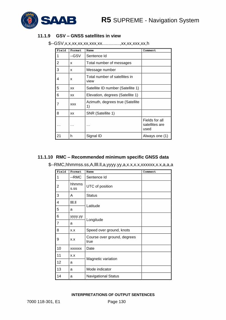
R5 SUPREME - Navigation System
INTERPRETATIONS OF OUTPUT SENTENCES
7000 118-301, E1 Page 130
11.1.9 GSV – GNSS satellites in view
$--GSV,x,x,xx,xx,xx,xxx,xx..............,xx,xx,xxx,xx,h
Field Format Name Comment
1 --GSV Sentence Id
2 x Total number of messages
3 x Message number
4 x Total number of satellites in view
5 xx Satellite ID number (Satellite 1)
6 xx Elevation, degrees (Satellite 1)
7 xxx Azimuth, degrees true (Satellite 1)
8 xx SNR (Satellite 1)
… … … Fields for all satellites are used
21 h Signal ID Always one (1)
11.1.10 RMC – Recommended minimum specific GNSS data
$--RMC,hhmmss.ss,A,llll.ll,a,yyyy.yy,a,x.x,x.x,xxxxxx,x.x,a,a,a
Field Format Name Comment
1 --RMC Sentence Id
2 hhmmss.ss
UTC of position
3 A Status
4 llll.ll Latitude
5 a
6 yyyy.yy Longitude
7 a
8 x.x Speed over ground, knots
9 x.x Course over ground, degrees true
10 xxxxxx Date
11 x.x Magnetic variation
12 a
13 a Mode indicator
14 a Navigational Status

R5 SUPREME - Navigation System
INTERPRETATIONS OF OUTPUT SENTENCES
7000 118-301, E1 Page 131
11.1.11 VTG – Course over ground and ground speed
$--VTG,x.x,T,x.x,M,x.x,N,x.x,K,a
Field Format Name Comment
1 --VTG Sentence Id
2 x.x Course over ground, degrees true
3 T
4 x.x Course over ground, degrees magnetic
5 M
6 x.x Speed over ground, knots
7 N
8 x.x Speed over ground, km/h
9 K
10 a Mode indicator
11.1.12 ZDA – Time and date
$--ZDA,hhmmss.ss,xx,xx,xxxx,xx,xx
Field Format Name Comment
1 --ZDA Sentence Id
2 hhmmss.ss
UTC
3 xx Day (UTC)
4 xx Month (UTC)
5 xxxx Year (UTC)
6 xx Local zone hours Used if configured
7 xx Local zone minutes Used if configured

R5 SUPREME - Navigation System
INTERPRETATIONS OF OUTPUT SENTENCES
7000 118-301, E1 Page 132
11.2 Output Sentences, Navigation
All output sentences use GP as talker identifier.
11.2.1 ALR – Alarm State
$--ALR,hhmmss.ss,xxx,A,A,c--c
Field Format Name Comment
1 --ALR Sentence Id
2 hhmmss.ss
UTC time of last condition change
3 xxx Alarm identifier number
4 A Alarm condition A = Threshold exceeded, V = not exceeded
5 A Acknowledge state
A = Acknowledged, V = Unacknowledged
6 c--c Alarm description text
11.2.2 AAM – Waypoint arrival alarm
$--AAM,A,A,x.x,N,c--c
Field Format Name Comment
1 --AAM Sentence Id
2 A Status
3 A Status
4 x.x Arrival circle radius
5 N Units of radius, nautical miles
6 c--c Waypoint ID

R5 SUPREME - Navigation System
INTERPRETATIONS OF OUTPUT SENTENCES
7000 118-301, E1 Page 133
11.2.3 APB – Heading/Track Controller (Autopilot) Sentence B
$--APB,A,A,x.x,a,N,A,A,x.x,a,c--c,x.x,a,x.x,a,a
Field Format Name Comment
1 --APB Sentence Id
2 A Status
3 A Status
4 x.x Magnitude of XTE
5 a Direction to Steer
6 N XTE units
7 A Status
8 A Status
9 x.x Bearing origin to destination
10 a
11 c--c Destination waypoint ID
12 x.x Bearing, present position to destination
13 a
14 x.x Heading to steer to destination
15 a
16 a Mode indicator
11.2.4 BOD – Bearing, origin to destination
$--BOD,x.x,T,x.x,M,c--c,c--c
Field Format Name Comment
1 --BOD Sentence Id
2 x.x Bearing, degrees true
3 T
4 x.x Bearing, degrees magnetic
5 M
6 c--c Destination waypoint ID
7 c--c Origin waypoint ID
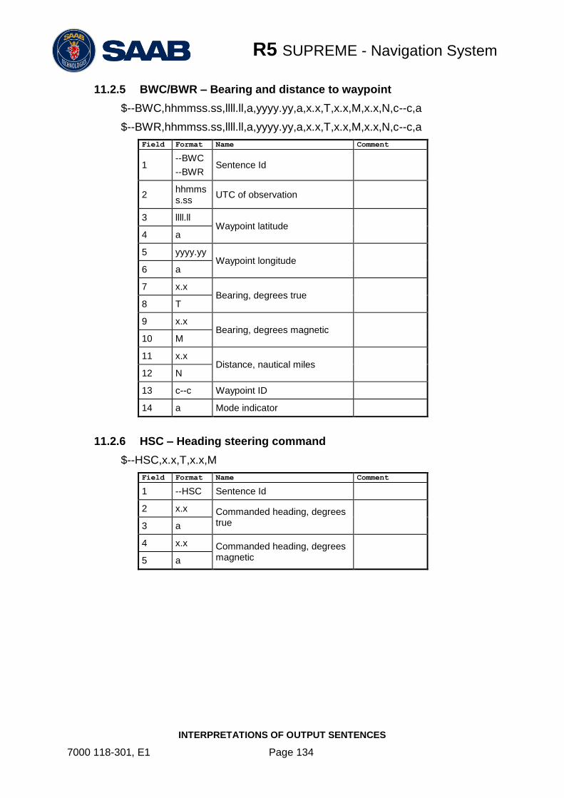
R5 SUPREME - Navigation System
INTERPRETATIONS OF OUTPUT SENTENCES
7000 118-301, E1 Page 134
11.2.5 BWC/BWR – Bearing and distance to waypoint
$--BWC,hhmmss.ss,llll.ll,a,yyyy.yy,a,x.x,T,x.x,M,x.x,N,c--c,a
$--BWR,hhmmss.ss,llll.ll,a,yyyy.yy,a,x.x,T,x.x,M,x.x,N,c--c,a
Field Format Name Comment
1 --BWC
--BWR Sentence Id
2 hhmmss.ss
UTC of observation
3 llll.ll Waypoint latitude
4 a
5 yyyy.yy Waypoint longitude
6 a
7 x.x Bearing, degrees true
8 T
9 x.x Bearing, degrees magnetic
10 M
11 x.x Distance, nautical miles
12 N
13 c--c Waypoint ID
14 a Mode indicator
11.2.6 HSC – Heading steering command
$--HSC,x.x,T,x.x,M
Field Format Name Comment
1 --HSC Sentence Id
2 x.x Commanded heading, degrees true
3 a
4 x.x Commanded heading, degrees magnetic
5 a

R5 SUPREME - Navigation System
INTERPRETATIONS OF OUTPUT SENTENCES
7000 118-301, E1 Page 135
11.2.7 RMB – Recommended minimum navigation information
$--RMB,A,x.x,a,c--c,c--c,llll.ll,a,yyyy.yy,a,x.x,x.x,x.x,A,a
Field Format Name Comment
1 --RMB Sentence Id
2 A Status
3 x.x Cross track error, nautical miles
4 a Direction to steer L/R
5 c--c Origin waypoint ID
6 c--c Destination waypoint ID
7 llll.ll Destination waypoint latitude
8 a
9 yyyy.yy Destination waypoint longitude
10 a
11 x.x Range to destination, nautical miles
12 x.x Bearing to destination, degrees true
13 x.x Destination closing velocity
14 A Arrival status
15 a Mode indicator
11.2.8 RTE – Routes
$--RTE,x.x,x.x,a,c--c,c--c,…,c--c
Field Format Name Comment
1 --RTE Sentence Id
2 x.x Total number of messages being transmitted
3 x.x Message number
4 a Message mode
5 c--c Route identifier
6 c--c Waypoint identifier (first)
… … …
n c--c Waypoint identifier (last)

R5 SUPREME - Navigation System
INTERPRETATIONS OF OUTPUT SENTENCES
7000 118-301, E1 Page 136
11.2.9 WPL – Waypoint location
$--WPL,llll.ll,a,yyyy.yy,a,c--c
Field Format Name Comment
1 --VPL Sentence Id
2 llll.ll Waypoint latitude, N/S
3 a
4 yyyy.yy Waypoint longitude, E/W
5 a
6 c--c Waypoint identifier
11.2.10 XTE – Heading steering command
$--XTE,A,A,x.x,a,N,a
Field Format Name Comment
1 --XTE Sentence Id
2 A Status
3 A Status
4 x.x Magnitude of cross-track error
5 a Direction to steer, L/R
6 N Units, nautical miles
7 a Mode indicator
11.3 Output Sentences, Old NMEA Versions
All output sentences use GP as talker identifier.
11.3.1 Rnn – Routes (old NMEA versions)
Can only be used for output of working (active) route. It is recommended to use the RTE
sentence instead if this sentence.
$--Rnn,cccc,cccc,…,cccc
Field Format Name Comment
1 --Rnn Sentence id and route identifier ‘nn’ is always 00
2 cccc Waypoint identifier (first)
.. … …
15 cccc Waypoint identifier (last)

R5 SUPREME - Navigation System
INTERPRETATIONS OF INPUT SENTENCES
7000 118-301, E1 Page 137
12 INTERPRETATIONS OF INPUT SENTENCES
Per default, any talker identifier is accepted.
12.1 Input Sentences
12.1.1 ACK – Acknowledge alarm
$--ACK,xxx
Field Format Name Comment
1 --ACK Sentence Id Used
2 xxx Alarm identifier number
Corresponds to ALR message for alarm to acknowledge
12.1.2 DBT – Depth below transducer
The displayed depth will be adjusted according to depth input configuration parameters. The used depth (in the correct unit) is calculated from field 2.
$--DPT,x.x,f,x.x,M,x.x,F
Field Format Name Comment
1 --DPT Sentence Id Used
2 x.x Water depth, feet Used
3 f
4 x.x Water depth, meter Not used
5 M
6 x.x Water depth, fathoms Not used
7 F
12.1.3 DPT – Depth
The displayed depth will be adjusted according to depth input configuration parameters.
$--DPT,x.x,x.x,x.x
Field Format Name Comment
1 --DPT Sentence Id Used
2 x.x Water depth relative to transducer, meter
Used
3 x.x Offset from transducer, meter Used if configured
4 x.x Max range scale in use Not used

R5 SUPREME - Navigation System
INTERPRETATIONS OF INPUT SENTENCES
7000 118-301, E1 Page 138
12.1.4 HDG – Heading, Deviation and Variation
$--HDG,x.x,x.x,a,x.x,a
Field Format Name Comment
1 --HDG Sentence Id Used
2 x.x Magnetic sensor heading, degrees
Used
3 x.x Magnetic deviation, degrees E/W
Used 4 a
5 x.x Magnetic variation, degrees E/W
Used 6 a
12.1.5 HDT – Heading, True
$--HDT,x.x,T
Field Format Name Comment
1 --HDG Sentence Id Used
2 x.x Heading, degrees true Used
3 T
12.1.6 RTE – Routes
$--RTE,x.x,x.x,a,c--c,c--c,…,c--c
Field Format Name Comment
1 --RTE Sentence Id Used
2 x.x Total number of messages being transmitted
Used
3 x.x Message number Used
4 a Message mode Used
5 c--c Route identifier Used
6 c--c Waypoint identifier (first) Used
… … … …
n c--c Waypoint identifier (last) Used

R5 SUPREME - Navigation System
INTERPRETATIONS OF INPUT SENTENCES
7000 118-301, E1 Page 139
12.1.1 THS – True Heading and Status
$--THS,x.x,a
Field Format Name Comment
1 --THS Sentence Id Used
2 x.x Heading, degrees true Used if Status is set to ‘A’
3 a Status Used
12.1.2 WPL – Waypoint location
$--WPL,llll.ll,a,yyyy.yy,a,c--c
Field Format Name Comment
1 --WPL Sentence Id Used
2 llll.ll Waypoint latitude, N/S Used
3 a
4 yyyy.yy Waypoint longitude, E/W Used
5 a
6 c--c Waypoint identifier Used
12.1.3 VHW – Water speed and heading
$--VHW,x.x,T,x.x,M,x.x,N,x.x,K
Field Format Name Comment
1 --VHW Sentence Id Used
2 x.x Heading, degrees true Used
3 T
4 x.x Heading, degrees magnetic Used
5 M
6 x.x Speed, knots Used
7 N
8 x.x Speed, km/h Not used
9 K
12.2 Input Sentences, Old NMEA Versions
12.2.1 Rnn – Routes (old NMEA versions)
Can only be used for input of working (active) route. It is recommended to use the RTE
sentence instead if this sentence. Per default, any talker ID is accepted.
$--Rnn,cccc,cccc,…,cccc
Field Format Name Comment

R5 SUPREME - Navigation System
INTERPRETATIONS OF INPUT SENTENCES
7000 118-301, E1 Page 140
1 --Rnn Sentence id and route identifier
‘nn’ is interpreted as route identifier (00 – 99).
2 cccc Waypoint identifier (first) Used
.. … … …
15 cccc Waypoint identifier (last) Used

R5 SUPREME - Navigation System
ALTERNATE SYSTEM SETUPS
7000 118-301, E1 Page 141
13 ALTERNATE SYSTEM SETUPS
13.1 Redundant Navigation Systems
R4 GPS Navigation Sensor orR4 DGPS Navigation Sensor
Front Hatch
USB Host
SDHC Card Reader
Pilot Plug (Used in AIS and
Combined System only)
USER 1
In/Out
USER 2
Out
USER 3
In/Out
USER 4
In/Out
Speed
Log
Out
4xDigital
I/O
Alarm Ack
In
AlarmRelay
CAT5 Ethernet
R5 NAV Sensor Cable
External power 24 VDC
R5 Signal Cable
R5 Power Cable
R4 GPS Navigation Sensor orR4 DGPS Navigation Sensor
Front Hatch
USB Host
SDHC Card Reader
Pilot Plug (Used in AIS and
Combined System only)
USER 1
In/Out
USER 2
Out
USER 3
In/Out
USER 4
In/Out
Speed
Log
Out
4xDigital
I/O
Alarm Ack
In
AlarmRelay
R5 NAV Sensor Cable
External power 24 VDC
R5 Signal Cable
R5 Power Cable
Figure 108 – Redundant NAV interconnection
13.2 Navigation System with Slave Displays
MASTER CDUSlave CDU
Slave CDU
Slave CDU
R4 GPS Navigation Sensor orR4 DGPS Navigation Sensor
USER 1
In/Out
USER 2
Out
USER 3
In/Out
USER 4
In/Out
Speed
Log
Out
4xDigital
I/O
Alarm Ack
In
AlarmRelay
CAT5 Ethernet
R5 NAV Sensor Cable
External power 24 VDC
24 VDC/2A External fuse
R5 Power Cable
CAT5 Ethernet
CAT5 Ethernet
R5 Signal Cable
R5 Power Cable
24 VDC/2A External fuse
R5 Power Cable
24 VDC/2A External fuse
R5 Power Cable
IEC 60945 Ethernet Switch
Figure 109 – Slave display interconnection

R5 SUPREME - Navigation System
ALTERNATE SYSTEM SETUPS
7000 118-301, E1 Page 142
13.3 Combined AIS and Navigation system setup
Below details how to install a combined AIS and Navigation system, using one CDU.
The CDU can act as both AIS MKD and Navigation system at the same time. The initial system setup wizard will activate the correct dialogs and menus.
Running the CDU in this mode will activate many more functions and views in the system, not detailed in this manual. For information about AIS functions and setup, please see the navigation system manual:
7000 118-300, R5 SUPREME AIS System manual.
As with a standard R5 Navigation System installation, the R5 NAV Junction box can be omitted if open cables for the CDU and Navigation sensor are used together with a customer own solution for interconnection of the system.
In addition to the standard R5 NAV parts, the following are needed in addition:
Name Part number Qty.
R5 SUPREME Transponder
7000 118-100 incl. AIS SW 1.0.X
7000 118-501 1
R5 Power Cable 2m 7000 118-077 1
R5 Signal Cable DSUB-DSUB 2m 7000 118-286 2
R5 AIS Junction box 7000 118-120 1
R5 SUPREME Ethernet Cable 5m.
or equivalent.
7000 000-525 1
Printed document set
Including:
AIS Installation Short Instruction
AIS Operators Short Instruction
AIS Certificate set
7000 118-370
7000 118-363
7000 118-364
7000 118-365
1
Transponder GPS antenna
MA-700 or
AT575-68 or
Combined VHF/GPS Antenna AC Marine
7000 000-485
7000 000-135
7000 000-435
1
AIS VHF Antenna
BA1012 or equivalant
7000 000-077
1

R5 SUPREME - Navigation System
ALTERNATE SYSTEM SETUPS
7000 118-301, E1 Page 143
13.3.1 R5 Combined with R5 NAV Junction box
R4 Navigation Sensor
R5 NAV Junction Box
R5 NAV Junction Box
R5 NAV Sensor Cable
External power 24 VDC
R5 Signal Cable
R5 Power Cable
R5 AIS Junction Box
Ethernet
External power 12-24 VDC
R5 Transponder
R5 Signal CableR5 Signal Cable
R5 Power Cable
VHF
GPS(D)GNSS
R5 CDU in Combined AIS and NAV mode
Figure 110- Combined AIS and Navigation system with R5 NAV junction box
13.3.1 R5 Combined without R5 NAV Junction box
VHF
System
Port
User
Port 1
User
Port 2
Speed
Log
Alarm
Output
RS-422 Ports
User
Port 3
User
Port 4
R4
SensorAlarm
ACK
Binary PortsRS-422 Ports
R4 Nav Signal and Power Cable
R4 Navigation Sensor
24 VDC/1A
External fuse
24 VDC/5A
External fuse
Front Hatch
USB Host
SDHC Card Reader
Pilot Plug (Used in AIS and
Combined System only)
R5 Signal Cable DSUB-OPEN
R5 Power Cable
R5 AIS Junction Box
Ethernet
External power 24 VDC
R5 Transponder
R5 Signal CableR5 Signal Cable
R5 Power Cable
GPS(D)GNSS
R5 CDU in Combined AIS and NAV mode
Figure 111- Combined AIS and Navigation system without R5 NAV junction box

R5 SUPREME - Navigation System
ELECTRICAL INTERFACES
7000 118-301, E1 Page 144
14 ELECTRICAL INTERFACES
14.1 CDU Interfaces:
14.1.1 CDU back:
14.1.1.1 Ethernet port – RJ-45 100 MBit – IEC 61162-450
14.1.1.2 I/O port
Pin In/Out Signal Name Signal Type R5 Signal Cable
DSUB-OPEN
1 Out Sensor Port – TxB (+) RS422 White
2 Out Sensor Port – TxA (-) RS422 Brown
3 In User Port 4 – RxB (+) RS422 Green
4 In User Port 4 – RxA (-) RS422 Yellow
5 Out User Port 4 – TxB (+) RS422 Grey
6 Out User Port 4 – TxA (-) RS422 Pink
7 In User Port 3 – RxB (+) RS422 Blue
8 In User Port 3 – RxA (-) RS422 Red
9 - User Port 3 – GND RS422 Black
10 - Sensor Port – GND RS422 Violet
11 In Sensor Port – RxB (+) RS422 Grey / Pink
12 In Sensor Port – RxA (-) RS422 Red / Blue
13 - User Port 4 – GND RS422 White / Green
14 Out General I/O 1 – Out Binary Brown / Green
15 Out General I/O 0 – Out Binary White / Yellow
16 In General I/O 1 – In Binary Yellow / Brown
17 Out User Port 3 – TxB (+) RS422 White / Grey
18 Out User Port 3 – TxA (-) RS422 Grey / Brown
19 In General I/O 2 – In Binary White / Pink

R5 SUPREME - Navigation System
ELECTRICAL INTERFACES
7000 118-301, E1 Page 145
Pin In/Out Signal Name Signal Type R5 Signal Cable
DSUB-OPEN
20 - GND Binary Pink / Brown
21 - GND Binary White / Blue
22 In General I/O 0 – In Binary Brown / Blue
23 Out General I/O 3 - Out Binary White / Red
24 - NOT CONNECTED - Brown / Red
25 - NOT CONNECTED -
26 - NOT CONNECTED -
Table 11 – 26-pin High Density D-sub
14.1.1.3 Power port
Pin In/Out Signal Name Signal Type R5 Power Cable
1 In PWR + 24 VDC Red
2 In PWG GND 0 VDC Black
3 - - - Brown
4 - - - Orange
Table 12 – CDU Power port
14.1.1.4 GND Screw – M6
14.1.2 CDU Front hatch:
Figure 112- CDU Front ports
14.1.2.1 USB Host Type A
USB 2.0.
Supports FAT32 file systems and USB keyboards
14.1.2.2 CDU Pilot Plug RS-422
Only active in AIS or Combined AIS / Nav installations.
This bi-directional port is routed over Ethernet to the Transponder.

R5 SUPREME - Navigation System
ELECTRICAL INTERFACES
7000 118-301, E1 Page 146
Figure 113 - CDU Pilot plug pin numbering
Pilot plug Signal Type
PIN 9 RS-422 GND
PIN 1 RS-422 TX-A
PIN 5 RS-422 RX-A
PIN 4 RS-422 TX-B
PIN 6 RS-422 RX-B
Table 13 – CDU Pilot port signals
14.1.2.3 Secure Digital Card Reader
Supports SD and SDHC cards with FAT32 file systems.

R5 SUPREME - Navigation System
ELECTRICAL INTERFACES
7000 118-301, E1 Page 147
14.1.3 Electrical Characteristics of CDU Serial ports
The serial ports in the R5 SUPREME CDU are the Sensor Port, User Port 3 and user Port 4.
14.1.3.1 Output Drive Capacity
Each serial port transmitter in the R5 SUPREME CDU can have a maximum of 25 listeners drawing 2.0 mA each.
14.1.3.2 Input Load
Input impedance for each listener input is 6.4 kΩ.
14.1.3.3 Termination
The R5 NAV Junction Box has built in termination resistors. If needed, the termination resistors can be connected by flipping the respective termination switch in the junction box. If the junction box is not used, a 1kΩ termination resistor can be used close to the receiver end.
14.1.3.4 Schematics
Each of the RS422 serial interfaces on the R5 SUPREME CDU fulfils the requirements of IEC 61162-2. All serial ports on the R5 SUPREME CDU support communication rates up to 115200 bps.
A detailed schematic of the serial ports in the R5 SUPREME CDU is shown in Figure 114.
Figure 114 – R5 SUPREME CDU Serial Port Schematics
Internal signals to/from R5 SUPREME CDU
To/from external equipment

R5 SUPREME - Navigation System
ELECTRICAL INTERFACES
7000 118-301, E1 Page 148
14.2 R4 Navigation Sensor interfaces
14.2.1 Signal and Power port
Connector: 18-pin circular ConXall female
Signal types:
Pin In/Out Signal Name Signal Type R4 Sensor
Signal and
Power Cable
Colour 1 Out User Port 1– RxA (-) RS422 / RTCM SC-104
White
2 In System Port – RxA(-) RS422 Green
3 In User Port 1– RxB (+) RS422 / RTCM SC-104
Brown
4 Out Alarm Ack GND 0 VDC Brown/Green
5 In System Port – RxB(+) RS422 Yellow
6 Out Speed Log GND 0 VDC Yellow/Brown
7 Out User Port 1– TxA (-) RS422 Grey
8 Out User Port 1– TxB (+) RS422 Pink
9 In Power GND 0 VDC Blue
10 Out System Port – TxA(-) RS422 Black
11 Out System Port – TxB(+) RS422 Purple
12 - NC - NC
13 Out User Port 2 – TxB (+) RS422 / RTCM SC-104
Red/Blue
14 In Alarm Ack In 0 VDC / NC White/Green
15 Out Speed Log Out 0 VDC / 5VDC White/Yellow
16 Out User Port 2 – TxA (-) RS422 / RTCM SC-104
Grey/Pink
17 In Power+ ( Vcc) 12-24 VDC Red
18 Out Alarm Relay Out 0 V (Active) Vcc – 1V (Inactive)
White/Grey
14.2.2 Antenna connector
Connector: TNC (Female)
Output: +5 VDC (referenced to VCC input GND)
14.2.3 Electrical Characteristics of R4 Navigation Sensor serial ports
The serial ports in the R4 Navigation Sensor are the System Port, User Port 1 and User Port 2.
14.2.3.1 Output Drive Capacity
Each talker output can have a maximum of 10 listeners drawing 2.0 mA.

R5 SUPREME - Navigation System
ELECTRICAL INTERFACES
7000 118-301, E1 Page 149
14.2.3.2 Input Load
Each listener draws less than 2 mA @ 2 V input voltage.
14.2.3.3 Termination
The R5 NAV Junction Box has built in termination resistors. If needed, the termination resistors can be connected by flipping the respective termination switch in the junction box. If the junction box is not used, a 1kΩ termination resistor can be used close to the receiver end.
14.2.3.4 Schematics
Each of the RS-422 serial interfaces on the R4 Navigation Sensor fulfils the requirements as specified in IEC 61162-1. In addition, User Port 1 supports a communication rate up to 38400 bps and User Port 2 up to 19200 bps.
Figure 115 - R4 Navigation Sensor Serial Interface Input Schematics
Figure 116 - R4 Navigation Sensor Serial Onterface Output Schematics

R5 SUPREME - Navigation System
ELECTRICAL INTERFACES
7000 118-301, E1 Page 150
14.2.4 Electrical Characteristics of R4 Navigation Sensor digital ports
14.2.4.1 Speed Log Out Port
The Speed Log Out port provides a 50 ms long 5 V pulse with an interval corresponding to the ship’s present speed, and system configuration.
The speed pulse interval has a resolution of 50 ms, providing a resolution of 0.5 knots up to 10-20 knots depending on pulse rate and a working range up to 30 knots.
The port has a driving capacity of 10 mA.
Note: Signal GND is internally connected to the negative power supply of the R4 Navigation Sensor.
14.2.4.2 Alarm Acknowledge Binary Port
The “Alarm Ack In” wire should be connected to Alarm Ack GND via a normally open momentary switch, capable of handling a 1 mA current
Note: Alarm Ack GND is internally connected to the negative power supply of the R4 Navigation Sensor.
14.2.4.3 Alarm Out Binary Port
Connects to an external alarm relay, voltages are referenced to system Power GND.
The port has a driving capacity of 50 mA and a minimum load resistance of 460 Ω.
Alarm Active: 0 VDC
No Alarm active: 23 VDC ( when sensor external power is 24VDC)
11 VDC ( when sensor external power is 12VDC)

R5 SUPREME - Navigation System
ELECTRICAL INTERFACES
7000 118-301, E1 Page 151
14.3 R5 NAV Junction box Interfaces
14.3.1 External ports:
14.3.1.1.1 26 pin DSUB Female port:
Connects by R5 Signal Cable DSUB-DSUB to R5 CDU “I/O”
14.3.1.1.2 26 pin DSUB Male port:
Connects by R5 NAV Sensor Cable to R4 Navigation Sensor power and data interface port
14.3.1.1.3 Cable gland ports:
M20: Will fit 6-12 mm cables. For larger cables please unscrew the cable gland.
14.3.2 External Power:
The R5 SUPREME Navigation System is designed to operate on 12-24 volts DC.
The R5 NAV Junction Box shall be connected to an emergency power source. If connected to an emergency battery, a re-calculation must be made for the battery capacity.
To avoid power and voltage drops in the feed line it is important that sufficient size of cable is used.
Note: The R5 NAV Junction Box has one 1A fuse for the R4 Navigation Sensor and on 5A fuse for the R5 SUPREME CDU

R5 SUPREME - Navigation System
ELECTRICAL INTERFACES
7000 118-301, E1 Page 152
14.3.3 Internal circuit board layout:
For detailed description of routed signals, see R5 CDU and R4 Nav sensor interface specifications.
Figure 117 Circuit Board Layout
Item1 Terminal Marking Description
P5 POWER IN Terminal block for External 12-24VDC Input Power
P8 CAN BUS Terminal block for CAN Bus
P5 CDU POWER Terminal block for R5 CDU Power
P19 USER 4 Terminal block for User 4 RS422 Port
P18 USER 3 Terminal block for User 3 RS422 Port
P2 USER 2 Terminal block for User 2 RS422 Port
P12 USER 1 Terminal block for User 1 RS422 Port
P10 SPEED LOG / ALARM ACK
Terminal block for Speed Log Output and Alarm Acknowledge Input
P9 GPIO OUT Terminal block for GPIO Out
P7 GPIO IN Terminal block for GPIO In
P6 ALARM RELAY Terminal block for NAV Alarm Relay
SW1 - Termination Switches for User 4, 3 and 1
P3 - D-SUB Connector for R5 Supreme CDU

R5 SUPREME - Navigation System
ELECTRICAL INTERFACES
7000 118-301, E1 Page 153
P4 - D-SUB Connector for R4 Navigation Sensor
F1 - 5A fuse for CDU
F2 - 1A fuse for Navigation Sensor
Table 1 – Terminals and Components
Note 1: The item markings listed in Column 1 are not visible on the circuit board. The terminal markings should be used when referring to terminals.

R5 SUPREME - Navigation System
MECHANICAL DRAWINGS
7000 118-301, E1 Page 154
15 MECHANICAL DRAWINGS
15.1 CDU Physical Size and Mechanical Drawing
Figure 118 – R5 SUPREME CDU Mechanical Drawing (mm)

R5 SUPREME - Navigation System
MECHANICAL DRAWINGS
7000 118-301, E1 Page 155
15.2 CDU Panel Mount Cutout Hole dimensions

R5 SUPREME - Navigation System
MECHANICAL DRAWINGS
7000 118-301, E1 Page 156
15.3 CDU Mounting Frame cutout and dimensions
Figure 119 – R5 SUPREME CDU, Mounting frame dimensions
Figure 120 – R5 SUPREME CDU, Cutout Measurements for Panel Flush Mount (mm)

R5 SUPREME - Navigation System
MECHANICAL DRAWINGS
7000 118-301, E1 Page 157
15.4 Sensor Physical Size and Mechanical Drawing
Figure 121 – R4 Navigation Sensor Measurements (mm)

R5 SUPREME - Navigation System
MECHANICAL DRAWINGS
7000 118-301, E1 Page 158
15.5 R5 NAV Junction Box Physical Size and Mechanical Drawing
Figure 122 – R5 NAV Junction Box, Dimensions (mm)
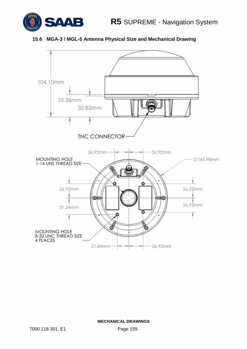
R5 SUPREME - Navigation System
MECHANICAL DRAWINGS
7000 118-301, E1 Page 159
15.6 MGA-3 / MGL-5 Antenna Physical Size and Mechanical Drawing

R5 SUPREME - Navigation System
GLOSSARY
7000 118-301, E1 Page 160
16 GLOSSARY
ACK Acknowledgement
AFSK Audio Frequency Shift Keying
AIS Automatic Identification System
Ant Antenna
App Application
ARPA Automatic Radar Plotting Aid
BRG Bearing
BS Base Station
CDU Control and Display Unit
Ch Channel
COG Course Over Ground
Comm Communication
DGNSS Differential Global Navigational Satellite System
Disp Display
DOP Dilution Of Precision
DTE Data Terminal Equipment
DSC Digital Selective Calling
ECDIS Electronic Chart Display and Information System
EGNOS European Geostationary Navigation Overlay Service
EPFS Electronic Position Fixing System
ETA Estimated Time of Arrival
Ext External
GALILEO European GNSS
GLONASS Russian GNSS
GMSK Gaussian Minimum Shift Keying
GNSS Global Navigational Satellite System
GPS Global Positioning System
HDG Heading
HDOP Horizontal Dilution Of Precision
H/W Hardware
IALA International Association of Lighthouse Authorities
ID Identifier
IEC International Electrotechnical Commission
IMO International Maritime Organization
Int Internal
IP Internet Protocol (adress)
ITU International Telecommunications Union

R5 SUPREME - Navigation System
GLOSSARY
7000 118-301, E1 Page 161
LAT Latitude
LED Light Emitting Diode
LOC Local
LON Longitude
LWE Light Weight Ethernet
Msg Message
MKD Minimum Keyboard and Display
MSAS MTSAT Satellite Augmentation System (Japan)
NMEA National Marine Electronics Association
MMSI Maritime Mobile Service Identity
N/A Not available
NE North East
NVM Non-Volatile Memory
Pos Position
RAIM Receiver Autonomous Integrity Monitoring
RNG Range
RATDMA Random Access Time Division Multiple Access
ROT Rate Of Turn
RTA Recommended Time of Arrival
Rx Receive
SAR Search And Rescue
SART Search And Rescue Transmitter
SBAS Satellite Based Augmentation System
SNR Signal to Noise Ratio
SOG Speed Over Ground
SRM Safety Related Message
Sync Synchronization
SW South West
S/W Software
UTC Universal Time Coordinated
VDOP Vertical Dilution Of Precision
WAAS Wide Area Augmentation System (United States)

R5 SUPREME - Navigation System
APPENDIX B - LICENSE
7000 118-301, E1 Page 162
17 APPENDIX B - LICENSE
The R5 SUPREME CDU runs on a Linux operating system which is licensed with GNU General Public License. The source code of the linux kernel can be obtained by contacting Saab TransponderTech AB:
Saab TransponderTech Låsblecksgatan 3 589 31 Linköping Sweden
Email: [email protected]
17.1 Copy of the GNU General Public License
GNU GENERAL PUBLIC LICENSE
Version 2, June 1991
Copyright (C) 1989, 1991 Free Software Foundation, Inc. 51 Franklin St, Fifth Floor, Boston, MA 02110-1301 USA
Everyone is permitted to copy and distribute verbatim copies of this license document, but changing it is not allowed.
Preamble
The licenses for most software are designed to take away your freedom to share and change it. By contrast, the GNU General Public License is intended to guarantee your freedom to share and change free software--to make sure the software is free for all its users. This General Public License applies to most of the Free Software Foundation's software and to any other program whose authors commit to using it. (Some other Free Software Foundation software is covered by the GNU Library General Public License instead.) You can apply it to your programs, too.
When we speak of free software, we are referring to freedom, not price. Our General Public Licenses are designed to make sure that you have the freedom to distribute copies of free software (and charge for this service if you wish), that you receive source code or can get it if you want it, that you can change the software or use pieces of it in new free programs; and that you know you can do these things.
To protect your rights, we need to make restrictions that forbid anyone to deny you these rights or to ask you to surrender the rights. These restrictions translate to certain responsibilities for you if you distribute copies of the software, or if you modify it.
For example, if you distribute copies of such a program, whether gratis or for a fee, you must give the recipients all the rights that you have. You must make sure that they, too, receive or can get the source code. And you must show them these terms so they know their rights.
We protect your rights with two steps: (1) copyright the software, and (2) offer you this license which gives you legal permission to copy, distribute and/or modify the software.
Also, for each author's protection and ours, we want to make certain that everyone understands that there is no warranty for this free software. If the software is modified by someone else and passed on, we want its recipients to know that what they have is not the original, so that any problems introduced by others will not reflect on the original authors' reputations.
Finally, any free program is threatened constantly by software patents. We wish to avoid the danger that redistributors of a free program will individually obtain patent licenses, in effect making the program proprietary. To prevent this, we have made it clear that any patent must be licensed for everyone's free use or not licensed at all.
The precise terms and conditions for copying, distribution and modification follow.
GNU GENERAL PUBLIC LICENSE
TERMS AND CONDITIONS FOR COPYING, DISTRIBUTION AND MODIFICATION
0. This License applies to any program or other work which contains a notice placed by the copyright holder saying it may be distributed under the terms of this General Public License. The "Program", below, refers to any such program or work, and a "work based on the Program" means either the Program or any derivative work under copyright law: that is to say, a work containing the Program or a portion of it, either verbatim or with modifications and/or translated into another language. (Hereinafter, translation is included without limitation in the term "modification".) Each licensee is addressed as "you".
Activities other than copying, distribution and modification are not covered by this License; they are outside its scope. The act of running the Program is not restricted, and the output from the Program is covered only if its contents constitute a work based on the Program (independent of having been made by running the Program). Whether that is true depends on what the Program does.
1. You may copy and distribute verbatim copies of the Program's source code as you receive it, in any medium, provided that you conspicuously and appropriately publish on each copy an appropriate copyright notice and disclaimer of warranty; keep intact all the notices that refer to this License and to the absence of any warranty; and give any other recipients of the Program a copy of this License along with the Program.
You may charge a fee for the physical act of transferring a copy, and you may at your option offer warranty protection in exchange for a fee.
2. You may modify your copy or copies of the Program or any portion of it, thus forming a work based on the Program, and copy and distribute such modifications or work under the terms of Section 1 above, provided that you also meet all of these conditions:
i. You must cause the modified files to carry prominent notices stating that you changed the files and the date of any change.
ii. You must cause any work that you distribute or publish, that in whole or in part contains or is derived from the Program or any part thereof, to be licensed as a whole at no charge to all third parties under the terms of this License.
iii. If the modified program normally reads commands interactively when run, you must cause it, when started running for such interactive use in the most ordinary way, to print or display an announcement including an appropriate copyright notice and a notice that there is no warranty (or else, saying that you provide a warranty) and that users may redistribute the program under these conditions, and telling the user how to view a copy of this License. (Exception: if the Program itself is interactive but does not normally print such an announcement, your work based on the Program is not required to print an announcement.)
These requirements apply to the modified work as a whole. If identifiable sections of that work are not derived from the Program, and can be reasonably considered independent and separate works in themselves, then this License, and its terms, do not apply to those sections when you distribute them as separate works. But when you distribute the same sections as part of a whole which is a work based on the Program, the distribution of the whole must be on the terms of this License, whose permissions for other licensees extend to the entire whole, and thus to each and every part regardless of who wrote it.
Thus, it is not the intent of this section to claim rights or contest your rights to work written entirely by you; rather, the intent is to exercise the right to control the distribution of derivative or collective works based on the Program.

R5 SUPREME - Navigation System
APPENDIX B - LICENSE
7000 118-301, E1 Page 163
In addition, mere aggregation of another work not based on the Program with the Program (or with a work based on the Program) on a volume of a storage or distribution medium does not bring the other work under the scope of this License.
3. You may copy and distribute the Program (or a work based on it, under Section 2) in object code or executable form under the terms of Sections 1 and 2 above provided that you also do one of the following:
a) Accompany it with the complete corresponding machine-readable source code, which must be distributed under the terms of Sections 1 and 2 above on a medium customarily used for software interchange; or,
b) Accompany it with a written offer, valid for at least three years, to give any third party, for a charge no more than your cost of physically performing source distribution, a complete machine-readable copy of the corresponding source code, to be distributed under the terms of Sections 1 and 2 above on a medium customarily used for software interchange; or,
c) Accompany it with the information you received as to the offer to distribute corresponding source code. (This alternative is allowed only for noncommercial distribution and only if you received the program in object code or executable form with such an offer, in accord with Subsection b above.)
The source code for a work means the preferred form of the work for making modifications to it. For an executable work, complete source code means all the source code for all modules it contains, plus any associated interface definition files, plus the scripts used to control compilation and installation of the executable. However, as a special exception, the source code distributed need not include anything that is normally distributed (in either source or binary form) with the major components (compiler, kernel, and so on) of the operating system on which the executable runs, unless that component itself accompanies the executable.
If distribution of executable or object code is made by offering access to copy from a designated place, then offering equivalent access to copy the source code from the same place counts as distribution of the source code, even though third parties are not compelled to copy the source along with the object code.
4. You may not copy, modify, sublicense, or distribute the Program except as expressly provided under this License. Any attempt otherwise to copy, modify, sublicense or distribute the Program is void, and will automatically terminate your rights under this License. However, parties who have received copies, or rights, from you under this License will not have their licenses terminated so long as such parties remain in full compliance.
5. You are not required to accept this License, since you have not signed it. However, nothing else grants you permission to modify or distribute the Program or its derivative works. These actions are prohibited by law if you do not accept this License. Therefore, by modifying or distributing the Program (or any work based on the Program), you indicate your acceptance of this License to do so, and all its terms and conditions for copying, distributing or modifying the Program or works based on it.
6. Each time you redistribute the Program (or any work based on the Program), the recipient automatically receives a license from the original licensor to copy, distribute or modify the Program subject to these terms and conditions. You may not impose any further restrictions on the recipients' exercise of the rights granted herein. You are not responsible for enforcing compliance by third parties to this License.
7. If, as a consequence of a court judgment or allegation of patent infringement or for any other reason (not limited to patent issues), conditions are imposed on you (whether by court order, agreement or otherwise) that contradict the conditions of this License, they do not excuse you from the conditions of this License. If you cannot distribute so as to satisfy simultaneously your obligations under this License and any other pertinent obligations, then as a consequence you may not distribute the Program at all. For example, if a patent license would not permit royalty-free redistribution of the Program by all those who receive copies directly or indirectly through you, then the only way you could satisfy both it and this License would be to refrain entirely from distribution of the Program.
If any portion of this section is held invalid or unenforceable under any particular circumstance, the balance of the section is intended to apply and the section as a whole is intended to apply in other circumstances.
It is not the purpose of this section to induce you to infringe any patents or other property right claims or to contest validity of any such claims; this section has the sole purpose of protecting the integrity of the free software distribution system, which is implemented by public license practices. Many people have made generous contributions to the wide range of software distributed through that system in reliance on consistent application of that system; it is up to the author/donor to decide if he or she is willing to distribute software through any other system and a licensee cannot impose that choice.
This section is intended to make thoroughly clear what is believed to be a consequence of the rest of this License.
8. If the distribution and/or use of the Program is restricted in certain countries either by patents or by copyrighted interfaces, the original copyright holder who places the Program under this License may add an explicit geographical distribution limitation excluding those countries, so that distribution is permitted only in or among countries not thus excluded. In such case, this License incorporates the limitation as if written in the body of this License.
9. The Free Software Foundation may publish revised and/or new versions of the General Public License from time to time. Such new versions will be similar in spirit to the present version, but may differ in detail to address new problems or concerns.
Each version is given a distinguishing version number. If the Program specifies a version number of this License which applies to it and "any later version", you have the option of following the terms and conditions either of that version or of any later version published by the Free Software Foundation. If the Program does not specify a version number of this License, you may choose any version ever published by the Free Software Foundation.
10. If you wish to incorporate parts of the Program into other free programs whose distribution conditions are different, write to the author to ask for permission. For software which is copyrighted by the Free Software Foundation, write to the Free Software Foundation; we sometimes make exceptions for this. Our decision will be guided by the two goals of preserving the free status of all derivatives of our free software and of promoting the sharing and reuse of software generally.
NO WARRANTY
11. BECAUSE THE PROGRAM IS LICENSED FREE OF CHARGE, THERE IS NO WARRANTY FOR THE PROGRAM, TO THE EXTENT PERMITTED BY APPLICABLE LAW. EXCEPT WHEN OTHERWISE STATED IN WRITING THE COPYRIGHT HOLDERS AND/OR OTHER PARTIES PROVIDE THE PROGRAM "AS IS" WITHOUT WARRANTY OF ANY KIND, EITHER EXPRESSED OR IMPLIED, INCLUDING, BUT NOT LIMITED TO, THE IMPLIED WARRANTIES OF MERCHANTABILITY AND FITNESS FOR A PARTICULAR PURPOSE. THE ENTIRE RISK AS TO THE QUALITY AND PERFORMANCE OF THE PROGRAM IS WITH YOU. SHOULD THE PROGRAM PROVE DEFECTIVE, YOU ASSUME THE COST OF ALL NECESSARY SERVICING, REPAIR OR CORRECTION.
12. IN NO EVENT UNLESS REQUIRED BY APPLICABLE LAW OR AGREED TO IN WRITING WILL ANY COPYRIGHT HOLDER, OR ANY OTHER PARTY WHO MAY MODIFY AND/OR REDISTRIBUTE THE PROGRAM AS PERMITTED ABOVE, BE LIABLE TO YOU FOR DAMAGES, INCLUDING ANY GENERAL, SPECIAL, INCIDENTAL OR CONSEQUENTIAL DAMAGES ARISING OUT OF THE USE OR INABILITY TO USE THE PROGRAM (INCLUDING BUT NOT LIMITED TO LOSS OF DATA OR DATA BEING RENDERED INACCURATE OR LOSSES SUSTAINED BY YOU OR THIRD PARTIES OR A FAILURE OF THE PROGRAM TO OPERATE WITH ANY OTHER PROGRAMS), EVEN IF SUCH HOLDER OR OTHER PARTY HAS BEEN ADVISED OF THE POSSIBILITY OF SUCH DAMAGES.
END OF TERMS AND CONDITIONS
How to Apply These Terms to Your New Programs
If you develop a new program, and you want it to be of the greatest possible use to the public, the best way to achieve this is to make it free software which everyone can redistribute and change under these terms.
To do so, attach the following notices to the program. It is safest to attach them to the start of each source file to most effectively convey the exclusion of warranty; and each file should have at least the "copyright" line and a pointer to where the full notice is found.
<one line to give the program's name and a brief idea of what it does.>
Copyright (C) <year> <name of author>
This program is free software; you can redistribute it and/or modify
it under the terms of the GNU General Public License as published by
the Free Software Foundation; either version 2 of the License, or
(at your option) any later version.
This program is distributed in the hope that it will be useful,
but WITHOUT ANY WARRANTY; without even the implied warranty of
MERCHANTABILITY or FITNESS FOR A PARTICULAR PURPOSE. See the

R5 SUPREME - Navigation System
APPENDIX B - LICENSE
7000 118-301, E1 Page 164
GNU General Public License for more details.
You should have received a copy of the GNU General Public License
along with this program; if not, write to the Free Software
Foundation, Inc., 51 Franklin St, Fifth Floor, Boston, MA 02110-1301 USA
Also add information on how to contact you by electronic and paper mail.
If the program is interactive, make it output a short notice like this when it starts in an interactive mode:
Gnomovision version 69, Copyright (C) year name of author
Gnomovision comes with ABSOLUTELY NO WARRANTY; for details type `show w'.
This is free software, and you are welcome to redistribute it
under certain conditions; type `show c' for details.
The hypothetical commands `show w' and `show c' should show the appropriate parts of the General Public License. Of course, the commands you use may be called something other than `show w' and `show c'; they could even be mouse-clicks or menu items--whatever suits your program.
You should also get your employer (if you work as a programmer) or your school, if any, to sign a "copyright disclaimer" for the program, if necessary. Here is a sample; alter the names:
Yoyodyne, Inc., hereby disclaims all copyright interest in the program
`Gnomovision' (which makes passes at compilers) written by James Hacker.
<signature of Ty Coon>, 1 April 1989
Ty Coon, President of Vice
This General Public License does not permit incorporating your program into proprietary programs. If your program is a subroutine library, you may consider it more useful to permit linking proprietary applications with the library. If this is what you want to do, use the GNU Library General Public License instead of this License.