5c_hyperbolic navigation system
TRANSCRIPT
A Report on Hyperbolic Navigation System
Quiambao, John Vincent
Roque, Rommel
Sagad, Arjel
San Pablo, Aldrin Seth
Santos, Johan Christian

INTRODUCTION
Hyperbolic navigation system
A navigation system that produces hyperbolic lines of position (LOPs) through the measurement of the difference in times of reception (or phase difference) of radio signals from two or more synchronized transmitters at fixed points. Such systems require the use of a receiver which measures the time difference (or phase difference) between arriving radio signals. Assuming the velocity of signal propagation is relatively constant across a given coverage area, the difference in the times of arrival (or phase) is constant on a hyperbola having the two transmitting stations as foci. Therefore, the receiver measuring time or phase difference between arriving signals must be located somewhere along the hyperbolic line of position corresponding to that time or phase difference. If a third transmitting station is available, the receiver can measure a second time or phase difference and obtain another hyperbolic line of position. The intersection of the lines of position provides a two-dimensional navigational fix .User receivers typically convert this navigational fix to latitude and longitude for operator convenience.

HISTORY
The theory behind the operation of hyperbolic navigation systems was known in the late 1930’s, but it took the urgency of World War II to speed development of the system into practical use. By early 1942, the British had an operation hyperbolic system in use designed to aid in long range bomber navigation. This system, named Gee, operated on frequencies between 30 MHz and 80 MHz and employed “master” and “slave transmitters” spaced approximately 100 miles apart. The Americans were not far behind the British in development of their own system. By 1943, the U.S. Coast Guard was operating a chain of hyperbolic navigation transmitters that became Loran A (The term Loran was originally an acronym for Long Range Navigation). By the end of the war, the network consisted of over 70 transmitters providing coverage over approximately 30% of the earth’s surface.
In the late 1940’s and early 1950’s, experiments in low frequency Loran produced a longer range, more accurate system. Using the 90-110 kHz band, Loran developed into a 24-hour-a-day, all-weather radio navigation system named Loran C. From the late 1950’s, Loran A and Loran C systems were operated in parallel until the mid 1970’s when the U.S. Government began phasing out Loran A. The United States continued to operate Loran C in a number of areas around the world, including Europe, Asia, the Mediterranean Sea, and parts of the Pacific Ocean until the mid 1990’s when it began closing its overseas Loran C stations or transferring them to the governments of the host countries. This was a result of the U.S. Department of Defense adopting the Global Positioning System (GPS) as its primary radio navigation service. In the United States, Loran serves the 48 contiguous states, their coastal areas and parts of Alaska. It provides navigation, location, and timing services for both civil and military air, land, and marine users. Loran systems are also operated in Canada, China, India, Japan, Northwest Europe, Russia, Saudi Arabia, and South Korea.
CONSOLE
Although hyperbolic systems as such, were never pursued to completion in Germany, Dr. Ernst Kramar, working at Standard Elektrik Lorenz in 1938, developed an improved version of the American Radio Range which was able to provide multiple fixed equisignals for defining multiple routes (Elektra). After German military use early in W.W. II, Dr Kramer was asked whether he could improve it to provide directional information between the equisignals. He did so, and it was re-named Sonne, after a character from the operas. Consol is actually the name the British assigned to the system.
There were also to have been other versions known as Mond (Moon) and Stern (Star) operating at other frequencies. Dr. Kramar has related how, being a devotee of Richard Strauss's music (hence Elektra), he wished to name it Salome but was overruled by the Luftwaffe. This system was installed in Norway, France and Spain as a navaid for German aircraft flying the circuitous route over the Atlantic between France and Norway, and their U-boats. It is an example of a 'collapsed' hyperbolic system wherein the baseline between the transmitting aerials is made so short that the hyperbolae degenerate into radials at a very short distance and the system becomes a bearing system rather than a hyperbolic one.
During WWII, the British captured some Sonne charts and took them to Group Capt Dickie Richardson, who was the navigation officer for Coastal Command at Northwood. Capt Richardson then found a receiver and tuned in getting a good bearing on his location. He then decided that what was good for the Germans would be good for the British. so he ordered the RAF map department to manufacture charts to British specifications. Dickie called the system CONSOL meaning "by the sun" which is described in his book "Man is Not Lost".
Sonne/Consol used three aerials spaced on a line 1.5 miles long, or about three wavelengths at the operating frequency of 300 kHz. An identical signal was fed to all three aerials but at one outer aerial, it was delayed by 90 degrees of phase while at the other outer aerial it is advanced by 90 degrees. Multiple lobes with deep nulls between them were produced by the interaction of the three aerials. By steadily changing the phase shift in the two outer aerials so that it interchanged every 30 seconds, these lobes were caused to sweep. They were also switched at a very much faster rate in synchronism with a Morse pattern of dots and dashes, the effect being that each lobe carried only either dots or dashes and was replaced by its complement over the 30 second period.

Consol ground station block diagram.
The navigator only needed an ordinary radio receiver tunable to 300 kHz in order to use the system.. He heard a series of dots slowly merging into a steady tone and then becoming a series of dashes (or -dashes becoming dots). He simply had to count how many dots or dashes he could hear before the steady tone and then plot his position line on a suitably overprinted map. There were multiple ambiguities in the system since there was no inherent way of distinguishing between one lobe and another. At its narrowest each lobe, it was only about 7.5 degrees wide. They were resolved either by approximate knowledge of position or by taking a loop bearing on the station. For this purpose, a steady tone was transmitted for a few seconds before each sweep, from the central aerial only. One station did not provide a fix, of course, but it was a very useful system requiring little expertise to use and only simple equipment.
Consol was one of the recommended ICAO navaids after WW II. Additional transmitters were installed near New York, San Francisco, in the USSR, and in the UK (Bush Mills in Northern Ireland). RAF navigators found the system of considerable value, and it had the curious distinction of being a wartime navaid used by both sides simultaneously. There is even a story that at one time the Germans had problems with their Spanish transmitter and could not get spares to it, so the British supplied the Spanish with the necessary items in order to get the station back on the air for Coastal Command's benefit.
GEE NAVIGATION SYSTEM
Watson-Watt's demonstration in 1935 of the possibilities of radar for detecting aircraft caused considerable work to be put in hand in the UK on the development of high power pulse transmitters and, of equal importance, methods of presenting aircraft returns to operators. It could only be done by visual presentation and it required the design of stable, accurate time bases for cathode ray tubes. In 1935, good cathode ray oscilloscopes (or oscillographs as they were called) were still laboratory instruments and were by no means widely available or cheap. The few television sets then available were expensive, virtually hand-made and unreliable.
One major and common problems in designing any hyperbolic navigation system was the measurement of time. Since no means of directly measuring a millionth of a second was available in that era, it forced designers to use continuous-wave phase comparison with its attendant problem of ambiguity. Once it became possible to transmit very short pulses, the possibility of designing an unambiguous system was realized immediately. But there was another stumbling block. There was no way of measuring short time intervals that could be used in an operational system by relatively unskilled operators.
DEVELOPMENT
It was the development of reliable cathode ray tubes and their associated time bases that provided the solution. In October 1937, R. J. Dippy, who was on Watson-Watt's staff at the time, conceived a system using pulse transmitters and a cathode ray tube display that would measure the difference in time of arrival of two pulses sent out from two transmitters placed about ten miles apart and with a baseline at 90 degrees to a runway. Synchronized pulses would be sent out from both transmitters and the delay between reception of them would be seen on the CRT display. When there was no delay they would be seen as a single pulse and the aircraft would be on the right bisector of the baseline; in other words, lined up with the runway. If it was off course, one way or the other, there would be a delay and, by identifying which of the two pulses was leading, the pilot could tell on which side of the runway he was and turn accordingly.
Watson-Watt records that he thought it was quite feasible and, further, that there was a need for it, but there were even more urgent needs and he reluctantly had to shelve it for the time being. Perhaps it was just as well. The device would have had to be pilot interpreted and the CRT's of the era were very dim and could only be read in daylight by using a black-out hood and letting one's eyes adjust to the darkness. One cannot imagine a pilot letting down from the brilliant light above clouds trusting only what he could see on a dim tube! At night it might not have been so bad, of course, but almost no night flying was being done at that time. Several years later BABS (Blind Approach Beam System) did virtually the same thing, but was navigator- interpreted.

In 1938, Dr. R. V. Jones, apparently unaware of Dippy's earlier proposal, also suggested the use of pulse transmitters to form a hyperbolic system, but without success. Dippy's idea lay dormant until 1940 when mounting evidence of poor navigation brought it up again. It had been refined, and now appeared as a navigation rather than a landing aid. Dippy's new proposals were for a master station with up to three slave stations around it on 80 mile baselines that would provide almost all-round cover. He thought it would work up to 100 miles from the master, but the first trials in late 1940 showed it was much better than that Later flight trials achieved ranges of 300 miles. Dippy was awarded British Patent 581602 in December 1942 for his invention.
The principle of Dippy's system of navigation by using three transmitters to ascertain position was originally called Trinity. The holy three in this case being the three transmitters that constituted the RAF's first radar navigation aid. To mask the real name of GEE , the system was called the "Goon" box because Gee meant "grid" - ie the electronic grid of latitude and longitude derived from the combination of three signals received by the aircraft.
It is interesting that the major uses initially predicted for the system were more or less local - the accurate assembly of large numbers of bombers after take-off and their post mission precise recovery to base or alternate airfields. One reason for this was that the range of the 30 MHz signals was at first greatly underestimated, as it had been for the Knickebein system operating in the same frequency band. Later, it was thought it might provide navigators with enough fixing on their way to the Continent to establish accurate winds for later dead reckoning. It was also assumed that the signal would be jammed over Germany within three months of it on the air debut and would be of no value for bombing thereafter. Actually it was more than 5 months before that happened and it was one of the main aids used in the ' 1,000-bomber' raid on Cologne in May 1942.
SIGNAL CHARACTERISTICS
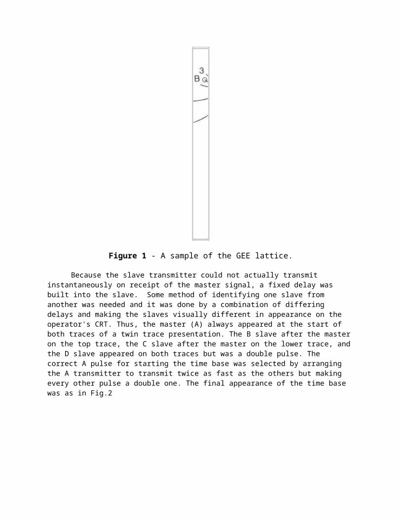
The operating principle of Gee was the transmission of short (6 microsecond) pulses at frequencies around 30 MHz (later extended up to 80 MHz., Signals sent from a master station were received at up to three slave stations and was used to synchronize their own transmissions. The slaves operated on the same frequency as the master (see figure 1). A slave transmission would therefore normally be received after the master, but on the baseline extension behind the slave the difference would be zero and the pulses would overlap.
Figure 1 - A sample of the GEE lattice.
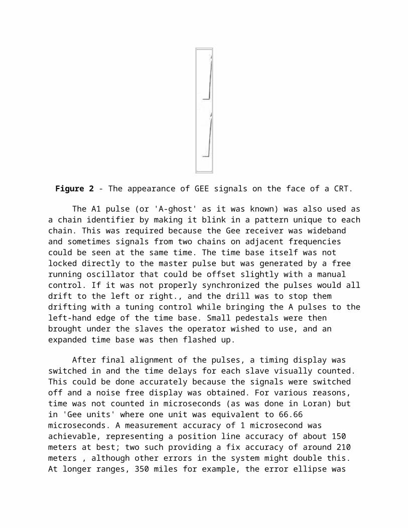
Because the slave transmitter could not actually transmit instantaneously on receipt of the master signal, a fixed delay was built into the slave. Some method of identifying one slave from another was needed and it was done by a combination of differing delays and making the slaves visually different in appearance on the operator's CRT. Thus, the master (A) always appeared at the start of both traces of a twin trace presentation. The B slave after the master on the top trace, the C slave after the master on the lower trace, and the D slave appeared on both traces but was a double pulse. The correct A pulse for starting the time base was selected by arranging the A transmitter to transmit twice as fast as the others but making every other pulse a double one. The final appearance of the time base was as in Fig.2
Figure 2 - The appearance of GEE signals on the face of a CRT.
The A1 pulse (or 'A-ghost' as it was known) was also used as a chain identifier by making it blink in a pattern unique to each chain. This was required because the Gee receiver was wideband and sometimes signals from two chains on adjacent frequencies could be seen at the same time. The time base itself was not locked directly to the master pulse but was generated by a free running oscillator that could be offset slightly with a manual control. If it was not properly synchronized the pulses would all drift to the left or right., and the drill was to stop them drifting with a tuning control while bringing the A pulses to the left-hand edge of the time base. Small pedestals were then brought under the slaves the operator wished to use, and an expanded time base was then flashed up.
After final alignment of the pulses, a timing display was switched in and the time delays for each slave visually counted. This could be done accurately because the signals were switched off and a noise free display was obtained. For various reasons, time was not counted in microseconds (as was done in Loran) but in 'Gee units' where one unit was equivalent to 66.66 microseconds. A measurement accuracy of 1 microsecond was achievable, representing a position line accuracy of about 150 meters at best; two such providing a fix accuracy of around 210 meters , although other errors in the system might double this. At longer ranges, 350 miles for example, the error ellipse was about 6 miles by 1 mile. While not remarkable by today's standards, it was revolutionary at the time and far in advance of any other method of fixing.
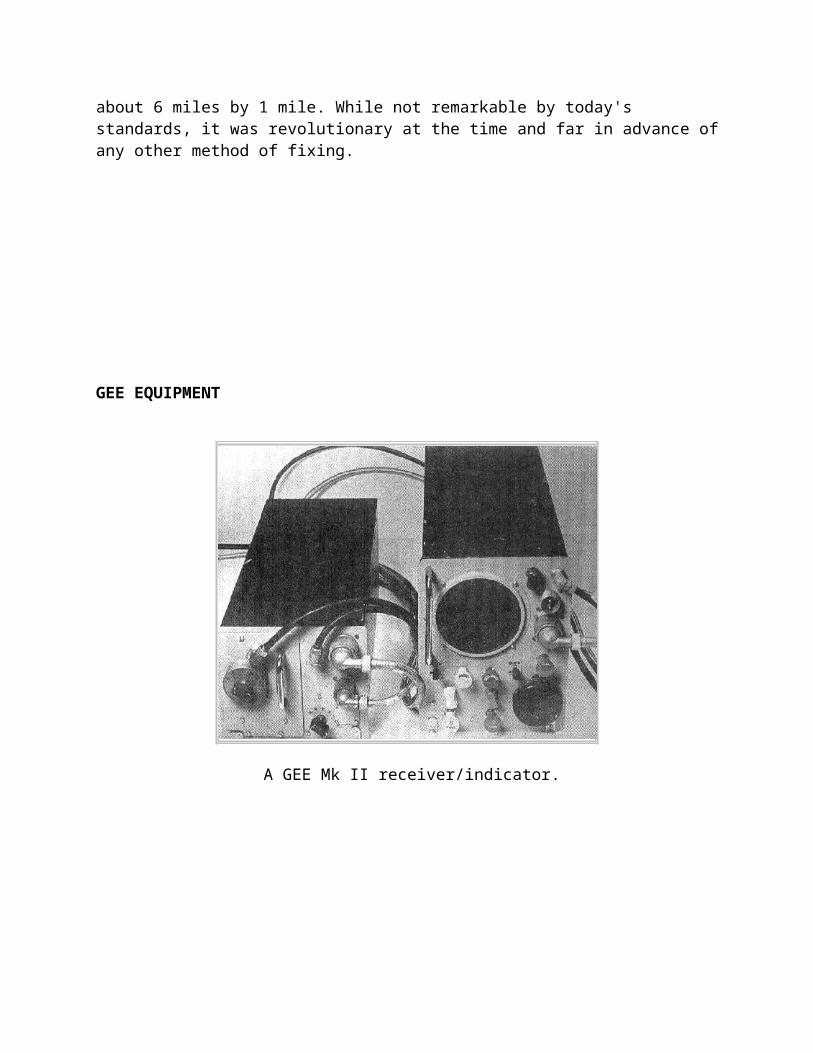
GEE EQUIPMENT
A GEE Mk II receiver/indicator.
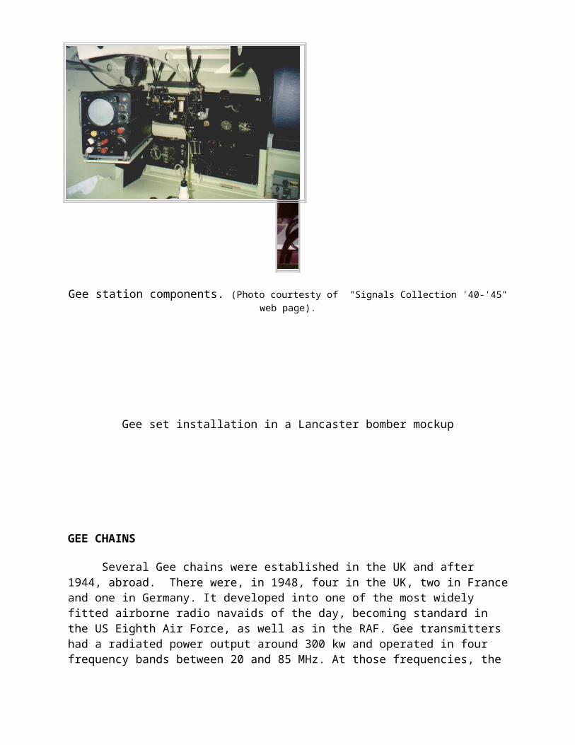
Gee station components. (Photo courtesty of "Signals Collection '40-'45" web page).
Gee set installation in a Lancaster bomber mockup
GEE CHAINS
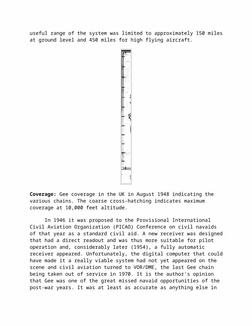
Several Gee chains were established in the UK and after 1944, abroad. There were, in 1948, four in the UK, two in France and one in Germany. It developed into one of the most widely fitted airborne radio navaids of the day, becoming standard in the US Eighth Air Force, as well as in the RAF. Gee transmitters had a radiated power output around 300 kw and operated in four frequency bands between 20 and 85 MHz. At those frequencies, the useful range of the system was limited to approximately 150 miles at ground level and 450 miles for high flying aircraft.
Coverage: Gee coverage in the UK in August 1948 indicating the various chains. The coarse cross-hatching indicates maximum coverage at 10,000 feet altitude.
In 1946 it was proposed to the Provisional International Civil Aviation Organization (PICAO) Conference on civil navaids of that year as a standard civil aid. A new receiver was designed that had a direct readout and was thus more suitable for pilot operation and, considerably later (1954), a fully automatic receiver appeared. Unfortunately, the digital computer that could have made it a really viable system had not yet appeared on the scene and civil aviation turned to VOR/DME, the last Gee chain being taken out of service in 1970. It is the author's opinion that Gee was one of the great missed navaid opportunities of the post-war years. It was at least as accurate as anything else in use, and far more accurate than most; nor did it suffer from sky wave and static problems anywhere nearly as badly as did many of the lower frequency systems. It was perfectly suited to aviation, its line-of-sight range being no drawback, and there is not the slightest doubt that, had investment been made in more modern transmitters and receivers, it could have been made fully automatic and even more accurate.
DECCA NAVIGATION SYSTEM
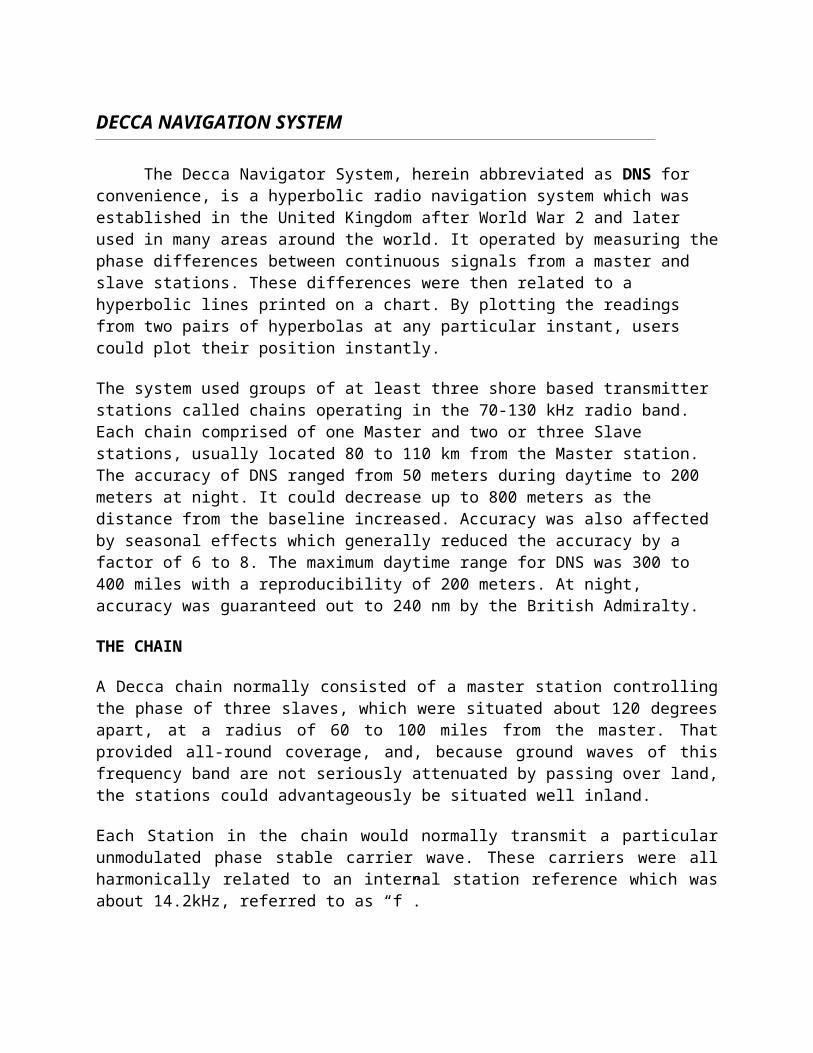
The Decca Navigator System, herein abbreviated as DNS for convenience, is a hyperbolic radio navigation system which was established in the United Kingdom after World War 2 and later used in many areas around the world. It operated by measuring the phase differences between continuous signals from a master and slave stations. These differences were then related to a hyperbolic lines printed on a chart. By plotting the readings from two pairs of hyperbolas at any particular instant, users could plot their position instantly.
The system used groups of at least three shore based transmitter stations called chains operating in the 70-130 kHz radio band. Each chain comprised of one Master and two or three Slave stations, usually located 80 to 110 km from the Master station. The accuracy of DNS ranged from 50 meters during daytime to 200 meters at night. It could decrease up to 800 meters as the distance from the baseline increased. Accuracy was also affected by seasonal effects which generally reduced the accuracy by a factor of 6 to 8. The maximum daytime range for DNS was 300 to 400 miles with a reproducibility of 200 meters. At night, accuracy was guaranteed out to 240 nm by the British Admiralty.
THE CHAIN
A Decca chain normally consisted of a master station controlling the phase of three slaves, which were situated about 120 degrees apart, at a radius of 60 to 100 miles from the master. That provided all-round coverage, and, because ground waves of this frequency band are not seriously attenuated by passing over land, the stations could advantageously be situated well inland.
Each Station in the chain would normally transmit a particular unmodulated phase stable carrier wave. These carriers were all harmonically related to an internal station reference which was about 14.2kHz, referred to as “f”.
* The Master Station normally transmitting a “6f” unmodulated carrier wave signal in the 85 kHz band,
* Red Slave Station transmitting an “8f” signal in the 112 kHz Band,
* Green Slave transmitting a “9f” signal in the 127 kHz band,
* Purple Slave transmitting a “5f” signal in the 71 kHz band.
The Slave stations received and phase locked their station reference oscillators to the Master “6f” Transmission.
The frequency ranges for the master and slave stations were:
Master: 84 - 86 kHz
Red slave: 112 - 115 kHz
Green slave: 126 - 129 kHz
Purple slave: 70 - 72 kHz
Since the signals were continuous wave (CW), 150 Hz spacing was sufficient to ensure there would be no interference.
These transmissions were received by a special receiver and frequency multiplying circuits therein produced phase comparisons of:
24f for the Master and Red
18f for Master and Green
30f for the Master and Purple
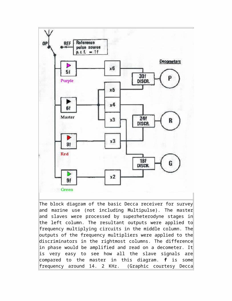
The block diagram of the basic Decca receiver for survey and marine use (not including Multipulse). The master and slaves were processed by superheterodyne stages in the left column. The resultant outputs were applied to frequency multiplying circuits in the middle column. The outputs of the frequency multipliers were applied to the discriminators in the rightmost columns. The difference in phase would be amplified and read on a decometer. It is very easy to see how all the slave signals are compared to the master in this diagram. f is some frequency around 14. 2 KHz. (Graphic courtesy Decca Navigator Co. Modified by Jerry Proc)
Although for most of the time the stations only transmitted their single carrier, during part of the transmission cycle, each station would transmit what was termed a Multi-pulse also called "Mark 10" transmission. In the Mark 10 context, it meant that Multipluse could only be received on Mk X receiver equipment and higher.
The Multi-pulse was transmitted by each of the stations in turn during the 20 second transmission cycle to provide a coarse reading, or a Zone reading, and was generated by all 5 transmitters at the given station briefly transmitting simultaneously. During transmission of the Multi-pulse by, say the Red Slave, all transmissions from the other stations in the Chain would be suppressed.
The original 'V type transmissions, prior to the introduction of Multipulse also had V-1 and V-2 variants. Both of these were being phased out by the mid-'70's when many of the chains were being updated. More on this as soon as additional information becomes available.
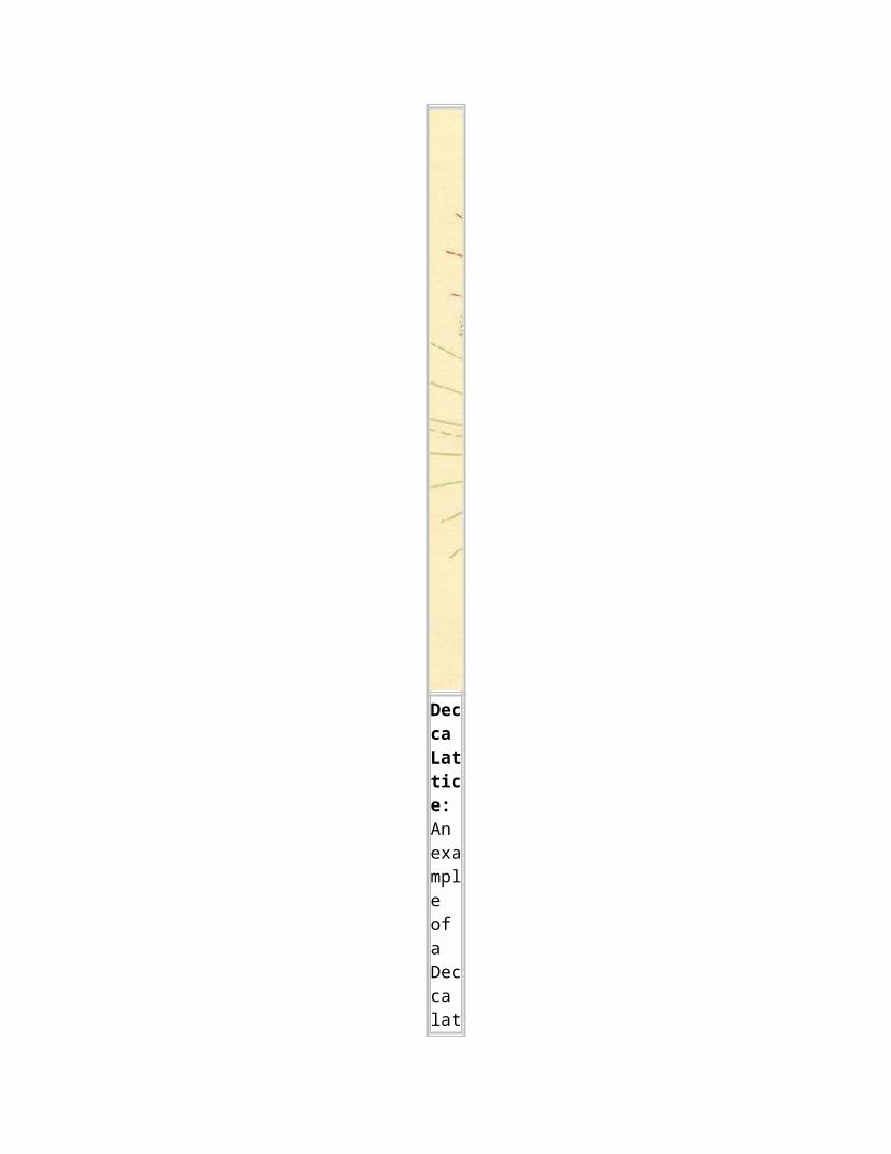
Decca Lattice: An exa

mple of a Decca lattice chart showing the lines of hyperbola from the read and green slaves.
The transmissions from the chain are received by a special shipborne receiver, which measures the difference in phase of signals arriving from master and slaves. All stations in a Decca chain must 'phase locked', and this has to be done over an appreciable distance separating the stations, sometimes up to 100 nautical miles, the phase difference being determined by this distance. Each slave station is fitted with equipment which receives the master signal, converts it to the slave frequency, and uses it to control the drive oscillator of the slave transmitter. Thus a constant phase relationship is maintained. To ensure that this relationship is maintained accurately, a monitoring station checks the transmissions.
DECOMETERS
The detected phase differences are displayed on phase meters called 'decometers', and the readings may be plotted onto Decca lattice charts, on which the lines of position are numbered in the same units as those shown on the decometers.
The decometer indications are continuous, and depending on the position in the coverage, readings of the two appropriate decameters can be taken simultaneously whenever a fix is required. The third decameter can give some additional information, but usually its readings are disregarded in the wide sector around the base-line extension. The lattice patterns are formed by hyperbolic position lines similar to those previously described. They are overprinted on ordinary Mercator charts. The slave stations are known as Red, Green and Purple slaves, according to the printed colour of the lattice lines derived from their transmissions.
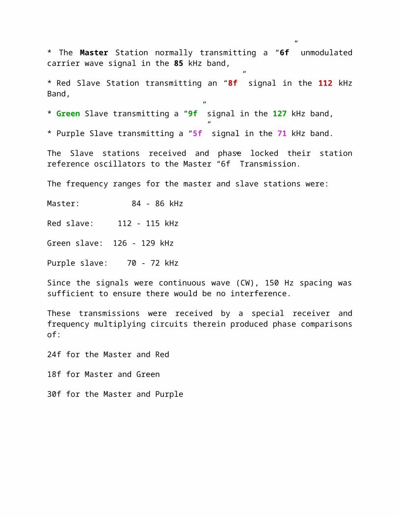
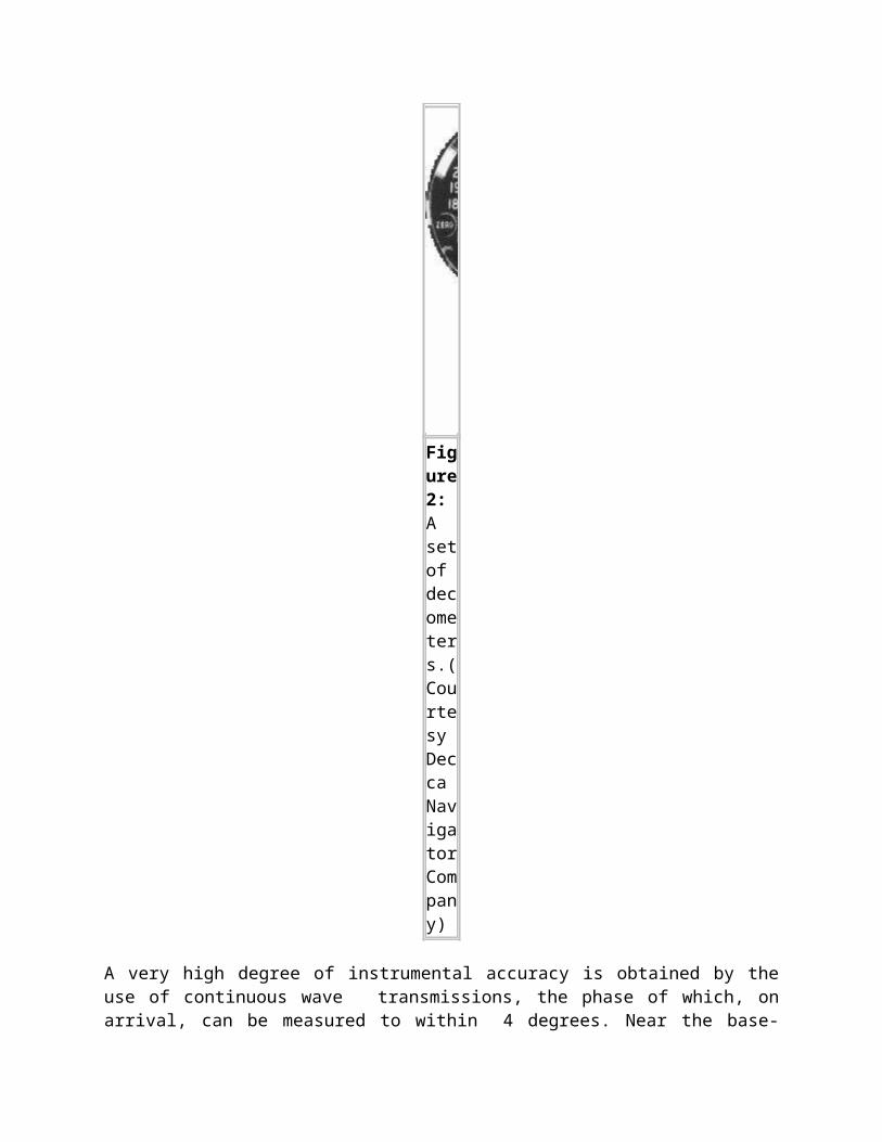
Figure 2: A set of decometers.( Courtesy Decca Navigator Company)
A very high degree of instrumental accuracy is obtained by the use of continuous wave transmissions, the phase of which, on arrival, can be measured to within 4 degrees. Near the base-line, between a pair of stations, this may represent a distance as small as 10 yards, though it must be borne in mind that constant and variable errors due to operational causes exist in the system, which, in practice, does not normally give an accuracy as good as +/- 10 yards. It is, however, considerably more accurate than any system employing pulse transmissions ( ie Loran).
LANES
The areas between the lines of zero phase difference in a Decca pattern are known as "lanes". The width of each lane on the base-line is approximately Red: 450 metres, Green: 590 metres and Purple: 350 metres. Lanes are grouped into Zones. Each Zone contains 24 Red lanes, 18 Green lanes, or 30 Purple lanes. For unambiguous presentation, the Zones are lettered, and the Lanes numbered outwards from the Master Station. Each group of ten Zones is lettered from A to J, and the Lanes in each zone are numbered:- Red: 0 to 23, Green: 30 to 47 and' Purple: 50 to 79. Readings at the Master Station are Red 0.00, Green A 30.00 and Purple A 50.00. The correct Zone Letter must be determined from normal navigational methods and by reference to the appropriate Decca latticed chart. As the zones are about 6 miles in width on the base lines, and this width increases away from the base-lines, the accepted position of the ship is generally not critical for this purpose.
It is essential that the signals from the two stations should be received separately in order to preserve their individual phase properties. Since the C.W. transmissions are simultaneous, this can only be achieved by transmitting on different frequencies: but these frequencies must have an exact common multiple. The transmissions are received by what are virtually four separate receivers within the Decca Navigator receiving equipment. The frequencies of these signals are then multiplied up to their lowest common multiple, the so-called "comparison frequency" on which the phase comparison is made. As the pattern is traversed by the Decca receiving equipment so the reading will be observed to alter steadily from 0 degrees to 360 degrees between the limits of each lane; the decometer, from which this reading is obtained, is therefore graduated in fractions of a lane instead of in degrees.
INTERPOLATOR: Shown above is the Interpolator
for Decca Lattice Charts. When overlaid on a lattice chart, it would help the navigator resolve the distance between lattice lines. (This artifact was donated to HMCS
HAIDA Historic Naval Ship by Duncan Mathieson)
The decometer is simply a phase meter whose dial is graduated in hundredths of a lane width; one revolution of the fractional pointer represents the extent of one lane. It will, therefore, indicate very accurately a receiver's position between two lattice lines, but it is unable to identify the particular lane in which it is situated. Since lane width varies from less than a mile near the base line to 3 miles or so at 300 miles range, this would cause a high degree of ambiguity, which a ship, entering the coverage area after an ocean passage, might not be able to resolve. Once the initial position has been established, however, the decometer, which is capable of continuous rotation, can integrate its movements in the lattice pattern by a set of counters geared to the fractional pointer.
LANE IDENTIFICATION METER
The ambiguity of the Decca Navigator system has been resolved in the Mark V (or QM5) receiver by the addition of a fourth dial called a "Lane Identification Meter". Its use enables the operator to set each decometer to the correct lane within a zone. He must still know which zone his ship is situated in, however, in order to set the correct letter on the decometer. Since a zone consists of about twenty or more lanes, this only requires that the dead reckoning position should be known within wide limits so that, except in unusual cases, no ambiguity should arise.
Should lane-slip have occurred, the fact will be apparent from the lane identification meter as soon as the ship enters the lane identification coverage area and the decometers can be reset accordingly. Essentially, lane identification consists of transmissions from master and slave at much lower frequency than the normal. This lower frequency, which is used as a comparison frequency in the receiver, is actually obtained as a beat frequency of the two transmissions originating from the same station. Thus a very much coarser pattern is obtained in which the 360 degree phase change corresponds to a whole zone. Since this lower frequency is a multiple of the pattern comparison frequency, a zone comprises a whole number of lanes. This is shown in figure 3. The lane identification meter, which measures phase difference in the same way as the decometer, will indicate the position within a zone.
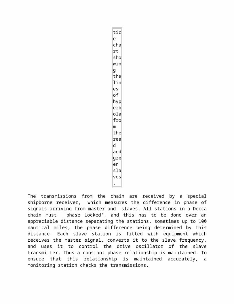
Figure 3: Lane identification transmission.
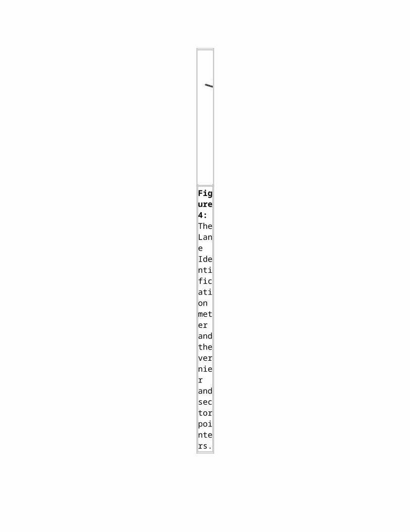
If this meter is graduated in lanes, instead of fractions of a zone, it will then indicate directly the correct lane in which the receiver lies. In practice, the lane identification meter has three concentric scales (one for each pair of stations), coloured red, green and purple. Lane identification signals are transmitted from each pair in a fixed sequence at short intervals; and, as each one is received, a relay is closed, illuminating the appropriate coloured scale while the pointer indicates the correct lane on that scale. The indication for each colour remains on the meter for about 5 seconds, which is ample time in which to obtain a reading. This was due to the discovery that, in certain conditions of skywave interference, the accuracy of the meter responding to the coarse pattern was inadequate for the required purpose. The indicator consists, therefore, of two separate components: the sector pointer and the "vernier" pointer assembly. The former indicates the position to the nearest sixth of a zone, while the latter, working on an intermediate frequency, indicates the actual lane itself within that zone.
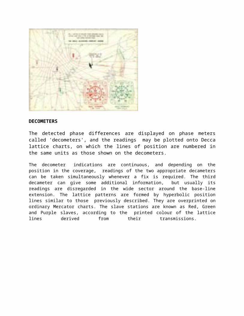
Figure 4: The Lane Identification meter and the vernier and sector pointers.
The vernier indicator is basically a meter with a pointer revolving once as the receiver travels across the space between two adjacent boundaries of a lane (a sixth of the width of a zone) of the particular pattern which affects it; but, for compactness of display, the action is geared down six times mechanically, and the single pointer is replaced by an assembly of six pointers, which are read against the same scale as the sector pointer.
It should be noted that the word "vernier" is used in this connection not in its true sense, but merely to indicate a finer indication. A reading is effected by noting, on the illuminated scale, the lane number indicated by the particular vernier pointer which is enclosed by the arms of the
sector pointer. Thus, in Figure 4, if the red scale were illuminated on the meter, the correct lane reading would be between 7 and S. It should be noted that, beyond 100 miles from the base line, the center of the sector pointer will not always coincide with the vernier pointer, owing to skywave interference; but as the vernier pointer indicates the exact lane, this will cause no inaccuracy. Near the limits of coverage at night, however, the arms of the sector pointer may coincide exactly with two vernier pointers, or the sector pointer may even enclose the wrong one. The use of lane identification was approved by the British Ministry of Transport in 1949, subject to strict compliance with the instructions contained in the relevant Data Sheets, which were promulgated by the Decca Navigator Company from time to time.
CHAIN OPERATION
DESCRIPTION OF 'V' TYPE TRANSMISSIONS
Each station in a Decca chain transmits on a different frequency. If the master and slave stations all operated on the same frequency, the receiver would be unable to distinguish between the incoming signals. In order to compare the phases, however, all the transmission frequencies are related harmonically, and each signal is separately converted in the receiver to a frequency which is the lowest common multiple of the master and slave frequencies. The relative phases can then be compared at this "comparison frequency", which will be different for each pair. For example, if the Master, A, transmits on 60 kc/s and slave B transmits on 80 kc/s, the comparison frequency would be 240 kc/s, which is the lowest common multiple (LCM) of 60 and 80. As far as the receiver is concerned, apart from signal separation, the waves appear to have travelled from the transmitters at the comparison frequency, and it is upon this frequency that the number of lanes in a lattice depends.
Remembering that one lane is half-a-wavelength wide along the base-line, and taking 240 kc/s as the comparison frequency of the AB pair, we obtain the following: 240 kc/s is equivalent to a wavelength of 1,370 yards i.e., each lane will be 685 yards wide along the base-line. If the distance between A and B is 85.5 miles, then the number of lanes will be: 85.5 x 2,000/ 685 = 250
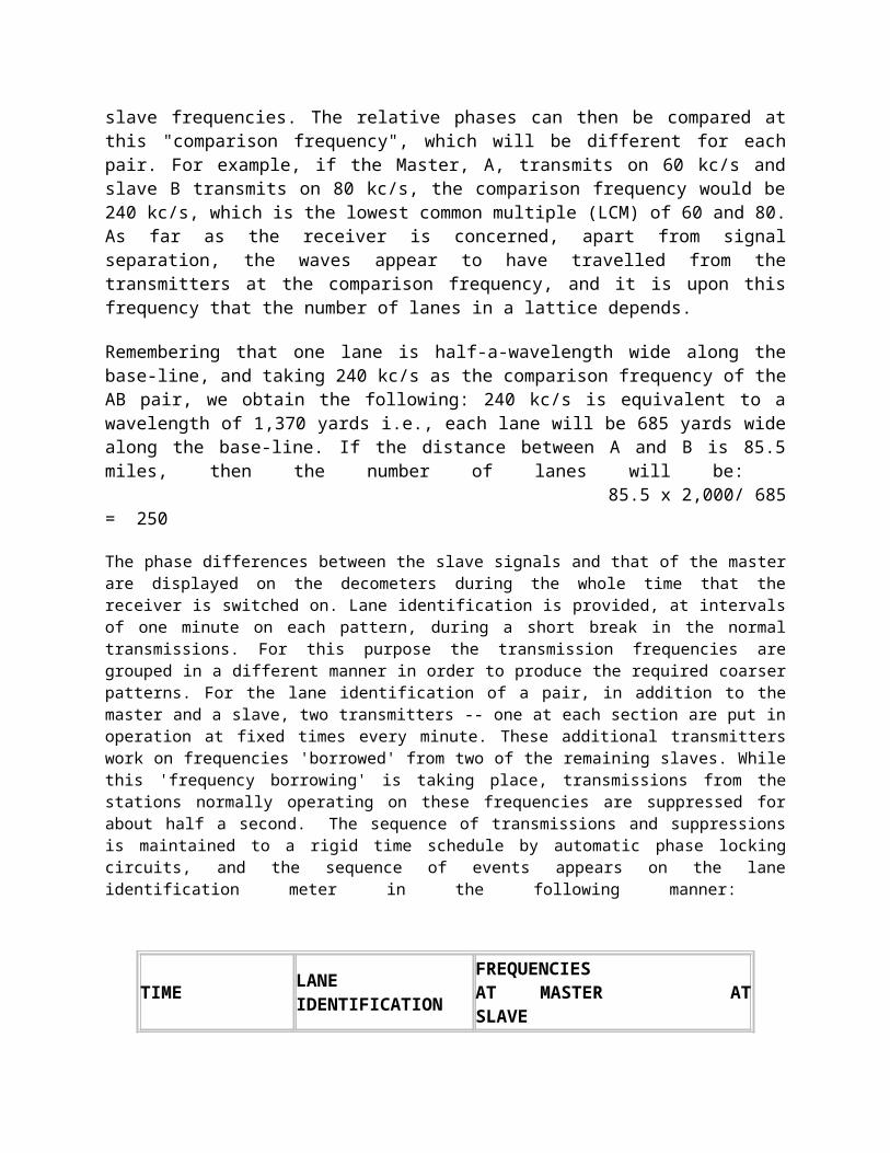
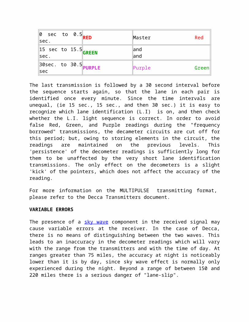
The phase differences between the slave signals and that of the master are displayed on the decometers during the whole time that the receiver is switched on. Lane identification is provided, at intervals of one minute on each pattern, during a short break in the normal transmissions. For this purpose the transmission frequencies are grouped in a different manner in order to produce the required coarser patterns. For the lane identification of a pair, in addition to the master and a slave, two transmitters -- one at each section are put in operation at fixed times every minute. These additional transmitters work on frequencies 'borrowed' from two of the remaining slaves. While this 'frequency borrowing' is taking place, transmissions from the stations normally operating on these frequencies are suppressed for about half a second. The sequence of transmissions and suppressions is maintained to a rigid time schedule by automatic phase locking circuits, and the sequence of events appears on the lane identification meter in the following manner:
TIME LANE FREQUENCIES
IDENTIFICATION AT MASTER AT SLAVE
0 sec to 0.5 sec. RED Master Red
15 sec to 15.5 sec. GREEN and and
30sec. to 30.5 sec PURPLE Purple Green
The last transmission is followed by a 30 second interval before the sequence starts again, so that the lane in each pair is identified once every minute. Since the time intervals are unequal, (ie 15 sec., 15 sec., and then 30 sec.) it is easy to recognize which lane identification (L.I) is on, and then check whether the L.I. light sequence is correct. In order to avoid false Red, Green, and Purple readings during the "frequency borrowed" transmissions, the decameter circuits are cut off for this period; but, owing to storing elements in the circuit, the readings are maintained on the previous levels. This 'persistence' of the decometer readings is sufficiently long for them to be unaffected by the very short lane identification transmissions. The only effect on the decometers is a slight 'kick' of the pointers, which does not affect the accuracy of the reading.
For more information on the MULTIPULSE transmitting format, please refer to the Decca Transmitters document.
VARIABLE ERRORS
The presence of a sky wave component in the received signal may cause variable errors at the receiver. In the case of Decca, there is no means of distinguishing between the two waves. This leads to an inaccuracy in the decometer readings which will vary with the range from the transmitters and with the time of day. At ranges greater than 75 miles, the accuracy at night is noticeably lower than it is by day, since sky wave effect is normally only experienced during the night. Beyond a range of between 150 and 220 miles there is a serious danger of "lane-slip".
Disregarding systematic errors and transmission failures, the accuracy of a fix from the Decca system can be considered to depend upon:
(a) Instrumental errors
(b) Propagation errors caused by either Sky Wave or Coastal effects.
(c) Lane width.
(d) Angle of cut of the hyperbolae.
Thus Decca errors are subject to many variables and cannot be summarized precisely. The following figures give a guide to the accuracy that should generally be expected:
a) By DAY 0-100 miles or by NIGHT 0-75 miles: +/- 10 feet near base line; 1 mile at limits
b) By NIGHT 75-240 miles: Up to a maximum of about 5 miles, depending on sighting of slave stations.
Notification of any transmission failures, which might result in lane slipping, were promulgated to mariners by signals broadcast from certain coastal radio stations. Details of this service was contained in the Admiralty List of Radio Signals (Vol. V). Decca Charts.
Decca charts, produced by the Hydrographer, consisted of Admiralty navigational charts overprinted with Decca lattices. They were given the series letter 'L' with the word 'Decca' in brackets after the number - e.g., L 1408 (Decca) - to distinguish them from other lattice charts.
POPI (Research)
The POPI (Post Office Position Indicator) of 1946 was another phase-comparison low-frequency (40 kHz) system that had some features of Consol and of Decca. It was to use aerials situated on a short baseline radiating the same frequency but not simultaneously, alternating between the two aerials at five times a second. Because of the short baseline, the resultant hyperbolae degenerated into radials very rapidly. A third aerial equispaced from the other two served to resolve ambiguities somewhat, and there was a novel method of actually measuring the phase differences, using a fourth transmitter in the middle of the other three. The system was never actually put into use, but the work done on it was later acquired by Decca, after an American system, Navarho, used some of its ideas.
LORAN A
No great effort was put into hyperbolic navaids in the US until it became clear that America could not avoid involvement in W.W. II. Before 1940, the US military forces were small and under funded, and there was no separate Air Force, only Army and Navy Air Corps. Like most other military air arms of the time, little attention had been paid to the problems of accurate navigation over hostile territory and no requirement for accurate radio navaids had been formally stated. In 1940, under the aegis of the National Defense Research Committee, a Microwave Committee was set up to examine what new developments would be needed if the US became involved in the European War. One of these (known as Project 3 according to the official history of the period, but as Project C according to Professor Jack Pierce, who was a member of the development team) was to be a pulsed hyperbolic radio navigation system operating in the low end of the VHF spectrum, at about 30 MHz - very like Gee, which the Americans knew nothing about at the time. It eventually became the Loran-A system, out of which Loran-C was born. Loran-A operated in the 1850 to 1950 kHz band, used pulse-time difference as its operating principle and generally speaking had a day/night range of about 800 to 1600 nm depending on whose reference you read.
HISTORY
The US Army Signal Corps Technical Committee, at a meeting on October 1, 1940, wrote a specification calling for a precision radio navigation system with an accuracy of at least 1000 feet at a range of 200 miles. This was adopted as 'Project 3 (or C)' by the Microwave Committee and initial orders for equipment were placed in December 1940. In early summer 1941 it was handed over to the Radiation Laboratory Navigation Group, who, after some study, decided that the attainable ranges using 30 MHz might be too low for American requirements and that better results could be obtained at lower frequencies in the HF band. While the original 30 MHz transmitters were still being built, new transmitters were obtained to use frequencies between 3 and 8 MHz and experimental transmissions started in summer 1941. It became clear almost immediately that the lower frequencies around 3 MHz were more stable, but there were considerable difficulties making accurate time delay measurements. This was the same problem the Gee development team was having in the UK, but was compounded by the much longer pulses Loran-A was using at its lower frequencies. It should be remembered that at this time virtually no work had been done on high power low frequency pulse transmission, and the technique was in its infancy.
While these tests were proceeding, information was received from the UK liaison office in the USA about the Gee system, including some details of how Gee time measurements were being made. The US team were trying to use a circular time base to increase accuracy but had found it difficult, so the British technique of using delayed and strobed time bases was of great interest and was adopted immediately. Also, now having realized how far work had advanced on Gee, the US team saw no reason to duplicate the British work and abandoned any further work on the original Project 3. They foresaw that the main application of the new system would be for naval convoy work, and long range over sea water would be important. Comparative trials at different frequencies evaluating groundwave and skywave performance eventually led to the choice of 1.950 MHz as optimum and all subsequent
development work used this frequency. There was at one time an intention to supplement it with a second frequency of around 7.5 MHz for daytime long-range use, but it. was never implemented except for test purposes. For anyone who has used the APN Loran receiver, this explains the mystery of why there was a fourth position on the frequency selector marked 'HF'.
APN-4 photo courtesy of Signals Collection '40-'45
In mid-1942, R. J. Dippy, who had invented the Gee system, was sent to the USA for eight months to assist in Loran development. Many of the techniques used in Gee were adopted, and it was he who insisted that the Loran and Gee receivers were made physically interchangeable so that any RAF or USAAF aircraft fitted for one could use the other by simply swapping units. This was still to prove valuable, long after the war had finished, for Transport Command navigators flying the Australia run from the UK who could plug in the appropriate set depending on where they were. He also designed the ground station timing and synchronization equipment and his assistance speeded up Loran development considerably. Once design had been finalized, production went ahead rapidly. The first Loran-A pair was on the air permanently by June 1942 (Montauk Point, NY, and Fenwick Is, Del.), and by October there were additional stations along the Canadian east coast. The system became operational in early 1943, and late that year stations were established in Greenland, Iceland, the Faeroes and the Hebrides to complete the North Atlantic cover, some being operated by the Royal Navy. At the request of the RAF, another station was put into the Shetlands to cover Norway, and Loran was eventually used by over 450 aircraft of Coastal Command.
But it was in the Pacific that Loran made its greatest direct contribution to winning the war. Distances in the Pacific Ocean are enormous. As American forces moved westward, air fields were built on many of the small islands and atolls that dot the ocean beyond Hawaii. The limited range of many World War II aircraft demanded that they frequently land and refuel. Navigation by celestial observations is possible only when weather permits and, moreover, it requires a highly trained man who does little on the plane except navigate. Because of the lengthy training required, celestial navigators, particularly on Army Air Corps planes, were extremely scarce. Thus it was that loran provided the easy-to-use, accurate navigational system required to and the air gelds so necessary for refueling.
The intensive bombing of Japan began as soon as air bases could be secured near enough for aircraft to make the round trip. Accurate navigation was necessary not only for precision bombing, but also for carrying a maximum bomb load instead of a large reserve of gasoline. The loran system provided the means for this accurate navigation. By the end of World War II there were 75 standard loran stations serving the needs of aircraft and vessels in operation with over 75,000 receivers in use. Coverage in the Japanese and East China Sea Areas was extended in the 1950's
The crews of Loran stations varied somewhat in size, depending on their locations. They have averaged about fifteen men. As the stations had to be entirely self-sufficient, they had cooks, hospital corpsmen, damage controlmen, and enginemen, in addition to the electronic technicians who operated and maintained the transmitters. Each station was commanded by a commissioned officer, usually a lieutenant (junior grade ), with a chief petty officer as second in command. Prospective commanding officers were given a short training course in Loran and administration before assignment. Command of a Loran station was almost invariably a young a Coast Guard officer's first independent assignment, and it provided an excellent opportunity for him to demonstrate his leadership qualities. Many young others dreaded Loran duty because of the isolation, but after it is over, nearly all of them felt it had been well worthwhile. At isolated stations, tours of duty were for one year. The great majority of Loran stations were supplied with fuel, bulky spare parts, and large staple items by a Coast Guard supply ship which called once or twice a year. Unless they were located near a large community, Loran stations received mail, personnel, fresh stores, and emergency spare parts by Coast Guard airplane. Most stations had their own airstrip.
This was a typical USCG Loran-A station in the SW Pacific. Generally spea
king, Loran-A had an average expected accuracy of 1 percent of the distance between the navigator and the stations according to the U.S. Coast Guard in 194
9. (Photo courtesy Ken Laesser's Coast Guard History Page)
In many places throughout the Pacific, Coast guardsmen were the only Americans ever seen by the natives, and it is to their credit that unpleasant incidents were few and far between. In fact, relationships were usually excellent. A good example was the Okinawa Loran Station which was located on a small island just of Okinawa itself . Here on Ichi Benare, the Loran station personnel were the only Americans. The island is infested with a venomous snake, a species of pit viper. When left untreated, the bite of this snake is usually fatal. The hospital corpsman of the station always keeps a supply of anti-venin fox station use, but he also used it to treat those natives unfortunate enough to be snakebite. On the wall of this station hung a scroll, signed by the mayor of the native village, expressing thanks fox having saved so many of the villagers' lives.
The Pusan Loran Station was part of the East China Sea chain, while the other two stations were located on the west coast of Japan. This chain was established to furnish accurate positions to United States aircraft approaching the Korean Peninsula. The Pusan station was built on a bluff overlooking the East China Sea, a few miles from the city of Pusan, Korea. Ever since it was first built, this station was harassed by bandits. It was completely surrounded by barbed wire, has many foxholes and slit trenches, and for years personnel were frequently called upon to defend themselves against marauders.
Still another station was Naulo Point located on the west coast of Luzon in the Philippines. Because of its dry and relatively cool weather (unlike that of other Phillippine stations ) Loran people called it "The Garden Spot of the Pacific.'' It is in the heart of what was once the "Huk country" and during the Huk uprisings was guarded continuously by a company of United States Marines. For years the barbed wire entanglements, entrenchments, and floodlights remained as a mute reminder of former violence.
In 1965 Loran stations were established in Portugal and the Azores. One major difference in the way Loran-A operated compared with Gee was that its transmitters operated in pairs rather than as chains.
LORAN SECURITY
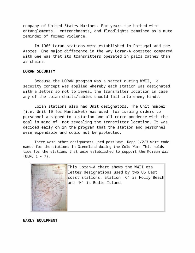
Because the LORAN program was a secret during WWII, a security concept was applied whereby each station was designated with a letter so not to reveal the transmitter location in case any of the Loran charts/tables should fall into enemy hands.
Loran stations also had Unit designators. The Unit number (i.e. Unit 10 for Nantucket) was used for issuing orders to personnel assigned to a station and all correspondence with the goal in mind of not revealing the transmitter location. It was decided early on in the program that the station and personnel were expendable and could not be protected.
There were other designators used post war. Dope 1/2/3 were code names for the stations in Greenland during the Cold War. This holds true for the stations that were established to support the Korean War (ELMO 1 - 7).
This Loran-A chart shows the WWII era letter designations used by two US East coast stations. Station 'C' is Folly Beach and 'H' is Bodie Island.
EARLY EQUIPMENT
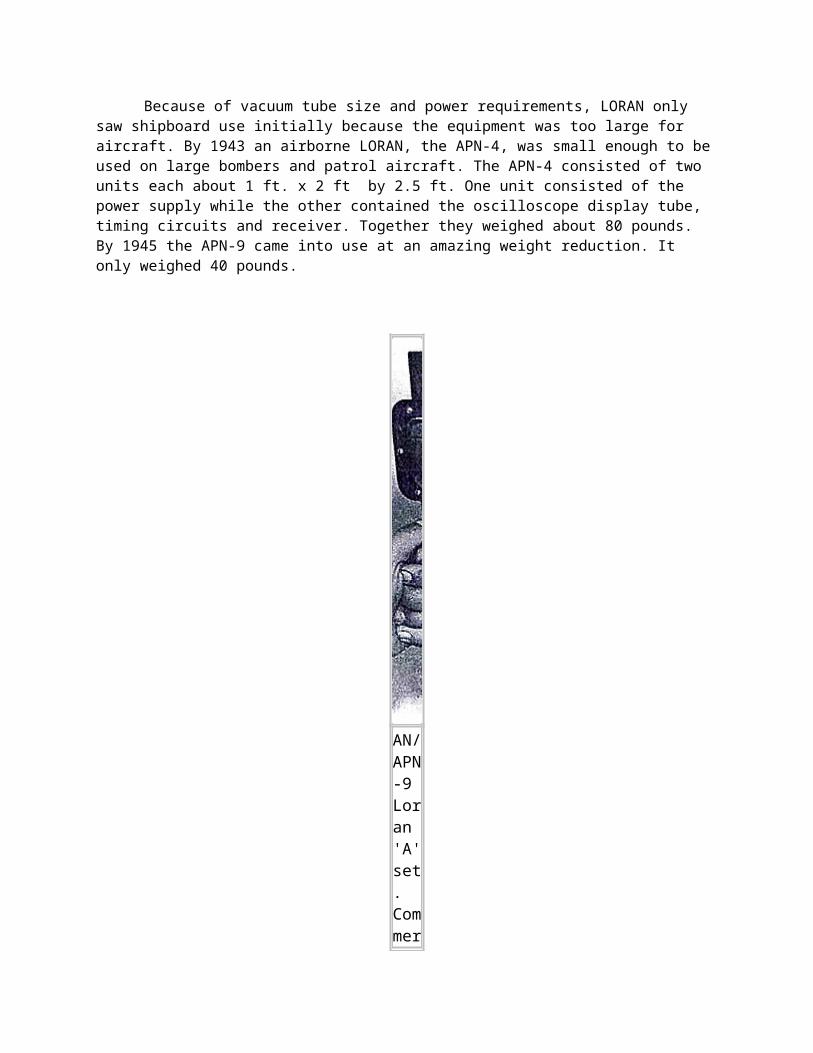
Because of vacuum tube size and power requirements, LORAN only saw shipboard use initially because the equipment was too large for aircraft. By 1943 an airborne LORAN, the APN-4, was small enough to be used on large bombers and patrol aircraft. The APN-4 consisted of two units each about 1 ft. x 2 ft by 2.5 ft. One unit consisted of the power supply while the other contained the oscilloscope display tube, timing circuits and receiver. Together they weighed about 80 pounds. By 1945 the APN-9 came into use at an amazing weight reduction. It only weighed 40 pounds.
AN/APN-9 Loran 'A' set. Commercial fishermen also used these after WW2 until
something better came on the market. (Image source unknown.)
The oscilloscope screen was about four inches in diameter and would display a station master and associated slave signal from about 1500 miles over water and 600 miles over land. With practice a fix could be determined in about three minutes. As an example, the minimum error for navigating the 1400 miles to Japan from Tinian was about 28 miles. With two successive fixes ground speed, drift, and ETA could be determined. The relative simplicity of LORAN and the fact that it could be used regardless of weather made it invaluable an invaluable navigational tool until the aircraft arrived over Japan when airborne radar provided a more accurate fix. For some unknown reason the Japanese either never tried or failed to jam any of the LORAN systems.
PRINCIPLES OF OPERATION
Loran provided facilities whereby ships and aircraft derived their position at long distances. The system required at least three transmitting stations for each 'chain', and the observer used a special Loran receiver. A chain consisted of one master and two slave stations. Differences in the arrival time of pulses from a pair of stations was measured and displayed on the face of a cathode ray tube. Each fix required two observations and the operation normally took about five minutes. The readings were then transposed to a Loran lattice chart and position could be plotted. In some cases readings were referenced to special Loran tables. Because Loran-A signals were pulsed and not continuous transmissions, tremendous peak power levels could be achieved by a relatively small transmitter. The maximum reliable range for Loran-A was 700 miles by day and 1,400 miles at night.
SIGNAL CHARACTERISTICS
Each transmission pulse lasted about 40 microseconds and reoccurred at regular, accurately controlled intervals. This interval, called the Pulse Repetition Interval (P.R.I.) varied for each station and lasted between 29,000 and 40,000 µs. These pulses provided precise index marks for
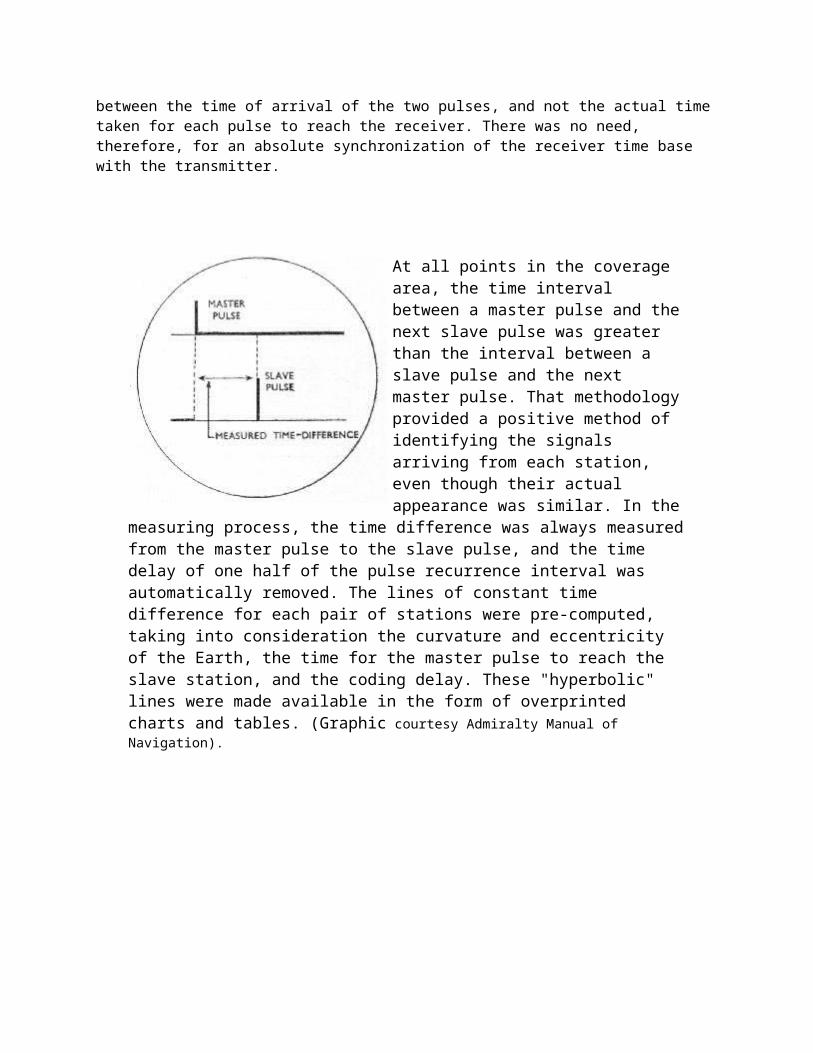
use in time measurements. The transmissions of corresponding master and slave pulses were separated by a fixed time interval which consisted of the time for a signal to travel from the master to the slave, plus one-half the P.R.I., plus an additional small time called the 'coding delay'. It should be noted that the observer is interested only in measuring the difference between the time of arrival of the two pulses, and not the actual time taken for each pulse to reach the receiver. There was no need, therefore, for an absolute synchronization of the receiver time base with the transmitter.
At all points in the coverage area, the time interval between a master pulse and the next slave pulse was greater than the interval between a slave pulse and the next master pulse. That methodology provided a positive method of identifying the signals arriving from each station, even though their actual appearance was similar. In the measuring process, the time difference was always measured from the master pulse to the slave pulse, and the time delay of one half of the pulse recurrence interval was automatically removed. The lines of constant time difference for each pair of stations were pre-
computed, taking into consideration the curvature and eccentricity of the Earth, the time for the master pulse to reach the slave station, and the coding delay. These "hyperbolic" lines were made available in the form of overprinted charts and tables. (Graphic courtesy Admiralty Manual of Navigation).
A sample Loran chart showing the location of a master and two slave stations. Also shown are
station identifiers and time differences on the curves. (Graphic courtesy of Electronic Communications).
ARRANGEMENT OF STATION PAIRS
When a common master controlled two slaves, the master was called a 'double pulsed' station because it transmitted two entirely separate sets of pulses, one set paired with the pulses from each adjacent station. Pairs of Loran stations were situated up to 600 miles and more apart.
Loran transmitters emitted 40 microsecond pulses. For H-rate pairs, the basic recurrence interval was every 30,000 microseconds; for L-rate pairs, 40,000 microseconds; and for S-rate pairs, 50,000 microseconds Each pulse had a peak power in excess of 200,000 watts, but since the duty cycle (the ratio of time the transmitter is on duty) for an L-rate pair, for example, is only 40/40,000, or 0.001, of the time, the transmitter has an average power output of only 200 watts or so. (200,000 x 0.001).
If any trouble occurred at either the master or the slave station that might impair the accuracy of the pulse timing, the transmitters operated on a 2 sec ON then 2 second OFF mode. This appeared to the operator as a blinking signal. Blinking signals were not used for navigation.
RECEPTION OF SIGNALS
In order to properly display the pulses to be measured, the receiver's time base had to synchronized so the length of the trace on the C.R.T. matched the P.R.I. of the station. Failing to
do so would cause the pulses to appear as if they were drifting to the left or to the right depending if the time base was too short or too long respectively.
The face of the C.R.T. in the receiver displayed two time base lines because a pair of stations were always being compared. For convenience, the upper trace was called the "A" trace and the lower one the "B" trace. By convention, the master station was displayed on the upper trace and the slave on the lower one. The time difference measurement was the horizontal distance from the master pulse to the slave pulse.
In an attempt to gain longer-range navigation, a variant of Loran-A was developed. It was known as SS (sky-wave-synchronized) Loran In the SS Loran system, the slave station of a pair was synchronized by a sky-wave pulse reflected from the 'E' layer, rather than by the ground wave as in standard Loran. This allowed the master and slave stations to be separated by as much as 1000 to 1200 miles. The Loran charts were calibrated in terms of sky waves, instead of ground waves, so that correction factors were unnecessary when sky waves were used. A disadvantage of the system was encountered when the indicator was located close to either or both stations, since erratic reception resulted when the angle of reflection of the sky wave from the.E layer approached the critical angle. As the critical angle was approached, the radio waves exhibited increasing penetrating power and would go entirely or part way through the 'E' layer.
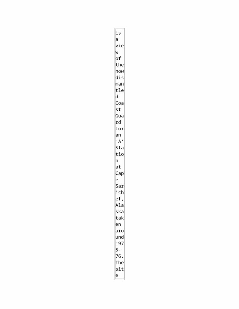
This is a view of
the now dismantled Coast Guard Loran 'A' Station at Cape Sarichef, Alaska taken around 1975-76. The site was located on Unimak Island, in the Aleutian Islands.
Access to the isolated island was by aircraft or helicopter only. From the photo collection of Bruce Gray (www.brucegray.com)
IDENTIFICATION OF LORAN-A PAIRS
Loran-A stations did not transmit call signs. Instead, identification was made entirely by two distinguishing characteristics: a) radio frequency channel b) pulse repetition rate.
A) By Channels
Different groups of Loran stations operated on different frequencies Four fixed frequencies were available between 1,750 and 1,950 kc/s. The receiver was fitted with a channel selector switch for tuning to the desired frequency. They were assigned the following designations:
Channel 1 - 1,950 kc/s Channel 2 - 1,850 kc/s Channel 3 - 1,900 kc/s Channel 4 - 1,750 kc/s
B) By Pulse Repetition Rate
In order to economize on frequency channels, a number of pairs of Loran stations were operated on the same frequency, but each pair operated at a different pulse repetition rate. That meant that signals from all stations on the same frequency within range appeared on the indicator, but they drifted across the scan at varying speeds. The operator selected a particular pair of stations by means of switches on the receiver which make the sweep repetition rate of the indicator the same as the pulse repetition rate of the desired pair. The desired signals would now be stationary, while the remainder still drifted across the scan and could be ignored.
Two switches were provided. The first one adjusted for the basic pulse repetition rate, of which there were three in advanced Loran sets: High, Low and Slow. The second switch adjusted for a specific pulse repetition rate differing from the basic by a small amount. There were eight of these specific rates, numbered 0 to 7, for each basic pulse repetition rate. This system thus provided 96 separate station pairs using the four frequency channels available.
STATION IDENTIFICATION SYMBOLS
Each pair of Loran-A stations was given a three character identification symbol, of which the first character was the channel; the second was the basic pulse repetition rate, and the third for the specific pulse repetition rate. These symbols were given in the Loran Tables, on printed on the charts. All stations were listed in the Admiralty List of Radio Signals - Vol 5.
In addition, each station was allocated an arbitrary station letter. For example, the N.E. Atlantic. chain consisted of:
Master station : U, at Skuvanaes Slave station : K, at Vik Slave station A, at Mangersta.
These letters were not transmitted. The frequency of this chain was 1,950 kc/s (Channel 1) and the basic pulse repetition rate was LOW. The specific pulse repetition rate of pair U-K is 5, and that of U-A is 6. Thus, the U-K pair was designated 1 L 5, and the U-A pair was 1 L 6.
In order to receive the first pair of stations, the operator had to set the receiver as follows: 1. Set the Channel switch to 1.
2. Set the basic P.R.R. switch to L. 3. Set the specific pulse repetition rate (5)
1950: A view of international Loran-A coverage in 1950.Click to enlarge. (Chart provided by Bill Dietz, Loran-A History Web Site)
1973: A view of international Loran-A coverage in 1973.Click to enlarge. (Courtesy of the Defence Mapping Agency, Hydrographic Center, Washington, D.C.)
When looking at Loran-A coverage maps, stations in the southern hemisphere are conspicuously absent. Bill Dietz of the Loran-A history web site offers this explanation. "LORAN was established for military needs during WWII. After the war, some stations were closed while others were established over the course of years as political climates dictated. However, one thing did remain a factor...all overseas Loran transmitting sites (both A and C) and support commands were funded by the US DoD and operated by the US Coast Guard.
That included training, support (parts and maintenance), personnel and funding for host nation station operations also. There were one or two countries that did provide their own funding. I believe England and France funded their own operations, but for the most part the U.S. government provided the funding".
PULSE REPETITION RATES
The following base pulse repetition rates were used:
H = 33 1/3 pps L = 25 pps S = 20 pps (for later equipment)
The eight variants of PRR and three ranges (H, L, S) produce the following PRR variants:
H0 = 33 3/9 pps L0 = 25 pps S0 = 20 pps
H1 = 33 4/9 pps L1 = 25 1/16 pps S1 = 20 1/25 pps
H2 = 33 5/9 pps L2 = 25 2/16 pps S2 = 20 2/25 pps
H3 = 33 6/9 pps L3 = 25 3/16 pps S3 = 20 3/25 pps
H4 = 33 7/9 pps L4 = 25 4/16 pps S4 = 20 4/25 pps
H5 = 33 8/9 pps L5 = 25 5/16 pps S5 = 20 5/25 pps
H6 = 34 pps L6 = 25 6/16 pps S6 = 20 6/25 pps
H7 = 34 1/9 pps L7 = 25 7/16 pps S7 = 20 7/25 pps
Therefore 4 basic frequencies x 3 PRR rates x 8 PRR variations = Maximum of 96 pairs of stations. On an ordinary radio receiver, a Loran station sounded like a continuously firing machine gun that changed tone slowly.
EQUIPMENT TYPES
The model DAS-2 was a popular Loran-A
receiver. (Graphic courtesy of Admiralty Manual of Navigation).
DAS-3 receiver. (Courtesy USS Pompanito
web page).
DAS-3 receiver fitted aboard HMCS HAIDA in 1946. (RCN photo)CANADIAN LORAN
Cape Christian, Baffin Island
This is all that remains of the Canadian Loran A station at Cape Christian, Baffin Island 70,32N 68,18W. It was the slave station for rates 2S6 and 2S7 and operated from 1954 to 1976. ( Photo courtesy Public Works Canada)
Baccaro Station, Nova Scotia
As rate 1L1 (slave) from September 1942 to October 1942 As rate 1L2 (slave) from October 1942 to 1945.
Remained in operation until the mass closing of the Eact Coast Loran chain on 31 December 1981.
Citation:
ARMSTRONG, Mary Orell, Lieutenant - Member - Order of the British Empire (MBE) - WRCNS / OIC W/T Station Baccaro, N.S. - Awarded as per Canada Gazette of 15 June 1946 and London Gazette of 13 June 1946. Home: Fort William, Ontario. S/Lt, WRCNS on 16 September 1944.
"For exemplary devotion to duty under difficult conditions. As Officer-in-Charge of the isolated W/T Station at Bacarro, Nova Scotia, Lieutenant Armstrong was responsible for the operation and maintenance of highly technical equipment and the administration of a station where the maintenance of morale was of great importance. Her constant cheerfulness throughout her appointment at Baccaro won the admiration of those serving with her."
Whitehead (Deming Island), Nova Scotia
As rate 1L2 (master) Oct 1942 to 1945 Remained in operation until the mass closing of the East coast Loran chain on 31 December 1981.
The LORAN A coverage map (1973) shows 1H1 (Port-aux-Basques/Deming) as a very short base line and 1H2 (Baccaro/Deming). Deming was a double pulse master station by that time. It closed on 31 December 1981.
Citation:
WWII RCN Awards: MILLS, Mary Effie Francis, Lieutenant . Member - Order of the British Empire (MBE) WRCNS / Officer-in-Charge Loran Station at Whitehead (Deming Island), Nova Scotia.
Awarded as per Canada Gazette of 15 June 1946 "For exemplary devotion to duty under difficult conditions. As Officer-in-Charge of the isolated Loran station at Whitehead, Nova Scotia, Lieutenant Mills was responsible for the operation and maintenance of highly technical equipment and the administration of a station where the maintenance of morale was of great importance. Her constant cheerfulness throughout her appointment at Whitehead won the admiration of those serving with her." Home: Winnipeg, Manitoba. Born in 1910.
She gave a interview in 2000 at age 90. Lt. Mills was sent to Ottawa to learn about Loran, a new kind of location radar developed at Boston's Massachusetts Institute of Technology. For almost a year, Mills and two other women worked behind a curtain in an office, their work deemed too sensitive for prying eyes. They received electronic signals, forwarded the data to MIT and helped in basic research on waves and radar beams. Then she was transferred to Whitehead, N.S where she led 25 WRENS working in eight-hour shifts around the clock, monitoring radio signals from sea.
One night, the radio frequency was scrambled, a likely sign that an enemy submarine was nearby. "We were very frightened, very anxious, Mills says. "We'd all been instructed that a serious problem meant we had to destroy the equipment. The girls in the hut had a revolver. For four hours, we didn't know what was going to happen."
Port -Aux-Basques, Newfoundland
This station was established in 1945 to extend the coverage area of the North Atlantic.
This map shows the locations of Baccaro and Deming/Whitehead. During WWII the Canadian government decided that they would man only two Canadian stations, Deming and Bacarro. The rest were manned by the US Coast Guard until the early fifties. (Map courtesy Google Maps)
THE END OF LORAN-A
The accuracy of Loran-A varied according to location, time of day, weather and relative geometry of transmitting stations. Aside from some testing by the USCG, the follow-on system Loran-B, never made it as a commercial system of navigation due to technical problems. It was eventually surpassed by Loran-C which provided longer range, greater accuracy when it first came into operation in 1957. Loran-A was phased out in December 1980 in North America and
most of the world by 1985. In 1995, there were still a number of chains operating in China.and Japan and these are listed below.
The Chinese chains began with a '1' and the Japanese chains with a '2'. The ground wave ranged from 650 to 900 nautical miles and the skywave up to 1250 to 1500 nautical miles.
Rate LORAN-A Chain ---- --------------------------------- 1L1 Chengshan Jiao / Shanggulin chain 1L0 Chengshan Jiao / Zhuanghe chain 1L4 Sheyanghe / Chengshan Jiao chain 1L5 Sheyanghe / Gouqishan chain 1S1 Shitang chain 1S2 Tiandashan chain 1S3 Shibeishan / Sanzao Dao chain 1S4 Sanzao Dao / Shibeishan chain 1S6 Longgun chain
2S3 Niigata / Matsumae chain 2S4 Niigata / Miho Wan chain 2S5 Tsushima / Miho Wan chain 2S6 Noma Ike / Tsushima chain 2S7 Noma Ike / Gesashi chain 2H5 Miyako / Geshasi chain
One source says that the last holdout was Japan where the plug was pulled on May 9 1997, yet the Admiralty List of Radio Signals of 2000 still lists the Chinese stations.
Loran-A closures came much to the delight of amateur radio operators who had to share their 160 meter band with Loran on a secondary basis for so many years. During that era, amateurs were required to reduce power substantially in the bands 1,800 to 2,000 kHz. In Canada, power levels of 375 watts were permissible during daylight hours and 150 watts at night. Depending on the region, daytime power was 500/200 watts in the United States and 200/50 watts by night.
At the end of the system's life cycle, the development of receivers has spanned right up to the APN-35. The set had been reduced to the size of a shoe box and had automated the process of performing the fix while including ground speed, distance traveled, distance remaining, and ETA.
LORAN B (Evaluation)
Loran B was basically a phase comparison variation of Loran-A and an attempt to re-design the system properly plus add some new features. Wartime development of the Loran-A system had been rushed. Even in ground wave range, it was never a very accurate system.
One shortcoming was it's pulse length which was approximately 40 microseconds. It was noted however, that Loran was providing usable, steady ground wave signals to at least 400 miles out to sea. In the original design, no attempt had been made to achieve phase coherence in the transmitted pulses, which made phase comparison within the pulse (as in Loran-C) impossible. With Loran-B the transmitters were redesigned to achieve this function and a new receiver was developed as well. Phase comparison increased accuracy to about half a cycle, (about 0.25 microsecond) a considerable improvement. Another new feature of the system had the transmitters operating in chains instead of pairs, thus allowing simultaneous measurement of two time differences.
Later on, phase comparison systems at 2 MHz became enormously successful for offshore survey work and in the 1980's one company, apparently never having heard of Loran-B, proposed it as a new idea to pulse its 2 MHz CW phase comparison system to eliminate sky wave and ambiguity problems!
William Roland, a retired Coast Guard Officer living in Panama City Beach, Florida recalls some of the history of this system. "Loran-B, designed only for ships, was operated experimentally at the USCG Electronics Engineering Center (EECen), and its predecessor, the USCG Test Station in Chesapeake Bay, Maryland from approximately 1948 to 1955. The unique feature of Loran-B was that, although it operated on the same frequencies as Loran-A, the timing control and the timing measurements were made on the pulse carrier, after cycle identification from the pulse envelope. The process made for very precise timing measurements. However, at the land-sea interface, there was considerable phase distortion. This resulted in major differences in the phase to envelope timing depending on the azimuth from the transmitter. There were probably instrumentation problems resulting from the temperature and vibration sensitivity of components which were available at the time. In any case, the work was abandoned in favor of the Loran-C system which was first taken up by the EECen in the late 1950's and which continues to this day".

DELRAC (Proposal)
The Decca Company will long be remembered for its efforts to get the Decca Navigator adopted as a standard aviation navaid, culminating in a hard fought battle at the 1958 International Civil Aviation Organization meeting in Montreal, Quebec which it lost. Many Decca employees believed in Navigator as much as anyone, but in retrospect, the outcome in favour of VOR/DME was the right decision. Decca's susceptibility to static interference and tendency for ambiguity (false lane identification) were the two major reasons for it being rejected for use in aviation. It didn't matter much for ships who could afford to wait a bit for the next fix if a thunderstorm arrived and average out a number of lane identification cycles. Although Decca was a very successful marine navaid it had limited success in aviation. Besides the Navigator system, Decca had a relatively unpublicized effort in several other low frequency, hyperbolic navaids. One such example was Delrac. (DEcca Long Range Area Coverage).
HISTORY
As early as 1945, Decca carried out a study of the feasibility of a long range navaid using very low frequencies and as a result came out with a proposal in February 1946 for a VLF Decca chain to cover the North Atlantic. The chain was to have two stations in western Ireland generating a hyperbolic pattern, the right bisector of which was to coincide with the Great Circle track from Shannon to Gander, and a third to a ranging station in Bermuda. It never went ahead partly because the Irish Post Office were worried about it jamming the Irish telephone system. In addition, the interest in such a such a system was very low at the time as all trans-Atlantic aircraft were still flying via Iceland and Greenland.
Delrac was never implemented, but theoretical work continued, and in 1951, a paper was issued describing a fully developed system that provided a wide area coverage and not limited to specific tracks. After Decca had acquired the POPI (Post Office Position Indicator) patent rights, the proposal was resurrected and details were circulated widely in both the UK and United States in 1954. Dectra was proposed to the International Civil Aviation Organization to meet an RTCA requirement for an accurate long range navaid. Briefings given in the USA included one at the Pentagon, where it was discussed in relation to an American system called Radux that was then being developed under military classification.
To obtain worldwide coverage, Delrac would have required some 28 transmitters. Decca surmised that designing for comparatively limited range and shorter baselines but using more transmitters would provide a better system than attempting very long range cover with only a few transmitters. Otherwise, Delrac had many similarities to Omega, which had not yet appeared. Delrac had lane identification using frequencies of f, f+1/3f, f+1/9f, and f+1/27f, providing ambiguity resolution in steps of 3: 1. It had been Decca's experience with their Navigator system that 3: 1 was the biggest step that could safely be used. A table of possible radio frequencies was published in the system description. One set consisted of the sequence: 10.2, 10.578, 11.333 and 13.6 kHz, the frequencies eventually used for Omega. Claimed accuracy was better than 10 miles at the 95 percent level at up to 2000 miles range. Although Delrac received UK Government support it did not proceed, being superseded by Dectra.
However, it was claimed by Decca that the Omega design team had used the main features of Delrac and this led to legal action in 1973.
GENERAL DESIGN SUMMARY (From DELRAC Issue 5 document)
The proposed Delrac system would use VLF frequencies to ensure consistent signals at all distances. It was proposed that the most ambiguous, and therefore most stable pattern used for actual fixing would be generated by transmissions from pairs of stations in a frequency range 10 kc/s to 12 kc/s. In that way, phase anomalies at the region of signal equality of ground wave and first hop sky wave nodes would be avoided and continuous fixing cover assured from short to long ranges. The ambiguities of this pattern would be resolved in steps by the use of coarse patterns generated by additional transmitted frequencies.
The whole system was to be time multiplexed as well as frequency multiplexed and the synchronization of airborne and ground switching was to be achieved either by coded guard period lengths or simple clock mechanism, thus avoiding the necessity of a special triggering signal liable to failure in circumstances of noise or for other causes. The transmitting station, with very high Q aerials , would have switchable aerial tuning since only a single frequency was to be transmitted from any station at any one time.
Delrac would have used pairs of ground transmitting stations to generate hyperbolic position lines. Reception from two such pairs would provide a fix. The position line information would be displayed in the aircraft or ship by means of Decometer indicators used in conjunction with overprinted charts. Alternatively, the fix could be plotted automatically and displayed pictorially by the Flight Log. About twelve pairs of ground stations would have given the necessary world coverage with a fix accuracy of better than 10 miles at the 95% probability level.
The system would give an unambiguous fix by the use of a continuous Lane Identification system which resolved the ambiguity in stages sufficiently gradual to ensure reliability under all operating conditions.
LATER DEVELOPMENTS
Proposals for Delrac had been forthcoming on a regular basis since 1947. Decca kept low level background work going and in 1951 came out with a much revised version of Delrac designed specifically to take advantage of the properties of VLF. They had also by then acquired the patents taken out by the British Post Office on a VLF system known as POPI (Post Office Position Indicator). One of the salient features of POPI was to be the use of very stable oscillators locked to the off air signals and make the phase comparisons between these oscillators. In this way, any gaps in the inherently and rather noisy off air signals could be overridden. Details were circulated widely to both the British and American Governments in 1954 and significantly, as it turned out, a full presentation was made to U.S. Armed Forces Chiefs in the Pentagon on 30th April. At the time, before inertial navigation really became a practical proposition, navigation of long range bombers was a major problem and various types of low frequency radio aids were being pursued. The U.S already had a VLF. system known as
Radux on trial but it was not proving very successful and it was seen that Delrac might solve some of the existing problems. The document describing Delrac contained a list of proposed frequencies, one set of which was 10.2, 10.578, 11.33 and 13.6 kHz and explained how these frequencies would be switched between transmitters. However, no formal agreement was signed with Decca and Delrac lapsed.
DECTRA
DECTRA (Decca Track) was a radio position-fixing system designed to cover specific air route segments and, in particular, long trans-ocean crossings across the Atlantic Ocean. The system was based largely on the existing Decca Navigator technique and a considerable proportion of the airborne installation was common to both systems. It was experimentally installed on aboard aircraft of several airlines, including the short-lived DC-7's of British Overseas Airway Corporation and Pan-American.
DESIGN INTENTIONS
Dectra was installed for aviation use following the RTCA requirement for a long range transatlantic complement to Decca Navigator. Its main difference from the Delrac system was that it used the normal Decca Navigator frequency band of 70-130 kHz and existing transmitters of the Scottish and Newfoundland Decca Navigator chains which had been equipped with aerials twice as high as usual (600 ft) and transmitters of four times normal power. The consequent radiated power was some 20 times greater than normal, sufficient to provide usable signals in daylight out to 750 miles, more than halfway across the Atlantic. At that range, since the transmitters were still on the normal, rather short, Decca Navigator baselines of 50 to 60 miles, the system was a bearing system rather than a hyperbolic one and was intended only to provide track guidance. A transmitter was installed in Iceland and another proposed for the Azores to give distance-to-go information. Dectra was a much more economical proposition than Delrac and in theory did not require the aircraft to carry a special receiver provided it already had normal Decca Navigator. In practice, a special receiver was in fact needed. In the design proposal, it was stated that the Dectra receiver including a meter presentation shall weigh in the order of 70 pounds. Adding a Flight Log would grow the weight by an additional 50 to 60 pounds. By integrating a Navigator receiver with the Dectra receiver it would add about 20 more pounds to the base system.
TRACKS, COVERAGE and ACCURACY
The transmitters used were the master and purple slaves of the East Newfoundland and Scottish Decca chains transmitting at about 70 kHz, their baselines fortuitously being aligned so that their right bisectors ran parallel and thus formed a continuous track along the great circle path across the Atlantic. The intention was that aircraft would navigate using standard Decca while over land, use the Dectra tracks over the ocean, and return to standard Decca on the other side.
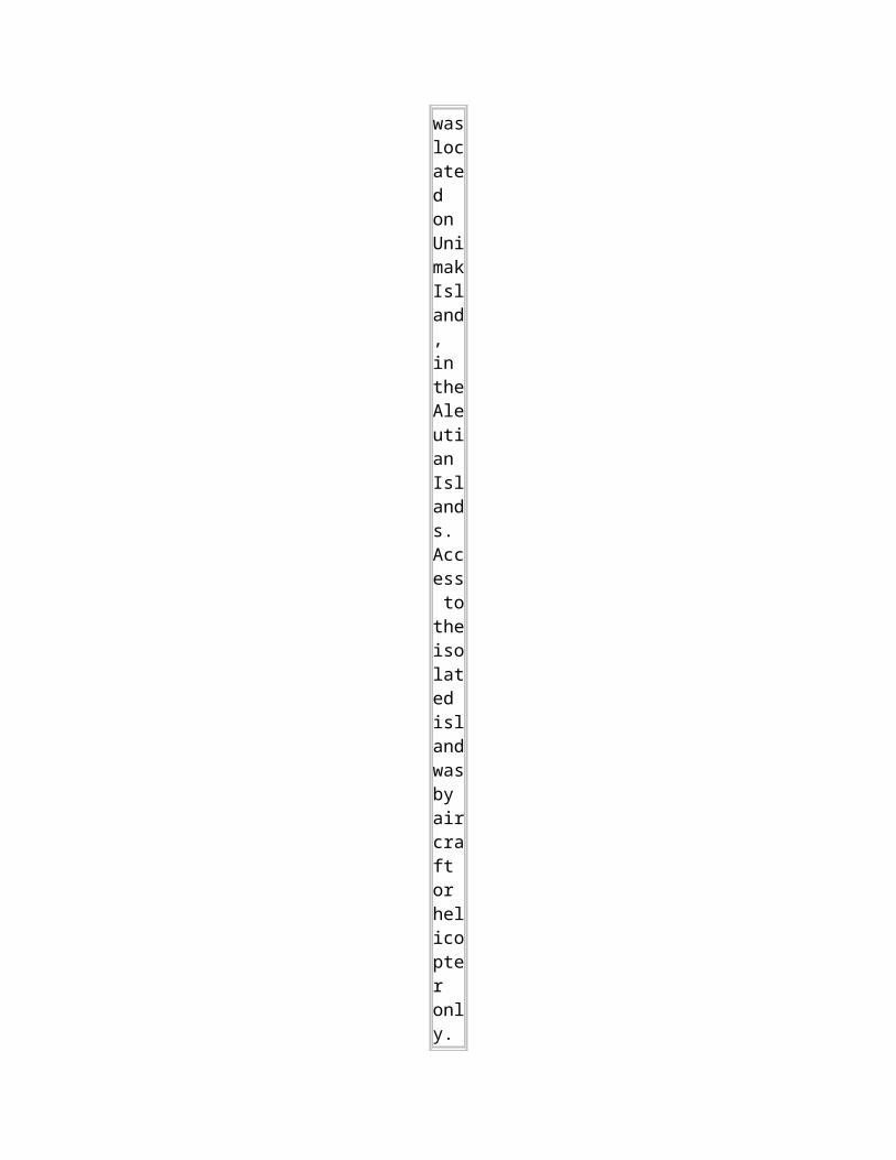
Tracks: This drawing illustrates the Dectra tracks across the Atlantic.
Coverage: Unfortunately the clarity of this chart is not the best, but it does give the reader some idea of the Dectra coverage area and the expected accuracy. Within the area of the two small ovals adjoining Gander, Newfoundland and Prestwick, Scotland, the system would provide an accuracy of 5 miles. Elsewhere, and within the confines of the large oval, the best resolution would be 10 miles.
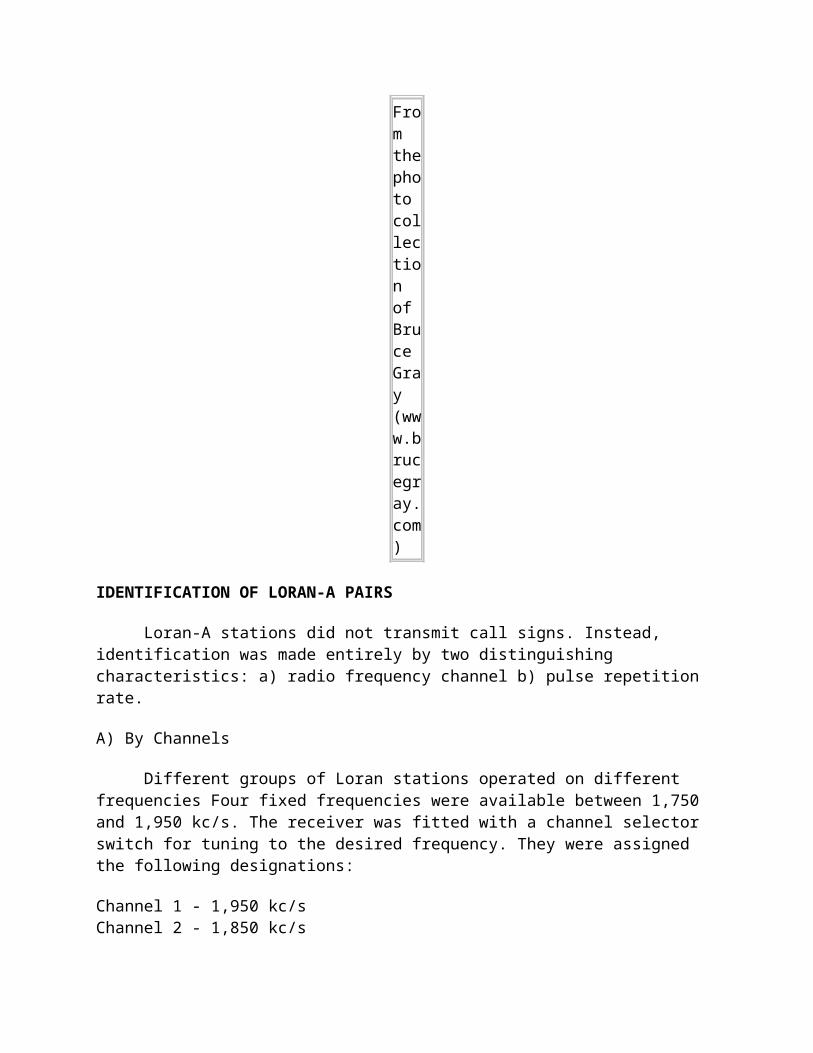
POSITION PRESENTATION
A Flight Log, mounted in the cockpit, was used for presentation, On this, ranging information would be displayed on a suitably scaled chart and tracking would be shown on a scale variable in steps from 2 miles to the inch in terminal areas and 40 miles to the inch at mid route. Normally one chart would be sufficient for a particular route so that no in-flight re-setting would have to be done. Alternatively, meter presentation was employed in those cases where it is desired to use the system primarily as tracking facility.
TEST MODE: The Decca Standard Flight Log with three decometers and a control unit arranged as a test installation on an aircraft owned by British European Airways. This photo is believed to be from the mid 1950's. Normally the Flight Log is in view of the pilot. (Photo courtesy of Meccano Magazine, March 1957).
IN USE: Mounted at the forward part of the cockpit and above the instruments was the special lightweight version of the Decca Flight Log suitable for short flights or for use in helicopters. This photo is believed to be from the mid 1950's.( Photo via Meccano Magazine, March 1957)
SUMMARY
At the time there was continuous Decca coverage down the Canadian East Coast as well as over the UK, and the scheme might have met with success had Decca been adopted for aircraft use. Dectra was discontinued in the late 1960's when inertial navigation systems became the standard airline long range navaid.
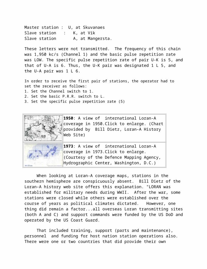
LORAN C
Loran-C, the successor to Loran-A, was originally developed to provide radionavigation service for U.S. coastal waters and was later expanded to include complete coverage of the continental U.S. as well as most of Alaska. Twenty four U.S. Loran-C stations work in partnership with Canadian and Russian stations to provide coverage in Canadian waters and in the Bering Sea. Loran-C provides better than 0.25 nautical mile (460 meters) absolute accuracy for suitably equipped users within the published areas.
Users can return to previously determined positions with an accuracy of 18 to 90 meters using Loran-C in the time difference repeatable mode. Advances in technology have allowed greater automation of Loran-C operations. New technology has allowed the United States Coast Guard to establish centralized control of the continental U.S. Loran-C system at two locations. The application of new receiver technology has improved the usability of the system. A majority of the 1.3 million Loran sets in use worldwide are for mariners. Loran-C is greatly appreciated by the US general aviation community with some 80,000 aircraft now equipped with the system.
SIGNAL CHARACTERISTICS
STATIONS
Loran-C transmitters are organized into chains of 3, 4 or 5 stations. Within a chain, one station is designated "Master" (M) while the other "Secondary" stations identified by the letters W, X, Y and Z. Different secondary designations are used depending on the number of station in a chain. This is summarized in the table below.
CONFIGURATION DESIGNATORS EXAMPLE
Master with 5 secondaries M V, W, X, Y, Z South Central U.S. 9610
Master with 4 secondaries M W, X, Y, Z Southeast U.S. 7980
Master with 3 secondaries M X, Y, Z Canadian West Coast 5990
Master with 2 secondaries M W, X Calcutta 5943
Master with 2 secondaries M X, Y East China 8390
By 1989, there were 16 Loran-C chains comprising 67 stations and transmitting on 100 kHz. In the year 2000 this had grown to 28 chains. Power levels can range from as low as 11 Kw (Bombay 6042) to as high as 1.2 megawatts (China East Sea 8390) . In Russia, a navigation system known as CHAYKA is compatible with Loran-C hence it forms part of the workwide chain. Transmitting station signal availability is greater than 99.9 percent while typically providing 99.7 percent triad availability.
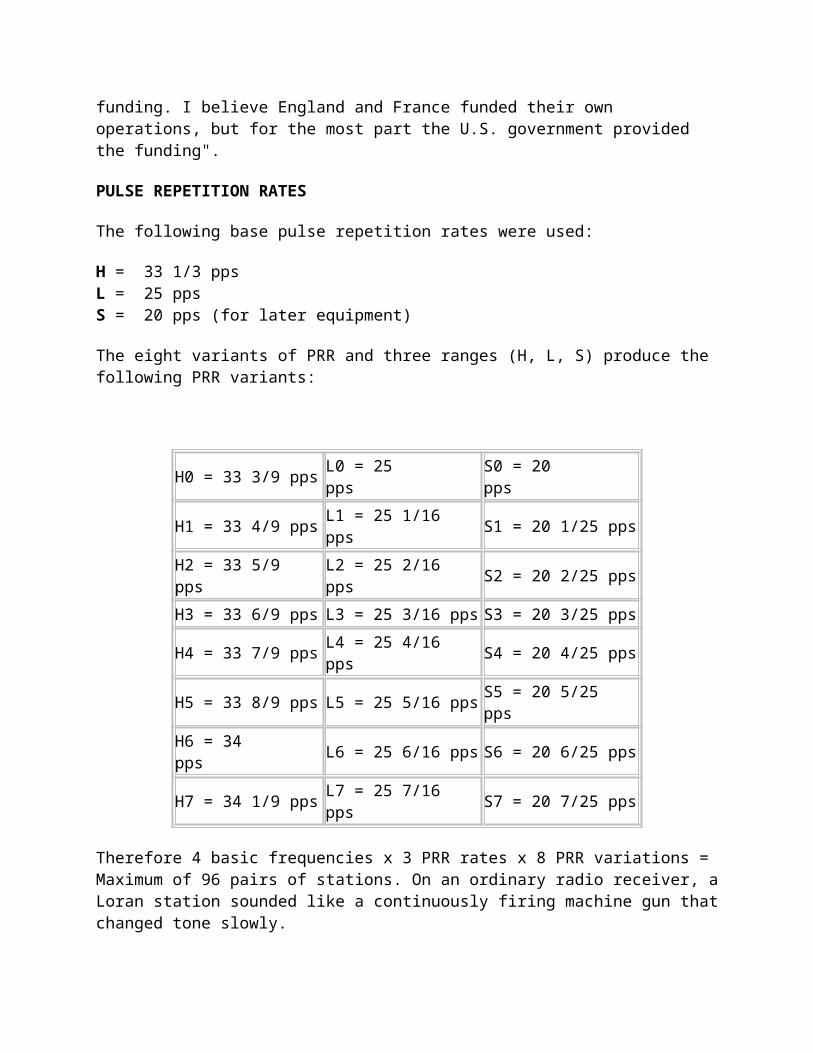
The Loran-C navigation signal is a carefully structured sequence of brief radio frequency pulses (Fig. 1a) on a carrier wave centered at 100 kHz. All secondary stations radiate pulses in bursts of eight, whereas the Master signal, for identification purposes, has an additional ninth pulse burst (Fig. 1b). The sequence of signal transmissions consists of a pulse group from the Master (M) station followed at precise time intervals by pulse groups from the secondary stations. The time interval between the reoccurrence of the Master pulse is called the Group Repetition Interval (GRI), see Fig. 1c. Each Loran-C chain has a unique GRI.
Figure 1:
Loran-C
pulse
format and sequencing
.
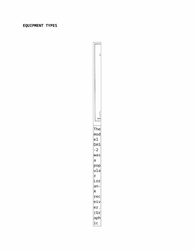
Since all Loran-C transmitters operate on the same frequency, the GRI is the key by which a receiver can identify and isolate signal groups from a specific chain. In naming the chains, the GRI is included. As an example the Great Lakes chain has a GRI of 8970. This means the time interval is 89700 microseconds. The rightmost zero is always implied and the GRI is always in multiples of 10 microseconds. In old Loran-C receivers, the operator had to actually set this number to receive the chain. In cases where the Loran signals were observed on an oscilloscope, pulses from the desired chain would be stationary while those from other chains would be drifting down the time base at varying speeds. It was in fact, the only way of positively identifying a chain, however in modern receivers, this is now done automatically.
GRI's are chosen on the basis of :
(a) Baseline lengths between master and secondaries. If the distance between the master and first secondary is say 1000 kms, the radio signal will take 33,000 microseconds to get to the slave so the GRI cannot possibly be less than that. (b) Number of slaves that have to be accomodated - they all have to have delays so that there is no possibility of them crossing over anywhere in coverage area.. (c) Geography. (d) Other nearby chains witrh consideration given to interference. (e) Skywave cross-rate interference. (f) Duty cycle of the transmitters - a faster GRI means the average power of the transmitted signal is higher so the final stage in the transmitter requires more cooling.With average baseline lengths and three slaves, the minimum GRI cannot be much less than 50,000 microseconds.
Each Loran-C pulse has an approximate dura
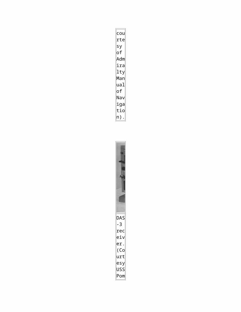
tion of 200 µs. The interval between pulses within a pulse group is 1000 µs, except for the last two pulses at the Master which have a 2000 µs interval. The graphic below
illustrates one pulse. (Graphic Courtesy of NELS)
This graphic illustrates the points on
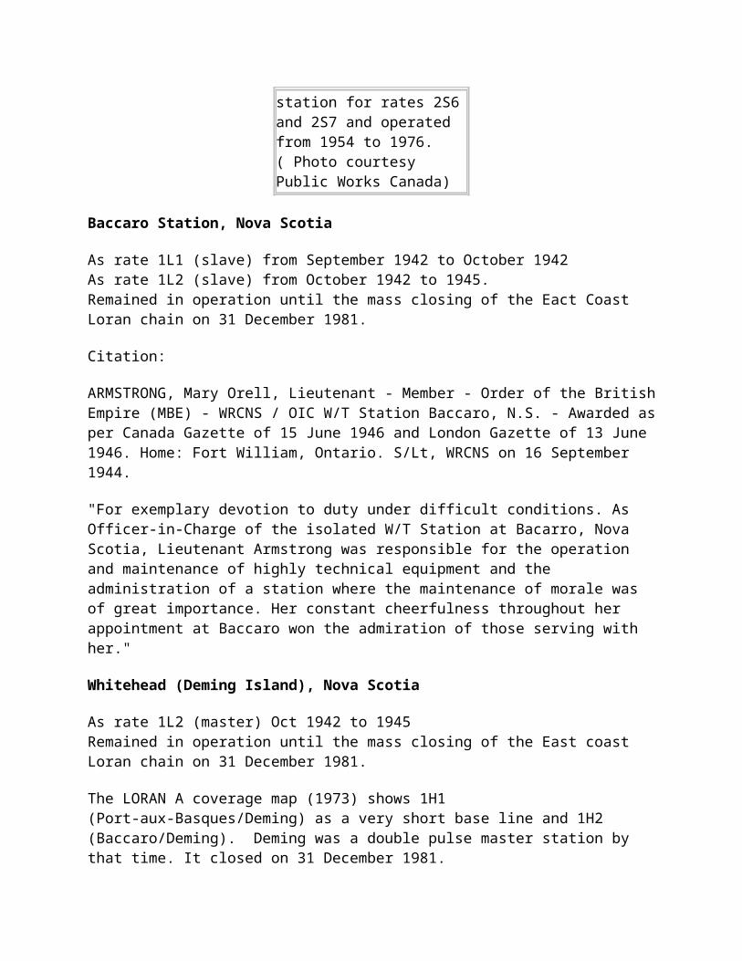
the Loran-C pulse envelope that define the start time, the time of maximum envelope power and the stop time of the pulse.(Graphic courtesy of NELS).
Two other important characteristics are associated with Loran-C signals, namely emission and coding delay. If the master station is taken as a reference, the emission delay refers to how long it takes before the secondary transmits after the Master has done so. The coding delay is a very
small correction that removes the local (near-field) discrepancy between the envelope and carrier. Both parameters are measured in microseconds and are uniquely associated with each secondary station.
BASELINES AND COVERAGE
An imaginary line drawn between the Master and each secondary station is called the baseline. The continuation of the baseline in either direction is called a baseline extension. Typical baselines are from 1200 to 1900 km (say 600 to 1000 nautical miles). Chain coverage is determined by the power transmitted from each transmitter in the chain, the distance between them and how the different transmitters are oriented in relation to each other (the geometry of the chain).
SKY WAVE REJECTION
A frequency of 100 kHz was chosen for the Loran-C carrier wave to take advantage of propagation of the stable ground wave to long distances. However, the presence of delayed sky waves, reflected from the ionosphere, cause distortions of the pulse shape and change the carrier phase within the pulses of the received signal. Not only that , the skywaves take longer to arrive at the receiver than the ground wave, so their presence complicates the computation. To avoid sky wave contamination, the Loran-C receiver selects a zero crossing of a specified carrier cycle at the front end of the pulses transmitted by master and secondary stations. Making the cycle selection early in the ground wave pulse - usually the third cycle is employed - ensures that the time interval measurement is made using the uncontaminated part of the pulse. But how is the third peak selected when the start time of the pulse is not known? To solve the problem, the receiver compares the the envelope (the rough shape) of the received pulse with a stored envelope, This process is called the "rough measurement". When the third peak is finally located, the phase of the signal can be determined. The phase of the signal can be zero or pi radians. Precise control over the pulse shape at the transmitter also ensures that the selected zero crossing can be identified reliably by the receiver.
Zero Crossin
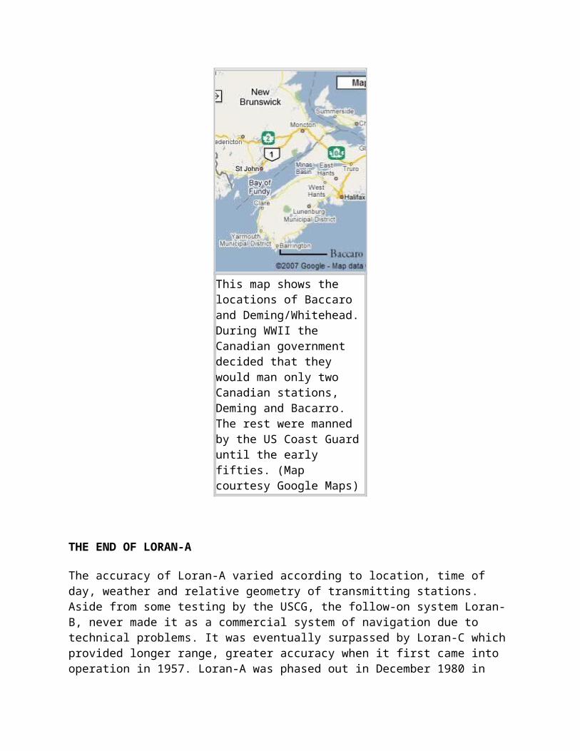
g: This diagram illustrates the third cycle in the Loran pulse. (Graphic courtesy of the USCG).
PHASE CODING
To reduce the effects of interference and noise on time difference measurements, and to assist in distinguishing between master and secondary stations, the carrier phase of selected transmitted pulses is reversed in a predetermined pattern. The pattern is shown in Fig. 2, where a minus sign indicates an inverted pulse (180° phase shift), and a plus sign means no phase shift. This pattern is repeated every two GRI's. Simply stated, phase coding determines whether the first peak in the pulse is upwards or downwards.
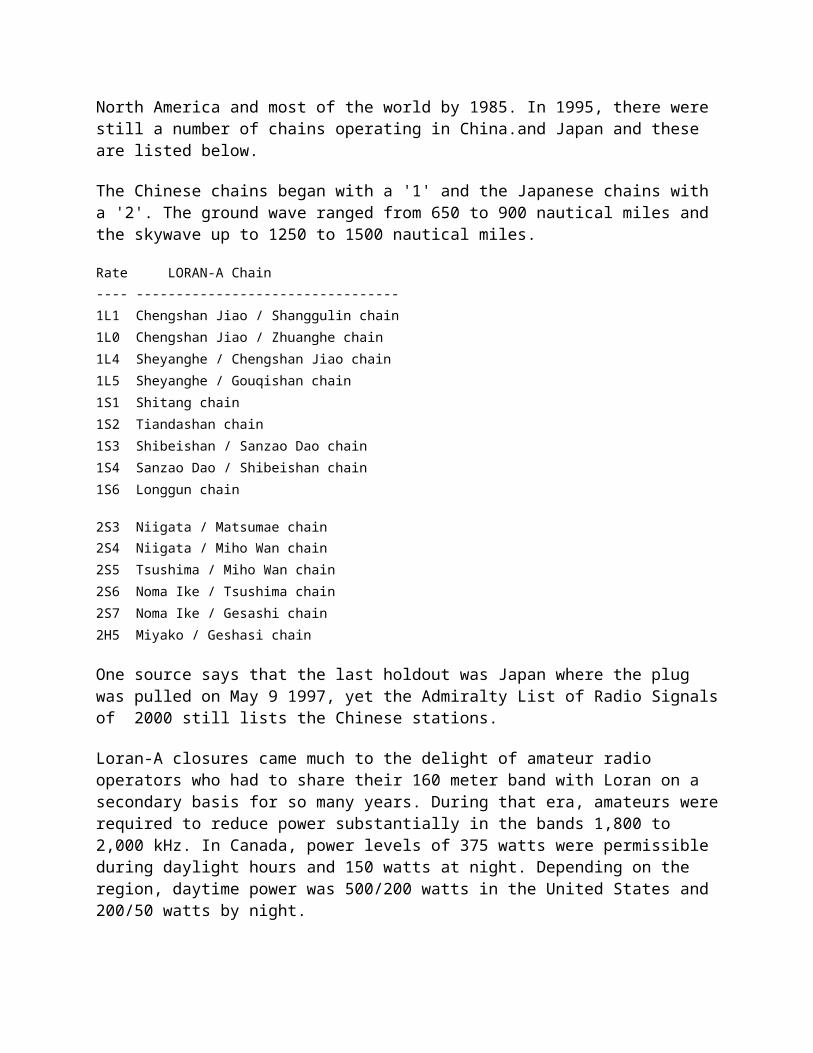
Figure 2:
Phase
Coding (Graphic by Orblet Technologie
s AB)
.
TIME DIFFERENCE MEASUREMENTS
The basic measurements made by Loran-C receivers are to determine the difference in the time-of-arrival (TD) between the master signal and the signals from each of the secondary stations of a chain. Each TD value is measured to a precision of about 0.1 microseconds (100 nanoseconds) or better. As a rule of thumb, 100 nanoseconds corresponds to about 30 metres. The principle of time difference measurements in hyperbolic mode is illustrated in Fig. 3.

Figure 3:
Time
Difference
Measuremen
ts
AUTOMATIC OPERATION
Today’s state-of-the-art, solid state Loran-C transmitters are adapted for automatic operation; that is to say all vital transmitter functions are duplicated or designed for graceful degradation so that the result of a defect is minimised.These vital functions are further monitored at the Control Centre which has the capability of initiating corrective action using data communications. As a consequence, the transmitters may be operated as unmanned stations except for caretakers.
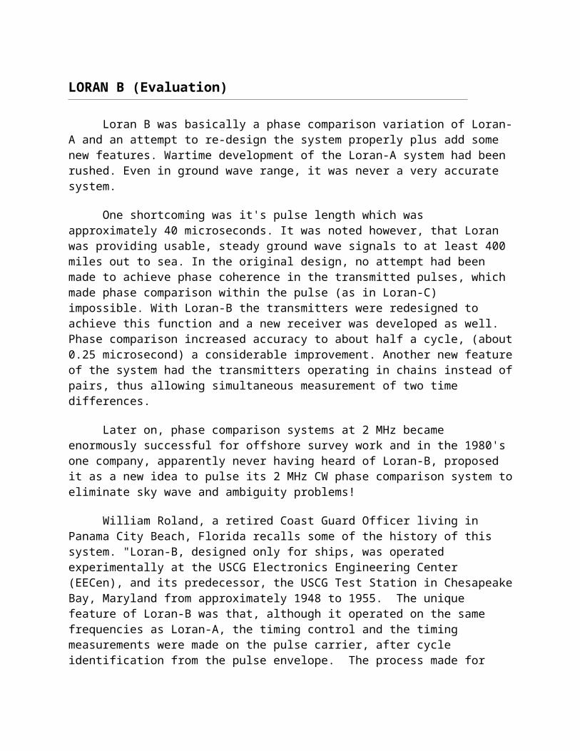
PRECISION CLOCKS
To achieve high positioning accuracy within the service area, Loran-C transmitter stations are equipped with a suite of atomic clocks which provide the timing for the transmitted Loran-C signal. On most stations these clocks are cesium frequency standards with a stability of typically 10-13, or an error of 1 second in 317,000 year. Precise navigation with Loran-C demands that the error in the timing system must not exceed a few tens of nanoseconds. For NELS it is specified that a station's clock shall not deviate by more than 30 nanoseconds from the clocks of the neighbouring stations. Achieving this precision in timing it is necessary to continuously measure the time deviation between the clocks in the system.
SAM CONTROL
There are two basic methods in use for monitoring and adjusting the clocks in Loran-C systems. The most commonly used method up to now is to measure the time difference between Loran-C signals received from a master and a secondary at a fixed location in the coverage area. Timing control includes making adjustments to the clock of the secondary station so that the measured TD is kept at a predetermined value. The measurement equipment at the fixed location is called a System Area Monitor (SAM), hence this method of timing control is referred to as "SAM control".
TOE CONTROL
In the other method for timing control, used by the Northwest European Loran-C System (NELS), there are no SAM's. Instead, arrival times of signals from adjacent transmitters are measured relative to the local clock at each transmitter station. The measurements from all stations in the system are sent by permanent data link to the control station where they are combined so that the time deviation of each transmitter's clock can be calculated. Computed adjustments are returned to the individual transmitter sites where they are used for clock synchronization. This results in a common time reference for the Time Of Emission (TOE) of the Loran-C pulses from all transmitters and is called "TOE control". The common NELS time reference is itself related to UTC using the UTC (Brest) time standard which is co-located with the NELS Control Centre at Brest, France. The NELS time reference synchronization to UTC (Brest) is maintained to within 100 ns.
TOE and SAM CONTROL COMPARED
Under TOE control, the time difference measurements over the coverage area will vary slightly with seasonal changes in the speed of ground wave propagation. With SAM control, time difference measurements made especially close to the area monitor will be very stable. TOE control thus provides better overall performance monitoring throughout the coverage area. Other advantages of TOE control over SAM control are:
* Modeling and prediction of TD variations are made easier. * Time derived from the signals is more accurate. * Better accuracy for cross-chain and master independent use.
* Better accuracy for Rho Rho navigation (circular navigation method); * No monitor sites are needed.
ADDITIONAL SECONDARY FACTOR (ASF)
A Loran-C receiver computes distances from Loran-C transmitting stations using the time of arrival measurements and the propagation velocity of the radio ground wave to determine position. Small variations in the velocity of propagation between that over sea water and over different land masses are known as the Additional Secondary Factor, or ASF. Corrections may be applied to compensate for this variation. Such corrections may improve the absolute accuracy of the Loran-C service in positions where the received Loran-C signal passes over anything but sea water on its way from transmitter to receiver. The values of ASF depend mainly on the conductivity of the earth's surface along the signal paths. Sea water has high conductivity, and the ASFs of sea water are, by definition, zero. Dry soil, mountains or ice generally have low conductivity and radio signals travel over them more slowly, giving rise to substantial ASF delays and hence degradation of absolute accuracy.
Fortunately, ASFs vary little with time, and it is possible to calibrate the Loran-C service by measuring ASF values throughout the coverage area. A program for mapping of ASF in northern Europe is the basis for the production of ASF corrections. These corrections will be distributed as electronic databases.
SERVICE INTEGRITY
Loran-C stations are constantly monitored to detect signal abnormalities which would render the system unusable for navigation. "Blink" is the prime means by which the user is notified that the transmitted Loran-C signal does not comply with the system specifications. Blink also indicates that the Control Centre cannot ensure that the signal complies with these specifications, for instance, as a result of discontinuation of data communications linking the Control Centre to the stations. Blink is a distinctive change in the group of eight Loran-C pulses that can be recognized automatically by a receiver so the user is notified instantly that the Loran-C chain blinking should not be used for navigation. Blink starts at a maximum of 60 seconds after detection of an abnormality. Automatic blink initiated within 10 seconds of a timing abnormality may be added where Loran-C is extensively used for aviation purposes.
ACCURACY
The Loran-C service will support an absolute accuracy varying from 185 meters to 463 meters (0.1 to 0.25 nautical miles), depending on where the observer is within the coverage area. Absolute accuracy defines a user's true geographic position (latitude and longitude). Repeatable accuracy is a measure of an observer's ability - by using a navigation system such as Loran-C - to return to a position visited previously using the same navigation system. Loran-C repeatable accuracy is sometimes as good as 18 meters and is usually better than 100 meters within the coverage area.
PROPAGATION ANOLOMIES
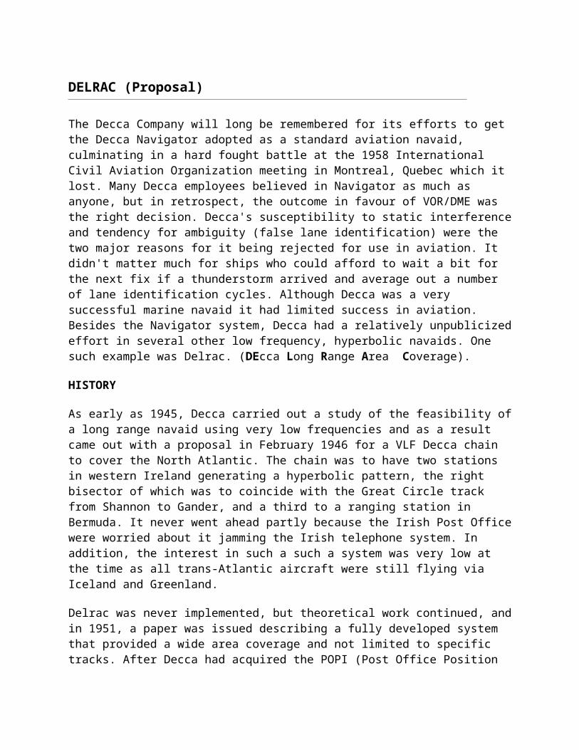
The inherent accuracy of the Loran-C system makes it suitable for many land radio location applications. However, propagation anomalies may be encountered in urban areas caused by the proximity of large man-made structures. Compensation for these anomalies is usually possible either by prior measurement or by the application of the local ASF. Substantial improvement in the accuracy of Loran-C service is technically possible by the measurement and broadcast of local corrections in a technique known as differential Loran-C (DLoran-C). This is similar to what is achieved with GPS using GPS differential corrections known as DGPS.
TIME TRANSFER STANDARD and OTHER MODES
The Loran-C system is capable of being utilized as a time transfer standard.
The HF stations WWV and WWVH (and others like CHU) suffer from variations in propagation time because of changes in the ionosphere. WWVB at 60 kHz is much better in that respect but suffered from low output power until the late 1990's. Loran-C was the best source of radio time signals for the last few decades. A number of companies built receivers that were specifically designed to be time reference receivers. It's only been in the last few years that GPS based time transfer had better performance than Loran-C. Apparently, there is a capability to send digital data on the Loran-C signal for military use. Can anyone comment on this?
LORAN-C can be utilized in different modes of operation. Most common is the hyperbolic mode. Circular mode, often referred to as Range-Range or RHO-RHO, has limited application for special users. Unique and expensive user equipment is required for RHO-RHO operation however; it only takes a fix from two stations to establish position.
TRANSMITTER STATION EQUIPMENT
Loran-C station equipment in the the U.S. West Chain 9940 Lorsta "Searchlight". This is one of several "dual rated" stations in the Loran chain.The USCG prefixes its Loran station names with Lorsta which is a contraction of the words Loran and station (Photos courtesy USCG).
DUAL RATED CHAINS
Some transmitters in a Loran chain have only one function. That means they either serve as dedicated master or dedicated secondary station in a particular chain. Many transmitters, however are dual rated, meaning that these can serve one function in one chain and yet another in a neighboring chain. For example, the Lorsta Searchlight (Nevada) facility has a transmitter which serves as the secondary (Y) station in the 9440 chain and it also serves as the secondary (W) station in the neighbouring chain 9610. Dual rating is desirable because, other things being equal, land acquisition costs and siting difficulties are reduced.
In a dual rated environment, the operations/timing room has dual timing systems which are common to one transmitter. Both timing systems operate from the same cesium frequency standard, thus helping to reduce equipment cost. There is not one but two electronic timers for each rate. For each rate, one timer is always on-line while the other serves as a standby unit.
DUAL RATES: These maps of chain 9610 (left) and 9940 (right) serve to illustrate their coverage area. The dual rated station Lorsta Searchlight (Nevada) is used as the secondary (W) in chain 9610 and secondary (Y) in chain 9440. (Graphics courtesy of USCG).
The Canadian East Coast chain 5930 has one master and three secondaries. All four stations are dual rated.
Here is an example of a current (2001), state-of-the-art solid state Loran-C transmitter. This is the Model A6500 manufactured by Megapulse Inc (Photo courtesy of Megapulse Inc).
GLOBAL COVERAGE
Coverage:
This map illustrates the global coverage of Loran-C. (Graphic courtesy of Eurofix web page).
Texas Instruments 9000 Microprocessor Controlled Loran C Receiver
The TI 9000 Loran C receiver, announced in August, 1977, was the first low cost receiver designed for small boats and for use by the novice as well as the veteran skipper. This unit, S/N 9A0662 was the 162nd production set.
The TI 9000 was microprocessor computer controlled to rapidly and automatically search, acquire and track available stations to obtain and display up to four time differences. Several configurations and circuit updates of the 9000 were built, including the TI 9900 series which provided voice information for certain programmed functions. A line of airborne receivers, TI 9100, TI 91 and TI 92 were also built, starting with the TI 9100 in early 1982. TI halted production of the Loran receivers in the first quarter of 1986 because of unprofitability. The line had become a mature technology with high assembly costs. Subcontracted assembly in Mexico could not match the Far East competition.
T.I. 9000
Loran- C
Receive
r (Photo courtesy of the Smithsonian Institution)
Antenna
for 9000
receiver. (Photo courtesy of the Smithsonian Institution)
DECCA
Decca Model 1024 Loran-C receiver. (Courtesy Decca Navigator Company)
FUTURE OF LORAN-C
In the United States, the Loran Service Unit (LSU) is the engineering center for Loran-C; NAVCEN is the operations center, and USCG HQ is the program center.
Under the 1994 U.S. Federal Radionavigation Plan, with GPS promised as better performing replacement, the Department of Transport advanced the phase-out date of Loran-C from 2015 to December 31, 2000, dealing a body blow to the system operated by the US Coast Guard. Outside the US, the Coast Guard left individual countries to decide whether to continue their own operations.
In Canada, as part of the Marine Aids Modernization program, the Canadian Coast Guard (CCG) is evaluating the impact of the proposed discontinuance of Loran-C navigation service. The objectives of the impact study are to identify the Loran-C users; to evaluate the present use of the system in relation to the introduction of new technologies such as GPS/DGPS and Electronic Chart Display and Information Systems (ECDIS); and to identify the availability of suitable alternatives to providing and funding the current service. It is believed that the demand for Loran-C will decline as new technologies, such as GPS and DGPS, become recognized as reliable and accurate navigation systems. In the Royal Canadian Navy, Loran C was fitted in all the "steamers" during its popularity but all those ships are now paid off. At this time, the system is being removed from the AOR's and the 280 Iroquois class ships.
At this time, there are 5 transmitting sites in Canada, namely Cape Race (Nfld.), Comfort Cove (Nfld.) and Fox Harbour (Labrador) on the east coast and Port Hardy (B.C.), Williams Lake (B.C.) on the west coast. In addition, there are 4 control and monitor sites at St. Anthony (Nfld.),
Williams Lake (B.C.), Montague (P.E.I), and Sandspit (B.C.). The total estimated cost of the Loran-C program in Canada is $2.229M.
A study being carried out by the Goss Gilroy company will include in-depth telephone interviews with Loran-C interest groups. Following this, a questionnaire will be specially developed and distributed nationally to marine and non-marine user groups. The study will also include eight national focus groups and a benefit cost study of possible alternatives. All of this is expected to be completed by early 2000. The CCG’s proposed discontinuance of Loran-C in Canada is not directly related to the United States (U.S.) 1994 & 96 Federal Radio Navigation Plan announcement, although coordination with the U.S. would be required.
In 1997, an independent study was conducted in the U.S. to evaluate the impact of discontinuing Loran-C. Finally, on June 29, 1998, a decision was made by FAA, USCG and OST to continue the operation of Loran-C beyond its currently planned 12/31/00 termination date. At the ICAO CNS/ATM implementation conference held in Rio de Janeiro, the FAA dropped a bombshell by announcing, contrary to all earlier assurances, that the Global Positioning System (GPS) would not be approved for sole use navigation, and would need a backup. The reason given was that the possibilities of jamming, solar events, etc., were now better understood. Excellent though GPS may be, its problem is that it is so low powered that the signal can easily be blanked out or disrupted - as demonstrated at an 1997 Moscow air show where a jammer destroyed the signal over a radius of 200 km. The notion of GPS as sole means of navigation is dead. Suitable backup systems cited are triple inertial, VOR/DME and LORAN-C.
The implications of the FAA's new position are many - ranging from the need to maintain a ground based ILS and VOR/DME/NDB navigation aids system way beyond the time scale the world had been led to expect, to the probable continued operation of LORAN-C chains. As of September 1998, the American DoT confirmed that the existing LORAN-C chains will be maintained and upgraded, at least to 2008, "in the transition period to satellite based navigation".
Linn Roth, President of the International Loran Association (1999-2000) published a white paper which underscores the need for Loran-C to be a backup for GPS for at least 15 more years. While public debate over national GPS policy appears to be moving away from GPS as a sole-means system, it is interesting to note that industry has recognized the realities of the situation and provided backups all along. For example, commercial airlines carry a number of redundant, dissimilar systems, and no major carrier has equipped even half a fleet with GPS receivers, choosing reliance on these other systems until GPS augmentation programs are clarified, implemented and proven. Telecommunication and power grid systems rely on GPS as their primary timing reference for network synchronization, but incorporate Loran receivers or Rubidium oscillators to carry over in case of GPS interruption. Although not generally understood, GPS-based car navigation systems typically integrate differential wheel counters and digital map matching technologies in order to compensate for GPS’ poor penetration into urban environments.
From a physical perspective, Loran and GPS have very different characteristics. In essence they complement each other: ground vs. satellite based, low vs. high frequency, high signal level vs. low signal level. Consequently they do not suffer from the same modes of failure so they should
in theory, never fail simultaneously. Loran or GPS will be always be available to provide better performance under conditions where one system might be compromised. Loran’s wavelength and signal strength enable it to penetrate into areas where GPS has difficulty because of line-of-sight blockage as in urban or forested situations. Loran can even penetrate some buildings. In fact, the Defense Advanced Research Project Agency (DARPA) has explored combined receivers that could be used to locate troops in urban environments. Loran penetration into cities and its ability to provide an indefinite backup to GPS in timing applications are two additional advantages Loran provides in telecommunication applications.
Within Europe, the European Union promotes the development of Loran-C chains under the auspices of NELS (Northwest European Loran-C System). The ownership of each of the facilities within NELS is vested in the state on whose territory the facility is located. Superior direction of the system is exercised by a Steering Committee where all members are represented. A Coordinating Agency is appointed for implementation of directives given by the Steering Committee and to coordinate the establishment and operation of the system. Norway accepts the role as Coordinating Agency.
The most recent draft European Radio Navigation Plan (ERNP) and European Commission report (31/10/96) includes Loran-C as part of the desired system mix in marine, land transport and aviation to at least the year 2020. In north-west Europe, where Loran is used primarily for air to land and maritime navigation, and where the GPS/DoT lobby was not so strong, Denmark, France, Germany, Ireland, Norway and the Netherlands teamed up to form NELS with the expectation to modernize existing transmitters and establish some new ones. NELS, up and running since April 1998, with the exception of the delayed Irish station, may be enlarged to include two Italian stations to extend coverage in the Mediterranean. This expansion would include a linkup with the Russian Chayka system, which can also be received by the modern Loran receivers, in the western Arctic, the Baltic (Belarus) and the Crimea.
It appears on the cards that the DoT will extend and modernize the Loran-C system as an economical backup to GPS, at least until 2008, or until the arrival of a failsafe GNSS-2, under international control.
ENHANCED LORAN-C DATA CHANNEL PROJECT
Research efforts are underway to increase the data carrying capability of the Loran-C Data Channel using combinations of previously developed modulation techniques. The purpose of this is to provide a unidirectional communications information for Global Positioning System (GPS) integrity and potentially for GPS correction data.
Several different methods are under evaluation: Pulse-Position Modulation (PPM), Supernumerary Interpulse Modulation (SIM), Intrapulse Frequency Modulation (IFM), and/or Hybrid combinations of these. These are beyond the scope of this document so they will not be explained here.
In addition to the above, the FAA is assessing Loran developments in four key areas:
1) Development of a Loran H-field antenna suitable for aircraft installation 2) Development of an RTCA DO-194/FAA TSO-C60b compliant Digital Signal Processing (DSP) Loran receiver. 3) Development of enhanced Loran communications capability for GPS integrity and potentially for GPS correction data. 4) Development of a hybrid GPS/Loran receiver architecture.
The Enhanced Loran-C Data Channel project concentrates on the third of these four objectives. Existing or proposed equipment may not be capable of actual transmissions of all of these modulation formats. Stanford University, the USCGA, and the LSU are cooperating to evaluate viable data formats and technology to permit the modulation and demodulation of data messages transmitted via modulation of Loran-C signal pulse(s).
The basic GPS service fails to meet the accuracy (the difference between the measured position at any given time to the actual or true position), availability (the ability of a system to be used for navigation whenever it is needed by the users, and its ability to provide that service throughout a flight operation), and integrity (the ability of a system to provide timely warnings to users or to shut itself down when it should not be used for navigation) requirements critical to safety of flight.
In order to meet these requirements, the FAA is developing the Wide Area Augmentation System or WAAS. WAAS is a safety-critical navigation system that will provide a quality of positioning information never before available to the aviation community. It is what the name implies, a geographically expansive augmentation to the basic GPS service. The WAAS improves the accuracy, integrity, and availability of the basic GPS signals. This system will allow GPS to be used as a primary means of navigation for en route travel and non-precision approaches in the U.S., as well as for Category I approaches to selected airports throughout the nation. The wide area of coverage for this system includes the entire United States and some outlying areas such as Canada and Mexico.
The WAAS signal has enough capacity to carry both the differential corrections and the integrity data required to augment GPS. Loran-C could also provide a land based data channel supplement to Space Based Augmentation Systems (SBAS), like WAAS. The inherent integrity and robustness of the Loran-C signal may obviate the need for some error correction overhead, thereby reducing the data rate required for transmission of WAAS messages using Loran-C to an achievable level. Loran-C also provides a readily available, extremely reliable, strong (+6 to +10 dB SNR) signal over all of the Contiguous United States and Alaska.
Besides supplementing SBAS, other potential uses of the Loran-C data link are possible. It could be used for differential Global Positioning System, (DGPS) corrections, differential Global Navigation Satellite System (DGNSS) corrections, contingency control of the Loran-C system during loss of landline communications, and differential Loran-C corrections.
Of specific concern is the ability to transmit WAAS messages. In the past, the USCG has accomplished data transmissions on Loran-C using Pulse-Dropping techniques, Polyphase Communications (PM) Modulation, Clarinet Pilgrim (CP), and Two-Pulse Communications (TPC). Currently, the EUROFIX (possibly known as Loran Comm or Lorsat) system is correctly transmitting DGPS correction information in Europe. Unfortunately, none of these techniques provide enough bandwidth to transmit the WAAS message format. The fundamental problem is to develop a Loran-C signal data channel with enough bandwidth to satisfy WAAS requirements. If we can meet WAAS bandwidth requirements, other less bandwidth hungry applications are easily satisfied.
The entire white paper on which this summary is based used to be available at: http://www.uscg.mil/hq/lsu/wepage/papers/Bonn_LSU_final.htm . It is no longer posted.
LATEST NEWS ABOUT LORAN-C
NELS
November 2005 - Recently the NELS (Northwest European Loran-C System) organization announced that NELS will be discontinued on January 1st, 2006. In December further info will be provided about the future of the other Loran-C stations in Europe.
The Norwegian Government has decided to close down the Norwegian Loran-C stations Berlevag, Bo,Vaerlandet and Jan Mayen on 5-1-2006 at 1200 UTC.
Both the German station at Sylt and the Danish station at Ejde will shut down on 1-1-2006 at 0000 UTC. (quote from Worldwide Utility News)
December 2005 - Extended operation of Loran-C at the Norwegian stations
The Government will continue the operation of the four Norwegian Loran-C stations, Værlandet (Askvoll Municipality in Sogn og Fjordane), Bø in Vesterålen (Nordland), Berlevåg (Finnmark), and Jan Mayen, in 2006. The reason for this is the renewed interest in this terrestrial navigation system in Europe. (09.12.05)
Denmark has decided to continue the operation of the Danish Loran-C station at Ejde.
Germany’s decision to discontinue the operation of its LORAN C station Sylt remains unchanged. However, the station Sylt will not, as originally planned, be switched off on 3 January 2006, but the operation will be continued until the measures required for the conversion of the time synchronization have been carried out. It is expected that these measures will take about 4 to 5 weeks. It cannot yet be predicted whether the station Sylt will be reactivated at a later time in a different provider organization. This depends on whether it will be possible to find a binding and sustainable new concept for LORAN C applying to all of Europe.
Kirsten Ullbæk Selvig Chairman NELS Steeringv Committee (Source: NELS web site)
LORAN-C Data Channel (LDC) 9th Channel Testing Commences
This extract is taken from the USCG Loran-C web page.
"LORAN-C Data Channel testing is part of the on-going effort between the Federal Aviation Administration and the U.S. Coast Guard to modernize the LORAN-C system. The LORAN Data Channel (LDC) will provide information using pulse position modulation of the broadcast
signal. The proposed pulse position modulation would be used to broadcast up to sixteen message types including but not limited to station identification, absolute time, early skywave warnings, and differential LORAN correction messages.
The proposed method will use an additional pulse added one thousand microseconds after the eighth pulse on a secondary transmitting station and between the current eighth and ninth pulses on Master.The FAA and Coast Guard began conducting LDC on-air tests in July of 2005. The test broadcast will use pulse position modulation of a ninth pulse added one thousand microseconds after the standard pulse group as described above. Throughout the test period the signal will meet all service performance parameters published in the 1994 specification of the LORAN-C Signal. Users should not experience any tracking errors or service interference from this test broadcast. Users will be notified through Notice to Mariners and Notice to Airmen of any changes to the test schedule and when the testing is completed.
Initial testing was conducted with the LORAN Support Unit in Wildwood, NJ broadcasting the LDC information on 9960-T. Phase 1 of the testing involved broadcasting from LORAN Station Jupiter, FL (7980-Y). Phase 2 added the LDC capabilities to LORAN Station Las Cruces (9610-X) and testing was conducted from 1510Z on 27 Oct 2005 to 0126Z on 07 Nov 2005. LORAN Station Seneca, NY (8970-X) began broadcasting the LDC at 1500Z on 21 Dec 2005. LORAN Station Las Cruces, NM will being broadcasting LDC continuously beginning on 01 Apr 2006".
Each Loran station will initially transmit the basic Station Identification/Time message only with exception of Loran Station Seneca. Loran Station Seneca will also broadcast differential LORAN corrections for additional research. Each transmitted message will include a “test mode” bit to warn users that the information in the message is for research ONLY. As testing continues, there is a high probability of incorporating additional messages. Each new message will have an indicator that it is for testing purposes only".
RADUX
After the low frequency Loran trials of 1945 and the realization that pulse-envelope matching at low frequencies was not sufficiently accurate to be useful (in spite of which several companies were still producing envelope matching Loran-C receivers as late as 1980!), it was decided to try superimposing a low frequency modulation at around 200 Hz and use that for timing and possible resolution of the cyclic ambiguities at 100 kHz. Several years of experimentation resulted in the realization that it was not going to work successfully, but the results indicated that the timing obtained from this modulation was probably good enough to resolve the ambiguities of much lower frequencies of, for instance, 10 kHz. Accordingly, a composite system was designed which radiated a 40 kHz signal modulated at 200 Hz and having bursts of 10 kHz superimposed. The 40 kHz supplied the accuracy, the 10 kHz resolved the 40 kHz ambiguities, and the 200 Hz resolved the 10 kHz ambiguities. It was called Radux-Omega, but it was unsuccessful because the range of the 10 kHz signal greatly exceeded that of the 40 kHz, 'while the relatively short baselines needed at 40 kHz spoiled the possible geometric accuracy of 10 kHz at long ranges.
LORAN D and F
LORAN-D was a short range, high accuracy, low power, tactical system designed for use as a bombing aid by the United States Air Force. It used "portable" transmitters and much shorter baselines than Loran- C, plus a sixteen pulse transmission instead of eight. Loran-D modified the Loran-C pulse pattern by interleaving an additional 8 pulses after each pulse of the current Loran-C pulse pattern. To interleave the additional pulses within the standard group interval, Loran-D used a modulation scheme known as Supernumary Interpulse Modulation (SIM). The additional interleaved additional pulses were coded in a pattern to which the normal Loran-C receiver was non-responsive. Thus conventional Loran-C receivers designed to receive only the 8-pulse Loran-C pattern operated on the imbedded Loran-C portion of the Loran-D signal.
In standard Loran-C, the pulses of a Loran group are spaced 1000 uS apart for all Secondaries. The Master's pulse spacing is the same for the first 8 pulses. Having an additional 9th pulse located 2000 uS after the 8th pulse identifies the Master station. The most obvious spacing to interleave additional pulses between the standard Loran-C pulses is to use the previous Loran-D format. In Loran-D the spacing was 500 uS apart. The original Loran-D pulses peaked at 80 uS, with the standard sampling point located at 60 uS. Later, Loran-D pulses were transmitted identically to Loran-C. The system was used for several war exercises in Europe in the 1960's and later. One station was temporarily erected in the UK.
LORAN-F - At the same time that the U.S. Air Force was developing Loran-D, Motorola experimented with the Multi-User Tactical Navigation Systems (MUTNS), a continuously pulsed pseudorandom coded low frequency navigation system used for drone control. It was
sometimes referred to as Loran-F in proposals but this was not an official designator. Loran-D came out ahead during system evaluations, therefore no further work was done on MUTNS.
OMEGA
The OMEGA radionavigation system, developed by the United States Navy for military aviation users, was approved for full implementation in 1968 and promised a true worldwide oceanic coverage capability and the ability to achieve a four mile accuracy when fixing a position. Initially, the system was to be used for navigating nuclear bombers across the North Pole to Russia. Later, it was found useful for submarines.
When the eight station chain became operational, day to day operations were managed by the United States Coast Guard in partnership with Argentina, Norway, Liberia, France, Japan and Australia. Coast Guard personnel operated two U.S. stations - one in LaMoure, North Dakota and the other in Haiku, Hawaii. OMEGA employed hyperbolic radionavigation techniques and the chain operated in the VLF portion of the spectrum between 10 to 14 kHz. Near its end, it evolved into a system used primarily by the civil community. By receiving signals from three stations, am Omega receiver could locate a position to within 4 nm using the principle of phase comparison of signals. In the Royal Canadian Navy, the OMEGA system was used in the AOR, 280 and Halifax class ships.
HISTORY
John Alvin Pierce, the "Father of Omega," first proposed the use of continuous wave modulation of VLF signals for navigation purposes in the 1940's. Working at the Radiation Laboratory at the Massachusetts Institute of Technology, he proved the viability of measuring the phase difference of radio signals to compute a location solution. Pierce originally called this system RADUX. After experimenting with various frequencies, he settled on a phase stable, 10 kHz transmission in the 1950's. Thinking this frequency was the far end of the radio spectrum Pierce dubbed the transmission "Omega," for the last letter of the Greek alphabet.
Radux-Omega showed the possibilities of very-low-frequency propagation, but there were fears about ambiguity errors if a single low frequency were used on its own. In the 1950's two new factors appeared - the inertial navigation system (INS) and the great increase in electronic system reliability following the introduction of the transistor. INS was not all that accurate, particularly in ships, where it had to run for days on end without correction, but it could certainly carry over short losses of signal and resolve any cycle slippage that might have occurred, while better reliability meant that such outages were far less likely anyway.
Thus, ambiguities might be much less of a problem than thought, and the development of a single frequency system began to seem feasible. The 40 kHz of Radux was dropped and a new system using transmitters in California and Hawaii was set up, transmitting at 12.5 kHz. They provided good results and two further transmitters were added in Panama and the Post Office station at Criggion, North Wales. All these stations ran on their own time standards, the development by Dr L. Essen of the National Physical Laboratory. This new type of extremely
stable crystal oscillator, named after him, made this progress possible. Later, Dr Essen also built the first cesium beam atomic resonator.
These experiments continued throughout the 1950's and provided a great deal of data on propagation characteristics. Nothing that was found discouraged the idea of a navaid operating at low frequencies. In 1963, an Omega Implementation Committee (OIC) was formed chaired by Prof. Pierce and consisting of most of those who had been concerned with the earlier experiments. They were charged with designing the new navaid and, on the basis of their experiments, took the decisions about how Omega would work - the choice of frequencies, location of transmitters, power levels, etc. Originally it was calculated that a 10 KW power level from each transmitter would prove more than sufficient for reliable reception. Due to the high cost of constructing VLF antennas (Omega antenna towers were more than 1,200 feet in height), the first experimental transmissions were actually existing VLF communications stations that were modified for Omega transmissions. This committee always denied later that the Decca work on Delrac, disclosed 9 years earlier, had had any effect on their deliberations, but it was interesting that they chose identical frequencies and other characteristics.
Over 31 possible transmitting sites were considered. Eventually, eight locations were established as permanent transmitting stations. The Bratland, Norway station (near the Arctic Circle) and the Haiku Valley station on Oahu, Hawaii, originally experimental stations, were among the first in the system. In 1968, the U.S. Navy authorized full scale implementation of the Omega System based on the OIC report. Responsibility for the operation was transferred from the U.S.Navy to the U.S. Coast Guard in 1971, under the terms of title 14, USC 82. The Coast Guard created a new command, the Omega Navigation System Operations Detail (ONSOD) to operate the system. ONSOD control of the synchronization of the system was perfected while the Navy Project Office finished the task of constructing the stations. As construction of the final six stations proceeded through the 1970's, ONSOD assumed the duties of engineering maintenance for those stations as they were declared operational. Eventually, eight permanent stations located in Bratland, Norway; Paynesville, Liberia; Kaneohe, Hawaii, US; La Moure, North Dakota, US; Plaine Chabrier, La Reunion, France (Indian Ocean); Golfo Nuevo, Chubut, Argentina; Woodside, Victoria, Australia; and Shushi-Wan, Tsushima Island, Japan were completed.
Separate bilateral agreements were negotiated between the U.S. and the six partner nations. ONSOD, later the Omega Navigation System Center (ONCEN), was named the Operational Commander (OPCON) with each partner nation maintaining responsibility for administrative control (ADCON). The U.S. owned and maintained all the Omega related equipment at each station. The host nation provided personnel, funding and non-Omega support for the station. Partner nation crews came from military and civilian sources. The Argentine and French stations were crewed by both military and civilian members of their respective Navies; the Japanese station was crewed by uniformed members of the Japanese Maritime Safety Agency, while the Australian station were staffed by civilian employees of the Maritime Safety Agency (equivalents of the U.S. Coast Guard); and the Liberian and Norwegian stations were crewed by civilian government employees. It took a tremendous effort, on the part of Team Coast Guard, to provide the system with world class support. The organizations involved in this unique international system included Commandant (G-OPN-3); CG Navigation Center (NAVCEN), the current OPCON; Engineering Logistics Center (ELC) Baltimore; Electronics
Engineering Center (EECEN); Civil Engineering Unit (CEU) Cleveland; Civil Engineering Unit (CEU) Honolulu; CG Finance Center (FMCEM, Chesapeake, VA; the Eighth Coast Guard District, New Orleans, LA; and the Fourteenth Coast Guard District, Honolulu, Hawaii.
Before OMEGA could even be inaugurated, it invoked litigation against the United States government as the Decca Navigator Company of London, England had proposed a very similar system many years earlier and called it DELRAC. In 1962, what eventually became the OMEGA system appeared in a U.S. proposal to International Civil Aviation Organization using the title "DELRAC/OMEGA" although it later defaulted to plain OMEGA. The technical similarity between OMEGA and DELRAC was obvious and there was considerable bad feeling at Decca that they had not received due recognition of their much earlier efforts. Decca eventually sued the U.S. Government in 1976 for infringement of DELRAC patents and were awarded $44,000,000 damages. The U.S. never claimed OMEGA was a military navaid in the court case. By then, they didn't really need it for either aircraft or submarines, having developed inertial navigation systems. It had only implemented OMEGA world-wide by claiming it was a civilian navaid.
It was not the first time Decca had sued the U.S. Government over a navaid - they had done so in 1967 over Loran-C, and won the case there as well. Unfortunately for Decca, the Americans claimed Loran-C was a military system necessary for "national security" and did not have to pay up even though found guilty by a court of law. It's strange that the same argument was not raised in the case of OMEGA.
Omega achieved full eight station implementation in 1983 and was used by several airlines flying long range routes over water as well as by military forces. Towards the end of it's service life, the Omega system was upgraded with new timing and control equipment; Paynesville, Liberia being the last station to be upgraded in the Spring of 1996. Since the original equipment had been designed in the 1960's, certain critical components had become obsolete and could no longer be procured for replacement purposes. With an initial termination date set for the year 2005 or longer, this upgrade program had to be executed to ensure that the system continued full and reliable operation in the short term.
John (Jack) A. Pierce, who retired from a position as a senior research fellow at Harvard University, Cambridge, Mass. was awarded the Medal For Engineering Excellence in 1990 for the "design , teaching and advocacy of radio propagation, navigation and timing which led to the development of Loran, Loran C and Omega." In 1941, Pierce began working at the Massachusetts Institute of Technology's Radiation Laboratory which was testing the United States' first hyperbolic radio aid to navigation called Loran. It inaugurated in October 1942. Later work produced Loran C which operated at a lower frequency of 100 kHz. After WWII, he was appointed senior research fellow in applied physics at Harvard and from 1950 to 1974 did work on low
frequency navigation aids that lead to Omega. Among his many awards are a 1948 Presidential Certificate of Merit and the 1953 Morris Liebmann Prize of the Institute of Radio Engineers. He earned a BA in physics from Harvard while an assistant at the University's Cruft Laboratory. (Photo and copy courtesy IEEE Spectrum, August 1990)
Herbert Rideout, an engineer who worked on the development of long range radionavigation and communications at Pickard & Burns, recalls some of the early research. "Jack Pierce worked at Cruft Laboratory, Harvard University. Working for the university was considered prestigious , however the wages paid were low, so engineers associated with the radionavigation program usually worked for commercial companies who paid prevailing wages . One of those companies was Pickard & Burns, Needham MA which was under contract with the US Navy. We were closely associated with Jack and were in constant daily contact. We were able to accomplish whatever Cruft Laboratory could not do such as designing and fabricating prototype equipment. (Draco equipment, described further in this passage, fell into this class). My direct boss at Pickard & Burns was Dr. Richard H. Woodward, a graduate of Harvard and during WWII, worked along side Jack Pierce at the M.I.T. Radiation Laboratory developing Loran. Richard was one of the authors of "Loran" Volume 4 of the Radiation Laboratory Series. Pickard & Burns was a small company, having about 20 engineers on staff but we did other work besides radionavigation. As an engineer, I occasionally skipped around to other jobs, however Jack liked me and when I went on my trip aboard the vessel USS Compass Island to the Mediterranean, he said I brought back the best and most accurate data he had ever received, so from then on I belonged to Jack. The Compass Island was a US Navy research vessel stationed at the Navy Yard in New York City.
When the Compass Island departed New York, she was packed several different navigation systems which were being evaluated by the US Navy. At that time, the Navy was interested in testing out any navigation system that might be suitable for submarines. One of
them, from Cornell University, measured gravity. Since the force of gravity is never the same in any two places on earth, measuring it would permit position to be determined. A second system, SINS (Ships Inertial Navigation System) was North American Aviation's inertial navigation system. The third system from Reeves Kodak used some type of celestial based system to fix position. Lastly, there was Draco, which was intended to be a worldwide VLF hyperbolic radionavigation system. It was the brain child of John Pierce with Pickard & Burns supporting him. That system was named Draco after the constellation Draco but I do not know who gave it that name.
During the voyage, a formal Draco test program was followed which would investigate these specific areas:
* Field intensity and noise in the VLF spectrum. * Draco navigation capability. * Reception of communication signals with a Draco receiver having a 100 cycle bandwidth1. * Reception of communication signals with a Draco receiver having a special 20 cycle filter1.. * Reception of special phase shift keyed signals with a Draco receiver.
Two AN/URM-6 (14 kHz - 250 kHz) field intensity meters, one narrow bandwidth filter for the Draco receiver-indicator. and three magnetic tape recorders had been installed on the Compass Island during the first week in March 1958. An electronic antenna coupler was also installed so two URM-6 units could be attached to the ship's VLF whip antenna. Both of the field intensity meters were calibrated by the Dinger shield injection method and the effective height of the antenna was determined. Once all the equipment was installed and pretested, a preliminary cruise was scheduled from March 8 to 11, to check the full operation of the gear. During this trip it was found that the noise in the antenna coupler was too high so the URM-6 equipment was connected directly to the whip antenna thus bypassing the antenna coupler.
Once everything was operating to expectations, the ship departed New York City on 13 March and reached the Mediterranean on 23 March taking up position at 17 degrees East longitude. After cruising for 18 days (including a 3 day stopover at Palma, Spain) and taking measurements, it was time to depart. On the 9th of April the Compass Island left the Med returning to New York on April 17. The tests were very promising. Field intensity and Draco measurements were recorded using three VLF transmitter stations; NSS (15.5 kHz) at Annapolis, Maryland; NLK (18.6 kHz) at Jim Creek. Washington; and GBZ (19.6 kHz) at Criggion, Wales.
Besides being designed for hyperbolic navigation, Draco was being proposed for use as a secret, one-way communications system for submarines. It worked like this: VLF transmitters NLK at Jim Creek, Washington State, and NSS Annapolis, MD had their individual frequencies stabilized to very accurate levels - below that of one cycle. To an astute observer it seemed they drifted at a random rate. The drift was introduced by using mechanical cams which drove servo motors which in turn introduced a precise known drift rate of less than one cycle. At the receiving end, Draco consisted of rack mounted equipment comprising of two receivers, a phase comparator and a stabilized frequency reference all designed by Pickard & Burns. Received VLF signals from NLK and NSS were then fed into the phase comparator and in turn compared to a highly accurate oscillator. The difference or output representing the drift rate of the VLF
transmitted signals was represented by a voltage - the faster the drift the larger the voltage. The output voltage drove servo motors in a mechanical device that in turn drove other servos which gave a DC output voltage corresponding to the drift rate. This voltage was used to drive Esterline Angus chart recorders.
Uncorrected, the line on the chart would go from left to right representing the drift but when mechanical cams were installed which were the reverse of those in the transmitter we would see a straight line down the center representing zero phase shift in the transmitted signal. At predetermined times we would have our engineers at the transmitting sites introduce different drift rates and these would show up at our receive end as a lower or higher chart reading. It was these deviations that were proposed for communications since submarines could receive these signals without surfacing. In one test, the phase of the signals from Jim Creek were shifted 3 times during a period of 7 minutes to produce the letter 'S' in Morse code. These special transmissions were repeated once an hour for several days during the tests in the Med. Since the Draco equipment responds to shifts of phase, it was easy to read the strip recordings produced by the special transmissions.
Before leaving on the trip I asked Pierce how often he wanted the equipment calibrated and he said every 4 hours around the clock for the whole six week trip. This became somewhat complicated since it took two hours to calibrate everything. Aboard ship, I shared a cabin with one of the officers and my getting out of bed every two hours in the night did upset him a bit but even worse for me. Because I was a civilian, I was considered the junior officer and had to sleep in the upper bunk which had a ventilating duct four inches above my head. It was then that I discovered whenever I turned over during the night I automatically lifted my head five inches!
After the trip, the Cornell and Reeves-Kodak systems were never to be seen again. In August 1958, Jack Pierce and Dick Woodward prepared a technical report on the operation of the Draco equipment . The measurements showed that the average field intensity of the signals from station NLK at Jim Creek in Washington varied from roughly 30 microvolts per meter during the day to 100 to 200 microvolts per meter at night as observed in the Western Mediterranean Sea at a range of about 6,000 nautical miles.
The corresponding signal from station NSS at Annapolis, Maryland, varied from 300 microvolts per meter during the day to nearly 1.000 microvolts per meter at night in the same area at a range of about 5,000 nautical miles. These observations are in reasonable agreement with predictions based on the Pierce empirical formula for VLF propagation. But the observed signals from Jim Creek were several decibels weaker than the predictions. Presumably the losses were at caused at reflection points where the ground had poor conductivity.
The average noise level in the Western Mediterranean Sea varied from about 30 microvolts per meter at 0800 hours GMT to about 90 microvolts per meter at 1500 hours GMT. These observations were made in the springtime and, of course, higher values would be expected during the winter. It was difficult to analyze some of the results obtained from the Draco navigation equipment because station NSS was out of sync most of the time. However, the errors in the navigator's fixes were comparable with the errors in the Draco system. The consistency of the Draco observations indicate that the Draco errors rarely exceeded a mile or two in the
Mediterranean area. Comparison of the qualities of signals from NLK and NSS as received with the Draco and the Model AN/SRR11 receivers indicated that the Draco receiver was equivalent in performance to the latter.
It was therefore concluded that the Draco equipment could be used for communication as well as navigation. No significant improvement in performance was obtained by the introduction of a 20-cycle filter in the Draco receiver. The Draco strip chart recordings of special phase-shift keyed transmissions from Jim Creek demonstrated that simple messages could be transmitted reliably at a range of at least 6,000 nautical miles. Presumably such simple messages could be recorded and read at the same range (6,000 nautical miles) and depth (20 feet) under sea water as can Draco signals.
After I completed my work on the Draco project, I began to realize my interests weren't in the field of radionavigation so in 1959 I came west to work for North American Aviation. Soon I designed some equipment for the McDonald F-4 aircraft which made the company a great deal of money so I remained with them as a Project Manager. Jack Pierce retired to Weare, NH and died there in 1996 at the age of 88. As of 2005, Richard Woodward is living in Cape Cod, MA.".
Although Draco never became a radionavigation system in its own right, measurements made during its development may have been applied to Omega or into other submarine communication systems.
(
Cover of P& B Inc. product brochure from 1957. The company was founded in 1945 and later became a subsidiary of the Gorham Corp. in 1960 In 1964, P&B was auctioned off and purchased by LTV Corp . By 1970, Cardwell Condenser Co. of New York purchased P&B from LTV. After that P&B slipped into oblivion. (Brochure provided by Herbert Rideout)
This is just some of the equipment produced by P & B Inc around 1957. (Brochure provided by Herbert Rideout)
This is the certificate presented to personnel who participated in the Draco and SINS evaluations aboard the USS Compass Island. (Provided by Herbert Rideout) SINS was the "Ships Inertial Navigation System" made by Autonetics a division of North American Aviation in California. SINS was used on the submarines and other programs such as the Minuteman Intercontinental Ballistic Missile and North American's Cruise Missile (GAM-77 [AGM-28] HOUND DOG) that was launched from a B-52.
Harold S. Burns - Co-Founder and President P & B Inc
Harold Burns, W1KVX, received engineering training at the Eastern Radio Institute and the University of Hampshire and is a member of the Institute of Radio Engineers, Institute of Navigation and the American Management Association. He has a broad background of experience in the installation, testing and operation of Navy shipboard radio and electronic equipment and high power international short-wave transmitting installations. During WWII, he was chief
engineer and production manager directing projects of both applied research and the production of precision quartz frequency elements, frequency measuring apparatus and radar components. (Photo and copy courtesy P & B Inc)
Harold left P&B in 1962 to start a new company Electro Marine Corp. on Cape Cod, MA. He died 8 Sept.1999 at the Cape Heritage Nursing Home in Sandwich, Mass., after a brief period of hospitalization. He was 81.
Dr. Richard H. Woodward - Vice President Engineering, Chief Navigation Section of P& B Inc. Dr. Woodward, B.S., M.S., D.Sc. in Electrical Communications from Harvard University, is a member of the Institute of Radio Engineers, the American Physical Society, and the American Association for the Advancement of Science. He helped to develop the Loran system of navigation and was of the technical advisors assigned to the Telecommunications Research Establishment in England. There he helped to introduce Loran into the Royal Air Force
and had close contact with the anti-jamming problems associated with Gee and Loran. His work at Pickard & Burns included studies of radio propagation and navigation systems for the Air Force, development of a high precision short range navigation system for the US Navy, and consulting on a long range navigation system at the Navy Electronics Laboratory in San Diego along with the design and construction of
equipment for this system. (Photo and copy courtesy P & B Inc)
SIGNAL CHARACTERISTICS
Omega utilized CW (continuous wave) phase comparison of signal transmission from pairs of stations. The stations transmitted time-shared signals on four frequencies, in the following order: 10.2 kHz, 11.33 kHz, 13.6 kHz, and 11.05 kHz. During its life cycle, the system used quite a lot of frequencies at different times. For instance, 12.1, 12.0, 11.55, 13.1, 12.3, 12.9, 13.0 and 12.8 kHz were employed. 11.05 kHz was introduced in an attempt to enlarge the area of non-ambiguity. The difference frequency between this and 11.33333 kHz produces a lane width of no less than 328 miles. In addition to these common frequencies, each station transmitted a unique frequency to aid station identification.
The inherent accuracy of the OMEGA system was limited by the accuracy of the propagation corrections that were applied to the individual receiver readings. These corrections were in the form of predictions from tables which were applied to manual receivers or stored in memory and applied automatically in computerized receivers. The system was designed to provide a predictable accuracy of 2 to 4 nm which depended on location, station pairs used, time of day, and validity of the propagation corrections.
TRANSMISSION INTERVAL >
0.9 1.0 1.1 1.2 1.1 0.9 1.2 1.0 0.9
A. Norway 10.2 13.6 11.33 f 1 ------ ------ ------ ------ ------
B. Liberia f 2 10.2 13.6 11.33 f 2 ------ ------ ------ ------
C. Haiku, Hawaii ------ f 3 10.2 13.6 11.33 f 3 ------ ------ ------
D. LaMoure, ND. U.S.A.
------ ------ f 4 10.2 13.6 11.33 f 4 ------ ------
E. Reunion Island ------ ------ ------ f 5 10.2 13.6 11.33 f 5 ------
F. Argentina ------ ------ ------ ------ f 6 10.2 13.6 11.33 f 6
G. Australia (Trinidad was a temporary site)
11.33 ------ ------ ------ ------ f 7 10.2 13.6 11.33
H. Japan 13.66 11.33 ------ ------ ------ ------ f 8 10.2 13.6
The Omega signals consisted of a sequence of C.W. pulses transmitted from each station on three frequencies, 10.2 kHz, 11.33 kHz and 13.6 kHz. The sequence was non-ambiguous and synchronized to universal time. Each interval was separated by 0.2 seconds. The eight stations provided world wide coverage on approximately a 10 second period. Three Omega transmissions were needed to determine a position fix. Later, 11.03 kHz was introduced to enlarge the area of non-ambiguity. (Table courtesy of Decca Navigator News, June 1973)
All OMEGA signal patterns are transmitted starting at zero time (OMEGA Time) and are maintained at the exact starting time through atomic clocks at each transmitting site. All frequencies are phase locked to zero time. All frequencies cross zero phase with a positive slope at exactly 0000 OMEGA Time.
Initially OMEGA station transmissions were started at universal time. However, universal time is corrected for changes in the earth's rate of rotation; these conditions, called leap seconds, are made periodically. Corrections to OMEGA Time to account for leap seconds are difficult because of complex interrelationships between stations. Additionally, signals used during the time change present a synchronization problem. Consequently, OMEGA Time is maintained at a steady rate and is not updated. All OMEGA stations are timed and controlled by a cesium beam atomic clock which is accurate to 1 second in 3000 years. The overall accuracy is on the order of a few parts in 10^12.
STATION TABLE
STATION LETTER
STATION LOCATION
ANTENNA TYPE
LAT/LONGTRANSMISSION
STATUS
A Bratland, Norway Valley span66° 25'N 13° 08'E
Normal 10 kw transmission.
B Paynesville, LiberiaGrounded tower
06° 18'N 10° 40'W
10 kw transmission . Modal interference at night.
C Kaneoke, Hawaii Valley span21° 24'N 157° 50'W
Normal 10 kw transmission.
D LaMoure, NDInsulated tower
46° 21'N 98° 20'W
Normal 10 kw transmission.
EPlaine Chabrier, LaReunion (Indian Ocean)
Grounded tower
20° 58'S 55° 17'E
Normal 10 kw transmission.
FGolfo Nuevo, Chalut
Argentina
Insulated tower
43° 03'S 65° 11'W
Normal 10 kw transmission.
G
Woodside, Victoria, Australia. Temporarily assumed by Trindad
In planning38° 29'S 146° 56'E
Came on line around 1980. Trinidad power level was 1 kw
HShushi-Wan, Tsushima Island, Japan
Insulated tower
34° 37'N 129° 27'E
Normal 10 kw transmission.
STATION TABLE. Omega summary information was broadast from WWV, Boulder Colorado at 16 minutes after each hour in a 40 second duration.
The VLF range of 10-14 KHz was selected as the best range for OMEGA primarily because of:
1. Presence of a wave guided mode to VLF signals which follows the earth's curvature and provides signal detection over great distances with a relatively low (10KW) power output.
2. Excellent stability of VLF signals.
3. Relatively wide distances between points where phase measurements would be the same (distances between points of equal phase measurements).
VLF WAVE GUIDED MODE
VLF propagation contains several different transmission modes: ground wave. sky waves and wave guided wave. The wave guide effect occurs when a wave passes through a cavity which reflects the wave and confines it to the enclosed space within the cavity. An effect similar to the wave guide effect occurs when very low frequency transmissions travel over the earth's surface. Signals in the 10-14 KHz range behave as though propagated through a waveguide of concentric spheres. In this case, the spheres are the earth and the ionosphere.
The stability of an OMEGA signal is the primary reason these waves are desirable for navigation. Stability of a VLF OMEGA signal indicates the wave propagates with similar characteristics, without distortion. at almost any distance from the transmitting station as long as it is receivable. This stability is confirmed through monitoring of OMEGA VLF signals at various earth locations. Monitoring has also shown changes in exact phase measurement of VLF signals. Actual measurement at a given time can be predicted with great accuracy even though exact phase measurements differ greatly day to night. season to season.
Wave guided signals travel great distances from the station with almost unlimited range over water; over land they attenuate at a greater rate. The greatest loss of signal occurs over the ice cap. A wave propagated in one direction over water (the long way around the world) could be received while a direct signal from the station might not be received due to signal attenuation over an ice cap. When this occurs the predicted position fix accuracy becomes extremely low and the signals should be considered invalid.
Also, when the receiver is a great distance from the transmitters, signals may be received from both directions, resulting in a combined signal phase shifted an unknown amount. Therefore, use of OMEGA signals is not recommended when the receiver is more than 8000 NM (great circle distance) from the transmitting stations.
SYSTEM ERRORS
The earth is not a perfect waveguide. The imperfect walls of the earth ionosphere waveguide affect signals in many ways. Phase velocities in the VLF range are primarily dependent upon the condition of this waveguide through which they are propagated. The earth's waveguide condition
is a function of the shape and height of the ionosphere which is in turn a function of the position of the sun and the season of the year. As a consequence of these, and other factors, there are eight (8) basic error sources which contribute in varying degrees to the overall OMEGA system accuracy. Two out of 8 error sources are described below. The other six were missing in the source material.
DIURNAL EFFECT
The first error source of concern is called the diurnal effect. It is principally associated with the sun's position since its radiation adjusts the height and shape of the ionosphere. During daylight hours, the ionization layer will lower to about 70 KM, thereby increasing the phase velocity. At night, the layer moves up to about 90 KM, thus decreasing the phase velocity. This effect will also be seasonal and, of course, nonlinear during transition.
A long propagation path may be either entirely sunlit (day), entirely dark (night), or experiencing mixed illumination (transition). For long paths, night may be only a few hours; for Arctic paths during the summer months there may be no night at all. Propagation tends to be most stable during the day although conditions do vary slowly. At night conditions tend to be constant but less stable than during the day. Transition periods are of intermediate stability and present additional complications in prediction and application.
GROUND CONDUCTIVITY
The second source of error is ground conductivity. Extreme variations in phase velocities are detectable between sea water, representing low attenuation, and ice which is high in attenuation and hence slows the phase velocities. Water is a near perfect conductor in the VLF spectrum and does not greatly affect the signal.
Propagation correction tables and formulas were based on theoretical models calibrated from worldwide monitor data taken over long periods. A number of permanent monitors were maintained to assess the system accuracy on a long term basis. The specific accuracy attained depended on the type of equipment used as well as the time of day and the location of the user. In most cases, the accuracies attained were consistent with the 2 to 4 nm stated in the system design goal. There were a few cases where much better accuracy was reported. A validation program conducted by the USCG indicated that the OMEGA system met its design goal.
OMEGA had an availability of greater than 99 percent per year for each station and 95 percent for three stations. The annual system availability was greater than 97 percent which included scheduled off air time. Scheduled off air periods were announced up to 30 days before the off air activity was to occur.
The system provided independent position fixes once every ten seconds and was capable of two or more lines of position (LOP's) fix . Due to the fact that Omega antennas were towers around 1,200 feet tall, that made the system very expensive to install.
AMBIGUITY
In this CW system, ambiguous LOP's occur since there is no means to identify particular points of constant phase difference which reoccur throughout the coverage area. The area between lines of zero phase difference were called lanes. Single frequency receivers use the 10.2 kHz signals whose lane width is about eight nautical miles on the baseline between stations.
Multiple frequency receivers extended the lane width, for the purpose of resolving lane ambiguity. Lane widths of approximately 288 nm along the baseline could be generated with a four-frequency receiver. Because of the lane ambiguity, a receiver had to be preset to a known location at the start of a voyage. The accuracy of that position had be known with sufficient accuracy to be within the lane that the receiver was capable of generating (i.e., 4 nm for a single frequency receiver or approximately 144 nm for a four-frequency receiver).
Once set to a known location, the Omega receiver counted the number of lanes it crossed in the course of a voyage. This lane count was subject to errors which could be introduced by an interruption of power to the receiver, changes in propagation conditions near local sunset and sunrise, and other factors. To use the single frequency Omega receiver effectively for navigation, it was essential that a dead reckoning plot or similar means be carefully maintained and the Omega positions compared to it periodically so that any lane ambiguities could be detected and corrected.
The accuracy of an Omega phase difference measurement was independent of the elapsed time or distance since the last update. Unless the Omega position was verified occasionally by comparison to a fix obtained with another navigation system or by periodic comparison to a carefully maintained plot, the chance of an error in the Omega lane count increased with time and distance. These errors were reduced in multiple frequency receivers since they were capable of developing larger lane widths to resolve ambiguity problems.
Omega receivers were used in the Number 3 position on some 747’s as backup for the two Inertial Navigation Systems.
AN/SRN-12
The AN/SRN-12 is one example of an OMEGA receiving set. It's a solid state, single frequency, phase-locked, superheterodyne navigation receiver designed for use in surface ships. The AN/SRN-12 received the 10.2 kHz transmissions, phase-locks and tracks any four selected stations' signals, measured the phase of each tracked signal with respect to a highly stable internal oscillator and computed and displayed three selected phase differences (LOPs). Lines of position were displayed on nixie tube indicators and a permanent record was stored on a graphic recorder. A built in oscilloscope was used for visual monitoring of received OMEGA signals and troubleshooting. An built-in
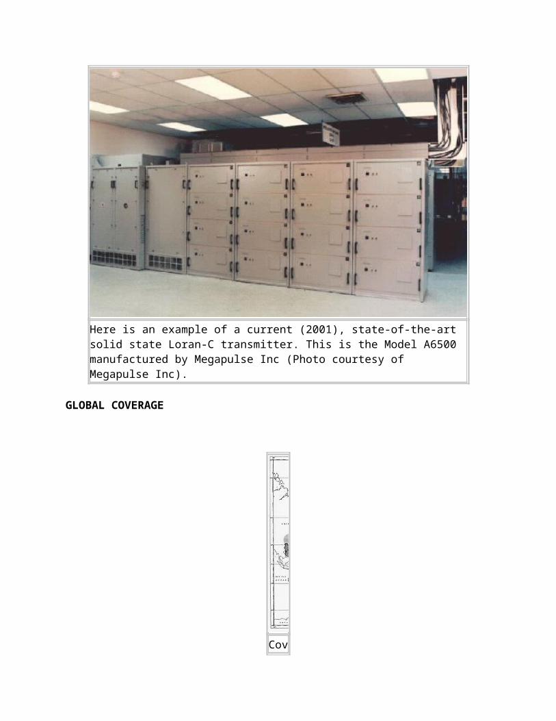
emergency battery power supply maintained synchronization during brief (up to 5 min) power outages. (Photo courtesy RCN)
CLOSURE
With the Global Positioning System (GPS) being declared fully operational, the use of OMEGA had dwindled to a point where continued operation was not economically justified. The 1994 edition of the United States Federal Radionavigation Plan (FRP), which delineates policies and plans for federally provided radionavigation services, stated "the U.S. expects to continue OMEGA operations until September 30, 1997, to accommodate the transition of civil aviation users to GPS. Continued operation after that date will depend upon validating requirements for OMEGA that cannot be met by GPS or another system." The Federal Aviation Administration (FAA) completed its review of Omega navigation requirements for the U.S. aviation industry and notified the U.S. Coast Guard that most users will complete their conversion to GPS technology by September 1997. OMEGA was shut down precisely at 0300Z on September 30, 1997 - the end of another era. To VLF experimenters, the very high power OMEGA signals were both a blessing and a curse; a blessing in that they provided convenient test signals in the 9.5 to 14 kHz range, and a curse in that they tended to interfere with the reception of natural radio phenomena such as "whistlers" and "dawn chorus".
Besides affecting users, the closure of Omega had a small impact on tourism. Because of their prominent antennas and interesting mission, many Omega stations were recognized in their local areas as major tourist attractions, including official listings and pictures in area tourist brochures. Omega station North Dakota was located in the town of LaMoure, with a population of less than 1,000. In this small town is located the Omega Motel, the Omega Plaza, and the Omega Room at one of the restaurants. After Omega ceased, the USN took over the site from the US Coast Guard and continued VLF communications under the name of Naval Computer and Telecommunications Area Master Station Atlantic (NCTAMSLANT). The mission statement of the new station is: " To manage, operate, and maintain those facilities, systems, equipment, and devices necessary to provide requisite communications and information system support for the command, operational control and administration of the naval establishment, and the fixed submarine broadcast system; to test and evaluate new Very Low Frequency (VLF) broadcast technology and minimize downtime of operational sites during VLF system upgrades and major transmitter and antenna maintenance". The people of LaMoure will not soon forget the Omega system as the 1200 foot tower still looms in the western horizon and a number of retired Coast Guardsmen now reside in LaMoure.
Omega Station Norway had a prominent sign along the road near the helix building proclaiming their antenna as the longest antenna span in Europe. The Japan tower was the highest structure in Japan, and the Argentina and Liberia towers were the tallest structures in their entire continents. Australia registered over 10,000 visitors per year to its station.
THE MESSAGE WHICH ANNOUNCED THE CLOSURE OF THE SYSTEM
The following message was sent by the United States Coast Guard to all OMEGA users advising of the system shutdown.
P 011416Z OCT 97 FM COGARD NAVCEN ALEXANDRIA VA//NIS// SUBJ: OMEGA STATUS AS OF 01 OCT 97 1. THE OMEGA NAVIGATION SYSTEM TERMINATED AND ALL STATIONS CEASED OMEGA TRANSMISSIONS AT 0300Z 30 SEPTEMBER 1997 IN ACCORDANCE WITH NAVCEN OPERATIONS ORDER DATED 141026Z AUG 97. 2. OFF AIR PERIODS 221000Z SEP 97 THROUGH 300300Z SEP 97: A. NONE B. NONE C. NONE D. NONE E. NONE F NONE G. NONE H. NONE 3. REDUCED POWER PERIODS 221000Z SEP 97 THROUGH 300300Z SEP 97: A. NONE B. DOWN 3.7 DB 221000Z TO 300300Z C. NONE D. NONE E. DOWN 1.7 DB 221000Z TO 230250Z DOWN 1.3 DB 230715Z TO 231215Z DOWN 4.2 DB 231415Z TO 232355Z DOWN 1.7 DB 241000Z TO 242225Z DOWN 1.4 DB 251440Z TO 251951Z DOWN 1.2 DB 260101Z TO 260230Z DOWN 5.0 DB 260740Z TO 270608Z DOWN 2.5 DB 271602Z TO 280335Z F. DOWN 1.9 DB 221700Z TO 230731Z DOWN 1.2 DB 241839Z TO 242023Z DOWN 2.4 DB 272100Z TO 280358Z G NONE H DOWN 1.6 DB 231230Z TO 231810Z DOWN 1.6 DB 250305Z TO 251800Z DOWN 1.6 DB 261750Z TO 262220Z 4. QUESTIONS REGARDING OMEGA STATUS/OPERATION MAY BE DIRECTED TO: PHONE NUMBER (703)313-5900.
A facsimile transmission received by the Navigation Center (NAVCEN) from the Japanese Maritime Safety Agency truly summarized the 25 year relationship between the U.S. and Japan. The FAX, received just days before the signal was terminated stated:
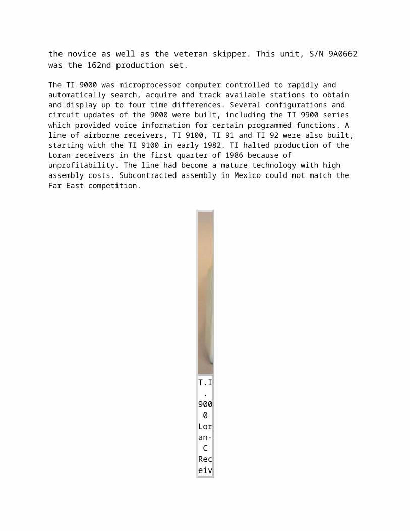
..."(The final status message) will shine brilliantly, foot marking the world wide radio navigation history cooperatively linking OMEGA with six partner nations. We can't say enough in praise of your excellent duties. In Japan, both the Station and the Analysis Office employees amount to nearly three hundred persons since opening time. They have a favorable impression of the system. Your friendship and kind support with us over the years has been deeply appreciated. It will stay with me as a rewarding memory of the valuable experience received from OMEGA. I hope that the OMEGA community members will continue to have a successful and enjoyable life."
These kind words were expressed by Toshiichiro Kawamura, Director of JMSA.
LORAC
LORAC-A (Long Range Accuracy, Version A)-LORAC-A is a local radio navigation system operated by the Eastern Space and Missile Center (ESMC). The LORAC-A system was originally installed in 1961 to support Pershing missile launches. The system is based on continuous wave (COO) phase comparison and has a reported accuracy of 15 meters within the STS 51-L search areas. Contact positions identified using LORAC-A navigation were relocated during classification and salvage phases of the salvage operation using GPS/LORAN-C systems, thereby validating the accuracy of the LORAN-A system. During STS 51 -L search and salvage operations the USAF range boat (LCU) utilized LORAC-A.
RAYDIST
RAYDIST (from a wedding of the words radio and distance) is a radio system for medium-range precision surveying in which the phases of two continuous-wave signals are compared. It is based on the heterodyne principle and uses low or medium frequencies.
The system was developed by the Hastings Instrument Company of Hampton Virginia which was founded in 1944 by Charles and Mary Hastings when Charles was only 30 years old. RAYDIST is first mentioned as a development in the April 18, 1947 edition of the Cass City Chronicle (Cass City, Michigan). RAYDIST first entered service in 1952 at the sea trials of the ocean liner SS United States. It was used to measure her speed for purposes or calculating fuel consumption.
RAYDIST counts lanes of hyperbolic phase difference on a Brush 2 channel medical recorder. Any number of receivers could be used at the same time in one "net". Nets operated between 1670 KHz to near 1800 KHz. In a single net, a center CW station transmitted around 1780 KHz, a Red station on 1780.210 KHz and a Green station on 1780.370 KHz. In each net, these offsets would be identical.
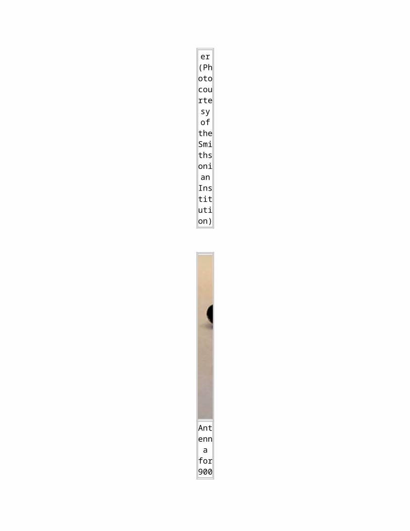
The user had to start from a known location. Then it was a matter of counting green and red lanes. The 210 Hz and 370 Hz audio tones drove resolvers which in turn ran gas meter heads. These could divide a lane into approximately 5,000 parts. Near shore accuracy could be in the one or two FOOT range!
The above describes type "N" (navigational) RAYDIST which permits multiple users in the same net with an accuracy about 50 to 100 ft at 50 miles offshore. There was a Distance Measuring (DM ) version of RAYDIST as well.
DM RAYDIST was used to calibrate the Inertial Navigation Systems on early nuclear submarines since there was no GPS in existence at the time. DM with a transmitter on the user vehicle could accommodate only one user at a time. DM used frequencies around 3 MHz and produced concentric lanes of phase difference. Since the gas meter readout heads could resolve about 5,000 divisions in a single lane, its accuracy was about 2 or 3 feet at 300 miles from shore!
Three other RAYDIST variants were mentioned on the web but no definitions provided. These are: type " E ", type "E.R" and type "T". If anyone can expand on these it would be greatly appreciated. Contact: [email protected].
Among its applications, it was to locate oil wells in the Gulf of Mexico. Shell Oil was a good customer of RAYDIST and it was also part of the Petroleum Helicopters operation in the mid 1960s. RAYDIST "nets" ran from Texas to the west coast of Florida.
The system was never used in Europe but various web documents indicates indicate useage in Tasmania, the Fly River in New Guinea, Brazil and Portuguese Guinea. The system was evidently a forerunner of AERODIST which was an aircraft based system made by a South African company. RAYDIST eventually succumbed to history's scrap heap once satellite GPS became popular.
I N E R T I A L N A V I G A T I O N S Y S T E M
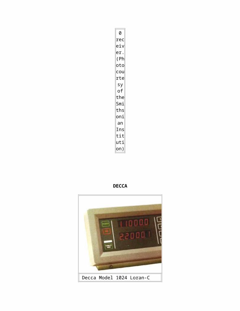
Introduction
A technology known as INS, or Inertial Navigation System originally developed in the mid 60s for Missile Guidance systems has undergone an extensive evolutionary process and has now been introduced into Civil Aviation. Aircraft such as the Boeing 747 are now fitted with INS systems. INS is usually coupled with GPS (Global Positioning Systems) to be used to navigate by global Latitude and Longitudinal co-ordinates and also allows for real-time calibration of the INS.
Inertial navigation is based on techniques, which have been invented and developed after the Second World War. The first systems were built of mechanical gyros, which required very complicated technical and power consuming constructions being prone to failure. Later on 'solid state' solutions have been realized by using only discrete integrated electro-mechanical or electro-optical sensors. These 'solid state' systems had no moving parts (therefore Strapdown Inertial Navigation System), but consisted of expensive laser-gyros and integrated sensor devices in MEMS technology (Micro Electro-Mechanical System). Inertial navigation systems (INS) are used in civil and military aviation, cruise missiles, submarines and space technology.
Basic Principles of the INS
Every object that is free to move in space has six "degrees of freedom" - or ways it can move. There are three linear degrees of freedom (x, y, z) that specify the position and three rotational degrees of freedom (theta (pitch), psi (yaw), and phi (roll)) that specify the attitude. An Inertial Navigation System is a device that is used to determine one's position relative to a known start point. The basic INS consists of gyroscopes, accelerometers, a navigation computer, and a clock. Gyroscopes are instruments that sense angular rate. They are used to give the orientation of an object (for example: angles of roll, pitch, and yaw of an airplane). Accelerometers sense a linear change in rate (acceleration) along a given axis.
The INS was originally created to permit navigation on vessels that were unable to use the more traditional means of navigation, such as celestial navigation, dead reckoning or landmarks. These were generally of three types: ships that travelled in areas of extreme cloud cover, submarines, and long-range aircraft. None of these can reliably and easily perform star sightings to fix position, and may undergo numerous course and speed changes between external reference 'fixes.'
It was used to build a navigating autopilot for aircraft, as well; rather than a simple device that kept the attitude of the plane constant, autopilots could now actually direct the airplane from place to place, lowering the workload on the pilots, who were coping with the swiftly increasing complexity of modern aircraft.
It is used to navigate under ice, in fog, in deep tree cover, and more. Modern technology has increased the reliability of the INS unit by reducing the number of moving parts - in some cases, to zero. Ring laser
gyros, despite problems with phase lock, can be manufactured using solid-state microelectronics techniques, allowing entire INS units to be placed into devices the size of a box of matches - or smaller, depending on your classification level, I suppose. Such systems are of extreme use in guiding unmanned weaponry of all sorts.
The overriding advantage of inertial navigation is that it requires no communication with the outside world. If a vessel is unable to contact the outside, or is disinclined to trust the answers it receives, there is another option for finding one's way. They aren't perfect, naturally. INS units suffer from 'drift', or a continually increasing position error. This is due to the fact that measurement inside the unit is imperfect, and with every change in acceleration, additional error is introduced into the navigation calculation; after the calculation is done, this error is described as a distance. It is a radius from the indicated position which defines a circle the actual position is likely within; as such, it is usually accompanied by a probability rating, e.g. after 24 hours of operation, an INS may report a position to within 200 meters, with a confidence of 0.95.
Although ships and aircraft continue to carry INS units and the technology keeps improving, the most important advances have come in the form of external checks and references for the INS system. The most pervasive of these is the Global Positioning System, which is a natural partner; although constantly available and fairly precise, GPS suffers from the fact that its weak radio signals cannot usually be received when under cover of any structure. Sometimes even trees or car windshields can interrupt service, with a cheap receiver. So, many high-end navigation units use a combination INS/GPS system, in which the system uses GPS to determine its location, until it loses the signal. At that point, the INS takes over from the last known good position, and offers information on movement since the loss of signal.
In a typical inertial navigation system, there are three mutually orthogonal gyros and three mutually orthogonal accelerometers. This accelerometer configuration will give three orthogonal acceleration components which can be vectorially summed. Combining the gyro-sensed orientation information with the summed accelerometer outputs yields the INU's total acceleration in 3D space. At each time-step of the system's clock, the navigation computer time integrates this quantity once to get the body's velocity vector. The velocity vector is then time integrated, yielding the position vector. These steps are continuously iterated throughout the navigation process.
Two Types of INS
1. Gimballed INS
At the dawn of inertial navigation, all gyroscopes were based on a rotating platform connected to an outer housing by low friction gimbals. In a gimbaled system (Figure 1.1), a set of mutually orthogonal accelerometers are attached to the gimbaled gyro platform and hence are held in a fixed inertial orientation. In the event of an angular motion, the rotating platforms tend to maintain their original orientation per Newton's First Law. Pickoffs on the gimbals measure the movement of the outer body around the steady platform and the accelerometers measure the body's acceleration in the fixed inertial axes.
Simplified Schematic Diagram of a Gimballed INS Mechanism.
One of the limitations of a gimbaled system is its tendency to ``lock up'' in certain maneuvers. An example of gimbal lock is shown Figure 1.2. This example case has an airplane initially flying straight and level, then altering its pitch to a full vertical climb, and then going through a pure azimuthal turn through 90 degrees. The corresponding gimbal movements about the gyro platform results in a locked position yielding errors.
Photo of Internals of a Gimballed Inertial Platform INS Mechanism.
2. Strapdown INS
The 70s introduced Strapdown INS, which was similar in principal to theEarly IN systems but had no moving parts, infact the gyros and accelerometers were fixed i.e strapped down, to the chassis/cicuitry of the equipment. The strapdown systems suffered from a major flaw in that power consumption was so high, thermal problems were introduced, making it unreliable.
and hence using electronic circuitry can calculate the position relative to the start, thus they cannot determine their initial location, just the change relative to it. The early IN systems relied heavily on a precision engineered mechanism.
Ring Laser Gyro INS
RLG INS (Ring Laser Gyro INS), is another form of Strapdown INS (i.e has no reliance on a physical mechanism as such). RLG uses a solid state glass block with three drilled tubes, mirrors placed at each coner act as optical resonators and reflect the beam.
The tubes are filled with a Helium/Neon Halogen mixture and a High voltage (about 1Kv) is applied, just like a Tube-light or Cathode Ray tube in a Telivision set. RLG systems use two counter beams around the tube initially at the same frequency, as the unit is moved the distance each photon (sub atomic particle responsible for light) has to travel (to the next mirror) changes,
resulting in a subtle change in Frequency of that beam. The frequency of the beam can be measured then the change in angle be calculated from Delta.
Simplified Schematic Diagram of a RLG INS System
Internals of the RLG System Housing and Circuitry of the RLG INS unit
In the recent 10 years or so, precision engineering of mechanical parts hasimproved dramatically making it possible to create accurate gimbaledIN systems, which are currently being used in Civil Aviation Applications.
Advantages and Disadvantages of Gimbaled vs. Strapdown
In comparing gimbaled versus Strapdown INS’s, each displays it's own advantages and disadvantages. Perhaps a gimbaled INS's primary advantage is it's inherently lower error. Since it's three orthogonal accelerometers are held in a fixed inertial orientation, only the vertically oriented one will be measuring gravity (and therefore experiencing gravity-related errors). This is in contrast to the strapdown system, whose accelerometers all move and rotate about, each experiencing the acceleration of gravity (and the subsequent errors). Another gimbaled system advantage is the simplicity of its gyros: gimbaled system gyros' primary function is to spin, to maintain a high moment of inertia, whereas strapdown gyros need to actually measure the subtended angles of motion.
The strapdown inertial navigation system's main advantage over the gimbaled system is the simplicity of its mechanical design. Where a gimbaled system requires elaborate and intricate mechanical structures for its gimbals, pickoffs, and low-friction platform connections, the strapdown system is entirely fixed to the body in motion.
I N E R T I A L N A V I G A T I O N S Y S T E M
Introduction
A technology known as INS, or Inertial Navigation System originally developed in the mid 60s for Missile Guidance systems has undergone an extensive evolutionary process and has now been introduced into Civil Aviation. Aircraft such as the Boeing 747 are now fitted with INS systems. INS is usually coupled with GPS (Global Positioning Systems) to be used to navigate by global Latitude and Longitudinal co-ordinates and also allows for real-time calibration of the INS.
Inertial navigation is based on techniques, which have been invented and developed after the Second World War. The first systems were built of mechanical gyros, which required very complicated technical and power consuming constructions being prone to failure. Later on 'solid state' solutions have been realized by using only discrete integrated electro-mechanical or electro-optical sensors. These 'solid state' systems had no moving parts (therefore Strapdown Inertial Navigation System), but consisted of expensive laser-gyros and integrated sensor devices in MEMS technology (Micro Electro-Mechanical System). Inertial navigation systems (INS) are used in civil and military aviation, cruise missiles, submarines and space technology.
Basic Principles of the INS
Every object that is free to move in space has six "degrees of freedom" - or ways it can move. There are three linear degrees of freedom (x, y, z) that specify the position and three rotational degrees of freedom (theta (pitch), psi (yaw), and phi (roll)) that specify the attitude. An Inertial Navigation System is a device that is used to determine one's position relative to a known start point. The basic INS consists of gyroscopes, accelerometers, a navigation computer, and a clock. Gyroscopes are instruments that sense angular rate. They are used to give the orientation of an object (for example: angles of roll, pitch, and yaw of an airplane). Accelerometers sense a linear change in rate (acceleration) along a given axis.
The INS was originally created to permit navigation on vessels that were unable to use the more traditional means of navigation, such as celestial navigation, dead reckoning or landmarks. These were generally of three types: ships that travelled in areas of extreme cloud cover, submarines, and long-range aircraft. None of these can reliably and easily perform star sightings to fix position, and may undergo numerous course and speed changes between external reference 'fixes.'
It was used to build a navigating autopilot for aircraft, as well; rather than a simple device that kept the attitude of the plane constant, autopilots could now actually direct the airplane from place to place,

lowering the workload on the pilots, who were coping with the swiftly increasing complexity of modern aircraft.
It is used to navigate under ice, in fog, in deep tree cover, and more. Modern technology has increased the reliability of the INS unit by reducing the number of moving parts - in some cases, to zero. Ring laser gyros, despite problems with phase lock, can be manufactured using solid-state microelectronics techniques, allowing entire INS units to be placed into devices the size of a box of matches - or smaller, depending on your classification level, I suppose. Such systems are of extreme use in guiding unmanned weaponry of all sorts.
The overriding advantage of inertial navigation is that it requires no communication with the outside world. If a vessel is unable to contact the outside, or is disinclined to trust the answers it receives, there is another option for finding one's way. They aren't perfect, naturally. INS units suffer from 'drift', or a continually increasing position error. This is due to the fact that measurement inside the unit is imperfect, and with every change in acceleration, additional error is introduced into the navigation calculation; after the calculation is done, this error is described as a distance. It is a radius from the indicated position which defines a circle the actual position is likely within; as such, it is usually accompanied by a probability rating, e.g. after 24 hours of operation, an INS may report a position to within 200 meters, with a confidence of 0.95.
Although ships and aircraft continue to carry INS units and the technology keeps improving, the most important advances have come in the form of external checks and references for the INS system. The most pervasive of these is the Global Positioning System, which is a natural partner; although constantly available and fairly precise, GPS suffers from the fact that its weak radio signals cannot usually be received when under cover of any structure. Sometimes even trees or car windshields can interrupt service, with a cheap receiver. So, many high-end navigation units use a combination INS/GPS system, in which the system uses GPS to determine its location, until it loses the signal. At that point, the INS takes over from the last known good position, and offers information on movement since the loss of signal.
In a typical inertial navigation system, there are three mutually orthogonal gyros and three mutually orthogonal accelerometers. This accelerometer configuration will give three orthogonal acceleration components which can be vectorially summed. Combining the gyro-sensed orientation information with the summed accelerometer outputs yields the INU's total acceleration in 3D space. At each time-step of the system's clock, the navigation computer time integrates this quantity once to get the body's velocity vector. The velocity vector is then time integrated, yielding the position vector. These steps are continuously iterated throughout the navigation process.
Two Types of INS
1. Gimballed INS
At the dawn of inertial navigation, all gyroscopes were based on a rotating platform connected to an outer housing by low friction gimbals. In a gimbaled system (Figure 1.1), a set of mutually orthogonal accelerometers are attached to the gimbaled gyro platform and hence are held in a fixed inertial orientation. In the event of an angular motion, the rotating platforms tend to maintain their original orientation per Newton's First Law. Pickoffs on the gimbals measure the movement of the outer body around the steady platform and the accelerometers measure the body's acceleration in the fixed inertial axes.
Simplified Schematic Diagram of a Gimballed INS Mechanism.
One of the limitations of a gimbaled system is its tendency to ``lock up'' in certain maneuvers. An example of gimbal lock is shown Figure 1.2. This example case has an airplane initially flying straight and level, then altering its pitch to a full vertical climb, and then going through a pure azimuthal turn through 90 degrees. The corresponding gimbal movements about the gyro platform results in a locked position yielding errors.
Photo of Internals of a Gimballed Inertial Platform INS Mechanism.
2. Strapdown INS
The 70s introduced Strapdown INS, which was similar in principal to theEarly IN systems but had no moving parts, infact the gyros and accelerometers were fixed i.e strapped down, to the chassis/cicuitry of the equipment. The strapdown systems suffered from a major flaw in that power consumption was so high, thermal problems were introduced, making it unreliable.
and hence using electronic circuitry can calculate the position relative to the start, thus they cannot determine their initial location, just the change relative to it. The early IN systems relied heavily on a precision engineered mechanism.
Ring Laser Gyro INS
RLG INS (Ring Laser Gyro INS), is another form of Strapdown INS (i.e has no reliance on a physical mechanism as such). RLG uses a solid state glass block with three drilled tubes, mirrors placed at each coner act as optical resonators and reflect the beam.
The tubes are filled with a Helium/Neon Halogen mixture and a High voltage (about 1Kv) is applied, just like a Tube-light or Cathode Ray tube in a Telivision set. RLG systems use two counter beams around the tube initially at the same frequency, as the unit is moved the distance each photon (sub atomic particle responsible for light) has to travel (to the next mirror) changes,
resulting in a subtle change in Frequency of that beam. The frequency of the beam can be measured then the change in angle be calculated from Delta.
Simplified Schematic Diagram of a RLG INS System
Internals of the RLG System Housing and Circuitry of the RLG INS unit
In the recent 10 years or so, precision engineering of mechanical parts hasimproved dramatically making it possible to create accurate gimbaledIN systems, which are currently being used in Civil Aviation Applications.
Advantages and Disadvantages of Gimbaled vs. Strapdown
In comparing gimbaled versus Strapdown INS’s, each displays it's own advantages and disadvantages. Perhaps a gimbaled INS's primary advantage is it's inherently lower error. Since it's three orthogonal accelerometers are held in a fixed inertial orientation, only the vertically oriented one will be measuring gravity (and therefore experiencing gravity-related errors). This is in contrast to the strapdown system, whose accelerometers all move and rotate about, each experiencing the acceleration of gravity (and the subsequent errors). Another gimbaled system advantage is the simplicity of its gyros: gimbaled system gyros' primary function is to spin, to maintain a high moment of inertia, whereas strapdown gyros need to actually measure the subtended angles of motion.
The strapdown inertial navigation system's main advantage over the gimbaled system is the simplicity of its mechanical design. Where a gimbaled system requires elaborate and intricate mechanical structures for its gimbals, pickoffs, and low-friction platform connections, the strapdown system is entirely fixed to the body in motion.