national science bowl teacher workshop 2013
TRANSCRIPT

National Science Bowl Teacher Workshop 2013
2
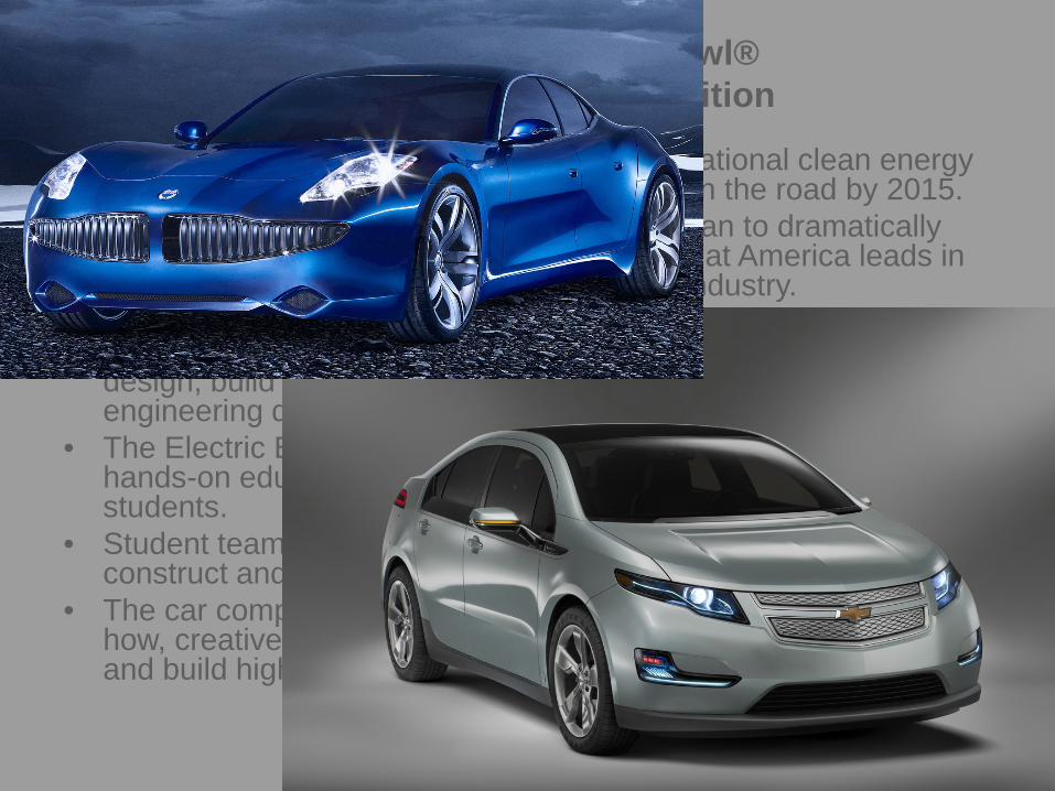
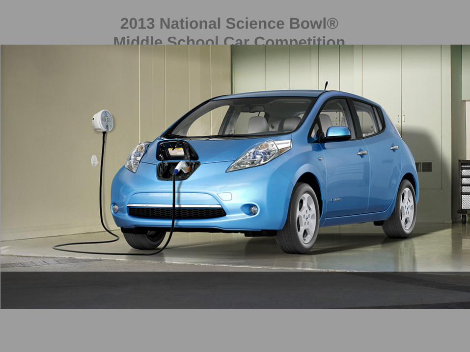
Introduction • One of the Department of Energy’s (DOE) national clean energy goals is to put one
million electric vehicles on the road by 2015.
• This is a key milestone in DOE’s strategic plan to dramatically reduce our dependence on oil and ensure that America leads in the growing electric vehicle manufacturing industry.
• As part of DOE’s education outreach, middle school students competing at the National Science Bowl® event in 2013 will design, build and race model lithium ion battery cars as part of an engineering design competition.
• The Electric Battery Car Competition is a classroom-based, hands-on educational program for 6th, 7th, and 8th grade students.
• Student teams apply math, engineering, science, and creativity to construct and race a model electric-powered car.
• The car competition challenges students to use scientific know-how, creative thinking, experimentation, and teamwork to design and build high-performance model electric vehicles.
2013 National Science Bowl® Middle School Car Competition
3
Introduction • One of the Department of Energy’s (DOE) national clean energy
goals is to put one million electric vehicles on the road by 2015. • This is a key milestone in DOE’s strategic plan to dramatically
reduce our dependence on oil and ensure that America leads in the growing electric vehicle manufacturing industry.
• As part of DOE’s education outreach, middle school students competing at the National Science Bowl® event in 2013 will design, build and race model lithium ion battery cars as part of an engineering design competition.
• The Electric Battery Car Competition is a classroom-based, hands-on educational program for 6th, 7th, and 8th grade students.
• Student teams apply math, engineering, science, and creativity to construct and race a model electric-powered car.
• The car competition challenges students to use scientific know-how, creative thinking, experimentation, and teamwork to design and build high-performance model electric vehicles.
2013 National Science Bowl® Middle School Car Competition

4
Introduction • One of the Department of Energy’s (DOE) national clean energy
goals is to put one million electric vehicles on the road by 2015. • This is a key milestone in DOE’s strategic plan to dramatically
reduce our dependence on oil and ensure that America leads in the growing electric vehicle manufacturing industry.
• As part of DOE’s education outreach, middle school students competing at the National Science Bowl® event in 2013 will design, build and race model lithium ion battery cars as part of an engineering design competition.
• The Electric Battery Car Competition is a classroom-based, hands-on educational program for 6th, 7th, and 8th grade students.
• Student teams apply math, engineering, science, and creativity to construct and race a model electric-powered car.
• The car competition challenges students to use scientific know-how, creative thinking, experimentation, and teamwork to design and build high-performance model electric vehicles.
2013 National Science Bowl® Middle School Car Competition

5
Introduction • One of the Department of Energy’s (DOE) national clean energy
goals is to put one million electric vehicles on the road by 2015. • This is a key milestone in DOE’s strategic plan to dramatically
reduce our dependence on oil and ensure that America leads in the growing electric vehicle manufacturing industry.
• As part of DOE’s education outreach, middle school students competing at the National Science Bowl® event in 2013 will design, build and race model lithium ion battery cars as part of an engineering design competition.
• The Electric Battery Car Competition is a classroom-based, hands-on educational program for 6th, 7th, and 8th grade students.
• Student teams apply math, engineering, science, and creativity to construct and race a model electric-powered car.
• The car competition challenges students to use scientific know-how, creative thinking, experimentation, and teamwork to design and build high-performance model electric vehicles.
2013 National Science Bowl® Middle School Car Competition
6
Introduction • One of the Department of Energy’s (DOE) national clean energy
goals is to put one million electric vehicles on the road by 2015. • This is a key milestone in DOE’s strategic plan to dramatically
reduce our dependence on oil and ensure that America leads in the growing electric vehicle manufacturing industry.
• As part of DOE’s education outreach, middle school students competing at the National Science Bowl® event in 2013 will design, build and race model lithium ion battery cars as part of an engineering design competition.
• The Electric Battery Car Competition is a classroom-based, hands-on educational program for 6th, 7th, and 8th grade students.
• Student teams apply math, engineering, science, and creativity to construct and race a model electric-powered car.
• The car competition challenges students to use scientific know-how, creative thinking, experimentation, and teamwork to design and build high-performance model electric vehicles.
2013 National Science Bowl® Middle School Car Competition
7
Goals and Description The primary goals of the programs are to: • Generate enthusiasm for science and engineering at a crucial stage in the
educational development of young people, • Improve students' understanding of scientific concepts and renewable energy
technologies, and • Encourage young people to consider and prepare for technical careers at an early
age.
Program description: • Students use mathematics and science principles together with their creativity in a
fun, hands-on educational program. • Using engineering principles, students get excited about generating ideas in a group
and then building and modifying models based on these ideas. • Students can see for themselves how changes in design are reflected in car
performance. • Students work together on teams to apply problem solving and project management
skills. • Students document their questions, discoveries, and progress in a Design Document
which will be submitted for review.

Please read through all directions before beginning construction!
9
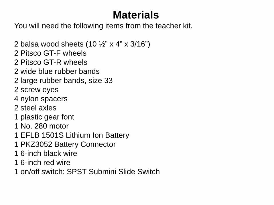
Materials You will need the following items from the teacher kit. 2 balsa wood sheets (10 ½” x 4” x 3/16”) 2 Pitsco GT-F wheels 2 Pitsco GT-R wheels 2 wide blue rubber bands 2 large rubber bands, size 33 2 screw eyes 4 nylon spacers 2 steel axles 1 plastic gear font 1 No. 280 motor 1 EFLB 1501S Lithium Ion Battery 1 PKZ3052 Battery Connector 1 6-inch black wire 1 6-inch red wire 1 on/off switch: SPST Submini Slide Switch

10
Tools Required 1. Soldering iron 2. Hobby knife or coping saw 3. Glue gun 4. Needle-nose pliers 5. 2 C-clamps 6. Ruler
11
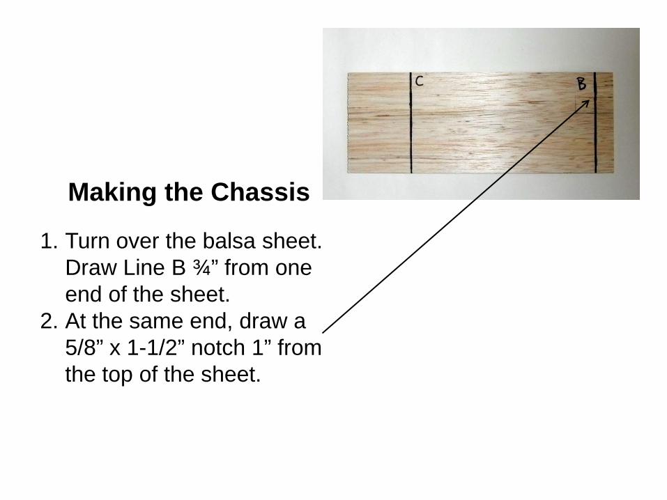
Making the Chassis 1. Turn over the balsa sheet.
Draw Line B ¾” from one end of the sheet.
2. At the same end, draw a 5/8” x 1-1/2” notch 1” from the top of the sheet.
12
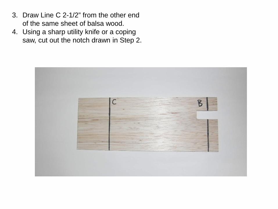
3. Draw Line C 2-1/2” from the other end of the same sheet of balsa wood.
4. Using a sharp utility knife or a coping saw, cut out the notch drawn in Step 2.

13
5. Turn over the balsa wood and draw a line one inch from the opposite side of the notch. Label this line D.
6. Using either your salt container as a guide or with a ruler make a mark approximately 5-7/8” from line D. Label this line E.
14
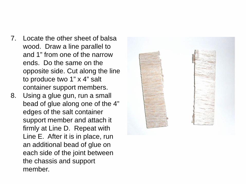
7. Locate the other sheet of balsa wood. Draw a line parallel to and 1” from one of the narrow ends. Do the same on the opposite side. Cut along the line to produce two 1” x 4” salt container support members.
8. Using a glue gun, run a small bead of glue along one of the 4” edges of the salt container support member and attach it firmly at Line D. Repeat with Line E. After it is in place, run an additional bead of glue on each side of the joint between the chassis and support member.

15
Wheels, Gears, and Axles
Rear Axle Assembly 1. Locate the plastic gear
font. Detach Gear I from the font.
2. Inspect the gear and using a sharp knife, carefully remove any plastic flashing between the gear teeth.
3. Place the gear on a table. Insert one of the steel axles into the gear.
Plastic Gear Font
16
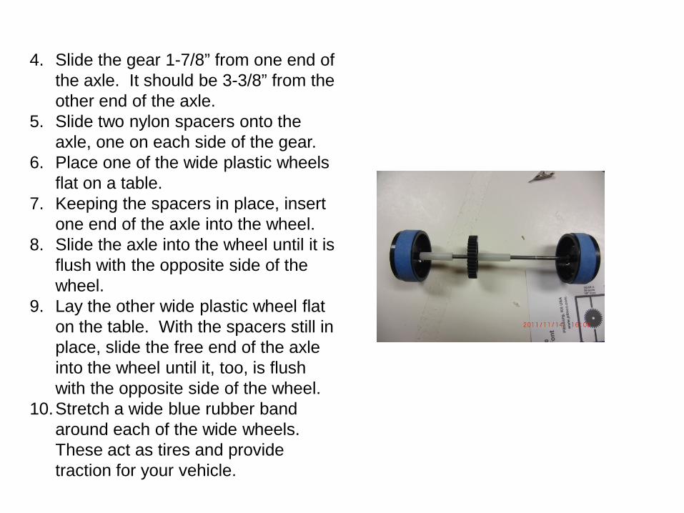
4. Slide the gear 1-7/8” from one end of the axle. It should be 3-3/8” from the other end of the axle.
5. Slide two nylon spacers onto the axle, one on each side of the gear.
6. Place one of the wide plastic wheels flat on a table.
7. Keeping the spacers in place, insert one end of the axle into the wheel.
8. Slide the axle into the wheel until it is flush with the opposite side of the wheel.
9. Lay the other wide plastic wheel flat on the table. With the spacers still in place, slide the free end of the axle into the wheel until it, too, is flush with the opposite side of the wheel.
10.Stretch a wide blue rubber band around each of the wide wheels. These act as tires and provide traction for your vehicle.
17
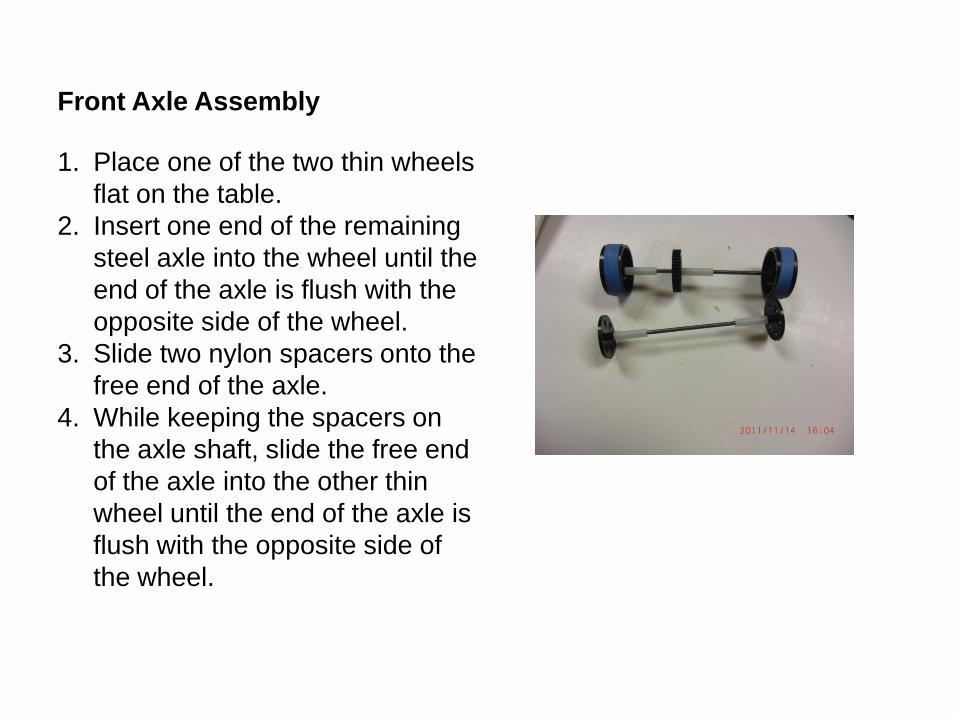
Front Axle Assembly 1. Place one of the two thin wheels
flat on the table. 2. Insert one end of the remaining
steel axle into the wheel until the end of the axle is flush with the opposite side of the wheel.
3. Slide two nylon spacers onto the free end of the axle.
4. While keeping the spacers on the axle shaft, slide the free end of the axle into the other thin wheel until the end of the axle is flush with the opposite side of the wheel.
18
Attaching Axle Assemblies to Chassis
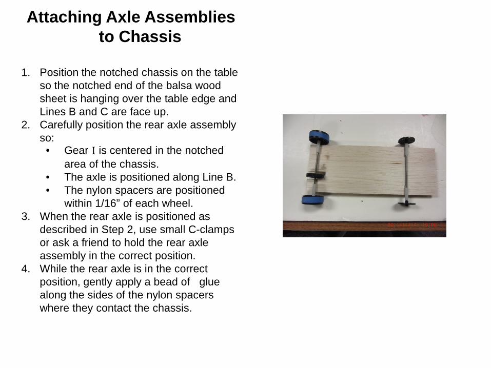
1. Position the notched chassis on the table
so the notched end of the balsa wood sheet is hanging over the table edge and Lines B and C are face up.
2. Carefully position the rear axle assembly so:
• Gear I is centered in the notched area of the chassis.
• The axle is positioned along Line B. • The nylon spacers are positioned
within 1/16” of each wheel. 3. When the rear axle is positioned as
described in Step 2, use small C-clamps or ask a friend to hold the rear axle assembly in the correct position.
4. While the rear axle is in the correct position, gently apply a bead of glue along the sides of the nylon spacers where they contact the chassis.
19
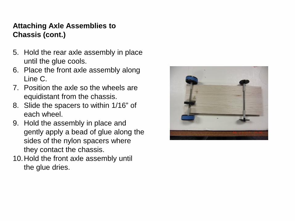
Attaching Axle Assemblies to Chassis (cont.) 5. Hold the rear axle assembly in place
until the glue cools. 6. Place the front axle assembly along
Line C. 7. Position the axle so the wheels are
equidistant from the chassis. 8. Slide the spacers to within 1/16” of
each wheel. 9. Hold the assembly in place and
gently apply a bead of glue along the sides of the nylon spacers where they contact the chassis.
10.Hold the front axle assembly until the glue dries.
20
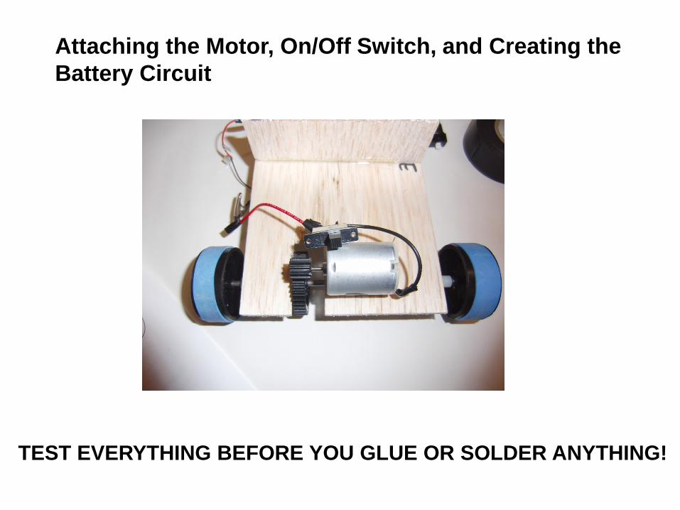
TEST EVERYTHING BEFORE YOU GLUE OR SOLDER ANYTHING!
Attaching the Motor, On/Off Switch, and Creating the Battery Circuit
21
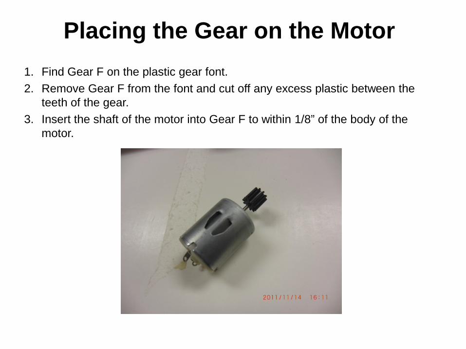
Placing the Gear on the Motor 1. Find Gear F on the plastic gear font. 2. Remove Gear F from the font and cut off any excess plastic between the
teeth of the gear. 3. Insert the shaft of the motor into Gear F to within 1/8” of the body of the
motor.
22
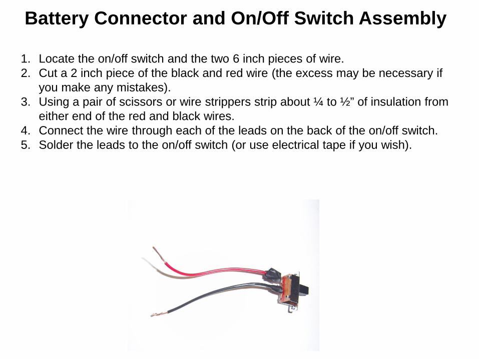
Battery Connector and On/Off Switch Assembly
1. Locate the on/off switch and the two 6 inch pieces of wire. 2. Cut a 2 inch piece of the black and red wire (the excess may be necessary if
you make any mistakes). 3. Using a pair of scissors or wire strippers strip about ¼ to ½” of insulation from
either end of the red and black wires. 4. Connect the wire through each of the leads on the back of the on/off switch. 5. Solder the leads to the on/off switch (or use electrical tape if you wish).

23
6. Find the battery connector. (DO NOT PLUG IN YOUR BATTERY AT THIS POINT!) 7. Connect the black wire from the battery connector to one of the metal leads on the motor. 8. Connect the red wire from the battery connector to the red wire coming from the on/off
switch. 9. Connect the black wire from the on/off switch to the other metal lead on the motor. 10. Attach your battery to the battery connector. This may cause the motor may turn on. 11. Turn the switch on to verify that the car will run forward. The gear on the motor will spin
the opposite direction you want the wheels to go. If the wheels move forward you can solder all leads. If not, switch the wires highlighted below in the diagram and retest.
Twist wires together at the highlighted areas and use electrical tape to secure. DO NOT SOLDER HERE! The wires may need to be switched if your car runs backwards.

24
Motor
On/Off Switch
Battery Connector
Do not solder until testing is complete.
The assembly of the motor, on/off switch and battery connector is shown below before being placed onto the chassis. The alligator clips are placed where the wires may need to be switched if the car runs backwards.
25
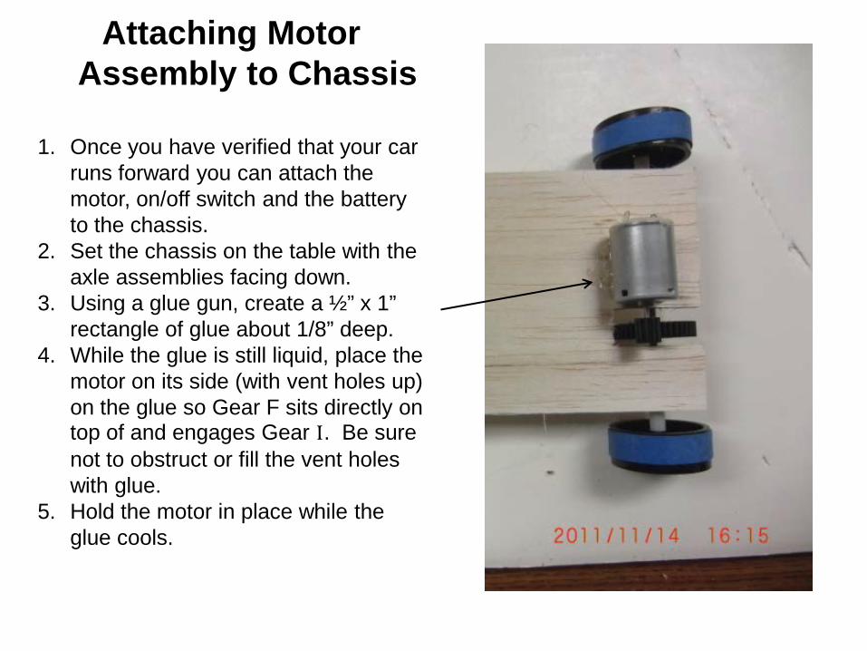
Attaching Motor Assembly to Chassis
1. Once you have verified that your car
runs forward you can attach the motor, on/off switch and the battery to the chassis.
2. Set the chassis on the table with the axle assemblies facing down.
3. Using a glue gun, create a ½” x 1” rectangle of glue about 1/8” deep.
4. While the glue is still liquid, place the motor on its side (with vent holes up) on the glue so Gear F sits directly on top of and engages Gear I. Be sure not to obstruct or fill the vent holes with glue.
5. Hold the motor in place while the glue cools.
26
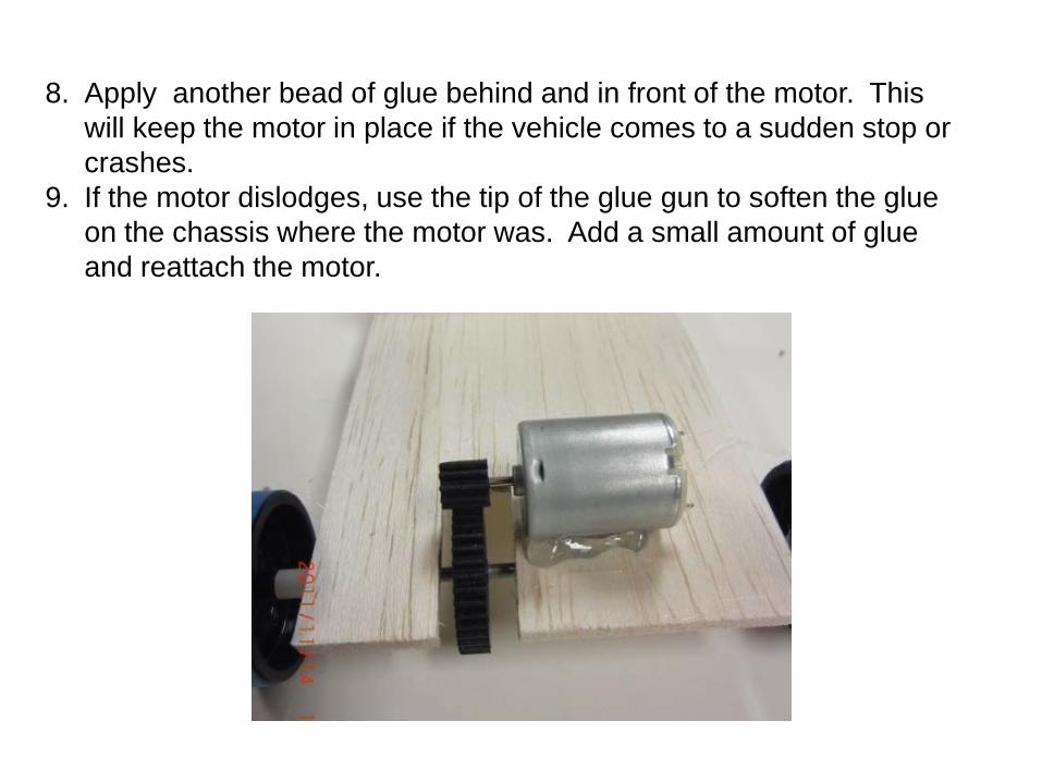
8. Apply another bead of glue behind and in front of the motor. This will keep the motor in place if the vehicle comes to a sudden stop or crashes.
9. If the motor dislodges, use the tip of the glue gun to soften the glue on the chassis where the motor was. Add a small amount of glue and reattach the motor.
27
TEST EVERYTHING BEFORE YOU GLUE OR SOLDER ANYTHING!
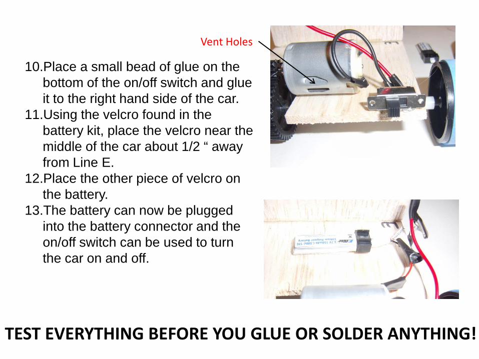
10.Place a small bead of glue on the bottom of the on/off switch and glue it to the right hand side of the car.
11.Using the velcro found in the battery kit, place the velcro near the middle of the car about 1/2 “ away from Line E.
12.Place the other piece of velcro on the battery.
13.The battery can now be plugged into the battery connector and the on/off switch can be used to turn the car on and off.
Vent Holes
28
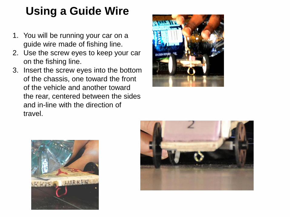
Using a Guide Wire
1. You will be running your car on a guide wire made of fishing line.
2. Use the screw eyes to keep your car on the fishing line.
3. Insert the screw eyes into the bottom of the chassis, one toward the front of the vehicle and another toward the rear, centered between the sides and in-line with the direction of travel.

29
Attaching the Salt Container 1. Place the salt container between the two wood supports and using strings,
rubber bands, or any other sort of device attach the salt container to the car. The salt container must be removable and cannot fall off during the race (this will result in a DNF).


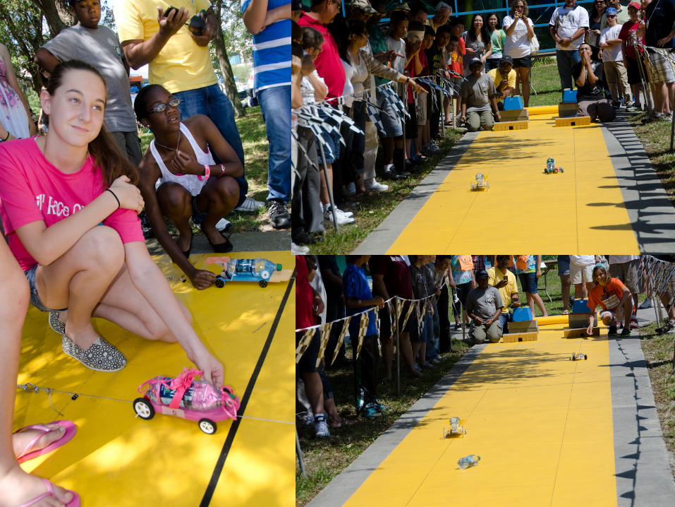
Middle School Car Competition
RULES

Design Document Rubric

33
Category 2 1 0 Score Comments Cover Page
One point only X Included with Name of school and team members.
No cover page included
Advantages and disadvantages of electric vehicles essay
Essay describes multiple advantages and disadvantages of EV.
Does not describe either multiple advantages or multiple disadvantages.
No essay
Component List All components and quantities listed.
Does not include all components and quantities.
No component list.
Final Specifications of Vehicle
Includes:
1 Body measurements (Length and Width)
2 Mass
3 Gear ratio
4Drive type
5Top average speed
Some specifications included
No final specs included.
Scaled Drawings Includes both top and side views.
Drawings are to scale.
Scale included.
Does not include both top and side views.
Drawings are not to scale.
Scale not included
No scaled drawings included.
Assembly Procedures With Photos
Includes detailed assembly procedures
Includes photos of vehicle being built or as finished.
Assembly procedures are not detailed or photos are not included.
No assembly procedures or photos.
Issues ,Problems and Solutions
At least three issues or problems encountered and solutions are described.
Less than three problems or issues and the solutions are described.
No description of problems, issues or solutions described
What Did You Learn Essay.
Essay describes lessons learned in detail.
Essay lacks detail. No essay included.
Design Document Rubric

BATTERY SAFETY
35
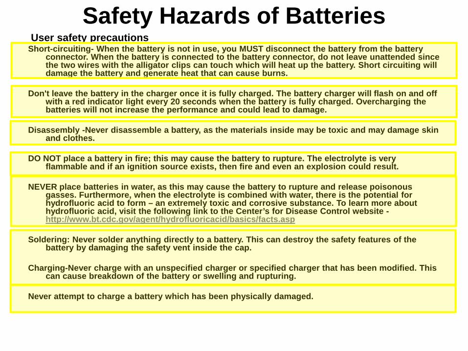
User safety precautions Short-circuiting- When the battery is not in use, you MUST disconnect the battery from the battery
connector. When the battery is connected to the battery connector, do not leave unattended since the two wires with the alligator clips can touch which will heat up the battery. Short circuiting will damage the battery and generate heat that can cause burns.
Don't leave the battery in the charger once it is fully charged. The battery charger will flash on and off
with a red indicator light every 20 seconds when the battery is fully charged. Overcharging the batteries will not increase the performance and could lead to damage.
Disassembly -Never disassemble a battery, as the materials inside may be toxic and may damage skin
and clothes. DO NOT place a battery in fire; this may cause the battery to rupture. The electrolyte is very
flammable and if an ignition source exists, then fire and even an explosion could result. NEVER place batteries in water, as this may cause the battery to rupture and release poisonous
gasses. Furthermore, when the electrolyte is combined with water, there is the potential for hydrofluoric acid to form – an extremely toxic and corrosive substance. To learn more about hydrofluoric acid, visit the following link to the Center’s for Disease Control website - http://www.bt.cdc.gov/agent/hydrofluoricacid/basics/facts.asp
Soldering: Never solder anything directly to a battery. This can destroy the safety features of the
battery by damaging the safety vent inside the cap. Charging-Never charge with an unspecified charger or specified charger that has been modified. This
can cause breakdown of the battery or swelling and rupturing. Never attempt to charge a battery which has been physically damaged.
Safety Hazards of Batteries

36
Safety Hazards of Batteries (continued)
User safety precautions Avoid designing airtight battery compartments. In some cases, gases (oxygen, hydrogen) may be
given off, and there is a danger of a battery bursting or rupturing if ignited by sparks. Do not use a battery in an appliance or purpose for which it was not intended. Safety Procedures If the foil packaging on the battery does break, vent the room and leave area. If a fire starts, call the fire department immediately. The only extinguisher that will work on a Lithium-
ion Battery fire is a Class D Fire Extinguisher or Dry Sand or Dry Table Salt.
-0.05
0
0.05
0.1
0.15
0.2
0.25
0.3
0.35
-20
0
20
40
60
80
100
120
0 20 40 60 80 100 120
Volta
ge (V
)
Tem
pera
ture
(C) /
Cur
rent
(A)
Time (sec)
Discharge Current Cell Temp Ambient Temp Cell Voltage

2012 BAT Mobile Cars

38 Double Elimination: Third Place
Solid Mount & Gear
Contact
Flexible Wheels
No Switch
Strong Frame
Simple, Strong Bottle Insert
Weak Wire Guide
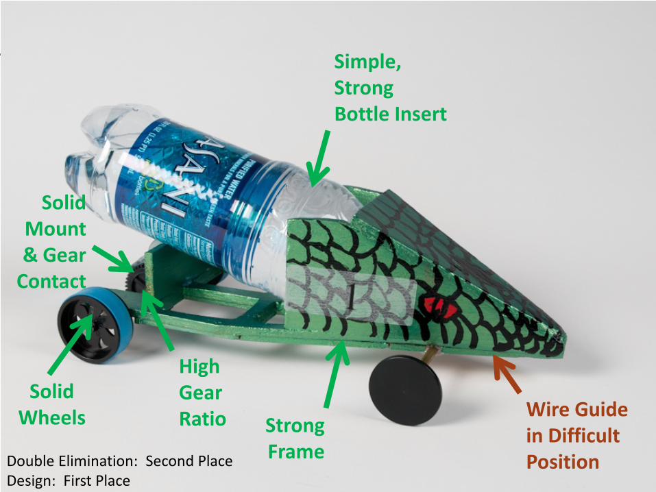
39
Double Elimination: Second Place Design: First Place
Solid Mount & Gear
Contact
Solid Wheels
High Gear Ratio Strong
Frame
Simple, Strong Bottle Insert
Wire Guide in Difficult Position
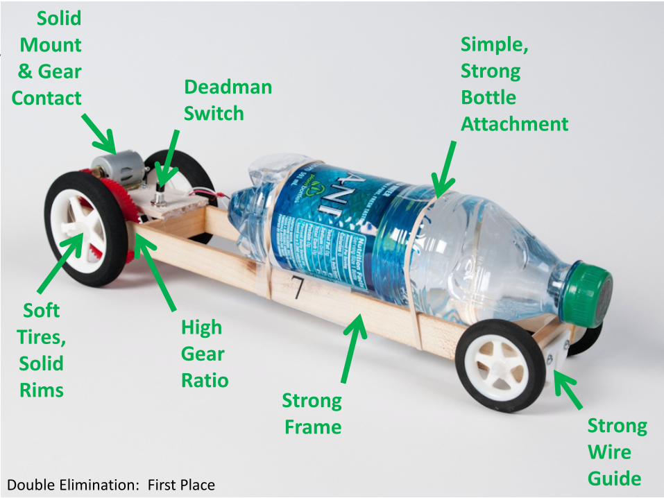
40 Double Elimination: First Place
Solid Mount & Gear
Contact
Soft Tires, Solid Rims
Deadman Switch
High Gear Ratio
Strong Frame
Simple, Strong Bottle Attachment
Strong Wire Guide

41
42
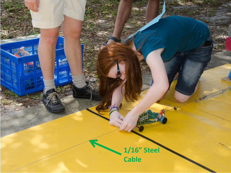
1/16” Steel Cable

43
44

45

46

47

Good Luck!