nanorobot architecture for medical target identification · ioppublishing nanotechnology...
TRANSCRIPT
IOP PUBLISHING NANOTECHNOLOGY
Nanotechnology 19 (2008) 015103 (15pp) doi:10.1088/0957-4484/19/01/015103
Nanorobot architecture for medical targetidentification
Adriano Cavalcanti1,2, Bijan Shirinzadeh2,Robert A Freitas Jr3 and Tad Hogg4
1 CAN Center for Automation in Nanobiotech, Melbourne VIC 3168, Australia2 Robotics and Mechatronics Research Laboratory, Department of Mechanical Engineering,
Monash University, Clayton, Melbourne VIC 3800, Australia3 Institute for Molecular Manufacturing, Pilot Hill, CA 95664, USA4 Hewlett-Packard Laboratories, Palo Alto, CA 94304, USA
E-mail: [email protected]
Received 30 March 2007, in final form 17 October 2007
Published 29 November 2007
Online at stacks.iop.org/Nano/19/015103
Abstract
This work has an innovative approach for the development of nanorobots with sensors for
medicine. The nanorobots operate in a virtual environment comparing random, thermal and
chemical control techniques. The nanorobot architecture model has nanobioelectronics as the
basis for manufacturing integrated system devices with embedded nanobiosensors and
actuators, which facilitates its application for medical target identification and drug delivery.
The nanorobot interaction with the described workspace shows how time actuation is improved
based on sensor capabilities. Therefore, our work addresses the control and the architecture
design for developing practical molecular machines. Advances in nanotechnology are enabling
manufacturing nanosensors and actuators through nanobioelectronics and biologically inspired
devices. Analysis of integrated system modeling is one important aspect for supporting
nanotechnology in the fast development towards one of the most challenging new fields of
science: molecular machines. The use of 3D simulation can provide interactive tools for
addressing nanorobot choices on sensing, hardware architecture design, manufacturing
approaches, and control methodology investigation.
(Some figures in this article are in colour only in the electronic version)
1. Introduction
This paper presents the architecture and the simulation
of nanorobots using sensor capability for medical target
identification. Nanorobots are expected to enable significant
new methodologies in diagnosis, medical therapies, and
minimally invasive surgery [1–4]. In our work we demonstrate
a computational and analytical new approach to help in the
research and development of nanorobots [5, 6].
A first series of nanotechnology prototypes for molecular
machines are being investigated in different ways [2, 7–12],
and some interesting device propulsion and sensing approaches
have been presented [13–16]. Some work has been done in
2D on cellular automata with the examination of collective
behaviors of large numbers of robots to locate specific types of
tissue [17]. More complex molecular machines, or nanorobots,
having embedded nanoscopic features may provide broad
advances on health care sector [18–23]. Through the use
of nanotechnology techniques [24], advances on genetics
and biomolecular computing [25], biological nanorobots can
be applied to advance medicine [26]. For example, in
microbiology engineering the construction of digital circuits
in living cells has been demonstrated [27]. Bacteria have
been used as physical system components [28], and radio
remote control of biological processes has been demonstrated
experimentally [29]. Some proposals on rigid materials
with positional mechanosynthesis [30, 31], and manufacturing
nanodevices were presented [7, 13, 32]. Recent developments
in biomolecular computing have demonstrated the feasibility
of biocomputers [33], a promising first step toward future
nanoprocessors. Other examples include studies of building
biosensors and nanokinetic devices [7, 8, 13, 19, 34].
Real time three-dimensional (3D) prototyping and sim-
ulation are important tools for nanotechnology development.
0957-4484/08/015103+15$30.00 © 2008 IOP Publishing Ltd Printed in the UK1
Nanotechnology 19 (2008) 015103 A Cavalcanti et al
Such tools have significantly helped the semiconductor in-
dustry to achieve faster VLSI (very large scale integration)
development [35]. It should similarly have a direct impact
on the implementation of nanomanufacturing techniques and
also on nanoelectronics progress [36]. Simulation can antic-
ipate performance and help in new device design and manu-
facturing [37, 38], nanomechatronics control design and hard-
ware implementation [8, 39]. The use of scientific visualiza-
tion is a powerful tool for the purpose of designing devices
at nanoscale [40]. In our work, the focus of interaction and
sensing with nanorobots is addressed giving details on the
workspace chemical and thermal signals dispersion through a
3D environment as a testbed for prototyping and analysis. The
nanorobots must search proteins in a dynamic virtual environ-
ment and use different strategies to identify and bring those
proteins for medical delivery.
2. Motivation
Considering the properties of nanorobots to navigate as
bloodborne devices, they can help important treatment
processes of complex diseases in early diagnosis and
smart drug delivery [41]. A nanorobot can provide
efficient early diagnosis of cancer and help with smart
chemotherapy for drug delivery. Nanorobots as drug
carriers for timely dosage regimens allows maintaining the
chemical compounds for a longer time as necessary into the
bloodstream circulation, providing predicted pharmacokinetic
parameters for chemotherapy in anti-cancer treatments [42].
It avoids the current resulting extravasations towards non-
reticuloendothelial-located cancers with the high degenerative
side-effects during chemotherapeutic process [43]. Nanorobots
with chemical nanobiosensors can be programmed to detect
different levels of E-cadherin and beta-catenin as medical
targets in primary and metastatic phases [44–46], helping target
identification and drug delivery.
In terms of diagnosis, a critical issue in cerebral aneurysm
is to detect and locate vessel dilation, if possible before
a subarachnoid hemorrhage occurs. Similarly, nanorobots
using chemical sensors as embedded nanoelectronics can be
programmed to detect different levels of nitric oxide synthase
(NOS) pattern signals as medical targets in early stages
of aneurysm development [47]. Integrated nanobiosensors
and radio frequency (RF) wireless communication [8] can
be utilized for such a task in order to find changes of
gradients for NOS concentrations [48]. Chemical signals
can also be useful for nanorobot medical target identification
and actuation in another cerebral treatment. The amyloid-
β protein deposits show changes on gradients as a symptom
of Alzheimer disease [49, 50]. This information serves
for the early diagnosis of Alzheimer disease and to guide
possible immunotherapy treatments, with more efficient
neurotransmitters delivery, like dopamine and amino acids
such as g-aminobutyrate (GABA), with better medical
administration. Nanorobots can use such signals to delivery
genomic improved myelin basic protein [51], avoiding neurons
to be attacked by the immune system providing better electric
pulses between the nervous system and the muscles.
3. Medical nanorobotics
The feasibility of advancing techniques for control [5] and
manufacturing molecular machines should be understood
as emergent results from actual and upcoming stages of
nanotechnology, based on nanoelectronics [8, 52], new
materials [53–55] and genomics research [56]. New
possibilities are coming from these developments which will
enable new medical procedures [1, 18, 21, 26, 53, 57].
The nanorobot proposed prototyping must be equipped
with the necessary devices for monitoring the most important
aspects of its operational workspace. For biomedical
application the temperature, concentration of chemicals in
the blood, and electromagnetic signatures are some of the
relevant parameters when monitoring the human body to detect
some diseases [58, 59]. The application of new materials
has demonstrated a large range of possibilities for use in
manufacturing better sensors and actuators with nanoscale
sizes [14, 35]. This downscaling will continue, according to the
Semiconductor Industry Association’s roadmap. By 2016, high
performance ICs will contain more than 8.8 billion transistors
in a 280 mm2 area—more than 25 times as many as on today’s
chips built with 130 nm (nanometers) feature sizes [60]. Those
developments allied with 3D simulation should facilitate the
manufacturing design of nanorobots with integrated embedded
nanoelectronics and circuits.
4. Background
Current developments in nanoelectronics [36] and nanobiotech-
nology [61] is providing feasible development pathways to en-
able molecular machine manufacturing, including embedded
and integrated devices which can comprise the main sensing,
actuation, data transmission, remote control uploading, and
coupling power supply subsystems addressing the basics for
operation of medical nanorobots.
A recent actuator with biologically-based components has
been proposed [62]. This actuator has a mobile member
that moves substantially linearly as a result of a biomolecular
interaction between biologically-based components within
the actuator. Such actuators can be utilized in nanoscale
mechanical devices to pump fluids, open and close valves, or
to provide translational movement.
To help control the nanorobot’s position, a system for
tracking an object in space can comprise a transponder device
connectable to the object. The transponder device has one
or several transponder antennas through which a transponder
circuit receives an RF signal. The transponder device adds
a known delay to the RF signal thereby producing an RF
response for transmitting through the transponder antenna [63].
A series of several transmitters and antennas allow a position
calculator associated with the transmitters and receivers to
calculate the position of the object as a function of the known
delay and the time period between the emission of the RF
signal and the reception of the RF response from the first,
second and third antennas.
Nanotechnology is moving fast towards nanoelectronics
fabrication. Chemically assembled electronic nanotechnology
2
Nanotechnology 19 (2008) 015103 A Cavalcanti et al
provides an alternative to using a complementary metal oxide
semiconductor (CMOS) for constructing circuits with feature
sizes in the tens of nanometers [64]. A CMOS component
can be configured in a semiconductor substrate as part of the
circuit assembly [65]. An insulating layer is configured on the
semiconductor substrate, which covers the CMOS component.
A nanoelectronic component is configured above the insulating
layer. If several nanoelectronic components are provided, they
are preferably grouped in nanocircuit blocks.
Biosensors are used to incorporate living components,
including tissues or cells which are electrically excitable
or are capable of differentiating into electrically excitable
cells, and which can be used to monitor the presence or
level of a molecule in a physiological fluid [66]. CNTs
(carbon nanotubes) and DNA (deoxyribonucleic acid) are
recent candidates for new forms of nanoelectronics [67]. These
are combined to create new genetically programmed self-
assembling materials for facilitating the selective placement
of CNTs on a substrate by functionalizing CNTs with
DNA. Through recombinant DNA technology, targets labeled
with distinct detectable biomarkers can be defined, such as
fluorescent labels, enzyme labels, and radioactive patterns, and
employed in suitable biomolecular transducers [56].
5. Medical nanorobot architecture
The main parameters used for the medical nanorobot
architecture and its control activation, as well as the
required technology and current developments that can lead to
manufacturing hardware for molecular machines, are described
next.
5.1. Manufacturing technology
The ability to manufacture nanorobots can be understood
as the result of current trends and new methodologies in
fabrication, computation, transducers and manipulation. The
hardware architecture for a medical nanorobot must include
the necessary devices for monitoring the most important
aspects of its operational workspace: the human body.
To reach this aim, data processing, energy supply, and
data transmission capabilities should be addressed through
embedded integrated circuits, using advances in technologies
derived from nanotechnology and VLSI design [35]. CMOS
VLSI design using extreme ultraviolet lithography provides
high precision and a commercial way for manufacturing early
nanodevices and nanoelectronics systems [68]. To validate
designs and to achieve a successful implementation, the use of
VHDL (very high speed integrated circuit hardware description
language) has become the most common methodology utilized
in the integrated circuit manufacturing industry [69].
A large set of different chemical and biological sensors
has been achieved with distinct sequences of peptides through
combinatorial chemistry for selective detection of various
medical targets. For example, nanobiosensors and fabrication
processes on nanoelectronics have been investigated and
established to achieve electrochemical activation at nanoscale
environment [70, 71]. A post-integrated-circuit assembly
of the nanostructures was also implemented [72], presenting
a layout for analog digital readout, signal processing, and
communications circuitry. It used a CMOS nanowire
integrated circuit with low voltage for biological sensing.
Another recent study has also demonstrated that IC CMOS-
based nanobiosensor with an architecture using nanogaps of
200 nm length is efficiently used to detect biomolecules by
means of voltage changes [73]. To achieve a higher sensitivity,
biomolecules are immobilized in the electrically operated gate
with flow of charge through the semiconducting channel.
Similarly, following principles of integrated nanoelectronics
and molecular organic compounds, a medical diagnostic
nanosensor was recently presented [74]. The device can be
used under in vivo as well as in vitro conditions. It achieves
nanometer scale spatial resolution and provides accurate real
time information regarding not only the concentration of a
specific analyte of organic or inorganic nature but also its
spatial distribution.
5.2. Chemical sensor
Manufacturing silicon-based chemical and motion sensor
arrays using a two-level system architecture hierarchy has been
successfully conducted in the last 15 years [75]. Applications
range from automotive and chemical industry with detection
of air to water element pattern recognition through embedded
software programming, and biomedical uses. Through the
use of nanowires, existing significant costs of energy demand
for data transfer and circuit operation can be decreased by
up to 60% [76]. CMOS-based sensors with nanowires as
material for circuit assembly can achieve maximal efficiency
for applications regarding chemical changes, enabling new
medical applications [25, 57].
Sensors with suspended arrays of nanowires assembled
into silicon circuits can drastically decrease self-heating and
thermal coupling for CMOS functionality [77]. Factors
like low energy consumption and high sensitivity are among
some of the advantages of nanosensors. Nanosensor
manufacturing array processes can use electrofluidic alignment
to achieve integrated CMOS circuit assembly as multi-element
systems [76]. Passive and buried electrodes can be used
to enable cross-section drive transistors for signal processing
circuitry readout. The passive and buried aligned electrodes
must be electrically isolated to avoid the loss of processed
signals.
Some limitations to improving BiCMOS, CMOS and
MOSFET actuators methodologies include quantum-
mechanical tunneling for operation of thin oxide gates, and
subthreshold slope [78]. Surpassing expectations, the semicon-
ductor branch nevertheless has moved forward to keep circuit
capabilities advancing. Smaller channel length and lower volt-
age circuitry for higher performance are being achieved with
new materials aimed to attend the growing demand for high
complex VLSIs. New materials such as a strained channel
with a relaxed SiGe (silicon–germanium) layer can reduce self-
heating and improve performance [79]. Recent developments
in 3D circuits and FinFETs (fin-shaped field effect transis-
tor) double-gates have achieved astonishing results. To further
3
Nanotechnology 19 (2008) 015103 A Cavalcanti et al
advance manufacturing techniques, silicon-on-insulator (SOI)
technology has been used to assemble high performance logic
sub 90 nm circuits [80, 81]. Circuit design approaches to solve
problems with bipolar effect and hysteretic variations based on
SOI structures have been demonstrated successfully [79]. Cur-
rently feasible 90 and 45 nm CMOS devices represent break-
through technology devices that are already being utilized in
products. By 2016 these devices are expected to achieve 22 nm
functionality.
5.3. Temperature sensor
Integrated nanothermoelectric sensors can be implemented as
CMOS devices with promising uses for pattern identifica-
tion [21]. Such an approach should permit a large produc-
tion of infrared thermal sensors applied to different ranges of
wavelength [82]. Nanorobots using temperature sensors open
new medical possibilities for clinical diagnosis, as well as for
ubiquitous data collection, with pervasive patient monitoring.
CMOS as a thermoelectric sensor has the advantage of linear
self-generated response with system integration without requir-
ing bias or temperature stabilization [83]. Thus the infrared ar-
ray could be integrated on a single chip within amplifiers and
signal processing capabilities. Such an approach also allows
a fast pace towards miniaturization with no loss of efficiency
due to electromagnetic noise [82, 84]. CMOS can be oper-
ated at very low voltage levels, which is also a positive as-
pect, presenting good functionality and requiring little energy
for nanorobots. Cantilever and bridge types are also valid tech-
niques for possible different ways to implement CMOS ther-
moelectric sensors.
Nanowires are suitable for fabricating CMOS integrated
devices [85]. CNTs are able to improve performance with
low power consumption for nanosensors. Its particular high
precision makes it quite useful for applications in infrared
supersensitive biosensors, with applications such as target
oriented temperature detection, and measurement in changes
of body temperature. Nanosensors present important electrical
properties, high thermal conductance and fast frequency
response [14, 86]. The power consumption with NEMS
(nano electro-mechanical systems) is three times lower if
compared with traditional MEMS (micro electro-mechanical
systems) thermal sensors, where for MEMS the operating
values range in terms of mW [83]. Nanowires can be
configured as two-terminal devices electrically designed to
work as high or low resistance diodes. Crossed nanowire p–n
junctions can function successfully as logic gates from crossed
nanowire field effect transistors [85]. Therefore, microwire
pitch incorporated in actual CMOS integrated designs can be
reduced to the nanowire pitch by using on–off masks aligned
diagonally to produce a one-to-one microwire to nanowire
correspondence.
5.4. Actuator
There are different kinds of actuators, such as electromagnetic,
piezoelectric, electrostatic, electrothermal, where they should
be utilized depending on the aim and the workspaces where
they will be applied [87]. A flagella motor has been quoted
quite frequently as an example for a kind of biologically
inspired actuator for molecular machine propulsion [88].
Adenosine triphosphate, also known in short as ATP, is equally
used as an alternative for nanomotors [7]. DNA and RNA
(ribonucleic acid) prototypes were also proposed for designing
different types of devices.
A set of fullerene structures were presented for
nanoactuators [89]. The use of CNTs as conductive structures
permits electrostatically driven motions providing the forces
necessary for nanomanipulation. CNTs can be used as
materials for commercial applications on building devices and
nanoelectronics such as nanotweezers and memory systems.
SOI technology has been used for transistors with high
performance, low heating and energy consumption for VLSI
devices. CNT self-assembly and SOI properties can be
combined to address CMOS high performance on design and
manufacturing nanoelectronics and nanoactuators [90]. Owing
to the maturity of silicon CMOS technology, as well as the
unique properties of CNTs, the integration of CNT and CMOS
technology makes use of the advantages of both [91].
For a medical nanorobot, the use of CMOS as an actuator
based on biological patterns and CNTs should be considered a
natural choice. In the same way DNA can be used for coupling
energy transfer [29, 92], and proteins may serve as basis for
ionic flux with electrical discharge ranges from 50 to 70 mV
dc voltage gradients in the cell membrane [93]; an array format
based on CNTs and CMOS techniques could be used to achieve
nanomanipulators as an embedded system for integrating the
future architecture of molecular machines [36, 94]. Ion
channels can interface electrochemical signals using sodium
for the energy generation which is necessary for mechanical
actuators operation [93]. Actuators built as nanodevices can
be programmed to perform different manipulations, enabling
the nanorobot to directly interact with the molecular operating
environment.
5.5. Energy supply
The most effective way to keep the nanorobot operating
successfully is to establish the use of a continuous available
source of power. The energy must be available and delivered
to the nanorobot while it is performing predefined tasks in the
operational environment. For a medical nanorobot, this means
that the device has to keep working inside the human body,
sometimes for long periods, and requires easy access to clean
and controllable energy to maintain efficient operation.
Some possibilities to power the nanorobot can be provided
from ambient energy [1]. Temperature displacements could
likewise generate useful voltage differentials. Cold and
hot fields from conductors connected in series can also
produce energy using the well-established Seebeck effect.
Electromagnetic radiation from light is another option for
energy generation in determined open environments [95] but
not for in vivo medical nanorobotics. Kinetic energy can
be generated from the bloodstream due to motion interaction
with designed devices embedded with the nanorobot [96], but
this kinetic process would demand costly room within the
nanorobot hardware architecture.
4
Nanotechnology 19 (2008) 015103 A Cavalcanti et al
Most recently, remote inductive powering has been used
both for RFID (radio frequency identification device) and
biomedical implanted devices to supply power on the order
of milliwatts [97–99]. A low frequency energy source can
be sufficient to operate nanorobots. This functional approach
presents the possibility of supplying energy in a wireless
manner [97]. Thus, it enables one to operate sensors and
actuators necessary for the controlled operation of nanorobots
inside the human body.
The use of CMOS for active telemetry and power supply
is the most effective and secure way to ensure energy
as long as necessary to keep the nanorobot in operation.
The same technique is also appropriate for other purposes,
like digital bit encoded data transfer from inside a human
body [100]. Therefore nanocircuits with resonant electric
properties can operate as a chip providing electromagnetic
energy supplying 1.7 mA at 3.3 V for power, allowing the
operation of many tasks with few or no significant losses during
transmission [101]. RF-based telemetry procedures have
demonstrated good results in patient monitoring and power
transmission through inductive coupling [97, 98, 102, 103],
using well-established techniques already widely present in
commercial applications of RFID [104]. The energy received
can also be saved in the range of ∼1 µW while the nanorobot
stays in inactive modes, just becoming active when signal
patterns require it to do so. Some typical nanorobotic tasks
may require the device only to spend low power amounts, once
it has been strategically activated. For communication, sending
RF signals ∼1 mW is required. Allied with the power source
devices, the nanorobots need to perform precisely defined
actions in the workspace using available energy resources as
efficiently as possible.
A practical way to achieve easy implementation of this
architecture will be to obtain both energy and data transfer
capabilities for nanorobots by employing a mobile phone in
such process [105]. The cellular phone should be uploaded
with the control software that includes the communication and
energy transfer protocols.
5.6. Data transmission
The application of devices and sensors implanted inside the
human body to transmit data about the health of patients can
provide great advantages for biomedical problems [106, 107].
Most recently, the use of RFID for in vivo data collecting
and transmission was successfully tested for electroencephalo-
grams [101]. For communication in liquid workspaces, de-
pending on the application, acoustic, light, RF, and chemi-
cal signals can be considered as possible choices for commu-
nication and data transmission [2]. Chemical signaling and
sensor-based behaviour are quite useful for nearby communi-
cation among nanorobots for some teamwork coordination and
biomedical instrumentation [5, 6, 108]. Acoustic communica-
tion is more appropriate for long distance communication and
detection with low energy consumption as compared to light
communication approaches [109]. Although optical commu-
nication permits faster rates of data transmission, its energy
demand makes it not ideal for nanorobots [1].
Work with RFID has been developed as an integrated
circuit device for medicine [99, 101, 104]. Using integrated
sensors for data transfer is the best answer to read and write
data in implanted devices. Teams of nanorobots should be
equipped with single-chip RFID CMOS-based sensors [110].
CMOSwith submicron SoC (System-on-Chip) design could be
used for extremely low power consumption with nanorobots
communicating collectively for longer distances through
acoustic sensors [111]. For the nanorobot, active sonar
communication frequencies may reach up to 20 µW@ 8 Hz at
resonance rates with 3 V supply [109]. Cell phones are more
widely accepted and usual than a RF CMOS transponders and
can be extremely practical and useful as sensors for acquiring
wireless data transmission from medical nanorobots injected
inside the patient’s body. Such phones can be a good choice
for monitoring predefined patterns for many health problems.
Electromagnetic radio waves are used to command and detect
the current status of nanorobots inside the patient. This occurs
as a transponder device emits a magnetic signature to the
passive CMOS sensors embedded in the nanorobot, which
enables sending and receiving data through electromagnetic
fields [103]. The nanorobot data communication converts the
wave propagation generated by the emitting signal through a
well defined protocol. From the last set of events recorded
in pattern arrays, information can be reflected back by wave
resonance [112]. For nanorobot data transferring ∼4.5 kHz
frequency with approximate 22 µs delays are possible ranges
for data communication.
Frequencies ranging from 1 to 20MHz can be successfully
used for biomedical applications without any damage [101]. A
small loop planar antenna working as an electromagnetic pick-
up with a good matching to the low noise amplifier is used with
the nanorobot.
6. System implementation
Research efforts have recently been directed towards
molecular manufacturing and minimally invasive surgery
[9, 15, 113, 114]. While the assembly of nanodevices is ad-
vancing continuously [53, 57, 115], further investigation on
nanorobots for application in medicine enables significant in-
sights on various aspects such as their operation and hard-
ware architecture, with sensor and actuator designs. The soft-
ware NCD (nanorobot control design) was implemented for
nanorobot modeling. It is a 3D real time virtual environment
useful for architecture analysis, system control design, and in-
teractive simulation. Figure 1 describes the simulated microen-
vironment consisting of a long fluid-filled pipe, with a diameter
of some tens of microns.
6.1. Drug delivery and diagnosis
The clinical use of nanorobots for diagnosis, therapeutic and
surgical purposes should be done with intravenous injection.
Therefore, the nanorobots can be released directly inside the
patient’s bloodstream. The major cancer treatment cycle
for chemotherapy pharmacokinetics includes absorption and
metabolism, plus a break for the body’s re-establishment
5

Nanotechnology 19 (2008) 015103 A Cavalcanti et al
Figure 1. Schematic illustration of the simulated workspace as asection of a longer pipe. The x–z plane contains the obstacles.
before the next chemotherapy session. Patients are normally
treated in cycles of every 2 weeks for small tumors [116]. As an
initial time threshold for medical purpose, nanorobots should
be able to analyze and provide a body diagnosis within one
week through the use of proteomic based sensors. The uptake
kinetics of a low molecular weight using a magnetic resonance
contrast agent can predict the delivery of protein drugs to solid
tumors [117]. Hence, a similar approach is useful to verify in
vivo nanorobot’s biosensor activation through targeted antigen
detection.
After nanorobots cross cellular membranes for targeted
delivery, drug retention in the tumor will determine the
therapeutic efficiency. The chemotherapy is influenced by drug
transfer processes from plasma to tissue in achieving more
effective tumor chemotherapy based on its composition [117].
Thus, the major advantage of nanorobots for cancer drug
delivery is to minimize chemotherapy side effects. As the best
approach, the nanorobot architecture incorporates DNA-CNT
CMOS as a hybrid biosensor with single-chain antigen-binding
proteins [73, 74, 118]. This process uses activation based on
proteomics and bioelectronics signals for medicament release.
Therefore, each time the nanorobot detects predefined changes
of protein gradients, nanoactuators are activated to manipulate
drug delivery.
Changes to chemical and thermal signals are applicable
conditions directly related to major medical target identifica-
tion. Some examples on changing protein concentrations in-
side body near a medical target under pathological circum-
stances are NOS [47], E-cadherin [44] and Bcl-2 [119]. More-
over, a change of temperature normally occurs for inflamed
tissues [120]. The model incorporates chemical and thermal
parameters as clinically and therapeutically the most important
guidelines on nanorobot prototyping analysis. The simulation
in a 3D real time environment aims to establish a useful frame-
work as a testbed for nanorobot foraging inside the body. Then,
the considered therapeutic use of nanorobots includes cancer
and intracranial treatments. This study provides a methodolog-
ical approach that helps in the development of nanorobotics
for medical target identification. Hence, chemical and thermal
signals are paramount in this regard.
Figure 2. Nanorobots’ design-sensors, molecular sorting rotors, finsand propellers. The depicted blue cones shows the sensors ‘touching’areas.
Figure 3. Organ-inlet is being assisted by the nanorobot withdelivery of proteins.
6.2. Nanorobot interaction
Nanorobots can move with six-degrees-of-freedom, i.e.,
arbitrary translation and rotation fins and propellers (figure 2).
They also have specific sensory capabilities to detect the target
regions, obstacles and chemicals relevant for their medical
application. We studied a prototypical task for nanorobots:
moving through a fluid-filled vessel to locate target regions
through thermal and chemical signals. The simulator allows
the examination of a variety of control algorithms. Nanorobot
behavior based on random motion and detection of chemical
gradients is useful for medical target identification and drug
delivery [121].
The simulator does allow multiple nanorobots to operate
independently and in a cooperative mode. As one use for
this capability, it is possible to investigate the robustness of
control techniques by observing the mean time required for the
interaction with the environment for the drug targets (figure 3).
The nanorobot has to detect and locate any medical target,
represented as organ-inlets, demanding protein injection in a
period of time for the simulated dynamic scenery.
6.3. Diffusing signals
The 3D environment contains nanorobots, obstacles,
biomolecules and specific medical targets. The medical
6
Nanotechnology 19 (2008) 015103 A Cavalcanti et al
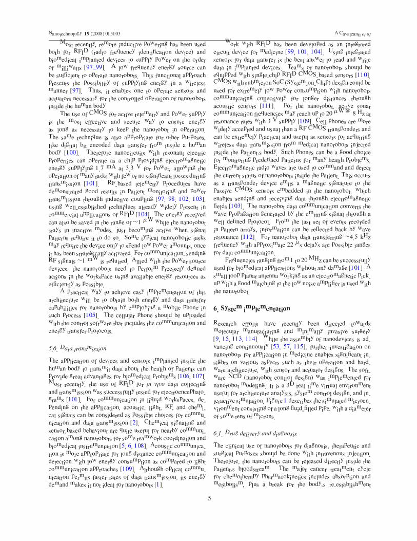
Figure 4. Virtual environment, top camera view.
targets represent organ-inlets, displaced stochastically as target
locations or drug delivery points for medical applications (fig-
ure 4). These organ-inlets are closed when the chemical con-
centrations are near the desired levels. Otherwise, it will open
diffusing chemical and thermal signals to show the required
injection of protein drugs. A key choice in chemical signaling
is the measurement time and detection threshold at which the
signal is considered to be received [122]. Due to background
concentration, some detection occurs even without the target
signal. As a threshold, we use the diffusive capture rate φ for a
sphere of radius R in a region with concentration as:
φ = 4πDRC (1)
where the concentration for other shapes such as cylinders
are about the same [121]. All moving objects (i.e., the
nanorobots and biomolecules) in the workspace have neutral
buoyancy. In regard to the circulatory system about vessels
geometries and the nanorobot sizes for medical purposes, the
lumen diameters ranges from the vena cava with ∼3 cm in
the heart, to ∼10 µm of capillary vessels. The simulated
nanorobot has a size of 3 µm3, which comprises 2 µm3 with
embedded nanobioelectronics as described in the nanorobot
architecture [8], and 1 µm3 as inside space for transporting
substances for medical delivery. In the present study the
nanorobot is transporting proteins.
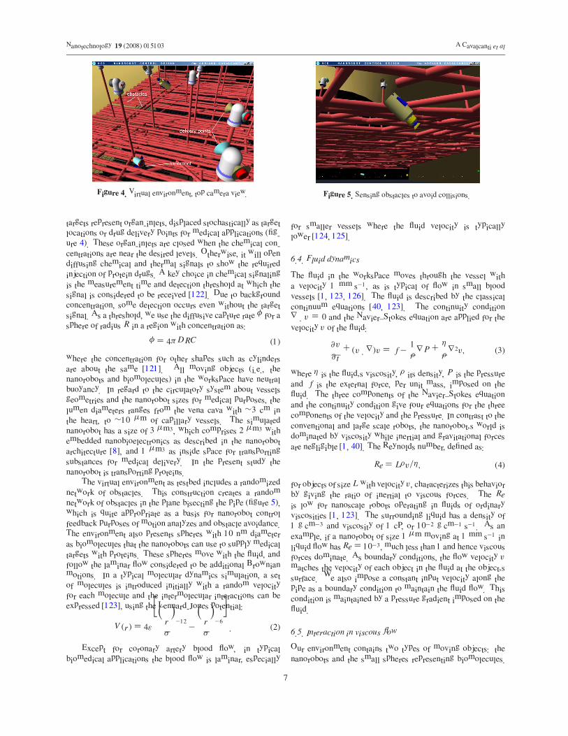
The virtual environment as testbed includes a randomized
network of obstacles. This construction creates a random
network of obstacles in the plane bisecting the pipe (figure 5),
which is quite appropriate as a basis for nanorobot control
feedback purposes of motion analyzes and obstacle avoidance.
The environment also presents spheres with 10 nm diameter
as biomolecules that the nanorobots can use to supply medical
targets with proteins. These spheres move with the fluid, and
follow the laminar flow considered to be additional Brownian
motions. In a typical molecular dynamics simulation, a set
of molecules is introduced initially with a random velocity
for each molecule and the intermolecular interactions can be
expressed [123], using the Lennard-Jones potential:
V (r) = 4ε
�
� r
σ
�−12
−� r
σ
�−6�
. (2)
Except for coronary artery blood flow, in typical
biomedical applications the blood flow is laminar, especially
Figure 5. Sensing obstacles to avoid collisions.
for smaller vessels where the fluid velocity is typically
lower [124, 125].
6.4. Fluid dynamics
The fluid in the workspace moves through the vessel with
a velocity 1 mm s−1, as is typical of flow in small blood
vessels [1, 123, 126]. The fluid is described by the classical
continuum equations [40, 123]. The continuity condition
∇ · v = 0 and the Navier–Stokes equation are applied for the
velocity v of the fluid:
∂v
∂ t+ (v · ∇)v = f −
1
ρ∇P +
η
ρ∇2v, (3)
where η is the fluid’s viscosity, ρ its density, P is the pressure
and f is the external force, per unit mass, imposed on the
fluid. The three components of the Navier–Stokes equation
and the continuity condition give four equations for the three
components of the velocity and the pressure. In contrast to the
conventional and large scale robots, the nanorobot’s world is
dominated by viscosity while inertial and gravitational forces
are negligible [1, 40]. The Reynolds number, defined as:
Re = Lρv/η, (4)
for objects of size L with velocity v, characterizes this behavior
by giving the ratio of inertial to viscous forces. The Re
is low for nanoscale robots operating in fluids of ordinary
viscosities [1, 123]. The surrounding liquid has a density of
1 g cm−3 and viscosity of 1 cP, or 10−2 g cm−1 s−1. As an
example, if a nanorobot of size 1 µm moving at 1 mm s−1 in
liquid flow has Re = 10−3, much less than 1 and hence viscous
forces dominate. As boundary conditions, the flow velocity v
matches the velocity of each object in the fluid at the object’s
surface. We also impose a constant input velocity along the
pipe as a boundary condition to maintain the fluid flow. This
condition is maintained by a pressure gradient imposed on the
fluid.
6.5. Interaction in viscous flow
Our environment contains two types of moving objects: the
nanorobots and the small spheres representing biomolecules.
7
Nanotechnology 19 (2008) 015103 A Cavalcanti et al
These objects are subject to both deterministic and random
forces. The deterministic forces arise from the fluid motion
and, in the case of the nanorobots, from their powered
locomotion.
The inertial force on the object of size L moving with
velocity v with respect to the fluid is of the order Finertial ∼=ρv2L2 and the viscous drag force is of the order Fviscous ∼=ηvL. Thus to keep moving, a nanorobot of size L ∼= 1 µm
and velocity v ∼= 1 mm s−1 with respect to the fluid must apply
Finertial ∼= 1 fN (femtonewtons, 1 fN = 10−15 N) and a much
larger Fviscous ∼= 103 fN of motive force. As a consequence of
this dominance of viscosity, when a force F is applied to an
object, it quickly reaches a terminal velocity where that force
is canceled by the drag from the fluid. As an illustration of this
behavior, if motive power to a swimming spherical nanorobot
with radius L = 1 µm, and the velocity v = 1 cm s−1 with
respect to the fluid, is suddenly stopped, then the nanorobot
will ‘coast’ to a halt with respect to the fluid in a time tcoast as:
tcoast =ρL2
15η= 0.1 µs (5)
and in distance xcoast ∼= vtcoast = 1 nm. A comparable
result applies to other shapes, e.g., the nanorobot and the
smaller sized biomolecules. Thus an applied force quickly
results in motion with constant velocity. It contrasts with
the behavior when inertial forces dominate: an applied force
produces a constant acceleration. A similar observation applies
to rotations: a given torque rapidly produces a constant angular
velocity rather than a constant angular acceleration.
Two main forces act on a nanorobot while it is not in
contact with other objects. First is the force Fr produced by
the robot itself, which is taken to be directed along the axis of
the cylinder. Second is the drag from the fluid given by:
Fdrag = −AdragηLv, (6)
where v is the velocity vector of the nanorobot with respect to
the fluid, v = vrobot − vfluid. The quantity Adrag is a geometric
factor depending on the orientation of the nanorobot with
respect to the fluid and is typically of order 1, e.g., for a sphere
of diameter L, Adrag is 3π when no other objects are nearby.
For other situations, Adrag has roughly the same magnitude,
but the exact value must be determined numerically. To see
how this is done, consider a small area dA on the surface
of an object, treated as a vector oriented perpendicular to the
surface. The fluid imposes a force vector −T dA on that area,
where T is a matrix representing the stress tensor for the fluid
motion at the surface of the object. For incompressible fluids,
its components are expressed:
Tk,l = Pδk,l − η
�
∂vk
∂xl+
∂vl
∂xk
�
, (7)
where is δk,l = 1 when k = l and is 0 otherwise.
In general, the velocity gradient and pressure vary over the
surface of the object. The total drag force requires integrating
the force on each part of the object. The difference in forces
around the object can also give rise to a torque, causing the
object to rotate as it moves through the fluid. The total force
acting on the robot is Fr + Fdrag, which is zero when the
nanorobot velocity equals to:
vrobot = vfluid + Fr/(AdragηL). (8)
The biomolecules move passively along with the fluid, i.e.,
their velocity is equal to vfluid. Both the passive obstacles
and other nanorobot are potential sources of collision and
additional force. In particular, a collision with the wall of the
pipe or one of the obstacles sets to zero the component of the
object’s velocity perpendicular to the wall or obstacle. When
a biomolecule collides with a nanorobot, the biomolecule
velocity perpendicular to the robot is set to zero; it may also
be absorbed by the robot if it was identified as a protein. In
addition to these deterministic forces, stochastic forces due to
thermal motion of molecules in the fluid give rise to additional
randommotions, i.e., Brownian motion. As an indication of the
size of these motions, the average displacement of a particle of
radius L over a time t when the fluid has temperature T is:
b =�
kT t
3πηL
�1/2
, (9)
where k is Boltzmann’s constant and b is displacement.
Operating at typical body temperature, this gives displacement
for the nanorobot of about√t µm when t is measured in
seconds, and 8√t µm for the biomolecules.
Collecting biomolecules is part of the robot’s task. A
nanorobot at rest with respect to the fluid will encounter
biomolecules due to their diffusion. The laminar fluid flow
itself only moves the molecules along streamlines which go
through the workspace. An estimate of the rate at which such
a nanorobot will encounter diffusing biomolecules is of order
10LDC , where L is the size of the robot (3 µm3), D is the
diffusion coefficient in liquid, about 10−10 m2 s−1, and C is
the concentration of molecules around the robot [1]. In the
simulation, C = 1016 m−3 enabling the nanorobots to have
an interactive response in collecting them for a further target
identification, and protein drug delivery. In our simulation, the
collisions between biomolecules and the robots are determined
from their individual motions, including the diffusion from
Brownian motion.
Our physically based simulation includes kinetics and
frictional aspects for object motion with hydrodynamics at low
Reynolds number [121, 123]. Specifically, the dynamics of
the objects in our environment is determined by the object
positions and, for the nanorobots, their choice of locomotion
force as determined from their control program. Unlike
the case of inertial forces, there is no need to consider
accelerations. The dynamics in the environment is processed as
the boundary conditions for determining the fluid motion from
equation (3). Given the fluid motion, we determine the net
force and torque on each nanorobot, after which equation (8)
gives its new velocity. Each biomolecule’s velocity matches
that of the fluid at its position. For both the nanorobots
and biomolecules, this velocity is also subject to constraints
from any collisions. From the perspective of each object, this
process amounts to a function that evaluates its velocity vobject
8
Nanotechnology 19 (2008) 015103 A Cavalcanti et al
Table 1. Parameters.
Chemical signal
Production rate Q = 104 molecule s−1
Diffusion coefficient D = 100 µm2 s−1
Background concentration 6 × 10⁻³ molecule µm−3
Parameter Nominal value
Average fluid velocity v = 1000 µm s−1
Vessel diameter d = 10, 20, 40 µmWorkspace length L = 60 µmDensity of nanorobots 3 µm3
in terms of the state of the system. Using a time step of �t , we
then update the object positions according to:
object ← F + vobject�t + ε, (10)
where ε is a random vector chosen from a Gaussian distribution
with mean of 0 and average length√
�t µm (with �t
measured in seconds) for the nanorobots and 8 times as large
for the biomolecules. For the nanorobots, a similar evaluation
is based on the torques applied by the fluid, the nanorobots
themselves as part of their locomotion, and any collisions given
their angular velocities. The angular velocity then gives the
change in orientation after the time �t , and r is the applied
force for manipulating an object.
7. Target identification
Nanorobots’ capability for moving, sensing and manipulating
is quite important for interacting with target identification for
treatments of different diseases. Depending on the medical
application, specific choices can be set in terms of sensors and
actuators control.
7.1. Sensing
Based on the described hardware architecture, the nanorobot
uses sensors allowing it to detect and identify nearby large
objects in its environment, as well as the target regions for its
task.
The nanorobot includes external sensors to inform it of
collisions and to identify when it has encountered a chemical
signal or abrupt changes of temperature for targeted areas.
As a practical technique for nanorobots orientation we used
chemical signals as a useful approach for medicine. A
significant rise in temperature may occur every time there is
some abnormality in the human body [58]. In some cases, the
temperature difference at the site of some lesion from the core
temperature can reach up to ∼2 ◦C [20]. Hence, in order to
simulate the nanorobot intervention and interaction with the
workspace, we used different organ-inlets as delivery targets,
where depending on their protein demand, they will be emitting
chemical and thermal signals. We simulated distinct cases to
validate our study given the equation (1) and parameters on
table 1 for diffusing signals.
These changes on chemical concentration will be used
to guide the nanorobots. The nanorobots are able to detect
obstacles over a range of about 4 µm, and within an angular
resolution equivalent to a diameter of 3 µm at that range. The
biomolecules are too small to be detected reliably: instead
the robot relies on chemical contact sensors to detect them.
The sensor capabilities allow the evaluation of the different
sensing actions that the nanorobot can take. How effectively
the nanorobot actuation can be improved is analyzed with
chemical and thermal sensing.
7.2. Actuation
The nanorobot’s task involves collecting various chemical
compounds as predefined proteins, delivering them to specific
target regions in the 3D environment. The nanorobots must,
after identifying the biomolecules as proteins, use control
strategies involving movement around the environment to
identify and reach the organ-inlets requiring protein drug
delivery. For the propulsion mechanism to move through
the fluid, the nanorobot uses double propellers, with different
velocities regarding the flow directions being adjusted. Since
applied forces rapidly result in a terminal velocity through
the fluid, in the simulation of the locomotion mechanism
they produce a given velocity vforce with respect to the fluid
according to equation (8). As described above, these speeds
correspond to forces of the order 103 fN. Thus equation (8)
becomes:
vrobot = vfluid + vforce, (11)
with vforce directed along the axis of the nanorobot and with
one of these three magnitudes.
8. Nanorobot simulation
The simulator maintains a list of positions and orientations of
all objects in the task environment, including the nanorobots.
This list maintains all information relevant to the nanorobot
tasks. It also introduces new biomolecules with the fluid as
it enters the environment. The simulator consists of several
modules, that simulate physical behaviors, determine sensory
information for each nanorobot, run the control programs to
determine the nanorobot actions, provide a visual display of the
environment, and records the history of nanorobot behaviors
for detailed analysis. The computational approach involves a
multithreaded system that provides dynamic updates for the
nanorobot real time sensing and activation (figure 6). This
same concept and implementation is applied in relation to
other nanorobots as well as to the surrounding workspace.
Memory behavior is based on pre-programmed actions and
defined rules, which are activated according to input signals
to trigger the desired actuation.
8.1. Visualization
The development of nanosystems must be able to respond
efficiently in real time for the changing aspects of
microenvironments not previously examined from a control
perspective. Including aspects of the physical environment
in conjunction with graphical visualization provide a feasible
approach for architecture prototyping, control system, and
sensor design analyzes.
9
Nanotechnology 19 (2008) 015103 A Cavalcanti et al
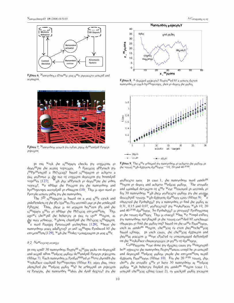
Figure 6. Nanorobot’s dynamic real time interactive sensing andactuation.
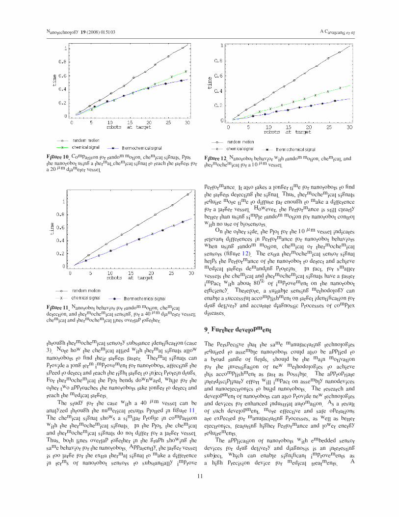
Figure 7. Nanorobots search for organ-inlets demanding proteininjection.
In our work the simulator checks for collisions to
determine the actual velocities. A practical approach for
implementing a physically based simulation to achieve a
fast response is the use of collision detection for bounding
volumes [127]. With this approach to determine the robot
velocity, we update the position for the nanorobots and
biomolecules according to equation (10). This is also used to
provide sensor input for the nanorobot.
The 3D simulation is based on a real time clock and
independent of the fps (frames per second) rate in the rendering
pipeline. Thus, there is no relation between fps and the
simulator timer to update the physical environment. This
allows showing the behavior in fast or slow motion, as
the user requests, without changing the physical simulation.
We used parallel processing techniques [128], where the
nanorobots react adaptively to any stimulus produced by the
environment [129], with the model visualization in real time.
8.2. Numerical results
In our study 30 nanorobots perform similar tasks on detecting
and acting upon medical targets demanding protein injections
(figure 7). Each nanorobot is programmed to move through the
workspace catching biomolecules (figure 8); after that, once
identified the medical target may be requiring an injection
of proteins, the nanorobot makes the drug delivery for the
Nanorobot trajectory
start
collect
nutrients
find target
delivery
0
5
10
15
20
25
30
35
40
x - microns
z -
mic
ron
s
0 10 20 30 40 50 60
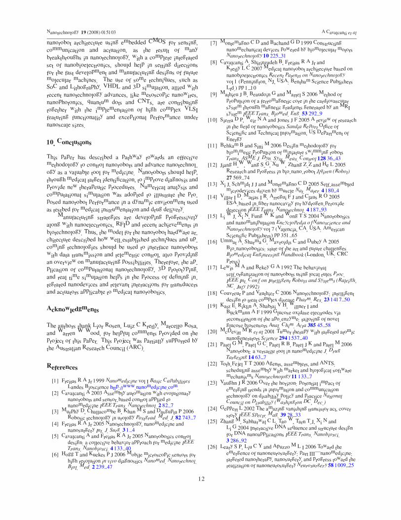
Figure 8. A detailed trajectory performed by a sensor-drivennanorobot to catch biomolecules, then to detect the target.
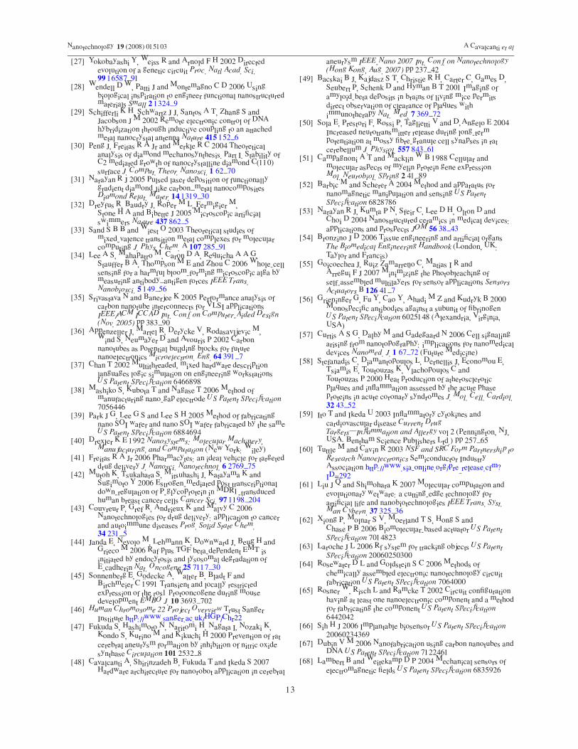
Figure 9. The time required for nanorobots to achieve the targets inthe vessel with different diameters—10, 20 and 40 µm.
respective area. In case 1, the nanorobots used random
motion to detect and achieve medical targets. The average
and standard deviation of time were measured in seconds to
get 30 nanorobots with their respective targets for the results
describing vessels with different diameter sizes (figure 9). We
observed the probability for a nanorobot to find the target as
0.31, 0.15 and 0.07, respectively for workspaces with 10, 20
and 40 µm diameters. So probability is inversely proportional
to the vessel diameter. This is exactly what we would expect
for nanorobots navigating in the vessel crowded by stochastic
obstacles to find the target only based on the same parameters,
such as random motion, chemical or even thermochemical
based signals. In such cases, the chemical diffusion and
thermal reaction is more sprayed or concentrated depending
on the workspace characteristics in terms of diameters.
Comparisons were done for distinct cases for monitoring
how effective the nanorobot performances could be in sensing
and detecting medical targets inside the environment using
different parameters (figure 10). For the 20 µm vessel, this
shows the average time to have 30 nanorobots at medical
targets with behavior guided for random motion (case 1),
sensing chemical signal (case 2), or tracking target location
10
Nanotechnology 19 (2008) 015103 A Cavalcanti et al
Figure 10. Comparison for random motion, chemical signals, plusthe nanorobot using a thermal-chemical signal to reach the targets fora 20 µm diameter vessel.
Figure 11. Nanorobot behavior for random motion, chemicaldetection, and thermochemical sensing, for a 40 µm diameter vessel;chemical and thermochemical lines overlap together.
through thermochemical sensory substance identification (case
3). Note how the chemical allied with thermal signals allow
nanorobots to find their targets faster. Thermal signals can
provide a long term improvement for nanorobots, affecting the
speed to detect and reach the right target to inject protein drugs.
For thermochemical the plot bends downward, while for the
other two approaches the nanorobots take longer to detect and
reach the medical targets.
The study for the case with a 40 µm vessel can be
analyzed through the numerical results plotted in figure 11.
The chemical signal shows a similar profile in comparison
with the thermochemical signals. In the plot, the chemical
and thermochemical signals do not differ for a larger vessel.
Thus, both lines overlap together in the graph showing the
same behavior for the nanorobots. Apparently, the larger vessel
is too large for the extra thermal signal to make a difference
in terms of nanorobot sensors to substantially improve
Figure 12. Nanorobot behavior with random motion, chemical, andthermochemical for a 10 µm vessel.
performance. It also takes a longer time for nanorobots to find
the targets detecting the signal. Thus, thermochemical signals
require more time to diffuse far enough to make a difference
for a larger vessel. However, the performance is still clearly
better than using simple random motion for nanorobot control
with no use of biosensors.
On the other side, the plot for the 10 µm vessel indicates
relevant differences in performance for nanorobot behaviors
when using random motion, chemical or thermochemical
sensors (figure 12). The extra thermochemical sensor signal
helps the performance of the nanorobot to detect and achieve
medical targets demanding proteins. In fact, for smaller
vessels the chemical and thermochemical signals have a faster
impact with about 80% of improvement on the nanorobot
efficiency. Therefore, a suitable sensing methodology can
enable a successful accomplishment on target identification for
drug delivery and accurate diagnostic processes of complex
diseases.
9. Further development
The perspective that the same manufacturing technologies
required to assemble nanorobots could also be applied to
a broad range of fields, should be the main motivation
for the investigation of new methodologies to achieve
this accomplishment as fast as possible. The appropriate
interdisciplinary effort will impact on assembly nanodevices
and nanoelectronics to build nanorobots. The research and
development of nanorobots can also provide new technologies
and devices for enhanced industrial automation. As a result
of such development, more effective and safe operations
are expected for manufacturing processes, as well as better
electronics, featuring higher performance and lower energy
requirements.
The application of nanorobots with embedded sensor
devices for drug delivery and diagnosis is an interesting
subject, which can enable significant improvements as
a high precision device for medical treatments. A
11
Nanotechnology 19 (2008) 015103 A Cavalcanti et al
nanorobot architecture using embedded CMOS for sensing,
communication and actuation, as the result of many
breakthroughs in nanotechnology, with a complete integrated
set of nanobioelectronics, should help in setting directions
for the fast development and manufacturing designs of future
molecular machines. The use of some techniques, such as
SoC and Lithography, VHDL and 3D simulation, allied with
recent nanotechnology advances, like mesoscopic nanowires,
nanophotonics, quantum dots and CNTs, are contributing
together with the implementation of high complex VLSI
featuring functionality and exceptional performance under
nanoscale sizes.
10. Conclusions
This paper has described a pathway towards an effective
methodology to control nanorobots and advance nanotechnol-
ogy as a valuable tool for medicine. Nanorobots should help,
through medical target identification, to improve diagnosis and
provide new therapeutic procedures. Numerical analysis and
computational simulation was adopted to illustrate the pro-
posed nanorobot performance in a dynamic environment used
as testbed for medical instrumentation and drug delivery.
Manufacturing strategies are developing progressively
along with nanoelectronics, RFID and recent achievements in
biotechnology. Thus, the model for the nanorobot hardware ar-
chitecture described how well-established techniques and up-
coming technologies should be used to interface nanorobots
with data transmission and telemetric control, also providing
an overview on manufacturing possibilities. Therefore, the ap-
plication of computational nanotechnology, 3D prototyping,
and real time simulation helps in the process of defining in-
tegrated nanodevices and relevant interactions for transducers
and actuators applicable to medical nanorobotics.
Acknowledgments
The authors thank Lior Rosen, Luiz C Kretly, Marcello Rosa,
and Warren W Wood, for helpful comments provided on the
project of this paper. This project was partially supported by
the Australian Research Council (ARC).
References
[1] Freitas R A Jr 1999 Nanomedicine vol I Basic CapabilitiesLandes Bioscience http://www.nanomedicine.com.
[2] Cavalcanti A 2003 Assembly automation with evolutionarynanorobots and sensor-based control applied tonanomedicine IEEE Trans. Nanotechnol. 2 82–7
[3] Murphy D, Challacombe B, Khan M S and Dasgupta P 2006Robotic technology in urology Postgrad. Med. J. 82 743–7
[4] Freitas R A Jr 2005 Nanotechnology, nanomedicine andnanosurgery Int. J. Surg. 3 1–4
[5] Cavalcanti A and Freitas R A Jr 2005 Nanorobotics controldesign: a collective behavior approach for medicine IEEETrans. Nanobiosci. 4 133–40
[6] Hogg T and Kuekes P J 2006 Mobile microscopic sensors forhigh resolution in vivo diagnostics Nanomed. Nanotechnol.Biol. Med. 2 239–47
[7] Montemagno C D and Bachand G D 1999 Constructingnanomechanical devices powered by biomolecular motorsNanotechnology 10 225–31
[8] Cavalcanti A, Shirinzadeh B, Freitas R A Jr andKretly L C 2007 Medical nanorobot architecture based onnanobioelectronics Recent Patents on Nanotechnologyvol 1 (Pennington, NJ, USA: Bentham Science PublishersLtd.) pp 1–10
[9] Mathieu J B, Beaudoin G and Martel S 2006 Method ofpropulsion of a ferromagnetic core in the cardiovascularsystem through magnetic gradients generated by an MRIsystem IEEE Trans. Biomed. Eng. 53 292–9
[10] Sierra D P, Weir N A and Jones J F 2005 A review of researchin the field of nanorobotics Sandia Report Office ofScientific and Technical Information, US Department ofEnergy
[11] Behkam B and Sitti M 2006 Design methodology forbiomimetic propulsion of miniature swimming robotsTrans. ASME J. Dyn. Syst. Meas. Control 128 36–43
[12] Jiang H-W, Wang S-G, Xu W, Zhang Z-Z and He L 2005Research and progress in bio-nano-robot Jiqiren (Robot)27 569–74
[13] Xi J, Schmidt J J and Montemagno C D 2005 Self-assembledmicrodevices driven by muscle Nat. Mater. 4 180–4
[14] Villar I D, Matias I R, Arregui F J and Claus R O 2005ESA-based in-fiber nanocavity for hydrogen-peroxidedetection IEEE Trans. Nanotechnol. 4 187–93
[15] Li W J, Xi N, Fung W K and Wong T S 2004 Nanoroboticsand nanomanipulation Encyclopedia of Nanoscience andNanotechnology vol 7 (Valencia, CA, USA: AmericanScientific Publishers) pp 351–65
[16] Ummat A, Sharma G, Mavroidis C and Dubey A 2005Bio-nanorobotics: state of the art and future challengesBiomedical Engineering Handbook (London, UK: CRCPress)
[17] Lewis M A and Bekey G A 1992 The behavioralself-organization of nanorobots using local rules Proc.IEEE Int. Conf. on Intelligent Robots and Systems (Raleigh,
NC, July 1992)
[18] Couvreur P and Vauthier C 2006 Nanotechnology: intelligentdesign to treat complex disease Pharm. Res. 23 1417–50
[19] Katz E, Riklin A, Shabtai V H, Willner I andBuckmann A F 1999 Glucose oxidase electrodes viareconstitution of the apo-enzyme: tailoring of novelglucose biosensors Anal. Chim. Acta 385 45–58
[20] McDevitt M R et al 2001 Tumor therapy with targeted atomicnanogenerators Science 294 1537–40
[21] Patel G M, Patel G C, Patel R B, Patel J K and Patel M 2006Nanorobot: a versatile tool in nanomedicine J. DrugTargeting 14 63–7
[22] Toth-Fejel T T 2000 Agents, assemblers, and ANTS:scheduling assembly with market and biological softwaremechanisms Nanotechnology 11 133–7
[23] Vaughn J R 2006 Over the horizon: potential impact ofemerging trends in information and communicationtechnology on disability policy and practice NationalCouncil on Disability (Washington DC, Dec.)
[24] Geppert L 2002 The amazing vanishing transistor act, coverstory IEEE Spectr. Mag. 39 28–33
[25] Zhang M, Sabharwal C L, Tao W, Tarn T-J, Xi N andLi G 2004 Interactive DNA sequence and structure designfor DNA nanoapplications IEEE Trans. Nanobiosci.
3 286–92[26] Leary S P, Liu C Y and Apuzzo M L I 2006 Toward the
emergence of nanoneurosurgery: part III—nanomedicine:targeted nanotherapy, nanosurgery, and progress toward therealization of nanoneurosurgeryNeurosurgery 58 1009–25
12
Nanotechnology 19 (2008) 015103 A Cavalcanti et al
[27] Yokobayashi Y, Weiss R and Arnold F H 2002 Directedevolution of a genetic circuit Proc. Natl Acad. Sci.99 16587–91
[28] Wendell D W, Patti J and Montemagno C D 2006 Usingbiological inspiration to engineer functional nanostructuredmaterials Small 2 1324–9
[29] Schifferli K H, Schwartz J J, Santos A T, Zhang S andJacobson J M 2002 Remote electronic control of DNAhybridization through inductive coupling to an attachedmetal nanocrystal antenna Nature 415 152–6
[30] Peng J, Freitas R A Jr and Merkle R C 2004 Theoreticalanalysis of diamond mechanosynthesis. Part I. Stability ofC2 mediated growth of nanocrystalline diamond C(110)surface J. Comput. Theor. Nanosci. 1 62–70
[31] Narayan R J 2005 Pulsed laser deposition of functionallygradient diamond-like carbon–metal nanocompositesDiamond Relat. Mater. 14 1319–30
[32] Dreyfus R, Baudry J, Roper M L, Fermigier M,Stone H A and Bibette J 2005 Microscopic artificialswimmers Nature 437 862–5
[33] Sand S B B and Wiest O 2003 Theoretical studies ofmixed-valence transition metal complexes for molecularcomputing J. Phys. Chem. A 107 285–91
[34] Lee A S, Mahapatro M, Caron D A, Requicha A A G,Stauffer B A, Thompson M E and Zhou C 2006 Whole-cellsensing for a harmful bloom-forming microscopic alga bymeasuring antibody–antigen forces IEEE Trans.Nanobiosci. 5 149–56
[35] Srivastava N and Banerjee K 2005 Performance analysis ofcarbon nanotube interconnects for VLSI applicationsIEEE/ACM ICCAD Int. Conf. on Computer-Aided Design(Nov. 2005) pp 383–90
[36] Appenzeller J, Martel R, Derycke V, Rodasavljevic M,Wind S, Neumayer D and Avouris P 2002 Carbonnanotubes as potential building blocks for futurenanoelectronicsMicroelectron. Eng. 64 391–7
[37] Chan T 2002 Multithreaded, mixed hardware descriptionlanguages logic simulation on engineering workstationsUS Patent Specification 6466898
[38] Mashiko S, Kubota T and Nagase T 2006 Method ofmanufacturing nano-gap electrode US Patent Specification7056446
[39] Park J G, Lee G S and Lee S H 2005 Method of fabricatingnano SOI wafer and nano SOI wafer fabricated by the sameUS Patent Specification 6884694
[40] Drexler K E 1992 Nanosystems: Molecular Machinery,Manufacturing, and Computation (New York: Wiley)
[41] Freitas R A Jr 2006 Pharmacytes: an ideal vehicle for targeteddrug delivery J. Nanosci. Nanotechnol. 6 2769–75
[42] Mutoh K, Tsukahara S, Mitsuhashi J, Katayama K andSugimoto Y 2006 Estrogen-mediated post transcriptionaldown-regulation of P-glycoprotein in MDR1-transducedhuman breast cancer cells Cancer Sci. 97 1198–204
[43] Couvreur P, Gref R, Andrieux K and Malvy C 2006Nanotechnologies for drug delivery: application to cancerand autoimmune diseases Prog. Solid State Chem.34 231–5
[44] Janda E, Nevolo M, Lehmann K, Downward J, Beug H andGrieco M 2006 Raf plus TGF beta-dependent EMT isinitiated by endocytosis and lysosomal degradation ofE-cadherin Nat. Oncogene 25 7117–30
[45] Sonnenberg E, Godecke A, Walter B, Bladt F andBirchmeier C 1991 Transient and locally restrictedexpression of the ros1 protooncogene during mousedevelopment EMBO J. 10 3693–702
[46] Human Chromosome 22 Project Overview Trust SangerInstitute http://www.sanger.ac.uk/HGP/Chr22
[47] Fukuda S, Hashimoto N, Naritomi H, Nagata I, Nozaki K,Kondo S, Kurino M and Kikuchi H 2000 Prevention of ratcerebral aneurysm formation by inhibition of nitric oxidesynthase Circulation 101 2532–8
[48] Cavalcanti A, Shirinzadeh B, Fukuda T and Ikeda S 2007Hardware architecture for nanorobot application in cerebral
aneurysm IEEE-Nano 2007 Int. Conf. on Nanotechnology(Hong Kong, Aug. 2007) pp 237–42
[49] Bacskai B J, Kajdasz S T, Christie R H, Carter C, Games D,Seubert P, Schenk D and Hyman B T 2001 Imaging ofamyloid-beta deposits in brains of living mice permitsdirect observation of clearance of plaques withimmunotherapy Nat. Med. 7 369–72
[50] Sola E, Prestori F, Rossi P, Taglietti V and D’Angelo E 2004Increased neurotransmitter release during long-termpotentiation at mossy fibre-granule cell synapses in ratcerebellum J. Physiol. 557 843–61
[51] Campagnoni A T and Macklin W B 1988 Cellular andmolecular aspects of myelin protein gene expressionMol. Neurobiol. Spring 2 41–89
[52] Barbic M and Scherer A 2004 Method and apparatus fornanomagnetic manipulation and sensing US PatentSpecification 6828786
[53] Narayan R J, Kumta P N, Sfeir C, Lee D H, Olton D andChoi D 2004 Nanostructured ceramics in medical devices:applications and prospects JOM 56 38–43
[54] Bronzino J D 2006 Tissue engineering and artificial organsThe Biomedical Engineering Handbook (London, UK:Taylor and Francis)
[55] Goicoechea J, Ruiz Zamarreno C, Matias I R andArregui F J 2007 Minimizing the photobleaching ofself-assembled multilayers for sensor applications SensorsActuators B 126 41–7
[56] Grieninger G, Fu Y, Cao Y, Ahadi M Z and Kudryk B 2000Monospecific antibodies against a subunit of fibrinogenUS Patent Specification 6025148 (Alexandria, Virginia,USA)
[57] Curtis A S G, Dalby M and Gadegaard N 2006 Cell signalingarising from nanotopography: implications for nanomedicaldevices Nanomed. J. 1 67–72 (Future Medicine)
[58] Stefanadis C, Diamantopoulos L, Dernellis J, Economou E,Tsiamis E, Toutouzas K, Vlachopoulos C andToutouzas P 2000 Heat production of atheroscleroticplaques and inflammation assessed by the acute phaseproteins in acute coronary syndromes J. Mol. Cell. Cardiol.
32 43–52[59] Ito T and Ikeda U 2003 Inflammatory cytokines and
cardiovascular disease Current DrugTargets—Inflammation and Allergy vol 2 (Pennington, NJ,USA: Bentham Science Publishers Ltd.) pp 257–65
[60] Tuttle M and Cavin R 2003 NSF and SRC Form Partnership to
Research Nanoelectronics Semiconductor IndustryAssociation http://www.sia-online.org/pre release.cfm?ID=292
[61] Liu J Q and Shimohara K 2007 Molecular computation andevolutionary wetware: a cutting-edge technology forartificial life and nanobiotechnologies IEEE Trans. Syst.Man Cybern. 37 325–36
[62] Xiong P, Molnar S V, Moerland T S, Hong S andChase P B 2006 Biomolecular-based actuator US PatentSpecification 7014823
[63] Laroche J L 2006 Rf system for tracking objects US PatentSpecification 20060250300
[64] Rosewater D L and Goldstein S C 2006 Methods ofchemically assembled electronic nanotechnology circuitfabrication US Patent Specification 7064000
[65] Rosner W, Risch L and Ramcke T 2002 Circuit configurationhaving at least one nanoelectronic component and a methodfor fabricating the component US Patent Specification
6442042[66] Sih H J 2006 Implantable biosensor US Patent Specification
20060234369[67] Dubin V M 2006 Nanofabrication using carbon nanotubes and
DNA US Patent Specification 7122461[68] Lambert B and Weitekamp D P 2004 Mechanical sensors of
electromagnetic fields US Patent Specification 6835926
13
Nanotechnology 19 (2008) 015103 A Cavalcanti et al
[69] Kubista P B 2004 Creating standard VHDL test environmentsUS Patent Specification 6813751
[70] Forzani E S, Li X, Zhang P, Tao N, Zhang R, Amlani I,Tsui R and Nagahara L A 2006 Tuning the chemicalselectivity of SWNT-FETS for detection of heavy-metalions Small 2 1283–91
[71] Barbaro M, Bonfiglio A, Raffo L, Alessandrini A, Facci P andBarak I 2006 Fully electronic DNA hybridization detectionby a standard CMOS biochip Sensors Actuators B118 41–6
[72] Narayanan A, Dan Y, Deshpande V, Lello N D, Evoy S andRaman S 2006 Dielectrophoretic integration ofnanodevices with CMOS VLSI circuitry IEEE Trans.Nanotechnol. 5 101–9
[73] Im H, Huang X-J, Gu B and Choi Y-K 2007 Adielectric-modulated field-effect transistor for biosensingNat. Nanotechnol. 2 430–4
[74] Giersig M, Schafer A and Pison U 2007 Diagnosticnanosensor and its use in medicine EP Patent Specification1811302
[75] Albert K J, Lewis N S, Schauer C L, Sotzing G A, Stitzel S E,Vaid T P and Walt D R 2000 Cross-reactive chemicalsensor arrays Chem. Rev. 100 2595–626
[76] Xu W, Vijaykrishnan N, Xie Y and Irwin M J 2004 Design ofa nanosensor array architecture ACM Proc. 14th ACMGreat Lakes Symp. on VLSI (Boston, MA, April 2004)
[77] Fung C K M and Li W J 2004 Ultra-low-power polymer thinfilm encapsulated carbon nanotube thermal sensors IEEEConf. on Nanotechnology (Aug. 2004) pp 158–60
[78] Weiss J R M, Menolfi C, Morf T, Schmatz M L andJaeckel H 2005 Effect of body contacts on high-speedcircuits in 90 nm CMOS SOI technology IEEE ISSCS Int.Symp. on Signals, Circuits and Systems (July 2005) vol 2pp 537–40
[79] Bernstein K, Chuang C T, Joshi R and Puri R 2003 Designand CAD challenges in sub-90 nm CMOS technologiesICCAD’03: ACM Proc. Int. Conf. on Computer AidedDesign (Yorktown Heights NY, Nov. 2003) pp 129–36
[80] Witcraft W F, Vogt E E, Peczalski A and Berndt D F 2005Magnetic sensor integrated with CMOS US PatentSpecification 6903429
[81] Mitra S, Putnam C, Gauthier R, Halbach R, Seguin C andSalman A 2005 Evaluation of ESD characteristics for65 nm SOI technology IEEE Int. SOI Conf. (Honolulu HI,Oct. 2005) pp 21–3
[82] Munch U, Jaeggi D, Schneeberger K, Schaufelbuhl A, Paul O,Baltes H and Jasper J 1997 Industrial fabricationtechnology for CMOS infrared sensor arraysTransducers’97 Tech. Dig. (Chicago, IL, June 1997) vol 1,pp 205–8
[83] Socher E, Degani O and Nemirovsky Y 1998 Optimal designand noise considerations of CMOS compatible IRthermoelectric sensors Sensors Actuators A 71 107–15
[84] Trzaska H 2001 Electromagnetic Field Measurements in the
Near Field (Vancouver, WA, USA: Noble Publishing)[85] Cui Y and Lieber C M 2001 Functional nanoscale electronic
devices assembled using silicon nanowire building blocksScience 291 851–3
[86] Herwaarden A W V and Meijer G C M 1994 Thermal sensorsSemiconductor Sensors ed S M Sze (New York: Wiley)
[87] Suh J W, Darling R B, Bohringer K F, Donald B R,Baltes H and Kovacs G T A 1999 CMOS integrated ciliaryactuator array as a general-purpose micromanipulation toolfor small objects J. Microelectromech. Syst. 8 483–96
[88] Dubey A, Sharma G, Mavroidis C, Tomassone M S,Nikitczuk K and Yarmushc M L 2004 Computationalstudies of viral protein nano-actuators J. Comp. Theor.Nanosci. 1 18–28
[89] Crowley R J 2006 Carbon nanotube actuator US Patent
Specification 7099071
[90] Shi J, Wang Z and Li H L 2006 Selfassembly of goldnanoparticles onto the surface of multiwall carbonnanotubes functionalized with mercaptobenzene moietiesSpringer J. Nanopart. Res. 8 743–7
[91] Zhang M, Chan P C H, Chai Y, Liang Q and Tang Z K 2006Local silicon-gate carbon nanotube field effect transistorsusing silicon-on-insulator technology Appl. Phys. Lett.89 023116
[92] Ding B and Seeman N C 2006 Operation of a DNA robot arminserted into a 2D DNA crystalline substrate Science314 1583–5
[93] Jenkner M, Tartagni M, Hierlemann A and Thewes R 2004Cell-based CMOS sensor and actuator arrays IEEE J.Solid-State Circuits 39 2431–7
[94] Zheng L S and Lu M S C 2005 A large-displacementCMOS-micromachined thermal actuator with capacitiveposition sensing Asian Solid-State Circuits Conf.
(Nov. 2005) pp 89–92[95] Liu W, Wyk J D V and Odendaal W G 2004 Design and
evaluation of integrated electromagnetic power passiveswith vertical surface interconnections IEEE Applied PowerElectronics Conf. and Exposition (Blacksburg VA,
Feb. 2004) vol 2, pp 958–63[96] Roundy S, Wright P K and Rabaey J M 2006 Energy
Scavenging for Wireless Sensor Networks(Berlin: Springer)
[97] Takeuchi S and Shimoyama I 2002 Selective drive ofelectrostatic actuators using remote inductive powering,Sensors Actuators A 95 269–73
[98] Ghovanloo M and Najafi K 2004 Awide-band frequency-shiftkeying wireless link for inductively powered biomedicalimplants IEEE Trans. Circuits Syst. I 51 2374–83
[99] Vavik G M 2005 Transponder, including transponder systemUS Patent Specification 6946989
[100] Mohseni P, Najafi K, Eliades S and Wang X 2005 Wirelessmultichannel biopotential recording using and integratedFM telemetry circuit IEEE Trans. Neural Syst. Rehabilit.Eng. 13 263–71
[101] Sauer C, Stanacevic M, Cauwenberghs G and Thakor N 2005Power harvesting and telemetry in CMOS for implanteddevices IEEE Trans. Circuit. Syst. 52 2605–13
[102] Kermani B G, Mueller J, Hall L C, Nagle H T andScarantino C W 2006 Methods, systems, and associatedimplantable devices for dynamic monitoring ofphysiological and biological properties of tumors US PatentSpecification 7010340
[103] Eggers T, Marscher C, Marschner U, Clasbrummel B,Laur R and Binder J 2000 Advanced hybrid integratedlow-power telemetric pressure monitoring system forbiomedical application Proc. Int. Conf. on Micro ElectroMechanical Systems (Miyazaki, Jan. 2000) pp 23–37
[104] Ricciardi L, Pitz I, Sarawi S F A, Varadan V andAbbott D 2003 Investigation into the future of RFID inbiomedical applications Proc. SPIE Bioengineered and
Bioinspired Systems 5119 199–209[105] Ahuja S P and Myers J R 2006 A survey on wireless grid
computing J. Supercomput. 37 3–21[106] Sumino T, Tamura T, Koseki K, Nawata M, Ogawa M,
Togawa T and Tsuchwa K 1998 Preliminary study ofcalibration-free continuous glucose monitoring withmicrodialysis technique Proc. Int. Conf. of the IEEEEngineering in Medicine and Biology Society (Oct. 1998)vol 20, pp 1775–8
[107] Thomas S G, Csutak S, Jones R E, Bharatan S, Jasper C,Thomas R, Zirkle T and Campbell J C 2002CMOS-compatible photodetector fabricated on thick SOIhaving deep implanted electrodes Electron. Lett.38 1202–4
[108] Shantesh H and Nagraj H 2006 Nano: the new nemesis ofcancer J. Cancer Res. Therapeutics 2 186–95
14
Nanotechnology 19 (2008) 015103 A Cavalcanti et al
[109] Horiuchi T K and Cummings R E 2004 A time-series noveltydetection chip for sonar Int. J. Robot. Autom. 19 171–7
[110] Panis C, Hirnschrott U, Farfeleder S, Krall A, Laure G,Lazian W and Nurmi J 2004 A scalable embedded DSPcore for SoC applications IEEE Int. Symp. on
System-on-Chip (Tampere, Nov. 2004) pp 85–8[111] Kuroi T and Horita K 2004 Scaling of shallow trench isolation
with stress control for 65 nm node and beyond IEEE Int.
Conf. on Solid-State and Integrated Circuits Technology
(Beijing, Oct. 2004) vol 1, pp 548–53[112] Hanada E, Antoku Y, Tani S, Kimura M, Hasegawa A,
Urano S, Ohe K, Yamaki M and Nose Y 2000Electromagnetic interference on medical equipment bylow-power mobile telecommunication systems IEEE Trans.
Electromagn. Compat. 42 470–6[113] Cuschieri A 2005 Laparoscopic surgery: current status, issues
and future developments Surgeon 3 125–38[114] Murphy D, Challacombe B, Nedas T, Elhage O, Althoefer K,
Seneviratne L and Dasgupta P 2007 Equipment andtechnology in robotics Arch. Esp. Urol. 60 349–54
[115] Hogg T 1999 Robust self-assembly using highly designablestructures Nanotechnology 10 300–7
[116] Østerlind K 2001 Chemotherapy in small cell lung cancer Eur.Resp. J. 18 1026–43
[117] Artemov D, Solaiyappan M and Bhujwalla Z M 2001Magnetic resonance pharmacoangiography to detect andpredict chemotherapy delivery to solid tumors Cancer Res.61 3039–44
[118] Bird R E, Filpula D, Whitlow M D and Hardman K D 2000Nucleic acid molecules encoding single-chainantigen-binding proteins US Patent Specification 6103889
[119] Callagy G M, Pharoah P D, Pinder S E, Hsu F D, Nielsen T O,Ragaz J, Ellis I O, Huntsman D and Caldas C 2006 Bcl-2 isa prognostic marker in breast cancer independently of the
Nottingham prognostic index Clin. Cancer Res.12 2468–75
[120] Tan T Z, Quek C, Ng G S and Ng E Y K 2007 A novelcognitive interpretation of breast cancer thermography withcomplementary learning fuzzy neural memory structureExpert Syst. Appl. 33 652–66
[121] Adler J P 1966 Chemotaxis in bacteria Science 153 708–16[122] Hogg T 2006 Coordinating microscopic robots in viscous
fluids Autonomous Agents and Multi-Agent Systems
(Berlin: Springer)[123] Karniadakis G E and Beskok A 2002Micro Flows:
Fundamentals and Simulation (New York: Springer)[124] Moser K W, Georgiadis J G and Buckius R O 2001 On the use
of optical flow methods with spin-tagging magneticresonance imaging Ann. Biomed. Eng. 29 9–17
[125] Ekaterinaris J A, Ioannou C V and Katsamouris A N 2006Flow dynamics in expansions characterizing abdominalaorta aneurysms Ann. Vasc. Surg. 20 351–9
[126] Cortez R Fauci L, Cowen N and Dillon R 2004 Simulation ofswimming organisms: coupling internal mechanics withexternal fluid dynamics Computing in Science and
Engineering (New Orleans, LA, May/June 2004) vol 6,pp 38–45
[127] Lin M and Manocha D 2003 Collision and proximity queriesHandbook of Discrete and Computational Geometry
(Boca Raton, FL: CRC Press)[128] Wang L, Xi F and Zhang D 2006 A parallel robotic
attachment and its remote manipulation Robotics and
Computer-Integrated Manufacturing (Oct./Dec. 2006)
vol 22, pp 515–25[129] Flaherty S F, Golenbock D T, Milham F H and
Ingalls R R 1997 CD11/CD18 leukocyte integrins: newsignaling receptors for bacterial endotoxin J. Surg. Res.73 85–9
15