n. ranc, n. saintier, t. palin-luc and p.c. paris
TRANSCRIPT

IntroductionTheorical aspects on the plasticity near the crack tip during a cyclic loading
Determination of the dissipated power per unit length of crackCalculation of the stress field associated with this temperature variation
Calculation of the associated stress intesity factorDiscussion and conclusion
Thermomechanical aspects of fatigue crack propagation
N. Ranc, N. Saintier, T. Palin-Luc and P.C. Paris*
Arts et Metiers ParisTech, PIMM, CNRS, ParisArts et Metiers ParisTech, I2M, CNRS, Bordeaux
*Washington Univ. St Louis, USA, Visiting professor at Arts et Metiers ParisTech
Photomechanics 2013, 27 - 29 May, Montpellier, France
Ranc, Saintier, Palin-Luc and Paris Thermomechanical aspects of fatigue crack propagation 1 / 24

IntroductionTheorical aspects on the plasticity near the crack tip during a cyclic loading
Determination of the dissipated power per unit length of crackCalculation of the stress field associated with this temperature variation
Calculation of the associated stress intesity factorDiscussion and conclusion
Objectives of this workResults in the literature about the plastic work during cyclic loadingPlan of the presentation
Introduction
For a cracked structure under cyclic loading (fatigue loading) the driving force forcrack propagation is the stress intensity factor K(t)
Usually :
The temperature of a cracked structure during a cyclic loading is supposed to behomogeneous and constant
At room temperature, no effect of temperature is considered on K(t) and oncrack propagation
But several studies in the literature show that the temperature field at a crack tipis heterogeneous and not negligible
Ranc, Saintier, Palin-Luc and Paris Thermomechanical aspects of fatigue crack propagation 2 / 24

IntroductionTheorical aspects on the plasticity near the crack tip during a cyclic loading
Determination of the dissipated power per unit length of crackCalculation of the stress field associated with this temperature variation
Calculation of the associated stress intesity factorDiscussion and conclusion
Objectives of this workResults in the literature about the plastic work during cyclic loadingPlan of the presentation
Objectives of this work
During fatigue crack propagation there are :
Alternating plasticity near the crack tip
Dissipation of the plastic energy in heat
Heterogeneous temperature field around the crack tip due to dissipation
A thermal stress field associated to the thermal expansion a
This changes the stress state around the crack tip !
a. Ranc, Palin-Luc, Paris (2011) Engng. Fract. Mech., vol.78 961-972
Aim of this work : quantify this thermal effect (due to dissipation in heat) on thestress intensity factor
Ranc, Saintier, Palin-Luc and Paris Thermomechanical aspects of fatigue crack propagation 3 / 24

IntroductionTheorical aspects on the plasticity near the crack tip during a cyclic loading
Determination of the dissipated power per unit length of crackCalculation of the stress field associated with this temperature variation
Calculation of the associated stress intesity factorDiscussion and conclusion
Objectives of this workResults in the literature about the plastic work during cyclic loadingPlan of the presentation
Results in the literature about the plastic work during cyclic loading
In literature plastic work per cycle and thickness was deduced fromtemperature or mechanical measurments and analytical and numericalsimulations :
in 1964, P.C. Paris (P.C. Paris, ”fatigue - the fracture mechanics apporach”, Fatigue
an interdisciplinary approach, Syracuse University Press, 1964)
in 1967, J.R. Rice (J.R. Rice, ”mechanics of crack tip deformation and extension”,
Fatigue Crack Propagation, ASTM STP415, 1967, 247-311)
in 1983, R. Pippan and H.P. Stuwe (R. Pippan and H.P. Stuwe, 1983, Z.
Metalkunde, Vol. 74, pp. 699-704 )
in 2003, N.W. Klingbeil (N.W. Klingbeil, 2003, Int. J. Fatigue, 25 (2003)117-128)
The results show that the plastic work per cycle is
proportional to ∆K 4
independent of the R ratio
independent of the loading frequency
dependent of the material
However there is no study on the thermal effect on the stress intensityfactor
Plastic work per cycle and per unit length
of crack according to the stress itensity
factor(from Pippan and Stuwe, 1983)
Ranc, Saintier, Palin-Luc and Paris Thermomechanical aspects of fatigue crack propagation 4 / 24

IntroductionTheorical aspects on the plasticity near the crack tip during a cyclic loading
Determination of the dissipated power per unit length of crackCalculation of the stress field associated with this temperature variation
Calculation of the associated stress intesity factorDiscussion and conclusion
Objectives of this workResults in the literature about the plastic work during cyclic loadingPlan of the presentation
1 IntroductionObjectives of this workResults in the literature about the plastic work during cyclic loadingPlan of the presentation
2 Theorical aspects on the plasticity near the crack tip during a cyclic loading
3 Determination of the dissipated power per unit length of crackExperimental deviceExperimental resultsIdentification of the dissipated power
4 Calculation of the stress field associated with this temperature variationAssumptionsDecomposition of the thermomechanical problem
5 Calculation of the associated stress intesity factor
6 Discussion and conclusion
Ranc, Saintier, Palin-Luc and Paris Thermomechanical aspects of fatigue crack propagation 5 / 24

IntroductionTheorical aspects on the plasticity near the crack tip during a cyclic loading
Determination of the dissipated power per unit length of crackCalculation of the stress field associated with this temperature variation
Calculation of the associated stress intesity factorDiscussion and conclusion
Theorical aspects on the plasticity near the crack tip during a cyclic loading
Theorical aspects on the plasticity near the crack tip during acyclic loading
Ranc, Saintier, Palin-Luc and Paris Thermomechanical aspects of fatigue crack propagation 6 / 24

IntroductionTheorical aspects on the plasticity near the crack tip during a cyclic loading
Determination of the dissipated power per unit length of crackCalculation of the stress field associated with this temperature variation
Calculation of the associated stress intesity factorDiscussion and conclusion
Theorical aspects on the plasticity near the crack tip during a cyclic loading
During a cyclic loading of a fatigue crack, the plasticity islocated in the reverse cyclic plastic zone(RCPZ)
In plane stress, the reverse cyclic plastic zone radius isequal to :
rR =∆K 2
8πσ2y
(ry =
K 2max
2πσ2y
)where ∆K is the variation of the stress intensity factorand σy the yield stress.
The dissipated power per unit length of crack front isassumed to be proportional to :
The surface area of the reverse cyclic plastic zoneThe loading frequency
q = f E = f ηr2R
Example : In plane stress q = f E = f η ∆K4
64π2σ4y
= q0∆K 4
Ranc, Saintier, Palin-Luc and Paris Thermomechanical aspects of fatigue crack propagation 7 / 24

IntroductionTheorical aspects on the plasticity near the crack tip during a cyclic loading
Determination of the dissipated power per unit length of crackCalculation of the stress field associated with this temperature variation
Calculation of the associated stress intesity factorDiscussion and conclusion
Experimental deviceExperimental resultsIdentification of the dissipated power
Determination of the dissipated power per unit length of crack
Determination of the dissipated power per unit length of crack
Ranc, Saintier, Palin-Luc and Paris Thermomechanical aspects of fatigue crack propagation 8 / 24

IntroductionTheorical aspects on the plasticity near the crack tip during a cyclic loading
Determination of the dissipated power per unit length of crackCalculation of the stress field associated with this temperature variation
Calculation of the associated stress intesity factorDiscussion and conclusion
Experimental deviceExperimental resultsIdentification of the dissipated power
Experimental device
Crack propagation test on vibrophore is carried out
Cracked specimen geometry
Experimental conditions
Pre-cracked specimen
Specimen thickness t = 4mm
Material : C40 steel (yield stress 315 MPa)
Mat black paint surface for thetemperature measurements
Temperature field measurements with infraredCCD camera
Spectral range 3.9µm − 4.5µm
NEDT=20 mK
Aquisition frequency : 5 Hz
Aperture time : 1500µs
Ranc, Saintier, Palin-Luc and Paris Thermomechanical aspects of fatigue crack propagation 9 / 24

IntroductionTheorical aspects on the plasticity near the crack tip during a cyclic loading
Determination of the dissipated power per unit length of crackCalculation of the stress field associated with this temperature variation
Calculation of the associated stress intesity factorDiscussion and conclusion
Experimental deviceExperimental resultsIdentification of the dissipated power
Experimental conditions
Fatigue test on cracked plate specimen are carried out with a vibrophore
Precracking : R = 0.1 at 200Hz, ∆K = 17MPa√m
Loading frequency : 200 Hz
R ratio : 0.1
Test conditions
Ref initial final initial stress intensity cycle Testing Mean cracklength length factor ∆K number time growth ratein mm in mm in MPa
√m in s m/cycle µm/s
1 21.9 26.3 20 137800 689 22 × 10−6 6.4
Ranc, Saintier, Palin-Luc and Paris Thermomechanical aspects of fatigue crack propagation 10 / 24

IntroductionTheorical aspects on the plasticity near the crack tip during a cyclic loading
Determination of the dissipated power per unit length of crackCalculation of the stress field associated with this temperature variation
Calculation of the associated stress intesity factorDiscussion and conclusion
Experimental deviceExperimental resultsIdentification of the dissipated power
Experimental results
Temperature field near the crack tip
0 10 20 30 40
20
15
10
5
0
-5
-10 Measurement point
Crack front
Temperature variation [°C]
2,1402,1832,2252,2682,3102,3532,3952,4382,4802,5232,5652,6072,650
Position along the crack axis [mm]
Posit
ion al
ong s
pecim
en ax
is [m
m]
Temperature evolution in the measurement point
0 200 400 600 800 1000
0,0
0,5
1,0
1,5
2,0
2,5
3,0
Temp
eratu
re va
riatio
n [°C
]
Time [s]
Temperature evolution results
Heterogeneous temperature field
Oscillations : thermo-elastic effect
Mean temperature variation for 20 MPa√m : 2.5◦C
Ranc, Saintier, Palin-Luc and Paris Thermomechanical aspects of fatigue crack propagation 11 / 24

IntroductionTheorical aspects on the plasticity near the crack tip during a cyclic loading
Determination of the dissipated power per unit length of crackCalculation of the stress field associated with this temperature variation
Calculation of the associated stress intesity factorDiscussion and conclusion
Experimental deviceExperimental resultsIdentification of the dissipated power
Geometry and boundary conditions of the thermal problem
Geometry of the problem
Plane problem
Dissipated power : 1Wm−1
Homogeneous initial temperature equal to theambient : at t = 0, ϑ(r , t) = T (r , t)− T0 = 0
Stationary regime :
qδ(x − a)δ(y) + λ(∂2ϑ∂x2 + ∂2ϑ
∂y2
)= 0
with λ the heat conductivity and δ the Dirac function.
Boundary conditions
Convection on the specimen surfaces(h = 10Wm−2K−1)
Convection on the free edges of the specimen(h = 10Wm−2K−1)
Adiabatic on the symmetry axis
Ranc, Saintier, Palin-Luc and Paris Thermomechanical aspects of fatigue crack propagation 12 / 24
IntroductionTheorical aspects on the plasticity near the crack tip during a cyclic loading
Determination of the dissipated power per unit length of crackCalculation of the stress field associated with this temperature variation
Calculation of the associated stress intesity factorDiscussion and conclusion
Experimental deviceExperimental resultsIdentification of the dissipated power
Results of the thermal problem
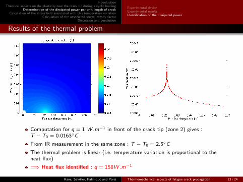
Computation for q = 1 W .m−1 in front of the crack tip (zone 2) gives :T − T0 = 0.0163◦C
From IR measurement in the same zone : T − T0 = 2.5◦C
The thermal problem is linear (i.e. temperature variation is proportional to theheat flux)
=⇒ Heat flux identified : q = 158W .m−1
Ranc, Saintier, Palin-Luc and Paris Thermomechanical aspects of fatigue crack propagation 13 / 24

IntroductionTheorical aspects on the plasticity near the crack tip during a cyclic loading
Determination of the dissipated power per unit length of crackCalculation of the stress field associated with this temperature variation
Calculation of the associated stress intesity factorDiscussion and conclusion
AssumptionsDecomposition of the thermomechanical problem
Calculation of the stress field
Calculation of the stress field
Ranc, Saintier, Palin-Luc and Paris Thermomechanical aspects of fatigue crack propagation 14 / 24

IntroductionTheorical aspects on the plasticity near the crack tip during a cyclic loading
Determination of the dissipated power per unit length of crackCalculation of the stress field associated with this temperature variation
Calculation of the associated stress intesity factorDiscussion and conclusion
AssumptionsDecomposition of the thermomechanical problem
The thermomechanical problem
Assumptions of the thermomechanical problem
The reverse cyclic plastic zone is small and a line heatsource is considered,
Slow moving crack ; static and constant heat source duringthe test,
The stress is calculate using the temperature field obtainedpreviously,
Plane stress conditions,
Outside the RCPZ, the material behavior is suppose to bethermo-elastic : E = 210GPa, ν = 0.29, ρ = 7800 kgm−3
and α = 1.2× 10⁻⁵ K−1,
Because of the alternating plasticity in the RCPZ, themean radial stress tends toward to zero at the interfacewith the RCPZ,
because KI is computed from the stress field outside theRCPZ, only the elastic domain is considered.
Ranc, Saintier, Palin-Luc and Paris Thermomechanical aspects of fatigue crack propagation 15 / 24

IntroductionTheorical aspects on the plasticity near the crack tip during a cyclic loading
Determination of the dissipated power per unit length of crackCalculation of the stress field associated with this temperature variation
Calculation of the associated stress intesity factorDiscussion and conclusion
AssumptionsDecomposition of the thermomechanical problem
Decomposition of the thermomechanical problem
Decomposition in a purely mechanical problem and a purely thermal problem
This decomposition is correct if :
the heating effects are small and do not modify the size of the RCPZ
the compressive stress does not create crack closure
Ranc, Saintier, Palin-Luc and Paris Thermomechanical aspects of fatigue crack propagation 16 / 24

IntroductionTheorical aspects on the plasticity near the crack tip during a cyclic loading
Determination of the dissipated power per unit length of crackCalculation of the stress field associated with this temperature variation
Calculation of the associated stress intesity factorDiscussion and conclusion
AssumptionsDecomposition of the thermomechanical problem
Decomposition of the purely thermal problem
Decomposition of the purely thermal problem in two cases
The case (a) without crack allows to calculate the stress distribution σ(x)
The case (b) with crack allows to calculate the stress intensity factor Ktemp
via the Green functionRanc, Saintier, Palin-Luc and Paris Thermomechanical aspects of fatigue crack propagation 17 / 24
IntroductionTheorical aspects on the plasticity near the crack tip during a cyclic loading
Determination of the dissipated power per unit length of crackCalculation of the stress field associated with this temperature variation
Calculation of the associated stress intesity factorDiscussion and conclusion
AssumptionsDecomposition of the thermomechanical problem
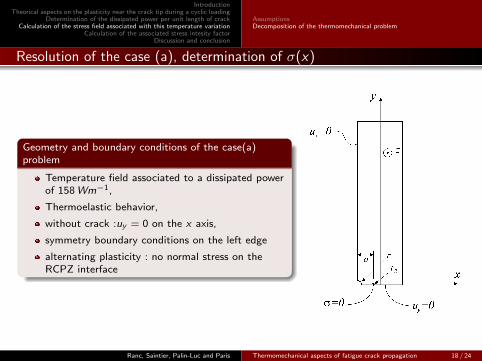
Resolution of the case (a), determination of σ(x)
Geometry and boundary conditions of the case(a)problem
Temperature field associated to a dissipated powerof 158Wm−1,
Thermoelastic behavior,
without crack :uy = 0 on the x axis,
symmetry boundary conditions on the left edge
alternating plasticity : no normal stress on theRCPZ interface
Ranc, Saintier, Palin-Luc and Paris Thermomechanical aspects of fatigue crack propagation 18 / 24

IntroductionTheorical aspects on the plasticity near the crack tip during a cyclic loading
Determination of the dissipated power per unit length of crackCalculation of the stress field associated with this temperature variation
Calculation of the associated stress intesity factorDiscussion and conclusion
AssumptionsDecomposition of the thermomechanical problem
Results : evolution of the normal stress toward y axis
Normal stress toward y axis distributionNormal stress toward y axis along x axis
Negative stress (compression) in a zone close to the crack tip
Ranc, Saintier, Palin-Luc and Paris Thermomechanical aspects of fatigue crack propagation 19 / 24

IntroductionTheorical aspects on the plasticity near the crack tip during a cyclic loading
Determination of the dissipated power per unit length of crackCalculation of the stress field associated with this temperature variation
Calculation of the associated stress intesity factorDiscussion and conclusion
Calculation of the associated stress intesity factor
Calculation of the associated stress intesity factor
Ranc, Saintier, Palin-Luc and Paris Thermomechanical aspects of fatigue crack propagation 20 / 24

IntroductionTheorical aspects on the plasticity near the crack tip during a cyclic loading
Determination of the dissipated power per unit length of crackCalculation of the stress field associated with this temperature variation
Calculation of the associated stress intesity factorDiscussion and conclusion
Calculation of the effect on the stress intensity factor
Calculation of the effect on the stress intensity factor
The effect on the stress intensity factor is calculated withequation :
Ktemp =2√π
∫ a
0σ(x)
√a
√a2 − x2
dx
For a dissipated power of 158Wm−1 (∆K = 20MPa√m and
R = 0.1), Ktemp = −0.3MPa√m
Negative value due to the compressive stress state near thecrack tip
Small thermal effects for these test condition (C40 steel,∆K = 20MPa
√m and a loading frequency of 200Hz)
Ranc, Saintier, Palin-Luc and Paris Thermomechanical aspects of fatigue crack propagation 21 / 24

IntroductionTheorical aspects on the plasticity near the crack tip during a cyclic loading
Determination of the dissipated power per unit length of crackCalculation of the stress field associated with this temperature variation
Calculation of the associated stress intesity factorDiscussion and conclusion
Discussion and conclusion
Discussion and conclusion
Ranc, Saintier, Palin-Luc and Paris Thermomechanical aspects of fatigue crack propagation 22 / 24

IntroductionTheorical aspects on the plasticity near the crack tip during a cyclic loading
Determination of the dissipated power per unit length of crackCalculation of the stress field associated with this temperature variation
Calculation of the associated stress intesity factorDiscussion and conclusion
Discussion and conclusion
Due to the dissipation in heat in the RCPZ there are thermal stresses ahead of the crack tip
They modify the stress intensity factor during a fatigue loading, it has to be corrected by thenegative factor Ktemp :
KI (t) = Kcyc (t) + Ktemp
The temperature has no effect on ∆K but it has an effect on Kmax and Kmin :
Kmax = Kcyc max + Ktemp and Kmin = Kcyc min + Ktemp
The ratio RK =KminKmax
is affected by the temperature correction :
RK =Kcyc min + Ktemp
Kcyc max + Ktemp6=
Kcyc min
Kcyc max
for a stress intensity factor ∆K = 20 MPa√m and a RK = 0.1, the thermal correction gives
RK = 0.11 (10%)
The thermal correction in our experimental conditions remains small,
Is this thermal effect always negligible, and especially in the case of materials with lower yieldstress or for tests carried out with higher frequency ?
Ranc, Saintier, Palin-Luc and Paris Thermomechanical aspects of fatigue crack propagation 23 / 24

IntroductionTheorical aspects on the plasticity near the crack tip during a cyclic loading
Determination of the dissipated power per unit length of crackCalculation of the stress field associated with this temperature variation
Calculation of the associated stress intesity factorDiscussion and conclusion
Thank you for your attention
Ranc, Saintier, Palin-Luc and Paris Thermomechanical aspects of fatigue crack propagation 24 / 24