motorcycle and safety barrier crash testing feasibility study
DESCRIPTION
Motorcycle and Safety Barrier Crash Testing Feasibility StudyTRANSCRIPT
Department of Transport and Regional ServicesAustralian Transport Safety Bureau
Motorcycle and Safety BarrierCrash-Testing: Feasibility Study
Chantel Duncan, Bruce Corben,Niklas Truedsson and Claes Tingvall
Accident Research CentreMonash University
II
AUSTRALIAN TRANSPORT SAFETY BUREAUDOCUMENT RETRIEVAL INFORMATION
Report No. Date Pages ISBN ISSN
CR 201 December 2000 61 0 642 25556 3 0810-770X
Title and Subtitle
Motorcycle and Safety Barrier Crash-Testing: Feasibility Study
Authors
Duncan C, Corben B, Truedsson N and Tingvall C
Performing Organisation
Accident Research CentreMonash UniversityVictoria 3800
Sponsored by / Available from
Australian Transport Safety BureauPO Box 967CIVIC SQUARE ACT 2608 Project Officer: John Goldsworthy
Abstract
Roadside barriers are designed to enhance the safety of the road infrastructure by containingerrant vehicles and reducing the severity of off-path collisions. While conventional barrier systemshave performed well for the occupants of passenger cars, their effects on the safety of other roaduser groups, especially motorcyclists, is not well understood. The main purpose of this feasibilitystudy was to recommend a research method for investigating the interactions between motorcyclesand road safety barriers. A review of the relevant national and international literature wasconducted, revealing a relative lack of published material regarding the nature of motorcyclecollisions both with roadside barriers as well as motorcycle crashes in general. Various featuresof barrier systems were identified in the literature as providing a significant safety risk to fallenmotorcyclists, particularly barrier posts. There have been numerous strategies employed, mostlyin Europe, to better protect motorcyclists from impacts with barriers, including the installation ofadditional W-beams, using impact attenuators to cover exposed barrier posts and substitutingtraditional IPE posts with more forgiving “sigma” posts. In addition, there have been several newbarrier designs and/or modifications that have been developed and tested in Europe withpromising results. Guidelines developed for the conduct of physical crash-tests with motorcycleswere reviewed, and alternative methods, such as computer/mathematical simulations andcomponent testing, were also considered. Based on the information from the literature review andsubsequent consultation with several experts and stakeholders, recommendations for a multi-stageresearch program were made.
Keywords
SAFETY BARRIER, CRASH-TEST, MOTORCYCLE, IMPACT, OCCUPANT PROTECTION
NOTES:
(1) This report is disseminated in the interests of information exchange.(2) The views expressed are those of the author(s) and do not necessarily represent those of the Commonwealth.
Reproduction of this page is authorised
III
Contents
ACKNOWLEDGMENTS....................................................................................................... VI
1. EXECUTIVE SUMMARY ................................................................................................ 1
1.1. LITERATURE REVIEW .................................................................................................... 1
1.1.1. General...................................................................................................................... 11.1.2. The Number, Nature and Severity of Injuries Resulting from Collisions with
Different Barrier Types.............................................................................................. 11.1.3. Barrier Design Features Impacting on Motorcyclist Safety......................................... 21.1.4. Safety Performance of Barrier Types with Respect to Motorcyclists........................... 21.1.5. Review of Different Strategies for Better Protecting Motorcyclists............................. 21.1.6. Crash-Testing ............................................................................................................ 31.1.7. Feasibility of Research Methods for Investigating Interactions between
Motorcycles and Safety Barriers ................................................................................ 31.1.8. The Choice of One or Several Test Set-Ups ............................................................... 41.1.9. The Conduct of Physical Crash-Testing ..................................................................... 41.1.10.Variables to be Measured, Instrumentation & Measurement Procedures .................... 4
1.2. CONSULTATION WITH STAKEHOLDERS .................................................................... 5
1.3. RECOMMENDATIONS FOR A RESEARCH PROGRAM................................................ 5
1.3.1. Research and Development Options........................................................................... 51.3.2. Indicative Costs and Timing ...................................................................................... 61.3.3. Options for Sponsorship ............................................................................................ 7
2. ATSB PROJECT SPECIFICATION................................................................................ 9
2.1. INTRODUCTION............................................................................................................... 9
2.2. KEY ELEMENTS OF ATSB PROJECT SPECIFICATION................................................ 9
2.3. BACKGROUND................................................................................................................. 9
2.4. PROJECT DESCRIPTION.................................................................................................. 9
2.5. OBJECTIVES ................................................................................................................... 10
2.6. METHOD ......................................................................................................................... 10
2.7. REPORT........................................................................................................................... 10
3. MUARC DESCRIPTION OF APPROACH AND METHODS......................................... 11
3.1. CONTEXT........................................................................................................................ 11
3.2. PROJECT APPROACH .................................................................................................... 11
3.2.1. Stage 1: Feasibility study ......................................................................................... 11
3.3. POSSIBLE FUTURE STAGES......................................................................................... 12
3.3.1. Stage 2: Crash-Testing Program.............................................................................. 123.3.2. Stage 3: Development of Barrier Performance......................................................... 123.3.3. Stage 4: Promotion of Research Program Findings.................................................. 12
3.4. STUDY OUTPUTS........................................................................................................... 13
4. LITERATURE REVIEW................................................................................................ 14
4.1. THE NUMBER, NATURE AND SEVERITY OF INJURIES RESULTING FROMCOLLISIONS WITH DIFFERENT BARRIER TYPES..................................................... 14
4.2. BARRIER TYPES CURRENTLY IN USE IN AUSTRALIA............................................ 15

IV
4.2.1. Rigid Barriers .......................................................................................................... 154.2.2. Semi-rigid Barriers .................................................................................................. 154.2.3. Flexible Barriers ...................................................................................................... 164.2.4. End-Treatments (Terminals) .................................................................................... 17
4.3. ROADSIDE BARRIER DESIGN FEATURES AND INJURY MECHANISMS ............... 18
4.4. SAFETY PERFORMANCE OF BARRIERS TYPES WITH RESPECT TOMOTORCYCLISTS.......................................................................................................... 19
4.5. REVIEW OF DIFFERENT STRATEGIES FOR BETTER PROTECTINGMOTORCYCLISTS.......................................................................................................... 194.5.1. Sigma Posts ............................................................................................................. 194.5.2. Additional W Beams................................................................................................ 204.5.3. Impact Attenuators .................................................................................................. 214.5.4. Additional Measures Taken to Reduce Risks to Motorcyclists.................................. 214.5.5. Data From Computer and Mathematical Based Simulation Studies .......................... 26
4.6. CRASH-TESTING............................................................................................................ 27
4.6.1. The Feasibility of Physical Crash-Testing and Possible Alternative orSupplementary Approaches ..................................................................................... 27
4.6.2. Computer Simulation Studies of Motorcycle Impacts............................................... 284.6.3. Sub-system/Component Testing............................................................................... 29
4.7. THE CHOICE OF ONE OR SEVERAL TEST SET-UPS TO DISTINGUISHBETWEEN DIFFERENT DESIGN CONCEPTS .............................................................. 31
4.7.1. Previous Approaches Used for Physical Crash-Testing............................................. 314.7.2. Typical Crash Scenarios .......................................................................................... 324.7.3. Review of Homologation Procedures of Crash Barrier Protectors............................. 32
4.8. THE CONDUCT OF PHYSICAL CRASH-TESTING ...................................................... 33
4.8.1. Crash-Testing Guidelines......................................................................................... 334.8.2. The Choice of a Suitable Human Surrogate for Testing ............................................ 334.8.3. Review of the Physical Measurements that may be Obtained from Crash-Test
Dummies to Assess Injury Severity.......................................................................... 35
4.9. VARIABLES TO BE MEASURED, INSTRUMENTATION & MEASUREMENTPROCEDURES................................................................................................................. 36
4.9.1. Electronic Recorded Variables................................................................................. 364.9.2. Mechanically Recorded Variables............................................................................ 374.9.3. Photographic Targets To Be Digitised...................................................................... 374.9.4. Sensor Specifications............................................................................................... 37
5. CONSULTATION WITH STAKEHOLDERS ................................................................. 38
5.1. QUEENSLAND................................................................................................................ 38
5.2. VICTORIA ....................................................................................................................... 40
5.3. NEW SOUTH WALES ..................................................................................................... 42
6. SUMMARY AND RECOMMENDATIONS..................................................................... 45
6.1. BARRIER DESIGN ISSUES AND RIDER INJURY MECHANISMS.............................. 45
6.1.1. Contain and Redirect the Rider or Allow the Rider to Pass Through? ....................... 456.1.2. Barrier Design and Injury Mechanisms .................................................................... 45
6.2. FEASIBILITY OF DIFFERENT RESEARCH METHODS............................................... 45
6.2.1. Physical Crash-Testing ............................................................................................ 466.2.2. Physical Crash-Tests or Computer Simulation.......................................................... 486.2.3. Component Testing.................................................................................................. 48
6.3. RECOMMENDATIONS FOR A RESEARCH PROGRAM.............................................. 48
V
6.3.1. Research and Development Options......................................................................... 486.3.2. Indicative Costs ....................................................................................................... 516.3.3. Indicative Timing .................................................................................................... 516.3.4. Options for Sponsorship .......................................................................................... 52
7. REFERENCES ............................................................................................................. 53
Figures
FIGURE 1: SCHEMATIC DIAGRAM OF IPE POST..................................................................................................20FIGURE 2: SCHEMATIC DIAGRAM OF SIGMA POST. ............................................................................................20FIGURE 3: DIAGRAM OF THE ‘ECRAN MOTARD” FITTED TO AN EXISTING GUARDRAIL. ........................................22FIGURE 4: SCHEMATIC DRAWING OF “ECRAN MOTARD” FITTED TO AN EXISTING GUARDRAIL. ............................22FIGURE 5: PICTURE OF THE “PLASTI-RAIL” FITTED TO EXISTING BARRIER SYSTEM. ............................................23FIGURE 6: SCHEMATIC DIAGRAM OF THE “PLASTI-RAIL” COMPONENTS.............................................................23FIGURE 7: PICTURE OF THE “MOTORAIL”. .........................................................................................................24FIGURE 8: SCHEMATIC DRAWING OF THE “MOTORAIL”......................................................................................24FIGURE 9: PICTURE OF “MOTOTUB” FITTED TO EXISTING BARRIER SYSTEM. .......................................................25FIGURE 10: SCHEMATIC DRAWING OF “MOTOTUB” FITTED TO EXISTING BARRIER SYSTEM ..................................25FIGURE 11: SCHEMATIC DRAWING OF ALUMINIUM PROFILE COVERING WRSB....................................................26FIGURE 12: SUB-SYSTEM TESTS. .......................................................................................................................31
Tables
TABLE 1: PHYSICAL CRASH-TESTING CONFIGURATIONS PREVIOUSLY USED BY RESEARCHERS...........................32

VI
ACKNOWLEDGMENTS
There are many people who provided assistance with the production of this report and whothe authors would like to thank.
We would like to acknowledge and thank the following Road Authorities for the technicalexpertise they provided during the stakeholder discussions:
§ VicRoads, particularly Warwick Pattinson, Sam Pirotta and Rod Howard;
§ Roads and Traffic Authority, NSW, particularly James Holgate, Ross Dal Nevo, ColinJackson, Steve Williamson and Michael Brauer; and
§ Main Roads Queensland, particularly, Lloyd Davis, Mark Olive and Paul Grice.
In addition, we would like to thank the following individuals for their insight and advice onissues pertinent to the report:
§ Sergeant Peter Jenkins from the NSW Police Service;
§ Paul Wilton and Greg Hirst from the NSW Motorcycle Council;
§ Sergeant Steve Lomas and Senior Constable Colin Chamings from Victoria Police;
§ Michael Czajka representing the Federal Motorcycle Coalition;
§ Derek Wainohu, Laboratory Manager from the RTA CrashLab; and
§ Brian Wood.
Finally, we would like to thank John Goldsworthy who, as manager of this project,provided invaluable technical input and advice as well as feedback on draft reports.

1
1 EXECUTIVE SUMMARY
This report has been prepared for the Australian Transport Safety Bureau (ATSB) by theMonash University Accident Research Centre. It constitutes the first stage of a potentialmulti-stage project and takes the form of a feasibility study of motorcycle and safetybarrier crash-testing.
Road safety barriers are designed to enhance the safety of the road infrastructure bycontaining errant vehicles and reducing the severity of off-path collisions. Experienceindicates that conventional barrier systems used in accordance with specific guidelineshave performed well in protecting the occupants of passenger cars. However, their effectson the safety of motorcyclists, is somewhat problematic. Given the limited availableinformation on motorcycle-barrier interactions, and the lack of established procedures formotorcycle crash-testing, ATSB commissioned a preliminary investigation of relevantissues. This report is the principal output of these preliminary investigations.
The main purpose of this initial work was to recommend a research method forinvestigating the interactions between motorcycles and road safety barriers. Specificobjectives were to:
• identify barrier design issues likely to impact on motorcycle rider safety;
• identify relevant rider injury mechanisms;
• identify and assess the feasibility of research methods for investigating interactionsbetween motorcycles and safety barriers;
• recommend a research program, addressing the overall aims described above.
The study has involved a review of the international literature on relevant topics, analysisof motorcycle crash records, and consultation with technical experts and key stakeholdersin three States.
1.1 LITERATURE REVIEW
1.1.1 General
A search of the relevant literature concerning road user impacts with roadside barriersrevealed that there have been very few specific experiments conducted that examine thesafety performance of crash barriers with regard to motorcyclists. The published literatureindicates that researchers have used both a variety of physical crash-testing methods, aswell as various computer and mathematical simulation techniques to investigatemotorcycle crashes.
1.1.2 The Number, Nature and Severity of Injuries Resulting from Collisions withDifferent Barrier Types
Apart from general figures pertaining to the number of collisions between guardrails andmotorcyclists for certain time periods, there is very little information available in theliterature regarding the nature and severity of injuries resulting from collisions withdifferent barrier types.
2
In terms of the size of the problem in Australia, Victorian crash statistics indicate thatbetween the years of 1991 and 1995, there were 9059 accidents involving motorcyclists inVictoria, 84 of which involved the collision of the rider with a guard fence. AustralianCoroner’s records indicate that 2.4% of total rider fatalities involved collisions with safetybarriers in 1994 and 1996.
With specific reference to the involvement of Wire Rope Safety Barriers (WRSBs) inmotorcyclist casualties in Australia, ATSB (2000) reports that Australian State RoadAuthorities reported no such casualties, however the reporting of crashes with barriers doesnot necessarily accurately distinguish between different barrier types.
1.1.3 Barrier Design Features Impacting on Motorcyclist Safety
A review of the literature identified several barrier design issues which impact uponmotorcycle rider safety. The literature suggests that the most dangerous aspect ofguardrails with respect to motorcyclists is exposed guardrail posts. The guardrail postspresent edges which concentrate the impact forces, resulting in more severe injuries tomotorcyclists. This is a potential problem for any barrier system that has exposed posts.Other barrier features that are inherently dangerous to motorcyclists include:
• The jagged edges of wire mesh fences, or wire mesh topped barrier systemswhich provide numerous lacerating surfaces, accentuating rider injury risk;
• Upper and lower W-beam edges;
• Protruding reflectors;
• Barrier systems that are too low as motorcyclists can be catapulted over barriersystems of insufficient height;
• Discontinuous or jagged barrier surfaces, such as concrete barriers withdecorative designs, which present edges to concentrate the forces of impact.
• Rigid barriers (likely to be involved in front-on collisions) which require animpacting rider to absorb virtually all of the kinetic energy at impact.
1.1.4 Safety Performance of Barrier Types with Respect to Motorcyclists
There has been no comprehensive crash-testing program that has compared the safetyperformance of a number of different barrier types in controlled conditions with respect tomotorcyclists, therefore it is difficult to make meaningful comparisons of barrier typesregarding this issue. In general, however, it appears that barriers with a smooth,continuous surface (located reasonably close, and oriented roughly parallel, to the trafficstream) represent less of a safety hazard to motorcyclists as they better allow the rider toslide along the surface of the barrier without the danger of impacting any sharp edges orcorners that can concentrate the impact force. Also, barriers with high energy absorbingproperties which allow for better energy dissipation would decrease the injury risk forfallen motorcyclists.
1.1.5 Review of Different Strategies for Better Protecting Motorcyclists
The three most prevalent methods of improving the design of safety barriers to betterprotect motorcyclists include: the replacement of traditional IPE-100 posts used in most
3
guardrail systems with the more forgiving Sigma-Posts; covering the existing posts withadditional W-beams on the lower section of the guardrail system; and covering exposedposts with specifically designed impact attenuators (Koch & Schueler, 1987; Sala &Astori, 1998).
More recently, there have been a variety of new devices developed by various companiesglobally that can be added to existing barrier systems to improve their safety performancewith regard to motorcyclists. These include: the “Plastrail” (developed by Solidor); the“Motorail” (developed by Solosar); the “Mototub” (made by Sodirel), and; a metal platewhich covers exposed guardrail posts and has a high degree of flexibility enabling it toabsorb energy on impact (sold by SEC-Envel in France).
In addition, the Baltic Construction Company in Sweden has developed a device thatcovers the upper and lower wire rope systems of standard WRSBs. The device consists ofaluminium profiles that can be fitted to existing systems. The device has been subject tocomputer simulations using a motorcycle, a car and a lorry with favourable indications.
1.1.6 Crash-Testing
Although physical crash-testing has not been used in the past to compare the safetyperformance of the main barrier types for motorcyclists, testing out new devices designedto improve the safety performance of existing barriers for motorcyclists has been carriedout in a number of European countries. However, physical crash-testing is not without itslimitations and other methods such as mathematical models and computer simulations arebeing used increasingly by researchers to overcome the financial costs and problems withrepeatability that exist when conducting physical crash-tests. Although these alternativesare not without their own problems, it appears that as the technology advances in theseareas, these methods are becoming increasingly more viable options and/or supplements tophysical crash-testing.
1.1.7 Feasibility of Research Methods for Investigating Interactions betweenMotorcycles and Safety Barriers
Physical crash-tests are advantageous as they are better able to provide more realistic datafor motorcycle crashes. On the other hand, the two main disadvantages of physicalmotorcycle crash-testing include the difficulty of reproducibility of tests as well as theirrelatively costly and time consuming nature (Nieboer, Wismans, Versmissen, vanSlagmaat, Kurawaki, & Ohara, 1993). An alternative method, computer-aided simulationof crash-testing, makes it possible to conduct a large number of simulations at a relativelylow cost, which is important considering the wide range of crash configurations themotorcycle and rider can be subjected to. Various types of mathematical models andcomputer simulations have been used successfully to investigate motorcyclist impacts withbarriers in the past. However it must be noted that although these alternative methods areuseful in terms of their repeatability and their ability to identify the salient aspects ofinjuries and injury mechanisms in crash-test situations, they are limited in various ways,including the fact that the simplification required in these models excludes a thoroughanalysis of the complexity of the situation.
Component testing or sub-system testing provides yet another alternative or supplementaryapproach to physical crash-testing and/or crash simulation. This method provides a way oftesting specific parameters at a relatively low cost by focussing on specific crashcomponents which are believed to be critical to injury severity outcomes. Component
4
testing has been used successfully in the past for various purposes, including investigationinto pedestrian/car impacts, where it can be used to help break down the complexity of thesituation and identify factors influencing the injury outcome. Therefore, to overcome thecost and difficulty of full-scale motorcycle into barrier crash-testing, sub-system testingmay be considered as an option for investigating these impacts.
1.1.8 The Choice of One or Several Test Set-Ups
There have been several different approaches taken by researchers in the past for thepurposes of physical crash-testing. Variations between tests include the impact speed,impact angle, whether the impact occurs with the rider still on the motorcycle or with therider having already separated from the motorcycle, and if so, with the rider head or feetfirst. The actual crash configuration adopted will depend on whether to investigate typicalcrash-test scenarios and/or worst/extreme case scenarios.
1.1.9 The Conduct of Physical Crash-Testing
In the event that a physical crash-testing program is undertaken either in isolation or inconjunction with alternative methods, there are certain guidelines developed for suchpurposes. Guidelines developed by a group of motorcyclist safety experts, appointed bythe International Organisation for Standardisation (ISO), cover virtually all aspects of theconduct of physical crash-testing, including: suitable crash-test dummies, physicalmeasurements to be taken, injury assessment variables, instrumentation and measurementspecifications.
1.1.10 Variables to be Measured, Instrumentation & Measurement Procedures
A specialised crash-test dummy for motorcycle crash-testing has been developed and isspecified in ISO 13232. The basis dummy recommended by the ISO for motorcycle crash-testing is a Hybrid III 50th percentile male dummy with sit/stand construction, standardnon-sliding knees and head/neck assembly compatible with either a 3 or 6 axis upper neckload cell. However, as the Hybrid III dummy was developed for purposes other thanmotorcycle crash-testing eg, simulating restrained car occupants in frontal impacts, it haslimited means to assess some of the main factors in motorcycle crashes due to thebiofidelity characteristics being specialised for their original intended function. To turn theHybrid III dummy into a ISO 13232 motorcyclist dummy, thereby making it useful inmotorcycle crash-testing, certain modifications are required. Among the more importantfeatures of a motorcyclist dummy (compared to a vehicle occupant dummy) are the abilityfor the hands of the dummy to grip the motorcycle handlebars, the ability of the head of thedummy to retain a helmet, improved biofidelity of neck movements and severalmodifications to the biofidelity of the lower limb, including the use of frangible upper andlower leg bones, which aid in the collection of injury data specifically relevant tomotorcycle crashes.
There are a number of injury assessment variables that are specified in ISO 13232, as wellas guidelines regarding the instrumentation to be used, the variables that should bemeasured and the measurement procedures that should be followed in collecting the data.In addition, further recommendations and guidelines are provided for full-scale crash-testing and specifications regarding appropriate sensors to be used for compatiblity withthe Hybrid III basis dummy (if this is to be used) are included.
5
1.2 CONSULTATION WITH STAKEHOLDERS
Consultation with Main Roads Queensland was conducted on Monday 10 July 2000, andprovided both policy and operational perspectives from the Main Roads staff involved.Officers from VicRoads, the Victorian Motorcycle Police and the Federal MotorcycleCoalition were consulted in Victoria on Tuesday 29 August, 2000. Also, three separateconsultations were held on Thursday 7 September, 2000 with stakeholders and experts inNSW including officers from the Roads and Traffic Authority and NSW Police Service,and representatives from the NSW Motorcycle Council. The main issues arising from thediscussions, as they relate to the current project, are summarised in this report.
1.3 RECOMMENDATIONS FOR A RESEARCH PROGRAM
1.3.1 Research and Development Options
There are three main options for conducting research and development of safetyenhancements for motorcyclists impacting roadside barriers, namely: full-scale crash-testing; crash simulation modelling; and, component testing. Any of these options, orcombinations of them, could be selected to help in the development of safer barrierdesigns.
In light of the relative advantages and limitations, including costs, of each of these options,it is recommended that the following program of research be considered:
i) Undertake Motorcyclist Crash Study - Undertake an in-depth study of (selectedtypes of) motorcyclist crashes across Australia, using crash reconstruction methods,to further our understanding of the number, nature and severity of run-off-the-roadmotorcyclist crashes, including crashes involving impacts with roadside barriers.
ii) Barrier Design Criteria and Guidelines – Establish the design features or criteria towhich the designers of roadside barriers should aspire.
iii) Develop New Barrier Designs – Based on stages (i) and (ii) above, and inpartnership with the barrier manufacturing industry, develop new barrier designs ormodifications/additions to existing barriers for component testing and assessment. Inaddition to the development of new barrier designs and/or modifications, it would benecessary to test these barriers/modifications for compliance with existing standards.Consideration of the likely benefit-cost ratio for implementing new barrier designscould also be undertaken at this stage.
iv) Undertake Component Testing – New barrier designs would be evaluated usingcomponent testing to assess the human tolerance of a number of individual body partsto impact with various barrier design components. The important body parts andbarrier components to be tested would be determined from the results of stages (i)and (ii), as well as from a knowledge of human biomechanics and injurymechanisms.
An important feature of component testing is that it enables an understanding to begained, from first principles, of the interaction between individual human and barriercomponents, before introducing real-world complexity to a testing program. Newknowledge or more sophisticated crash scenarios can then be built.
6
v) Undertake Crash Simulation Modelling – Data and knowledge gained from stage(iv) (and earlier stages) would provide input on physical measures of impactsbetween human body parts and barriers, for use in calibrating and developing crashsimulation models.
It is also recommended that throughout any development and testing program, motorcycleriders and other road user groups and stakeholders be involved to ensure that theirperspectives are adequately understood and considered in the research program.
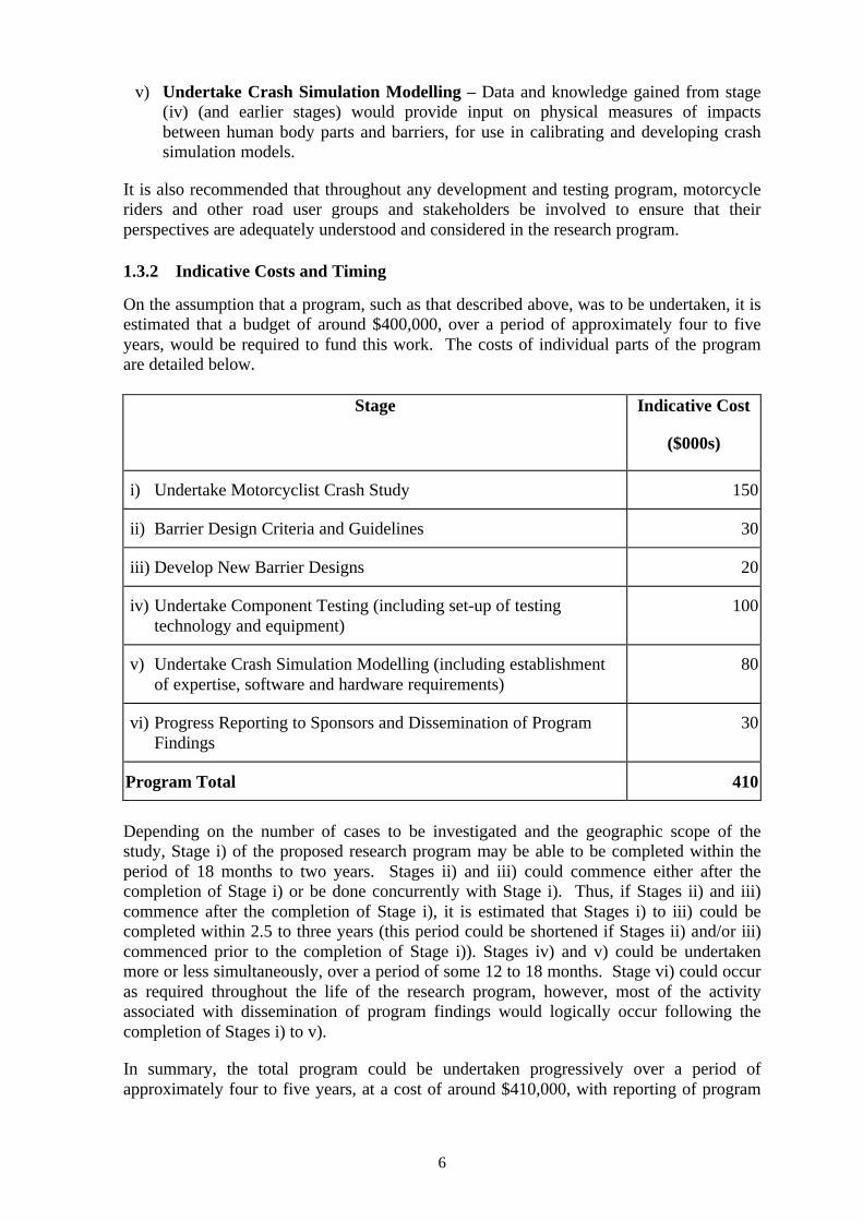
1.3.2 Indicative Costs and Timing
On the assumption that a program, such as that described above, was to be undertaken, it isestimated that a budget of around $400,000, over a period of approximately four to fiveyears, would be required to fund this work. The costs of individual parts of the programare detailed below.
Stage Indicative Cost
($000s)
i) Undertake Motorcyclist Crash Study 150
ii) Barrier Design Criteria and Guidelines 30
iii) Develop New Barrier Designs 20
iv) Undertake Component Testing (including set-up of testing technology and equipment)
100
v) Undertake Crash Simulation Modelling (including establishmentof expertise, software and hardware requirements)
80
vi) Progress Reporting to Sponsors and Dissemination of Program Findings
30
Program Total 410
Depending on the number of cases to be investigated and the geographic scope of thestudy, Stage i) of the proposed research program may be able to be completed within theperiod of 18 months to two years. Stages ii) and iii) could commence either after thecompletion of Stage i) or be done concurrently with Stage i). Thus, if Stages ii) and iii)commence after the completion of Stage i), it is estimated that Stages i) to iii) could becompleted within 2.5 to three years (this period could be shortened if Stages ii) and/or iii)commenced prior to the completion of Stage i)). Stages iv) and v) could be undertakenmore or less simultaneously, over a period of some 12 to 18 months. Stage vi) could occuras required throughout the life of the research program, however, most of the activityassociated with dissemination of program findings would logically occur following thecompletion of Stages i) to v).
In summary, the total program could be undertaken progressively over a period ofapproximately four to five years, at a cost of around $410,000, with reporting of program
7
findings occurring at appropriate intervals both during and after this four to five yearperiod. The estimates of costs and timing should be regarded as indicative only, andshould be subject to detailed development if further consideration of this research programis proposed.
1.3.3 Options for Sponsorship
It would be desirable to seek funding from a number of Australian jurisdictions to enablethis program to be undertaken. The issue of motorcyclist impacts with roadside barriers isone of national significance, which should help in establishing a cooperative researchprogram into which a number of jurisdictions would contribute funding and all wouldreceive the full benefit of new knowledge gained in the area. Given that this problem isalso one of international concern, the possibilities of seeking funding contributions fromoverseas agencies, especially European countries where motorcycling is very popular,might also be considered if insufficient funds were available nationally.

8
9
2 ATSB PROJECT SPECIFICATION
2.1 INTRODUCTION
This report has been prepared for the Australian Transport Safety Bureau (ATSB) by theMonash University Accident Research Centre (MUARC). It constitutes the first stage of apotential four stage project and takes the form of a feasibility study of motorcycle andsafety barrier crash-testing.
2.2 KEY ELEMENTS OF ATSB PROJECT SPECIFICATION
In its project specification, the ATSB provided background to the safety issues associatedwith motorcyclists colliding with roadside barriers. It also set out the key elements of theproject specification, which for completeness and convenience, are presented below.
2.3 BACKGROUND
Road safety barriers are designed to enhance the safety of the road infrastructure bycontaining errant vehicles and reducing the severity of off-path collisions. Experienceindicates that conventional barrier systems used in accordance with specific guidelineshave performed quite well in protecting the occupants of passenger cars. However, theireffects on the safety of other road user groups, especially motorcyclists, is somewhatproblematic.
Motorcycle organisations have argued that the installation of barriers can expose riders toincreased risk of injury. They have expressed particular concerns about barriers which donot present a smooth face to traffic, such as wire rope safety barriers and W-beam systemswith unprotected support posts. There is presently insufficient evidence to permit anobjective assessment of these concerns.
The Australian Transport Safety Bureau is one of several organisations currentlysponsoring a crash-test program to investigate the interactions between passenger cars,their passive safety systems and road safety barriers. This work is being conducted by theMonash University Accident Research Centre, and is expected to provide insight intodesign issues for manufacturers of both vehicles and barriers.
In the planning stages of this program, consideration was given to including motorcycles inthe test schedule. However, it became obvious that a number of complex issues needed tobe resolved before a suitable motorcycle crash-test method could be implemented.Consequently, the project sponsors agreed to deal with motorcycle testing as a separateinvestigation.
Given the limited available information on motorcycle-barrier interactions, and the lack ofestablished procedures for motorcycle crash-testing, ATSB has decided to commission apreliminary investigation of relevant issues.
2.4 PROJECT DESCRIPTION
This project is envisaged as the first stage of a research program whose overall aims are to:assess and compare the safety performance of major approved barrier types (including wirerope systems); identify barrier design issues which impact on safety performance; and
10
examine the scope for modifying barrier designs to better address the safety needs ofmotorcyclists.
2.5 OBJECTIVES
The main purpose of this initial work is to recommend a research method for investigatingthe interactions between motorcycles and road safety barriers. Specific objectives are to:
• identify barrier design issues likely to impact on motorcycle rider safety;
• identify relevant rider injury mechanisms;
• identify and assess the feasibility of research methods for investigating interactionsbetween motorcycles and safety barriers;
this is expected to focus on the feasibility of physical crash-testing, but mayalso consider alternative (or supplementary) approaches, such as computermodelling techniques; and
• recommend a research program, addressing the overall aims described above;
this should include timing and cost details, and optional approaches ifappropriate.
2.6 METHOD
It has been anticipated that this study will involve:
• a review of the international literature on relevant topics;
• analysis of motorcycle crash records;
• consultation with technical experts and key stakeholders as required.
2.7 REPORT
A report is to be provided at the end of the study in a form suitable for publishing in theATSB ‘CR’ series. This report shall include:
• a succinct executive summary;
• a review of the relevant literature;
• a description of findings in relation to specified objectives; and
• conclusions and recommendations, including details of the proposed research program.
11
3 MUARC DESCRIPTION OF APPROACH AND METHODS
3.1 CONTEXT
Wire rope barriers, and similar types of flexible barriers with posts, are being usedincreasingly in Australia and elsewhere in the world to prevent death or serious injuries toroad users whose vehicles leave the roadway. The performance characteristics of the newgeneration of barriers, in both real-world crashes and crash-testing situations, appear verypromising for cars and for light trucks. However, motorcyclists have expressed concernthat their safety may be compromised by the use of wire rope barriers and similar designswith exposed posts. At present, there is a lack of scientific knowledge from which toassess such concerns, and on how to improve barrier design for motorcyclists.
Major aims of proposed research in this field are to assess and compare the safetyperformance of major approved barrier types (including wire rope systems) when struck bya motorcyclist, and to develop possible modifications to these barrier systems to improvetheir safety performance and minimise any specific risks to motorcyclists.
3.2 PROJECT APPROACH
While this proposal describes four key stages required to achieve this overall aim, itprimarily addresses the first stage of the research program. It has been decided thatinitially, funding be provided for Stage 1 only, to enable an assessment of feasibility andthe development of test methods to be carried out before deciding on whether to undertakesubsequent stages of an overall program of research. If the findings of Stage 1 indicatethat the proposed research program is both feasible and capable of providing valuable newknowledge, Stage 1 will also define and cost the further stages required to achieve theoverall research aims described earlier.
Thus, while the primary focus of this section is to address the requirements of thefeasibility study, a preliminary description of possible future stages (i.e., Stages 2, 3 and 4)has been included in this proposal.
3.2.1 Stage 1: Feasibility study
Stage 1, the feasibility study, will involve a review of the international and nationalliterature on the crashworthiness of barrier systems, with a particular focus on the injurymechanisms and their severity outcomes for motorcyclists. An important aspect of theinvestigation of injury mechanisms and their severity outcomes will be the identification ofdesign features of currently approved barrier types that cause injury and/or influence injuryseverity.
Motorcyclist crash-testing methods will also be identified from the published literature andtheir feasibility in achieving the objectives of this research proposal assessed. Of particularinterest will be:
Ø consideration of the two basic philosophies for barrier design, namely, to retain (andredirect) an impacting motorcyclist on the road or to allow the motorcyclist to passthrough the barrier;
Ø the choice of one or several test set-ups to distinguish between different designconcepts;
12
Ø the physical measurements that may be obtained from crash-test dummies to assessinjury severity outcomes;
Ø the choice of a suitable human surrogate for the tests.
Consultation with technical experts and key stakeholders will be undertaken mainlyfollowing the completion of the literature review. It is proposed that a specific aspect ofthe consultation process will involve discussions with motorcyclists to ensure that theirviews are adequately captured during the feasibility study.
As required by the project specification, consideration will be given to alternative, orsupplementary, approaches to comparing and assessing the safety performance of variousbarrier systems when struck by motorcyclists. Such alternative approaches might includecrash simulation using computer-modelling techniques.
In the absence of relevant published information on real-world crash experience, Victorian(and if necessary, other jurisdictions) crash records may be searched and analysed toprovide an indication of the number, nature and severity of injuries resulting fromcollisions with roadside barriers. One option would be to examine in greater detail,motorcyclist crashes investigated as part of the Victorian “Fatal single vehicle crash study”carried out by Haworth et al. (1997), though sample sizes may limit the usefulness of thisapproach. A decision on whether to carry out these crash analyses will be made followingan initial review of the published literature.
Subject to a satisfactory assessment of the feasibility of the proposed testing anddevelopment stages of the project, a crash-testing program for subsequent stages will bedefined. Definition of the overall program will include recommended test methods, studyoutputs, time schedule, costing for each stage and funding options for conducting theprogram of research.
3.3 POSSIBLE FUTURE STAGES
3.3.1 Stage 2: Crash-Testing Program
Stage 2 could involve the development of crash-testing technology, with the possibility ofimplementing such technology in a series of barrier crash-tests.
3.3.2 Stage 3: Development of Barrier Performance
In collaboration with barrier manufacturers, barrier designs could be developed inaccordance with the research findings of Stage 2 and modified designs produced. Barriercrash-testing could then be undertaken to compare the safety performance of modifiedbarriers with the original designs tested in Stage 2.
3.3.3 Stage 4: Promotion of Research Program Findings
Though presented as an optional stage in the overall project, it is recommended that twoimportant further steps be undertaken. The first involves integrating all recommendationsfrom Stage 3 and defining an improved approach to erecting and modifying barrier systemsto enhance safety for all road users, including motorcyclists. The second important steprelates to the transfer of knowledge so that relevant agencies, industries, community groupsand individuals in society are made aware of the key findings from the study.
13
3.4 STUDY OUTPUTS
The main output of Stage 1 – the feasibility study – will be a report on the literature searchand review, as they relate to the specific objectives of the feasibility study. That is, thereport will be structured such that it:
Ø identifies barrier design issues likely to impact on motorcycle rider safety;
Ø identifies relevant rider injury mechanisms;
Ø identifies and assesses the feasibility of research methods for investigating interactionsbetween motorcycles and safety barriers, including possible alternative approaches; and
Ø recommends a research program, which addresses the overall aims described above, aswell as including timing and cost details, and optional approaches if appropriate.
Given the relatively high costs of conducting full-scale crash-testing programs, particularlywhere special expertise is involved, or must be developed, careful consideration will begiven in the feasibility study report to costs for any testing and development research thatmight be recommended.
14
4 LITERATURE REVIEW
This chapter discusses the main findings of the literature review, as it relates to theobjectives of the feasibility study. It covers, under separate headings, the key researchquestions defined in the project brief and in MUARC’s proposal.
4.1 THE NUMBER, NATURE AND SEVERITY OF INJURIES RESULTINGFROM COLLISIONS WITH DIFFERENT BARRIER TYPES.
There are limited data available relating to motorcyclist impacts with guardrails onAustralian Roads. Gowan (1996) reported that in Victoria between the years of 1991 and1995, there were 9059 accidents involving motorcyclists, 84 of which involved thecollision of the rider with a guard fence. However, no other details were given regardingthe type of guardrails involved. Also, Haworth, Smith, Brumen and Pronk (1997) foundthat out of 222 motorcyclist casualties in metropolitan Melbourne, eight involved sometype of barrier.
A report produced by ATSB (2000) summarised the additional relevant availableinformation regarding motorcycle collisions with barriers, namely:
• The involvement of any type of barrier in motorcyclist casualties is consistentlyfound to be less than 5% in accident studies;
• In South Australia, 2.6% of all fatal motorcycle crashes between 1985 and 1991involved initial collision with a guardrail;
• Australian Coroner’s records indicate that 2.4% of total rider fatalities involvedcollisions with safety barriers in 1994 and 1996.
With specific reference to the involvement of Wire Rope Safety Barriers in motorcyclistcasualties in Australia, ATSB (2000) reports that Australian State Road Authoritiesreported no such casualties, however the reporting of crashes with barriers does notnecessarily distinguish between different barrier types.
Globally, there have been varying estimates made regarding the frequency of motorcyclistimpacts with guardrails. In California, it was reported by Ouellet (1982) that out of 900motorcycle accidents, collisions with barriers accounted for 63 somatic region injuries and35 head-neck region injuries, totalling 98 injuries overall. In terms of the severity ofinjuries sustained by riders who impacted guardrails, the author reported that for 30.2% ofsuch incidents, the maximum abbreviated injury scale (MAIS) was ≥ 3. In addition, it wasreported that of the 900 cases examined in the study, “….every rider who struck either aW-beam barrier or metal mesh fencing suffered at least multiple extremity fractures; sixwere killed, three by partial or total decapitation.” (Ouellet, 1982, page 124).
In West Germany, 15% of all motorcycle rider or pillion deaths result from collisionaccidents with guardrail posts (Koch & Schueler, 1987) and 66% of motorcyclists suffervery severe trauma after impacting with guardrails.
Quincey, Vulin and Mounier (1988) reported that in a rural area of France on 940km ofhighway with 100% of its length with median barrier and 40% of its length with roadsideguardrail, it was found that 9.5% of all motorcycle accidents involved an impact with aguardrail between the years of 1980 and 1982. In approximately 70km of road studied in
15
an urban area of France with 100% of its length fitted with median barrier and 62% of itslength fitted with roadside guardrail, it was found that 28% of motorcycle accidentsinvolved barrier impact, accounting for two-thirds of the corresponding fatalities over atwo year period (1978-1979).
4.2 BARRIER TYPES CURRENTLY IN USE IN AUSTRALIA
There are three main types of barrier used on Australian roads: rigid barriers, semi-rigidbarriers and flexible barriers. Rigid concrete barriers, semi-rigid steel “W” shape beambarriers and flexible wire rope barriers (tensioned cables with frangible posts) have beensatisfactorily crash tested and comply with Australian Standard AS/NZ 3845:1999 orrecognised international standards (VicRoads, personal communication). These barriertypes (discussed in the following sections) differ in terms of their deflection and energyabsorption properties and their suitability for different road characteristics.
Once it has been established by road authorities that installation of a barrier is, in fact,warranted for a particular location, there are several factors that need to be considered inchoosing an appropriate barrier system. Installation cost, maintenance cost, rigidity(containment performance, deflection), site conditions, particularly ground slope, distancefrom the travelled roadway, feasibility of providing impact absorbing end-treatments and,in some situations aesthetics, are all taken into account when making a choice of onebarrier type over another. In many cases, however, there may be a choice between barriertypes (or a wide median) subject to individual detailed design possibilities (VicRoads,personal communication).
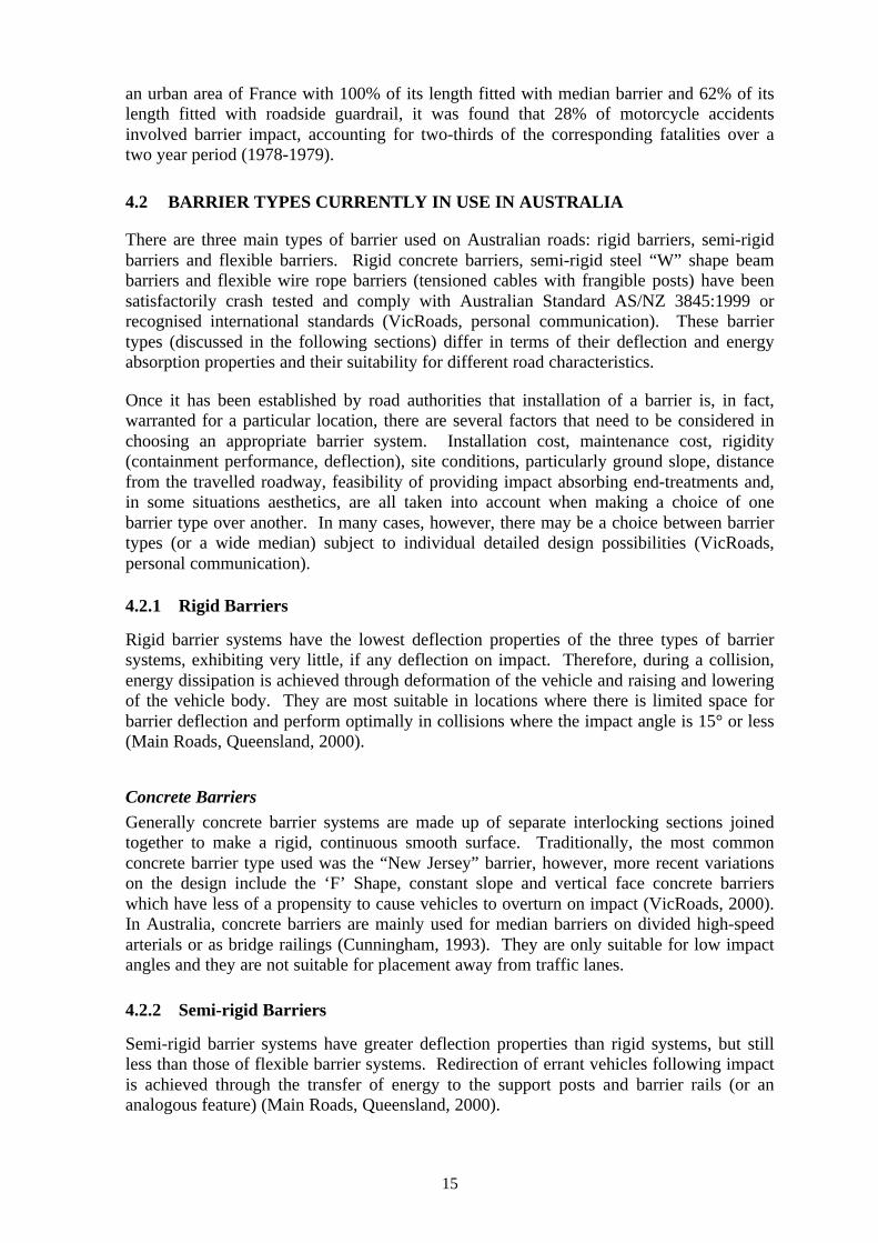
4.2.1 Rigid Barriers
Rigid barrier systems have the lowest deflection properties of the three types of barriersystems, exhibiting very little, if any deflection on impact. Therefore, during a collision,energy dissipation is achieved through deformation of the vehicle and raising and loweringof the vehicle body. They are most suitable in locations where there is limited space forbarrier deflection and perform optimally in collisions where the impact angle is 15° or less(Main Roads, Queensland, 2000).
Concrete BarriersGenerally concrete barrier systems are made up of separate interlocking sections joinedtogether to make a rigid, continuous smooth surface. Traditionally, the most commonconcrete barrier type used was the “New Jersey” barrier, however, more recent variationson the design include the ‘F’ Shape, constant slope and vertical face concrete barrierswhich have less of a propensity to cause vehicles to overturn on impact (VicRoads, 2000).In Australia, concrete barriers are mainly used for median barriers on divided high-speedarterials or as bridge railings (Cunningham, 1993). They are only suitable for low impactangles and they are not suitable for placement away from traffic lanes.
4.2.2 Semi-rigid Barriers
Semi-rigid barrier systems have greater deflection properties than rigid systems, but stillless than those of flexible barrier systems. Redirection of errant vehicles following impactis achieved through the transfer of energy to the support posts and barrier rails (or ananalogous feature) (Main Roads, Queensland, 2000).
16
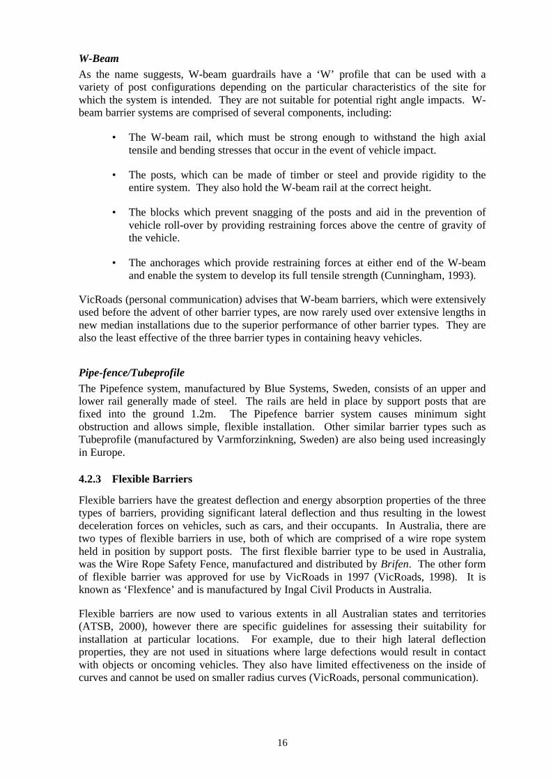
W-BeamAs the name suggests, W-beam guardrails have a ‘W’ profile that can be used with avariety of post configurations depending on the particular characteristics of the site forwhich the system is intended. They are not suitable for potential right angle impacts. W-beam barrier systems are comprised of several components, including:
• The W-beam rail, which must be strong enough to withstand the high axialtensile and bending stresses that occur in the event of vehicle impact.
• The posts, which can be made of timber or steel and provide rigidity to theentire system. They also hold the W-beam rail at the correct height.
• The blocks which prevent snagging of the posts and aid in the prevention ofvehicle roll-over by providing restraining forces above the centre of gravity ofthe vehicle.
• The anchorages which provide restraining forces at either end of the W-beamand enable the system to develop its full tensile strength (Cunningham, 1993).
VicRoads (personal communication) advises that W-beam barriers, which were extensivelyused before the advent of other barrier types, are now rarely used over extensive lengths innew median installations due to the superior performance of other barrier types. They arealso the least effective of the three barrier types in containing heavy vehicles.
Pipe-fence/TubeprofileThe Pipefence system, manufactured by Blue Systems, Sweden, consists of an upper andlower rail generally made of steel. The rails are held in place by support posts that arefixed into the ground 1.2m. The Pipefence barrier system causes minimum sightobstruction and allows simple, flexible installation. Other similar barrier types such asTubeprofile (manufactured by Varmforzinkning, Sweden) are also being used increasinglyin Europe.
4.2.3 Flexible Barriers
Flexible barriers have the greatest deflection and energy absorption properties of the threetypes of barriers, providing significant lateral deflection and thus resulting in the lowestdeceleration forces on vehicles, such as cars, and their occupants. In Australia, there aretwo types of flexible barriers in use, both of which are comprised of a wire rope systemheld in position by support posts. The first flexible barrier type to be used in Australia,was the Wire Rope Safety Fence, manufactured and distributed by Brifen. The other formof flexible barrier was approved for use by VicRoads in 1997 (VicRoads, 1998). It isknown as ‘Flexfence’ and is manufactured by Ingal Civil Products in Australia.
Flexible barriers are now used to various extents in all Australian states and territories(ATSB, 2000), however there are specific guidelines for assessing their suitability forinstallation at particular locations. For example, due to their high lateral deflectionproperties, they are not used in situations where large defections would result in contactwith objects or oncoming vehicles. They also have limited effectiveness on the inside ofcurves and cannot be used on smaller radius curves (VicRoads, personal communication).
17
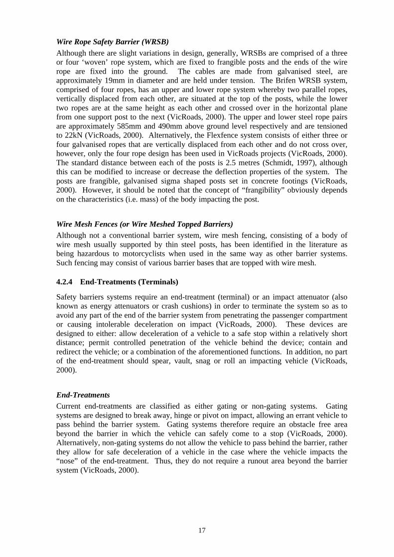
Wire Rope Safety Barrier (WRSB)Although there are slight variations in design, generally, WRSBs are comprised of a threeor four ‘woven’ rope system, which are fixed to frangible posts and the ends of the wirerope are fixed into the ground. The cables are made from galvanised steel, areapproximately 19mm in diameter and are held under tension. The Brifen WRSB system,comprised of four ropes, has an upper and lower rope system whereby two parallel ropes,vertically displaced from each other, are situated at the top of the posts, while the lowertwo ropes are at the same height as each other and crossed over in the horizontal planefrom one support post to the next (VicRoads, 2000). The upper and lower steel rope pairsare approximately 585mm and 490mm above ground level respectively and are tensionedto 22kN (VicRoads, 2000). Alternatively, the Flexfence system consists of either three orfour galvanised ropes that are vertically displaced from each other and do not cross over,however, only the four rope design has been used in VicRoads projects (VicRoads, 2000).The standard distance between each of the posts is 2.5 metres (Schmidt, 1997), althoughthis can be modified to increase or decrease the deflection properties of the system. Theposts are frangible, galvanised sigma shaped posts set in concrete footings (VicRoads,2000). However, it should be noted that the concept of “frangibility” obviously dependson the characteristics (i.e. mass) of the body impacting the post.
Wire Mesh Fences (or Wire Meshed Topped Barriers)Although not a conventional barrier system, wire mesh fencing, consisting of a body ofwire mesh usually supported by thin steel posts, has been identified in the literature asbeing hazardous to motorcyclists when used in the same way as other barrier systems.Such fencing may consist of various barrier bases that are topped with wire mesh.
4.2.4 End-Treatments (Terminals)
Safety barriers systems require an end-treatment (terminal) or an impact attenuator (alsoknown as energy attenuators or crash cushions) in order to terminate the system so as toavoid any part of the end of the barrier system from penetrating the passenger compartmentor causing intolerable deceleration on impact (VicRoads, 2000). These devices aredesigned to either: allow deceleration of a vehicle to a safe stop within a relatively shortdistance; permit controlled penetration of the vehicle behind the device; contain andredirect the vehicle; or a combination of the aforementioned functions. In addition, no partof the end-treatment should spear, vault, snag or roll an impacting vehicle (VicRoads,2000).
End-TreatmentsCurrent end-treatments are classified as either gating or non-gating systems. Gatingsystems are designed to break away, hinge or pivot on impact, allowing an errant vehicle topass behind the barrier system. Gating systems therefore require an obstacle free areabeyond the barrier in which the vehicle can safely come to a stop (VicRoads, 2000).Alternatively, non-gating systems do not allow the vehicle to pass behind the barrier, ratherthey allow for safe deceleration of a vehicle in the case where the vehicle impacts the“nose” of the end-treatment. Thus, they do not require a runout area beyond the barriersystem (VicRoads, 2000).
18
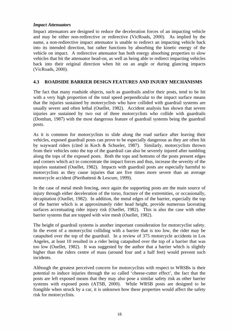
Impact AttenuatorsImpact attenuators are designed to reduce the deceleration forces of an impacting vehicleand may be either non-redirective or redirective (VicRoads, 2000). As implied by thename, a non-redirective impact attenuator is unable to redirect an impacting vehicle backinto its intended direction, but rather functions by absorbing the kinetic energy of thevehicle on impact. A redirective attenuator has both energy absorbing properties to slowvehicles that hit the attenuator head-on, as well as being able to redirect impacting vehiclesback into their original direction when hit on an angle or during glancing impacts(VicRoads, 2000).
4.3 ROADSIDE BARRIER DESIGN FEATURES AND INJURY MECHANISMS
The fact that many roadside objects, such as guardrails and/or their posts, tend to be hitwith a very high proportion of the total speed perpendicular to the impact surface meansthat the injuries sustained by motorcyclists who have collided with guardrail systems areusually severe and often lethal (Ouellet, 1982). Accident analysis has shown that severeinjuries are sustained by two out of three motorcyclists who collide with guardrails(Domhan, 1987) with the most dangerous feature of guardrail systems being the guardrailposts.
As it is common for motorcyclists to slide along the road surface after leaving theirvehicles, exposed guardrail posts can prove to be especially dangerous as they are often hitby wayward riders (cited in Koch & Schueler, 1987). Similarly, motorcyclists thrownfrom their vehicles onto the top of the guardrail can also be severely injured after tumblingalong the tops of the exposed posts. Both the tops and bottoms of the posts present edgesand corners which act to concentrate the impact forces and thus, increase the severity of theinjuries sustained (Ouellet, 1982). Impacts with guardrail posts are especially harmful tomotorcyclists as they cause injuries that are five times more severe than an averagemotorcycle accident (Pieribattesti & Lescure, 1999).
In the case of metal mesh fencing, once again the supporting posts are the main source ofinjury through either deceleration of the torso, fracture of the extremities, or occasionally,decapitation (Ouellet, 1982). In addition, the metal edges of the barrier, especially the topof the barrier which is at approximately rider head height, provide numerous laceratingsurfaces accentuating rider injury risk (Ouellet, 1982). This is also the case with otherbarrier systems that are topped with wire mesh (Ouellet, 1982).
The height of guardrail systems is another important consideration for motorcyclist safety.In the event of a motorcyclist colliding with a barrier that is too low, the rider may becatapulted over the top of the guardrail. In a review of 375 motorcycle accidents in LosAngeles, at least 10 resulted in a rider being catapulted over the top of a barrier that wastoo low (Ouellet, 1982). It was suggested by the author that a barrier which is slightlyhigher than the riders centre of mass (around four and a half feet) would prevent suchincidents.
Although the greatest perceived concern for motorcyclists with respect to WRSBs is theirpotential to induce injuries through the so called ‘cheese-cutter effect’, the fact that theposts are left exposed means that they may also pose a similar safety risk as other barriersystems with exposed posts (ATSB, 2000). While WRSB posts are designed to befrangible when struck by a car, it is unknown how these properties would affect the safetyrisk for motorcyclists.
19
4.4 SAFETY PERFORMANCE OF BARRIERS TYPES WITH RESPECT TOMOTORCYCLISTS.
In the International testing standards for the evaluation of safety barriers, motorcyclistshave not been explicitly considered as test vehicles (Gowan, 1996). This has been justifiedbased on the following three arguments:
1. That the concept of redirecting the vehicle, namely the motorcycle, has littlemeaning in safety terms;
2. That any collision of the rider with any given rigid object will result in great traumafor the motorcyclist;
3. That the probability of crashes of motorcyclists into safety barriers is low.
Given this stance on crash-tests between motorcyclists and safety barriers, there is verylimited existing information relating to the safety performance of different barrier typeswith respect to motorcyclists. However, in a general sense, whether or not a barrier systemhas a continuous surface could be expected to have a large impact on the safetyperformance where motorcyclists are concerned. For example, although the rigidity ofconcrete barriers is inherently hazardous in terms of not absorbing the force of impact, formotorcyclists, their continuous surface is preferable to the non-continuous surfaces of W-beam and wire rope systems at low impact angles. This is due to the fact that barriers witha continuous surface enable sliding and “soft” redirection of the victim and allow forgreater distribution of contact forces over a large body area (Sala and Astori, 1998).Alternatively, direct victim–post interaction in the case of non-continuous barriers resultsin concentrated loads acting on the body, generating high flexion/extension movements ofthe body, high decelerations and high inertial loads (Sala and Astori, 1998). However,sharp decorative edges on concrete barriers (such as sound fence), which transform thesurface into a non-continuous barrier, are not desirable in terms of motorcycle safety(Ouellet, 1982). In terms of energy absorbing properties of barrier systems, those whichhave the capacity to dissipate impact energy through deformation or alternate mechanismspresent less of an injury risk to motorcyclists (Sala & Astori, 1998).
4.5 REVIEW OF DIFFERENT STRATEGIES FOR BETTER PROTECTINGMOTORCYCLISTS.
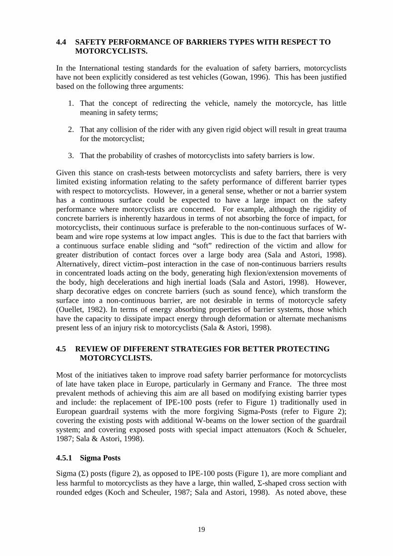
Most of the initiatives taken to improve road safety barrier performance for motorcyclistsof late have taken place in Europe, particularly in Germany and France. The three mostprevalent methods of achieving this aim are all based on modifying existing barrier typesand include: the replacement of IPE-100 posts (refer to Figure 1) traditionally used inEuropean guardrail systems with the more forgiving Sigma-Posts (refer to Figure 2);covering the existing posts with additional W-beams on the lower section of the guardrailsystem; and covering exposed posts with special impact attenuators (Koch & Schueler,1987; Sala & Astori, 1998).
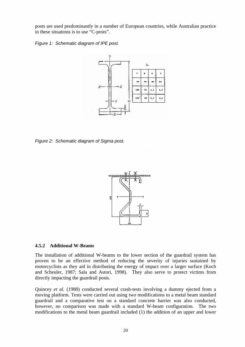
4.5.1 Sigma Posts
Sigma (Σ) posts (figure 2), as opposed to IPE-100 posts (Figure 1), are more compliant andless harmful to motorcyclists as they have a large, thin walled, Σ-shaped cross section withrounded edges (Koch and Scheuler, 1987; Sala and Astori, 1998). As noted above, these
20
posts are used predominantly in a number of European countries, while Australian practicein these situations is to use “C-posts”.
Figure 1: Schematic diagram of IPE post.
Figure 2: Schematic diagram of Sigma post.
4.5.2 Additional W-Beams
The installation of additional W-beams to the lower section of the guardrail system hasproven to be an effective method of reducing the severity of injuries sustained bymotorcyclists as they aid in distributing the energy of impact over a larger surface (Kochand Scheuler, 1987; Sala and Astori, 1998). They also serve to protect victims fromdirectly impacting the guardrail posts.
Quincey et al. (1988) conducted several crash-tests involving a dummy ejected from amoving platform. Tests were carried out using two modifications to a metal beam standardguardrail and a comparative test on a standard concrete barrier was also conducted,however, no comparison was made with a standard W-beam configuration. The twomodifications to the metal beam guardrail included (1) the addition of an upper and lower
21
beam to the existing guardrail, and (2) the removal of the upper beam and the reduction ofthe lower beam stiffness (to facilitate fitting onto existing barrier). The dummy impactedthe barrier at a speed of 55 km/h and at an angle of 30°. The platform was stopped short ofthe barrier and the dummy impacted the target after sliding along the ground for twometres. The tests showed that the accelerations and the head injury criteria (HIC) werelower than the limit values, and thus, the French Transport Ministry approved the barriermodifications for use.
Similar devices which incorporate the addition of lower beams to existing W-beam barriersystems have been developed and tested by other research groups and authoritiesworldwide and evaluations have found similar favourable results (see, for example,Pieribattesti & Lescure, 1999). Similarly, computer/mathematical simulations have beencarried out on W-beam barrier systems with additional lower W-beams (see section 4.5.5).
4.5.3 Impact Attenuators
Impact attenuators, or dampers, that are fitted to existing guardrail posts, also serve toincrease the impact surface and, due to their deformation properties, increase energyabsorption on impact (Koch and Schueler, 1987; Sala and Astori, 1998). They are madefrom a variety of synthetic materials. Impact attenuators have proven to be popular due totheir relative cost-effectiveness compared to other intervention types, however, they aresusceptible to rodent attack and weathering (Domhan, 1987). In addition, theireffectiveness decreases with speed and are generally only acceptable for impacts at amaximum of 50 - 60km/h (Domhan, 1987).
Tests have been carried out using impact attenuators made of various types ofpolyetheylene foam with favourable results. Schueler (1985, cited in Koch and Schueler,1987) and Jessl (1985, cited in Koch and Schueler, 1987) carried out tests on IPE-100posts covered with an impact attenuator and uncovered IPE-100 posts as well as coveredsigma posts. The tests involved investigating the damage caused to cadavers and bodyparts projected onto barrier posts. Cadavers were fixed to a sled and slid into the barrierposts at approximately 32km/h, lying face up and feet first at an angle of 15°. The testsshowed that the presence of an impact attenuator reduced the maximum abbreviated injuryscale (MAIS) from 3, in the case of the uncovered IPE-100 posts, to MAIS = 1 for thecovered IPE-100 post, and MAIS = 2 for the covered sigma post. Impact with theuncovered IPE post caused arm amputation, the sigma post caused arm fractures while thecovered IPE post caused only contusions. In light of these results, it was recommended byGerman authorities that impact attenuators be installed at accident black spots.
4.5.4 Additional Measures Taken to Reduce Risks to Motorcyclists
A report by the Federation of European Motorcyclists Associations (FEMA, 2000)described four additional measures that have been used in France to reduce the risks thatsafety barriers pose to motorcyclists. All of the devices were tested and approved for useusing the LIER/INRETS homologation procedure described in section 4.7.3. Thesemeasures include:

22
• Ecran Motard (Figures 3 and 4): a metal shield or plate that can be fixed underexisting guardrails to cover the barrier posts. It differs from the addition of extraW-beams described above as it has a flat surface with a high degree offlexibility enabling it to absorb energy on impact. It is sold by SEC-Envel inFrance.
Figure 3: Photograph of the ‘Ecran Motard” fitted to an existing guardrail.
Figure 4: Schematic drawing of “Ecran Motard” fitted to an existing guardrail.
23
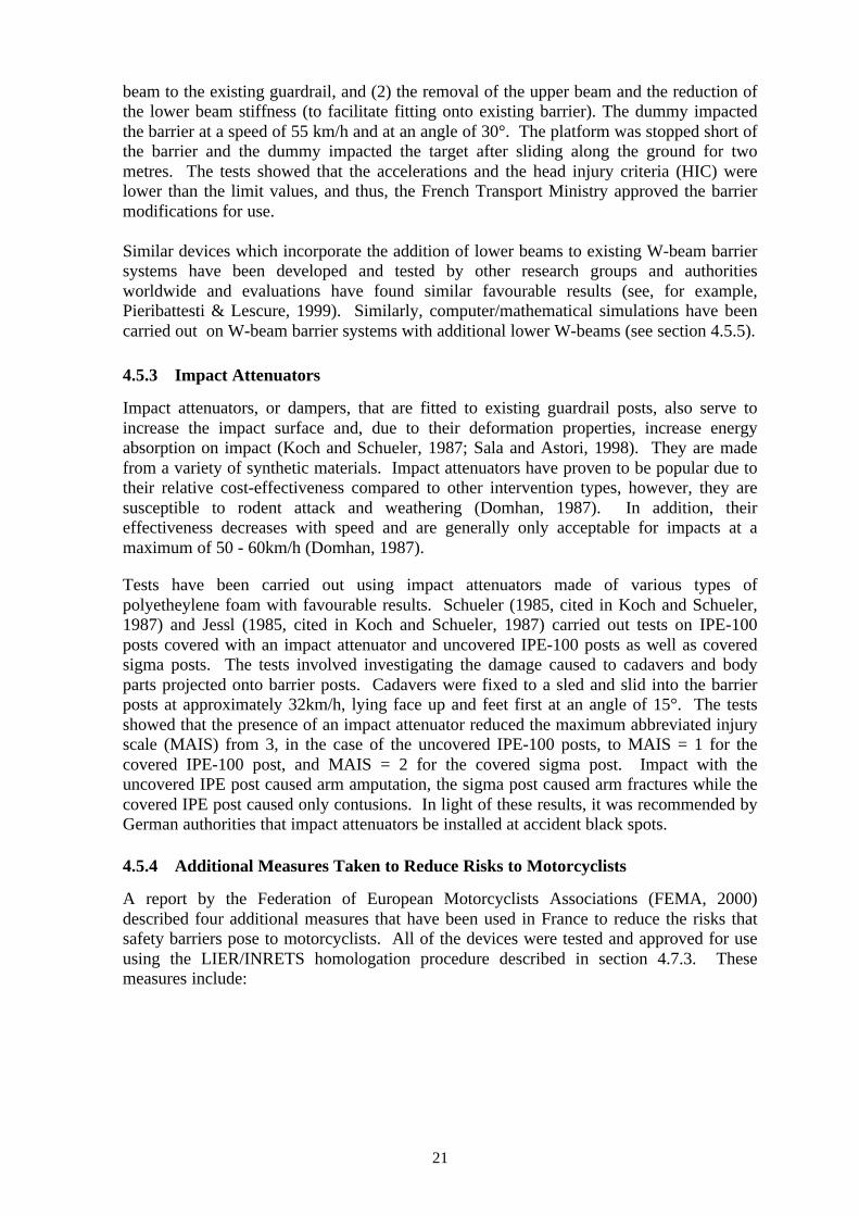
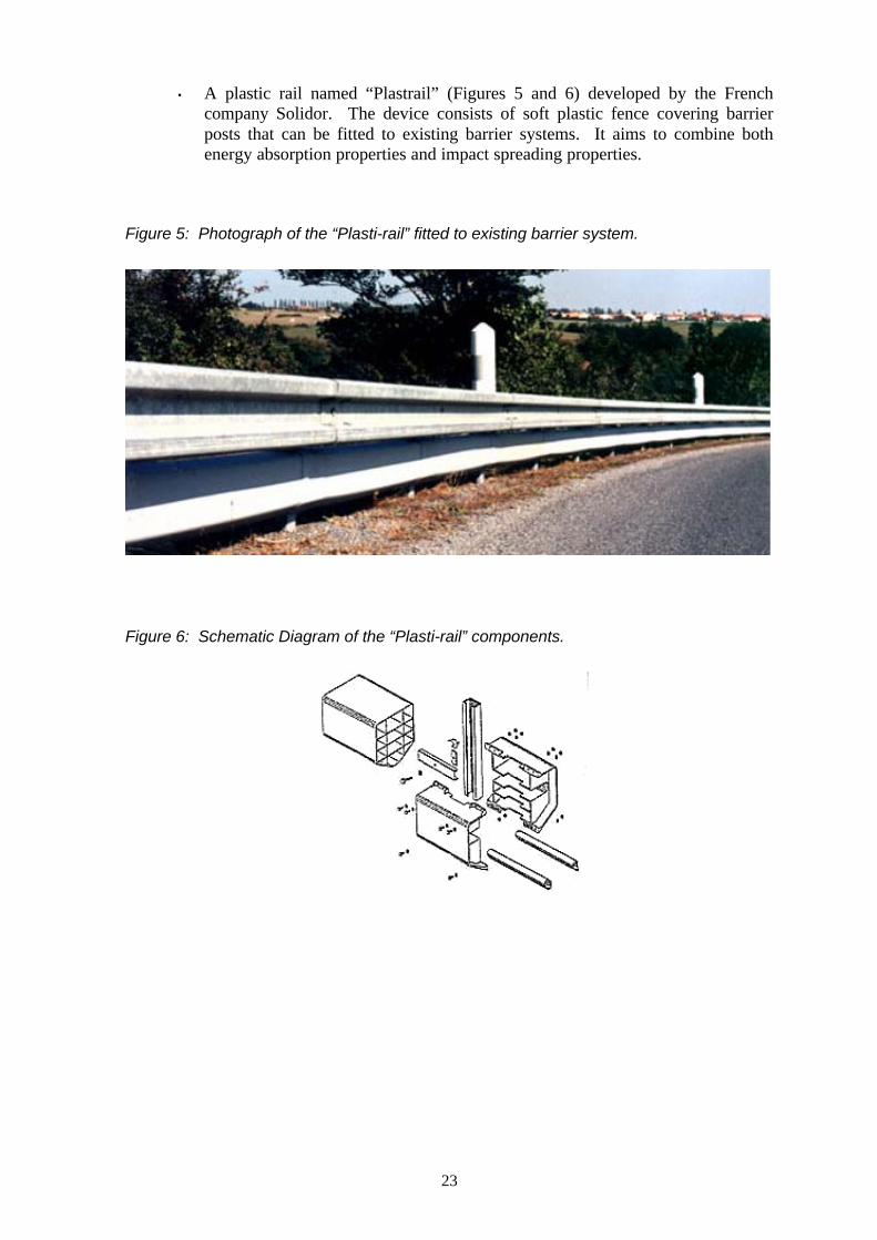
• A plastic rail named “Plastrail” (Figures 5 and 6) developed by the Frenchcompany Solidor. The device consists of soft plastic fence covering barrierposts that can be fitted to existing barrier systems. It aims to combine bothenergy absorption properties and impact spreading properties.
Figure 5: Photograph of the “Plasti-rail” fitted to existing barrier system.
Figure 6: Schematic Diagram of the “Plasti-rail” components.
24
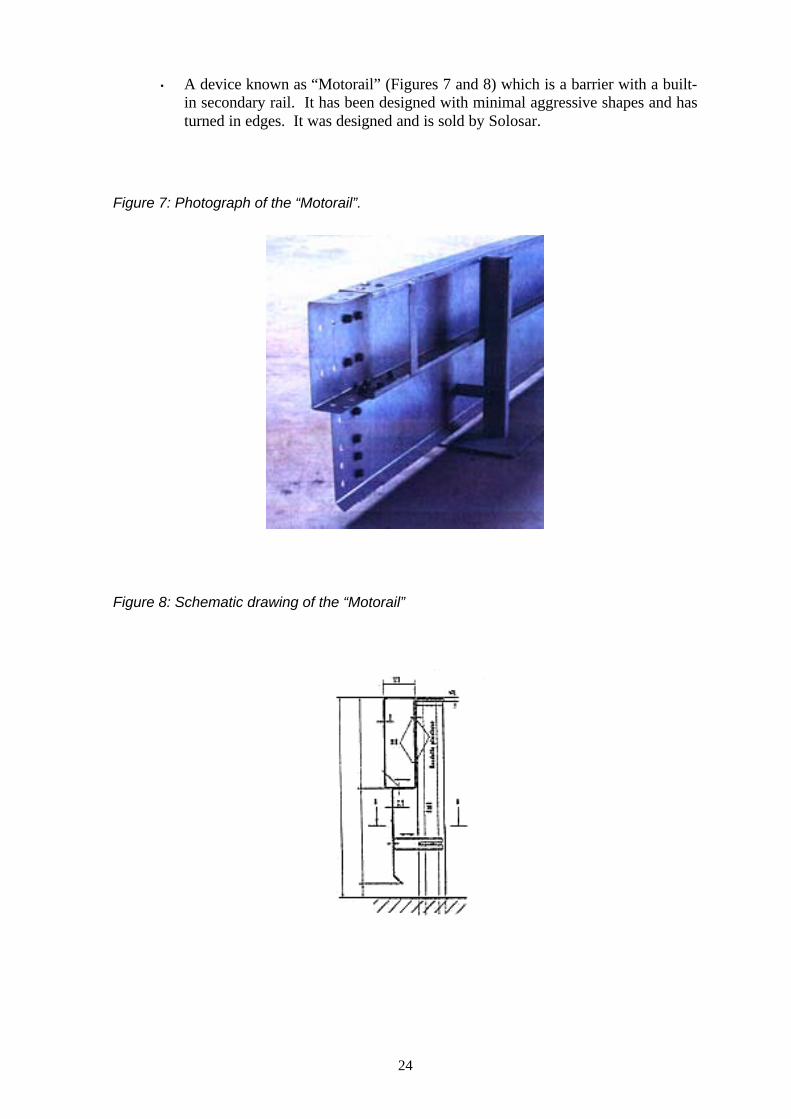
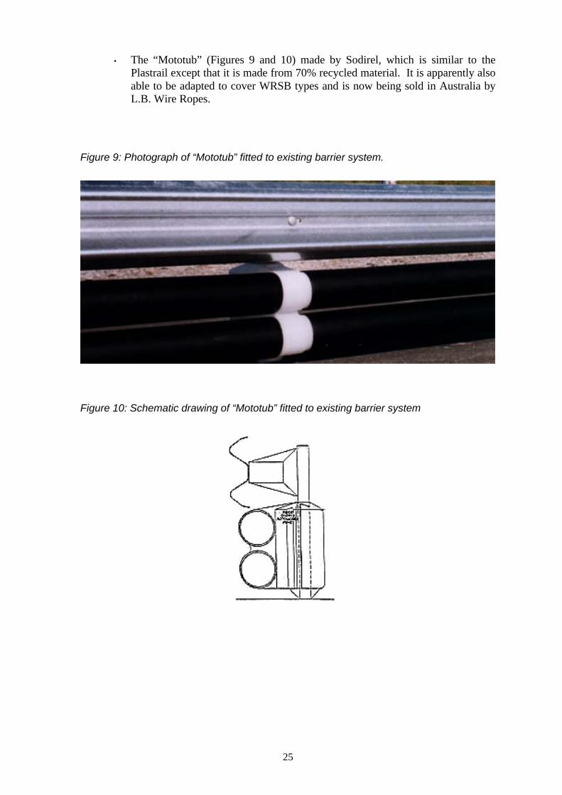
• A device known as “Motorail” (Figures 7 and 8) which is a barrier with a built-in secondary rail. It has been designed with minimal aggressive shapes and hasturned in edges. It was designed and is sold by Solosar.
Figure 7: Photograph of the “Motorail”.
Figure 8: Schematic drawing of the “Motorail”
25
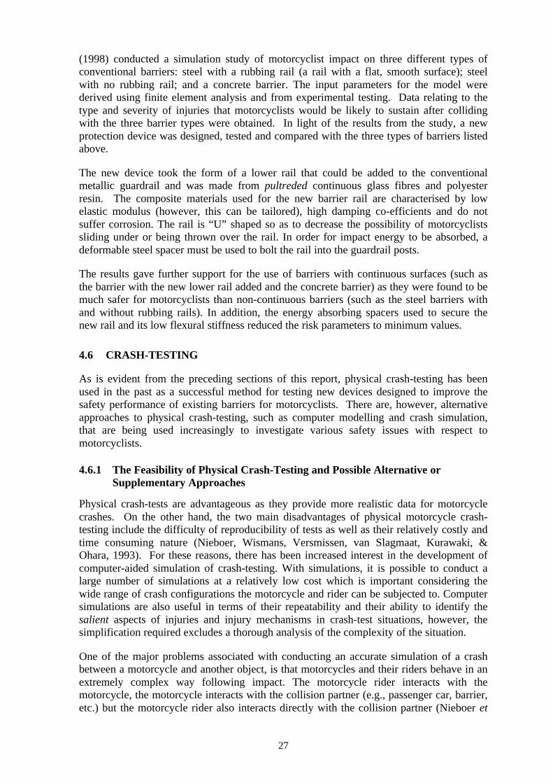
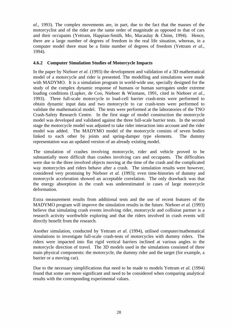
• The “Mototub” (Figures 9 and 10) made by Sodirel, which is similar to thePlastrail except that it is made from 70% recycled material. It is apparently alsoable to be adapted to cover WRSB types and is now being sold in Australia byL.B. Wire Ropes.
Figure 9: Photograph of “Mototub” fitted to existing barrier system.
Figure 10: Schematic drawing of “Mototub” fitted to existing barrier system

26
In addition, the Baltic Construction Company in Sweden has developed a device thatcovers the upper and lower wire rope systems of standard WRSBs (Figure 11). The deviceconsists of aluminium profiles that can be fitted to existing systems. Computer simulationswere conducted to assess the safety performance of the device using the Finite ElementsProgram, LS-DYNA, and included tests using a 16 ton lorry, a 900kg car and a motorcycle(Baltic Construction Company, 1999).
Figure 11: Schematic drawing of aluminium profile covering WRSB
The simulation was set up according to the following conditions:
1. 16 ton lorry – initial velocity of 80km/h, impact angle 20°;
2. 900kg car – initial velocity 100km/h, impact angle 20°, and;
3. Motorcycle – initial velocity 100km/h, impact angle 20°.
The Acceleration Severity Index (ASI), Theoretical Head Impact Velocity (THIV), PostImpact Head Decelerations (PHD), working width and the dynamic deflection (i.e.deflection of the fence) were measured for each configuration. The results, in terms of thesafety performance of the device for motorcyclists, showed that the motorcycle wasredirected by the device and that, as the motorcycle and its rider slid along the fence, thealuminium guides protected the rider body parts against the wires. In addition, no part ofthe fence penetrated the motorcycle or the rider. The simulations involving the carsuggested that all measured variables were within acceptable levels, however, in thesimulation involving the lorry, the vehicle was found to run over the fence, and hence, notall variables could be recorded, although it was found that no fence parts became detachedand penetrated the vehicle.
On the basis of these results, this device appears promising in terms of its potential toreduce injuries to motorcyclists through the so-called “cheese-cutter” effect of WRSBs,however, it does not protect motorcyclists from injuries resulting from impact with theposts of WRSBs. Also, it should be noted that a standard WRSB (without the aluminiumguides) was not included for comparison purposes in the simulation.
4.5.5 Data From Computer and Mathematical Based Simulation Studies
There is additional evidence for the aforementioned interventions from computer andmathematical simulation studies. Using a multi-body numerical method, Sala & Astori
27
(1998) conducted a simulation study of motorcyclist impact on three different types ofconventional barriers: steel with a rubbing rail (a rail with a flat, smooth surface); steelwith no rubbing rail; and a concrete barrier. The input parameters for the model werederived using finite element analysis and from experimental testing. Data relating to thetype and severity of injuries that motorcyclists would be likely to sustain after collidingwith the three barrier types were obtained. In light of the results from the study, a newprotection device was designed, tested and compared with the three types of barriers listedabove.
The new device took the form of a lower rail that could be added to the conventionalmetallic guardrail and was made from pultreded continuous glass fibres and polyesterresin. The composite materials used for the new barrier rail are characterised by lowelastic modulus (however, this can be tailored), high damping co-efficients and do notsuffer corrosion. The rail is “U” shaped so as to decrease the possibility of motorcyclistssliding under or being thrown over the rail. In order for impact energy to be absorbed, adeformable steel spacer must be used to bolt the rail into the guardrail posts.
The results gave further support for the use of barriers with continuous surfaces (such asthe barrier with the new lower rail added and the concrete barrier) as they were found to bemuch safer for motorcyclists than non-continuous barriers (such as the steel barriers withand without rubbing rails). In addition, the energy absorbing spacers used to secure thenew rail and its low flexural stiffness reduced the risk parameters to minimum values.
4.6 CRASH-TESTING
As is evident from the preceding sections of this report, physical crash-testing has beenused in the past as a successful method for testing new devices designed to improve thesafety performance of existing barriers for motorcyclists. There are, however, alternativeapproaches to physical crash-testing, such as computer modelling and crash simulation,that are being used increasingly to investigate various safety issues with respect tomotorcyclists.
4.6.1 The Feasibility of Physical Crash-Testing and Possible Alternative orSupplementary Approaches
Physical crash-tests are advantageous as they provide more realistic data for motorcyclecrashes. On the other hand, the two main disadvantages of physical motorcycle crash-testing include the difficulty of reproducibility of tests as well as their relatively costly andtime consuming nature (Nieboer, Wismans, Versmissen, van Slagmaat, Kurawaki, &Ohara, 1993). For these reasons, there has been increased interest in the development ofcomputer-aided simulation of crash-testing. With simulations, it is possible to conduct alarge number of simulations at a relatively low cost which is important considering thewide range of crash configurations the motorcycle and rider can be subjected to. Computersimulations are also useful in terms of their repeatability and their ability to identify thesalient aspects of injuries and injury mechanisms in crash-test situations, however, thesimplification required excludes a thorough analysis of the complexity of the situation.
One of the major problems associated with conducting an accurate simulation of a crashbetween a motorcycle and another object, is that motorcycles and their riders behave in anextremely complex way following impact. The motorcycle rider interacts with themotorcycle, the motorcycle interacts with the collision partner (e.g., passenger car, barrier,etc.) but the motorcycle rider also interacts directly with the collision partner (Nieboer et
28
al., 1993). The complex movements are, in part, due to the fact that the masses of themotorcyclist and of the rider are the same order of magnitude as opposed to that of carsand their occupants (Yettram, Happian-Smith, Mo, Macaulay & Chinn, 1994). Hence,there are a large number of degrees of freedom in the real life situation, whereas, in acomputer model there must be a finite number of degrees of freedom (Yettram et al.,1994).
4.6.2 Computer Simulation Studies of Motorcycle Impacts
In the paper by Nieboer et al. (1993) the development and validation of a 3D mathematicalmodel of a motorcycle and rider is presented. The modelling and simulations were madewith MADYMO. It is a simulation program in world-wide use, specially designed for thestudy of the complex dynamic response of humans or human surrogates under extremeloading conditions (Lupker, de Coo, Nieboer & Wismans, 1991, cited in Nieboer et al.,1993). Three full-scale motorcycle to load-cell barrier crash-tests were performed toobtain dynamic input data and two motorcycle to car crash-tests were performed tovalidate the mathematical model. The tests were performed at the laboratories of the TNOCrash-Safety Research Centre. In the first stage of model construction the motorcyclemodel was developed and validated against the three full-scale barrier tests. In the secondstage the motorcycle model was adjusted to take rider interaction into account and the ridermodel was added. The MADYMO model of the motorcycle consists of seven bodieslinked to each other by joints and spring-damper type elements. The dummyrepresentation was an updated version of an already existing model.
The simulation of crashes involving motorcycle, rider and vehicle proved to besubstantially more difficult than crashes involving cars and occupants. The difficultieswere due to the three involved objects moving at the time of the crash and the complicatedway motorcycles and riders behave after a crash. The simulation results were however,considered very promising by Nieboer et al. (1993); even time-histories of dummy andmotorcycle acceleration showed an acceptable correlation. The only drawback was thatthe energy absorption in the crash was underestimated in cases of large motorcycledeformation.
Extra measurement results from additional tests and the use of recent features of theMADYMO program will improve the simulation results in the future. Nieboer et al. (1993)believe that simulating crash events involving rider, motorcycle and collision partner is aresearch activity worthwhile exploring and that the riders involved in crash events willdirectly benefit from the research.
Another simulation, conducted by Yettram et al. (1994), utilised computer/mathematicalsimulations to investigate full-scale crash-tests of motorcycles with dummy riders. Theriders were impacted into flat rigid vertical barriers inclined at various angles to themotorcycle direction of travel. The 3D models used in the simulations consisted of threemain physical components: the motorcycle, the dummy rider and the target (for example, abarrier or a moving car).
Due to the necessary simplifications that need to be made to models Yettram et al. (1994)found that some are more significant and need to be considered when comparing analyticalresults with the corresponding experimental values.
29
Also, the sensitivity increases with impact speed, making simulation difficult at velocitiesgreater than about 56 km/h. This is due to the coalescing of critical events at such highspeeds.
Yettram et al. (1994) found that with accurate values for the input data the program willproduce overall displacements and velocities to within an acceptable tolerance.
Another study, conducted by Chinn, Okello, McDonough and Grose (1996) in the UnitedKingdom, successfully used a combination of, among other things, computer simulation(using MADYMO), initial sled tests and full-scale impact tests to develop a testingprogram for a purpose-built airbag restraint system for motorcycles.
MADYMO was used to investigate rider kinematics at impact using load and accelerationimpact test data information that had been supplied by the Transport Research Laboratory,UK. The sled tests were conducted in order to evaluate the test system, with a dummyrider, over a range of parameters covering speed, angle and seating positions. The finalphase of the project, which was incomplete at the time of publication of the report, wasfull-scale crash-testing, carried out in accordance with the current standards for conductingmotorcycle crash-tests (ISO DIS 13232) (Van Driessche, 1994). The crash-tests wereconducted at the Transport Research Laboratory using a computer controlled hydraulicmotor-drive system with the capacity to achieve highly accurate test speeds with lowacceleration of the trolley (Chinn et al., 1996).
The authors conclude that the process of development, which begins with computersimulation and proceeds to design, development and evaluation using tests such as sledtests and full-scale crash-tests, has proven to be very efficient and effective.
4.6.3 Sub-system/Component Testing
Another alternative or supplementary approach to physical crash-testing and/or crashsimulation is sub-system or component testing. This method focuses on specific crashcomponents, of both the human body and isolated barrier parts, which are believed to becritical to injury severity outcomes. Hence, it provides a way of testing specific parametersat a relatively low cost. It is also a way of breaking down a very complex problem into“easy to handle” parameters, which is useful when certain criteria need to be measured.
In the case of motorcycle riders interacting with roadside barriers, it is important toidentify the specific injury mechanisms that may cause death or serious injury to the rider.Once this is done, a number of sub-system tests can be developed to measure what is foundto be important indicators of injury, such as head acceleration.
To be able to determine what type of injuries riders sustain when they come into contactwith roadside barriers, it is important to look at real world crashes. Only real worldcrashes produce the necessary injury statistics that can be used to identify the specificinjury producing factors that play a part in the interaction between rider and barrier. Whenthe injury producing factors have been found, it is possible to set up a number ofguidelines, which aim to reduce or eliminate the potential of serious injury or death. Anumber of sub-system tests can then be designed around the guidelines in order to be ableto measure the performance and possible benefits from different barrier designs.
Sub-system testing is used in many ways, for example, in motorcycle helmet testing.Helmets are tested on the specific, potential injury producing factors for which they are
30
designed to address. With special tools, helmets are tested on their ability to absorb energyand protect from penetration. The same principle of testing is used in sub-system testing ofcars to measure their potential injury producing effect in collisions with pedestrians.
In a report by Grösch and Hochgeschwender (1989), sub-system testing of car/pedestriancollisions is described. One of the reasons why the authors chose to do component testingis that the large number of impact configurations requires an inordinately large number oftests. This problem can also be found in motorcycle crash-testing, indicating somesimilarities with pedestrian testing. Certain parameters, which may also be useful inbarrier testing, are measured in, for example, the head to bonnet component test. The aimsof the parameters are:
§ Maximum deformation of the component;
§ The smallest possible peak force;
§ The most even distribution of forces possible.
All of the different parameters are measured with relevant parts of the dummy mounted tothe pendulum of the impactor. The relevant dummy parts were, in this case, the head,lower leg and femur. The results of these tests are recognised as only a rough guide to theinjury risk of a human in a comparable accident situation.
Another sub-system test was done by MacLaughlin and Kessler (1990). The reportdescribes a head impact test with a uniaxial head impactor. The impactor was able toidentify which of nine passenger cars and three light trucks would cause pedestrian headimpact injury in the event of a car/pedestrian collision.
Ishikawa, Yamazaki, Ono and Sasaki (1991) conducted parametric studies with sled testsand computer simulations in order to understand pedestrian kinematics in car/pedestriancollisions. Ishikawa et al. (1991) also looked at accident analyses and full-scale tests toobtain data for considering sub-system test methods for pedestrian protection.
Component testing with leg impactors was carried out by Sakurai, Kobayashi, Ono andSasaki (1994), to determine the influence of upper body mass on leg impact and tocompare direct and indirect measuring methods when determining potential leg injury.
In 1987 the European Experimental Vehicles Committee (EEVC) set up Working Group10 (WG10) which presented a proposal for a test method to evaluate pedestrian protectionfor cars (Harris, 1991). The work of WG10 was finalised in 1994.
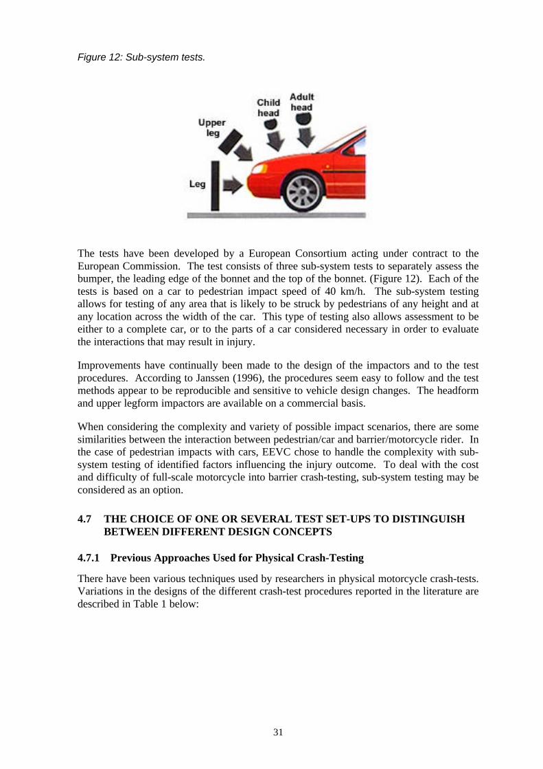
31
Figure 12: Sub-system tests.
The tests have been developed by a European Consortium acting under contract to theEuropean Commission. The test consists of three sub-system tests to separately assess thebumper, the leading edge of the bonnet and the top of the bonnet. (Figure 12). Each of thetests is based on a car to pedestrian impact speed of 40 km/h. The sub-system testingallows for testing of any area that is likely to be struck by pedestrians of any height and atany location across the width of the car. This type of testing also allows assessment to beeither to a complete car, or to the parts of a car considered necessary in order to evaluatethe interactions that may result in injury.
Improvements have continually been made to the design of the impactors and to the testprocedures. According to Janssen (1996), the procedures seem easy to follow and the testmethods appear to be reproducible and sensitive to vehicle design changes. The headformand upper legform impactors are available on a commercial basis.
When considering the complexity and variety of possible impact scenarios, there are somesimilarities between the interaction between pedestrian/car and barrier/motorcycle rider. Inthe case of pedestrian impacts with cars, EEVC chose to handle the complexity with sub-system testing of identified factors influencing the injury outcome. To deal with the costand difficulty of full-scale motorcycle into barrier crash-testing, sub-system testing may beconsidered as an option.
4.7 THE CHOICE OF ONE OR SEVERAL TEST SET-UPS TO DISTINGUISHBETWEEN DIFFERENT DESIGN CONCEPTS
4.7.1 Previous Approaches Used for Physical Crash-Testing
There have been various techniques used by researchers in physical motorcycle crash-tests.Variations in the designs of the different crash-test procedures reported in the literature aredescribed in Table 1 below:
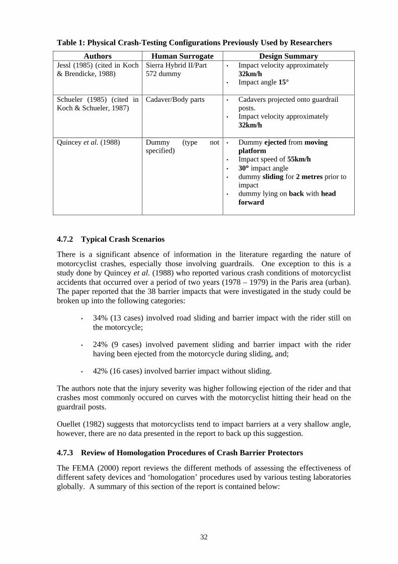
32
Table 1: Physical Crash-Testing Configurations Previously Used by Researchers
Authors Human Surrogate Design SummaryJessl (1985) (cited in Koch& Brendicke, 1988)
Sierra Hybrid II/Part572 dummy
• Impact velocity approximately32km/h
• Impact angle 15°
Schueler (1985) (cited inKoch & Schueler, 1987)
Cadaver/Body parts • Cadavers projected onto guardrailposts.
• Impact velocity approximately32km/h
Quincey et al. (1988) Dummy (type notspecified)
• Dummy ejected from movingplatform
• Impact speed of 55km/h• 30°° impact angle• dummy sliding for 2 metres prior to
impact• dummy lying on back with head
forward
4.7.2 Typical Crash Scenarios
There is a significant absence of information in the literature regarding the nature ofmotorcyclist crashes, especially those involving guardrails. One exception to this is astudy done by Quincey et al. (1988) who reported various crash conditions of motorcyclistaccidents that occurred over a period of two years (1978 – 1979) in the Paris area (urban).The paper reported that the 38 barrier impacts that were investigated in the study could bebroken up into the following categories:
• 34% (13 cases) involved road sliding and barrier impact with the rider still onthe motorcycle;
• 24% (9 cases) involved pavement sliding and barrier impact with the riderhaving been ejected from the motorcycle during sliding, and;
• 42% (16 cases) involved barrier impact without sliding.
The authors note that the injury severity was higher following ejection of the rider and thatcrashes most commonly occured on curves with the motorcyclist hitting their head on theguardrail posts.
Ouellet (1982) suggests that motorcyclists tend to impact barriers at a very shallow angle,however, there are no data presented in the report to back up this suggestion.
4.7.3 Review of Homologation Procedures of Crash Barrier Protectors
The FEMA (2000) report reviews the different methods of assessing the effectiveness ofdifferent safety devices and ‘homologation’ procedures used by various testing laboratoriesglobally. A summary of this section of the report is contained below:
33
• LIER/INRETS homologation test for secondary rail: a dummy is thrown,head first sliding on its back, against a fitted barrier with an impact speed of60km/h ± 5% at a 30° angle ± 0.5°. The criterion for homologation is HIC <1000 (note: the surface of the road was required to be made slippery for thedummy to actually reach the barrier due to the significant reduction of speedcaused by the motorcyclist sliding along the ground prior to impact).
• German Federal Bureau for Road Safety (BASt) homologation procedurefor impact protector: Deceleration against crash barrier protector duringimpact, which should not exceed 60g as a peak value and 40g over a 3msinterval, is measured. The report states that different methods are used to assesstwo classes of devices (class one are tested with an impact speed of 5.5m/s or20km/h, and class 2 with an impact speed of 9.7m/s or 35km/h), however, itdoes not divulge the nature of these two classes of devices or any other detailsof the method used.
The FEMA (2000) report acknowledges the difficulty in comparing the effectiveness ofdifferent safety devices used due to the fact that the devices have been tested with differentmethods and criteria. The document reports on a discussion held with Dr. Michelle Rametfrom INRETS in France who points out the need for a study that compares different typesof barrier and barriers fitted with safety devices in comparable conditions.
4.8 THE CONDUCT OF PHYSICAL CRASH-TESTING
4.8.1 Crash-Testing Guidelines
In the event of a decision to conduct physical crash-testing either in isolation or inconjunction with computer or mathematical modelling techniques, there are certainguidelines that have been developed for such purposes. Guidelines were developed by agroup of motorcyclist safety experts, appointed by the International Organisation forStandardisation (ISO) in response to the need for an internationally recognised researchmethodology to be developed regarding motorcycle safety research (see Van Driesseche,1994). The guidelines cover factors such as suitable crash-test dummies, physicalmeasurements to be taken, injury assessment variables, instrumentation and measurementspecifications. Although the recommendations apply primarily to the evaluation ofspecific devices to be fitted to motorcycles for the protection of riders, many of therecommendations apply to other crash-testing programs. Relevant sections of the reportare outlined below.
4.8.2 The Choice of a Suitable Human Surrogate for Testing
A specialised crash-test dummy for motorcycle crash-testing has been developed and isspecified in ISO 13232. The basis dummy recommended by the ISO for motorcycle crash-testing is a Hybrid III 50th percentile male dummy with sit/stand construction, standardnon-sliding knees and head/neck assembly compatible with either a 3-or 6-axis upper neckload cell. However, the Hybrid III dummy was developed for purposes other thanmotorcycle crash-testing, for example, simulating restrained car occupants in frontalimpacts. The Hybrid III dummy has limited means to assess some of the main factors inmotorcycle crashes due to the biofidelity characteristics being specialised for their originalintended function. To transform the Hybrid III dummy into an ISO 13232 motorcyclistdummy, thereby making it useful in motorcycle crash-testing, certain modifications arerequired. These include:
34
1. Motorcyclist dummy head skins must be extended to provide surfaces for thehelmet retention strap under the chin and the back of the neck-helmet contact.
2. Motorcyclist dummy neck components, including: a neck shroud, whichprovides an appropriate reaction surface between the neck and external objects.A lower neck mount, which is needed to increase the neck extension adjustmentpossibilities to accommodate forward leaning riding styles. A modified noddingjoint, which with the modified lower neck mount, provide maximumadjustability for the positioning of the dummy head and improved upper necktorsional characteristics.
3. Motorcycle dummy thorax components, including provisions for areplacement thoracic spine, which is compatible with the internal dataacquisition system. A slightly modified chest skin and a modified straightlumbar spine are important for many reasons such as e.g., provide an uprightseating position on a motorcycle and provide appropriate weight formaintaining the proper Hybrid III centre of gravity and mass.
4. Motorcycle dummy abdominal insert, which provides a physical record ofmaximum residual deformation. The deformation allows the dummy to showthe potential abdominal injuries as a result of penetration into the abdominalinsert.
5. Sit/stand pelvis, which may contain parts of the internal data acquisitionsystem. Even if part of the system is located in the pelvis it is a requirement thatthe Hybrid III sit/stand characteristics remain unchanged.
6. Modified elbow bushing allowing for proper positioning of the elbow andpreventing over-centre locking of the elbow, which would distort realistic torsomotion.
7. Motorcyclist dummy hand components with deformable aluminium wires asinternal structure, which allow the dummy to ‘grasp’ the handlebars, and hence,aid in stabilising the dummy on the vehicle as well as providing realisticdummy to handlebar force properties.
8. Motorcyclist dummy upper-leg components including a frangible femur boneand associated mounting hardware. In order to achieve human-like impact forcelevels up to fracture point and human-like trajectory after fracture, it isnecessary to have frangible bones with human-like stiffness and strength. Thebones used in the ISO 13232 motorcyclist dummy are composite bonesdescribed in St Laurent Shewchenko and Szabo (1989) and Newman, Zellnerand Wiley (1991). The rigid metal leg bones used in the Hybrid III areinappropriate to use in motorcycle crash research because they were designedwith a very different type of crash in mind. The Hybrid III leg bones aredesigned to measure frontal impacts most often to the knee but in motorcyclecrash-testing the leg bones are exposed to multiple impacts from all directions.
Another problem with the Hybrid III leg bone is large overestimation offracture potential. In comparison with human cadaver lower leg bone orfrangible composite lower leg bone, the rigid metal lower leg bone of theHybrid III can result in a 100%, or more, overestimation of impact forces i.e.,
35
fracture potential. As a result of the Hybrid III leg bones not fracturing thedummy motions may, in some cases, be distorted as compared to the motionsproduced with frangible human or dummy leg bones.
9. Motorcyclist dummy frangible knee assembly, which is included to measurethe possibility of knee ligament injuries in lateral bending and monitor torsionrelative to the tibia. A frangible knee assembly also provides realisticmovement and allows for measuring of the forces between the lower and upperlegs, as well as providing enhanced biofidelity with regards to the potentiallylarge torsional load in the femur.
For this frangible knee concept, a failure of an internal shear pin is interpretedas an injury of the respective knee ligament.
10. Leg retaining cables to prevent the loss of the dummy legs in the case offrangible bone fracture because the loss of a leg during a crash-test mayinfluence the overall movement of the dummy.
11. Motorcyclist dummy lower-leg components, which includes a frangible tibiabone. The same issues are relevant here as in the case of the frangible femurbone except for the tibia axial characteristics.
12. Modified lower leg skin, which is needed in order to provide for the removaland installation of the skin on the frangible leg bones.
13. Sampling of frangible components, to allow for performance specification ofpotentially different frangible component designs and to ensure that thevariability in frangible components is controlled to a feasible minimum.
A full description of the recommended dummy with all of the relevant modifications aswell as its electronic configuration can be found in Zellner et al. (1996).
4.8.3 Review of the Physical Measurements that may be Obtained from Crash-TestDummies to Assess Injury Severity
This section reviews the injury assessment variables that are required for quantifying theprobability of injury for the various parts of the body.
HeadThe injury assessment variables for the head include; the maximum generalisedacceleration model for brain injury tolerance (GAMBIT), which is used to quantifycombined linear and angular acceleration effects as related to the probability of braininjury; Head Injury Criteria (HIC); and the maximum resultant linear acceleration, whichshould be taken for reference with, and comparison to, computer simulation research.
ChestFor the chest, the injury assessment variables are the upper and lower sternum maximumnormalised-compression and the upper and lower sternum maximum velocity-compressioninjury variables. These are considered to be preferable to acceleration-based chest impactsbecause they are more directly related to observed injury mechanisms in humans.
36
AbdomenThe maximum residual deformation is the injury assessment variable for the abdomen.
NeckExtra injury assessment variables (including the x – z trajectory of the helmet, the resultantvelocity at first helmet/opposing vehicle contact and longitudinal, lateral and verticalvelocities at first helmet/opposing vehicle contact) are suggested for research into headprotective devices. However, as neck trauma is claimed to be relatively infrequent innormal accident data (Van Driesseche, 1994), these variables may not be required in theproposed research project.
Lower Extremity InjuriesDisplaced and non-displaced bone fractures and, knee partial and complete dislocation.
Injury Severity ProbabilitiesWeibull functions are used to model the probability associated with each AIS level for agiven body region.
Injury IndicesThe injury indices include: the probability of each discrete AIS injury severity level for thehead, thorax, abdomen and lower extremities; the probability of fatality; the risk of lifethreatening brain injury based on HIC; the medical and ancillary costs associated withinjuries to each of the four body regions; the probable AIS for each body region basedupon the weighted average of each AIS probability; the normalised injury costs of survivaland fatality; and the total normalised injury cost.
4.9 VARIABLES TO BE MEASURED, INSTRUMENTATION &MEASUREMENT PROCEDURES
4.9.1 Electronic Recorded Variables
For full-scale impact tests, it is recommended that the entire impact sequence berecorded, including: time of first motorcycle/opposing object (MC/OO) impact; nine linearhead accelerations (in order to compute the three linear and three angular accelerations ofthe head centre of gravity); and four sternum displacements (two upper, two lower).
Head protective device research: the upper neck x, y z forces and y and z movements arerequired to provide some indication for the potential for neck injury.
Leg protective device research: the upper femur axial force and the lateral and antero-posterior (AP) bending movements and the upper-tibia lateral and AP bending movementsare required for both legs. The leg sensors are required to provide information regardingcause/effect relationships rather than as an injury index, as this is indicated by frangiblebone fracture.
Other variables that may be recorded include: upper neck forces and movements; lumbarspine forces and movements; upper and lower femur lateral and AP bending movements;
37
torsional movement and axial force; upper- and lower-tibia lateral and AP bendingmovements, torsional movement and axial force.
Due to biofidelity limitations of the dummy, it is recommended that chest and pelvicacceleration not be recorded, as it may lead to misleading data.
4.9.2 Mechanically Recorded Variables
In full-scale tests the following mechanical variables must be recorded and photographed:abdomen maximum penetration, left and right femur fracture occurrence; left and rightfemur fracture occurrence; left and right knee varus valgus and torsional dislocationoccurrence; and left and right tibia fracture occurrence.
4.9.3 Photographic Targets To Be Digitised
In order to quantify head injury potential variables, the helmet centroid point (the centre ofa circle circumscribed about the helmet) during the primary impact period is required. Inaddition, in order to provide measurements and verification that the speeds and contactpoints are within the specified tolerances, the targets on the opposing vehicle, dummyjoints, and the ground prior to the first MC/OO impact are required. These targets are to bedigitised.
4.9.4 Sensor Specifications
The specific electronic sensors required include: head accelerometers; upper-neck loadcell, chest potentiometers; lumbar load cell; upper-femur load cells; and frangible load cellstrain gauges. The sensors used should be compatible with the Hybrid III basis dummy (ifthis is to be used). Mechanical sensors include: the abdominal foam insert; frangible femurand tibia bones; knee compliance elements; and knee sheer pins.
38
5 CONSULTATION WITH STAKEHOLDERS
5.1 QUEENSLAND
Attendees: Main Roads Queensland (Lloyd Davis, Senior Multidisciplinary Engineer,Transport Technology Division; Mark Olive, Engineer (Traffic), Transport TechnologyDivision; Paul Grice, Assistant to Principal Engineer (Development Control), MetropolitanDistrict.)
These discussions were held on Monday 10 July 2000, and provided both policy andoperational perspectives from the Main Roads staff involved. The main issues arising fromthe discussions, as they relate to the current project, may be summarised as follows:
§ Useful sources of information include:
§ Australian Standard (AS/NZS 3845: 1999) for Road Safety Barrier Systems;
§ Austroads Guide to Traffic Engineering Practice, Part 15 (initial release May2000);
§ INRETS Website;
§ Motorcycle Riders Association Website in Australia and the UK;
§ NCHRP Report 350 (US crash-testing standard);
§ PREN 1317 (European crash-testing standard);
§ Main Roads Design Guide;
§ Barrier manufacturers for their crash records;
§ Motorcycle racing videos to observe the range of crash scenarios that occur inthis sport, that might also be expected on public roads.
§ The design objective for barrier systems in impacts with motorcyclists should be formotorcyclists to be contained and redirected by the barrier, rather than be allowed topass under, through or over the barrier. The main reason for this is to preventsubsequent impact with hazards that lay beyond the barrier;
§ The preferred strategy is to manage motorcyclist injury risk by redirecting riders. Thishas been attempted by using a (lower) rubbing rail fitted below the main rail to preventriders going underneath the barrier and suffering injuries while, or after, passing underthe barrier (for example, the snagging of a rider helmet between the barrier and theroad surface causing severe head injuries was noted as an injury mechanism). Such afeature also has the potential to reduce injury severity due to contact with barrier posts.In French designs, the rubbing rail presents a flat, smooth surface, in the Austroads
39
guide, a second W-shaped beam is recommended, while in some German experiments,twin tubes (possibly of the Mototub design described in section 4.5.4) have beeninstalled by riders themselves, with approval by road authorities;
§ The majority of motorcyclist impacts with barriers involve riders sliding across (orotherwise traversing) the pavement after leaving their motorcycles. Therefore, anyfuture research should focus on this scenario rather than the situation where the riderand bike together strike the barrier, with the bike more or less upright. Typical impactangles are around 12°, though US and European test standards might involve impact ofaround 20-25° for general barrier testing, thereby capturing information on more severecrash scenarios.
§ A particular safety concern with barriers is the use of reflectors which sit above or outfrom the barrier (known as “butterfly” reflectors). This problem is being addressedthrough the use of reflector types which are fitted within the middle “V” of the W-beam or, alternatively, reflectors fitted to a frangible mounting pipe have been used toallow the reflectors to break off if struck during impact.
§ Posts used to support wire rope barriers have been made more frangible by reducingdesign thickness of the s-shaped cross-section to 6mm. Barrier manufacturers haveindicated that no further reduction can occur without overall performance of the barrierbeing compromised. With regard to posts used to support W-beam barriers, there islittle scope to reduce their dimensions without affecting post installation practices(posts are driven into the ground and may be damaged if weaker designs are used).
§ A number of practical considerations, believed to contribute to crash and injury risk formotorcyclists, include:
§ Arrows and other pavement markings, as well as use of pavement crack sealant,especially in the vicinity of curves or other areas where high levels of skidresistance are required;
§ Optimal placement of noise walls (for successful noise attenuation) along high-speed roads such as freeways/expressways, can interfere with optimalplacement of roadside barriers for safety reasons. In such cases, safety barriersmay need to be located within the desirable minimum 9m clear zone. Similarly,the achievement of grades of less than 10%, as specified by barrier designs, canalso result in placement of barriers closer than the desired 2m minimum offset.
§ Motorcyclist involvement in any future research activities in this field is encouraged toobtain direct user input, while helping to ensure that the requirements of all road users(truck drivers, bus passengers, other vehicle occupants, etc.) receive due recognition.The Harley Owner’s Group (HOG) and Ullysses (motorcyclists aged 50 years andover) were mentioned as potential groups with whom to consult in any future stages ofthis research.
40
5.2 VICTORIA
Attendees: VicRoads (Warwick Pattinson, Sam Pirotta and Rod Howard), Victoria Police(Sergeant Steve Lomas, Senior Constable Colin Chamings), Representative from theFederal Motorcycle Coalition (Michael Czajka).
These discussions were held on Tuesday 29 August 2000. The main issues arising fromthe discussions, as they relate to the current project, may be summarised as follows:
CRASH PROBLEM
§ VicRoads reported that wire rope barriers have been used overseas for over 30 yearswith few reported injuries from impacts and that there are no known cases of casualtycrashes in Victoria.
§ There is a problem of under-reporting of run-off-the-road motorcycle crashes ingeneral, which may in turn suggest that there is under-reporting of motorcyclistimpacts with barriers. However, it is probable that the crashes that are not beingreported (if this is the case) are of a less serious nature due to the fact that any crashrequiring medical assistance will be reported. Further, when crashes are actuallyreported, identification of barrier type tends to be inadequate for detailed study.
§ Despite the potential for under-reporting of crashes, the problem of motorcyclistimpacts into barriers appears to be a relatively small part of the total road safetyproblem. However, among motorcycle crashes, rider impacts with barriers, particularlybarrier posts, are a serious concern in terms of the potential for serious injuries.
§ There is a distinct lack of data available for an adequate understanding to be developedregarding the nature of motorcyclist impacts with barriers (i.e., the identification of oneor more “typical” crash scenarios). It was suggested that video footage of motorcyclistcrashes in motorcycle races such as the Grand Prix could be studied to gain furtherinsight into the nature of motorcycle crashes. Another suggested source of informationwas the study conducted by Haworth, et al., (1997).
§ It was also suggested that crash data could be investigated to identify where motorcyclecrashes typically occur on Victorian roads. Potential sources of information include:Corben, Gelb, Pronk and Fitzharris (1999), and the Motorcycle Countermeasures report(Haworth et al.,1997). Also, the VicRoads Road Crash Information System, availableon-line and which provides details of accidents including exact locations, may beanother possible source of information.
REDIRECT THE RIDER OR ALLOW RIDER TO PASS THROUGH BARRIER
§ The issue of when and where to install barriers was discussed in terms of ensuring thatthe installation of barriers should be limited to locations where the injury consequencesof hitting the barrier will be less than if there were no barrier installed. In addition, theissue of alternative types of barriers was discussed, for example, the use of smallshrubs and sand arrestor-beds, either between the road and the barrier or in lieu of thebarrier itself. It was acknowledged that there are practical issues with theseinterventions, however.
41
§ The general views expressed were that barriers should be designed to retain ridersrather than allow them to pass through, over or under the barrier. The two mainreasons for this view were:
1. It is reasonable to expect that if a barrier has been installed, that there is somesort of serious hazard beyond the barrier. Therefore, retaining and redirectingthe rider should protect him/her from the hazardous environment beyond thebarrier.
2. It is believed that it is unlikely that a sliding or tumbling motorcyclist (havingseparated from their bike) would have enough control to successfully avoidimpacting with a post on the way through/under the barrier system.
§ Also, it was felt that as riders generally impact barriers at shallow angles, the likelihoodof the rider eventually hitting a post will be high, despite the fact that there are somebarrier systems that allow for greater spacing between posts.
DESIGN FEATURES/INJURY MECHANISMS
§ The barrier posts were regarded as the most dangerous feature of guardrail systems.The sharp edges along the top and sides of W-beam barriers were also consideredparticularly hazardous.
§ Despite the rigidity of concrete barriers, they were considered to be preferable to otherbarrier types when hit at a shallow angle, as they have a smooth continuous surface andhave the potential to distribute forces over a larger surface area. This was also the viewexpressed in Czajka (2000), where it was mentioned that the absence of protrusions andthe smooth surface of concrete barriers makes them preferable to motorcyclists thanother barrier types. However, adding holes or protrusions to this barrier type increasesthe possibility of vehicles or riders becoming caught on them, thus decreasing barriersafety performance.
§ A suggestion that would possibly improve existing W-beam systems was to add asmooth-surfaced rail or cap to the top of the W-beam barriers and to make the railingcontinuous all the way to ground level. Also, in the case of WRSBs, it was suggestedthat a continuous sheath that covers the barrier system could be developed to helpreduce injures that result from sliding along the ropes or into the posts.
§ The height of guardrail systems was also identified as a potentially hazardous featureof barriers especially when riders hit the barriers while still on their motorcycle andthere is a hazardous environment on the other side of the barrier (for example, it wasmentioned that a situation exists where trees have been planted on the “non-traffic”side of concrete barriers which may pose a threat to any motorcyclist that is catapultedover the top of the barriers). However, no specific solutions were offered regarding theheight issue.
TEST PROCEDURES AND PHYSICAL MEASURES
§ Angles of impact in real-world crashes were generally believed to be quite shallow,usually around five to ten degrees with a maximum of about 15°.
§ The more speed that can be shed by a rider prior to impact, the less severe the injuriesare likely to be.
42
§ It was suggested that measurement of the injury severity of body areas such as limbsshould be considered in addition to head, neck and chest injury measurement.
§ There may be some value in looking at the types of injuries sustained by riders whohave hit other types of objects such as trees, poles, embankments etc., in order tofurther understand the injury mechanisms.
TEST CONFIGURATION
§ In answer to the question of whether the worst-case scenario or, one or several typicalcrash scenarios, should be investigated in physical crash-testing, it was felt that a moredetailed understanding of crash scenarios may be required before a decision can bemade.
HUMAN SURROGATE
§ The crash-test dummy modified for motorcycle crash-testing, as specified in ISO13232, was thought to be the best option for use in a crash-testing program.
§ It was suggested that careful thought should be given to the clothing worn by thedummy in the crash-tests. The dummy could wear full-leathers, including boots andgloves, or more commonly worn attire such as motorcycle rider jackets (other thanleather) and jeans. Clearly, numerous possibilities exist.
CRASH-TESTING AND CRASH SIMULATION MODELLING
§ Due to the expensive nature of physical crash-testing, it may be more viable toconcentrate on crash simulation modelling approaches and use a smaller physicalcrash-testing program for validation purposes only.
5.3 NEW SOUTH WALES
Attendees: Roads and Traffic Authority, NSW (James Holgate, Ross Dal Nevo, ColinJackson, Steve Williamson and Michael Brauer), NSW Police Service (Sergeant PeterJenkins), NSW Motorcycle Council (Paul Wilton, Greg Hirst).
These discussions were held on Thursday 7 September 2000. For logistical reasons, threemeetings were held addressing each group separately. In addition, telephone discussionswere held with Derek Wainohu Laboratory Manager, RTA CrashLab. The main issuesarising from these discussions, as they relate to the current project, may be summarised asfollows:
CRASH PROBLEM
§ No scientifically-based information exists on the comparative performance formotorcyclists of the main barriers types in use, namely concrete, steel W-beam andwire rope. Such information is needed to guide future use of barrier types to enhancethe safety of motorcyclists, as well as other road user groups.
§ There is a lack of specificity with current crash coding and reporting. In terms ofbarrier systems, the current method distinguishes between only concrete/New Jerseykerbs and guardrails/fences. More specific coding and reporting rarely occurs.
43
§ The RTA and the NSW Police expressed the view that, in road safety terms, theproblem of motorcycle impacts with barriers appears to be relatively small.
§ It was the opinion of all three groups consulted that a study designed to gather moreinformation regarding the details of motorcycle crashes (especially run-off-the-roadcrashes) would be of great benefit. All three groups expressed support for such astudy, however the NSW Motorcycle Council representatives stressed their preferencethat such a study should not take precedence over an investigation into the safety ofbarriers for motorcyclists. It is understood that the NSW Motorcycle Council hasengaged Human Impact Engineeering to analyse NSW Coroner’s records ofmotorcyclist crashes over a five-year period in an effort to better define the crashproblem and hence provide guidance on the focus of future testing.
§ RTA found no match between motorcycle crash sites and road locations with WRSBs,although this has not been done for other barrier types, such as W-beam guardrail.
§ It was suggested that more information regarding the extent to which guardrails mayhave been involved in previous motorcycle crashes may be gained by closerexamination of Police crash records on a case-by-case basis. Peter Jenkins indicatedhis willingness to assist, where possible.
REDIRECT THE RIDER OR ALLOW RIDER TO PASS THROUGH BARRIER
§ It was generally agreed by all parties that barriers should be designed to retain andredirect the rider rather than to allow them to pass through, based on the assumptionthat the barrier has been installed to protect road users from a potential hazard thatexists beyond the barrier. This was especially relevant for median barriers whereallowing a rider to pass to the other side of a barrier may place them in the path ofoncoming traffic.
DESIGN FEATURES/INJURY MECHANISMS
§ The RTA believed that the poor energy transfer properties of concrete barriers may beunderestimated by motorcyclists, especially at higher impact angles. In addition, otherroad users would experience higher injury severity from the substitution of concretebarriers in the place of WRSBs. The Motorcycle Council believed that the problemswith energy-sharing properties (such as with concrete barriers) presents less of aninjury risk to motorcyclists than barrier types that do not have a smooth continuoussurface (such as W-beam and WRSBs).
§ In terms of WRSBs, it was the opinion of the RTA that the posts of this barrier typewould be more dangerous to riders than the ropes themselves. The Motorcycle Councilexpressed concern regarding both of these features, noting that while there is noexisting data to suggest that the wire ropes cause severe injuries when struck by riders,they believe the ropes would be abrasive and concentrate impact forces over a smallarea.
§ The sharp edges and the tops and bottoms of W-beam barriers were identified asinherently dangerous features for motorcyclists.
§ It was suggested by the RTA that the posts of WRSBs could be made more forgivingfor motorcyclists by making them out of a frangible material and/or by flattening out
44
the posts to increase their surface area in the direction that they are most often hit bymotorcyclists.
§ The concept of covering WRSBs with some sort of sheath (possibly made of arubber/plastic compound) was suggested to improve the safety performance of thisbarrier type.
§ Reflectors that protrude from various barrier types were also identified as a dangerousfeature for impacting motorcyclists.
TEST PROCEDURES AND PHYSICAL MEASURES
§ The Police believed that most motorcycle impacts with barriers occur at shallowangles. Experienced riders would be more likely to separate themselves from the bikeif given sufficient time and would therefore be more likely to slide into the barrier.
§ The Motorcycle Council representatives stated their preference for the inclusion oftests in which the rider is still on the bike and with the rider separated from the bike.
§ Another important issue for full-scale crash-testing is the type of test dummy to beused and whether available dummies (e.g., modified Hybrid III, Thor, etc.) aresufficiently biofidelic to achieve the test objectives.
TEST CONFIGURATION
§ The RTA suggested that a more detailed knowledge of the crash problem is requiredbefore an accurate/suitable test configuration could be developed. Others consultedagreed that defining appropriate test configurations is both complex and difficult toachieve, given the large number of possible crash scenarios. Therefore, it is importantthat a manageable, affordable research program be developed, in recognition of thelimited resources available for such testing.
CRASH-TESTING AND CRASH SIMULATION MODELLING
§ Full-scale physical crash-testing was not considered to be the most appropriate optionby the RTA, due to its high cost and the problems with reliability and repeatability.Also, due to the extremely variable nature of motorcycle crashes, it is unlikely thatcrash-testing will be sophisticated enough to handle the complexity of importantsituations encountered in real-world crashes.
§ Computer simulation was considered by all groups to be a viable method. The RTAsuggested such a method could be used to help understand the injury mechanisms ofvarious barrier designs, which could then be used to develop guidelines for designfeatures in a general sense. Modifications could then be made to existing barriersystems to improve their safety performance with respect to motorcyclists, withoutaltering their performance for other vehicle types.
§ The Motorcycle Council suggested that computer simulation could be used to test“typical” scenarios and then used to extrapolate findings to examine more severecases.
45
6 SUMMARY AND RECOMMENDATIONS
This section of the report incorporates and synthesises the information contained in theprevious sections of the report according to the objectives stated in the ATSB projectspecification.
6.1 BARRIER DESIGN ISSUES AND RIDER INJURY MECHANISMS
6.1.1 Contain and Redirect the Rider or Allow the Rider to Pass Through?
There are two basic philosophies for barrier design, namely, to retain (and redirect) avehicle on the road or to allow the vehicle to pass through the barrier. With regard tovehicles other than motorcyclists, the main aim of roadside barriers or guardrails is theformer: to retain and redirect errant vehicles, which should ultimately prevent the vehiclefrom impacting with potentially more dangerous roadside objects beyond the barriersystem. With regard to motorcyclists, it is our recommendation that barriers should bedesigned with the aim of containment in mind, as long as the containment of the rider doesnot result in more severe injuries than would be sustained if the rider were to pass over,through or under the barrier. This view is consistent with that of all of the authorities andstakeholders consulted where it was generally agreed that containment and redirection ofthe rider will prevent subsequent impact with hazards that lay beyond the barrier.
6.1.2 Barrier Design and Injury Mechanisms
A review of the literature identified several barrier design issues which impact uponmotorcycle rider safety. The literature suggests that the most dangerous aspect ofguardrails with respect to motorcyclists is exposed guardrail posts. Both the tops andbottoms of the posts present edges and corners which act to concentrate the impact forcesand thus, increase the severity of the injuries sustained. Impacts with guardrail posts cancause serious injuries through deceleration of the torso, fracture of the extremities, oroccasionally, decapitation. In addition, the jagged edges of wire mesh, or wire meshtopped barrier systems provide numerous lacerating surfaces which serve to accentuaterider injury risk. Barrier systems of insufficient height can also pose a threat to riders asthey can be catapulted over the top of barrier systems. Alternatively, barrier systems suchas W-beam barriers and WRSBs that leave a space between the road surface and thebottom of the barrier, potentially allow riders to slide under the barrier into contact withroadside hazards. Rigid barriers cause the rider to absorb virtually all of the kinetic energyat impact thus increasing injury risk for riders, particularly as the impact angle increases.
6.2 FEASIBILITY OF DIFFERENT RESEARCH METHODS
Although physical crash-testing has not been used in the past to compare the safetyperformance of the main barrier types for motorcyclists, testing out new devices designedto improve the safety performance of existing barriers for motorcyclists has been carriedout in a number of European countries. However, physical crash-testing is not without itslimitations and other methods such as mathematical models and computer simulations arebeing used increasingly by researchers to overcome the financial costs and problems withrepeatability that exist when conducting physical crash-tests. Although these alternativesare not without their own problems, it appears that as the technology advances in theseareas, these methods are becoming increasingly more viable options and/or supplements tophysical crash-testing.
46
6.2.1 Physical Crash-Testing
In the event of conducting a physical crash-testing program, a decision will be requiredregarding the issue of whether the tests adopt the configuration of a “typical” crash-testscenario or a “worst-case” scenario.
Likely Crash-Test ScenariosThe task of defining one or several ‘typical’ motorcycle crash scenarios that are mostappropriate for inclusion in a crash-test program is difficult. This is due to a significantabsence of information pertaining to the specifics of real-world motorcycle crashes.Details including the speed, location, road characteristics (including the presence orabsence of horizontal and/or vertical road curvature), the impact angle (in the case ofimpact with a barrier), whether separation of the rider and motorcycle occurs, and if so,whether the rider is sliding or is upright immediately prior to impact are all pertinent todefining such scenarios.
There are a limited number of articles that isolate certain scenarios that are common inmotorcycle crashes, and discussions with stakeholders have also provided some clues as tothe most likely crash scenarios for use in crash-test modelling. These are summarisedbelow:
Impact Angle
• Ouellet (1982) makes the claim that motorcyclists tend to impact barriers at avery shallow angle, however, no data are provided to support this claim.
• Discussions with Queensland Main Roads representatives, Victorian authoritiesand the NSW Police suggest that typical impact angles are relatively shallow(around 10°), although US and European test standards might involve impactangles of around 20-25° for general barrier testing, thereby capturinginformation on more severe crash scenarios.
• The homologation procedure used by INRETS, France, as described in theFEMA (2000) report, utilises an impact angle of 30° (± 0.5°).
• The Quincey et al. (1988) study utilised an impact angle of 30°.
Approach to Impact
• Discussions with Queensland Main Roads and NSW Police suggest that the vastmajority of motorcyclist impacts with barriers involve riders sliding across (orotherwise traversing) the pavement after leaving their motorcycles. Queenslandroad authorities recommend, therefore, that any future research should focus onthis scenario rather than the situation where the rider and bike together strikethe barrier, with the bike more or less upright.
• Representatives from the NSW Motorcycle Council stated their preference forthe inclusion of tests in which the rider is still on the bike and with the riderseparated from the bike.
47
• The study by Quincey et al. (1988) reported that over half of the accidentsinvolving barrier impacts in an urban area involved sliding prior to impact, with34% of the accidents occurring with the rider still on the bike and 24% with therider having been ejected from the bike.
• In terms of whether the dummy should impact the barrier head-first orotherwise, again Quincey et al. (1988) adopted a configuration where thedummy was projected head-first into the barrier. This is also the methodreported to be used by INRETS, France in their homologation procedure(FEMA, 2000).
Impact Speed
• Jessl (1985) (cited in Koch & Brendicke, 1988) utilised an impact speed ofapproximately 32km/h as did Schueler (1985) (cited in Koch & Schueler,1987).
• The homologation procedure used by INRETS, France, as described in theFEMA (2000) report, utilises an impact speed of 60km/h (± 5%), while theBASt homologation procedure for impact protectors utilised impact speeds of20km/h and 35km/h.
• The impact speed used by Quincey et al. (1988) was 55km/h.
It is evident from this summary, that there is a variety of crash configurations that havebeen used by researchers investigating motorcyclist impacts with guardrails. The choice toadopt a particular crash-test configuration will be dependent on the decision of whether toinvestigate the “worst-case” scenario of motorcycle crashes or to investigate “typical”scenarios. Defining typical scenarios remains problematic, though different scenariosmight exist for different road situations (e.g. freeway, rural undivided highways, touristroutes, etc.).
Protocol for Motorcycle Crash-Testing (Physical Crash-Testing)As discussed in sections 4.8 and 4.9 of this report, guidelines have been developed by agroup of motorcyclist safety experts, appointed by the International Organisation forStandardisation (ISO) for the conduct of physical motorcycle crash-testing. The guidelinesare extremely comprehensive, covering factors such as suitable crash-test dummies,physical measurements to be taken, injury assessment variables, instrumentation andmeasurement specifications. Although the recommendations apply primarily to, and havebeen used successfully in, the evaluation of specific devices to be fitted to motorcycles forthe protection of riders, it is our understanding that the guidelines could be adapted for thepurposes of a physical crash-testing program investigating motorcyclists impacts withguardrails.
Use of Suitable Crash-Test Dummy (Physical Crash-Testing)The ISO standard for crash-testing, as described directly above and in sections 4.8 and 4.9of this report, include the specifications for a suitable crash-test dummy for motorcyclecrash-test research. Among the more important features of a motorcyclist dummy(compared to a vehicle occupant dummy) are the ability for the hands of the dummy to gripthe motorcycle handlebars, the ability of the head of the dummy to retain a helmet,
48
improved biofidelity of neck movements and several modifications to the biofidelity of thelower limb, including the use of frangible upper and lower leg bones, which aid in thecollection of injury data specifically relevant to motorcycle crashes.
6.2.2 Physical Crash-Tests or Computer Simulation
As reported in section 4.6.2, Nieboer et al.(1993) have confidence in the validity of usingcomputer simulation and modelling stating that extra measurement results from additionaltests and the use of recent features of the MADYMO program will improve the simulationresults in the future. They believe that simulating crash events involving rider, motorcycleand collision partner is a research activity worth exploring and that the riders involved incrash events will directly benefit from the research.
Therefore, when considering the relative merits and drawbacks of both physical crash-testing and computer simulation, as well as the difficulties regarding the isolation of one orseveral crash scenarios for crash-testing, the approach that is most likely to provide thegreatest amount of relevant (cost-effective) information may be a combination of bothphysical crash-testing and computer modelling techniques. Such an approach was usedsuccessfully by Chinn et al. (1996) in their work on development and evaluation of airbagsfor motorcyclists. Data obtained from physical crash-testing could be used within acomputer modelling package, such as MADYMO, to extrapolate the crash-test findings toa variety of other crash scenarios.
6.2.3 Component Testing
An alternative or supplementary approach to physical crash-testing and/or crash simulationis sub-system or component testing. This method focuses on specific crash components, ofboth the human body and isolated barrier parts, which are believed to be critical to injuryseverity outcomes. Hence, it provides a way of testing specific parameters at a relativelylow cost. Component testing has been used successfully in the past for various purposes,including investigation into pedestrian/car impacts, where it can be used to help breakdown the complexity of the situation and identify factors influencing the injury outcome.Given the similarities of pedestrian/car impacts and motorcyclists/barrier impacts in termsof the complexity of the situation and the multitude of possible impact scenarios, sub-system testing may be considered as a viable option.
6.3 RECOMMENDATIONS FOR A RESEARCH PROGRAM
This section describes the recommended options for further research to address theproblem of motorcyclists impacting with roadside barriers. It presents the main options,recommends a feasible program of research, which attempts to both focus on the centralissues leading to injury among motorcyclists and to produce practical solutions. Finally,indicative cost, timing and funding possibilities are presented and discussed.
6.3.1 Research and Development Options
There are three main options for conducting research and development of safetyenhancements for motorcyclists impacting roadside barriers. They are:
• full-scale crash-testing;
• crash simulation modelling;
49
• component testing.
Any of these options, or combinations of them, could be selected to help in thedevelopment of safer barrier designs.
Full-scale crash-testing has been successfully conducted to quantify the safetyperformance of new barrier designs. These tests examined only a very small number ofcrash scenarios and are therefore of limited value in adding new knowledge in this field.In real-world motorcyclist crashes into barriers, there is an unlimited number of crashpossibilities, with speed, angle, impact location and orientation being among the maincrash variables. Full-scale crash-testing is, therefore, extremely complex and relativelycostly, and yields results on only a very limited set of possible crash scenarios. It is alsodifficult to achieve satisfactory levels of repeatability, even when testing methods are quiteprecise in terms of test conditions.
Crash simulation modelling contrasts with full-scale crash-testing in that it is much lesscostly and is able to address many more crash-test scenarios than full-scale testing, forgiven project resources. While its repeatability is high, it is, by definition, attempting tosimulate real-world outcomes through simplified mathematical and physical models whichtend to focus on major outcomes. In doing so, simulation modelling may fail to take fullaccount of real-world complexities, such as interactions between test variables and second-order effects. Furthermore, complex simulation involving simulated crash dummies wouldhave to be validated in actual crash-tests.
Component testing (or sub-system testing) has the advantages over full-scale crash-testingof being less costly, able to cover more crash scenarios and focussed on specific crashcomponents which are believed to be critical to injury severity outcomes. Componenttesting might, for example, concentrate on measuring accelerations acting on amotorcyclist head form propelled into, or dropped onto, various components of a barrier toassess whether critical acceleration levels are reached or, indeed, exceeded. Othermotorcyclist components might include the chest, neck, lower or upper leg or arm. Barriercomponents to be tested might include, in the case of wire rope barriers, the ropes, or theposts, and in the case of concrete barriers, the rigid face of the barrier at a number ofrepresentative locations throughout its profile.
Having regard to the above discussion, it is recommended that the following program ofresearch be considered and that, throughout any development and testing program,motorcycle riders, other road user groups and other stakeholders be involved to ensure thattheir perspectives are adequately understood and considered in the research program.
i) Undertake Motorcyclist Crash Study - Undertake an in-depth study of (selectedtypes of) motorcyclist crashes across Australia, using crash reconstruction methods,to:
§ define the magnitude and nature of motorcyclist crashes where riders leave theroadway, including where they impact roadside barriers and other objects.
§ determine worst-case crash scenarios and/or a number of typical/commonscenarios to help in establishing test set-ups for both crash simulation modellingand component testing (limited full-scale testing might also be considered later, ifrequired). This would include defining speed and angle of impact, as well asrider orientation at impact, barrier component struck, injury mechanisms, etc.
50
ii) Barrier Design Criteria and Guidelines – Either after completion of Stage i) above,or concurrently with Stage i), establish interim design features or criteria to which thedesigners of roadside barriers should aspire. For example, an enhanced barrier mightbe free of sharp edges and protruding, rigid parts, possess a smooth flat surface toallow riders to slide and have beneficial energy dissipation characteristics for ridersand for other road users, as well.
The specification of such barrier performance criteria would provide a basis for thedevelopment of barrier design enhancements that could then be tested usingcomponent testing methods and/or crash simulation modelling. In addition, thesenew barriers/modifications would be required to be fully tested for compliance withexisting standards. Consideration of the likely benefit-cost ratio for implementingnew barrier designs would also be undertaken at this stage.
iii) Develop New Barrier Designs – Based on stages (i) and (ii) above, and inpartnership with the barrier manufacturing industry, develop new barrier designs forcomponent testing and assessment. New barrier designs should be defined toinclude:
§ modifying existing barrier designs;
§ adding components to existing barrier designs or to barriers already installed;
§ developing entirely new barrier designs for future installation, according tosafety-based guidelines.
It is especially important that this stage of the research program be undertaken inclose consultation with motorcyclists to ensure that rider views, along with those ofother affected road user groups, are understood.
iv) Undertake Component Testing – New barrier designs would be evaluated usingcomponent testing to assess the human tolerance of a number of individual body partsto impact with various barrier design components. The important body parts andbarrier components to be tested would be determined from the results of stages (i)and (ii), as well as from a knowledge of human biomechanics and injurymechanisms.
For example, a test program might include propelling, at known speed and angle,human surrogates of the head, leg (upper and lower), arm, hip, etc., into variousbarrier components. Physical measurements, such as acceleration experienced by thehuman components would be collected and these levels assessed against knownlimits of human tolerance. Findings could then be used to modify barrier designfeatures to further improve performance at impact.
The value of this method is that it starts from “first principles” in building knowledgeabout a very complex crash situation by first understanding how the simpler, butcritical, individual components of the system behave under specific crash situations.Once an understanding has been gained of the basic principles involved, it should befeasible to gradually increase the complexity of testing to examine the effects ofimpact on combinations of body parts, such as head, neck and upper body. Toattempt to move directly to the testing and understanding of real-world crash
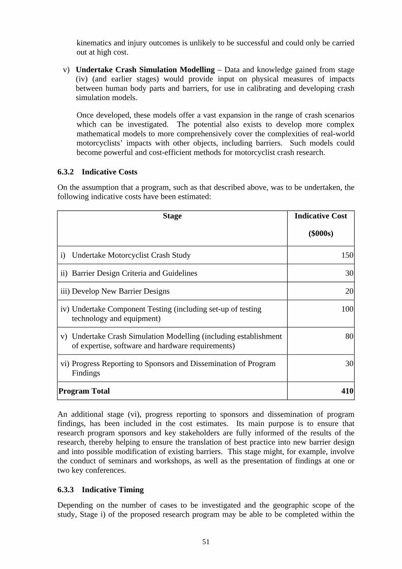
51
kinematics and injury outcomes is unlikely to be successful and could only be carriedout at high cost.
v) Undertake Crash Simulation Modelling – Data and knowledge gained from stage(iv) (and earlier stages) would provide input on physical measures of impactsbetween human body parts and barriers, for use in calibrating and developing crashsimulation models.
Once developed, these models offer a vast expansion in the range of crash scenarioswhich can be investigated. The potential also exists to develop more complexmathematical models to more comprehensively cover the complexities of real-worldmotorcyclists’ impacts with other objects, including barriers. Such models couldbecome powerful and cost-efficient methods for motorcyclist crash research.
6.3.2 Indicative Costs
On the assumption that a program, such as that described above, was to be undertaken, thefollowing indicative costs have been estimated:
Stage Indicative Cost
($000s)
i) Undertake Motorcyclist Crash Study 150
ii) Barrier Design Criteria and Guidelines 30
iii) Develop New Barrier Designs 20
iv) Undertake Component Testing (including set-up of testing technology and equipment)
100
v) Undertake Crash Simulation Modelling (including establishment of expertise, software and hardware requirements)
80
vi) Progress Reporting to Sponsors and Dissemination of Program Findings
30
Program Total 410
An additional stage (vi), progress reporting to sponsors and dissemination of programfindings, has been included in the cost estimates. Its main purpose is to ensure thatresearch program sponsors and key stakeholders are fully informed of the results of theresearch, thereby helping to ensure the translation of best practice into new barrier designand into possible modification of existing barriers. This stage might, for example, involvethe conduct of seminars and workshops, as well as the presentation of findings at one ortwo key conferences.
6.3.3 Indicative Timing
Depending on the number of cases to be investigated and the geographic scope of thestudy, Stage i) of the proposed research program may be able to be completed within the
52
period of 18 months to two years. Stages ii) and iii) could commence either after thecompletion of Stage i) or be done concurrently with Stage i). Thus, if Stages ii) and iii)commence after the completion of Stage i), it is estimated that Stages i) to iii) could becompleted within 2.5 to three years (this period could be shortened if Stages ii) and/or iii)commenced prior to the completion of Stage i)). Stages iv) and v) could be undertakenmore or less simultaneously, over a period of some 12 to 18 months. Stage vi) could occuras required throughout the life of the research program, however, most of the activityassociated with dissemination of program findings would logically occur following thecompletion of Stages i) to v).
In summary, the total program could be undertaken progressively over a period ofapproximately four to five years, at a cost of around $410,000, with reporting of programfindings occurring at appropriate intervals both during and after this four to five yearperiod. The estimates of costs and timing should be regarded as indicative only, andshould be subject to detailed development if further consideration of this research programis proposed.
6.3.4 Options for Sponsorship
The estimated cost of the project in present day dollars (year 2000) is around $410,000,with a proposed research program duration of some four to five years. Given thatmotorcyclist injuries due to impacts with roadside barriers are a relatively small, thoughhigh severity, proportion of the total road safety problem, it may be that individual states orterritories of Australia will be reluctant to expend funds of this magnitude. On thisassumption, and in order to ensure that high quality research and testing standards areachieved, it may be desirable to seek funding from a number of Australian jurisdictions toenable this program to be undertaken. A cooperative research program into which anumber of jurisdictions contribute funding has the unique advantage that all would receivethe full benefit of new knowledge gained in the area.
Given that this problem is also one of international concern, the possibilities of seekingfunding contributions from overseas agencies, especially European countries wheremotorcycling is very popular, might also be considered if insufficient funds were availablenationally. The notion of contributions from a number of Australian jurisdictions iscompatible with a proposed national in-depth study of motorcycle crashes (Stage i) above).Conducting such a study nationally will accelerate progress in collecting an adequatenumber of cases, as well as ensuring that state agencies with safety responsibilities in thisarea are actively involved and committed to the final outcomes of the research.
53
7 REFERENCES
ATSB, (2000). Review of Wire Rope Safety Barriers. ATSB Working Party Report, June,2000.
Baltic Construction Company (1999). ERAB 99-05.
Chinn, B. P., Okello, J. A., McDonough, P. J. & Grose, G. (1996). Development andtesting of a purpose built motorcycle airbag restraint system. Report, no.DOT HS 808465, 1167-88, United States. National Highway Traffic Safety Administration (NHTSA),Washington, DC, USA.
Corben, B., Gelb, K., Pronk, N. and Fitzharris, M. (1999). Motorcycle Safety - Stage 2.Contract Report prepared for VicRoads.
Cunningham, J. A. (1993). Roadside Hazard Management. Paper presented at MonashUniversity Workshop on Road Safety Audit. 14 – 16th April.
Czajka, M., (2000). Designing Roads for Motorcycle Safety. Unpublished Report.
Domhan, M. (1987). Guardrails and passive safety for motorcyclists. Vehicle highwayinfrastructure : safety compatibility. Warrendale, Pa.: Society of Automotive Engineers,pp. 205-208.
FEMA, (2000). Final Report of the Motorcyclists and Crash Barriers Project.http://www.nmcu.org/forskning/fema_cbp/index.html.
Gowan, R (VicRoads. Road Safety Department) (1996). Wire rope safety barrier -Frankston Freeway, part 2. Safe Roads, no.94.
Grösch, L. & Hochgeschwender, J. (1989). Experimental Simulation of Car/Pedestrianand Car/Cyclist Collisions and Application of Findings in Safety Features on the Vehicle.SAE International Congress and Exposition, Detroit, Michigan, February 27-March 3.
Harris, J. (1991). Proposals for test methods to evaluate pedestrian protection for cars.13th ESV Conf. Paris, France, Nov. 4-7, Paper no. S3-O-06.
Haworth, N., Smith, R., Brumen, I. & Pronk, N. (1997). Case-control study ofmotorcycle crashes. Monash University Accident Research Centre - Report No.174.
Ishikawa, H., Yamazaki, K., Ono, K. & Sasaki, A. (1991). Current situation of pedestrianaccidents and research into pedestrian protection in Japan. 13th ESV Conf. Paris, France,Nov. 4-7, Paper no. S3-O-05.
Janssen, E.G. (1996). EEVC Test methods to evaluate pedestrian protection afforded bypassengers cars. 15th ESV Conf., Melbourne, Australia, May 13-16, Paper no. 96-S7-W-17.
Koch, H. & Brendicke, R. (1989). Motorcycle accidents with guardrails. Road Safety inEurope, International Conference, 1988, Gotenburg, Sweden. VTI Rapport, no.343A,1989, 39-51, National Swedish Road and Traffic Research Institute, Linkoeping, Sweden.
54
Koch, H. & Schueler, F. (1987). Reduction of injury severity involving guardrails by theuse of additional W-beams, impact attenuators and ‘sigma-posts’ as a contribution to thepassive safety of motorcyclists. Eleventh International Technical Conference onExperimental Safety Vehicles, Washington DC, May 12-15, pp878-883.
Lupker H.A., de Coo P.J.A., Nieboer J.J., Wismans J. (1991). Advances in MADYMOCrash Simulations: SAE 910879, International Congress and Exposition, Detroit, February25-March 1.
MacLaughlin, T. F. & Kessler, J.W. (1990). Pedestrian head impact against the centralhood of motor vehicles – Test procedure and results. Procedings of the 34th STAPP CarCrash Conf., Orlando, Florida, Nov. 4-7.
Main Roads, Queensland (2000). Road Planning and Design Manual.
Newman J.A., Zellner J.W. Wiley K.D. (1991). A Motorcyclist Anthropometric TestDevice MATD. Proceedings of the 1991 International IRCOBI Conference on theBiomechanics of Impacts. Berlin.
Nieboer, J. J., Wismans, J., Versmissen, A. C. M. van Slagmaat, M. T. P., Kurawaki, I. &Ohara, N. (1993). Motorcycle crash test modelling. Stapp Car Crash Conference, 37th, SanAntonio, Texas, USA, pp. 273-288.
Ouellet, J. V. (1982). Environmental hazards in motorcycle accidents. AmericanAssociation for Automotive Medicine annual conference, 26th, October 4-6, Ottawa.Proceedings, pp. 117-129.
Pieribattesti, F, & Lescure, B. (1999). New safety barriers better adapted to the restraint ofmotorcyclists. Revue Generale des Routes, no.779, 20-2.
Sakurai M., Kobayashi, K., Ono, K. & Sasaki, A. (1994). Evaluation of pedestrianprotection test procedure in Japan – influence of upper body mass on leg impact test. 14th
ESV Conf., Munich, Germany, May 23-26, Paper no. 94-s7-o-01.
Sala, & Astori (1998). New concepts and materials for passive safety of motorcyclists.Proceedings of the IRCOBI Conference, September 1998, Göteborg.
Quincy, R., Vulin, D. & Mounier, B. (1988). Motorcycle impacts with guardrails.Transportation Research Circular, no.341, 23-35.
Schmidt, (1997). Brifen integral to motorway safety. Highway Engineering in Australia,29, Nov/Dec.
St. Laurent A., Shewchenko N., Szabo T. (1989). Development of frangible knee and hipelements for a motorcycle ATD (Summary). Biokinetics and Associated, LTD., Ottawa.
Van Driessche, H. (1994). Development of an ISO standard for motorcycle researchimpact test procedures. Proceedings of the 14th International Technical Conference on theEnhanced Safety of Vehicles. 23 – 26 May, Munich, Germany.
VicRoads (Road Safety Department). (1998). Flexfence Wire Rope Safety Rope SafetyBarrier. Safe Roads, no.105.

55
VicRoads (2000). Road Design Guidelines: Safety Barriers. March 2000.
Yettram, A. L., Happian-Smith, J., Mo, L. S. M. & Macaulay, M. A. (1994). Computersimulation of motorcycle crash tests. Proceedings of the 14th International TechnicalConference on the Enhanced Safety of Vehicles. 23 – 26 May, Munich, Germany.
Zellner, J. W., Wiley, K. D., Broen, N. L. & Newman, J. A. (1996). A standardizedmotorcyclist impact dummy for protective device research. Report, no.DOT HS 808 465,1756-81. United States. National Highway Traffic Safety Administration (NHTSA),Washington, DC, USA.