crash-barrier research and application in the …
TRANSCRIPT

CRASH-BARRIER RESEARCH AND APPLICATION IN THE NETHERLANDS H. G. Paar, Institute for Road Safety Research, Voorburg, The Netherlands
In the Netherlands the Institute for Road Safety Research carried out research into the most suitable crash barriers for soft soil and for bridges. Based on a number of requirements, the research resulted in a series of structures that provide optimum protection in soft soil and on bridges under various conditions. The barriers comprise in principle a horizontal beam consisting of 2 W-shaped rails and spacers every 1.33 m, provided if necessary with diagonal bars, and of posts with various structural characteristics. On this basis, the Netherlands authorities issued provisional guidelines for crash barriers in soft soil and on bridges on and over expressways. These are now being used generally on national highways.
•IN 1963, the Netherlands Minister of Transport decided that all expressways carrying 20,000 vehicles or more a day should be provided with median crash barriers because of the great increase in the number of vehicles crossing medians with fatal results. The barriers then built were similar to those in use in other countries (especially the United States and Germany).
Although accident statistics showed that the use of those barriers reduced the number of median crossings, there was often an increase in the number of recorded accidents involving casualties. The Institute for Road Safety Research was, therefore, asked to develop a crash barrier that would not have the apparent disadvantages of the customary ones. This research was commenced in 1964 and was provisionally completed in 1970 ( 1). The research was not limited to median barriers, but included shoulder barriers, the essential difference of which is that they can be hit from one side only. Meanwhile, Rijkswaterstaat, the agency that has authority over all national highways, has 1ssueo provisional guidelines, based on the results, for building crash barriers on expressways. Most local road authorities also follow those guidelines.
Even before the conclusion of the research into crash barriers in soft soil, a need arose to seek a solution for the specific problems of crash barriers on bridges. This led to separate research, which was commenced right after completion of the previous research and which, because of the experience already gained, was completed in 2 years. A report on these investigations is being prepared (2).
As there had already been very close contact with Rijkswaterstaat during the research, provisional guidelines for building crash barriers on bridges in and over expressways were completed almost parallel with the investigations. A summary of these guidelines and those for soft soil barriers is given in another report (~).
FUNCTIONAL REQUIREMENTS
Both investigations were based on a number of functional requirements. Each type of barrier was put to the test against these.
The first requirement is that the vehicle must not be able to enter the barrierprotected hazard area, such as an adjoining roadway, a steep embankment, or the edge of a bridge. Therefore, the vehicle must not break through the barrier, run under or over it, or topple over it. Although that requirement is very important, especially at the edges of bridges where the hazard risks are generally very great, it may nevertheless be varied somewhat, where risks are not so great, such as where there are wide medians or fairly flat obstacle-free shoulders.
40
41
Compliance with this first requirement, however, is not enough. Not only must a barrier stop vehicles that may go off the road, it must also really provide protection. Thus, the second requirement is that injury must be prevented to occupants of colliding cars and that damage to these cars must be as slight as possible. The decisive factors are the forces exerted by the barrier and the vehicle's consequent longitudinal and lateral decelerations. The extent of the permissible decelerations is still debatable. The provisional norms are those for cars whose occupants are not wearing seat belts. These originate in the United States and are lateral max 3 g, longitudinal max 5 g, and total max 5 g ( 4). Those figures, however, are definitely not final but depend on factors such as whether seat belts are worn and the internal construction of the vehicle. As changes occur in the years ahead, those norms may also change.
Besides protection of the car itself, the traffic the car leaves must not be exposed to any additional danger. Hence, a third requirement is that the car must not rebound into traffic flow and, if at all possible, should stop off the roadway.
In the case of heavy traffic densities, a barrier damaged by one impact may be hit again in the same place before repairs are made. The fourth requirement, therefore, is that the barrier should continue to be reasonably operational after being hit. The fifth and last requirement is that it must be possible to repair the barrier quickly after a collision with minimum inconvenience or danger to traffic.
STRUCTURAL REQUIREMENTS
To translate the functional requirements into the structural requirements that crash barriers must satisfy requires a consideration of the types of vehicles. In the Netherlands, road traffic consists mostly of private cars weighing 500 to 1,500 kgf, but there are also a considerable number of buses and lorries weighing as much as 50 tf. To prevent a vehicle that has run off the road from running into traffic, the barrier must have enough longitudinal strength to resist the forces that occur. During the investigations it was found that, if the barrier and the anchorings at the beginning and end can absorb 40 tf without breaking, even the heaviest impacts will not break the barrier in the normal course of events.
The requirement that no vehicles should push under the barrier or topple over it is difficult to meet in view of the big variety of vehicles. To eliminate the risk of vehicles toppling over requires that the forces between the barrier and the vehicle be applied above the center of gravity or close to it. That is impossible, however, for all vehicles. The barrier, therefore, has to be exactly high enough for normal private cars not to push under it, i.e., no more than about 45 cm above the road surface. A measure, which is then required to ensure that lorries do not topple over, is the flexibility of the barrier, which is also necessary for limiting vehicle decelerations. This flexibility limits the barrier's reactive forces on the vehicle and thereby reduces the danger of its toppling over. This means that the height of the barrier must remain about the same during deflection and that the wheels must not hit any upright edges, such as gutters or curbs, that could cause the vehicle to topple.
As stated, lateral decelerations can be kept low by the deflection of the barrier. In the case of extreme impacts on the 2-lane roads most common in the Netherlands (speed 100 km / h, impact angle 20 deg), at least 1-m deflection is necessary to obtain acceptable decelerations if the deflection is gradual. In view of Dutch traffic patterns, that applies to private cars, and deflection for lorries under the same conditions will be greater. If the deflection is kept within reasonable limits, the forces must increase progressively as the deflections proceed further.
Longitudinal decelerations can be kept low by ensuring that the impacting vehicle encounters no discontinuities in the barrier. The start of the barrier must be built so that there can be no head-on collisions with it or else that decelerations during any such impact remain within reasonable limits. Posts in the crash barrier must be impossible to hit or be constructed so that they give easily when hit.
To ensure that the vehicle does not rebound into the traffic flow requires that the exit angle be small and that the vehicle continue to travel almost parallel to the barrier. This can be achieved with very gradual barrier deflection. Research has shown that a
42
ratio of 1: 40 between the extent of the deflection and the length of the deflection wave gives very good results. In addition, the deflection must be due primarily to plastic deformation, for elastic deformation may cause severe rebounds.
So that a vehicle diverted and brought to a stop in this way is not a dangerous obstacle to other traffic, there should be a large enough recover area between the roadway and the crash barrier. Impacts are also fewer when barriers are not so close to the roadway. The recover area moreover makes it possible to repair the barrier with little inconvenience to traffic.
For easy maintenance and economy of installation, the various crash barriers, whether for soft soil or for bridges, should have as many standardized parts as possible.
STRUCTURAL DESIGN
The research was mainly experimental. For barriers in soft soil, more than 100 impact tests were made. They were carried out with private cars weighing between 500 and 2,000 kgf (impact angles 12, 15, and mostly 20 deg; speeds between 70 and 110 km/h) and with lorries and buses weighing between 3,500 and 10,000 kgf (impact angles 15 and mostly 20 deg; speeds between 50 and 80 km/h). For the bridge barriers, about 50 impact tests were made with the same vehicles under similar conditions. In addition, a mathematical model was devised for simulating impacts with the developed and similar structures.
The research related to a very wide variety of barriers. On the whole, the concrete barriers that then existed failed to meet all the requirements. Although most concrete barriers were practically impenetrable and suffered little damage, lorries still tended to overturn and decelerations and vehicle damage were too great to be acceptable. No effort was, therefore, made to develop a more suitable concrete barrier. Situations do occur, however, where no other barrier is possible, especially where there is very little space. Based on U.S. research ( 5), a concrete barrier, having the New Jersey barrier cross section, is still recommended under such conditions.
Cable barriers also failed to satisfy all the requirements. Decelerations were indeed slight, but the outcome of impacts was not always predictable, and there is thus no guarantee that cars will not break through them. In addition, such barriers were very badly damaged and ceased to operate. They have, therefore, been abandoned entirely.
The research ultimately showed that steel structures having normal W-shaped guide rails were the most satisfactory. Structures were made that had standardized parts and provided a solution in the most common circumstances. Figure 1 shows a number of possible structures in soft soil; Figure 2 shows a number of structures for bridges.
Of those structures, the flexible offset 2-rail barrier is most recommended. It has a 0.8-m-wide beam consisting of 2 normal W-shaped guide rails connected every 1.33 m by spacers, resting on posts every 4 m, the design of which depends on the barrier's location (soft soil or bridge surface). In both cases the post is made so that it allows the barrier to deflect fairly easily.
When collided with, this barrier functions as follows: The colliding vehicle first hits the top corrugation of the rail because it is slightly inclined (at an angle of 6 deg), initiating the desired movement of the barrier, · i.e., rotation around an imaginary pivot below or just at ground level. The barrier located in soft soil has a flattened post that cuts easily through the soil; a post on a bridge surface tears easily because it has a comparatively weak weld at the base. As the barrier bends, resistance to deflection gradually increases, among other things, because torsional forces build in the beam and longitudinal forces build in the 2 W-rails. This continues until the rail touches the ground at the side away from the impact. Measured horizontally at the front rail, the deflection is now about 1 m. This is approximately what happens when a private car weighing about 1,000 kgf hits the barrier at 100 km/h at an angle of 20 deg (Fig. 3).
With more severe impacts the play of forces on the barrier changes because the rear rail is forced against the ground. This greatly increases the resistance to deflection and causes the required 2-stage effect, whereby the deflection, which hwnan tolerance does not require to be greater, is kept within limits. When hit by heavy

43
trucks, however, the barrier may deflect as much as 2 m. During deflection the front (top) rail always stays at a height of at least 75 cm, preventing the colliding vehicle from overturning.
Extensive research was undertaken in connection with designing both soft-soil and bridge barriers ( the post is the only part that is materially different). For soft-soil barriers a post was sought that cuts easily through the soil when the barrier deflects and that greatly resists lateral bending. The ultimate solution was a 76-mm-diameter tube having a wall-thickness of 5 mm and the underground part of about lm flattened to 33 mm thick. Inasmuch as the soil structure very common in the Netherlands is rather loose, this post has little ground resistance when the barrier is deflected and the pivot is low. This is a major factor in achieving the required 1: 40 deflection; even with greater deflections, the posts remain almost completely under the barrier so that there is little danger of vehicles colliding with them. This eliminates the artificial pivot, in the form of a concrete sphere (4,p. 7) used earlier.
In addition, rupture bolts in the post-spacer joint ensure that the impact has no serious consequences in the way of extreme decelerations by the vehicle. Those bolts also ensure that the necessary flexibility, although it may not be ideal, continues to exist when the ground is frozen.
The bridge barrier post has the IPE 100 cross section. For the flexible barrier, only the body of the post is welded to the baseplate with a 3-mm rupture weld. This barrier, therefore, also gives easily and has the desired 1:40 deflection. The risk is greater of hitting the post of a bridge barrier than of a soft-soil barrier because the pivot is practically at road-surface level. Because of the weak rupture weld, however, the deceleration of a vehicle colliding with the post is slight. The spacer was based on German research that found it to be the most satisfactory ( 6). It is very rigid and has as a special feature an easily bending lip in the bottom corrugation of the rail. This ensures that the load on the bottom corrugation does not become excessive with great deflection. That is particularly effective when a lorry's wheel bolts cut into the rail.
Although it may seem illogical at first sight, the offset 2-rail barrier is also used where it can only be hit from one side, for instance on shoulders. As the foregoing has shown, the rear corrugated rail has a definite function in securing the necessary beam rigidity and in supporting the 2-stage effect.
The great deflection of the flexible barrier makes it impossible to use it where there is insufficient space. In such cases, a less flexible structure will have to be used. In the flexible barrier, the rigidity of the beam, the resistance of the posts, and the number of posts form a balanced unit that gives the required form of deflection. The barrier must, therefore, be stiffened very carefully.
For a bridge barrier, a diagonal bar is first placed in the beam in every third field formed by the rails and the spacer. That stiffens the beam so that more posts will deflect. If the post-to-post distance remains the same, the length of the deflection wave will then be greater than 40 times the deflection. More posts can now be used, reducing the length of the deflection and stiffening the structure as a whole. Possible postto-post distances are 2.67 and 1.33 m. For crash barriers in soft soil, a post-to-post distance of 2.67 m is first applied, after which diagonal bars are fixed; otherwise, the principle is the same.
If a barrier that has 1.33 m between posts still deflects too much for local conditions, various types of stabilizing plates can be used for soft-soil barriers to impede the post's movement. For crash barriers on bridges, the welding method can be adapted by welding not only the body but also the front flange (in barriers that can only be hit from one side) or all around (in barriers that can be hit from both sides). The welds can also be made thicker. The effect on deflection of the various stages of stiffening crash barriers in soft soil is shown in Figure 4. The curves are similar for crash barriers on bridges. In Figure 4, D = dynamic deflection of rear rail, and I = Gv /3.6 g sine i, where G = vehicle weight in kgf, v = vehicle speed in km/h, g = acceleration of gravity in m/sec 2
, and i = impact angle (20 deg in tests). Because there is no 2-stage effect with very stiff barriers, the spacing at the back can be omitted. This gives a saving of about 20 cm, but part of this is lost again because the beam is narrower and hence not so stiff.

44
Figure 1. Offset 2-rail barrier in soft soil.
' ' stabiliz ing ·,
plale ,
'
' I ! :
I /
I.__ • • •••. , dl•&onal bar
J· ·1F---JJ- -f
Figure 2. Offset 2-rail barrier on bridge.
Figure 3. Collision of 1, 150-kgf vehicle with soft-soil barrier at 100-km/h speed and 20-deg impact angle.
Figure 4. Deflection curves of offset 2-rail barriers in soft soil.
D(cm) f ..... - --200 F2w400
150 Sp2n267
100 Sbp2n267 Sbp2nl33
50 Sbp2n(C)!33
0 2000 4000 6000 l(kgl~

45
The flexible barriers obtained met all functional requirements best. The soft-soil barrier will suffer less damage from minor collisions than the bridge barrier because one or more posts of the latter will always have to be replaced. The stiffened barriers also satisfied most of the requirements, except that in comparable collisions the lateral decelerations especially will be greater because the barrier is stiffer. These decelerations are still so slight, however, that the occupants of a light private car can even survive a severe collision with a very stiff barrier (certainly if they are wearing safety belts; the maximum lateral deceleration will then be no more than about 7 g for some tenths of a second).
Proper operation of the barriers demands that there be no internal or external discontinuities. Transitions from flexible to stiffer barriers must be very gradual and nothing must prevent the barrier deflecting, for instance, rigid obstacles immediately behind it. Some discontinuities, however, are unavoidable. For instance,. some play has to be allowed at joints in bridges, and that adversely affects barrier operation. At the moment a solution appears to be fitting a hydraulic shock absorber parallel to the joint. A similar problem occurs on bridges with moving sections. A solution is being sought and is likely to be found.
Emergency vehicles, such as police cars and ambulances, should be able to cross the median easily at some points. That was solved by building a movable part in the barrier. Under normal conditions this guarantees a continuous barrier with practically the same characteristics as the normal barrier, but in emergencies it can easily be opened leaving a passage of about 4.70 m.
INST ALLING BARRIERS
Crash barriers are only justified if colliding with them is less dangerous than entering the protected hazard area. The decision process applied for expressways is shown in Figure 5. Medians ( without obstacles) wider than 12 m are not usually provided with barriers, nor are shoulders where there are no hazards within 10 m of the roadside. These figures are based on data gathered in the United States (7).
Based on the research results, provisional guidelines for expressways have been issued in the Netherlands, as stated above. On the one hand they give cross sections for new roads, allowing for the construction of crash barriers; on the other, they give solutions for (existing) situations where there is too little space for flexible barriers. It is in these particular cases that the standardization is such a great advantage. The recommended barriers and their location in the cross section, in soft soil and on bridges in new roads, are shown in Figures 6 to 12. All dimensions in the figures are in meters. The meaning of the codes is as follows:
Description
Flexible, no diagonal bars in beam, 2 offset rails, rupture device, post-to-post distance 4 m
Flexible, no diagonal bars in beam, 2 offset rails, posts only welded at body to baseplates, post-to-post distance 4 m
Stiff, diagonal bars added in beam and post-to-post distance reduced, 1 offset rail (2 W-rails), posts only welded at body to baseplates, post-to-post distance 1.33 m
Stiff, diagonal bars added in beam and post-to-post distance reduced, 1 offset rail ( 1 rail, 1 strip with same cross section), posts only welded at body to baseplates, post-to-post distance 1.33 m
Code
F2w400
F2B400
There must be no curbs or gutters in front of the posts with a difference in height greater than 0.05 to 0.07 m, either in soft soil or on bridges. In soft soil, the normal deflection of the posts must not be prevented by surface metal, gutters, or similar obstructions immediately behind the posts.

Figure 5. Decision model for use of crash barriers on expressways.
CRASH BARRIER YES/NO
RISKS FOR THIRD PARTIES
ENTRAL RESERVE
YES
INTERMEDIATE
SHOULDER
NO
MULTI-LEVEL
JUNCTIONS
RISKS FOR OCCUPANTS WITHIN 10 M
OBSTACLES
YE S
MULTI -LEVEL
JUNCTIONS
NO
OTHER EFFECTIVE MEASURES
~-----CRASH BARRIER
Figure 9. Barrier F2w400, with obstacles, in soft soil on shoulder.
3.15
3,00
Figure 12. Barrier Si,p 11 B133, with inspection path, on bridge on shoulder.
YES
NO CRASH BARRIER
Figure 10. Barrier S.,..1B33, without obstacles, on bridge in median.
0,51 3,oo 050 I Qoo
Figure 6. Barrier F2w400, without obstacles, in soft soil in median.
600
260 2,60
Figure 7. Barrier F2w400, with obstacles, in soft soil in median.
rr1T.d obstac le 040
1,50 0,80 1~0 1,10 0.00 1,50
7.20
Figure 8. Barrier F2w400, without obstacles, in soft soil on shoulder.
3,15 q:;00.8Q 1,70
3,00
Figure 11. Barrier Si,p1B133, with obstacles, on bridge in median.
5,20 +d ;( min.4,20 •d)
h
47
PRACTICAL EXPERIENCE
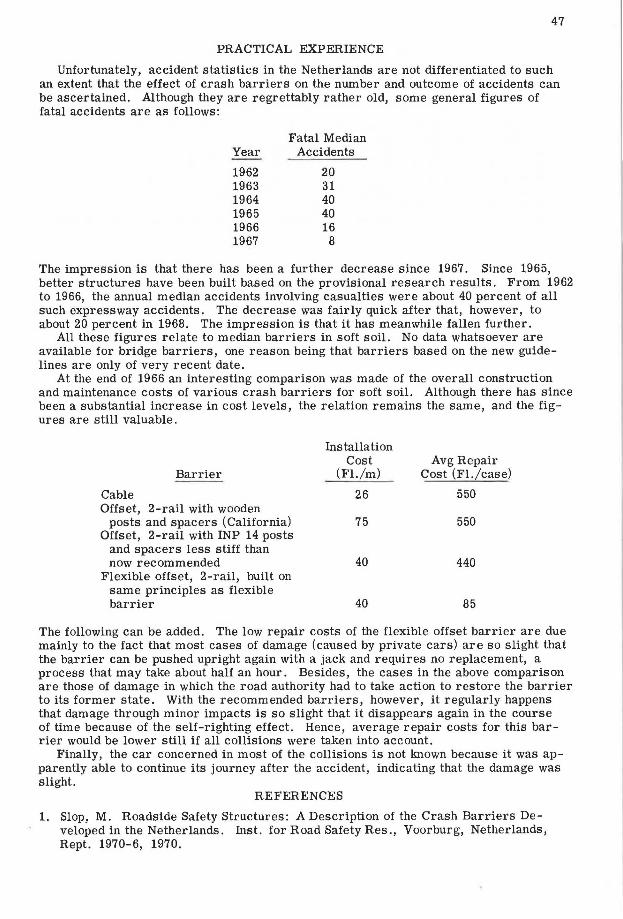
Unfortunately, accident statistics in the Netherlands are not differentiated to such an extent that the effect of crash barriers on the number and outcome of accidents can be ascertained. Although they are regrettably rather old, some general figures of fatal accidents are as follows:
Year
1962 1963 1964 1965 1966 1967
Fatal Median Accidents
20 31 40 40 16
8
The impression is that there has been a further decrease since 1967. Since 1965, better structures have been built based on the provisional research results. From 1962 to 1966, the annual median accidents involving casualties were about 40 percent of all such expressway accidents. The decrease was fairly quick after that, however, to about 20 percent in 1968. The impression is that it has meanwhile fallen further.
All these figures relate to median barriers in soft soil. No data whatsoever are available for bridge barriers, one reason being that barriers based on the new guidelines are only of very recent date.
At the end of 1966 an interesting comparison was made of the overall construction and maintenance costs of various crash barriers for soft soil. Although there has since been a substantial increase in cost levels, the relation remains the same, and the figures are still valuable.
Barrier
Cable Offset, 2-rail with wooden
posts and spacers (California) Offset, 2-rail with INP 14 posts
and spacers less stiff than now recommended
Flexible offset, 2-rail, built on same principles as flexible barrier
Installation Cost
(Fl./m)
26
75
40
40
Avg Repair Cost (FL/case)
550
550
440
85
The following can be added. The low repair costs of the flexible offset barrier are due mainly to the fact that most cases of damage (caused by private cars) are so slight that the barrier can be pushed upright again with a jack and requires no replacement, a process that may take about half an hour. Besides, the cases in the above comparison are those of damage in which the road authority had to take action to restore the barrier to its former state. With the recommended barriers, however, it regularly happens that damage through minor impacts is so slight that it disappears again in the course of time because of the self-righting effect. Hence, average repair costs for this barrier would be lower still if all collisions were taken into account.
Finally, the car concerned in most of the collisions is not known because it was apparently able to continue its journey after the accident, indicating that the damage was slight.
REFERENCES
1. Slop, M. Roadside Safety Structures: A Description of the Crash Barriers Developed in the Netherlands. Inst. for Road Safety Res., Voorburg, Netherlands, Rept. 1970-6, 1970.

48
2. Crash Barriers for Bridges. Inst. for Road Safety Res., Voorburg, Netherlands, in press.
3. Beukers, B., and Asmussen, E. Roadside Safety Structures: Research and Applications. Assn. Internat. Permanente des Congres de la Route, Paris, Rept. Quest. 4, The Road in Relation to Traffic Requirements, 14th World Congress, 1972.
4. Michie, J. D., Calcote, L. R., and Bronstad, M. E. Guardrail Performance and Design. NCHRP Rept. 115, 1972.
5. Michie, J. D., and Calcote, L. R. Location, Selection, and Maintenance of Highway Guardrails and Median Barriers. NCHRP Rept. 54, 1968.
6. Bohringer, A., Rosehmann, R., and Domhan, M. Anfahrversuche an Leitplanken. Innenministerium Baden-Wurttemberg, Stuttgart, 1969.
7. Stonex, K. A., and Skeels, P. C. Development of Crash R esearch Techniques at the General Motors Proving Ground. Highway Research R ecor d 4, 1963, pp. 32-49.