morpheus - analogue haven · | 3 1. introduction thanks for purchasing (or otherwise acquiring) the...
TRANSCRIPT

MORPHEUS Stereo Morphing Z-Plane Filter
Copyright 2017 Rossum Electro-Music LLCwww.rossum-electro.com
Operation Manualv1.1_010417
2 |
Contents
1. Introduction
2. Module Installation
3. Overview
4. How to Use This Manual
5. Basic Functionality
6. The Main Display
7. Managing Filters
8. Editing Filters
9. Filter Sequencer
10. Utilities
11. Factory Cubes
12. Specifications
13. From Dave’s Lab
14. Acknowledgements

| 3
1. Introduction
Thanks for purchasing (or otherwise acquiring) the Rossum Electro-Music Morpheus Stereo Morphing Z-Plane Filter.
This manual will give you the information you need to get the most out of Morpheus. However, the manual assumes you already have a basic understanding of synthesis and synthesizers. If you’re just starting out, there are a number of good reference and tutorial resources available to get you up to speed. One that we highly recommend is:
Power Tools for Synthesizer Programming (2nd Edition)By Jim AikinPublished by Hal LeonardHL00131064
SupportIn the unlikely event that you have a problem with your Morpheus, tell us about it here:
http://www.rossum-electro.com/support/support-request-form/
… and we’ll get you sorted out.
If you have any questions, comments, or just want to say “Hi!,” you can always get in touch here:
http://www.rossum-electro.com/about-2/contact-us/
… and we’ll get back to you.
Happy music making!
4 |
2. Installation
As you will have no doubt noticed, the rear of Morpheus is a circuit board with exposed parts and connections. When handling Morpheus, it’s best that you hold it by the edges of the front panel or circuit board. It’s not particularly easy to blow up, but why take chances?
More specifically, the biggest risk (to the extent that there’s a risk), is damage by static electricity. Particularly on dry, cold days (or if you’ve just shuffled across your shag carpet in fuzzy slippers), make a point of touching the metal panel first, before touching any other part of the module.
While all Rossum Electro-Music modules are protected against reverse polarity damage, both to your module and your system, care should still be taken to connect the power cable correctly. (For more detail on our unique protection method, check out Dave’s discussion of Circuit Protection in Chapter 13.)
Plug the included 16-pin connector into the header on the rear of the module such that the red stripe on the cable (the -12V side) is on the same end of the header as the “Red Stripe (-12V)” text on the PCB.
Morpheus requires, at most, 135mA of +12V and 25mA of -12V.
We have included both M3 and M2.5 (for vector rails) mounting screws. Use what fits your system.
If rack rash is of concern to you, use the included nylon washers when mounting Control Forge in your case.
Be Sure You Have the Latest FirmwareIf we’ve released an updated version of firmware after your module was shipped to your dealer, you should update to that latest version before proceeding.
To check:
> Press and hold the Edit Filter button until the Utilities screen appears. At the bottom of the screen you’ll see the current installed firmware version.
> On the web, go to the Downloads tab at www.rossum-electro.com/ products/morpheus/ and note the latest firmware version.
> If it’s the same as the version in your module, you’re good to go. If not, follow the instructions there to update your module.
| 5
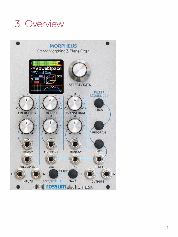
3. Overview

6 |
What is Morpheus?Morpheus is a unique digital filter module inspired by the 14th Order Z-Plane Filter Dave originally invented for E-mu’s fabled Morpheus synthesizer back in the mid-1990s. The Morpheus filter gives you the ability to create filters of a variety and complexity far beyond the capabilities of conventional synthesizer filters. Most excitingly, Morpheus lets you smoothly interpolate between up to 8 frequency response configurations in real- time, allowing you to explore an entirely new world of expressive, dynamic timbres.
The Morpheus module includes 289 meticulously crafted frequency response combinations, what we call “Cubes.”
Each Cube is composed of up to 8 complex frequency response configurations that you can picture as being at the corners of a three dimensional cube (hence the name). Morpheus gives you the ability to smoothly interpolate between those 8 configurations within the cube’s three dimensional space.
Due to processor limitations back in the day, the original Morpheus was capable of realtime morphing in one dimension, but interpolation in the frequency and transform dimensions were set at note-on and remained static for the remainder of the note. But even with that limitation, Morpheus offered sonic capabilities that are unmatched to this day.
With the Morpheus filter module, you now have simultaneous real-time CV control of all three dimensions, for dynamic timbral effects unlike anything you’ve ever heard before. In stereo.
Some DetailsA Morpheus Filter (i.e., what you select and load with the encoder and then use to process your audio) is actually the top level of a three level hierarchy. The three levels are:
A FREQUENCY RESPONSE: This is the most basic construct of a Morpheus filter. It is essentially a single static configuration of Morpheus’s 14 poles and zeros. For example, a frequency response might be configured as six independent bands of parametric EQ and a low pass section, as in Figure 1, above.
Even this basic building block is capable of creating filtering and resonant spaces of enormous complexity. But the real power comes from the ability to interpolate between multiple Frequency Responses.
A CUBE: A Cube provides the structure we need to control the interpolation between multiple Frequency Responses.
Let’s start with a simple example (actually simpler than any of the actual Cubes). Let’s imagine two different Frequency Responses and a single morph parameter to interpolate between them.
IN OUT
FC Q FC BW GAIN FC BW GAIN FC BW GAIN FC BW GAIN FC BW GAIN FC BW GAIN
1 Low PassSection
6 Parametric Equalizer Sections
FIGURE 1: A FREQUENCY RESPONSE
MORPH
FIGURE 2: A SIMPLE MORPH

| 7
By varying that single CV-controllable param-eter, you’re actually interpolating between 20 different frequency, bandwidth, resonance, and gain parameters simultaneously. We can visualize the result above, in Figure 3.
The next step would be to add another pair of Frequency Responses and control them with two parameters. That would look something like this:
Finally, by adding four more Frequency Responses, we have a full 3D Morpheus Cube, now controlled by three parameters, Frequency, Morph, and Transform.
FIGURE 3: VARYING A SINGLE CV-CONTROLLABLE PARAMETER
FREQUENCY
AM
PLI
TU
DE
MO
RPH
MO
RPH
A Filter
B Filter
FREQUENCY
MO
RPH
FIGURE 4: ADDING A PAIR OF FREQUENCY RESPONSES
In this case, the two parameters (Frequency and Morph) define a point on a virtual plane that specifies the interpolation between the four Frequency Responses. In Morpheus, configurations of this type are identified with a “.4” at the end of their Cube name.
In this case, you will be interpolating between all 8 component Frequency Responses, controlled by the position of the single interpolation point within the virtual 3D space. For ease of visualization, this is displayed (along with the resulting output frequency response) on Morpheus’s graphic display.
A MORPHEUS FILTER: Finally, at the top level of our hierarchy is the fully-configured Morpheus Filter. This consists of one of the 289 Cubes and the various parameters set in the Edit Filter Menu, described in Chapter 8.
FIGURE 5: 3D MORPHEUS CUBES ARE CONSTRUCTED OF 8 DIFFERENT COMPLEX FILTERS
FREQUENCY
TR
AN
SFO
RM
TR
AN
SFO
RM
TR
AN
SFO
RM
TR
AN
SFO
RM
FREQUENCY
FREQUENCY
MO
RPH
MO
RPH
MO
RPH
MO
RPH
FREQUENCY
8 |
A Few Words about DistortionAs described in Chapter 8, Morpheus is capable of producing a wide variety of unusual and distinctive types of distortion (depending on the character of individual cubes and the nature of the signals being processed). This is separate from the usually unwanted distortion produced by overdriving the input or by too high a gain through the filter.
All of the Morpheus Filters that are based on “.4” Cubes have the Transform control knob and CV input set to control distortion (since with only 4 Frequency Responses, there is no Transform axis to control anyway). However, even for the full 3D Cubes, you have the option of programming the Transform control and CV to control distortion, in which case the the actual Transform value is set as a static value by the Transform CV Offset parameter in the Edit Filter Menu. Again, see Chapter 8 for details.
In the following sections, we’ll look at each of Morpheus’s functions in turn.

| 9
Chapter 10: UtilitiesThis chapter describes various utility functions, including loading updated firmware, boot software, or new filter cubes, saving and reloading backups of all your filters and sequences, calibrating your Morpheus, and more.
Chapter 11: Factory CubesThis chapter describes each of Morpheus’s 289 Cubes. To help get you up and running quickly, we’ve provided preconfigured filters for each of the Cubes.
Chapter 12: SpecificationsYup, specifications.
Chapter 13: From Dave’s LabDave describes our unique approach to circuit protection.
Chapter 14: AcknowledgementsThanks to the talented folks who contributed in one way or another to the development of Morpheus.
4. How to Use This Manual
While, from a processing point of view, Morpheus is insanely complex, from a usability point of view, it’s actually pretty straightforward. Basically, pick a filter and modulate it to within an inch of its life. Beyond that, there’s creating your own custom filters using the Edit Filter menu, stringing filters together in series using the Filter Sequencer, and managing the housekeeping functions in the Utilities Menu.
With that in mind, the following chapters guide you through the above functions in order.
Chapter 5: Basic FunctionalityThis chapter introduces you to Morpheus’s basic functional principles, including basic operation, inputs and outputs, setting parameters, and loading and saving filters.
Chapter 6: The Main DisplayThis chapter describes the elements of Morpheus’s main operational display.
Chapter 7: Managing FiltersThis chapter describes saving and loading your Morpheus filters.
Chapter 8: Editing FiltersThis chapter describes editing the various parameters that define a Morpheus filter.
Chapter 9: Filter SequencerThis chapter covers the functionality of the Filter Sequencer, which allows you to program sequences of filters and navigate through the sequences with the encoder or under the control of triggers from other modules in your system.

10 |
5. Basic Functionality
IMPORTANT: While the left and right channels are completely independent,
they are both processed by the same filter (although individual Gain and Distortion parameters can be selected for each channel). With that limitation, you can, should you desire, choose to input completely different audio into the two channels.
Freq CVThis is a control voltage input that is modified by its associated attenuverter and then summed with the values of the Frequency knob and the Full Level CV input to produce the final Frequency control value.
Before we jump into individual functions, let’s take a look at Morpheus’s basic organization.
Power UpWhen power is applied to the module for the first time, it begins with Filter 001 as the Current Filter and the Filter Sequencer OFF.
On subsequent power ups, the Filter and Sequence that were current at power off are restored.
FiltersFilters can be selected and loaded using the Data Encoder as described in Chapter 7 or by the Filter Sequencer as described in Chapter 9.
Custom filters can be created and existing filters can be edited using the Edit Filter function. Custom and edited filters can be saved using the Save Filter function.
InputsAudio In Left/RightHere’s where you input in the audio to be processed by Morpheus. These are
true stereo inputs, as the channels’ separation is preserved through the processing chain to the outputs.
The Inputs expect a signal level up to 20Vp-p.
Morpheus is DC coupled throughout, so, with most cubes, you can use it to process CVs as well as audio.
Full LevelThis is an unattenuated CV input that is summed with the values of the Frequency knob and the
Freq CV input to produce the final Frequency control value.
Morph CVThis is a control voltage input that is modified by its associated attenuverter and then summed with the value of the Morph knob to produce the final Morph control value.

| 11
Trans CVThis is a control voltage input that is modified by its associated attenuverter and then summed with the value of the Transform knob to produce the final Transform, or optionally, the final Distortion control value.
NOTE: The function of this CV input (along with the Transform knob) for each filter
is set in the Edit Filter Menu. If Transform Controls Distortion is selected for a particular filter, then Transform is set to a static value and the knob and CV controls the amount of distortion produced by the current filter.
Sequencer Dec, Inc, and Reset
Depending on the Filter Sequencer state, rising edges at these inputs control the loading of a sequence’s programmed filter’s or navigation commands. These inputs accept digital signals with a threshold voltage of 1.65V. See Chapter 9 for details.
OutputsAudio Out Left/RightHere’s where the processed sound comes out.
Depending on the input levels, the settings of the various parameters, and the function of the selected filter, the outputs provide signal levels of up to 20Vp-p without clipping.
ControlsData EncoderThe Encoder is used to select and load Filters and Sequences as well as set the value of various parameters.
The Encoder includes an integrated pushbutton that is typically used to load the currently selected Filter or Sequence or to enter a currently selected parameter value (see individual parameters for details).
Frequency, Morph, and Transform Knobs
Each of these knobs lets you manually set a control voltage for its respective axis. The selected values are summed with their respective CV inputs to provide the final value for its axis.
Their range, as indicated on the panel, is from -5V to +5V. If no offset is set for an axis, its knob can potentially place the interpolation point at any location on the axis.
NOTE: A knob’s actual range of placement will be modified by any programmed
offset of its axis as well as any current control voltage.
Adjustment of these knobs (as well as any CVs present) is indicated in real time on the display by both the graphical CV indicators and the position of the interpolation point in the 3D Cube graphic.

12 |
Frequency, Morph, and Transform Attenuverters
These controls modify any CVs present at their respective inputs.
When an attenuverter knob is set to its “0” position, no control voltage at its input is passed to its associated axis.
As the knob is turned clockwise from 0, the amplitude of the control voltage increases until, at maximum clockwise rotation, the full amplitude of the signal at the input is passed through.
As the knob is turned counter-clockwise from 0, the signal at the CV Input is inverted (e.g., a CV of +2.5V becomes -2.5V). The farther counterclockwise the knob is turned, the less the attenuation of the inverted signal, until, at maximum counter-clockwise rotation, the full amplitude of the inverse of the signal at the input is passed through.
Edit Filter/Utilities ButtonPressing this button gives you access to the parameters that allow you to
create yourown custom filters. Details are in Chapter 8.
Pressing and holding this button brings up the Utilities Menu, where you will have access to Morpheus’s various housekeeping and maintenance functions. See Chapter 10 for details.
Save Filter ButtonPressing this button allows you to save new custom filters or filter edits. Details are in Chapter 7.
Load Sequence ButtonPressing this button allows you to select a previously saved Filter Sequence or to turn the sequencer on or off. Details are in Chapter 9.
Program Sequence ButtonPressing this button allows you to program or edit the steps of a Filter Sequence. Details are in Chapter 9.
Save Sequence ButtonPressing this button allows you to save new sequences or sequence edits. Details are in Chapter 9.
Setting ParametersApart from the axis CVs set by the front panel knobs, parameters are set by accessing the appropriate menu (Edit Filter, Program Sequence, or Utilities), using the encoder to select the desired parameter, pressing the encoder switch to display the parameter’s current value, using the Encoder to set the desired value, and then pressing the encoder switch again to accept the new value.
IMPORTANT NOTE: Whenever there are any unsaved parameter changes in a preset or
sequence, a red warning (P for Preset and S for Sequence) will appear in main display. If you select a new preset or sequence before saving them, the changes will be lost.

| 13
6. Main Display
meter extend into the red, you will need to lower the level of the input signal before it reaches the filter, by either adjusting the the level at the signal source or patching it through an attenuator, VCA, or mixer.
> The middle horizontal bar indicates the amount of distortion that results from the distortion settings in the Edit Filter menu. Red indicates distortion. See Chapter 8 for details.
> The bottom horizontal bar indicates the output level through the filter. If you are seeing this gain meter extend into the red, you will need to adjust the Left or Right Gain settings in the Edit Filter menu. See Chapter 8 for details.
The number and name of the currently loaded filter.
The number and name of the currently loaded sequence. If the Sequencer has been turned off, the display, rather predictably, is “Sequencer Off.”
Three horizontal graphical indicators of the real-time values of the Frequency (F), Morph (M), and Transform or Distortion (T or D) inputs to the filter. If a filter is set to control the Transform axis, The bottom indicator is labeled “T.” If a filter is set to Transform Controls Distortion, the indicator is labeled “D.”
NOTE: The graphic indicators display the values that are the sum of the manual
settings of the Frequency, Morph, and Transform knobs and any CVs appearing at their associated inputs.
ANOTHER NOTE: These graphical CV indicators always show the cumulative
CVs before any scaling. The 3D Cube Graphic will show the resulting position of the interpolation point after all scaling.
Morpheus’s main display provides a variety of information that gives you a comprehensive view of what’s happening in the module. Additionally, there are dedicated displays for loading and saving filters and sequences, programming and editing filters and sequences, and executing utility functions.
In this chapter, we’ll describe the main display. The rest will be described in their own chapters.
IMPORTANT: OLED displays (which is what the Morpheus display is) have long
lifetimes under normal use, but if you leave your system on 24/7 (or just want to ensure the longest possible life for your display), Morpheus provides the ability to adjust the brightness of the display (which is also useful for optimizing it for the ambient lighting level of your work environment) and, optionally, to set a time after which the display enters a screensaver mode. Both of these can help extend the life of your display. They are set in the Utilities menu. Details for setting them will be found in Chapter 10.
The main display provides the following:
The left and right VU and Distortion Meters. For each of the two audio channels:
> The top horizontal bar indicates the channel’s input level. As the level increases towards the right, the color of the bar transitions from green to yellow to red, so you can see at a glance how close to clipping the signal is. If you are seeing this

14 |
A Cube Graphic that illustrates the 3D parameter space of the currently selected filter cube. A colored dot within the cube indicates the real-time position of the interpolation point as defined by the values of the three individual parameter axes.
A Sequencer Status indicator which displays the current sequence step number
(if the step contains a filter) or an indication that the sequence is in a Halt (-H-) or Pause (-P-) state. Anytime that Morpheus receives a rising edge at the Sequencer Dec, Inc, or Reset inputs, the display briefly flashes yellow.
The current fade time scale factor. This only appears if the Sequencer is On, and the sequence has advanced to a step that contains a Fade Time Scale command.
NOTE: If Sequence Off has been selected, the sequence status displays described above are blank.
Red indicators that light when the current filter (F) and/or the current sequence (S) have unsaved changes.
A real-time animated plot of the current frequency response of the filter.

| 15
7. Managing Filters
Loading FiltersWhen the Filter Sequencer is Off, turning the encoder will bring up the Load Filter box and scroll through all existing filters. When you see the one
you want, click the encoder’s switch. The selected filter will be loaded, respecting the Exit Fade Time of the previously loaded filter and the Enter Fade Time of the the newly selected filter.
If you change your mind before clicking, scroll back to the currently loaded filter. You’ll see the Load Filter box disappear.
If you press and hold the encoder switch and then turn the encoder, each filter will load immediately as it appears in the Load Filter box (still respecting the fade out and fade in times).
When the Filter Sequencer is On, turning the encoder will only display and select filters in the currently loaded sequence. Sequence commands
(Pause, Halt, Bumper, etc) will be skipped over with no effect.
A TIP: This is not only useful for manually controlling Filter Sequences, but also lets
you use the sequencer to create sub-sets of filters for easy access in specific situations. For example, if you’re participating in a live performance with four different pieces, you can create a separate sequence for each of the pieces and program each one with only the filters you use in that piece. That way, during each piece, you’ll have quick access to the filters you’ll need, without having to scroll past lots of filters that you don’t need.
NOTE: As shipped from the factory, Morpheus contains a series of sequences
that subdivide the filters by basic function. Loading one of those sequences allows you to select among only that filter type.
Saving FiltersPress the Save Filter button to bring up the Save Filter display. The current filter is initially displayed.
Selecting a LocationWhen first
entering this screen, the encoder controls the Filter Number field. Scroll through the numbers to select a destination location (or don’t scroll to resave to the current filter’s existing location). Note that this scrolling does include --empty-- filter locations. At the top of the scrolling list is a special item, **ERASE**.
16 |
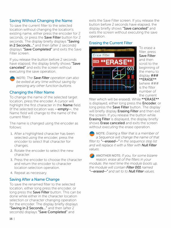
Saving Without Changing the NameTo save the current filter to the selected location without changing the location’s existing name, either press the encoder for 2 seconds, or press the Save Filter button for 2 seconds. The display briefly displays “Saving in 2 Seconds…” and then (after 2 seconds) displays “Save Completed” and exits the Save Filter screen.
If you release the button before 2 seconds have elapsed, the display briefly shows “Save canceled” and exits the screen without executing the save operation.
NOTE: The Save Filter operation can also be exited at any time without saving by pressing any other function buttons.
Changing the Filter NameTo change the name of the selected target location, press the encoder. A cursor will highlight the first character in the Name field. (If the selected location was --empty--, the Name field will change to the name of the current filter.)
The name is changed using the encoder as follows:
1. After a highlighted character has been selected using the encoder, press the encoder to select that character for changes.
2. Rotate the encoder to select the new character.
3. Press the encoder to choose the character and return the encoder to character location selection operation.
4. Repeat as necessary.
Saving After a Name ChangeTo save the renamed filter to the selected location, either long press the encoder, or long press the Save Filter button. This can be done while either in the character location selection or character changing operation for the encoder. The display briefly displays “Saving in 2 Seconds…” and then (after 2 seconds) displays “Save Completed” and
exits the Save Filter screen. If you release the button before 2 seconds have elapsed, the display briefly shows “Save canceled” and exits the screen without executing the save operation.
Erasing the Current FilterTo erase a filter, press Save Filter and then scroll to the beginning of the menu to display ### **ERASE** (where ### is the filter number of the current
filter which will be erased). While **ERASE** is displayed, either long press the Encoder, or long press the Save Filter button. The display will briefly display Erasing Filter and then exit the screen. If you release the button while Erasing Filter is displayed, the display briefly shows Erase canceled and exits the screen without executing the erase operation.
NOTE: Erasing a filter that is a member of a Sequence will change the name of that
filter to “--erased--” in the sequence step list and will replace it with a filter with Null Filter values.
ANOTHER NOTE: If you, for some bizarre reason, erase all of the filters in your
module, the next time the module boots up, the module will contain Filter 001 named “--erased--” and set to to Null Filter values.

| 17
8. Editing Filters
The Edit Filter menu is where you can create your own custom filters by selecting from among Morpheus’s 289 Cubes and setting your desired filter parameters.
To access the Edit Filter menu, press the Edit button.
Here are the available parameters:
Select CubeIf you are creating a new filter from scratch, here is where you will select which of Morpheus’s 289 Cubes the filter will use. If you
are only editing the parameters of an existing filter (gains, offsets, etc.), you’ll typically leave this alone.
NOTE: A special case is Cube 000, the Null Cube. The Null Cube provides no
processing, so you can think of it as a bypass of sorts. One reason to program a filter with the Null Cube is to use it in Filter Sequences for any steps where you want your audio to temporarily pass though unfiltered.
Frequency, Morph, and Transform CV OffsetsThe Frequency, Morph, and Transform CV Offsets let you define the interpolation
point on each respective axis that results from a cumulative CV of 0V (i.e., manual knob + CV input(s)) for that axis.
Their range is from -5.0V to +5.0V. The default value for all axes is 0.0V.
To set parameters:
1. Turn the encoder to scroll through the available parameter list.
2. Click the encoder to choose the desired parameter.
3. Turn the encoder to set your desired value.
4. Click the encoder to return the parameter list.
The menu is dismissed by pressing the Edit Filter button again.
18 |
THE DETAILS: With a CV Offset of 0.0V (i.e., no offset), a cumulative CV of 0V results in the interpolation point being in the exact center of its axis. In this case, a CV of +5.0V will place the point at one extreme end of the axis, while a CV of -5.0V will place it at the opposite extreme.
But if, for example, you set an offset of +2.0V, when you have a CV of 0V, the interpolation point will be 2/5 of the way from the center of the axis towards one end of the axis. In this case, it only takes a CV of +3.0V to move the point to the extreme end.
A CV of -2.0V will place the point exactly in the center of the axis, and it will take -7.0V to move the point to the opposite end of the axis.
NOTE: With no CV Offset, the Frequency, Morph, and Transform knobs can place
the interpolation points for their axes anywhere within the 3D Cube space without the need for any additional CV. However, when any CV Offset is programmed, the knobs can no longer cover the entire range by themselves. In that case, additional CV input is required to cover the entire range.
ANOTHER NOTE: The interpolation point can never extend beyond the edge of
the 3D Cube space. In the example above, once a CV of 3.0V has moved the point to the extreme end of its axis, any additional CV over 3.0V will have no effect.
YET ANOTHER NOTE: When Transform Controls Distortion is selected for a
particular filter, The Transform CV Offset parameter defines the static position of the Transform axis.
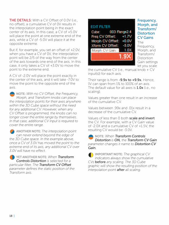
Frequency, Morph, and Transform/Distortion CV GainsThe Frequency, Morph, and Transform/Distortion Gain settings let you scale
the cumulative CV (i.e., manual knob + CV input(s)) for each axis.
Their range is from -9.9x to +9.9x. Hence, 1V can span from 1% to 100% of an axis. The default value for all axes is 1.0x (i.e., no scaling).
Values greater than one result in an increase of the cumulative CV.
Values between .99x and .01x result in a decrease of the cumulative CV.
Values of less than 0 both scale and invert the CV. For example, with a CV Gain value of -2.0X and a cumulative CV of +1.5V, the resulting CV would be -3.0V.
NOTE: When Transform Controls Distortion is ON, the Transform CV Gain
parameter changes it name to Distortion CV Gain.
IMPORTANT NOTE: The graphical CV indicators always show the cumulative
CVs before any scaling. The 3D Cube graphic will show the resulting position of the interpolation point after all scaling.

| 19
Enter Fade Time and Exit Fade TimeWhen transitioning from one filter to another, either manually by using the encoder or
via the Filter Sequencer, you can program independent Enter Fade Times and Exit Fade Times for each filter. The total transition time for any filter change will be the sum of the Exit Fade Time for the outgoing filter plus the Enter Fade Time for the new filter.
NOTE: The Fade Times programmed here can be scaled up or down (i.e., to be faster
or slower) when a filter appears in the Filter Sequencer. See Chapter 9 for details.
Left and Right GainThese parameters let you set the gain from input to output of each filter channel (Left or Right). The resulting
output gains are displayed on their respective channel output meters on the main display. If you see the output meters in the red (and you don’t like the resulting sound), you can reduce the gain here to bring the levels down below clipping.
Their range is -40dB to +40db in 1dB intervals. The default value for both channels is 0dB.
NOTE: These parameters only affect the gain through the filter. If you are seeing
the input gain meters extend into the red, you will need to lower the level of the input signal before it reaches the filter, by either adjusting the level at the signal source or patching it through an attenuator, VCA, or mixer.
Left and Right DistortionMorpheus is capable of producing a wide variety of unusual and distinctive types of distortion (depending
on the character of individual cubes and the nature of the signals being processed). These parameters set the amount of internal filter distortion for each channel (Left or Right). The range is from -30dB to +70dB.
The resulting amounts of distortion for each channel are displayed on their respective distortion meters on the main display (red indicates distortion). However, the most productive way of adjusting these parameters is by ear, i.e., just vary the values until you get the sound you want.
NOTE: If Transform Controls Distortion is OFF, these parameters set the static
amounts of filter distortion. If Transform Controls Distortion is ON, these controls set the amounts of distortion with no CVs present. CVs from the Transform Knob or Transform CV Input will further modify the distortion amount from that initial setting.

20 |
ANOTHER NOTE: It’s important to remember that the filter distortion set by
these parameters is intended to be a creative tool and is separate from the distortion that results from a too hot input to the filter or the distortion resulting from too high a setting of the Left and Right Gain parameters described above. Those are the kinds of distortion you typically don’t want (although maybe you do — it’s always your choice).
Transform Controls DistortionThe Transform Controls Distortion function lets you choose whether the Transform control, CV
input, and Gain setting affect the Transform axis interpolation point or the amount of filter distortion.
When this parameter is OFF:
> The Transform Knob and the Transform CV Input, in combination with the Transform Gain and CV Offset, control the interpolation point on the Transform Axis.
> The Left and Right Distortion parameters set the static amount of distortion for their respective channels.
When this parameter is ON:
> The Left and Right Distortion parameters set the initial amount of distortion for their respective channels.
> The Transform Knob and the Transform CV Input, in combination with the Distortion Gain parameter provide real-time control of the amount of distortion.
> The Transform CV Offset sets the static position of the interpolation point on the Transform Axis.
NOTE: When Transform Controls Distortion is ON, the Transform CV Gain
parameter in the Edit Filter menu changes its name to Distortion CV Gain.
ANOTHER NOTE: By default, all factory filters that end in “.4” are set to Transform
Controls Distortion. Since these filters consist of only 4 frequency configurations, controlling the Transform axis would have no audible effect.

| 21
9. Filter Sequencer
The Filter Sequencer allows you to create an ordered list of filters (and optionally, some navigational commands and commands that scale the individual filters’ fade in and fade out times) and then step through them under trigger control or manually via the encoder.
Sequence StructureA Filter Sequence is made up of a list of steps containing one or more filters, and, optionally, one or more commands that affect the progress of the sequence or the filters’ fade in and fade out times.
Sequences are numbered from 000 to 200. Sequence 000 is the special case “Off.” Sequences 001-200 each have a name of up to 12 characters. The default name of a sequence location that has never been saved to is “--empty--”.
The progress of the Filter Sequencer is controlled by triggers at the Dec, Inc, and Reset input jacks, as described below, as well as by the data encoder.
Load SequencePress the Load Sequence button to bring up the Load Sequence box. Use the encoder to scroll through
all of the existing sequences, displaying the number and name of each one. Empty or erased sequences are not displayed.
Press the encoder switch to select the desired sequence and load it into Morpheus and exit the Load Sequence screen.
NOTE: A long press of the Load Sequence button will also load the sequence displayed in the Load Sequence box. This
makes reloading the current sequence to easily and deliberately erase unwanted edits simply a matter of pressing Load Sequence, and then immediately long pressing it.
Sequence 000 (Off) turns off the sequencer. When Sequence 000 is loaded, triggers at the sequence control jacks are ignored.
When loaded, a sequence (other than Sequencer Off) begins at Step 001 and immediately loads the associated filter for that step.
NOTE: In addition to turning the sequencer off by selecting Sequence 000, pressing
and briefly holding the Load Sequence button will toggle the sequencer on and off without having to bring up the Load Sequence box.
Program SequencePressing the Program Sequence button brings up the Program Sequence screen and allows the selection or
editing of the filters and commands of the currently active sequence.
While in the Program Sequence screen, the display will show up to seven sequence steps (fewer if the sequence contains less than seven steps) and their current content.
To program or edit a step, use the encoder to scroll to that step (it will be displayed at a larger size than the unselected steps) and

22 |
press the encoder. The current content of the step will be highlighted in red and turning the encoder will select the desired content or action for that step.
Possible step contents include:
> Any existing filter
> A navigational command:
PauseHaltBumper
> A Fade Time Scale command
These commands will be described below. In addition, once a step is selected, you can perform the following Actions:
Insert Step: A new step containing a Pause is created and inserted at the current step number. It becomes the current step and is selected for editing.
Delete Step: The current step of the sequence is deleted, and you are returned to the Program Sequence screen.
Pressing the encoder while an action is highlighted executes that action. Pressing the encoder while a command or filter is highlighted replaces the current step contents with that command or filter.
Adding Steps to a SequenceTo add one or more steps to your sequence, scroll to end of the step list until Add a Step is highlighted. Press the encoder to add a step to the end of the sequence. Repeat as needed.
Sequence CommandsNOTE: The commands described below affect the flow of a sequence when it
is being clocked by triggers at the Inc, Dec, or Reset jacks. When navigating through a sequence using the Data Encoder, the Navigation Commands are ignored. I.e., you can use the encoder to directly load any filter in the sequence, regardless of surrounding nav commands.
Navigational CommandsThe Navigational Commands give you some additional ways to control the flow of your sequences. Here’s how they work:
When a new sequence is loaded, it begins at Step 001. Subsequently, any Reset rising edge acts to jump to Step 001 and load the filter or command associated with it, and any Inc or Dec rising edge will cause the sequence to move (circularly) to the next or previous step. If that step is a filter, it will be immediately loaded; if that step is a command, it will take effect per the descriptions below:
Halt: When a Halt Command is loaded, the sequencer enters the Sequence Halt state. In this state, subsequent Inc or Dec rising edges are ignored. Only a Reset rising edge (or the loading of a new sequence) will return the Sequencer to the normal state. A Reset rising edge also acts to jump to Step 001.
Pause: When a Pause Command is loaded, the sequencer enters the Sequence Pause state. In this state, subsequent Inc or Dec rising edges are ignored until receipt of a Reset rising edge, which will return it to the normal state. At that point, the Pause has been satisfied, and subsequent Inc or Dec signals act normally, and any Reset rising edge acts to jump to Step 001.
Bumper: When the sequencer is adjacent to a step containing a Bumper Command, the sequencer remains in a normal state, but ignores any Inc or Dec signals that would advance it to the Bumper step. Essentially, the sequence sticks at the step adjacent to the Bumper step until an Inc or Dec rising edge moves it away from the Bumper step, or until a Reset rising edge returns it to Step 001.
NOTE: Since sequences can progress circularly, it’s possible to encounter commands from either side.
| 23
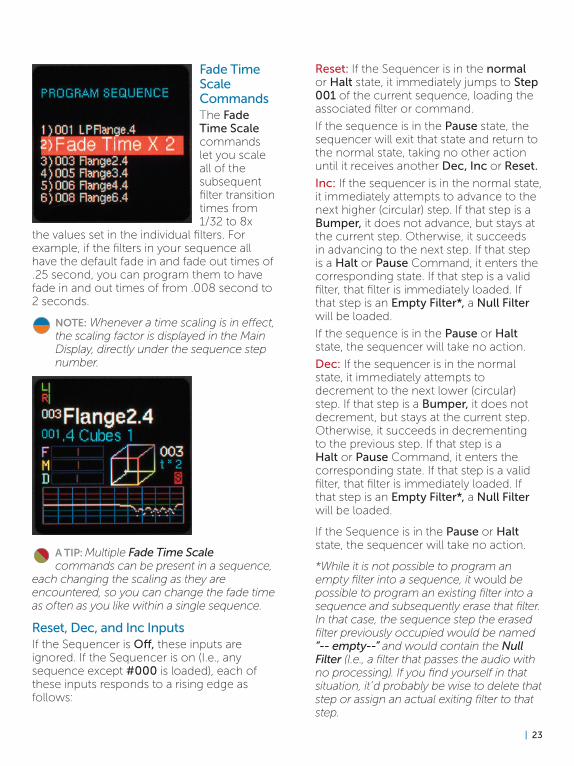
Fade Time Scale CommandsThe Fade Time Scale commands let you scale all of the subsequent filter transition times from 1/32 to 8x
the values set in the individual filters. For example, if the filters in your sequence all have the default fade in and fade out times of .25 second, you can program them to have fade in and out times of from .008 second to 2 seconds.
NOTE: Whenever a time scaling is in effect, the scaling factor is displayed in the Main Display, directly under the sequence step number.
Reset: If the Sequencer is in the normal or Halt state, it immediately jumps to Step 001 of the current sequence, loading the associated filter or command.
If the sequence is in the Pause state, the sequencer will exit that state and return to the normal state, taking no other action until it receives another Dec, Inc or Reset.
Inc: If the sequencer is in the normal state, it immediately attempts to advance to the next higher (circular) step. If that step is a Bumper, it does not advance, but stays at the current step. Otherwise, it succeeds in advancing to the next step. If that step is a Halt or Pause Command, it enters the corresponding state. If that step is a valid filter, that filter is immediately loaded. If that step is an Empty Filter*, a Null Filter will be loaded.
If the sequence is in the Pause or Halt state, the sequencer will take no action.
Dec: If the sequencer is in the normal state, it immediately attempts to decrement to the next lower (circular) step. If that step is a Bumper, it does not decrement, but stays at the current step. Otherwise, it succeeds in decrementing to the previous step. If that step is a Halt or Pause Command, it enters the corresponding state. If that step is a valid filter, that filter is immediately loaded. If that step is an Empty Filter*, a Null Filter will be loaded.
If the Sequence is in the Pause or Halt state, the sequencer will take no action.
*While it is not possible to program an empty filter into a sequence, it would be possible to program an existing filter into a sequence and subsequently erase that filter. In that case, the sequence step the erased filter previously occupied would be named “-- empty--” and would contain the Null Filter (I.e., a filter that passes the audio with no processing). If you find yourself in that situation, it’d probably be wise to delete that step or assign an actual exiting filter to that step.
A TIP: Multiple Fade Time Scale commands can be present in a sequence,
each changing the scaling as they are encountered, so you can change the fade time as often as you like within a single sequence.
Reset, Dec, and Inc InputsIf the Sequencer is Off, these inputs are ignored. If the Sequencer is on (I.e., any sequence except #000 is loaded), each of these inputs responds to a rising edge as follows:

24 |
Other Stuff to Know About Sequences > In addition to being off because you’ve
selected Sequence OFF, the sequencer is also off when you are in the Edit Filter menu (so it won’t be changing filters on you while you’re trying to program one) and while a filter is being saved. If the sequencer is Off due to editing or saving a filter, once those modes are exited, the sequencer will resume its previous state.
> Logically, all sequences loop at their end. Any step can be any entry (i.e., any filter or command) with the recognition that some entries or combinations make little functional sense or can even create completely dysfunctional sequences. Specifically, placing a Halt at Step 001 will result in a sequence that can never progress beyond Step 001 (except through the use of the encoder).
> Special case: A Bumper placed at Step 001 acts as a (satisfied) Pause (i.e., an Inc or Dec will move to adjacent steps).
Save SequenceSaving Sequences (including naming them) functions exactly like saving Filters as described in Chapter 7. Rather than
duplicate all that here, refer to that chapter and, in your mind, replace “Filter” with “Sequence.”
| 25
10. Utilities
The Utilities menu is where you’ll find Morpheus’s various housekeeping and maintenance functions.
To access the Utilities menu, press and hold the Edit Filter button. Turn the encoder to scroll through the available function list. Click the encoder to choose the desired function.
The menu is dismissed by pressing the Edit Filter button again.
While in any Utility function, filtering is disabled; no signal passes from the audio inputs to the audio outputs. When a Utility function is exited, Morpheus resumes passing signal with the previously loaded filter. During any Utility function, sequencer inputs are ignored.
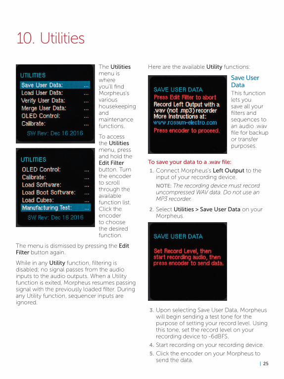
Here are the available Utility functions:
Save User DataThis function lets you save all your filters and sequences to an audio .wav file for backup or transfer purposes.
To save your data to a .wav file:
1. Connect Morpheus’s Left Output to the input of your recording device.
NOTE: The recording device must record uncompressed WAV data. Do not use an MP3 recorder.
2. Select Utilities > Save User Data on your Morpheus.
3. Upon selecting Save User Data, Morpheus will begin sending a test tone for the purpose of setting your record level. Using this tone, set the record level on your recording device to -6dBFS.
4. Start recording on your recording device.
5. Click the encoder on your Morpheus to send the data.
26 |
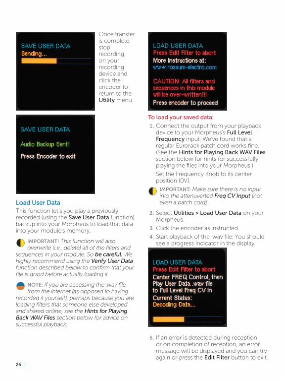
Once transfer is complete, stop recording on your recording device and click the encoder to return to the Utility menu.
Load User DataThis function let’s you play a previously recorded (using the Save User Data function) backup into your Morpheus to load that data into your module’s memory.
IMPORTANT! This function will also overwrite (i.e., delete) all of the filters and
sequences in your module. So be careful. We highly recommend using the Verify User Data function described below to confirm that your file is good before actually loading it.
NOTE: If you are accessing the .wav file from the internet (as opposed to having
recorded it yourself), perhaps because you are loading filters that someone else developed and shared online, see the Hints for Playing Back WAV Files section below for advice on successful playback.
To load your saved data:
1. Connect the output from your playback device to your Morpheus’s Full Level Frequency input. We’ve found that a regular Eurorack patch cord works fine. (See the Hints for Playing Back WAV Files section below for hints for successfully playing the files into your Morpheus.)
Set the Frequency Knob to its center position (0V).
IMPORTANT: Make sure there is no input into the attenuverted Freq CV Input (not even a patch cord).
2. Select Utilities > Load User Data on your Morpheus.
3. Click the encoder as instructed.
4. Start playback of the .wav file. You should see a progress indicator in the display.
5. If an error is detected during reception or on completion of reception, an error message will be displayed and you can try again or press the Edit Filter button to exit.

| 27
Once transfer is complete, click the encoder to return to the Utility menu.
Verify User DataThis function lets you play a previously recorded backup (using the Save User Data function) into your Morpheus to
ensure that it is intact and being played back at sufficient level.
This does not actually load the data into your Morpheus. Its purpose is to confirm that the backup file is valid, so that you can avoid loading an invalid file and deleting your existing data.
NOTE: If you are accessing the .wav file from the internet (as opposed to having
recorded it yourself), perhaps because you are loading filters that someone else developed and shared online, see the Hints for Playing Back WAV Files section below for advice on successful playback.
To verify your saved data:
1. Connect the output from your playback device to your Morpheus’s Full Level Frequency input. We’ve found that a regular Eurorack patch cord works fine. (See the Hints for Playing Back WAV Files section below for hints for successfully playing the files into your Morpheus.)
Set the Frequency Knob to its center position (0V).
IMPORTANT: Make sure there is no input into the attenuverted Freq CV Input (not even a patch cord)
2. Select Utilities > Verify User Data on your Morpheus.
3. Click the encoder as instructed.
4. Start playback of the .wav file. You should see a progress indicator in the display.
5. If an error is detected during reception or on completion of reception, an error message will be displayed and you can try again (try playing back at a hotter level) or press the Edit Filter button to exit.
6. If you don’t receive an error, you can proceed to load the data into your Morpheus using the Load User Data function described above.
Once the process is complete, click the encoder to return to the Utility menu.
Merge User DataThis function lets you read in a data file (filters and sequences) and copy any preset or sequence in that file

28 |
to your module, as long as its number is not already taken up with a saved filter or sequence already in your module.
So, if you have saved filters 303 and 306, and you load in a file that has filters 301–309, you’ll end up with the following:
301 and 302 from the merge file
303: your existing preset
304 and 305 from the merge file
006: your existing preset
007, 008, and 009 from the merge file
NOTE: 303 and 306 from the merge file will not be transferred.
Sequences work the same, with the exception that it would be possible to exceed the 20,000 step limit. In that case, any sequences that exceeded the limit would not be transferred.
To merge your saved data:
1. Connect the output from your playback device to your Morpheus’s Full Level Frequency input. We’ve found that a regular Eurorack patch cord works fine. (See the Hints for Playing Back WAV Files section below for hints for successfully playing the files into your Morpheus.)
Set the Frequency Knob to its center position (0V).
IMPORTANT: Make sure there is no input into the attenuverted Freq CV Input (not even a patch cord).
2. Select Utilities > Merge User Data on your Morpheus.
3. Click the encoder as instructed.
4. Start playback of the .wav file. You should see a progress indicator in the display.
5. If an error is detected during reception or on completion of reception, an error message will be displayed and you can try again (try playing back at a hotter level) or press the Edit Filter button to exit.
Once the process is complete, click the encoder to return to the Utility menu.
OLED ControlAs mentioned back in Chapter 6, OLED displays have long lifetimes under normal use, but if you leave your system
on 24/7 (or just want to ensure the longest possible life for our display), you can adjust the brightness of the display (which is also useful for optimizing it for the ambient lighting level of your work environment) and, optionally, you can set a time after which the display enters a screensaver mode. Both of these can help extend the life of your display.
NOTE: Once the screen saver has appeared, any button press or a turn of
the encoder will dismiss it and return to the regular display. Such encoder turns or button presses are not registered as control inputs.

| 29
ANOTHER NOTE: The screen saver will not appear when you are executing a Utilities
Menu function. However, it will appear if the Utilities Menu is displayed (but no function selected).
Here’s how it works:
1. Select Utilities > OLED Control on your Morpheus.
2. Turn the encoder to select a brightness level of 1-11. You’ll see the display change in brightness as you scroll through the values. The value number also changes color to indicate their effect on OLED life (Green=great, Yellow=okay, Red=beware if you leave your system on 24/7)
3. Click the encoder to move to the ScreenSaver setting.
4. Turn the encoder to select the time after which the screen saver will appear. Choices range from 2 minutes to 60 minutes and “Never.” If you consistently leave your system on long periods of time, “Never” is probably not a good choice.
NOTE: The screen saver is a small version of Morpheus’s frequency plot that moves
randomly around the display. Note that this plot is actually functional, responding in real-time to manual adjustments and CV inputs.
Calibrate
Your Morpheus is carefully calibrated at the factory. So, in normal circumstances, you shouldn’t have a need to recalibrate it.
However should abnormal circumstances present themselves, this function allows you to recalibrate your Morpheus.
Select Utilities > Calibrate on your Morpheus. The procedure is self-guiding. Simply follow the instructions on each screen.
When the encoder is pressed after the last step, the screen will briefly display “New Calibration Data Saved” then return to normal operation.
Load SoftwareThis function lets you load updated operating software into your Morpheus. The process is pretty much identical to
the Load User Data process described above.
1. Connect the output from your playback device to your Morpheus’s Full Level Frequency input.
2. Select Utilities > Load Software on your Morpheus.
3. Click the encoder as instructed.
4. Start playback of the .wav file. You should see a green percentage progress message in the display (see below). Again, see the Hints for Playing Back WAV Files section below if you’re having any problems.

30 |
5. If an error is detected during reception or on completion of reception, an error message will be displayed and you can try again or press the Global/Pause/Utilities button to exit.
Once transfer is complete, click the encoder to reboot your Morpheus and use your new software.
Load Boot SoftwareThis function loads an updated version of the special software that’s responsible for booting up your Morpheus.
The process is identical to the Load Software function above, except, of course, that you select Utilities > Load Boot
Software on your Morpheus and load an appropriate Boot Software file.
Load CubesThis function loads an updated version of Morpheus’s preconfigured filter cubes.
The process is also identical to the Load Software function above, except that this time, you select Utilities > Load Cubes on your Morpheus and load an appropriate Cubes file.
Manufacturing Test
This function provides a suite of tests to be used during manufacturing to ensure that everything on your Morpheus is working correctly. Unless something goes horribly wrong, there shouldn’t be a reason that you ever need to worry about it.
However, like Calibrate, it’s self-guiding, so if you’re just curious, you’re welcome to play with it, since it can’t do any harm.

| 31
Hints for Playing Back WAV FilesThe basic requirements for successful WAV file playback for software updates and data transfer is that the file should be played back at the highest possible level without distortion. As long as it doesn’t distort, the hotter the better.
We’ve had good luck playing WAV files directly from a computer (but see the warnings below) as well as smartphones and tablets.
In theory, any device that will play a WAV file without distorting the data should work.
However, here are some caveats:
> If you are steaming the file directly from the web, be sure that your data rate is sufficient to keep up. If necessary, wait until the file has been completely buffered before starting playback.
> If you are playing the file from a computer or phone, quit Facebook, your email client, and any other software that produces audio. Any other audio injected into the stream will cause the transfer to fail.
> If you’re using a smartphone, temporarily placing it in Airplane Mode will prevent any incoming call or message notifications from interfering with playback.
> We have found that Safari on the Mac plays the file in a way that often keeps it from being successfully recognized and decoded. If you are using Safari, we recommend downloading the WAV file to your computer and playing the file from the local copy using Quicktime Player.
> In fact, if you are having any problem streaming the file, downloading the file locally and playing it from there is a good alternative.
> If you do get an error message during a transfer (e.g., the level was too low, your computer generated extraneous audio, etc.), you can just correct the problem and try again. However, we’ve found that rather than just playing the file again from the beginning, it’s usually advisable to close the file, reopen it, and then start playback.

32 |
11. Factory Cubes
To come…

| 33

34 |
12. Specifications
FILTER CUBES289
FILTERS1000
FILTER SEQUENCES200
SEQUENCE STEPS 20,000 Dynamically Allocated
INPUTSAUDIO L/R2x 3.5mm mono socket100kΩ Input Impedance
FULL LEVEL FREQUENCY CV1x 3.5mm mono socket100kΩ Input Impedance
ATTENUVERTED FREQUENCY CV1x 3.5mm mono socket100kΩ Input Impedance
ATTENUVERTED MORPH CV1x 3.5mm mono socket100kΩ Input Impedance
ATTENUVERTED TRANSFORM CV1x 3.5mm mono socket100kΩ Input Impedance
PRESET SEQUENCER DEC1x 3.5mm mono socket100kΩ Input Impedance1.6V threshold
PRESET SEQUENCER INC1x 3.5mm mono socket100kΩ Input Impedance1.6V threshold
PRESET SEQUENCER RESET1x 3.5mm mono socket100kΩ Input Impedance1.6V threshold
OUTPUTSAUDIO L/R2x 3.5mm mono socket1kΩ Impedance
POWER REQUIREMENTS+/-12V (+/- 5%) via 16-pin, Doepfer-style connector
CURRENT DRAW135mA +12V, 25mA -12V (maximum)
DIMENSIONS18HP (W); Panel to power connector (with connector plugged in) 25mm (D)
SUPPLIED ACCESSORIES1x 16-pin, Doepfer-style cable4x M3 screws4x M2.5 screws4x Nylon washers1x Quickstart Guide

| 35
13. From Dave’s Lab: Circuit Protection
Eurorack suffers from the problem of power connector reversal. When 10 pin connectors are used, mis-insertion results in a swap of +12V and -12 V, and protection is easily accomplished using various techniques such as series diodes.
But more systems are providing the +5V supply and thus use the full 16 pin connector. When this is reversed, a diode-protected module is still safe, but the six connected ground pins in the module will short together the system’s +5V and +12V supplies, potentially damaging the power supply and any modules that use +5V.
To prevent this, Rossum Electro-Music modules deviate from the standard Eurorack power connector by leaving power connector pins 9 and 10 open, rather than connecting them to ground. When plugged in backwards, this leaves the system +12V supply disconnected. Since ground is still supplied by four pins as well the chassis and any patch cords connected to the module, the dropping of these two pins has no measurable effect on circuit performance, but it means that if a Rossum Electro module is accidentally plugged in backwards, no stress is placed on the +5V supply or modules that use it.

36 |
14. Acknowledgements
A number of wonderful people generously provided help, advice, encouragement, and inspiration during the development of Morpheus.
Many thanks from the Rossum Electro-Music team to:
Jim Aikin
Alex Anderson
James Bernard
Bob Bliss
Patrick Brede
Janis Chafin
Josh Cliffe
Richard Devine
Nancy Enge
Mihai Ionescu
Kurt Kurasaki
William Mathewson
David Phipps
Bill Putnum
Jeff Rona
Kirk Southwell
Tyler Thompson
Amon Tobin
Ben “DivKid” Wilson
And, it goes without saying (but, as we always do, we’ll say it anyway), our families for understanding all the late nights and weekends spent not having fun (or doing chores) with them.

| 37