morpheus build manual v0.95 -...
TRANSCRIPT

Morpheus V1.00a Build Manual Copyright 2009 William Henning
Building Morpheus v1.00a
Version 0.95
Copyright 2009 by William Henning
Updated documentation will always be available at http://Mikronauts.com
Morpheus v0.1 in mid-2008
http://Mikronauts.com 1 07/08/09

Morpheus V1.00a Build Manual Copyright 2009 William Henning
Table of ContentsIntroduction.........................................................................................................4
Top of board:..................................................................................................4Bottom of the Board:......................................................................................5X-Ray view of the top of the board, through the bottom:...............................6
Section One – Parts that go on the back of the board.......................................7CPU1..............................................................................................................8CPU2............................................................................................................11Keyboard......................................................................................................17Mouse...........................................................................................................17EEPROM......................................................................................................18RTC..............................................................................................................19Flash 1..........................................................................................................20Flash 2..........................................................................................................2074HC139 Decoder........................................................................................2174HC574 Latch UH......................................................................................2174HC574 Latch UL.......................................................................................22SRAM...........................................................................................................227805 Voltage Regulator................................................................................23
Section Two – Parts that go on the top of the board........................................24CPU1............................................................................................................24CPU2............................................................................................................25EEPROM......................................................................................................25RTC..............................................................................................................26FLASH1........................................................................................................26FLASH2........................................................................................................2674HC139 Decoder........................................................................................2774HC574 Latch UH......................................................................................2774HC574 Latch UL.......................................................................................28SRAM...........................................................................................................283.3VCAP CAPACITORS..............................................................................30
Section 3 – Installing the connectors................................................................31Audio Connector...........................................................................................31Mouse Connector.........................................................................................32Keyboard Connector....................................................................................32VGA Connector............................................................................................33EXP1 & EXP2...............................................................................................34MORPHBUS & Power Switch......................................................................34H-COMM1 & H-COMM2...............................................................................35Product Shots...............................................................................................35
Section 4 – The Smoke Test............................................................................37Test #1: Power to Ground Shorts.................................................................37Test #2: Voltage Regulation.........................................................................37
http://Mikronauts.com 2 07/08/09

Morpheus V1.00a Build Manual Copyright 2009 William Henning
Test #3: Power at Integrated Circuits...........................................................38Test #4: Morpheus Sub Systems.................................................................39EEPROM Test..............................................................................................39Flash1 Test:..................................................................................................40Flash2 Test:..................................................................................................40XMM test:.....................................................................................................40
Appendix A: Data Sheets.................................................................................41Appendix B: Required Tools.............................................................................41
http://Mikronauts.com 3 07/08/09

Morpheus V1.00a Build Manual Copyright 2009 William Henning
IntroductionAs you look at your Morpheus, you will see the white silk screening showing you where the parts go. Most of the parts locations are indicated on the top of the board, however in my experience, you will have a much easier build if most of the passive components are actually placed on the bottom of the board.
To make your life easier, I am including some views of the board without the clutter of the traces and pads – this way you will find the part locations even easier.
Top of board:
http://Mikronauts.com 4 07/08/09

Morpheus V1.00a Build Manual Copyright 2009 William Henning
Bottom of the Board:
I left the part name layer turned on so you can see which resistors are where on the bottom of the board.
http://Mikronauts.com 5 07/08/09

Morpheus V1.00a Build Manual Copyright 2009 William Henning
X-Ray view of the top of the board, through the bottom:
This view will be VERY useful to you when mounting the passive components on the back of the board.
http://Mikronauts.com 6 07/08/09

Morpheus V1.00a Build Manual Copyright 2009 William Henning
Section One – Parts that go on the back of the board
Here is what the top of a Revision 1.00a Morpheus board looks like:
And here is what the bottom of the board looks like:
http://Mikronauts.com 7 07/08/09

Morpheus V1.00a Build Manual Copyright 2009 William Henning
CPU1
install a 5MHz crystal at Xtal install .1uF bypass capacitor C5 install 10uF electrolytic capacitor C14 with the negative lead of C14 being next to C5
Note that the leads on the electrolytic capacitor had not been trimmed yet.
install 10K resistors R18, R19 install 10nF audio capacitors C3, C4 install 1uF ceramic capacitors C1, C2
http://Mikronauts.com 8 07/08/09

Morpheus V1.00a Build Manual Copyright 2009 William Henning
CPU1 – Continued
install 2K2 resistors R20-R27 (you can substitute 2K resistors) Bending the leads out like this keeps the resistors from falling off the board when you turn
the board around – and keeps them nice and low on the PC board.
CPU1 – Completed
If you followed the instructions above, your board should now look like this:
Now that wasn't so bad, was it?
http://Mikronauts.com 9 07/08/09

Morpheus V1.00a Build Manual Copyright 2009 William Henning
Here is the bottom view:
http://Mikronauts.com 10 07/08/09

Morpheus V1.00a Build Manual Copyright 2009 William Henning
CPU2
Install a 5MHz crystal at XTAL1
(OPTIONAL) install 10K pullup resistor R11 (pulls up RESET)
http://Mikronauts.com 11 07/08/09

Morpheus V1.00a Build Manual Copyright 2009 William Henning
CPU2 – Continued
Install R28-R29 10K pull up resistors on TOP of the board BEFORE the net step
(OPTIONAL) install 8 pin DIP socket EEPR2 (for optional EEPROM)
I suggest installing R28, R29 and the DIP socket even if you are not planningto use the EEPROM for CPU2 as it is FAR easier at this stage than re-workingthe board later.
http://Mikronauts.com 12 07/08/09

Morpheus V1.00a Build Manual Copyright 2009 William Henning
CPU2 – Continued
install .1uF bypass capacitor C6 install 10uF electrolytic capacitor C15
The 256 color VGA circuit requires the following ten resistors:
install 270R resistors R9, R10 right next to the crystal for CPU2
http://Mikronauts.com 13 07/08/09

Morpheus V1.00a Build Manual Copyright 2009 William Henning
CPU2 – Continued
Here they are on the bottom of the photo (and board):
install 470R resistors R2, R5, R8
http://Mikronauts.com 14 07/08/09

Morpheus V1.00a Build Manual Copyright 2009 William Henning
CPU2 – Continued
install 1K resistors R1, R4, R7
Let's see what the bottom of the board looks like now:
We are almost done building the 256 color VGA DAC's!
http://Mikronauts.com 15 07/08/09

Morpheus V1.00a Build Manual Copyright 2009 William Henning
CPU2 - Continued
install 2K resistors R3, R6
BE VERY CAREFUL TO INSTALL THE RIGHT RESISTORS IN THE RIGHTPLACES, OTHERWISE THE COLORS WILL BE WRONG!
Note: it is possible to populate the board for “regular” 64 color VGAhowever the resulting layout will look a bit messy
http://Mikronauts.com 16 07/08/09
Morpheus V1.00a Build Manual Copyright 2009 William Henning
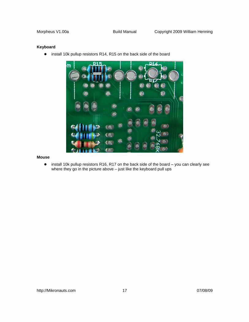
Keyboard
install 10k pullup resistors R14, R15 on the back side of the board
Mouse
install 10k pullup resistors R16, R17 on the back side of the board – you can clearly see where they go in the picture above – just like the keyboard pull ups
http://Mikronauts.com 17 07/08/09

Morpheus V1.00a Build Manual Copyright 2009 William Henning
EEPROM
install 10k pullup resistors R12, R13 on the back of the board install 100nF bypass capacitor C10 on the back of the board
C10 will go to the right of the two pull up resistors you just installed – do you see the two empty holes between them and the VGA resistors just above here?
http://Mikronauts.com 18 07/08/09
Morpheus V1.00a Build Manual Copyright 2009 William Henning
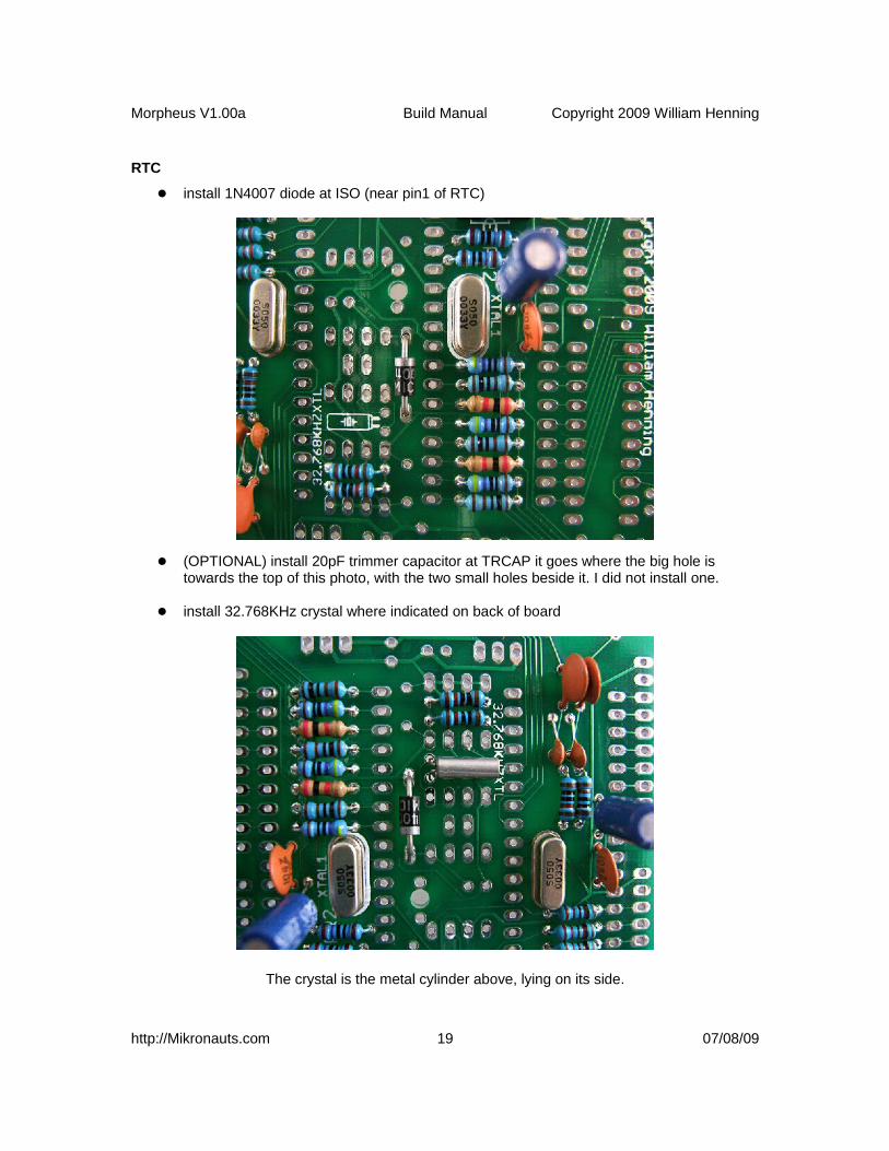
RTC
install 1N4007 diode at ISO (near pin1 of RTC)
(OPTIONAL) install 20pF trimmer capacitor at TRCAP it goes where the big hole is towards the top of this photo, with the two small holes beside it. I did not install one.
install 32.768KHz crystal where indicated on back of board
The crystal is the metal cylinder above, lying on its side.
http://Mikronauts.com 19 07/08/09

Morpheus V1.00a Build Manual Copyright 2009 William Henning
Flash 1
Install 100 nF decoupling capacitor C11
Flash 2
install 100nF decoupling capacitor C12 – it goes right below C11 as shown in the photo above – next to the eight pin dip socket
http://Mikronauts.com 20 07/08/09

Morpheus V1.00a Build Manual Copyright 2009 William Henning
74HC139 Decoder
Install 100 nF decoupling capacitor C13 right below the VGA connector
install 10k pullup resistors R10-10K and R11-10K on the top back side of the board – you can see them right below the capacitor roughly in the middle of the photo
74HC574 Latch UH
install 100nF decoupling capacitor C9
http://Mikronauts.com 21 07/08/09

Morpheus V1.00a Build Manual Copyright 2009 William Henning
You can see it right beside C13 in the upper left of this photo
74HC574 Latch UL
install 100nF decoupling capacitor C8, you can see it in the middle of the photo
SRAM
install 100nF decoupling capacitor C7
You can see C7 roughly in the middle, near the holes for the SRAM socket.
http://Mikronauts.com 22 07/08/09
Morpheus V1.00a Build Manual Copyright 2009 William Henning
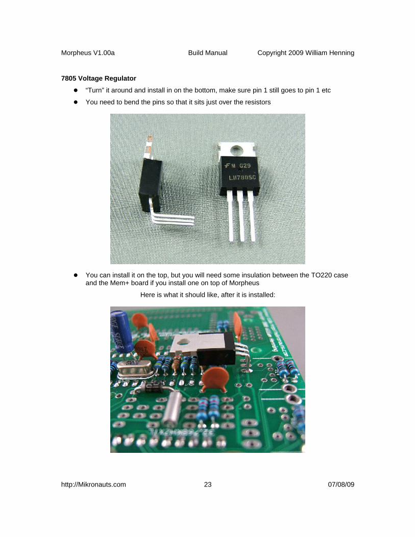
7805 Voltage Regulator
“Turn” it around and install in on the bottom, make sure pin 1 still goes to pin 1 etc
You need to bend the pins so that it sits just over the resistors
You can install it on the top, but you will need some insulation between the TO220 case and the Mem+ board if you install one on top of Morpheus
Here is what it should like, after it is installed:
http://Mikronauts.com 23 07/08/09

Morpheus V1.00a Build Manual Copyright 2009 William Henning
Section Two – Parts that go on the top of the board
CPU1
Install 40 pin DIP socket, pin 1 is towards the audio connector
Some sockets won't sit flush on the board due to the solder bumps sitting on a too-wide rim. If this bothers you, you can use socket strips, thinner sockets, or use a dremel to cut away some of the plastic. As long as the pins come out on the other side of the board for both sides of the socket it should be ok.
http://Mikronauts.com 24 07/08/09

Morpheus V1.00a Build Manual Copyright 2009 William Henning
CPU2
Install 40 pin DIP socket, pin 1 is towards H-COMM2
EEPROM
install 8 pin dip socket on top of board, pin1 towards SRAM
Sorry for the poor focus on the socket – the camera would not lock on it.
http://Mikronauts.com 25 07/08/09
Morpheus V1.00a Build Manual Copyright 2009 William Henning
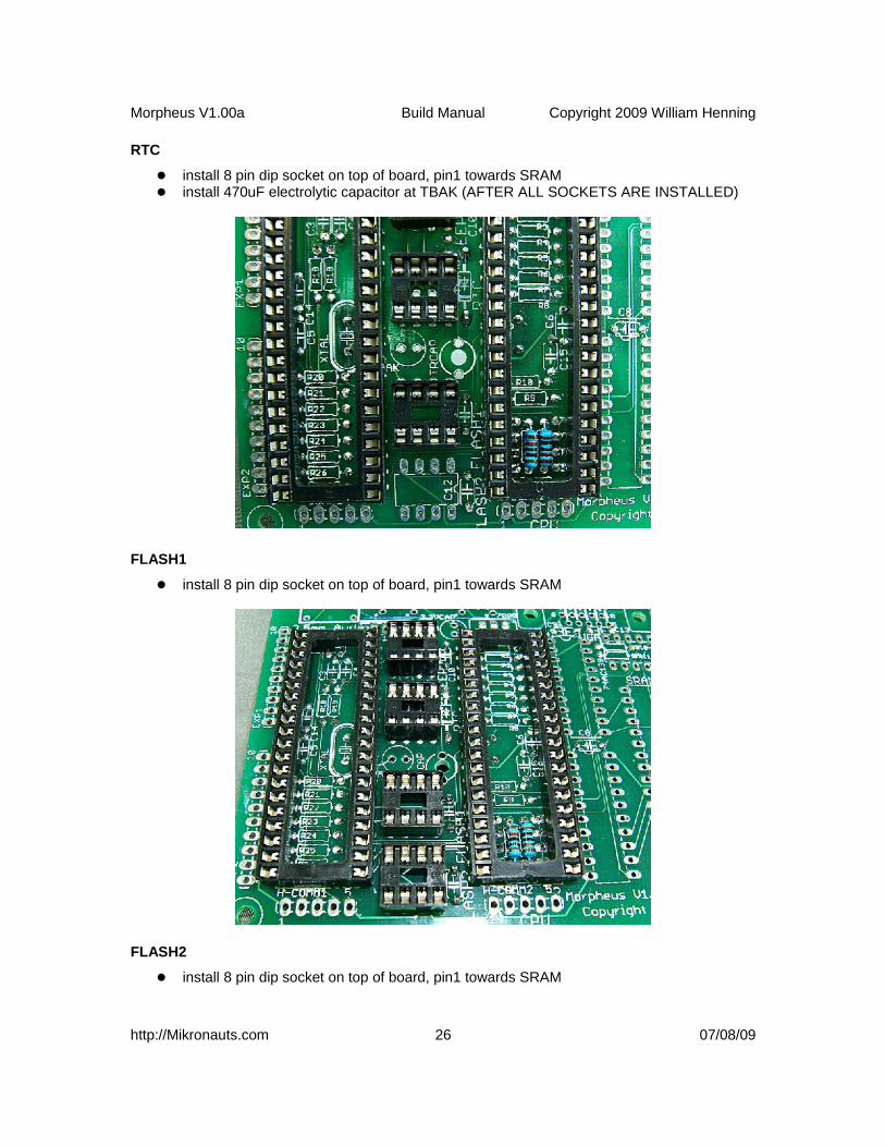
RTC
install 8 pin dip socket on top of board, pin1 towards SRAM install 470uF electrolytic capacitor at TBAK (AFTER ALL SOCKETS ARE INSTALLED)
FLASH1
install 8 pin dip socket on top of board, pin1 towards SRAM
FLASH2
install 8 pin dip socket on top of board, pin1 towards SRAM
http://Mikronauts.com 26 07/08/09

Morpheus V1.00a Build Manual Copyright 2009 William Henning
74HC139 Decoder
Install 16 pin DIP socket at 74HC139, pin 1 is towards the far end of the board
install 100nF decoupling capacitor C13 ON THE BOTTOM OF THE BOARD
74HC574 Latch UH
Install 20 pin DIP socket at UH, pin 1 is towards the VGA connector
http://Mikronauts.com 27 07/08/09

Morpheus V1.00a Build Manual Copyright 2009 William Henning
74HC574 Latch UL
Install 20 pin DIP socket at UL, pin 1 is towards the VGA connector
SRAM
Install 32 pin DIP socket, pin1 is towards the VGA connector
http://Mikronauts.com 28 07/08/09

Morpheus V1.00a Build Manual Copyright 2009 William Henning
LM1117-3.3 or AS2810-3.3 Voltage Regulator
I install a TO-263-3 version of the AS2810-3.3 on top of the board
TO-220 case regulators should go on the bottom, make sure pin 1 is at pin 1
I have a lot of AS2810AT 3.3V regulators in stock in a TO-263-3 case – the leads need to be bent before they can be used in place of the LM1117-3.3 the BOM lists. I listed the LM1117-3.3 as DigiKey does not stock the AT2810AT-3.3.
To modify a TO-263-3 case voltage regulator, all you have to do is straighten the pins. You can see the original bent pins, the intermediate stage and the end result of straightening above.
http://Mikronauts.com 29 07/08/09

Morpheus V1.00a Build Manual Copyright 2009 William Henning
470uF RTC Capacitor
Since all the sockets are in, it is time to install the big capacitor for backing up the RTC! If you don't have a 470uF capacitor, pretty much anything 330uF or higher should work.
3.3VCAP CAPACITORS
actually one is for the 5V regulator – I install both on top
I am cheating a bit here, as this photo is also for showing the installed audio connector, referred to on the next page.
http://Mikronauts.com 30 07/08/09

Morpheus V1.00a Build Manual Copyright 2009 William Henning
Section 3 – Installing the connectors
(They go on TOP of the board)
Audio Connector
the holes may be too small for the leads depending on the specific connector – either drill a hole next to the existing three holes (I would recommend .1” to the left), run some wires to a different style of audio jack, or run wires to two RCA line level audio jacks like I do.
Below, I show how I used a dremel to shave the pins until they would fit – thanks TrapperBob!
http://Mikronauts.com 31 07/08/09

Morpheus V1.00a Build Manual Copyright 2009 William Henning
Mouse Connector
Make sure there is room between the pullup resistors for the tab to push thru
Press to fit
Keyboard Connector
Make sure there is room between the pullup resistors for the tab to push thru
Press to fit
http://Mikronauts.com 32 07/08/09

Morpheus V1.00a Build Manual Copyright 2009 William Henning
VGA Connector
Be careful of bypass capacitors C9 and C13 – if you mounted them on top you will have trouble fitting the VGA connector
Press to fit
Power Connector
For this revision of the board, use a two screw terminal with 0.2” (5.08mm) spacing
the power jack holes are too small, and + and – are reversed
I fixed the power reversal problem for this revision TWICE, that's why its back
http://Mikronauts.com 33 07/08/09

Morpheus V1.00a Build Manual Copyright 2009 William Henning
EXP1 & EXP2
install on the top of the board, solder the tails on the bottom
(OPTIONAL) EXP2 if you want to monitor the FLASH1 & FLASH2 SPI signals
MORPHBUS & Power Switch
install on the top of the board, solder the tails on the bottom
I use a SPDT 0.1” spacing terminal mini-switch
http://Mikronauts.com 34 07/08/09

Morpheus V1.00a Build Manual Copyright 2009 William Henning
H-COMM1 & H-COMM2
install on the top of the board, solder the tails on the bottom
Product Shots
http://Mikronauts.com 35 07/08/09

Morpheus V1.00a Build Manual Copyright 2009 William Henning
More Product Shots
And finally, here is a nice perspective view:
http://Mikronauts.com 36 07/08/09

Morpheus V1.00a Build Manual Copyright 2009 William Henning
Section 4 – The Smoke TestIf you have gotten this far, and are reasonably skilled at soldering, you probably have a working board – but just in case something went wrong, it would be nice to make sure that you don't fry the expensive chips!
PLEASE TRY THESE TESTS!
(and feel free to do more testing – I welcome suggestions for additional tests)
Test #1: Power to Ground Shorts
Read the resistance between 3.3V and GND somewhere handy on the board – I'd suggest pin 1 and pin 2 of EXP1 or EXP2 as being easy to get to.
If you read less than 300 ohms, you have a short somewhere. Look over everywhere you soldered, use a bright light and a magnifying glass.
Once you found the short, use solder wick to clear it.
Repeat this test until there are no more shorts.
Test #2: Voltage Regulation
Apply power to the board and turn it on.
If either of the voltage regulators gets VERY hot, turn the power off, and go back to Test#1, checking for shorts. Make sure the power is hooked up right, that is + and – are not reversed.
If everything looks OK, check the +5 supply – a handy place to check is on the MORPHBUS connector. Otherwise make sure the voltage regulator is mounted correctly, and that there are no shorts.
Check the +3.3 supply rail – again, pins 1&2 of the EXP1 or EXP2 connectors are handy for this.
If you don't get a voltage between 3.25 and 3.35, check for shorts, and check to see that the regulator is mounted correctly.
http://Mikronauts.com 37 07/08/09

Morpheus V1.00a Build Manual Copyright 2009 William Henning
Test #3: Power at Integrated Circuits
Check the power and ground pins on the sockets for all the chips.
I STRONGLY suggest you print the pin out page from all the data sheets to help you test the board.
CPU1CPU2EEPROMEEPR2RTCFLASH1FLASH274HC13974HC574 UH74HC574 ULSRAMMORPHBUSEXP1EXP2H-COMM1H-COMM2MOUSEKEYBOARDVGA
(next version of this document will give the pin numbers, for now refer to data sheets)
http://Mikronauts.com 38 07/08/09
Morpheus V1.00a Build Manual Copyright 2009 William Henning
*** WARNING ***REMEMBER TO OBSERVE STATIC ELECTRICITY PRECAUTIONS WHEN HANDLING THE CHIPS AND A BOARD WITH CHIPS! YOU SHOULD USE A GROUNDING STRAP WHEN HANDLING STATIC SENSITIVE DEVICES!
Test #4: Morpheus Sub Systems
In order to check the keyboard and mouse, you need some LED's and some 270R resistors. Mount them on a solder less breadboard, with the LED's anode connected to one of pins 2-10 in EXP1, the cathode going through the resistor to ground (pin 2 on the connector). Don't forget the resistors, otherwise you may damage the I/O pins on your propeller!
At this point, install a Propeller into the CPU1 socket. You should NOT install any other chips yet.
For the following tests, pyour PropPlug into H-COMM1
Audio Test:
connect the the audio output to an amplifier download and run Chip's singing monks demo run it
Keyboard Test:
Plug a PS/2 keyboard into the Keyboard socket. Download and run “kbtest.spin” Press different keys, and you should see the ASCII code on the eight LED's
Mouse Test: (using a keyboard)
Plug a PS/2 keyboard into the Keyboard socket. Download and run “mousetest.spin” Press different keys, and you should see the ASCII code on the eight LED's
At a later date I will write a “real” mouse test, however the keyboard suffices for testing the mouse socket and wiring.
EEPROM Test
Install a 24LC256 into the EEPROM socket above the RTC Download and program the “kbtest.spin” into the EEPROM Power down, then power up Morpheus see if it runs the test from the EEPROM
http://Mikronauts.com 39 07/08/09

Morpheus V1.00a Build Manual Copyright 2009 William Henning
RTC test:
Install the PCF8563 into the RTC socket Download and run “RTCTest.spin” Run PST press enter, that will display the current time/date enter the current date/time as YY/MM/DD HH:MM:SS – ie 09/07/08 13:54:33<enter> that will set the time power Morpheus off power it on run “RTCTest.spin” again it should show the correct time date
Flash1 Test:
Install the W25X080 into FLASH1 Download and run “Flash1Test.spin” Run PST, and press enter PST will tell you the ID and size of the Flash chip PST will: program, read, erase a sector and give you pass/fail for each stage
Flash2 Test:
Install the W25X080 into FLASH2 Download and run “Flash2Test.spin” Run PST, and press enter PST will tell you the ID and size of the Flash chip PST will: program, read, erase a sector and give you pass/fail for each stage
If both flash tests pass, leave the Flash chip in Flash2, and install the 23K256 into Flash1
For the following two tests, plug your PropPlug into H-COMM2
VGA 256 color test:
Install the second Propeller into the CPU2 socket Plug your PropPlug into H-COMM2 Plug a VGA monitor into the VGA connector Download and run the “VGA256test.spin” file You should see it cycle through some test patterns if the shades of red, green, or blue are out of order, check that you soldered the correct
resistor values into the D/A converter under CPU#2
XMM test:
Install the 74HC139 decoder chip into its socket Install the 74HC574 chips into their sockets Install the BS62LV4006 chip into the SRAM socket Plug your PropPlug into H-COMM2 Plug a VGA monitor into the VGA connector Download and run the “XGA256test.spin” file If you see it draw a red/green/blue pattern you are done!
http://Mikronauts.com 40 07/08/09

Morpheus V1.00a Build Manual Copyright 2009 William Henning
That's it! If all the tests pass, you have successfully built your first Morpheus!
NOTE: I will be uploading the test programs to my site as they are ready for your use.
Appendix A: Data SheetsPropeller: http://www.parallax.com/Portals/0/Downloads/docs/prod/prop/WebPM-v1.1.pdf
Propeller: http://www.parallax.com/Portals/0/Downloads/docs/prod/prop/PropellerDatasheet-v1.2.pdf
SRAM: http://www.bsi.com.tw/product/BS62LV4006.pdf
RTC: http://www.standardics.nxp.com/products/pcf/datasheet/pcf8563.pdf
EEPROM: http://ww1.microchip.com/downloads/en/DeviceDoc/21203P.pdf
SPI RAM: http://ww1.microchip.com/downloads/en/DeviceDoc/22100D.pdf
FLASH: http://www.winbond.com.tw/NR/rdonlyres/0971C40C-F202-49CA-90AF-0F0268ECF0E5/0/W25X10L_W25X20L_W25X40L_W25X80L.pdf
74HC139: http://www.nxp.com/acrobat_download/datasheets/74LV139_4.pdf
74HC574: http://www.nxp.com/acrobat_download/datasheets/74LV574_4.pdf
Appendix B: Required Tools
Multimeter capable of measuring at least DC Volts and Resistance Needle nose pliers Diagonal pliers desoldering pump soldering iron (ideally temperature controlled) solder
http://Mikronauts.com 41 07/08/09