modeling of an innovative frontal car structure: …
TRANSCRIPT
MODELING OF AN INNOVATIVE FRONTAL CAR STRUCTURE: SIMILAR DECELERATION CURVES AT FULL OVERLAP, 40 PER CENT OFFSET AND 30 DEGREES COLLISIONS
W.J. Witteman R.F.C. Kriens Eindhoven University of Technology Laboratory for Automotive Engineering Eindhoven, The Netherlands Paper Number 98-S l-0-04
ABSTRACT
The improved frontal crashworthiness of cars necessitates totally new design concepts, which take into account that the majority of collisions occur with partial frontal overlap and under off-axis load directions. Realistic crash tests with partial overlap have shown that conventional longitudinal structures are not capable of absorbing all the energy in the car front without deforming the passenger compartment. The reason for this is that the structure of the longitudinal members is specifically designed for meeting the more relaxed requirements of the compulsory full overlap test, in which both longitudinals are loaded axially.
Increased protection for the entire collision spectrum can be obtained by a frontal structure consisting of two special longitudinal members, which combine a higher bending resistance without increasing the axial stiffness. In addition the longitudinal members are supported by a cable connection system for symmetric force distribution. If only one of the longitudinal members is loaded during a partial overlap crash, the cable connection system will force the other longitudinal member to crumple as well. This results in normal programmed energy absorption. With this revolutionary concept a complete frontal car structure is designed with almost the same stiffness for all overlap percentages and impact angles, resulting in one crash pulse which can be optimized for minimal injury of the occupants.
The influence of various crash situations on the amount of energy absorbed by this total vehicle model and specified for important structural parts will be demonstrated by means of numerical simulations. Also important construction details, necessary for a well functioning of the designed cable supported frontal car structure, will be mentioned.
INTRODUCTION
For improved frontal car safety it is necessary to design a structure that absorbs enough energy in each realistic crash situation. To protect the occupants, the
passenger compartment should not be deformed and intrusion must be avoided too. To prevent excessive deceleration levels, the available crush distance in front of the passenger compartment must be used completely for a predetermined crash velocity. This implies that in a given vehicle concept the structure must have a specific stiffness. Normally, the two main longitudinal members will absorb most of the crash energy with a progressive folding deformation of a steel column. The main problem is that in real car collisions these two longitudinals often are not loaded axially in a synchronous fashion. The majority of collisions occur with partial frontal overlap, in which only one longitudinal is loaded, or with an off-axis load direction. This implies that most longitudinals fail under a premature bending collapse rather than a much more energy absorbing progressive folding pattern. This gives rise to two design conflicts. The first conflict is that the same amount of energy must be absorbed with either one or with two longitudinals. The second conflict is that the same amount of energy must be absorbed in the case of an off-axis impact angle as in the case of a normal incidence impact. These problems can not be solved by just increasing the stiffness of the longitudinals in such a way that each longitudinal is capable of absorbing all of the energy. To absorb enough energy, a stiff longitudinal is needed for the offset crash in which normally only one longitudinal is loaded. The same longitudinal must be more supple in case of a full overlap crash, since both longitudinals must not exceed the desired deceleration level (Witteman 1993). In addition, a stiff longitudinal is needed to absorb enough energy in an off-axis load direction (e.g. a crash test with a 30 degrees barrier) resulting in a higher bending resistance to help transform off-axis loads into axial loads and to prevent a bending collapse. The same but more supple longitudinal is needed in the case of a normal axial load to avoid overly high deceleration forces.
To solve this design problem with its contradictory requirements, a new approach is needed in which the design for the frontal car structure is decomposed into separate parts each fulfilling its own function. The combination of these parts yields a complete vehicle
194

structure which meets the requirement that in each crash situation (off-axis, offset and full overlap) nearly the same energy is absorbed and a similar deceleration level is obtained.
The next section presents a design solution based on this approach. It consists of a longitudinal with conventional axial stiffness but offering a much higher bending resistance. Furthermore, in the following section a new cable-supported system is supplemented to the designed longitudinals to provide a solution for the offset problem mentioned.
A NEW DESIGNED LONGITUDINAL MEMBER
The new concept is based on the design philosophy that an optimal longitudinal member must be functionally decomposed into two separate systems: the first, called the crushing part, guarantees the desired stable and efficient energy absorption. The other, called the supporting part, guarantees the desired stiffness in the transverse direction, see Figure 1. This latter part is necessary to allow enough energy absorption during an off-axis collision and to give enough support with a sliding wall to protect the crushing part against a bending collapse.
A square profile is chosen for the crushing part with a width of 70 mm outside and a thickness of 2 mm (Witteman 1995). The width dimensions of the crushing part are limited, as it has to fit within the available interior dimensions of the supporting part, depending on the available space between the engine and wheel envelope. The dimensions are based on a popular compact class car. The total length is 980 mm. The supporting part consists of four very stiff square profiles that lit into each other and may slide each over the other, like a telescope. Flanges prevent the telescope from falling apart. The overlap of the four supporting parts is maximized to 80 mm, this yields a high bending resistance and the supporting parts slide well into each other. Two supporting squared rings are necessary to prevent a bending collapse of the crushing part in the larger rear parts of the telescope. The same length of 980 mm can be shortened to 320 mm. To achieve a maximum deformation length, while taking into account the two supporting rings, the length of the supporting profiles must be from bumper to fire wall side successively: 280 mm, 300 mm, 320 mm and 320 mm. In this case, the available deformation length is 660 mm, 67.3 per cent of the original length. This must be enough for a compact class car. The maximal theoretical effective deformation is about 72.5 per cent of the length not deformed (Wierzbicki). Note that due to the presence of the rigid engine, in most collision situations the residual length of the longitudinal could not be less than the engine length. See Figure 2 for more details. The space between the corners of the crushing part and the inside of the supporting part is only 0.5 mm. At both ends of the longitudinal member, the two functional components are joined with a rigid plate.
Figure 1. Interior view of the longitudinal member.
195

560 l
780 4 *
Figure 2. Drawing of the longitudinal member.
The unusual angular orientation of the crushing part along the longitudinal axis of 45” with respect to the orientation of the enveloping support part has several advantages. At its corners the crushing part is supported by the enveloping square. No material deforms to the outside at the corners, which implies that at this position contact with the supporting part does not disturb the folding process. The narrow position of the crushing part in the enveloping supporting part gives a continuous sliding force as a support against bending. Note that during the deformation process the first part of the supporting structure with the smallest inner dimensions slides together with the folding front to the rear. After full deformation all the folds are packaged in the first supporting part. Figure 3 shows the lobes of the crushing part inside the supporting part after deformation.
Figure 3. Crushing part inside the boundaries of the supporting part after deformation.
The space needed for undisturbed folding is always guaranteed. The width growth of this preferred asymmetric fold (Witteman 1994) is nearly half of the not deformed width. This extra needed space is available due to the rotated orientation within the enveloping square.
The result is a longitudinal member with a conventional stiffness for stable energy absorption during a full overlap crash. It also has an extremely high bending resistance to absorb also energy during an offset or off-axis
collision, because a transverse load component can be transferred to an axial load.
Nevertheless, it is better to reach the same amount of energy absorption in the case of an offset crash as in a full overlap crash. Although this can be reached by further increasing the wall thickness of the supporting part, it is impossible to maintain an acceptable mass for the entire structure. Energy absorption by bending is very inefficient. A considerable amount of energy absorption is only possible with heavy structures. The only way to reach the same energy absorption and deformation length for an offset crash compared to a full overlap crash is to force the unloaded longitudinal to crumple as well, by means of a stable axial folding process. This is not possible with a very rigid transverse structure in the front. Bending moments will be introduced that are always too high. Also, the engine between the longitudinals reduces the possible shortening after a rigid transverse beam in front of the engine hits the engine.
An interesting solution is the addition of two cables and two bars to the designed longitudinals. This new design idea will be introduced in the next section (see Figure 4). This cable connection will force the unloaded longitudinal of an offset crash to perform axial shortening with a tensile force to the rear.
THE CABLE CONNECTION SYSTEM FOR A SYMMETRIC FORCE DISTRIBUTION
In Figure 4 a schematic sketch of a cable-supported frontal car structure is given. The system consists of two bars, two cables and four cable guides. The stiff bars are placed within the longitudinal members. At the front of the vehicle, they are connected with the cross member. The bars are longer than the longitudinals and extend beyond the vehicle’s firewall. A cable is connected to the end of
196

each bar. This cable is guided to the front end of the other longitudinal via two cable guides, where it is connected to the cross member. The working principle is rather simple: if one longitudinal is loaded and starts deforming, the bar moves backwards and pulls the cable, which leads the crushing force via the cable guides directly to the other, unloaded, longitudinal. The transmission of force is without loss of energy. Note that if both longitudinals are loaded (full overlap crash), the cable construction has no influence on the crash behavior.
Before the crash After fhe crash
/ Crossmember
Figure 4. Principle sketch of a cable-supported longitudinal structure.
This cable concept could be built into all cars with conventional frontal structures. However, the novel design concept described offers two important advantages, which make it very suitable for combination with the cable construction. The bars need to have sufficient space to move back-wards. Because intrusion of the passenger compartment is not desirable, the bars must move under the vehicle. This means that the longitudinal members need to be positioned under a slight angle (higher on the bumper side, lower on the firewall side), due to the prescribed compulsory height at which the forces must be led into the structure. The first advantage is that the novel design concept is well suited to be positioned under an angle. Its high bending resistance guarantees that the structure will not collapse in a premature bending collapse, unlike most conventional longitudinal members. Second, the new design concept guarantees stable folding of the crushing part under all circumstances. Most conventional longitudinals have all kinds of connections with other parts under the bonnet, which can easily disturb the folding process. A stable folding process is necessary, because the bar is placed within the crushing longitudinal and should always be free to move back-wards. (Unstable folding would prevent the bar from sliding within the narrow space of the crushing profile. This would cause the cable system to stop working correctly). To avoid any
transverse forces on the sliding bar, the cable is guided through the center of the bar. This is possible if the two bars are formed like a U-profile and the cable guides fit into these U-bars. See Figures 5 and 6 for more details.
Figure 5. Top view of the cable-supported longitudinal structure.
Figure 6. Cross-section of the cable around the cable guide disk inside the bar.
197

Figure 7. 3D open view of the cable-supported longitudinal structure.
A steel 8-string wire-rope cable with a diameter of 20 mm has a fracture force of 279 kN. That means that a force up to 167 kN does not deform the cable plastically, Simulations (Slaats 1996) showed that in a real offset crash the peak load is below this value.
The free space inside the stable asymmetric deformed square crushing part is decreased to about half the original width. This was confirmed by simulations and experiments in our laboratory and done by others (Beermann 1982). This 50 per cent decrease means that the inner dimension of the square crushing part after forming folds will be nearly 33 mm. To prevent each disturbance of the regular folding process, and to guarantee enough sliding space, an outside width of 32 mm of the square sliding bar is chosen.
The cable guide disk has a minimized height of 20 mm, the same as the cable diameter. This is important because the bar must not be weakened more than necessary.
The buckling load of the bar was calculated to be 239 kN. This is also more than the expected peak load during a crash. For the buckling load, the free length of the bar is the same as the longitudinal length. Behind the firewall extra leading support for the sliding bar is necessary to ensure that movement only occurs in the axial crush direction. During the crash, the free buckling length decreases by additional support from the formed folds.
In Figure 7, the assembly of the new design concept with the cable connection system can be seen. In addition, extra cable guide rings preventing the cable from slipping off the disk and a pin mounted to the firewall at the
crossing point of the cables are showed. Note that the center lines of the cable, bar and longitudinal fall together yielding axial forces only. The position of this cable- supported structure built inside a car is under a slight angle, therefore the two bars can move freely to the rear under the car floor during a crash,
BUILDING THE LONGITUDINAL STRUCTURE IN A NUMERIC FRONTAL CAR MODEL
Since a simulation has shown that the principle of the cable support works without disturbing the regular folding process of the longitudinals (Witteman 1996), a complete frontal car model is useful for evaluating more realistic crash situations. Just in case of an offset or an oblique crash situation, it is important that the model can move realistically. In a realistic test procedure, a vehicle moves freely with a velocity against a rigid stationary obstacle. Due to asymmetric forces during offset or oblique collisions, the back of the vehicle could turn a little, which implies an extra bending moment on the longitudinals. In addition, the mass inertia of the structure has an influence on the crash behavior. Especially the bars inside the longitudinals are stopped abruptly.
The longitudinals are responsible for the largest part of the energy absorption, for the necessary repeating folding process it is important that there is a good load introduction in axial direction. In case of a 30 degrees collision against a rigid barrier, the stiff corner of the first supporting part in front of the longitudinal will generate a bending moment, which can cause a bending collapse. To
198

avoid this rotation, the front of the first profile is changed into a flattened top of 60 degrees. This top can also provide the connection between the support profiles and the bumper. The top deforms in such a way that the moment applied on the first profile will be reduced. The bar inside the crushing part, which has a rigid connection with the stiff supporting part, has in case of a deformable top a less abrupt deceleration during the impact. This is important to prevent a buckling caused by its own inertia.
The frontal model should contain the most important structural parts that influence the way of energy absorption, The aim is to avoid deformation of the passenger compartment; all the crash energy must be absorbed by the total front structure. This implies that the frontal model boundary starts at the deformable firewall, which is connected to a not deformable cage. Rigid nodes on the wall borders, which also contain a part of the mass distribution of the not modeled vehicle side, can simulate this cage. In front of the cage the following deformable and rigid components are necessary, see Table 1.
Table 1. Important frontal vehicle components
For the simulation of a crash, also the surroundings like the ground plane and an obstacle should be modeled as rigid body. Although the rigid bodies in the front model do not absorb energy by deformation, their masses represent by the initial velocity an amount of energy. The rigid volumes influence the available space and order for movement of the deformable parts and their own movement could deform the surrounding deformable structures. See Figures 8 and 9 for the complete model.
199

116.03
Figure 9. Top view of the complete frontal vehicle model.
More details of the longitudinal positioning with an angle of 10 degrees with the horizontal plane are showed in Figures 10 and 11.
Figure 10. Cross-section of the frontal vehicle model.
66.681
/ 378.166 965.112 I
236.856
1343.278
Figure 11. Dimensions of the compact class longitudinal in mm.
The design of the engine mountings has an important influence on the crash behavior of the structure it is connected to. Because the longitudinal members are a relatively stiff body part and therefore ideally for connecting heavy components, they are often used to carry the engine. However, if the rigid engine block is mounted with two points to the longitudinal, the part between the mountings is bridged and can not deform as programmed. In addition, in case of one mounting point, the rigid connection of the engine with the drive line will bridge the longitudinal as well with a rigid link. This is more critical with the mounting point more in front of the car. Otherwise, if the mounting points are positioned opposite to each other on both longitudinals, it gives a rigid support against bending in case of asymmetric loads.
To connect the engine on the outside of the supporting parts, it must be fit at the front of the fourth profile at the firewall. Because the engine geometry requires a second mounting point on the same longitudinal, it can be fitted on the front of the third profile. Because the first (rear) mounting point is a deformable beam which collapses during a crash, the third profile can slide inside the fixed fourth profile while deforming the mounting. In this way, the first two profiles can slide into the third profile during the first part of the crash where the engine is not directly involved. During the second part of the crash the engine moves backward together with the movement of the third profile into the fourth profile, yielding a normal deformation length. Figure 12 shows the principle working of the engine mounting in four simulation steps. Note it is a top view with the longitudinal rotated finally more as 10 degrees.
To investigate the vehicle’s deformation and its influence on the longitudinals with support and cable system, different frontal crashes are simulated in the next sections.
200

Figure 12. Deformation of engine mountings.
NUMERICAL SIMULATION OF A FULL OVERLAP CRASH
The following numerical simulations are performed with the complete frontal vehicle model, with the cable supported new design concept built in a compact class vehicle front structure. The total mass is 1053 kg, the crash velocity of the car is 56 km/h and an infinite friction between the vehicle model and the rigid barrier is prescribed.
In the full overlap crash against a rigid wall, the cable system has no function. Both longitudinals are loaded directly with an axial force direction. However, the cables and bars might not disturb the folding process. Both bars should slide backwards without pulling the cables. In Figure 13 six simulation steps are showed. In this top view the front panel is only shown for t=O ms to have a better view on the deformation of both longitudinals and the engine.
t=O [ms] t=10 [ms]
t=20 [ms] t=30 [ms]
t=40 [ms] t=60 [ms]
Figure 13. Top view of a full overlap crash (56 kndh) in six time steps.
201

In Figure 14, a side view of the vehicle deformation is showed in four time steps. It can be seen that the position angle of the longitudinal increases during the crash starting from 10 degrees. In both figures it is also clear that the bars can freely move backwards, the cables are not tighten and both longitudinals have an equal deformation behavior. In Figure 15 the regular folding patterns of the crushing parts inside the telescopes are viewed. In the undeformed state, the modeled triggering can be seen. This little fold ensures that the folding process starts at the front side without a too high peak force. At t=40 ms a little extra deformation can be found due to the collision of the engine with the left supporting part.
t=O [ms] t=20 [ms]
t-d0 [ms] t=60 [ms]
Figure 14. Side view of a full overlap crash in four time steps.
t=O [ins]
t=20 [ms]
t=40 [ms]
t=60 [ms]
Figure 15. Inside view, folding process of both crushing parts in four time steps.
The calculations are ran until 60 ms and at that moment, the velocity is reduced to 0 km/h. This is showed in Figure 16. The division of the weight of the engine mainly causes the little difference between the movement of the left and right A-pillar. The more accurate mesh of the left engine side results in more nodes with additional masses. The same effect can be seen in Figure 17 in which the deceleration level is plotted. During the first part of the crash, the deceleration of the vehicle model is about 20 g. After t=30 ms the engine encounters the rigid barrier causing the vehicle to decelerate up to about 35 g.
202

60 Full overlap, 56 [kmfh]
- Vehicle cantre - - Left A-pillar
Right A-pillar
20 30 40 Time [ms]
t=20 [ms] t=60 [ms]
Figure 16. Velocities of a full overlap crash with 56 km/h.
Figure 18. Top view of a full overlap crash (28 km/h) in two time steps.
60
60.
Full overlap. 56 [kmfh] (Sac 180-5) 3
- Vehicle centra - - Let, A-pillar
Right A-pillar
-20' 0 IO 20 30 40 50 60
Time [ms]
60, Full overlap, 26 [km/h]
0 10 20 30 40 50 Time [ms]
3
Figure 17. Decelerations of a full overlap crash with 56 km/h. Figure 19. Velocities of a full overlap crash with 28
km/h.
To see the influence of the crash speed on the resulting decelerations of the vehicle model, the same simulation is done with 28 km/h. In this case, the engine is not involved. In Figure 18 two interesting time steps in top view are showed. In Figure 19 and Figure 20 the velocities and decelerations are plotted. The crash time is in both crashes about 60 ms. The deceleration of the 28 km/h crash is lower, it fluctuates between 10 g and 20 g until it further drops after 45 ms.
203

60 Full overlap. 28 [km/h] (Sac 180_5)
- Vehicle centre
50. - - ieli A-pillar Right A-pillar
-IO-
-20 0 10 20 30 40 50 60
Time [ms]
Figure 20. Decelerations of a full overlap crash with 28 km/h.
In Figure 21, the rigid barrier force is plotted of both full overlap crashes. The traditional first force peak to start the folding process can be seen in both crashes. In addition, the peak of the 56 km/h crash on 30 ms where the engine hits the barrier can be recognized.
I 0 10 20 30 40 50 60
Time [ms]
Figure 21. Rigid barrier forces of a full overlap crash at 56 and 28 km/h.
NUMERICAL SIMULATION OF A 40 PER CENT OFFSET CRASH
realistic deformations for a car to car collision, use is made of a rigid barrier with regard to the computation time. W ith the rigid barrier, it is also possible to evaluate the working principle of the new design with cable system.
For a well functioning of the cable system, it is important that there is a rigid side support of the gliding bars behind the longitudinals. This has an important influence on the Euler buckling load of the cable bar. If the bar collapses, it could not tighten the cable of the unloaded longitudinal. This collapse load is 239 kN, without a slide contact, this maximum load will be only half. In the physical design the cable guide disks and a stiff bar leading profile connected with the vehicle floor could perform this function. In the numeric model, the cable guide disks are substituted by slip rings. For the necessary side support, additional rigid planes are modeled.
To ensure the forces on the cable bar should be kept lower as the calculated buckling load, it is important that the load which stops the bar from moving is not combined with the load necessary to start the folding process of the unloaded longitudinal. Simulations have shown (van Leeuwen 1997) that the impact from a single bar against the rigid barrier generates a force with a maximum of 150 kN. The initial load to start the folding process can be estimated from the full overlap crash. In Figure 21, the maximal rigid barrier force at the start is about 360 kN. This peak value is the result of the traditional peak force of forming the first fold in both longitudinals. This means that in order to deform each side of the vehicle, for one side the necessary peak load will be maximally about 180 kN. Both values are safe below the buckling load of 239 kN. To separate these loads, the cable length is elongated by 30 mm. After the loaded longitudinal bar is stopped, and the first fold is formed, the cable is tighten and starts deforming the unloaded side. W ith these model adjustments numerical simulations are performed, see Figure 22 for a top view of the deformation in six time steps. Again the front panel is only shown at t=O ms.
The vehicle model is impacted with an initial velocity of 56 km/h against a rigid barrier with infinite friction. Although using a deformable barrier will result in more
204

t=O [ms] t=IO [ms]
t=20 [ms] t=30[ms]
t=40 [ms] t=60 [ms]
Figure 22. Top view of a 40 per cent offset crash in six time steps.
205

From these figures, it can be concluded that the cable system is working in principle. The unloaded vehicle side is also deformed, and both bars slide backwards. The unloaded longitudinal collapses in a folding mode and during the first stages (until 20 ms) of the impact both longitudinal members show a stable folding process. See Figure 23 in which the folding process of the crushing parts is visualized. It can be seen that after the first fold is formed in the loaded longitudinal, the unloaded longitudinal starts forming folds. However, after 20 ms the folding process in the loaded longitudinal is disturbed and it will collapse in a bending mode. Although the bar inside the longitudinal starts to bend after 20 ms, it is still pulling the cable resulting in continuing of the folding process in the unloaded longitudinal until about 40 ms.
t=20 [ms]
t=40 [ms]
Figure 23. Inside view, folding process of both crushing parts during an offset crash in two time steps.
One important reason for this undesirable distortion of the loaded longitudinal is a limitation of the numeric model. Normally, a complete vehicle on four wheels with a normal mass distribution (e.g. and luggage in the back) crashes against the barrier. In this simulation, the masses
of the not modeled parts are distributed on the modeled front parts as the firewall, the wheels, wing and reinforcement, and the longitudinals. However, this leads to an unrealistic rotation of the heavy vehicle front around the rigid barrier. Due to this rotation the loaded longitudinal, which has a stiff connection with the bumper which fits to the barrier, has to bent because the backside is not fixed and moves sideways. A real vehicle has a much higher mass inertia due to the longer distance from the impact point to the center of gravity. This means it takes a longer time with a higher force level to rotate the vehicle. This can be proved with photos of real crashes, in which the vehicle does not rotate during the crash, despite the cars mostly lift up the back wheels. See Figure 24 in which an offset crash with 55 km/h against a rigid barrier is showed with a comparable compact class car. The alignment until the end of the crash with the floor squares is striking.
Figure 24. Example of an offset crash with no vehicle rotation. (AMS magazine)
A possibility to model this mass deviation more realistically in future is by means of a centralized mass behind the tirewall connected with beams. A more usable solution will be a not deformable cage (rigid bar elements) with a correct mass distribution (Landheer 1996) in which a finite element dummy can be placed for injury research. In this case, most calculation time is spent to the vehicle parts that has to deform.
The extreme rotation of the vehicle also appears in the velocity curve of the vehicle front in which a large
206

difference arises between the velocity of the left and the right A-pillar. If the left side is stopped after 43 ms the unloaded right side still moves with 44 km/h. See Figure 25.
40% offset. 56 [kmlh] 40% offset. 56 [kmlh]
Right A-pillar \ lo- \
\ \
\
“I ‘<-_ .S._,__, J
-10 0 10 20 30 40 50 60
Time [ms]
Figure 25. Velocities of an offset crash.
In Figure 26, the rigid barrier force is plotted. It is clear that the maximum load until the engine hits the barrier (after t=30 ms, see also Figure 22) fluctuates below a safe level of 200 kN. After 23 ms the force increases due to deformation of the front by the engine. This load curve has much similarity with the rigid barrier force of the 56 km/h full overlap crash in Figure 21, except the higher starting peak due to two starting longitudinals simultaneously. However, this comparable load of 200 kN is in case of an offset crash not symmetrically on the vehicle front but asymmetric on one side. Thus, another reason for the extreme vehicle rotation is the fact that the offset load due to the cable system is much higher yielding a higher rotation force compared with a traditional vehicle front. Also the fact that at this moment the used longitudinal is axial a little too stiff for this particular compact class car, makes a rotation easier. If a longitudinal is too stiff, the vehicle is stopped with a higher deceleration as necessary and before the engine could hit the firewall, as is now the case. The vehicle now has reserves for more mass or a higher crash velocity.
40% offset, 56 [km/h] (Sac 180-5)
- Rigid barrier force
"0 IO 20 30 40 50 60 Time [ins]
Figure 26. Rigid barrier force of an offset crash.
The decelerations of the offset crash for the left and right A-pillar are showed in Figure 27. The same large differences as found in the velocity curves are found in this figure. In the first 43 ms, in which the left side decelerates to a halt with deceleration peaks of up to 60 g, the maximum deceleration on the right side is about 20 g.
-40 0 10 20 30 40 50 60
Time [ms]
Figure 27. Decelerations of an offset crash.
207

W- / ,

The same model adjustments as for the offset crash are necessary for a 30 degrees crash. In Figure 28, the top views of the deformation are showed in six time steps. Again the cable system is working until t=40 ms. Note that the first 11 ms only the bumper deforms, after that time the longitudinal starts to deform. However, after 30 ms the loaded longitudinal starts to collapse, and after t=40 ms the bar which pulls the cable does not move backwards anymore. This leads to the end of the folding process in the unloaded longitudinal. See also Figure 29 in which the folding process of the crushing parts is visualized. At t=40 ms the engine is crushed against the left longitudinal. More folds are formed after the unloaded longitudinal encounters the rigid barrier after 60 ms. As can be seen in Figure 28 on stage t=75 ms, the unloaded longitudinal has not bent and is still able to form folds.
t=40 [ms] Figure 31. Rigid barrier force of a 30 degrees crash.
Figure 29. Inside view, folding process of both crushing parts during a 30 degrees crash in two time steps.
The rigid barrier force is plotted in Figure 31. In the first 10 ms, it is very low because only the bumper collapses. After 33 ms the engine is crushed increasingly more against the bending longitudinal in front of the engine, this generates a force peak to decelerate the engine. From t=57 ms to the end of the crash the right longitudinal is making more folds, as can be seen by the
The velocity curve of the 30 degrees crash is plotted in Figure 30. The large difference in velocity between the left and right A-pillar again indicates the vehicle rotation.
At t=75 ms the right side of the vehicle has still a velocity of 25 km/h, which can be further reduced by the right longitudinal, while the left side has absorbed enough energy to stop at t=49 ms.
30 degrees impact, 56 [kmfh]
\ \
0 \ --____-- -I--
-10 0 10 20 30 40 50 60 70
Time [ms]
Figure 30. Velocities of a 30 degrees crash.
30 degrees impact, 56 [km/h] (Sac 160-5)
:::;
I soot
‘ce
0 IO 20 30 40 50 60 Time [ms]
209
fluctuating force level. This fluctuating level is lower as in the first stage in which both longitudinals form folds.
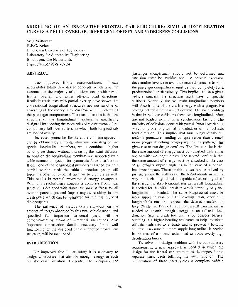
It is obvious that the rotating of the vehicle resulting in the velocity difference on both sides also has its influence on the decelerations. The same difference between both sides is found. At the beginning of the crash of the loaded longitudinal, the unloaded side is accelerated a little bit, see the negative deceleration in Figure 32.
100 30 degrees impact. 56 [km/h] (Sac 180-5)
- Vehicle centre / Left A-plllar
80 Right A-pillar I-\ J
-401 I 0 10 20 30 40 50 60 70
Time [ms]
Figure 32. Decelerations of a 30 degrees crash.
CONCLUSIONS
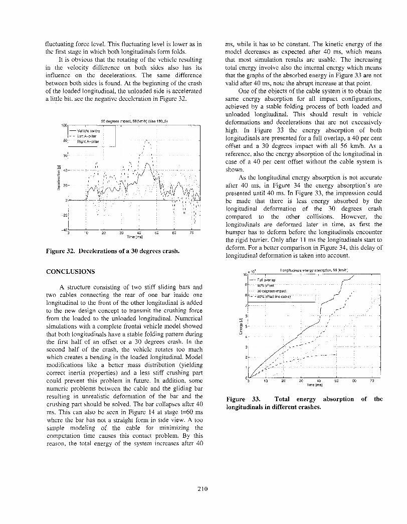
A structure consisting of two stiff sliding bars and two cables connecting the rear of one bar inside one longitudinal to the front of the other longitudinal is added to the new design concept to transmit the crushing force from the loaded to the unloaded longitudinal. Numerical simulations with a complete frontal vehicle model showed that both longitudinals have a stable folding pattern during the first half of an offset or a 30 degrees crash. In the second half of the crash, the vehicle rotates too much which creates a bending in the loaded longitudinal. Model modifications like a better mass distribution (yielding correct inertia properties) and a less stiff crushing part could prevent this problem in future. In addition, some numeric problems between the cable and the gliding bar resulting in unrealistic deformation of the bar and the crushing part should be solved. The bar collapses after 40 ms. This can also be seen in Figure 14 at stage t=60 ms where the bar has not a straight form in side view. A too simple modeling of the cable for minimizing the computation time causes this contact problem. By this reason, the total energy of the system increases after 40
ms, while it has to be constant. The kinetic energy of the model decreases as expected after 40 ms, which means that most simulation results are usable. The increasing total energy involve also the internal energy which means that the graphs of the absorbed energy in Figure 33 are not valid after 40 ms, note the abrupt increase at that point.
One of the objects of the cable system is to obtain the same energy absorption for all impact configurations, achieved by a stable folding process of both loaded and unloaded longitudinal. This should result in vehicle deformations and decelerations that are not excessively high. In Figure 33 the energy absorption of both longitudinals are presented for a full overlap, a 40 per cent offset and a 30 degrees impact with all 56 km/h. As a reference, also the energy absorption of the longitudinal in case of a 40 per cent offset without the cable system is shown.
As the longitudinal energy absorption is not accurate after 40 ms, in Figure 34 the energy absorption’s are presented until 40 ms. In Figure 33, the impression could be made that there is less energy absorbed by the longitudinal deformation of the 30 degrees crash compared to the other collisions. However, the longitudinals are deformed later in time, as first the bumper has to deform before the longitudinals encounter the rigid barrier. Only after 11 ms the longitudinals start to deform. For a better comparison in Figure 34, this delay of longitudinal deformation is taken into account.
Longltudlnals energy absorption. 56 [k&h]
z i r’ I F 5-
5 4- ,I
L: _’ -I
3- ’ ,’
-- -_ 2- ,’ _..-- , __
_’ i
_-- ---- I
0 0 10 20 30 40 50 60 70 Time [ms]
Figure 33. Total energy absorption of the longitudinals in different crashes.
210

6: s g 5- I: 4-
3- 2-
I-
O 0 5 10 15 20 25 30 35 ‘lo
Time [ms]
Figure 34. Energy absorption of the longitudinals in different crashes during 40 ms.
The conclusion can be drawn that using an advanced longitudinal design with cable system increases the energy absorption considerably in case of an offset and an oblique impact. However, the energy absorption is still less than the energy absorbed in a full overlap crash. For this difference, several reasons are mentioned. Another reason is of course the fact the unloaded longitudinal is loaded by the cable after the loaded longitudinal has formed one fold to prevent a peak load. It can be seen that the energy absorption’s of the offset and oblique crash initially stay below the energy absorption of the full overlap and after a few ms the difference remains relative constant for a longer time.
In Figure 35 the already showed deceleration levels of the full overlap, 40 per cent offset and the 30 degrees collision are combined in one picture as function of the deformation length instead of the normally used time axis. Again for a better comparison with the 30 degrees collision, for this crash situation a time correction of 11 ms resulting in 171 mm displacement is taken into account. Until 480 mm deformation (about 40 ms) the deceleration levels are accurate, after that time numerical instability occurs as already mentioned.
Figure 35. Comparison of the deceleration levels in three different crash situations.
Although the shape of the deceleration curves is sometimes whimsical, in several deformation intervals the level is similar. Figure 36 shows a more uniform course where the velocities are plotted against the deformation length. There is not so much difference in velocity decrease between the complete different collision situations (excluding the inaccurate end).
~ 100% overla - 40% overlap 1
30 dearee!
Figure 36. Comparison of the velocities in three different crash situations.
Further optimization of the numeric model is time consuming and cost a lot of computer time. This is at this moment not considered because the simulation results will always show deviations with a real crash. Reason is that many unknown factors like the final engine geometry and possible position and other not modeled parts have an influence on the crash behavior of the Iongitudinals.
211

Otherwise, adjustments in the structure are necessary to reach a wished deceleration level, which also depends on the final weight of the car. Main goal for these simulations is to show the designed system could work and despite all limitations, the difference in energy absorption between the most important crashes is considerably reduced. This is a very important result, because with this advanced design the same deceleration level of the car could be reached for each crash overlap percentage. Now it is possible to design a frontal car structure with one optimal stiffness that hardly varies for different crash situations. Hence, one optimal occupant deceleration level yielding the lowest injury levels is obtained over the entire collision spectrum.
REFERENCES
Beermann, H.J., Staisch, A., Aufpralluntersuchungen mit vereinfachenden Strukturmodellen. IV. IfF-Tagung, Braunschweig, 1982.
Landheer jr., D., Witteman, W.J., Kriens, R.F.C., Crashworthiness in the Concept Stage: A Parametric Body Design Method, FISITA paper B16.54, Prague, Czech Republic, 1996.
Leeuwen, O.L. van, Numerical Crashworthiness Design: Advanced Longitudinal Members in Frontal Vehicle Model. Master’s Thesis, Internal report WOCNT/R/97.47 Eindhoven University of Technology, Laboratory for Automotive Engineering, Eindhoven, 1997.
Slaats, P.M., Numerical Modelling and Crashworthiness Design of Vehicle Longitudinal Members. Master’s Thesis, Internal report WOCNT/R/96.04 Eindhoven University of Technology, Laboratory for Automotive Engineering, Eindhoven, 1996.
Wierzbicki, T.: Plastic Folding Wave and Effective Crush Distance. Center for Transportation Studies, M.I.T. Cambridge, MA, 021339.
Witteman, W.J.: Insufficiency of a Single Frontal Impact test for Vehicle Crashworthiness Assessment. Proceedings of the 261h ISATA Conference, Paper 93SF069, pp. 307- 314, Aachen, 1993.
Witteman, W.J., Kriens, R.F.C.: Crashworthiness Design of Longitudinal Members for Real Crash Situations. Proceedings of the Z?’ International EAEC Congress, Paper SIA 9506B13, Strasbourg, 1995.
Witteman, W.J., Kriens, R.F.C., A Cable-supported Frontal Car Structure for Offset Crash Situations. Proceedings of the Fifteenth ESV Conference, Paper 96-S3-W-24, pp. 55% 566, Melbourne, Australia, 1996.
Witteman, W.J., Kriens, R.F.C.: Requirements for Optimized Crashworthiness Design of the Longitudinal Members. Proceedings of the Fourteenth ESV Conference, Paper 94-S8-W-24, pp. 1481-1488, Munich, 1994.
212