mitral valve subvalvular apparatus repair with...
TRANSCRIPT

1
Mitral Valve Subvalvular Apparatus Repair with Artificial Neochords Application
Sergey Y. Boldyrev, Kirill O. Barbukhatty, Olga A. Rossokha and Vladimir A. Porhanov
Department of Adult Cardiac Surgery, Regional Clinic Hospital #1, Krasnodar, Kuban State Medical University, Krasnodar,
Russian Federation
1. Introduction
Degenerative mitral valve (МV) disease is a common disorder affecting around 2% of the population (Enriquez-Sarano M et al., 2009). The most common ending in patients with degenerative valve disease is leaflet rolapsed due to elongation or rupture of the chordal apparatus, resulting in varying degrees of МV regurgitation due to leaflet malcoaptation during ventricular contraction. The emphasis of clinical decision-making in patients with degenerative disease centres around the severity of regurgitation and its impact on symptom status, ventricular function and dimension, the sequelae of systolic flow reversal such as atrial dilatation/fibrillation and secondary pulmonary hypertension (PH), and the risk of sudden death (1-4). Current standard of care for MV rolapsed with severe mitral regurgitation (MR) is surgical MV repair (Adams et al., 2010). Implantation of neo-chordae with the use of expanded polytetrafluoroethylene (ePTFE) sutures (Gore Associates, Flagstaff, AZ, USA) has since its introduction into clinical practice by Frater et al. proven to be a valuable technique for contemporary MV repair. Chordal replacement enables preservation of native valve anatomy, physiological leaflet motion and creation of large mitral orifice area. Furthermore, it has contributed to the reparability independent of valve complexity (Seeburger et al., 2007).
2. Functional anatomy of the mitral valve
Historically, the mitral valve is described as composed of the leaflets, chordae, and papillary muscles. However, the mitral valve structurally and functionally is part of the left ventricle and intimately associated with the atrium and fibrous skeleton of the heart. Thus, alterations to the fibrous skeleton and ventricular and atrial muscle contribute to and affect valvular function.
2.1 Leaflets The leaflets are the valve component that creates the division between the atrium and ventricle. There are two distinct leaflets: the anterior or aortic and posterior or mural. The anterior leaflet is usually comprised of a single trapezoidal-shaped unit. The posterior leaflet is punctuated with multiple slits and clefts that define usually three, but up to six, distinct scallops (Fig. 1). The anterior and posterior leaflets are separated at the commissures but there is usually some continuity of the valve tissue close to the annulus. Further, if one looks
www.intechopen.com

Front Lines of Thoracic Surgery
4
at the chordal distribution, at the commissures, chordae are distributed to both leaflets from a common structural source—so the leaflets form a single functional unit. Nevertheless, it is useful for the purposes of valve repair to differentiate anterior from posterior. However, one must remember that multiple separately suspended distinct units come together to make the valve competent. To describe components of mitral valve repair it is useful to label the scallops by position (Fig. 1); posteriorly from left to right P1, P2, P3, with corresponding regions of the anterior leaflet A1, A2, and A3.
Fig. 1. Photograph of the mitral valve. Note multiple clefts in the posterior leaflet (arrows). The posterior leaflet is divided into 3 scallops or segments (lateral, middle, and medial scallops) identified as P1, P2, and P3. The corresponding segments of the anterior leaflet are labeled A1, A2, and A3.
When in the closed position, the orifice is obscured by the anterior and posterior leaflets. The anterior comprises about one half to two thirds of this area, the posterior comprises about one third to one half of this area. The point of attachment of the anterior leaflet comprises one third of the circumference of the annulus (the fibrous area) and the posterior leaflets comprises two thirds of the circumference of the annulus (the muscular area). The fibrous support of the anterior leaflet is fixed, the muscular support of the posterior leaflet can enlarge and does so when annular dilatation is associated with mitral regurgitation. The leaflets themselves are comprised of clear and rough zones. The clear zone is between the line of closure and the annulus and can be quite thin, almost transparent. The rough zone extends from the line of closure to the free edge, characterized by thicker, nodular ridges which promote sealing of the orifice on valve closure.
2.2 Annulus
Of the four heart valves, the mitral valve is the only valve that has a distinguishable annulus. However, the presence of a fibrous annular structure is variable and discontinuous. The firmest site of support for the mitral valve is the region of fibrous continuity between the aortic and mitral valves, the extent of which is delineated by the right and left fibrous trigones (Fig. 2). Nevertheless, for surgical purposes, the annulus is considered the area of attachment of the valve leaflets to the atrial muscle. The annulus is a functional component of the mitral valve. The annulus is quite flexible and changes shape throughout the cardiac cycle. With normal systolic function, the annulus will reduce in size by 20% to 40%. Functionally the mitral annulus is not two-dimensional but in fact three-dimensional assuming a saddle shape. The curvature imposed by the saddle shape reduces
www.intechopen.com

Mitral Valve Subvalvular Apparatus Repair with Artificial Neochords Application
5
mechanical stress on the leaflets. The curvature of the saddle shape or height of the “saddle horn” is reduced in a model of ischemic mitral regurgitation. This may have implications in choosing techniques for annular reduction and stabilization.
Fig. 2. Relational anatomy of the mitral valve: left and right fibrous trigones (LFT and RFT); anterior and posterior mitral leaflets (AL and PL); pulmonic, aortic, and tricuspid valves (PV, AV, and TV).
2.3 Tendinous chords
The tendinous chords, as functional extensions of the papillary muscles, perform the dual
function of maintaining valvular competence by preventing leaflet prolapse and
maintaining ventricular geometry by providing cross-ventricular support. The chords
originate from the apical portions of the papillary muscles or directly from the posterior
ventricular wall. They insert either into the free edge of the leaflets or on their ventricular
surface. Chords have been characterized a number of ways. The most useful for repair
purposes is to describe the first-degree chords as those inserting into the valve edge and the
second-degree chords as those inserting into the underside of the leaflet. Both first-degree
and second-degree chords originate from the papillary muscles and third-degree chords
originate from the ventricular wall and insert into the base of the posterior leaflet.
2.4 Papillary muscles
There are two papillary muscles associated with the mitral valve (Fig. 3) When looking from the atrial side, the anterolateral is to the left and the posteromedial is to the right. The muscles are located under their respective commissures. They originate from the lower third of the left ventricular free wall. The papillary muscles are extensions of the ventricular muscle from which they originate. The chords originate from the fibrous tips of these muscles, extending to insert on the mitral leaflets. The blood supply of the anterolateral papillary muscle derives from the left circumflex and/or diagonal systems. The blood supply of the posteromedial papillary muscle derives from the posterolateral coronary branches whether it originates from the left or right coronary system. The papillary muscles adjust tension and stabilize the valve during the cardiac cycle, rather than pulling the chords and leaflets into position. The function of the papillary muscles and their position is greatly dependent on the status of the ventricular myocardium underlying it. Displacement of the papillary muscle by distorted ventricular geometry is one mechanism for the creation of mitral regurgitation.
www.intechopen.com

Front Lines of Thoracic Surgery
6
Fig. 3. Mitral apparatus. ALPM, Anterolateral papillary muscle; PMPM, posteromedial papillary muscle; AoL, aortic leaflet; Ant.Com.L., anterior commissural leaflet; Post.Com.L., posterior commissural leaflet; Ant.Scal. , anterior scallop; Mid.Scal ., middle scallop; h, height of a leaflet; l, length of the attachment of a leaflet; Post.Scal. , posterior scallop; Rt. Trigone, right fibrous trigone; Lt. Trigone, left fibrous trigone; 1, anterior main chorda; 2, posterior main chorda; 3, anterior paramedial chorda; 4, posterior paramedial chorda; 5, anterior paracommissural chorda; 6, posterior paracommissural chorda; 7, anterior commissural chorda; 8, posterior commissural chorda; 9, anterior cleft chorda; 10, posterior cleft chorda.
3. Pathophysiology
Today, multiple terminologies used to describe mitral pathology. Terms such as prolapse, flail, partial flail, redundant, overshooting, stretching, elongation, floppy, billowing, ballooning, Barlow, dysplasia, myxoid, and myxomatous, for example, have different meanings for different specialists. The confusion comes first from the fact that several of these terms are synonyms. For example, flail leaflet, overshooting leaflet and leaflet prolapse are synonyms. Other synonyms are Barlow, billowing, ballooning, myxomatous valve, and mitral valve prolapse. Another source of confusion comes from the fact that for some specialists a given term such as « prolapse» means a disfunction (leaflet prolapsed) while for others it refers to a disease (mitral valve prolapse). The same chaotic situation applies to the term « floppy valve», which is used to define either a valve morphology, or dysfunction, or a disease. Similar confusion exists in tricuspid and aortic valve diseases, in which many of previously listed terms are used without clear distinction. Clarification can be obtained by using a pathophysiological triad with a sound distinction between the terms describing valve etiology (i.e., the cause of the disease), valve lesions resulting from the disease, and valve dysfunction resulting from the lesions.
Etiology - The cause of the disease ↓
Lesions - Result from the disease ↓
Dysfunction - Result from the lesions
The pathophysiological triad facilitates communication between cardiologists, echocardiographers and surgeons and greatly clarifies clinical investigation.
www.intechopen.com

Mitral Valve Subvalvular Apparatus Repair with Artificial Neochords Application
7
4. Etiology
Cardiac valves can be affected by numerous disease (Tab # 1). Primary valve disease involve the valvular tissue. Secondary valve disease affect the supporting of the valves – that is, the ventricles for the mitral and tricuspid valves and the aorta and pulmonary artery for the aortic and pulmonary valves, respectively. The determination of the etiology of valvular disease is important because it helps to establish the medical treatment, which should precede or follow valve reconstruction.
Primary valve Disease• Congenital malformation • Inflammatory disease
Rheumatic Lupus erythematoses Valve sclerosis
• Degenerative disease Barlow, s disease Marfan,s disease Fibroelastic deficiency
• Infective endocarditis • Valvular or annular calcification • Trauma • Valvular tumors
Secondary to Myocardial Disease • Ischemic cardiomyopathy • Dilated cardiomyopathy • Hypertrophic obstructive
cardiomyopathy • Myocardial sarcoidosis • Endomyocardial fibrosis • Myocardial tumors
Table 1. Etiology of valvular disease.
5. Lesions
Any of the previously listed disease can cause lesions affecting one or several components of the heart valves: the annulus, the leaflets, and the supporting structures (Table #2).
Mitral\ Tricuspid ValvesAnnular dilatation Leaflet perforation Leaflet tear Leaflet thickening Vegetations Commissure fusion Calcification Chordae rupture Chordae elongation Chordae thickening Chordae fusion Papillary muscle rupture Papillary muscle elongation Ventricular aneurysm Ventricular fibrous plaque Ventricular dilatation
Aortic\Pulmonary ValvesAnnular dilatation Leaflet perforation Leaflet distension Vegetations Commissure detachment Commissure fusion Calcification Sino-tubular dilatation
Table 2. Valvular Lesions.
www.intechopen.com

Front Lines of Thoracic Surgery
8
6. Valve dysfunction: The «Functional classification»
The pioneering cardiac surgeon Alain Carpentier, MD, PhD, developed a functional classification to reflect the underlying pathological changes that contributed to MR (Carpentier A. 1983) (Figure 4). As described in this classification, type I MR is characterized as normal leaflet motion but with annular dilatation or leaflet perforation; type II lesions are related to leaflet prolapse and may be caused by myxomatous disease, such as chord rupture or elongation, or by papillary muscle rupture or elongation; and type III lesions are caused by restricted leaflet motion. Type IIIA is typically caused by rheumatic valve disease with normal ventricular motion and subvalvular fibrosis and calcification; type IIIB is typically caused by ischemic or idiopathic cardiomyopathy with impaired ventricular function and dilation but a “normal” morphology to the leaflets, chords, and papillary muscles, frequently with restriction at the P3 segment. Type I MR may occur with billowing myxomatous leaflets but without elongated chordae and prolapse (type II), if extensive annular dilatation leads to inadequate leaflet coaptation (Fornes P et al., 1999).
Fig. 4. Functional classification.
7. Degenerative valvular disease
The tree main types of degenerative valvular disease are Barlow,s disease, fibroelastoc deficiency, and Marfan,s disease.
7.1 Myxomatous mitral valve disease (Barlow’s disease)
Barlow’s disease is the most frequent degenerative valvular disease with a prevalence of 4% to 5 % in the general population, generally appears early in life. Patients present with a prolonged history of a murmur, thickened leaflets, substantial excess tissue, and a dilated annulus, which may be calcified (1). Chordae may be elongated and thinned. Often isolated ruptures are present, contributing to the focal prolapse. Classically, the most common abnormality is focal enlargement of the posterior central scallop (P2) with an associated ruptured chorda. Mills et al. comparing unileaflet versus bileaflet prolapse, found that patients with unileaflet prolapse were younger and had a higher incidence of flail leaflets (3). Patients with bileaflet prolapse were less likely to be hypertensive and had mechanically stronger chordae though leaflet strength was similar to patients with unileaflet prolapse.
www.intechopen.com

Mitral Valve Subvalvular Apparatus Repair with Artificial Neochords Application
9
7.2 Marfan’s disease
Marfan's syndrome of the mitral valve is characterized by excess tissue, thickened leaflets, and a dilated annulus. Patients with Marfan syndrome have a shortened life expectancy because of cardiovascular complication, 80% of them developing mitral valve regurgitation.
7.3 Fibroelastic deficiency
Fibroelastic deficiency occurs mostly in the elderly with a short history of valvular dysfunction. The leaflets are transparent, and except for the prolapsing segment there is no excess tissue. The chordae are thin, fragile, and elongated. The annulus is dilated and often infiltrated with calcium (Table #3).
Table 3. Кеу differences between Barlow,s disease and fibroelastic deficiency
7.4 Pathologic anatomy of degenerative mitral valve disease
According to A. Marc Gillinov and coworkers, pathologic anatomy of degenerative mitral valve disease is presented in group of 1072 patients as follows (Table #4).
Table 4. Pathologic anatomy of degenerative mitral valve disease (n = 1072).
www.intechopen.com

Front Lines of Thoracic Surgery
10
8. Surgical treatment
8.1 Principles of valve reconstruction
Guided by functional valve analysis, the surgeon should indentify all the lesions. The
ultimate aim of valve reconstruction is to restore durable normal valve function. Three basic
conditions are required to achieve this goal: preserving or restoring normal leaflet motion of
all valve segments, creating a large surface of leaflet coaptation, remodeling the mitral valve
orifice. Ideally correct application of repair techniques will produce appropriate coaptation.
The rough zones of the leaflet should be in contact. The ratio of leaflet surface area to valve
orifice area should be corrected to its natural 2:1 ratio. Because annular dilatation is a
component of chronic mitral regurgitation, some type of annular support is necessary.
Annuloplasty often completes the repair but cannot compensate for an inadequate repair.
Echocardiography with color flow and spectral Doppler evaluation is an important
noninvasive method for assessing the significance of cardiac murmurs. Information
regarding valve morphology and function, chamber size, wall thickness, ventricular
function, pulmonary and hepatic vein flow, and estimates of pulmonary artery pressures
can be readily integrated. Zoghbi et al., 2003 presented qualitative and quantitative
parameters useful in grading mitral regurgitation severity (Table#5).
Table 5. Qualitative and quantitative parameters useful in grading mitral regurgitation severity.
Three different MV operations are currently used for correction of MR: 1) MV repair; 2) MV
replacement with preservation of part or all of the mitral apparatus; and 3) MV replacement
www.intechopen.com

Mitral Valve Subvalvular Apparatus Repair with Artificial Neochords Application
11
with removal of the mitral apparatus. Each procedure has its advantages and disadvantages,
and therefore, the indications for each procedure are somewhat different (Bonow et al.,
2008).
In most cases, MV repair is the operation of choice when the valve is suitable for repair
and appropriate surgical skill and expertise are available. This procedure preserves the
patient’s native valve without a prosthesis and therefore avoids the risk of chronic
anticoagulation (except in patients in atrial fibrillation) or prosthetic valve failure late
after surgery. Additionally, preservation of the mitral apparatus leads to better
postoperative LV function and survival than in cases in which the apparatus is disrupted.
Improved postoperative function occurs with repair because the mitral apparatus is an
integral part of the left ventricle that is essential for maintenance of normal shape,
volume, and function of the left ventricle. However, MV repair is technically more
demanding than MV replacement, may require longer extracorporeal circulation time,
and may occasionally fail. In USA (Savage et al., 2003) and Europe (Lung et al., 2003) the
valve with MV regurgitation is repaired in only 50% of cases. Valve morphology and
surgical expertise are of critical importance for the success of valve repair. The
reoperation rate after MV repair is similar to the reoperation rate after MV replacement.
There is a 7% to 10% reoperation rate at 10 years in patients undergoing MV repair,
usually for severe recurrent MR. Approximately 70% of the recurrent MR is thought to be
due to the initial procedure and 30% to progressive valve disease. The reoperation rate is
lower in those patients who had the initial operation for posterior leaflet abnormalities
than in those who had bileaflet or anterior leaflet abnormalities. In many cases, the type of
operation, MV repair versus replacement, is important in timing surgery. In fact, although
the type of surgery to be performed is never actually established until the operation,
many situations lend themselves to preoperative prediction of the operation that can be
performed. This prediction is based on the skill and experience of the surgeon in
performing repair and on the location and type of MV disease that caused the MR.
Nonrheumatic posterior leaflet prolapse due to degenerative MV disease or a ruptured
chordae tendineae can usually be repaired using a resection of the portion of the valve
and an annuloplasty. Involvement of the anterior leaflet or both anterior and posterior
leaflets diminishes the likelihood of repair because the operation requires other
interventions, such as chordal shortening, chordal transfer, and innovative anatomic
repairs. Consequently, the skill and experience of the surgeon are probably the most
important determinants of the eventual operation that will be performed.
8.2 Surgical approach
According to M. Scorsin (Scorsin et al., 2010), in 90% cases of posterior mitral valve prolapse
is repaired with standart techniques: 1 - quadrangular \ triangular resection + placation of
annulus, sliding, folding; 2- artificial chordate sutures. Current techniques for anterior
leaflet prolapsed include valvular and subvalvular approach. In turn, valvular approach
include papillary muscle placation, chordal shortening, leaflet resection, transposition of
chordate. Subvalvular approach include artificial chordate. Among several repair techniques
chordal replacement using ePTFE sutures has been introduced into clinical practise by
Frater. There are several advantages to use of ePTFE suture for chordal replacement -
preservation of native valve anatomy, physiological leaflet motion and creation of large
www.intechopen.com

Front Lines of Thoracic Surgery
12
mitral orifice area. Properly inserted, ePTFE sutures restore stress on the valve leaflet to a
normal range. Long-term studies in experimental animals and in humans show that ePTFE
chordae do not shrink or stiffen; indeed, these artificial chordae become covered by a
fibrosis and intima simulating true chordae.
8.3 Evolution of modern valve repair techniques with artificial chordae
Medical literature describes numerous techniques to create and to determine ideal length
for artificial chordae. Bizzarri et al has analysed evolution of modern valve repair
techniques with artificial chordae (Bizzarri et al., 2010). Morita et al., 1996 were the first
to use 4-0 PTFE figure of 8 to repair both leaflets prolapse passing from the papillary body
to the leaflet and back adding a Kay annuloplasty at the end of the procedure. Zussa,
1997, one of the pioneers of this technique, repaired an anterior leaflet with PTFE strings
passing through the head of the papillary muscle and tying over a reinforcing autologous
pericardial pledget. The strings were then anchored to the free margin of the anterior
mitral leaflet at the unsupported areas and reinforced with a small autologous pericardial
pledget. The two strands were tied after filling the ventricular cavity with saline solution
for adjusting the chordal length. Murakami et al., 1998 approached the anterior leaflet
prolapse using mattress e-PTFE suture with Teflon or autologous pledget passed through
the free margin of the leaflet from the ventricular side to the atrial side. The two arms of
the suture, reinforced with pledgets, were brought down to the papillary muscle and
passed through it. The length of the e-PTFE chordae was then adjusted by approximating
the coapting area of the opposite leaflet and the ends of the sutures were then tied
together (Figure 5).
Fig. 5.
www.intechopen.com

Mitral Valve Subvalvular Apparatus Repair with Artificial Neochords Application
13
Chordae tendinae reconstruction, in patients with prolapsed of anterior leaflet was done
by Matsumoto et al., 1999 in children using the following technique: double-armed
mattress e-PTFE sutures were passed through the free prolapsed edge from the
ventricular side to the atrial side and then the two ends were passed through the papillary
muscle at 3 to 4 mm from its top, drawing the free edge down to the entry point on the
papillary muscle of the two ends of the suture. The sutures were passed through a
pledget, which would be on the side where the sutures emerged from the papillary
muscle. The knot was tied at the level of the opposing normal leaflet. The new chorda was
pulled back through the papillary muscle until the pledget came up against the muscle.
Another e-PTFE suture was placed in the same fashion. A Kay-Reed annuloplasty was
added (Figure 6).
Fig. 6.
Kawahira et al., 1999 used 4-0 e-PTFE sutures through the prolapsed leaflet from its
ventricular to atrial aspect, placing pledgets for reinforcement on the ventricular surface of
the leaflet. The sutures were anchored to the papillary muscles in a mattress fashion. This
maneuver could be carried out in reverse order: attaching e- PTFE suture initially to the
papillary muscle, subsequently passing it through the leaflet from it's ventricular to atrial
aspect. In this circumstance, the knot would be placed on the atrial aspect of the mitral
valve. Adams et al., 2001 placed one or more 4-0 Gore- Tex sutures into the head of the
papillary muscle. Papillary muscle exposure was enhanced after quadrangular posterior
leaflet resection. Before annuloplasty poor leaflet apposition is present in all leaflet segments
with saline testing and segmental anterior leaflet prolapse is best identified by height
comparison with a normal reference point. After ring annuloplasty symmetric leaflet
apposition limits leaflet incompetence to the prolapsing anterior leaflet segment. Both arms
of the previously placed Gore-Tex suture are passed through the margin of the prolapsing
leaflet segment. Passing the suture through the free edge of the cusp twice as well as starting
with a surgeon's knot are techniques to prevent overaggressive sliding of the knots when
tying the Gore-Tex suture (Figure 7).
www.intechopen.com
Front Lines of Thoracic Surgery
14
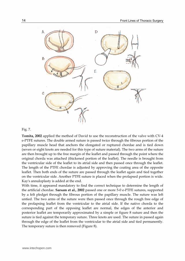
Fig. 7.
Tomita, 2002 applied the method of David to use the reconstruction of the valve with CV-4
e-PTFE sutures. The double armed suture is passed twice through the fibrous portion of the
papillary muscle head that anchors the elongated or ruptured chordae and is tied down
(seven or eight knots are needed for this type of suture material). The two arms of the suture
are then brought up to the free margin of the leaflet and passed through the point where the
original chorda was attached (thickened portion of the leaflet). The needle is brought from
the ventricular side of the leaflet to its atrial side and then passed once through the leaflet.
The length of the PTFE chordae is adjusted by approving the coating area of the opposite
leaflet. Then both ends of the suture are passed through the leaflet again and tied together
on the ventricular side. Another PTFE suture is placed when the prolapsed portion is wide.
Kay's annuloplasty is added at the end.
With time, it appeared mandatory to find the correct technique to determine the length of
the artificial chordae. Sarsam et al., 2002 passed one or more 5-0 e-PTFE sutures, supported
by a felt pledget through the fibrous portion of the papillary muscle. The suture was left
untied. The two arms of the suture were then passed once through the rough free edge of
the prolapsing leaflet from the ventricular to the atrial side. If the native chorda to the
corresponding part of the opposing leaflet are normal, the edges of the anterior and
posterior leaflet are temporarily approximated by a simple or figure 8 suture and then the
suture is tied against the temporary suture. Three knots are used. The suture in passed again
through the edge of the leaflet from the ventricular to the atrial side and tied permanently.
The temporary suture is then removed (Figure 8).
www.intechopen.com

Mitral Valve Subvalvular Apparatus Repair with Artificial Neochords Application
15
Fig. 8.
Soga, 2003 made a resection of both the anterior and posterior mitral leaflets and subvalvular apparatus and placed two 3-0 e-PTFE mattress sutures: one placed and tied at the tip of the anterior papillary muscle, and one at the tip of the posterior papillary muscle. The suture of the anterior PM is placed at the 9-10 o'clock position on the mitral annulus (as defined by mid-anterior annulus to be 0 o'clock), and the suture for the posterior PM at the 5-6 o'clock. According to the authors, the length of the artificial CT can be determined during intraoperative cardiac arrest, and may be suitable if the sutures are tied just less than taut before insertion of the prosthetic. After the valve replacement, the motion of the prosthetic leaflets is examined to ensure that the leaf let are not entrapped by the 3-0 e-PTFE sutures (Figure 9).
Fig. 9.
www.intechopen.com

Front Lines of Thoracic Surgery
16
Tomita, 2005 repaired chordae tendinae with CV-4 e-PTFE sutures. Double armed sutures are passed twice through the fibrous portion of the PM head that anchors the elongated or ruptured chordae and are tied down (7 or 8 knots are needed for this suture material). The two arms of the suture are brought up to the free margin of the leaflet and passed through the point where the original chorda was attached (thickened portion of the leaflet). The needle is brought from the ventricular side of the leaflet to its atrial side and passed once more through the leaflet. The length of PTFE chordae is adjusted by referring the contact area of the opposite leaflet and then both ends of the suture are passed through the leaflet again and tied together on the ventricular side. When the prolapsed portion became wide, another PTFE suture was placed in the same fashion. At the end Kay's suture annuloplasty (n = 24) or ring annuloplasty was performed. Minami, 2005 used double armed mattress sutures of 4-0, 5- 0 or 6-0 e-PTFE placed to reinforce with felt pledgets between the PM and free margin of the anterior leaflet. The length of the PTFE sutures was adjusted with the adjacent normal anterior leaflet or facing posterior leaflet. When the prolapsed portion became wide, another suture was placed in the same fashion. The number of sutures ranged from 1 to 3. In addition, Kay annuloplasty was perfomed. Matsui, 2005 employed a new device (Matsuda Ika-Kogyo, Tokyo, Japan) consisting of two metallic tubes with a circular, hook shaped distal tip made entirely of stainless steel. The distal tip, which is perpendicularly attached to the inner tube, was designed to hold the Gore-Tex thread at the reference point on the PM immovable. The outer tube could slide on the surface of the inner tube to measure the length from the tip of inner tube to the hook of outer tube. A 4-0 or 5-0 Gore-Tex mattress suture, reinforced with a felt pledget, was placed into the head of the PM. Both arms of the suture where left untied. Length was determined by measuring the distance between the leaflet edge and the site of implantation of the artificial chordae on the PM, using a normal valve segment adjacent to the prolapsing segment as a reference. The distal tip of the inner tube of the device was placed at the sutured site of the artificial chordae on the PM. The proximal hook of the outer tube was slid to the edge of the adjacent non prolapsing leaflet and then fixed at that point after reading the distance between the distal tip and proximal hook to the device. Devices were then moved to the prolapsed segments so as to hold an edge of the prolapsed leaflet with a proximal hook. As the determined distance and edge of the leaflet were fixed with the device, the Gore-Tex suture could be tied in the usual manner without knot slipping. The action of knot-tying itself works to immobilize the device by its strength. After removing the device, followed by saline testing, a Carpenter- Edwards annuloplasty ring was attached according to the size of the mitral annulus (Figure 10).
Fig. 10.
www.intechopen.com

Mitral Valve Subvalvular Apparatus Repair with Artificial Neochords Application
17
Prêtre et al., 2006 applied the artificial chordae to the mitral valve using an approach
through the aortic valve for an anterior and posterior leaflet prolaps. In the anterior repair
an atriotomy was performed first, the artificial chordae was placed in the usual manner, and
then a flexible annular ring was tied on the mitral annulus. An aortotomy was performed to
expose the native chordae and to calibrate the length of the artificial chordae that were
locked but not tied down. The mitral valve was inspected through the atriotomy while
saline water was injected through the aortotomy in the left ventricle. The chordae were tied
from the aortotomy and the incisions closed in the usual fashion. In the posterior leaflet
prolapse, repair was done and a ring was inserted using a classical atrial incision. The
ascending aorta was opened and the artificial chordae were set on the papillary muscles and
the anterior leaflet was calibrated. The valve was re-inspected through the atriotomy with
instillation of saline in the left ventricle for adjusting the chordae until they were definitively
secured Figure 11.
Fig. 11.
Lawrie et al., 2006 published their experience on 152 consecutive patients. 5-0 PTFE sutures
were placed into the bases of the papillary muscles in a figure-8 fashion, and were brought
through the free edge of the prolapsing segment. Dots were made to mark the desired final
line of leaflet apposition. The left ventricle was inflated with saline solution and the chordal
length was adjusted to align the edges of the leaflets. Leaflet alignment was checked and the
PTFE was tied down. The knot was locked with a 6-0 polypropylene stitch which was tied
over the end of the PTFE to prevent sliding of the PTFE knots. An annuloplasty ring was
then implanted.
Calafiore, 2006 in the anterior leaflet prolapse passed 4-0 PTFE sutures through the fibrous
tip of the papillary muscle and fixed the sutures. The new chorda was passed in the border
of the anterior leaflet in the proper place and its final length was measured with a ruler. A
mark was applied to indicate this distance and the suture was tied with the aid of a nerve
hook (Figure 12).
www.intechopen.com

Front Lines of Thoracic Surgery
18
Fig. 12.
Rankin, 2006 in the anterior and/or posterior leaflet prolapsed placed 4-0 prolene pledgetted horizontal mattress sutures longitudinally into each papillary muscle, passing one arm through the fibrous tip, and tying firmly; through this anchor suture, a double-armed Gortex suture was passed but not tied. A Carpentier annuloplasty ring was sutured. With the ring in position, the chordae were retrieved from the ventricle, and both needles were woven into the prolapsing segment, straddling the point of maximal prolapse. Two or three bites were taken through the coaptation surface to the line of coaptation. The two arms of the suture were tied on the atrial surface with a slip-knot to bring the leaflet to the annular plane, and a clip was placed across the knot. Pericardial pledgets could be used if the leaflet tissue seems fragile. Cold saline solution was infused to check the length of the suture; once the valve was competent, eight more knot were tied tightly against the clip, the suture was cut, and the clip was removed (Figure 13).
Fig. 13.
Tam, 2006 used the following technique for any prolapsing segment. A calliper was used to measure the length of the reference chordae. A 4-0 ePTFE suture was used to create loops around the calliper. Non-sliding knots were placed at the end of each loop while still on the calliper. After making a desired number of loops, the needles were passed through the loops and tied. Two needles at the end of the sutures were passed through an ePTFE pledget,
www.intechopen.com

Mitral Valve Subvalvular Apparatus Repair with Artificial Neochords Application
19
which was now ready to be secured to the papillary muscle. The ePTFE chordae were secured at the tip of the papillary muscle with two pledgets and attached to the edge of the prolapsing mitral leaflet using eight 5-0 ePTFE sutures (Figure 14).
Fig. 14.
Mandegar, 2007 for any leaflet prolapse used following technique. During preoperative transesophageal echocardiography, a line was drawn between the base of the anterior and posterior mitral leaflet to measure the distance between the head of the posterior papillary muscle and the plane at the co-optation of the leaflets; this measured the artificial chordal length. During surgery, 4-0 Gore- Tex was passed through the fibrous tip of the papillary muscle with a pledget and was fixed with a loose knot. Two tight reverse knots were made for every millimeter of 4-0 Gore-Tex that was required. The needles were passed through the edge of the anterior leaflet at the prolapsing portion, and the Gore-Tex was knotted onto a strip of pericardium so that the final knot could be placed at the atrial side of the leaflet (Figure 15).
Fig. 15.
www.intechopen.com

Front Lines of Thoracic Surgery
20
Gillinov, 2007 describe a technique for reparing anterior leaflet prolapse. Chordal length
was determined with a calliper, and ePTFE chordae were constructed making loops around
it. A pledget was used to prepare the number of 5-0 ePTFE loops that were needed. When all
chordal loops were constructed, each needle was passed through the head of the papillary
muscle, and was affixed to the free edge of the anterior leaflet with a figure 8 suture of CV-5
ePTFE (Figure 16).
Fig. 16.
Scorsin et al., 2007: any leaflet prolapse. Artificial chordae system device was composed of 2
sets of 4 artificial chordae, attached to a 3-mm strip of knitted polyester 18 mm wide, leaving
4 mm between each chorda. The device was applied by suturing the strip to the free edge of
the prolapsed leaflet by continuous suture. Each array was anchored to the tip of the
correspondent papillary muscle by only one stitch. After this procedure, a prosthetic
annuloplasty ring was inserted (Figure 17).
Fig. 17.
Maselli and De Paulis, 2007 used a novel system to repair the valve consisting of two
components: leaflet component and the papillary component. The first one was achieved
with a CV-5 PTFE suture. A circular loop was obtained at the middle of the suture by tying
it around a Hegar dilator with a diameter of 13 mm. Flattened loop's length should equals
www.intechopen.com
Mitral Valve Subvalvular Apparatus Repair with Artificial Neochords Application
21
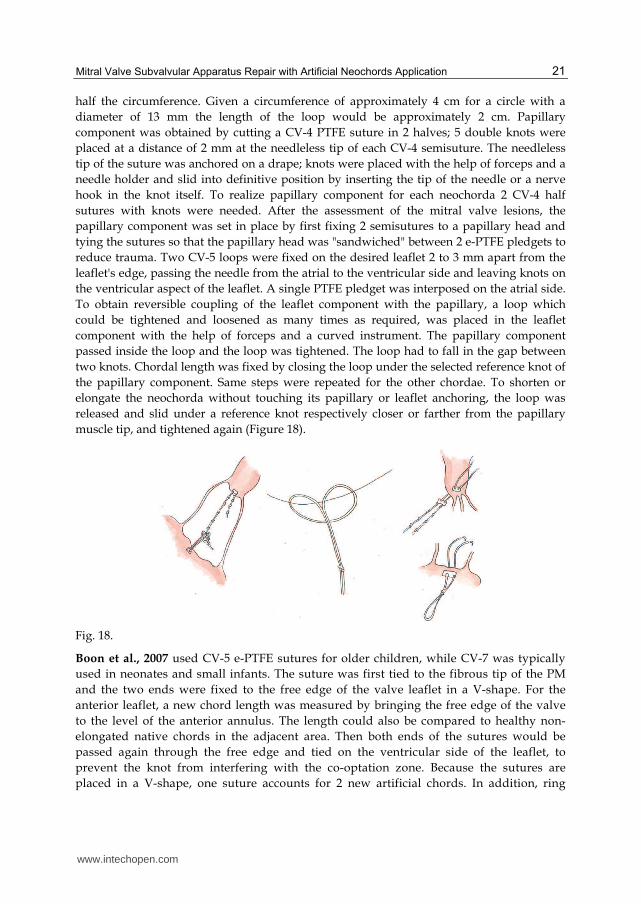
half the circumference. Given a circumference of approximately 4 cm for a circle with a
diameter of 13 mm the length of the loop would be approximately 2 cm. Papillary
component was obtained by cutting a CV-4 PTFE suture in 2 halves; 5 double knots were
placed at a distance of 2 mm at the needleless tip of each CV-4 semisuture. The needleless
tip of the suture was anchored on a drape; knots were placed with the help of forceps and a
needle holder and slid into definitive position by inserting the tip of the needle or a nerve
hook in the knot itself. To realize papillary component for each neochorda 2 CV-4 half
sutures with knots were needed. After the assessment of the mitral valve lesions, the
papillary component was set in place by first fixing 2 semisutures to a papillary head and
tying the sutures so that the papillary head was "sandwiched" between 2 e-PTFE pledgets to
reduce trauma. Two CV-5 loops were fixed on the desired leaflet 2 to 3 mm apart from the
leaflet's edge, passing the needle from the atrial to the ventricular side and leaving knots on
the ventricular aspect of the leaflet. A single PTFE pledget was interposed on the atrial side.
To obtain reversible coupling of the leaflet component with the papillary, a loop which
could be tightened and loosened as many times as required, was placed in the leaflet
component with the help of forceps and a curved instrument. The papillary component
passed inside the loop and the loop was tightened. The loop had to fall in the gap between
two knots. Chordal length was fixed by closing the loop under the selected reference knot of
the papillary component. Same steps were repeated for the other chordae. To shorten or
elongate the neochorda without touching its papillary or leaflet anchoring, the loop was
released and slid under a reference knot respectively closer or farther from the papillary
muscle tip, and tightened again (Figure 18).
Fig. 18.
Boon et al., 2007 used CV-5 e-PTFE sutures for older children, while CV-7 was typically
used in neonates and small infants. The suture was first tied to the fibrous tip of the PM
and the two ends were fixed to the free edge of the valve leaflet in a V-shape. For the
anterior leaflet, a new chord length was measured by bringing the free edge of the valve
to the level of the anterior annulus. The length could also be compared to healthy non-
elongated native chords in the adjacent area. Then both ends of the sutures would be
passed again through the free edge and tied on the ventricular side of the leaflet, to
prevent the knot from interfering with the co-optation zone. Because the sutures are
placed in a V-shape, one suture accounts for 2 new artificial chords. In addition, ring
www.intechopen.com

Front Lines of Thoracic Surgery
22
annuloplasty or Wooler-Kay bilateral commissural plication annuloplasty was performed.
Chan, 2008: for anterior leaflet prolapse a 4-0 Gore-Tex suture with pledgets was used.
The suture was first passed through the papillary muscle and secured with 6 to 8 knots.
Both braids were then passed through the prolapsed leaflet edge no more than 4 mm
apart. The suture was then tensed up. The non-prolapsing posterior leaflet was used to
check the reference length. A single-arm rubber- protected artery forceps was clipped on
the mark, and knots were tied on it.
Salvador, 2008: for anterior leaflet prolapse repair a e-PTFE double-armed suture (GORE-
TEX CV-5) were passed through the PM with a mattress technique and reinforced with
autologous pericardial pledgets (rarely, GORE-TEX pledgets), on both sides of the muscle.
Each end of the suture were fixed to the free margin of the prolapsed leaflet and
reinforced with a small autologous pericardial pledget or a small GORE-TEX pledget. The
length of the artificial chordae was adjusted to maintain the corresponding free margin of
the leaflet at the desired level in the ventricular cavity. To determine the correct length of
the artificial chordae, the neochordae were tied at the end of all the other repair
procedures after the ventricular cavity is filled with saline solution. Smith and Stein, 2008
made the first endoscopic placement of multiple pre-measured artificial chordae with
Robotic assistance and nitinol clip fixation. Robotic bileaflet mitral valve repair used a
more lateral approach and 5 right thoracoscopic ports, ranging in size from 8 to 20 mm.
Left atriotomy was perform to expose mitral valve using a robotically controlled
EndoWrist atrial retractor (Intuitive Surgical Inc.). The prolapsing segment was identified
with valve hooks. The "ski-tip" style ends of the robotic retractor blades are longed into
the anterior leaflet, then the atrial septum is lifted to visualize PM. The length of the
artificial chordae loops were determined with the measure of the distance between the
correct plane of apposition on an adjacent normal non-prolapsing segment of the mitral
leaflet and the respective PM (done with a More Suture Ruler device). Artificial chordae,
with 4 loops each, were constructed of 4-0 PTFE GORE-TEX per the technique by von
Oppel and Mohr. A single felt pledget constructed the platform with multiple neochords
of definite length extending from its base. Both free suture needles from the pledget
platform were passed through the respective PM with 2 robotic large needle drivers. After
the correct placement in the muscle head, the needles were retrieved and the neochordae
platform was secured with extracorporeal knots tied by the assistant using a closed knot
pusher. Each neochordae loop was attached to the edge of the prolapsing leaflet by
applying a single-armed V60 U-clip per loop. The singlearmed U-clip was placed in the
leaflet edge with a robotic large needle holder and the neochordae loop was captured in
the open clip circle. The U-clip was deployed by pulling the needle off the clip portion,
securing the neochordae loop to the leaflet. Additional reduction of the leaflet height
could be achieved by folding the leaflet edge toward the ventricle before deploying the U-
clip. The remaining loops were distributed at equal distance along the edge of the
prolapsed segment by applying the same technique. After the pledget platform was
secured, the 2 free suture needles were placed through the anterior prolapse. The correct
apposition was confirmed with saline test. The assistan, at the patient side, tied the knots.
Annuloplasty was performed at the surgeon's discretion. For concomitant left atrial
ablation a SurgiFlex XL probe was applied endocardially. Lastly the heart was de-aired
and the left atrium was closed with a running suture line ( Figure 19).
www.intechopen.com

Mitral Valve Subvalvular Apparatus Repair with Artificial Neochords Application
23
Fig. 19.
Doi, 2009 measured the length of the chordae of the posterior leaflet, opposing the
prolapsing portion of the anterior leaflet by TEE. The length of chordae was a measurement
of the distance between the head of the PM and the free edge of the posterior leaflet. Length
of the opposing chordae of the posterior leaflet was measured directly by using a calliper.
Double-armed mattress sutures with CV-5 GORE-TEX were placed at the fibrous tip of the
PM using PTFE on both sides and tied down firmly. In all cases Doi performed Duran ring
annuloplasty. Thereafter, the ePTFE suture is placed through the anterior leaflet. The
needles were passed through the rough zone of the prolapsing portion from the atrial to the
ventricular side, and again through the free margin of the leaflet from the ventricular to the
atrial side. The caliper that was fixed at the length of the opposing chordae was inserted
inside the loop created by the ePTFE suture. The suture was easily tied at the exact length of
the opposing chordae and the anterior leaflet was fixed at the height of the posterior leaflet
(Figure 20).
Fig. 20.
The main difference between the techniques is in the measurement of the length of the
artificial chordae. The oldest and most common method to calibrate the length of the neo-
chordae consists in filling the left ventricular cavity with saline solution. Other authors
elongated the prosthetic chordae trying to approximate the coaptation area between the two
mitral leaflets. Recently, a variety of different calipers that allow in some manner to check
the length and to tighten the number of necessary chordae have been introduced to better
define the adequacy of the PTFE chordae implantation.
www.intechopen.com

Front Lines of Thoracic Surgery
24
8.4 New device
In our Cardiothoracic Surgery Center we worked out our own device to measure proper
length of chords and multiple loops formation (Figure 21).
Fig. 21. Boldyrev – Barbukhatty- Porhanov device.
The gist of the given model is that on the end of the working body we placed props located perpendicularly to the plane of the graduated scale and fitted with circular cuttings for loop fixation, and on a scale there is a core clamp.By means of our appliance one is able to perform at the same time intraoperative measurement of the chordal apparatus and to generate necessary quantity of loops for chord prosthetic repair. This device is in process of patenting in the Russian Federation (request № 2011101697\14(002183), January 18, 2011)
8.5 South Russian experience
Material and Methods: From 2008 to 2011 we have treated 30 patients with moderately
severe (3+) or severe (4+) mitral regurgitation. Echocardiographic findings are showed in
the Table 6.
MV regurgitation grade by color Doppler 3 ± 0,44
Regurgitation volume, ml 109 ± 19,4
MV EF,% 57 ± 5,4
Left atrium size, mm 51,4 ± 6,8
Left ventricular end diastolic dimension, mm 60,9 ± 5,2
Left ventricular end diastolic volume, ml 199,5 ± 38,4
LV EF, % 49,2 ± 8,5
Pulmonary hypertension, mm Hg 49,2 ± 8,5
Table 6. Preoperative echocardiographic data.
They all underwent MV chord system repair. There were 17 male and 13 female patients. Age range was from 16 to 70 years (mean age 55,3 ± 13). Mean ejection fraction was 49%, and minimal - 35% (3 cases). Etiology 20 (66%) patient had fibroelastoc deficiency, 2 (7%) - ischemic heart disease, 3 ( 10%) had Barlow,s disease, 2 (7%) had Marfan,s disease, and 3 (10%) had mitral valve malformation. 7 (23%) patients were found to have posterior leaflet
www.intechopen.com

Mitral Valve Subvalvular Apparatus Repair with Artificial Neochords Application
25
prolapse, 5 (17%) patients – bileaflet prolapse, and 18 (60%) – anterior leaflet prolapse. We performed 7 posterior mitral valve leaflet chord reconstructions, in 4 cases with multiple loops. Anterior mitral leaflet chord repair was carried out in 18 (60%) patients (including multiple loops in 10 cases). 5 (17%) patient had total AML chord repair ( Figure 22, 23).
Fig. 22. Patient Ch. Preoperative echocardiography (left, two-chambered position at the
mitral valve level) and postoperative view (right, four-chambered position).
Fig. 23. Patient Ch. Intraoperative photo total anterior mitral leaflet chord repair.
www.intechopen.com

Front Lines of Thoracic Surgery
26
1(3%) patient underwent total chordae replacement (anterior and posterior leaflets). We
applied quadrangular resection with leaflet height adjustment of posterior leaflet for
bileaflet prolapses with AMV chord repair. When we carried out repair with multiple loops
we used a device (proper modification) to measure length and formation of neochords. To
make multiple loops we followed the sequence showed in Figure 24.
Fig. 24. Scheme of multiple loops performance (from A to E).
All patients underwent suturing annuloplasty or were implanted supporting rings MedIng.
Results: All patients survived. Operative results were assessed by echocardiography (Table 7).
MV regurgitation grade by color Doppler 1,14 ± 0,8
Regurgitation volume, ml 20 ± 11,8
MV EF,% 20 ± 11,8
Left atrium size, mm 42,6 ± 4,2
Left ventricular end diastolic dimension, mm 51,8 ± 7,4
Left ventricular end diastolic volume, ml 51,8 ± 7,4
LV EF, % 54,6 ± 9,6
Pulmonary hypertension, mm Hg 34,8 ± 7,1
Table 7. Postoperative echocardiographic data.
www.intechopen.com
Mitral Valve Subvalvular Apparatus Repair with Artificial Neochords Application
27
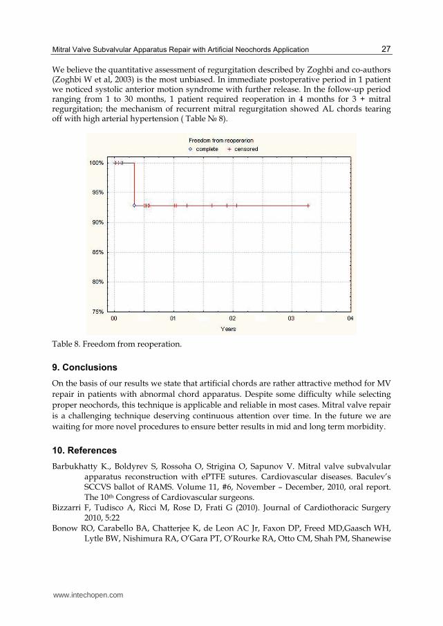
We believe the quantitative assessment of regurgitation described by Zoghbi and co-authors (Zoghbi W et al, 2003) is the most unbiased. In immediate postoperative period in 1 patient we noticed systolic anterior motion syndrome with further release. In the follow-up period ranging from 1 to 30 months, 1 patient required reoperation in 4 months for 3 + mitral regurgitation; the mechanism of recurrent mitral regurgitation showed AL chords tearing off with high arterial hypertension ( Table № 8).
Table 8. Freedom from reoperation.
9. Conclusions
On the basis of our results we state that artificial chords are rather attractive method for MV
repair in patients with abnormal chord apparatus. Despite some difficulty while selecting
proper neochords, this technique is applicable and reliable in most cases. Mitral valve repair
is a challenging technique deserving continuous attention over time. In the future we are
waiting for more novel procedures to ensure better results in mid and long term morbidity.
10. References
Barbukhatty К., Boldyrev S, Rossoha О, Strigina О, Sapunov V. Mitral valve subvalvular apparatus reconstruction with ePTFE sutures. Cardiovascular diseases. Baculev’s SCCVS ballot of RAMS. Volume 11, #6, November – December, 2010, oral report. The 10th Congress of Cardiovascular surgeons.
Bizzarri F, Tudisco A, Ricci M, Rose D, Frati G (2010). Journal of Cardiothoracic Surgery 2010, 5:22
Bonow RO, Carabello BA, Chatterjee K, de Leon AC Jr, Faxon DP, Freed MD,Gaasch WH, Lytle BW, Nishimura RA, O’Gara PT, O’Rourke RA, Otto CM, Shah PM, Shanewise
www.intechopen.com

Front Lines of Thoracic Surgery
28
JS. 2008 focused update incorporated into the ACC/AHA 2006 guidelines for the management of patients with valvular heart disease: a report of the American College of Cardiology/American Heart Association Task Force on Practice Guidelines (Writing Committee to revise the 1998 guidelines for the management of patients with valvular heart disease). Endorsed by the Society of Cardiovascular Anesthesiologists, Society for Cardiovascular Angiography and Interventions, and Society of Thoracic Surgeons. J AmColl Cardiol 2008;52:e1–e142.
Carpentier A.; Adams D; Filsoufi F. (2010). Carpentier's Reconstructive Valve Surgery, Elsevier, ISBN: 978-0-7216-9168-8 USA
Savage E; Bolling S, (2006). Atlas of Mitral Valve Repair, Lippincott Williams & Wilkins, ISBN – 13:978-0-7817-4692-2 USA
www.intechopen.com

Front Lines of Thoracic SurgeryEdited by Dr. Stefano Nazari
ISBN 978-953-307-915-8Hard cover, 412 pagesPublisher InTechPublished online 03, February, 2012Published in print edition February, 2012
InTech EuropeUniversity Campus STeP Ri Slavka Krautzeka 83/A 51000 Rijeka, Croatia Phone: +385 (51) 770 447 Fax: +385 (51) 686 166www.intechopen.com
InTech ChinaUnit 405, Office Block, Hotel Equatorial Shanghai No.65, Yan An Road (West), Shanghai, 200040, China
Phone: +86-21-62489820 Fax: +86-21-62489821
Front Lines of Thoracic Surgery collects up-to-date contributions on some of the most debated topics intoday's clinical practice of cardiac, aortic, and general thoracic surgery,and anesthesia as viewed by authorspersonally involved in their evolution. The strong and genuine enthusiasm of the authors was clearlyperceptible in all their contributions and I'm sure that will further stimulate the reader to understand theirmessages. Moreover, the strict adhesion of the authors' original observations and findings to the evidencebase proves that facts are the best guarantee of scientific value. This is not a standard textbook where thewhole discipline is organically presented, but authors' contributions are simply listed in their pertainingsubclasses of Thoracic Surgery. I'm sure that this original and very promising editorial format which has andfree availability at its core further increases this book's value and it will be of interest to healthcareprofessionals and scientists dedicated to this field.
How to referenceIn order to correctly reference this scholarly work, feel free to copy and paste the following:
Sergey Y. Boldyrev, Kirill O. Barbukhatty, Olga A. Rossokha and Vladimir A. Porhanov (2012). Mitral ValveSubvalvular Apparatus Repair with Artificial Neochords Application, Front Lines of Thoracic Surgery, Dr.Stefano Nazari (Ed.), ISBN: 978-953-307-915-8, InTech, Available from:http://www.intechopen.com/books/front-lines-of-thoracic-surgery/mitral-valve-subvalvular-apparatus-repair-with-artificial-neochords-application