micom p341 - ge grid solutions · pdf filemicom p341 (ad) -5 output contacts standard contacts...
TRANSCRIPT
MiCOM P341
Update Documentation
Interconnection Protection Relay
Platform Hardware Version: J
Platform Software Version: 33
Publication Reference: P341/EN AD/F53
P341/EN AD/F53 © 2011. ALSTOM, the ALSTOM logo and any alternative version thereof are trademarks and service marks of ALSTOM. The other names
mentioned, registered or not, are the property of their respective companies. The technical and other data contained in this document is provided for information only.
Neither ALSTOM, its officers or employees accept responsibility for, or should be taken as making any representation or warranty (whether express or implied), as to
the accuracy or completeness of such data or the achievement of any projected performance criteria where these are indicated. ALSTOM reserves the right to revise or
change this data at any time without further notice.
GRID

Update Documentation P341/EN AD/F53 MiCOM P341
UPDATE DOCUMENTATION
Date: 16th July 2008
Hardware Suffix: J
Software Version: 33
Connection Diagrams: 10P341xx (xx = 01 to 04)

P341/EN AD/F53 Update Documentation
MiCOM P341
Update Documentation P341/EN AD/F53 MiCOM P341
(AD) -1
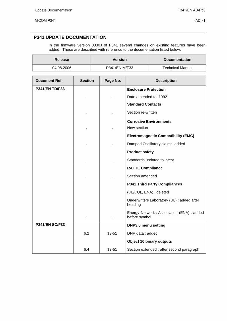
P341 UPDATE DOCUMENTATION
In the firmware version 0330J of P341 several changes on existing features have been added. These are described with reference to the documentation listed below:
Release Version Documentation
04.08.2006 P341/EN M/F33 Technical Manual
Document Ref. Section Page No. Description
P341/EN TD/F33
- -
Enclosure Protection
Date amended to: 1992
- -
Standard Contacts
Section re-written
- -
Corrosive Environments
New section
- -
Electromagnetic Compatibility (EMC)
Damped Oscillatory claims: added
- -
Product safety
Standards updated to latest
- -
R&TTE Compliance
Section amended
- -
P341 Third Party Compliances
(UL/CUL, ENA) : deleted
Underwriters Laboratory (UL) : added after heading
Energy Networks Association (ENA) : added before symbol
P341/EN SC/F33
6.2 13-51
DNP3.0 menu setting
DNP data : added
6.4 13-51
Object 10 binary outputs
Section extended : after second paragraph

P341/EN AD/F53 Update Documentation (AD) -2
MiCOM P341
Document Ref. Section Page No. Description
6.5 13-52
Object 20 binary counters
First paragraph : extended
6.6 13-52
Object 30 analog input
First paragraph : amended
P341/EN SC/F33 continued
6.7 13-52
Object 40 analog output
New section
6.71 13-52
Object 1
Section deleted
6.7.2 13-53
Object 20
Section deleted
6.7.3 13-53
Object 30
Section deleted
6.8 13-52
DNP3.0 configuration using MiCOM S1 studio
Heading title: amended
First paragraph : amended and separated into two paragraphs
P341/EN VH/F33
- 1-33
Firmware and service manual version history
Updated to reflect latest relay software

Update Documentation P341/EN AD/F53 MiCOM P341
(AD) -3
TECHNICAL DATA (P341/EN TD/F33)
Technical Data
Mechanical Specifications
Design Modular MiCOM Px40 platform relay, P341 in 40TE case. Mounting is front of panel flush mounting, or 19“ rack mounted with rack frame (ordering options).
Enclosure Protection Per IEC 60529: 1992: IP 52 Protection (front panel) against dust and dripping water, IP 50 Protection for sides of the case, IP 10 Protection for the rear.
Weight P341 (40TE) :7kg
Terminals
AC Current and Voltage Measuring Inputs Located on heavy duty (black) terminal block: Threaded M4 terminals, for ring lug connection. CT inputs have integral safety shorting, upon removal of the terminal block.
General Input/Output Terminals For power supply, opto inputs, output contacts and RP1 rear communications. Located on general purpose (grey) blocks: Threaded M4 terminals, for ring lug connection.
Case Protective Earth Connection Two rear stud connections, threaded M4. Must be earthed (grounded) for safety, minimum earth wire size 2.5mm2.
Front Port Serial PC Interface EIA(RS)232 DCE, 9 pin D-type female connector Socket SK1. Courier protocol for interface to MiCOM S1 Studio software. Isolation to ELV (extra low voltage) level. Maximum cable length 15m.
Front Download/Monitor Port EIA(RS)232, 25 pin D-type female connector Socket SK2. For firmware and menu text downloads. Isolation to ELV level.
Rear Communications Port (RP1) EIA(RS)485 signal levels, two wire connections located on general purpose block, M4 screw. For screened twisted pair cable, multidrop, 1000m max. For K-Bus, IEC-60870-5-103, MODBUS or DNP3.0 protocol (ordering options). Isolation to SELV (safety extra low low voltage) level.
Optional Rear Fiber Connection for SCADA/DCS BFOC 2.5 -(ST®)-interface for glass fiber, as per IEC 874-10. 850nm short-haul fibers, one Tx and one Rx. For Courier, IEC-60870-5-103, MODBUS or DNP3.0 (Ordering options).
Optional Second Rear Communications Port (RP2) EIA(RS)232, 9 pin D-type female connector, socket SK4. Courier protocol: K-Bus, EIA(RS)232, or EIA(RS)485 connection. Isolation to SELV level.
Optional Rear IRIG-B Interface modulated or de-modulated BNC plug Isolation to SELV level. 50 ohm coaxial cable.
Optional Rear Ethernet Connection for IEC 61850
10BaseT/100BaseTX Communications Interface in accordance with IEEE802.3 and IEC 61850 Isolation: 1.5kV Connector type: RJ45 Cable type: Screened Twisted Pair (STP) Max. cable length: 100m
100 Base FX Interface Interface in accordance with IEEE802.3 and IEC 61850 Wavelength: 1300nm Fiber: multi-mode 50/125µm or 62.5/125µm Connector type: BFOC 2.5 - (ST®)
P341/EN AD/F53 Update Documentation (AD) -4
MiCOM P341
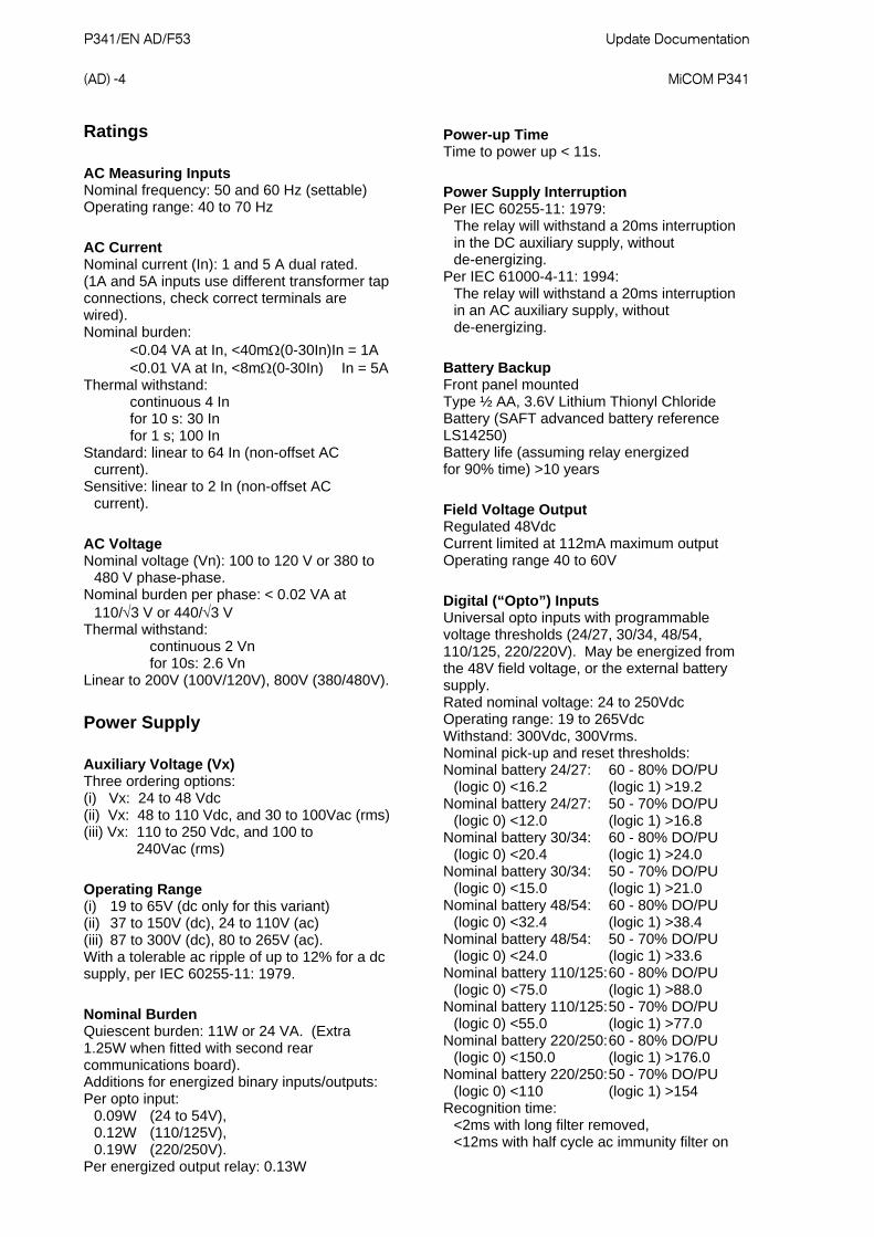
Ratings
AC Measuring Inputs Nominal frequency: 50 and 60 Hz (settable) Operating range: 40 to 70 Hz
AC Current Nominal current (In): 1 and 5 A dual rated. (1A and 5A inputs use different transformer tap connections, check correct terminals are wired). Nominal burden: <0.04 VA at In, <40m(0-30In)In = 1A <0.01 VA at In, <8m(0-30In) In = 5A Thermal withstand: continuous 4 In for 10 s: 30 In for 1 s; 100 In Standard: linear to 64 In (non-offset AC current). Sensitive: linear to 2 In (non-offset AC current).
AC Voltage Nominal voltage (Vn): 100 to 120 V or 380 to 480 V phase-phase. Nominal burden per phase: < 0.02 VA at 110/3 V or 440/3 V Thermal withstand: continuous 2 Vn for 10s: 2.6 Vn Linear to 200V (100V/120V), 800V (380/480V).
Power Supply
Auxiliary Voltage (Vx) Three ordering options: (i) Vx: 24 to 48 Vdc (ii) Vx: 48 to 110 Vdc, and 30 to 100Vac (rms) (iii) Vx: 110 to 250 Vdc, and 100 to 240Vac (rms)
Operating Range (i) 19 to 65V (dc only for this variant) (ii) 37 to 150V (dc), 24 to 110V (ac) (iii) 87 to 300V (dc), 80 to 265V (ac). With a tolerable ac ripple of up to 12% for a dc supply, per IEC 60255-11: 1979.
Nominal Burden Quiescent burden: 11W or 24 VA. (Extra 1.25W when fitted with second rear communications board). Additions for energized binary inputs/outputs: Per opto input: 0.09W (24 to 54V), 0.12W (110/125V), 0.19W (220/250V). Per energized output relay: 0.13W
Power-up Time Time to power up < 11s.
Power Supply Interruption Per IEC 60255-11: 1979:
The relay will withstand a 20ms interruption in the DC auxiliary supply, without de-energizing.
Per IEC 61000-4-11: 1994: The relay will withstand a 20ms interruption in an AC auxiliary supply, without de-energizing.
Battery Backup Front panel mounted Type ½ AA, 3.6V Lithium Thionyl Chloride Battery (SAFT advanced battery reference LS14250) Battery life (assuming relay energized for 90% time) >10 years
Field Voltage Output Regulated 48Vdc Current limited at 112mA maximum output Operating range 40 to 60V
Digital (“Opto”) Inputs Universal opto inputs with programmable voltage thresholds (24/27, 30/34, 48/54, 110/125, 220/220V). May be energized from the 48V field voltage, or the external battery supply. Rated nominal voltage: 24 to 250Vdc Operating range: 19 to 265Vdc Withstand: 300Vdc, 300Vrms. Nominal pick-up and reset thresholds: Nominal battery 24/27: 60 - 80% DO/PU (logic 0) <16.2 (logic 1) >19.2 Nominal battery 24/27: 50 - 70% DO/PU (logic 0) <12.0 (logic 1) >16.8 Nominal battery 30/34: 60 - 80% DO/PU (logic 0) <20.4 (logic 1) >24.0 Nominal battery 30/34: 50 - 70% DO/PU (logic 0) <15.0 (logic 1) >21.0 Nominal battery 48/54: 60 - 80% DO/PU (logic 0) <32.4 (logic 1) >38.4 Nominal battery 48/54: 50 - 70% DO/PU (logic 0) <24.0 (logic 1) >33.6 Nominal battery 110/125: 60 - 80% DO/PU (logic 0) <75.0 (logic 1) >88.0 Nominal battery 110/125: 50 - 70% DO/PU (logic 0) <55.0 (logic 1) >77.0 Nominal battery 220/250: 60 - 80% DO/PU (logic 0) <150.0 (logic 1) >176.0 Nominal battery 220/250: 50 - 70% DO/PU (logic 0) <110 (logic 1) >154 Recognition time: <2ms with long filter removed, <12ms with half cycle ac immunity filter on
Update Documentation P341/EN AD/F53 MiCOM P341
(AD) -5
Output Contacts
Standard Contacts General purpose relay outputs for signaling, tripping and alarming: Rated voltage: 300 V Continuous current: 10 A Short-duration current: 30 A for 3 s Making capacity: 250A for 30 ms Breaking capacity: DC: 50W resistive DC: 62.5W inductive (L/R = 50ms) AC: 2500VA resistive (cos = unity) AC: 2500VA inductive (cos = 0.7) AC: 1250VA inductive (cos = 0.5) Subject to maxima of 10A and 300V Response to command: < 5ms Durability: Loaded contact: 10 000 operations
minimum, Unloaded contact: 100 000 operations
minimum.
Standard Contacts General purpose relay outputs for signaling, tripping and alarming: Continuous Carry Ratings (Not Switched): Maximum continuous current: 10A (UL: 8A) Short duration withstand carry: 30A for 3s 250A for 30ms Rated voltage: 300 V
Make & Break Capacity: DC: 50W resistive DC: 62.5W inductive (L/R = 50ms) AC: 2500VA resistive (cos = unity) AC: 2500VA inductive (cos = 0.7) Make, Carry: 30A for 3 secs, dc resistive, 10,000 operations (subject to the above limits of make / break capacity and rated voltage) Make, Carry & Break: 30A for 200ms, ac resistive, 2,000 operations (subject to the above limits of make / break capacity & rated voltage) 4A for 1.5 secs, dc resistive, 10,000 operations (subject to the above limits of make / break capacity & rated voltage) 0.5A for 1 sec, dc inductive, 10,000 operations (subject to the above limits of make / break capacity & rated voltage) 10A for 1.5 secs, ac resistive / inductive, 10,000 operations (subject to the above
limits of make / break capacity & rated voltage)
Durability: Loaded contact: 10 000 operations minimum, Unloaded contact: 100 000 operations minimum.
Operate Time Less than 5ms Reset Time Less than 5ms
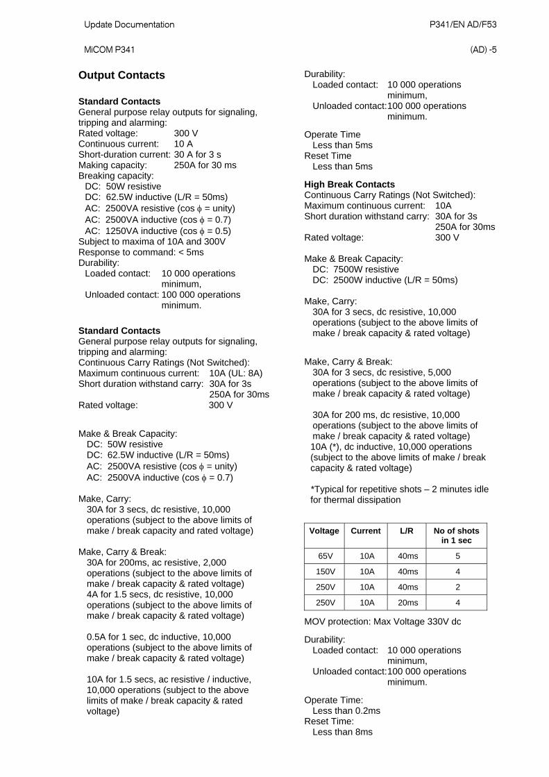
High Break Contacts Continuous Carry Ratings (Not Switched): Maximum continuous current: 10A Short duration withstand carry: 30A for 3s 250A for 30ms Rated voltage: 300 V Make & Break Capacity: DC: 7500W resistive DC: 2500W inductive (L/R = 50ms) Make, Carry: 30A for 3 secs, dc resistive, 10,000 operations (subject to the above limits of make / break capacity & rated voltage)
Make, Carry & Break: 30A for 3 secs, dc resistive, 5,000 operations (subject to the above limits of make / break capacity & rated voltage) 30A for 200 ms, dc resistive, 10,000 operations (subject to the above limits of make / break capacity & rated voltage)
10A (*), dc inductive, 10,000 operations (subject to the above limits of make / break capacity & rated voltage)
*Typical for repetitive shots – 2 minutes idle for thermal dissipation
Voltage Current L/R No of shots
in 1 sec
65V 10A 40ms 5
150V 10A 40ms 4
250V 10A 40ms 2
250V 10A 20ms 4
MOV protection: Max Voltage 330V dc
Durability: Loaded contact: 10 000 operations minimum, Unloaded contact: 100 000 operations minimum.
Operate Time: Less than 0.2ms Reset Time: Less than 8ms
P341/EN AD/F53 Update Documentation (AD) -6
MiCOM P341
Watchdog Contacts Non-programmable contacts for relay healthy/relay fail indication: Breaking capacity: DC: 30W resistive DC: 15W inductive (L/R = 40ms) AC: 375VA inductive (cos = 0.7)
IRIG-B Interface (Modulated) External clock synchronization per IRIG standard 200-98, format B12x Input impedance 6k at 1000Hz Modulation ratio: 3:1 to 6:1 Input signal, peak-peak: 200mV to 20V
IRIG-B 00X Interface (De-modulated) External clock synchronization per IRIG standard 200-98, format B00X. Input signal TTL level Input impedance at dc 10k
Environmental Conditions
Ambient Temperature Range Per IEC 60255-6: 1988: Operating temperature range: -25°C to +55°C (or -13°F to +131°F) Storage and transit: -25°C to +70°C (or -13°F to +158°F)
Ambient Humidity Range Per IEC 60068-2-3: 1969: 56 days at 93% relative humidity and +40 °C Per IEC 60068-2-30: 1980
Damp heat cyclic, six (12 + 12) hour cycles, 93% RH, +25 to +55 °C
Corrosive Environments Per IEC 60068-2-60: 1995, Part 2, Test Ke, Method (class) 3 Industrial corrosive environment/poor environmental control, mixed gas flow test. 21 days at 75% relative humidity and +30oC exposure to elevated concentrations of H2S, NO2, Cl2 and SO2.
Type Tests
Insulation Per IEC 60255-27: 2005 Insulation resistance > 100M at 500Vdc (Using only electronic/brushless insulation tester).
Creepage Distances and Clearances IEC 60255-27: 2005 Pollution degree 3, Overvoltage category III, Impulse test voltage 5 kV.
High Voltage (Dielectric) Withstand (i) Per IEC 60255-27: 2005, 2 kV rms AC, 1 minute: Between all independent circuits. Between independent circuits and protective (earth) conductor terminal.
1kV rms AC for 1 minute, across open watchdog contacts. 1kV rms AC for 1 minute, across open contacts of changeover output relays. 1kV rms AC for 1 minute for all D-type EIA(RS)232/EIA(RS)485 ports between the communications port terminals and protective (earth) conductor terminal.
(ii) Per ANSI/IEEE C37.90-1989 (reaffirmed 1994): 1.5 kV rms AC for 1 minute, across open contacts of normally open output relays. 1kV rms AC for 1 minute, across open watchdog contacts. 1kV rms AC for 1 minute, across open contacts of changeover output relays.
Impulse Voltage Withstand Test Per IEC 60255-27: 2005 Front time: 1.2 µs, Time to half-value: 50 µs, Peak value: 5 kV, 0.5J Between all independent circuits. Between all independent circuits and protective (earth) conductor terminal. Between the terminals of independent circuits. EIA(RS)232 & EIA(RS)485 ports and normally open contacts of output relays excepted.
Electromagnetic Compatibility (EMC)
1 MHz Burst High Frequency Disturbance Test Per IEC 60255-22-1: 1988, Class III, Common-mode test voltage: 2.5 kV, Differential test voltage: 1.0 kV, Test duration: 2 s, Source impedance: 200 (EIA(RS)232 ports excepted).
100kHz Damped Oscillatory Test Per EN61000-4-18: 2007: Level 3 Common mode test voltage: 2.5kV Differential mode test voltage: 1kV
Update Documentation P341/EN AD/F53 MiCOM P341
(AD) -7
Immunity to Electrostatic Discharge Per IEC 60255-22-2: 1996, Class 4,
15kV discharge in air to user interface, display, communication port and exposed metalwork.
6kV point contact discharge to any part of the front of the product.
Electrical Fast Transient or Burst Requirements Per IEC 60255-22-4: 2002 and EN61000-4-4:2004. Test severity Class III and IV: Amplitude: 2 kV, burst frequency 5kHz (Class III), Amplitude: 4 kV, burst frequency 2.5kHz (Class IV). Applied directly to auxiliary supply, and applied to all other inputs. (EIA(RS)232 ports excepted). Amplitude: 4 kV, burst frequency 5 kHz (Class IV) applied directly to auxiliary.
Surge Withstand Capability Per IEEE/ANSI C37.90.1: 2002: 4kV fast transient and 2.5kV oscillatory
applied directly across each output contact, optically isolated input, and power supply circuit.
4kV fast transient and 2.5kV oscillatory applied common mode to communications,
IRIG-B.
Surge Immunity Test (EIA(RS)232 ports excepted). Per IEC 61000-4-5: 2005 Level 4, Time to half-value: 1.2 / 50 µs,
Amplitude: 4kV between all groups and protective (earth) conductor terminal. Amplitude: 2kV between terminals of each group.
Immunity to Radiated Electromagnetic Energy Per IEC 60255-22-3: 2000, Class III: Test field strength, frequency band 80 to 1000 MHz: 10 V/m, Test using AM: 1 kHz / 80%, Spot tests at 80, 160, 450, 900 MHz Per IEEE/ANSI C37.90.2: 2004: 80MHz to 1000MHz, 1kHz 80% AM and AM pulsed modulated. Field strength of 35V/m.
Radiated Immunity from Digital Communications Per EN61000-4-3: 2002, Level 4: Test field strength, frequency band 800 to 960 MHz, and 1.4 to 2.0 GHz:
30 V/m, Test using AM: 1 kHz/80%.
Radiated Immunity from Digital Radio Telephones Per IEC61000-4-3: 2002: 10 V/m, 900MHz and 1.89GHz.
Immunity to Conducted Disturbances Induced by Radio Frequency Fields Per IEC 61000-4-6: 1996, Level 3, Disturbing test voltage: 10 V.
Power Frequency Magnetic Field Immunity Per IEC 61000-4-8: 1994, Level 5, 100A/m applied continuously, 1000A/m applied for 3s. Per IEC 61000-4-9: 1993, Level 5, 1000A/m applied in all planes. Per IEC 61000-4-10: 1993, Level 5,
100A/m applied in all planes at 100kHz/1MHz with a burst duration of 2s.
Conducted Emissions Per EN 55022: 1998 Class A:
0.15 - 0.5MHz, 79dBV (quasi peak) 66dBV (average) 0.5 - 30MHz, 73dBV (quasi peak) 60dBV (average).
Radiated Emissions Per EN 55022: 1998 Class A:
30 - 230MHz, 40dBV/m at 10m measurement distance 230 - 1GHz, 47dBV/m at 10m measurement distance.
EU Directives
EMC Compliance Per 2004/108/EC: Compliance to the European Commission Directive on EMC is demonstrated using a Technical File. Product Specific Standards were used to establish conformity: EN50263: 2000
Product Safety Per 2006/95/EC: Compliance to the European Commission Low Voltage Directive. (LVD) is demonstrated using a Technical File. A product specific standard was used to establish conformity. EN 60255-27: 2005
P341/EN AD/F53 Update Documentation (AD) -8
MiCOM P341
R&TTE Compliance P341 THIRD PARTY COMPLIANCES Radio and Telecommunications Terminal Equipment (R & TTE) directive 99/5/EC. Underwriters Laboratory (UL) Compliance demonstrated by compliance to both the EMC directive and the Low voltage directive, down to zero volts.
Applicable to rear communications ports.
File Number: E202519 Original Issue Date: 05-10-2002
ATEX Compliance ATEX Potentially Explosive Atmospheres directive 94/9/EC, for equipment. (Complies with Canadian and US
requirements). The equipment is compliant with Article 1(2) of European directive 94/9/EC.
Energy Networks Association (ENA) It is approved for operation outside an ATEX hazardous area. It is however approved for connection to Increased Safety, “Ex e”, motors with rated ATEX protection, Equipment Category 2, to ensure their safe operation in gas Zones 1 and 2 hazardous areas.
Certificate Number: 104 Issue 2 Assessment Date: 16-04-2004
CAUTION - Equipment with this marking is not itself suitable for operation within a potentially explosive atmosphere. Compliance demonstrated by Notified Body certificates of compliance.
II (2) G
Mechanical Robustness
Vibration Test Per IEC 60255-21-1: 1996: Response Class 2 Endurance Class 2
Shock and Bump Per IEC 60255-21-2: 1996: Shock response Class 2 Shock withstand Class 1 Bump Class 1
Seismic Test Per IEC 60255-21-3: 1995: Class 2
Update Documentation P341/EN AD/F53 MiCOM P341
(AD) -9
SCADA COMMUNICATIONS (P341/EN SC/F33)
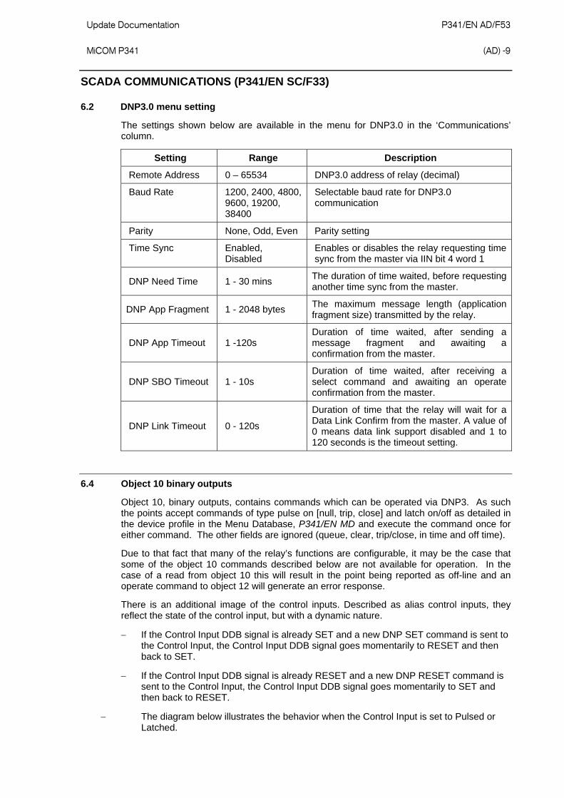
6.2 DNP3.0 menu setting
The settings shown below are available in the menu for DNP3.0 in the ‘Communications’ column.
Setting Range Description
Remote Address 0 – 65534 DNP3.0 address of relay (decimal)
Baud Rate 1200, 2400, 4800, 9600, 19200, 38400
Selectable baud rate for DNP3.0 communication
Parity None, Odd, Even Parity setting
Time Sync Enabled, Disabled
Enables or disables the relay requesting time sync from the master via IIN bit 4 word 1
DNP Need Time 1 - 30 mins The duration of time waited, before requesting another time sync from the master.
DNP App Fragment 1 - 2048 bytes The maximum message length (application fragment size) transmitted by the relay.
DNP App Timeout 1 -120s Duration of time waited, after sending a message fragment and awaiting a confirmation from the master.
DNP SBO Timeout 1 - 10s Duration of time waited, after receiving a select command and awaiting an operate confirmation from the master.
DNP Link Timeout 0 - 120s
Duration of time that the relay will wait for a Data Link Confirm from the master. A value of 0 means data link support disabled and 1 to 120 seconds is the timeout setting.
6.4 Object 10 binary outputs
Object 10, binary outputs, contains commands which can be operated via DNP3. As such the points accept commands of type pulse on [null, trip, close] and latch on/off as detailed in the device profile in the Menu Database, P341/EN MD and execute the command once for either command. The other fields are ignored (queue, clear, trip/close, in time and off time).
Due to that fact that many of the relay’s functions are configurable, it may be the case that some of the object 10 commands described below are not available for operation. In the case of a read from object 10 this will result in the point being reported as off-line and an operate command to object 12 will generate an error response.
There is an additional image of the control inputs. Described as alias control inputs, they reflect the state of the control input, but with a dynamic nature.
If the Control Input DDB signal is already SET and a new DNP SET command is sent to the Control Input, the Control Input DDB signal goes momentarily to RESET and then back to SET.
If the Control Input DDB signal is already RESET and a new DNP RESET command is sent to the Control Input, the Control Input DDB signal goes momentarily to SET and then back to RESET.
The diagram below illustrates the behavior when the Control Input is set to Pulsed or Latched.

P341/EN AD/F53 Update Documentation (AD) -10
MiCOM P341
DNP Latch ON
DNP Latch ON
DNP Latch OFF
DNP Latch OFF
'Behaviour of Control InputsExisting with Pulsed/Latched SettingAliased Control Inputs with Pulsed/Latched SettingNote: The pulse width is equal to the duration of one protectioniteration (½ cycle for P341 and ¼ cycle for P342/3/4/5)'
Control Input (Latched)
Aliased Control Input
(Latched)
Control Input (Pulsed)
Aliased Control Input
( Pulsed)
Figure 8: Behaviour of control inputs
Examples of object 10 points that maybe reported as off-line are:
Activate setting groups - Ensure setting groups are enabled
CB trip/close - Ensure remote CB control is enabled
Reset NPS thermal - Ensure NPS thermal protection is enabled
Reset thermal O/L - Ensure thermal overload protection is enabled
Reset RTD flags - Ensure RTD Inputs is enabled
Control inputs - Ensure control inputs are enabled
6.5 Object 20 binary counters
Object 20, binary counters, contains cumulative counters and measurements. The binary counters can be read as their present ‘running’ value from object 20, or as a ‘frozen’ value from object 21. The running counters of object 20 accept the read, freeze and clear functions. The freeze function takes the current value of the object 20 running counter and stores it in the corresponding object 21 frozen counter. The freeze and clear function resets the object 20 running counter to zero after freezing its value. Binary counter and frozen counter change event values are available for reporting from object 22 and object 23 respectively. Counter change events (object 22) only report the most recent change, so the maximum number of events supported is the same as the total number of counters. Frozen counter change events (object 23) are generated when ever a freeze operation is performed and a change has occurred since the previous freeze command. The frozen counter event queues will store the points for up to two freeze operations.
Update Documentation P341/EN AD/F53 MiCOM P341
(AD) -11
6.6 Object 30 analogue input
Object 30, analog inputs, contains information from the relay’s measurements columns in the menu. All object 30 points can be reported as 16 or 32 bit integer values with flag, 16 or 32 bit integer without flag as well as short floating-point values. Analogue values can be reported to the master station as primary, secondary or normalized values (which takes into account the relay’s CT and VT ratios) and this is settable in the DNP3.0 Communications Column in the relay. Corresponding deadband settings can be displayed in terms of a primary, secondary or normalized value. Deadband point values can be reported and written using Object 34 variations. The deadband is the setting used to determine whether a change event should be generated for each point. The change events can be read via object 32 or object 60 and will be generated for any point whose value has changed by more than the deadband setting since the last time the data value was reported.
Any analog measurement that is unavailable at the time it is read will be reported as offline, for example the frequency when the current and voltage frequency is outside the tracking range of the relay or the thermal state when the thermal protection is disabled in the configuration column.
6.7 Object 40 analogue output
The conversion to fixed-point format requires the use of a scaling factor, which is configurable for the various types of data within the relay for example current, voltage, phase angle etc. All Object 40 points report the integer scaling values and Object 41 is available to configure integer scaling quantities.
6.8 DNP3.0 configuration using MiCOM S1 Studio
A PC support package for DNP3.0 is available as part of the Settings and Records module of MiCOM S1 Studio. The S1 module allows configuration of the relay’s DNP3.0 response. The PC is connected to the relay via a serial cable to the 9-pin front part of the relay – see Introduction (P341/EN IT). The configuration data is uploaded from the relay to the PC in a block of compressed format data and downloaded to the relay in a similar manner after modification. The new DNP3.0 configuration takes effect in the relay after the download is complete. The default configuration can be restored at any time by choosing ‘All Settings’ from the ‘Restore Defaults’ cell in the menu ‘Configuration’ column. In S1, the DNP3.0 data is displayed on a three tabbed screen, one screen each for object1, 20 and 30. Object 10 is not configurable.
In S1 Studio, the DNP3.0 data is displayed on a three main tabbed screens, one screen each for the point configuration, integer scaling and default variation (data format). The point configuration also includes tabs for binary inputs, binary outputs, counters and analogue input configuration.
FIRMWARE AND SERVICE MANUAL VERSION HISTORY (P341/EN VH/F33)
P341/E
N A
D/F53
U
pdate Docum
entation
(AD
) - 12
MiC
OM
P341
Relay type: P341 …
Software Version
Major Minor
Hardware Suffix
Original Date of Issue
Description of Changes S1
Compatibility Technical
Documentation
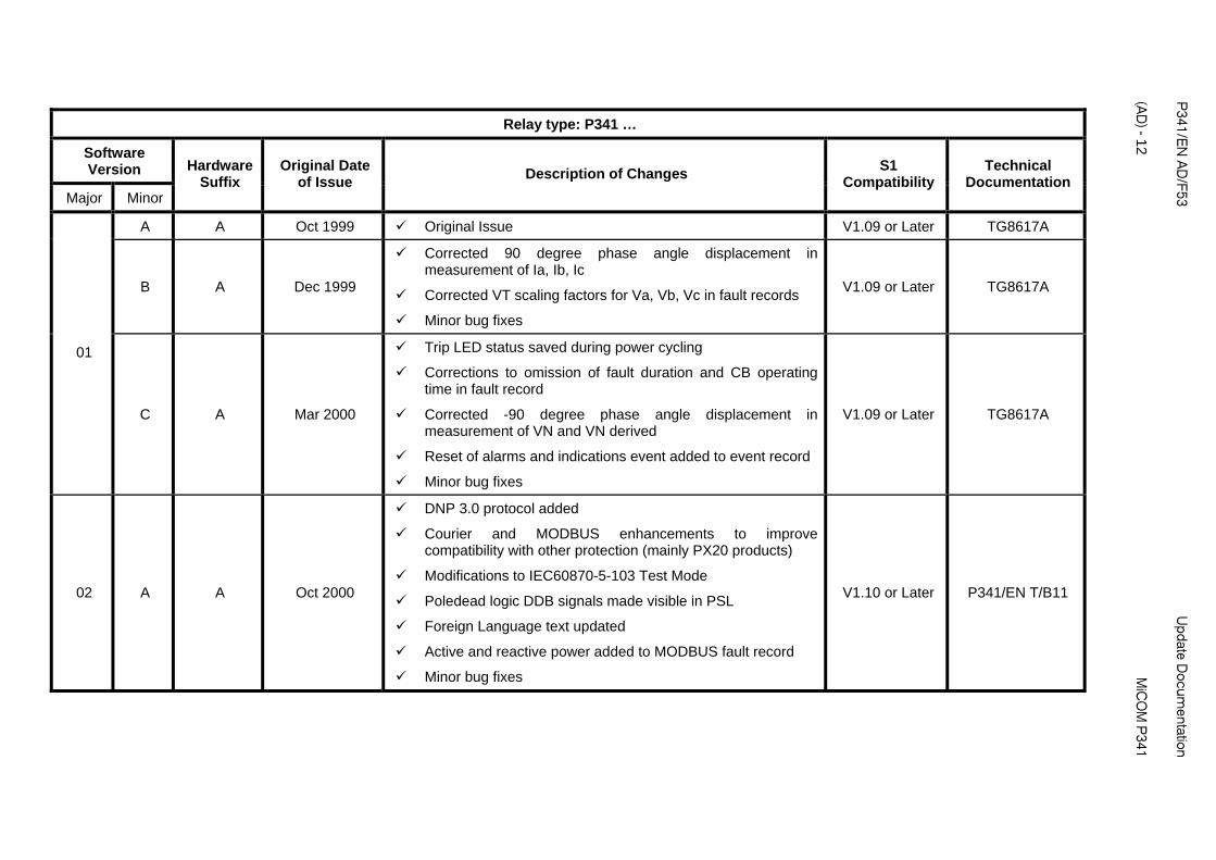
A A Oct 1999 Original Issue V1.09 or Later TG8617A
B A Dec 1999
Corrected 90 degree phase angle displacement in measurement of Ia, Ib, Ic
Corrected VT scaling factors for Va, Vb, Vc in fault records
Minor bug fixes
V1.09 or Later TG8617A
01
C A Mar 2000
Trip LED status saved during power cycling
Corrections to omission of fault duration and CB operating time in fault record
Corrected -90 degree phase angle displacement in measurement of VN and VN derived
Reset of alarms and indications event added to event record
Minor bug fixes
V1.09 or Later TG8617A
02 A A Oct 2000
DNP 3.0 protocol added
Courier and MODBUS enhancements to improve compatibility with other protection (mainly PX20 products)
Modifications to IEC60870-5-103 Test Mode
Poledead logic DDB signals made visible in PSL
Foreign Language text updated
Active and reactive power added to MODBUS fault record
Minor bug fixes
V1.10 or Later P341/EN T/B11
Update D
ocumentation
P
341/EN
AD
/F53
MiC
OM
P341
(A
D) - 13
Relay type: P341 …
Software Version
Major Minor
Hardware Suffix
Original Date of Issue
ription of Changes S1
Compatibility Technical
Documentation Desc
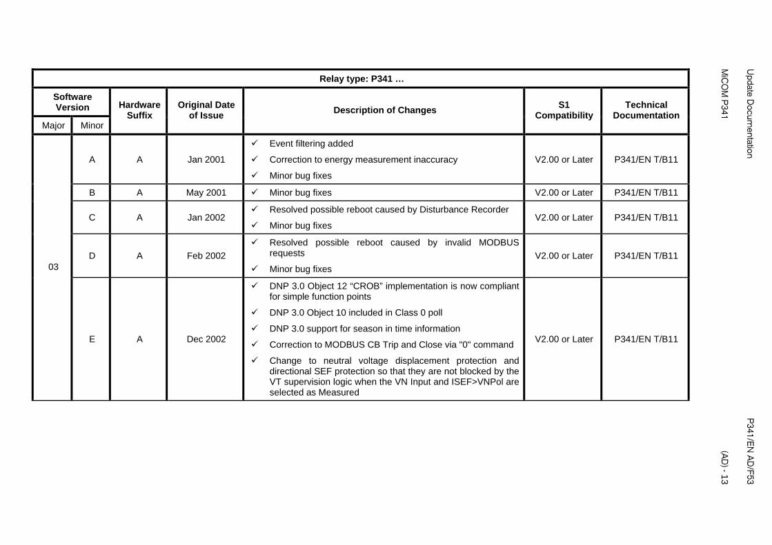
A A Jan 2001
Event filtering added
Correction to energy measurement inaccuracy
Minor bug fixes
V2.00 or Later P341/EN T/B11
B A May 2001 Minor bug fixes V2.00 or Later P341/EN T/B11
C A Jan 2002 Resolved possible reboot caused by Disturbance Recorder
Minor bug fixes V2.00 or Later P341/EN T/B11
D A Feb 2002
Resolved possible reboot caused by invalid MODBUS requests
Minor bug fixes
V2.00 or Later P341/EN T/B11 03
E A Dec 2002
DNP 3.0 Object 12 “CROB” implementation is now compliant for simple function points
DNP 3.0 Object 10 included in Class 0 poll
DNP 3.0 support for season in time information
Correction to MODBUS CB Trip and Close via "0" command
Change to neutral voltage displacement protection and directional SEF protection so that they are not blocked by the VT supervision logic when the VN Input and ISEF>VNPol are selected as Measured
V2.00 or Later P341/EN T/B11
P341/E
N A
D/F53
U
pdate Docum
entation
(AD
) - 14
MiC
OM
P341
Relay type: P341 …
Software Version
Major Minor
Hardware Suffix
Original Date of Issue
S1 Compatibility
Technical Documentation
Description of Changes
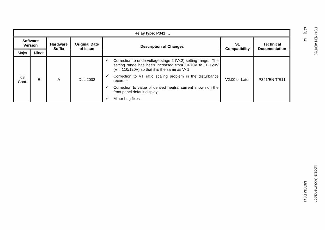
03 Cont.
E A Dec 2002
Correction to undervoltage stage 2 (V<2) setting range. The setting range has been increased from 10-70V to 10-120V (Vn=110/120V) so that it is the same as V<1
Correction to VT ratio scaling problem in the disturbance recorder
Correction to value of derived neutral current shown on the front panel default display.
Minor bug fixes
V2.00 or Later P341/EN T/B11
Update D
ocumentation
P
341/EN
AD
/F53
MiC
OM
P341
(A
D) - 15
Relay type: P341 …
Software Version
Major Minor
Hardware Suffix
Original Date of Issue
S1 Compatibility
Technical Documentation
Description of Changes
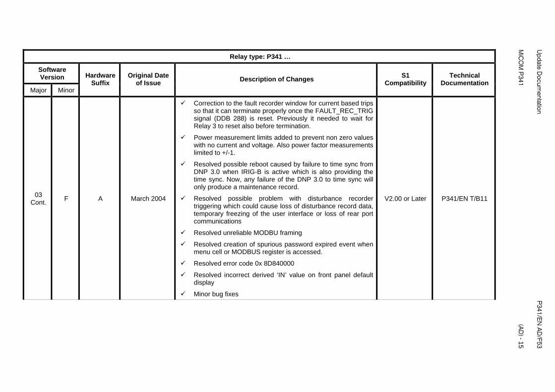
03 Cont.
F A March 2004
Correction to the fault recorder window for current based trips so that it can terminate properly once the FAULT_REC_TRIG signal (DDB 288) is reset. Previously it needed to wait for Relay 3 to reset also before termination.
Power measurement limits added to prevent non zero values with no current and voltage. Also power factor measurements limited to +/-1.
Resolved possible reboot caused by failure to time sync from DNP 3.0 when IRIG-B is active which is also providing the time sync. Now, any failure of the DNP 3.0 to time sync will only produce a maintenance record.
Resolved possible problem with disturbance recorder triggering which could cause loss of disturbance record data, temporary freezing of the user interface or loss of rear port communications
Resolved unreliable MODBU framing
Resolved creation of spurious password expired event when menu cell or MODBUS register is accessed.
Resolved error code 0x 8D840000
Resolved incorrect derived ‘IN’ value on front panel default display
Minor bug fixes
V2.00 or Later P341/EN T/B11
P341/E
N A
D/F53
U
pdate Docum
entation
(AD
) - 16
MiC
OM
P341
Relay type: P341 …
Software Version
Major Minor
Hardware Suffix
Original Date of Issue
S1 Compatibility
Technical Documentation
Description of Changes
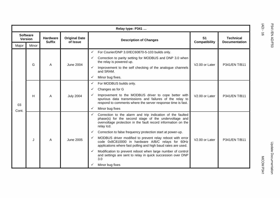
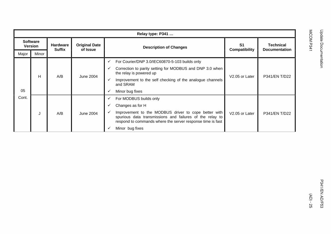
G A June 2004
For Courier/DNP 3.0/IEC60870-5-103 builds only.
Correction to parity setting for MODBUS and DNP 3.0 when the relay is powered up.
Improvement to the self checking of the analogue channels and SRAM.
Minor bug fixes.
V2.00 or Later P341/EN T/B11
H A July 2004
For MODBUS builds only.
Changes as for G
Improvement to the MODBUS driver to cope better with spurious data transmissions and failures of the relay to respond to comments where the server response time is fast.
Minor bug fixes
V2.00 or Later P341/EN T/B11
03
Cont.
J A June 2005
Correction to the alarm and trip indication of the faulted phase(s) for the second stage of the undervoltage and overvoltage protection in the fault record information on the relay Icd.
Correction to false frequency protection start at power-up.
MODBUS driver modified to prevent relay reboot with error code 0x8C810000 in hardware A/B/C relays for 60Hz applications where fast polling and high baud rates are used.
Modification to prevent reboot when large number of control and settings are sent to relay in quick succession over DNP 3.0
Minor bug fixes
V2.00 or Later P341/EN T/B11

Update D
ocumentation
P
341/EN
AD
/F53
MiC
OM
P341
(A
D) - 17
Relay type: P341 …
Software Version
Major Minor
Hardware Suffix
Original Date of Issue
Changes S1
Compatibility Technical
Documentation Description of
A A June 2001
Not released to production
Sensitive reverse power added
Neutral voltage displacement threshold, VN>1/2, increased from 50 to 80V (Vn=100/120V), 200 to 320 V (Vn=380/480V)
Earth fault polarizing voltage threshold, Vnpol, increased from 22 to 88V (Vn=100/120V) and 88 to 352V (Vn=380/480V)
cos phi and sin phi features added to SEF protection
Minor bug fixes
V2.01 or Later P341/EN T/B11
B A July 2001
Not released to production
Minor bug fix to background self check diagnostics introduced in 04A
V2.01 or Later P341/EN T/B11
C A Dec 2001 Minor bug fixes V2.01 or Later P341/EN T/B11
D A Jan 2002 Resolved possible reboot caused by Disturbance Recorder
Minor bug fixes V2.01 or Later P341/EN T/B11
E A Feb 2002
Resolved possible reboot caused by invalid MODBUS requests
Minor bug fixes
V2.01 or Later P341/EN T/B11
04
F A Dec 2002
Enhanced DNP 3.0 Object 10 support for Pulse On/Close control points
DNP 3.0 Object 10 included in Class 0 poll
DNP 3.0 support for season in time information
V2.01 or Later P341/EN T/B11
P341/E
N A
D/F53
U
pdate Docum
entation
(AD
) - 18
MiC
OM
P341
Relay type: P341 …
Software Version
Major Minor
Hardware Suffix
Original Date of Issue
S1 Compatibility
Technical Documentation
Description of Changes
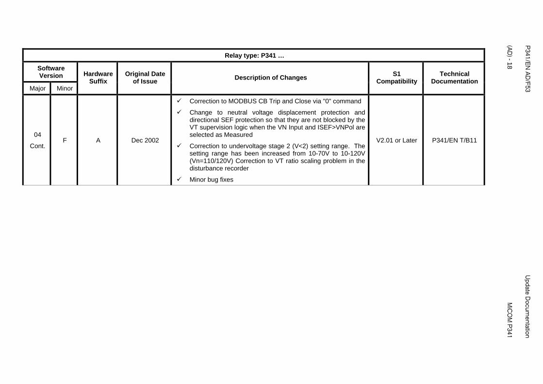
04
Cont. F A Dec 2002
Correction to MODBUS CB Trip and Close via "0" command
Change to neutral voltage displacement protection and directional SEF protection so that they are not blocked by the VT supervision logic when the VN Input and ISEF>VNPol are selected as Measured
Correction to undervoltage stage 2 (V<2) setting range. The setting range has been increased from 10-70V to 10-120V (Vn=110/120V) Correction to VT ratio scaling problem in the disturbance recorder
Minor bug fixes
V2.01 or Later P341/EN T/B11
Update D
ocumentation
P
341/EN
AD
/F53
MiC
OM
P341
(A
D) - 19
Relay type: P341 …
Software Version
Major Minor
Hardware Suffix
Original Date of Issue
S1 Compatibility
Technical Documentation
Description of Changes
G A March 2004
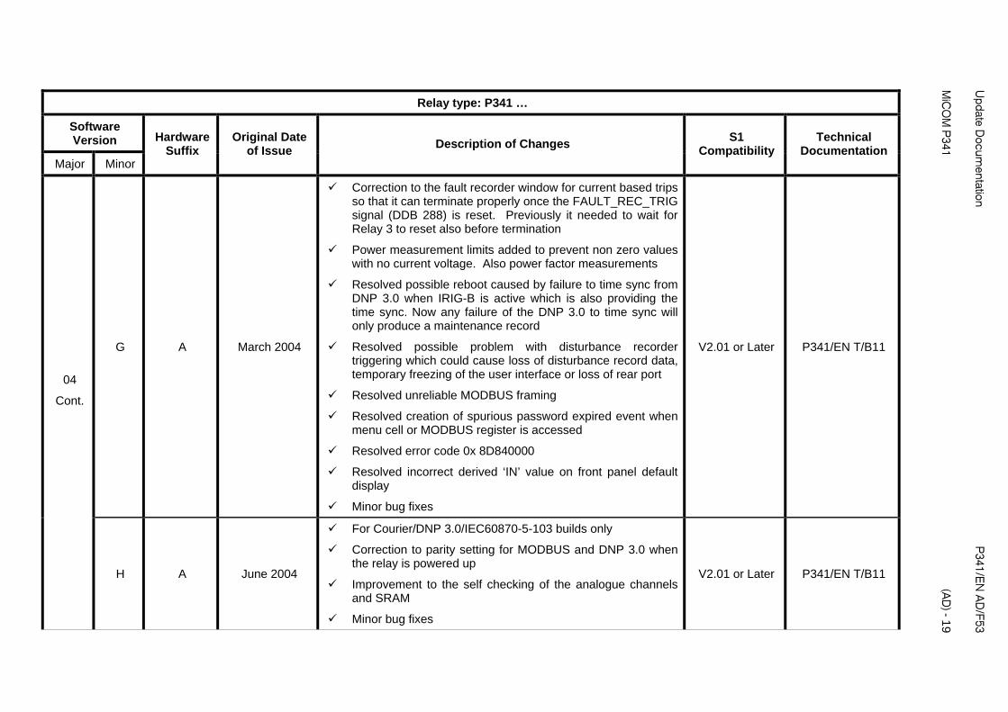
Correction to the fault recorder window for current based trips so that it can terminate properly once the FAULT_REC_TRIG signal (DDB 288) is reset. Previously it needed to wait for Relay 3 to reset also before termination
Power measurement limits added to prevent non zero values with no current voltage. Also power factor measurements
Resolved possible reboot caused by failure to time sync from DNP 3.0 when IRIG-B is active which is also providing the time sync. Now any failure of the DNP 3.0 to time sync will only produce a maintenance record
Resolved possible problem with disturbance recorder triggering which could cause loss of disturbance record data, temporary freezing of the user interface or loss of rear port
Resolved unreliable MODBUS framing
Resolved creation of spurious password expired event when menu cell or MODBUS register is accessed
Resolved error code 0x 8D840000
Resolved incorrect derived ‘IN’ value on front panel default display
Minor bug fixes
V2.01 or Later P341/EN T/B11
04
Cont.
H A June 2004
For Courier/DNP 3.0/IEC60870-5-103 builds only
Correction to parity setting for MODBUS and DNP 3.0 when the relay is powered up
Improvement to the self checking of the analogue channels and SRAM
Minor bug fixes
V2.01 or Later P341/EN T/B11

P341/E
N A
D/F53
U
pdate Docum
entation
(AD
) - 20
MiC
OM
P341
Relay type: P341 …
Software Version
Major Minor
Hardware Suffix
Original Date of Issue
Changes S1
Compatibility Technical
Documentation Description of
J A July 2004
For MODBUS builds only
Changes as for H
Improvement to the MODBUS driver to cope better with spurious data transmissions and failures of the relay to respond to commands where the server response time is fast
Minor bug fixes
V2.01 or Later P341/EN T/B11 04
Cont.
K A June 2004 Changes are the same as 03J V2.01 or Later P341/EN T/B11
05 A A/B Sept 2001
Not released to production
Thermal overload protection added
Control inputs added
PSL DDB list of signals increased from 512 to 1023 signals
PSL Data menu added with PSL Reference information for version history
Optional additional opto inputs and output contacts
New ‘Universal’ wide ranging opto inputs (Model number hardware suffix changed to B)
New output contacts with better break and continuous carry ratings (Model number hardware suffix changed to B)
Minor bug fixes
Courier and MODBUS builds only
V2.05 or Later P341/EN T/D22
Update D
ocumentation
P
341/EN
AD
/F53
MiC
OM
P341
(A
D) - 21
Relay type: P341 …
Software Version
Major Minor
Hardware Suffix
Original Date of Issue
Changes S1
Compatibility Technical
Documentation Description of
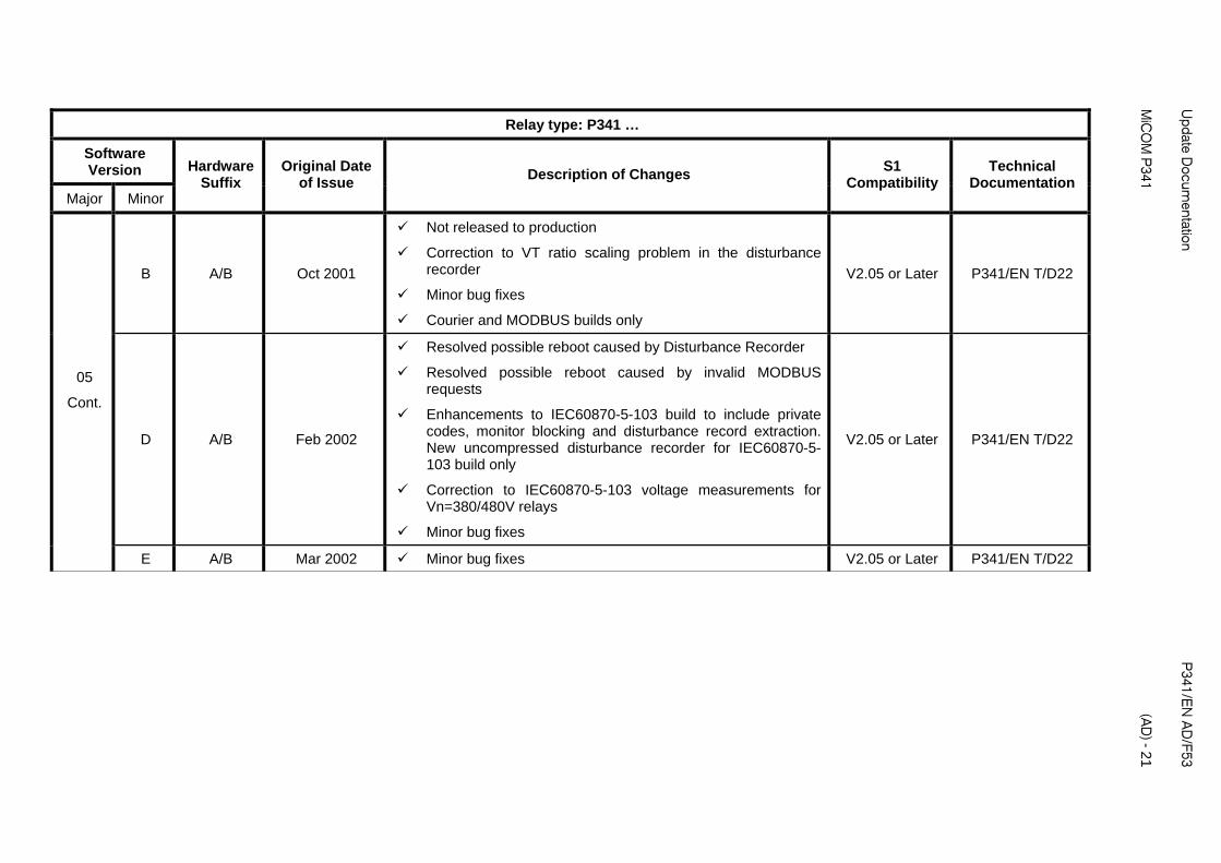
B A/B Oct 2001
Not released to production
Correction to VT ratio scaling problem in the disturbance recorder
Minor bug fixes
Courier and MODBUS builds only
V2.05 or Later P341/EN T/D22
D A/B Feb 2002
Resolved possible reboot caused by Disturbance Recorder
Resolved possible reboot caused by invalid MODBUS requests
Enhancements to IEC60870-5-103 build to include private codes, monitor blocking and disturbance record extraction. New uncompressed disturbance recorder for IEC60870-5-103 build only
Correction to IEC60870-5-103 voltage measurements for Vn=380/480V relays
Minor bug fixes
V2.05 or Later P341/EN T/D22
05
Cont.
E A/B Mar 2002 Minor bug fixes V2.05 or Later P341/EN T/D22
P341/E
N A
D/F53
U
pdate Docum
entation
(AD
) - 22
MiC
OM
P341
Relay type: P341 …
Software Version
Major Minor
Hardware Suffix
Original Date of Issue
S1 Compatibility
Technical Documentation
Description of Changes
05
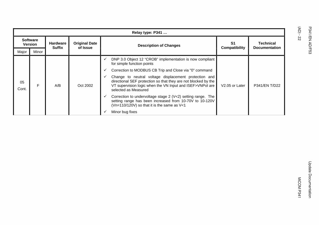
Cont. F A/B Oct 2002
DNP 3.0 Object 12 “CROB” implementation is now compliant for simple function points
Correction to MODBUS CB Trip and Close via "0" command
Change to neutral voltage displacement protection and directional SEF protection so that they are not blocked by the VT supervision logic when the VN Input and ISEF>VNPol are selected as Measured
Correction to undervoltage stage 2 (V<2) setting range. The setting range has been increased from 10-70V to 10-120V (Vn=110/120V) so that it is the same as V<1
Minor bug fixes
V2.05 or Later P341/EN T/D22
Update D
ocumentation
P
341/EN
AD
/F53
MiC
OM
P341
(A
D) - 23
Relay type: P341 …
Software Version
Major Minor
Hardware Suffix
Original Date of Issue
S1 Compatibility
Technical Documentation
Description of Changes
05
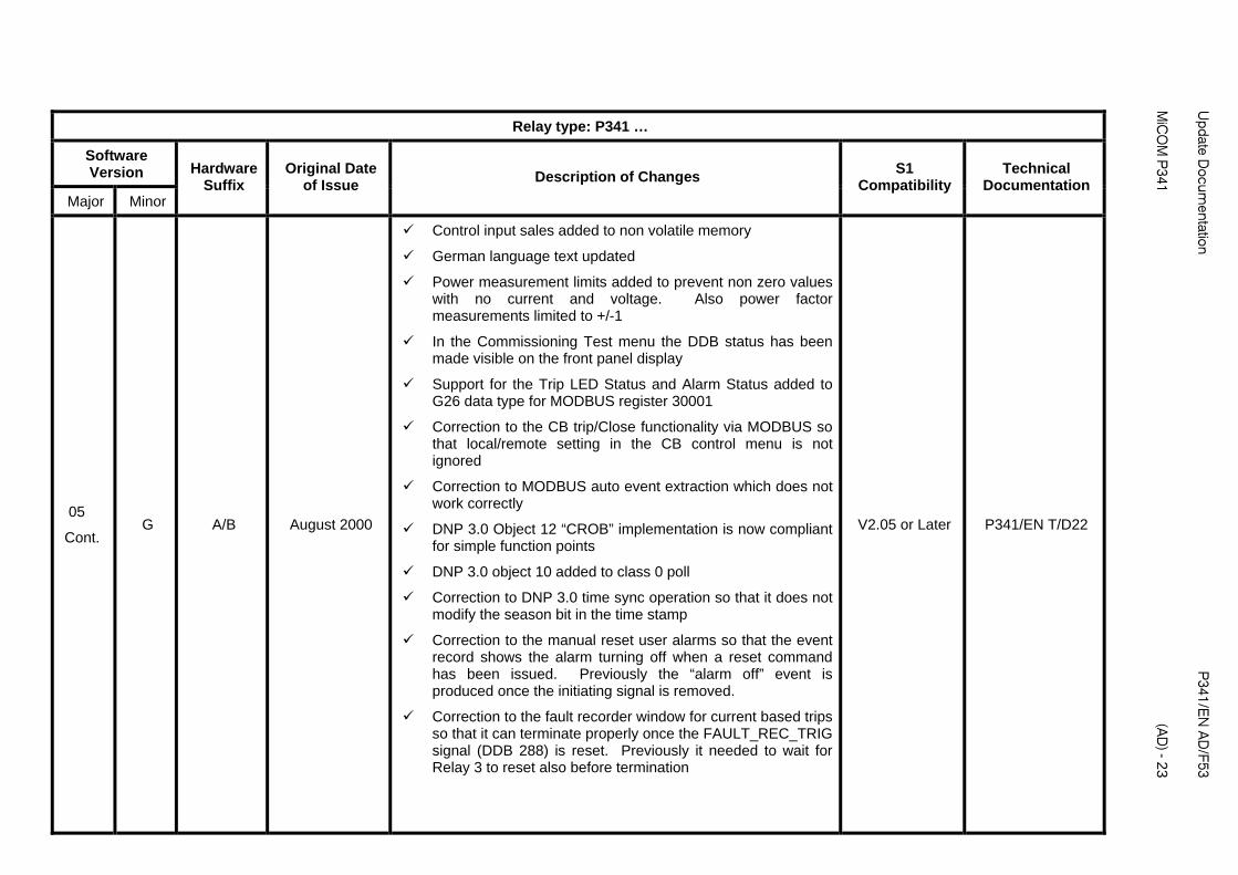
Cont. G A/B August 2000
Control input sales added to non volatile memory
German language text updated
Power measurement limits added to prevent non zero values with no current and voltage. Also power factor measurements limited to +/-1
In the Commissioning Test menu the DDB status has been made visible on the front panel display
Support for the Trip LED Status and Alarm Status added to G26 data type for MODBUS register 30001
Correction to the CB trip/Close functionality via MODBUS so that local/remote setting in the CB control menu is not ignored
Correction to MODBUS auto event extraction which does not work correctly
DNP 3.0 Object 12 “CROB” implementation is now compliant for simple function points
DNP 3.0 object 10 added to class 0 poll
Correction to DNP 3.0 time sync operation so that it does not modify the season bit in the time stamp
Correction to the manual reset user alarms so that the event record shows the alarm turning off when a reset command has been issued. Previously the “alarm off” event is produced once the initiating signal is removed.
Correction to the fault recorder window for current based trips so that it can terminate properly once the FAULT_REC_TRIG signal (DDB 288) is reset. Previously it needed to wait for Relay 3 to reset also before termination
V2.05 or Later P341/EN T/D22

P341/E
N A
D/F53
U
pdate Docum
entation
(AD
) - 24
MiC
OM
P341
Relay type: P341 …
Software Version
Major Minor
Hardware Suffix
Original Date of Issue
S1 Compatibility
Technical Documentation
Description of Changes
05.
Cont. G A/B August 2000
Resolved possible reboot caused by failure to time sync from DNP 3.0 when IRIG-B is active which is also providing the time sync. Now, any failure of the DNP 3.0 to time sync will only produce a maintenance record.
Correction to the alarm and trip indication of the faulted phase(s) for the second stage of the undervoltage and overvoltage protection in the fault record information on the relay Icd
Correction to the C32CS error when extracting and saving an uncompressed disturbance record from the P341 through the front port using MiCOM S1 Studio. This only applies to P341 IEC60870-5-103 protocol builds since this is the only communication option which supports uncompressed disturbance records. The error is caused by unavailable opto inputs or relay contacts being assigned to digital inputs in the Disturbance Recorder menu.
Resolved possible problem with disturbance recorder triggering which could cause loss of disturbance record data, temporary freezing of the user interface or loss of rear port communications
Resolved unreliable MODBUS framing
Resolved creation of spurious password expired event when menu cell or MODBUS register is accessed.
Resolved error code 0x 8D840000
Resolved incorrect derived ‘IN’ value on front panel default display
Minor bug fixes
V2.05 or Later P341/EN T/D22
Update D
ocumentation
P
341/EN
AD
/F53
MiC
OM
P341
(A
D) - 25
Relay type: P341 …
Software Version
Major Minor
Hardware Suffix
Original Date of Issue
S1 Compatibility
Technical Documentation
Description of Changes
H A/B June 2004
For Courier/DNP 3.0/IEC60870-5-103 builds only
Correction to parity setting for MODBUS and DNP 3.0 when the relay is powered up
Improvement to the self checking of the analogue channels and SRAM
Minor bug fixes
V2.05 or Later P341/EN T/D22
05
Cont.
J A/B June 2004
For MODBUS builds only
Changes as for H
Improvement to the MODBUS driver to cope better with spurious data transmissions and failures of the relay to respond to commands where the server response time is fast
Minor bug fixes
V2.05 or Later P341/EN T/D22

P341/E
N A
D/F53
U
pdate Docum
entation
(AD
) - 26
MiC
OM
P341
Relay type: P341 …
Software Version
Major Minor
Hardware Suffix
Original Date of Issue
S1 Compatibility
Technical Documentation
Description of Changes
05
Cont. K A/B June 2004
MODBUS Time Transmission Format selectable via MODBUS only setting as Standard or Reverse for transmission of byte order
DO/PU ratio changed from 95% to 98% for Over/Under Voltage protection. Trip threshold changed from 1.05, 0.95 Vs to 1 Vs for Over and Under Voltage and NVD protection. TMS setting of Under/Over Voltage protection reduced from 0.5 to 0.05.
Correction to false frequency protection start at power-up. MODBUS driver modified to prevent relay reboot with error code 0x8C810000 in hardware A/B/C relays for 60Hz applications where fast polling and high baud rates are used.
Modification to prevent reboot when large number of control and settings are sent to relay in quick succession over DNP 3.0
IEC60870-5-103. Status of summer bit now works correctly in time sync command.
Correction to DNP 3.0 software where settings download from MiCOM S1 Studio can fail for relays that have model dependent I/O configurations.
Minor bug fixes
V2.05 or Later P341/EN T/D22
05 cont
L A/B July 2007
Correction to P341 Directional SEF which did not operate until the SEF 'Mode' setting is changed.
Courier cell addresses for the IDMT characteristic enhancements in 06 software have been applied to 05K maintenance release, making S1 setting files incompatible. This has been corrected in 05L.
Minor bug fixes
V2.05 or later P341/EN T/D22

Update D
ocumentation
P
341/EN
AD
/F53
MiC
OM
P341
(A
D) - 27
Relay type: P341 …
Software Version
Major Minor
Hardware Suffix
Original Date of Issue
Changes S1
Compatibility Technical
Documentation Description of
06 A A/C Aug 2000
Not released to production
Additional IDMT characteristics for overcurrent protection (rectifier and RI curve), earth fault protection (RI and IDG curve) and sensitive earth fault protection (IDG curve)
Change to time dial setting range of IEEE and US curves. Previously curves were based on TD/7 where TD = 0.5-15. Now, curves are based on TD where TD = 0.01-100. Also, includes change to US ST Inverse (C02) curve. K constant and L constant multiplied x 7 because of change to TD, now K=0.16758 and L=0.11858
Angle measurements for sequence quantities in Measurements 1 menu added
Optional 2nd rear communication port added
New power supply with increased output rating and reduced dc inrush current (typically < 10A). (Model number hardware changed to suffix C)
Wider setting range for Power and Sensitive Power protection. P>1/2 (reverse power) and P<1/2 (low forward power) maximum setting changed from 40In to 300In W (Vn=100/120V) and from 160In W to 1200In W (Vn=380/480V). Sen –P>1/2 and Sen P<1/2 maximum setting changed from 15In to 100In W (Vn=100/120V) and from 60In to 400In W (Vn=380/480V). There is also an additional setting for the Power and Sensitive Power protection to select the Operating mode as Generating or Motoring
V2.06 or Later P341/EN M/E33
P341/E
N A
D/F53
U
pdate Docum
entation
(AD
) - 28
MiC
OM
P341
Relay type: P341 …
Software Version
Major Minor
Hardware Suffix
Original Date of Issue
S1 Compatibility
Technical Documentation
Description of Changes
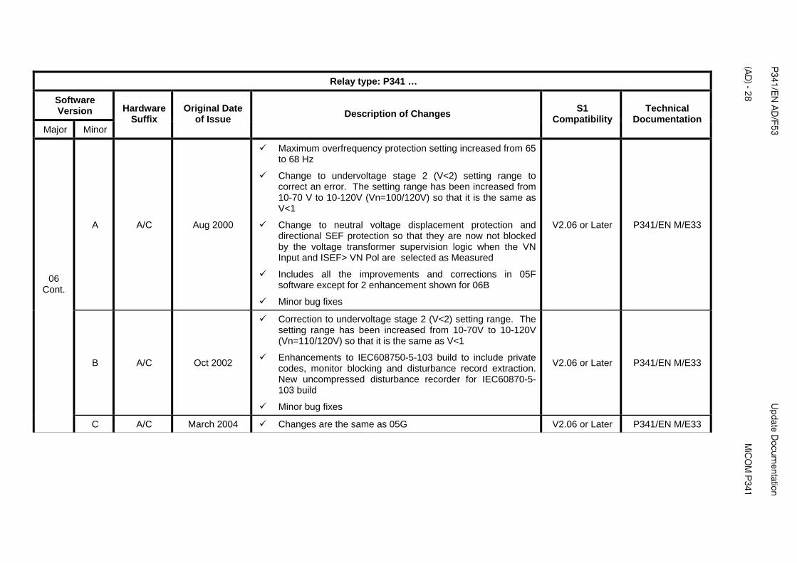
A A/C Aug 2000
Maximum overfrequency protection setting increased from 65 to 68 Hz
Change to undervoltage stage 2 (V<2) setting range to correct an error. The setting range has been increased from 10-70 V to 10-120V (Vn=100/120V) so that it is the same as V<1
Change to neutral voltage displacement protection and directional SEF protection so that they are now not blocked by the voltage transformer supervision logic when the VN Input and ISEF> VN Pol are selected as Measured
Includes all the improvements and corrections in 05F software except for 2 enhancement shown for 06B
Minor bug fixes
V2.06 or Later P341/EN M/E33
B A/C Oct 2002
Correction to undervoltage stage 2 (V<2) setting range. The setting range has been increased from 10-70V to 10-120V (Vn=110/120V) so that it is the same as V<1
Enhancements to IEC608750-5-103 build to include private codes, monitor blocking and disturbance record extraction. New uncompressed disturbance recorder for IEC60870-5-103 build
Minor bug fixes
V2.06 or Later P341/EN M/E33
06 Cont.
C A/C March 2004 Changes are the same as 05G V2.06 or Later P341/EN M/E33

Update D
ocumentation
P
341/EN
AD
/F53
MiC
OM
P341
(A
D) - 29
Relay type: P341 …
Software Version
Major Minor
Hardware Suffix
Original Date of Issue
S1 Compatibility
Technical Documentation
Description of Changes
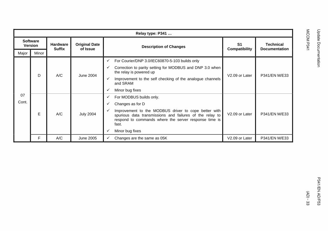
D A/C June 2004
For Courier/DNP 3.0/IEC60870-5-103 builds only.
Correction to parity setting for MODBUS and DNP 3.0 when the relay is powered up.
Improvement to the self checking of the analogue channels and SRAM.
Minor bug fixes
V2.06 or Later P341/EN M/E33
E A/C July 2004
For MODBUS builds only.
Changes as for D
Improvement to the MODBUS driver to cope better with spurious data transmissions and failures of the relay to respond to commands where the serve response time is fast.
Minor big fixes
V2.06 or Later P341/EN M/E33
06
Cont.
F A/C June 2005 Changes are the same as 05K V2.06 or Later P341/EN M/E33

P341/E
N A
D/F53
U
pdate Docum
entation
(AD
) - 30
MiC
OM
P341
Relay type: P341 …
Software Version
Major Minor
Hardware Suffix
Original Date of Issue
Changes S1
Compatibility Technical
Documentation Description of
A A/C Apr 2003
Not released to production
Optional additional 4 analogue inputs and 4 outputs (current loop inputs and outputs – CLIO)
Number of alarms increased from 64 to 96 (New Alarm Status 3 word - 32 bit)
Additional user alarms. Previously 1 manual reset and 2 self reset user alarms, now 12 manual reset and 4 self reset user alarms
Control Input states added to non volatile memory
German language text updated
Courier and MODBUS builds only
Minor bug fixes
V2.09 or Later P341/EN M/E33
07
B A/C Oct 2003
Power measurement limits added to prevent none zero values with no current and voltage. Also power factor measurements limited to +/-1
In the Commissioning Test menu the DDB status has been made visible on the front panel display
Support for Trip LED Status and Alarm Status added to G26 data type for MODBUS register 30001
V2.09 or Later P341/EN M/E33
Update D
ocumentation
P
341/EN
AD
/F53
MiC
OM
P341
(A
D) - 31
Relay type: P341 …
Software Version
Major Minor
Hardware Suffix
Original Date of Issue
S1 Compatibility
Technical Documentation
Description of Changes
07 Cont.
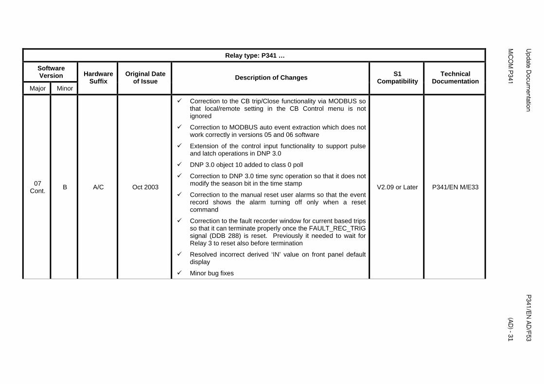
B A/C Oct 2003
Correction to the CB trip/Close functionality via MODBUS so that local/remote setting in the CB Control menu is not ignored
Correction to MODBUS auto event extraction which does not work correctly in versions 05 and 06 software
Extension of the control input functionality to support pulse and latch operations in DNP 3.0
DNP 3.0 object 10 added to class 0 poll
Correction to DNP 3.0 time sync operation so that it does not modify the season bit in the time stamp
Correction to the manual reset user alarms so that the event record shows the alarm turning off only when a reset command
Correction to the fault recorder window for current based trips so that it can terminate properly once the FAULT_REC_TRIG signal (DDB 288) is reset. Previously it needed to wait for Relay 3 to reset also before termination
Resolved incorrect derived ‘IN’ value on front panel default display
Minor bug fixes
V2.09 or Later P341/EN M/E33
P341/E
N A
D/F53
U
pdate Docum
entation
(AD
) - 32
MiC
OM
P341
Relay type: P341 …
Software Version
Major Minor
Hardware Suffix
Original Date of Issue
S1 Compatibility
Technical Documentation
Description of Changes
07
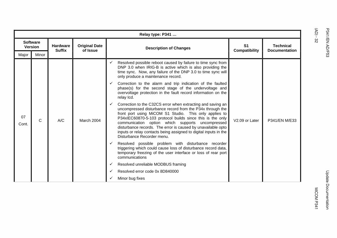
Cont. C A/C March 2004
Resolved possible reboot caused by failure to time sync from DNP 3.0 when IRIG-B is active which is also providing the time sync. Now, any failure of the DNP 3.0 to time sync will only produce a maintenance record.
Correction to the alarm and trip indication of the faulted phase(s) for the second stage of the undervoltage and overvoltage protection in the fault record information on the relay Icd.
Correction to the C32CS error when extracting and saving an uncompressed disturbance record from the P34x through the front port using MiCOM S1 Studio. This only applies to P34xIEC60870-5-103 protocol builds since this is the only communication option which supports uncompressed disturbance records. The error is caused by unavailable opto inputs or relay contacts being assigned to digital inputs in the Disturbance Recorder menu.
Resolved possible problem with disturbance recorder triggering which could cause loss of disturbance record data, temporary freezing of the user interface or loss of rear port communications
Resolved unreliable MODBUS framing
Resolved error code 0x 8D840000
Minor bug fixes
V2.09 or Later P341/EN M/E33
Update D
ocumentation
P
341/EN
AD
/F53
MiC
OM
P341
(A
D) - 33
Relay type: P341 …
Software Version
Major Minor
Hardware Suffix
Original Date of Issue
S1 Compatibility
Technical Documentation
Description of Changes
D A/C June 2004
For Courier/DNP 3.0/IEC60870-5-103 builds only
Correction to parity setting for MODBUS and DNP 3.0 when the relay is powered up
Improvement to the self checking of the analogue channels and SRAM
Minor bug fixes
V2.09 or Later P341/EN M/E33
E A/C July 2004
For MODBUS builds only.
Changes as for D
Improvement to the MODBUS driver to cope better with spurious data transmissions and failures of the relay to respond to commands where the server response time is fast.
Minor bug fixes
V2.09 or Later P341/EN M/E33
07
Cont.
F A/C June 2005 Changes are the same as 05K V2.09 or Later P341/EN M/E33
P341/E
N A
D/F53
U
pdate Docum
entation
(AD
) - 34
MiC
OM
P341
Relay type: P341 …
Software Version
Major Minor
Hardware Suffix
Original Date of Issue
Changes S1
Compatibility Technical
Documentation Description of
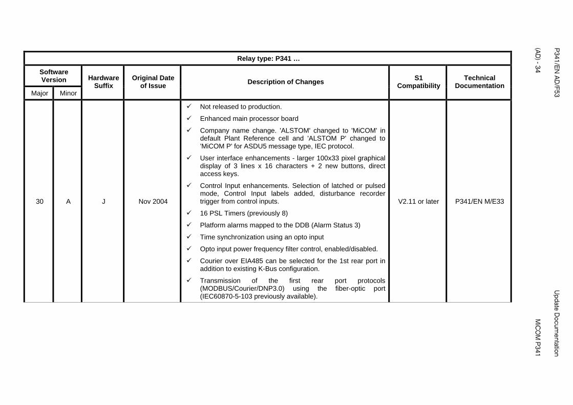
30 A J Nov 2004
Not released to production.
Enhanced main processor board
Company name change. 'ALSTOM' changed to 'MiCOM' in default Plant Reference cell and 'ALSTOM P' changed to 'MiCOM P' for ASDU5 message type, IEC protocol.
User interface enhancements - larger 100x33 pixel graphical display of 3 lines x 16 characters + 2 new buttons, direct access keys.
Control Input enhancements. Selection of latched or pulsed mode, Control Input labels added, disturbance recorder trigger from control inputs.
16 PSL Timers (previously 8)
Platform alarms mapped to the DDB (Alarm Status 3)
Time synchronization using an opto input
Opto input power frequency filter control, enabled/disabled.
Courier over EIA485 can be selected for the 1st rear port in addition to existing K-Bus configuration.
Transmission of the first rear port protocols (MODBUS/Courier/DNP3.0) using the fiber-optic port (IEC60870-5-103 previously available).
V2.11 or later P341/EN M/E33
Update D
ocumentation
P
341/EN
AD
/F53
MiC
OM
P341
(A
D) - 35
Relay type: P341 …
Software Version
Major Minor
Hardware Suffix
Original Date of Issue
S1 Compatibility
Technical Documentation
Description of Changes
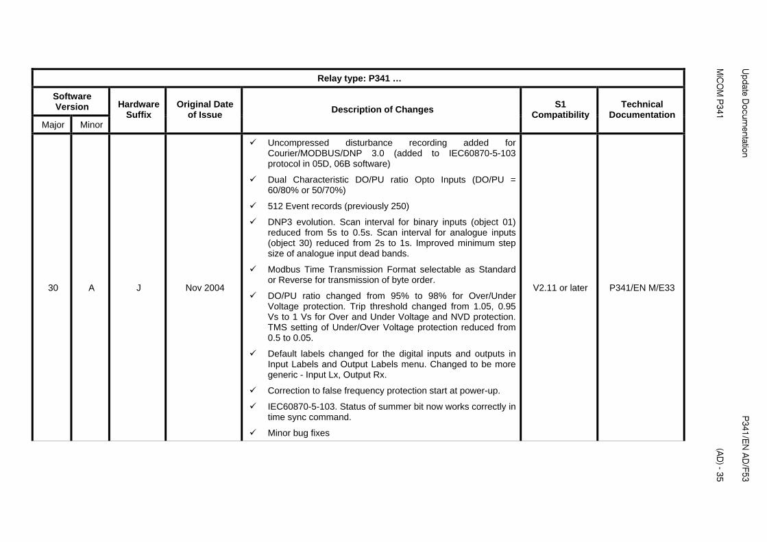
30 A J Nov 2004
Uncompressed disturbance recording added for Courier/MODBUS/DNP 3.0 (added to IEC60870-5-103 protocol in 05D, 06B software)
Dual Characteristic DO/PU ratio Opto Inputs (DO/PU = 60/80% or 50/70%)
512 Event records (previously 250)
DNP3 evolution. Scan interval for binary inputs (object 01) reduced from 5s to 0.5s. Scan interval for analogue inputs (object 30) reduced from 2s to 1s. Improved minimum step size of analogue input dead bands.
Modbus Time Transmission Format selectable as Standard or Reverse for transmission of byte order.
DO/PU ratio changed from 95% to 98% for Over/Under Voltage protection. Trip threshold changed from 1.05, 0.95 Vs to 1 Vs for Over and Under Voltage and NVD protection. TMS setting of Under/Over Voltage protection reduced from 0.5 to 0.05.
Default labels changed for the digital inputs and outputs in Input Labels and Output Labels menu. Changed to be more generic - Input Lx, Output Rx.
Correction to false frequency protection start at power-up.
IEC60870-5-103. Status of summer bit now works correctly in time sync command.
Minor bug fixes
V2.11 or later P341/EN M/E33
P341/E
N A
D/F53
U
pdate Docum
entation
(AD
) - 36
MiC
OM
P341
Relay type: P341 …
Software Version
Major Minor
Hardware Suffix
Original Date of Issue
S1 Compatibility
Technical Documentation
Description of Changes
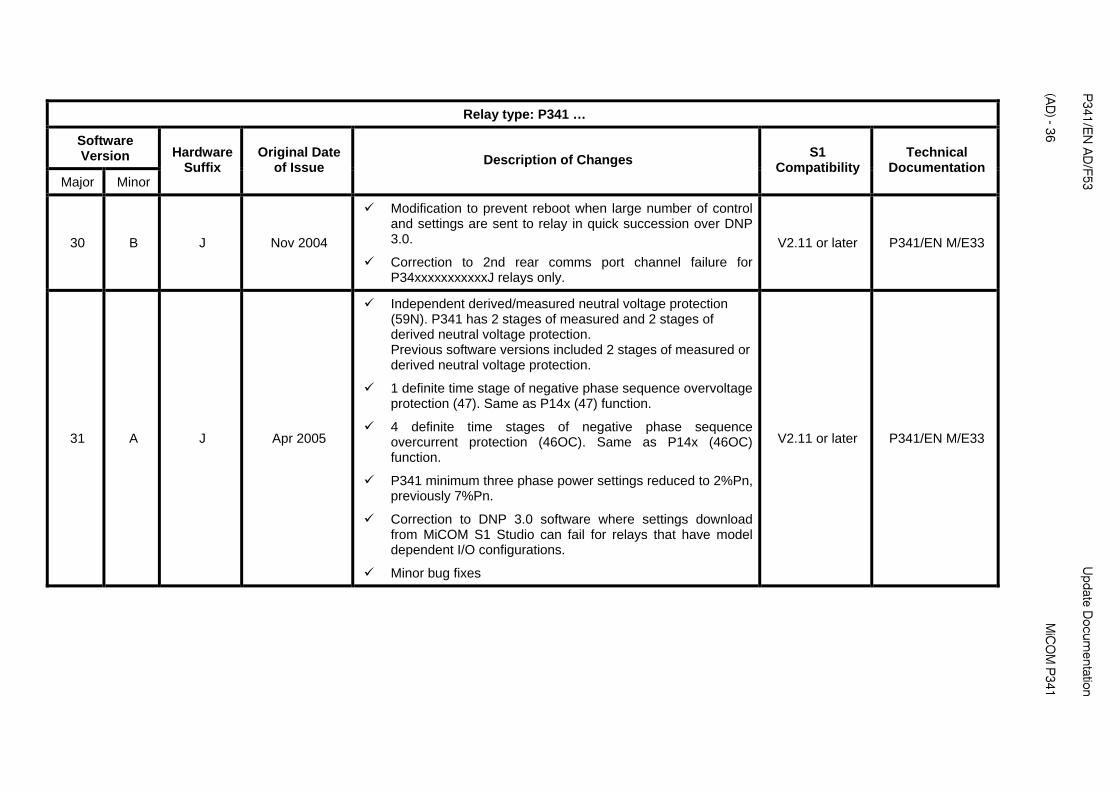
30 B J Nov 2004
Modification to prevent reboot when large number of control and settings are sent to relay in quick succession over DNP 3.0.
Correction to 2nd rear comms port channel failure for P34xxxxxxxxxxxJ relays only.
V2.11 or later P341/EN M/E33
31 A J Apr 2005
Independent derived/measured neutral voltage protection (59N). P341 has 2 stages of measured and 2 stages of derived neutral voltage protection. Previous software versions included 2 stages of measured or derived neutral voltage protection.
1 definite time stage of negative phase sequence overvoltage protection (47). Same as P14x (47) function.
4 definite time stages of negative phase sequence overcurrent protection (46OC). Same as P14x (46OC) function.
P341 minimum three phase power settings reduced to 2%Pn, previously 7%Pn.
Correction to DNP 3.0 software where settings download from MiCOM S1 Studio can fail for relays that have model dependent I/O configurations.
Minor bug fixes
V2.11 or later P341/EN M/E33

Update D
ocumentation
P
341/EN
AD
/F53
MiC
OM
P341
(A
D) - 37
Relay type: P341 …
Software Version
Major Minor
Hardware Suffix
Original Date of Issue
Changes S1
Compatibility Technical
Documentation Description of
32 A J March 2006
Not released to production.
Phase rotation function added. Can select phase rotation as ABC or ACB for all 3 phase current and voltage inputs. Can also individually select which 2 phases are swapped for any of the 3 phase current and voltage inputs. New menu column 'System Config' with phase rotation settings.
In P34x relays the maximum number of disturbance recorder analogue channels has been increased in most relay models so that all analogue inputs can be recorded. In the P341 the maximum number of recorded channels has remained as 8 but now channels can be set as unused if required.
Number of PSL DDB signals increased from 1023 to 1408 and DDBs re-organized. This means that the PSL created in version 32 software is not compatible to PSL created in previous software versions and vice versa.
Setting Group selection via 2 new DDB signals makes it possible to select a setting group via any opto input or remotely via a Control Input. Previously, the 4 setting groups could be selected using fixed opto inputs, 1 and 2.
An 'Any Trip' DDB has been created to allow any contact(s) to be used as the trip indication. Previously, the Any Trip signal was defined as operation of Relay contact 3. The Any Trip signal operates the Trip LED, initiates the breaker fail logic and maintenance counters and is used in the fault recorder logic.
Minor changes to description of CT and VT Ratio settings.
Number of maintenance records increased from 5 to 10.
V2.14 or later P341/EN M/E33, P341/EN AD/E43

P341/E
N A
D/F53
U
pdate Docum
entation
(AD
) - 38
MiC
OM
P341
Relay type: P341 …
Software Version
Major Minor
Hardware Suffix
Original Date of Issue
S1 Compatibility
Technical Documentation
Description of Changes
A J March 2006
Inter frame gap added between frames in multi-frame transmission of DNP 3.0 messages to be compatible with C264.
Correction to error in NPS directional overcurrent operating time delay. The excess in the operating time (always less than 1s) only occurs when set to directional.
Correction to intermittent incorrect IRIG-B status indication of 'Card Failed' with healthy IRIG-B source.
Minor bug fixes
V2.14 or later P341/EN M/E33, P341/EN AD/E43
B J May 2006 Minor bug fixes V2.14 or later P341/EN M/E33, P341/EN AD/E43
C J October 2006
MODBUS allows individual 16 bit register pairs that make up 32 bit data to be accessed individually.
Correction to fast operation of overcurrent protection with IEEE/US inverse time reset characteristic.
Minor bug fixes
V2.14 or later P341/EN M/E33, P341/EN AD/E43
32
Cont..
D J Dec 2006
Correction to P341 Directional Sensitive Earth Fault (Forward or reverse) function. Function does not operate if SEF/REF Protection is initially disabled in the configuration column and SEF Mode is set to 'SEF' (default setting) when the relay is booted up. Correct operation will only occur when the SEF Mode setting is changed (submitted) and changed back to 'SEF' or the relay is rebooted with SEF/REF enabled in the configuration column.
Minor bug fixes
V2.14 or later P341/EN M/E33, P341/EN AD/E43
Update D
ocumentation
P
341/EN
AD
/F53
MiC
OM
P341
(A
D) - 39
Relay type: P341 …
Software Version
Major Minor
Hardware Suffix
Original Date of Issue
S1 Compatibility
Technical Documentation
Description of Changes
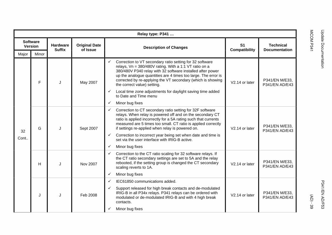
F J May 2007
Correction to VT secondary ratio setting for 32 software relays, Vn = 380/480V rating. With a 1:1 VT ratio on a 380/480V P340 relay with 32 software installed after power up the analogue quantities are 4 times too large. The error is corrected by re-applying the VT secondary (which is showing the correct value) setting.
Local time zone adjustments for daylight saving time added to Date and Time menu
Minor bug fixes
V2.14 or later P341/EN M/E33, P341/EN AD/E43
G J Sept 2007
Correction to CT secondary ratio setting for 32F software relays. When relay is powered off and on the secondary CT ratio is applied incorrectly for a 5A rating such that currents measured are 5 times too small. CT ratio is applied correctly if settings re-applied when relay is powered on.
Correction to incorrect year being set when date and time is set via the user interface with IRIG-B active.
Minor bug fixes
V2.14 or later P341/EN M/E33, P341/EN AD/E43
H J Nov 2007
Correction to the CT ratio scaling for 32 software relays. If the CT ratio secondary settings are set to 5A and the relay rebooted, if the setting group is changed the CT secondary scaling reverts to 1A.
Minor bug fixes
V2.14 or later P341/EN M/E33, P341/EN AD/E43
32
Cont..
J J Feb 2008
IEC61850 communications added.
Support released for high break contacts and de-modulated IRIG-B in all P34x relays. P341 relays can be ordered with modulated or de-modulated IRIG-B and with 4 high break contacts.
Minor bug fixes
V2.14 or later P341/EN M/E33, P341/EN AD/E43
P341/E
N A
D/F53
U
pdate Docum
entation
(AD
) - 40
MiC
OM
P341
Relay type: P341 …
Software Version
Major Minor
Hardware Suffix
Original Date of Issue
Description of Changes S1
Compatibility Technical
Documentation
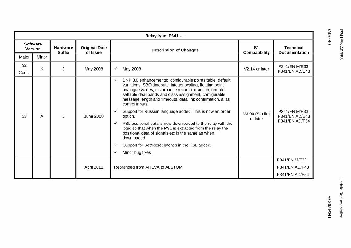
32
Cont.. K J May 2008 May 2008 V2.14 or later
P341/EN M/E33, P341/EN AD/E43
33 A J June 2008
DNP 3.0 enhancements: configurable points table, default variations, SBO timeouts, integer scaling, floating point analogue values, disturbance record extraction, remote settable deadbands and class assignment, configurable message length and timeouts, data link confirmation, alias control inputs.
Support for Russian language added. This is now an order option.
PSL positional data is now downloaded to the relay with the logic so that when the PSL is extracted from the relay the positional data of signals etc is the same as when downloaded.
Support for Set/Reset latches in the PSL added.
Minor bug fixes
V3.00 (Studio) or later
P341/EN M/E33, P341/EN AD/E43 P341/EN AD/F54
April 2011 Rebranded from AREVA to ALSTOM
P341/EN M/F33
P341/EN AD/F43
P341/EN AD/F54
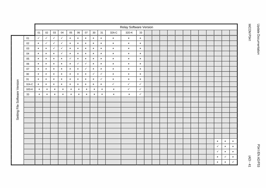
Relay Software Version
01 02 03 04 05 06 07 30 31 32A-C 32D-K 33
01
02
03
04
05
06
07
30
31
32A-C
32D-K
33
Set
ting
File
Sof
twar
e V
ersi
on
Update D
ocumentation
P
341/EN
AD
/F53
MiC
OM
P341
(A
D) - 41
P341/E
N A
D/F53
U
pdate Docum
entation
(AD
) - 42
MiC
OM
P341
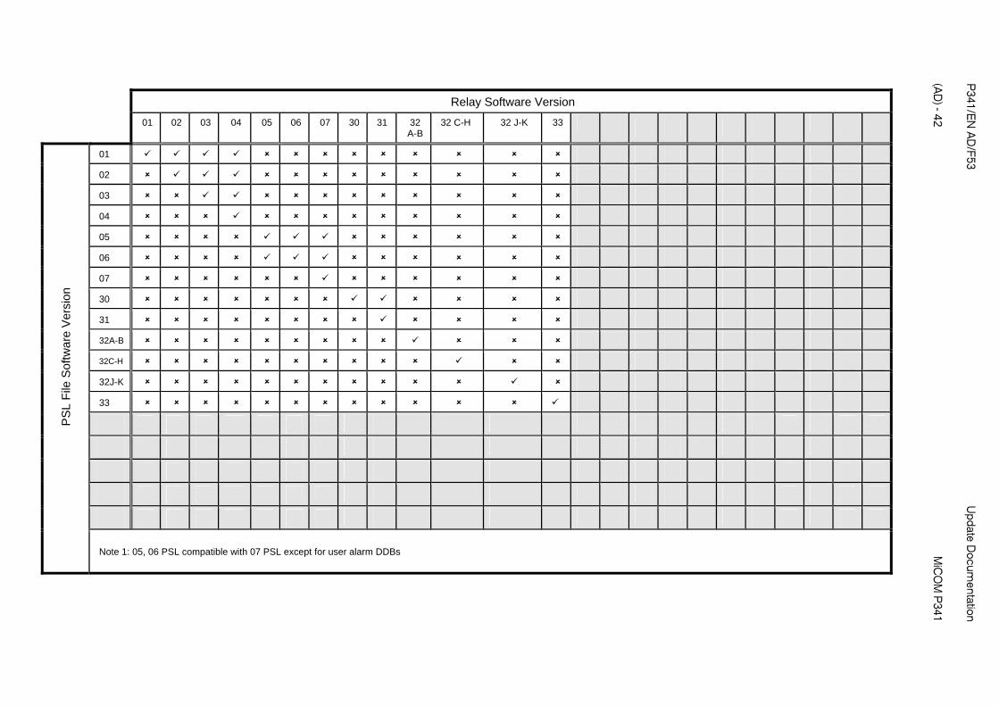
Relay Software Version
01 02 03 04 05 06 07 30 31 32 A-B
32 C-H 32 J-K 33
01
02
03
04
05
06
07
30
31
32A-B
32C-H
32J-K
33
PS
L F
ile S
oftw
are
Ver
sion
Note 1: 05, 06 PSL compatible with 07 PSL except for user alarm DDBs

Update D
ocumentation
P
341/EN
AD
/F53
MiC
OM
P341
(A
D) - 43
Relay Software Version
01 02 03 04 05
A-E 05 F-J
05K 06
A-E 06F
07 A-E
07F 30 31 32
A-B 32
C-D 32
E-K 33
01
02
03
04
05A-E
05F-J
05K
06A-E
06F
07A-E
07F
30
31
32A-B
32C-D
32 E-K
33
Men
u T
ext F
ile S
oftw
are
Ver
sion
� Menu text remains compatible within each software version (except 05/06/07) but is NOT compatible across different versions.

P341/EN AD/F53 Update Documentation (AD) - 44 MiCOM P341
ORDERING INFORMATION
P341 Generator Protection Relay P341
Vx Aux Rating 24-48 Vdc
48-110 Vdc, 30-100 Vac
110-250 Vdc, 100-240 Vac
1
2
3
I/n/Vn Rating
In=1A/5A, Vn=100/120V
In=1A/5A, Vn=380/480V
1
2
Hardware Options
Nothing 1
IRIG-B only (Modulated) 2
Fiber Optic Rear Comms Port 3
IRIG-B (Modulated) & Fiber Optic Rear Comms Port 4
Ethernet (100Mbps)** 6
2nd Rear Comms. Board* 7
IRIG-B* (Modulated) plus 2nd Rear Comms Board 8
Ethernet (100Mbps) + IRIG-B (Modulated)** A
Ethernet (100Mbps) + IRIG-B (De-modulated) ** B
IRIG-B (De-modulated) ** C
Product Specific
Size 40TE Case, No Option (8 Optos + 7 Relays) A
Size 40TE Case, 8 Optos + 7 Relays + CLIO * B
Size 40TE Case, 16 Optos + 7 Relays* C
Size 40TE Case, 8 Optos + 15 Relays* D
Size 40TE Case, 12 Optos + 11 Relays* E
Size 40TE Case, 8 Optos + 7 Relays + 4 Relays K
HB**
Note: HB = High Break
Protocol Options
K-Bus 1
IEC60870-5-103 (VDEW) 2
DNP3.0 3
IEC 61850 + Courier via rear EIA(RS)485 port 4
IEC 61850 + IEC 60870-5-103 via rear EIA(RS)485 port 6
Mounting
Panel Mounting M
Language Options
Multilingual - English, French, German, Spanish
Multilingual - English, French, German, Russian
0
5
Software Number
Unless specified the latest version will be delivered 33
Settings File
Default
Customer
0
1
Design Suffix
Original hardware A
Universal optos, new relays, power supply C
Phase 2 CPU J

Update Documentation P341/EN AD/F53 MiCOM P341 (AD) - 45
Note Design Suffix
A = Original hardware (48V opto inputs only, lower contact rating, no I/O expansion available) C = Universal optos, new high capacity relays, new power supply J = Phase 2 CPU and front panel with 2 hotkeys and dual characteristic optos
* Not available in design suffix A relays
** Not available in design suffix A,B, C
Note Mounting For rack mounting assembled single rack frames and blanking plates are available

P341/EN AD/F53 Update Documentation (AD) - 46
MiCOM P341

PXXX Product Description
GRID
Alstom Grid
© - ALSTOM 2011. ALSTOM, the ALSTOM logo and any alternative version thereof are trademarks and service marks of ALSTOM. The other names mentioned, registered or not, are the property of their respective companies. The technical and other data contained in this document is provided for information only. Neither ALSTOM, its officers or employees accept responsibility for, or should be taken as making any representation or warranty (whether express or implied), as to the accuracy or completeness of such data or the achievement of any projected performance criteria where these are indicated. ALSTOM reserves the right to revise or change this data at any time without further notice.
Alstom Grid Worldwide Contact Centre
www.alstom.com/grid/contactcentre/
Tel: +44 (0) 1785 250 070
www.alstom.com