micom p341 - ge grid solutions · micom p341 (ad) -3 document ref ... 9.3 - iec 61850 in micom...
TRANSCRIPT

MiCOM P341
P341/EN AD/F43 © 2011. ALSTOM, the ALSTOM logo and any alternative version thereof are trademarks and service marks of ALSTOM. The other names
mentioned, registered or not, are the property of their respective companies. The technical and other data contained in this document is provided for information only.
Neither ALSTOM, its officers or employees accept responsibility for, or should be taken as making any representation or warranty (whether express or implied), as to
the accuracy or completeness of such data or the achievement of any projected performance criteria where these are indicated. ALSTOM reserves the right to revise or
change this data at any time without further notice.
GRID
Update Documentation
Interconnection Protection Relay
Platform Hardware Version: J
Platform Software Version: 32
Publication Reference: P341/EN AD/F43

Update Documentation P341/EN AD/F43 MiCOM P341
UPDATE DOCUMENTATION
Date: 27th February 2008
Hardware Suffix: J
Software Version: 32
Connection Diagrams: 10P341xx (xx = 01 to 04)

P341/EN AD/F43 Update Documentation
MiCOM P341
Update Documentation P341/EN AD/F43 MiCOM P341
(AD) -1
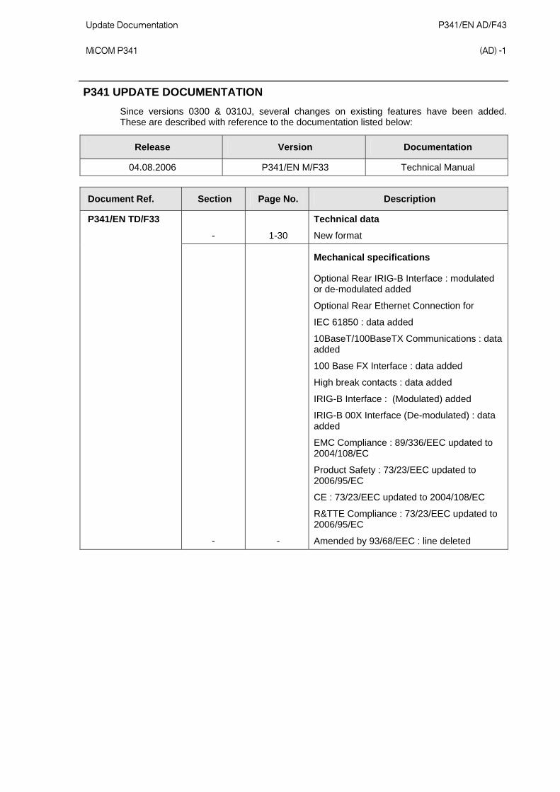
P341 UPDATE DOCUMENTATION
Since versions 0300 & 0310J, several changes on existing features have been added. These are described with reference to the documentation listed below:
Release Version Documentation
04.08.2006 P341/EN M/F33 Technical Manual
Document Ref. Section Page No. Description
P341/EN TD/F33
- 1-30
Technical data
New format
- -
Mechanical specifications
Optional Rear IRIG-B Interface : modulated or de-modulated added
Optional Rear Ethernet Connection for
IEC 61850 : data added
10BaseT/100BaseTX Communications : data added
100 Base FX Interface : data added
High break contacts : data added
IRIG-B Interface : (Modulated) added
IRIG-B 00X Interface (De-modulated) : data added
EMC Compliance : 89/336/EEC updated to 2004/108/EC
Product Safety : 73/23/EEC updated to 2006/95/EC
CE : 73/23/EEC updated to 2004/108/EC
R&TTE Compliance : 73/23/EEC updated to 2006/95/EC
Amended by 93/68/EEC : line deleted
P341/EN AD/F43 Update Documentation (AD) -2
MiCOM P341
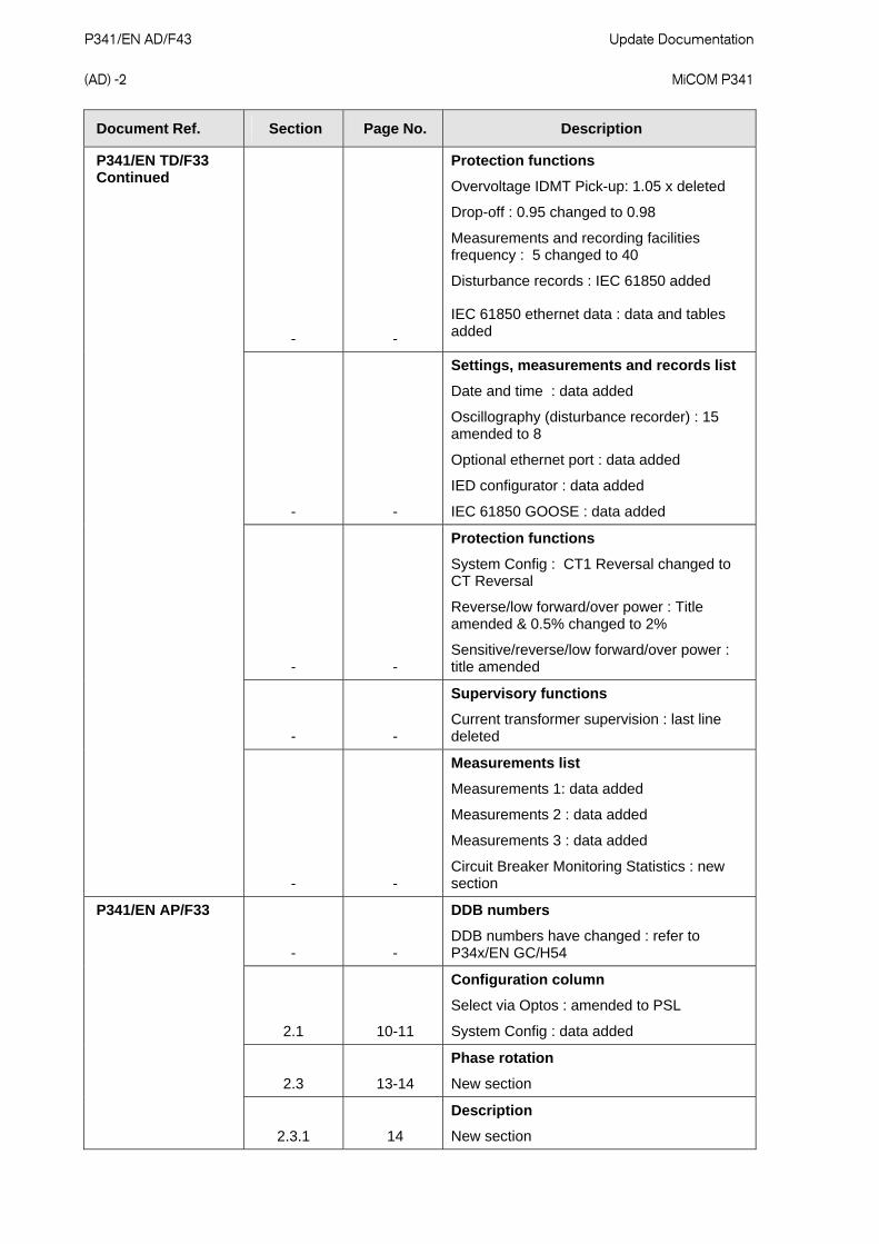
Document Ref. Section Page No. Description
P341/EN TD/F33 Continued
- -
Protection functions
Overvoltage IDMT Pick-up: 1.05 x deleted
Drop-off : 0.95 changed to 0.98
Measurements and recording facilities frequency : 5 changed to 40
Disturbance records : IEC 61850 added
IEC 61850 ethernet data : data and tables added
- -
Settings, measurements and records list
Date and time : data added
Oscillography (disturbance recorder) : 15 amended to 8
Optional ethernet port : data added
IED configurator : data added
IEC 61850 GOOSE : data added
- -
Protection functions
System Config : CT1 Reversal changed to CT Reversal
Reverse/low forward/over power : Title amended & 0.5% changed to 2%
Sensitive/reverse/low forward/over power : title amended
- -
Supervisory functions
Current transformer supervision : last line deleted
- -
Measurements list
Measurements 1: data added
Measurements 2 : data added
Measurements 3 : data added
Circuit Breaker Monitoring Statistics : new section
P341/EN AP/F33
- -
DDB numbers
DDB numbers have changed : refer to P34x/EN GC/H54
2.1 10-11
Configuration column
Select via Optos : amended to PSL
System Config : data added
2.3 13-14
Phase rotation
New section
2.3.1 14
Description
New section

Update Documentation P341/EN AD/F43 MiCOM P341
(AD) -3
Document Ref. Section Page No. Description
P341/EN AP/F33 Continued
2.3.1.1 14
Phase reversal switches affecting all CTs and VTs
New section
Figure 1 : new
Figure 2 : new
2.3.2 14
System config settings
New section
4.9 109 - 110
Disturbance recorder
Paragraph 1 : 3rd sentence amended
Paragraph 3 : amended
Analog channel : table amended and data added
Note : amended
4.11 114
Changing setting groups
Amended to reflect new functionality provided with PSL
4.18 118
Any trip
New section
4.19 118
Date and time
New section
6 124
Auxiliary supply fuse rating
New section
P341/EN SC/F33
9 55
IEC 61850 ethernet interface
New sections
9.1 -
Introduction
New section
9.2 -
What is IEC 61850?
New section
9.21 -
Interoperability
New section
9.2.2 -
The data model
New section
Figure 8 : new
9.3 -
IEC 61850 in MiCOM relays
New section
9.3.1 -
Capability
New section
9.3.2 -
IEC 61850 configuration
New section
9.3.2.1 -
Configuration banks
New section

P341/EN AD/F43 Update Documentation (AD) -4
MiCOM P341
Document Ref. Section Page No. Description
P341/EN SC/F33 continued
9.3.2.2 -
Network connectivity
New section
9.4 -
The data model of MiCOM relays
New section
9.5 -
The communication services of MiCOM relays
New section
9.6 -
Peer-to-peer (GSE) communications
New section
9.6.1 -
Scope
New section
9.6.2 -
IEC 61850 GOOSE configuration
New section
9.7 -
Ethernet functionality
New section
9.7.1 -
Ethernet disconnection
New section
9.7.2 -
Loss of power
New section
P341/EN IN/F33
6.9 13
Ethernet port for IEC 61850
New section
P341/EN HW/F33
1.1.6 4
Ethernet board
New section
Figure 1 : updated
2.4.3 9
High break relay board
New section
Figure 3 : new
2.4.3.1 9
High break contact applications
New section
2.9 12
Ethernet board
New section
Figure 5 : new
P341/EN VH/F33
- -
Firmware and service manual version history
Updated to reflect latest relay software
- 29
Ordering information
Hardware options : data amended
Protocol options : data amended
Design suffix & note design suffix : data amended

Update Documentation P341/EN AD/F43 MiCOM P341
(AD) -1
TECHNICAL DATA (P341/EN TD/F33)

P341/EN AD/F43 Update Documentation (AD) -6
MiCOM P341
Mechanical Specifications
Design Modular MiCOM Px40 platform relay, P341 in 40TE case. Mounting is front of panel flush mounting, or 19“ rack mounted with rack frame (ordering options).
Enclosure Protection Per IEC 60529: 1989: IP 52 Protection (front panel) against dust and dripping water, IP 50 Protection for sides of the case, IP 10 Protection for the rear.
Weight P341 (40TE) :7kg
Terminals
AC Current and Voltage Measuring Inputs Located on heavy duty (black) terminal block: Threaded M4 terminals, for ring lug connection. CT inputs have integral safety shorting, upon removal of the terminal block.
General Input/Output Terminals For power supply, opto inputs, output contacts and RP1 rear communications. Located on general purpose (grey) blocks: Threaded M4 terminals, for ring lug connection.
Case Protective Earth Connection Two rear stud connections, threaded M4. Must be earthed (grounded) for safety, minimum earth wire size 2.5mm2.
Front Port Serial PC Interface EIA(RS)232 DCE, 9 pin D-type female connector Socket SK1. Courier protocol for interface to MiCOM S1 software. Isolation to ELV (extra low voltage) level. Maximum cable length 15m.
Front Download/Monitor Port EIA(RS)232, 25 pin D-type female connector Socket SK2. For firmware and menu text downloads. Isolation to ELV level.
Rear Communications Port (RP1) EIA(RS)485 signal levels, two wire connections located on general purpose block, M4 screw. For screened twisted pair cable, multidrop, 1000m max. For K-Bus, IEC-60870-5-103, MODBUS or DNP3.0 protocol (ordering options). Isolation to SELV (safety extra low low voltage) level.
Optional Rear Fiber Connection for SCADA/DCS BFOC 2.5 -(ST®)-interface for glass fiber, as per IEC 874-10. 850nm short-haul fibers, one Tx and one Rx. For Courier, IEC-60870-5-103, MODBUS or DNP3.0 (Ordering options).
Optional Second Rear Communications Port (RP2) EIA(RS)232, 9 pin D-type female connector, socket SK4. Courier protocol: K-Bus, EIA(RS)232, or EIA(RS)485 connection. Isolation to SELV level.
Optional Rear IRIG-B Interface modulated or de-modulated BNC plug Isolation to SELV level. 50 ohm coaxial cable.
Optional Rear Ethernet Connection for IEC 61850
10BaseT/100BaseTX Communications Interface in accordance with IEEE802.3 and IEC 61850 Isolation: 1.5kV Connector type: RJ45 Cable type: Screened Twisted Pair (STP) Max. cable length: 100m
100 Base FX Interface Interface in accordance with IEEE802.3 and IEC 61850 Wavelength: 1300nm Fiber: multi-mode 50/125µm or 62.5/125µm Connector type: BFOC 2.5 - (ST®)
Ratings
AC Measuring Inputs Nominal frequency: 50 and 60 Hz (settable) Operating range: 40 to 70 Hz
Update Documentation P341/EN AD/F43 MiCOM P341
(AD) -7
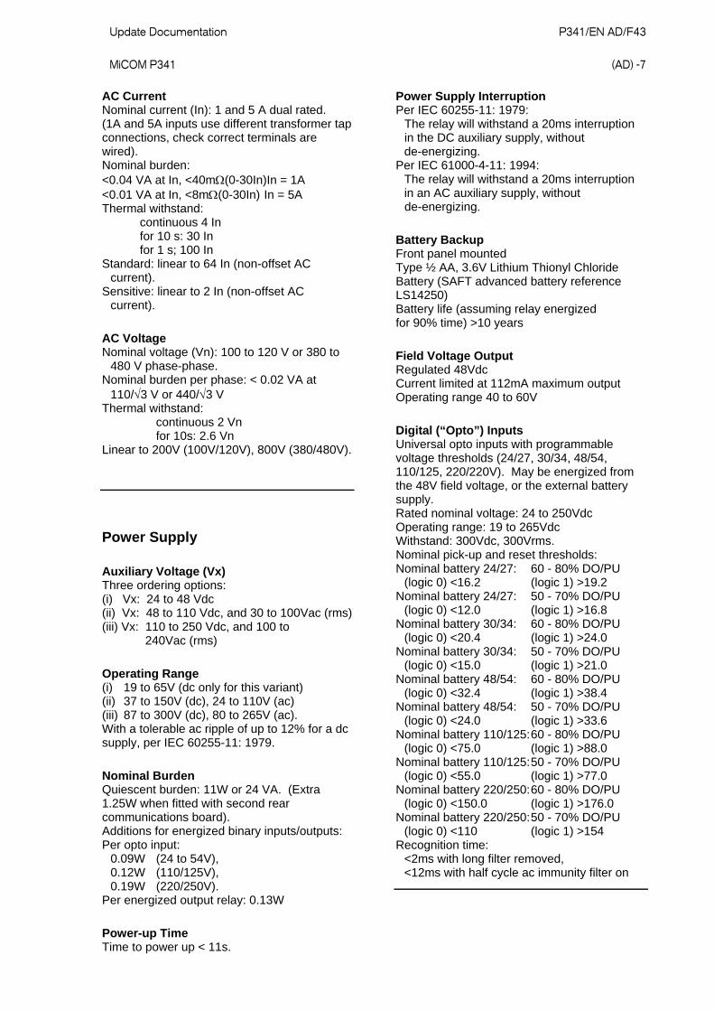
AC Current Nominal current (In): 1 and 5 A dual rated. (1A and 5A inputs use different transformer tap connections, check correct terminals are wired). Nominal burden: <0.04 VA at In, <40m(0-30In)In = 1A <0.01 VA at In, <8m(0-30In) In = 5A Thermal withstand: continuous 4 In for 10 s: 30 In for 1 s; 100 In Standard: linear to 64 In (non-offset AC current). Sensitive: linear to 2 In (non-offset AC current).
AC Voltage Nominal voltage (Vn): 100 to 120 V or 380 to 480 V phase-phase. Nominal burden per phase: < 0.02 VA at 110/3 V or 440/3 V Thermal withstand: continuous 2 Vn for 10s: 2.6 Vn Linear to 200V (100V/120V), 800V (380/480V).
Power Supply
Auxiliary Voltage (Vx) Three ordering options: (i) Vx: 24 to 48 Vdc (ii) Vx: 48 to 110 Vdc, and 30 to 100Vac (rms) (iii) Vx: 110 to 250 Vdc, and 100 to 240Vac (rms)
Operating Range (i) 19 to 65V (dc only for this variant) (ii) 37 to 150V (dc), 24 to 110V (ac) (iii) 87 to 300V (dc), 80 to 265V (ac). With a tolerable ac ripple of up to 12% for a dc supply, per IEC 60255-11: 1979.
Nominal Burden Quiescent burden: 11W or 24 VA. (Extra 1.25W when fitted with second rear communications board). Additions for energized binary inputs/outputs: Per opto input: 0.09W (24 to 54V), 0.12W (110/125V), 0.19W (220/250V). Per energized output relay: 0.13W
Power-up Time Time to power up < 11s.
Power Supply Interruption Per IEC 60255-11: 1979:
The relay will withstand a 20ms interruption in the DC auxiliary supply, without de-energizing.
Per IEC 61000-4-11: 1994: The relay will withstand a 20ms interruption in an AC auxiliary supply, without de-energizing.
Battery Backup Front panel mounted Type ½ AA, 3.6V Lithium Thionyl Chloride Battery (SAFT advanced battery reference LS14250) Battery life (assuming relay energized for 90% time) >10 years
Field Voltage Output Regulated 48Vdc Current limited at 112mA maximum output Operating range 40 to 60V
Digital (“Opto”) Inputs Universal opto inputs with programmable voltage thresholds (24/27, 30/34, 48/54, 110/125, 220/220V). May be energized from the 48V field voltage, or the external battery supply. Rated nominal voltage: 24 to 250Vdc Operating range: 19 to 265Vdc Withstand: 300Vdc, 300Vrms. Nominal pick-up and reset thresholds: Nominal battery 24/27: 60 - 80% DO/PU (logic 0) <16.2 (logic 1) >19.2 Nominal battery 24/27: 50 - 70% DO/PU (logic 0) <12.0 (logic 1) >16.8 Nominal battery 30/34: 60 - 80% DO/PU (logic 0) <20.4 (logic 1) >24.0 Nominal battery 30/34: 50 - 70% DO/PU (logic 0) <15.0 (logic 1) >21.0 Nominal battery 48/54: 60 - 80% DO/PU (logic 0) <32.4 (logic 1) >38.4 Nominal battery 48/54: 50 - 70% DO/PU (logic 0) <24.0 (logic 1) >33.6 Nominal battery 110/125: 60 - 80% DO/PU (logic 0) <75.0 (logic 1) >88.0 Nominal battery 110/125: 50 - 70% DO/PU (logic 0) <55.0 (logic 1) >77.0 Nominal battery 220/250: 60 - 80% DO/PU (logic 0) <150.0 (logic 1) >176.0 Nominal battery 220/250: 50 - 70% DO/PU (logic 0) <110 (logic 1) >154 Recognition time: <2ms with long filter removed, <12ms with half cycle ac immunity filter on

P341/EN AD/F43 Update Documentation (AD) -8
MiCOM P341
Output Contacts
Standard Contacts General purpose relay outputs for signaling, tripping and alarming: Rated voltage: 300 V Continuous current: 10 A Short-duration current: 30 A for 3 s Making capacity: 250A for 30 ms Breaking capacity: DC: 50W resistive DC: 62.5W inductive (L/R = 50ms) AC: 2500VA resistive (cos = unity) AC: 2500VA inductive (cos = 0.7) AC: 1250VA inductive (cos = 0.5) Subject to maxima of 10A and 300V Response to command: < 5ms Durability: Loaded contact: 10 000 operations
minimum, Unloaded contact: 100 000 operations
minimum.
High Break Contacts Relay outputs for tripping: Rated voltage: 300 V Continuous current: 10 A dc Short-duration current: 30 A dc for 3 s Making capacity: 250A dc for 30 ms Breaking capacity: DC: 7500W resistive DC: 2500W inductive (L/R = 50ms) Subject to maxima of 10A and 300V Response to command: < 0.2ms Durability: Loaded contact: 10 000 operations minimum, Unloaded contact: 100 000 operations minimum.
Watchdog Contacts Non-programmable contacts for relay healthy/relay fail indication: Breaking capacity: DC: 30W resistive DC: 15W inductive (L/R = 40ms) AC: 375VA inductive (cos = 0.7)
IRIG-B Interface (Modulated) External clock synchronization per IRIG standard 200-98, format B12x Input impedance 6k at 1000Hz Modulation ratio: 3:1 to 6:1 Input signal, peak-peak: 200mV to 20V
IRIG-B 00X Interface (De-modulated) External clock synchronization per IRIG standard 200-98, format B00X. Input signal TTL level Input impedance at dc 10k
Environmental Conditions
Ambient Temperature Range Per IEC 60255-6: 1988: Operating temperature range: -25°C to +55°C (or -13°F to +131°F) Storage and transit: -25°C to +70°C (or -13°F to +158°F)
Ambient Humidity Range Per IEC 60068-2-3: 1969: 56 days at 93% relative humidity and +40 °C Per IEC 60068-2-30: 1980
Damp heat cyclic, six (12 + 12) hour cycles, 93% RH, +25 to +55 °C
Type Tests
Insulation Per IEC 60255-5: 2000: Insulation resistance > 100M at 500Vdc (Using only electronic/brushless insulation tester).
Creepage Distances and Clearances IEC 60255-27: 2005 Pollution degree 3, Overvoltage category III, Impulse test voltage 5 kV.
High Voltage (Dielectric) Withstand (i) Per IEC 60255-5: 2000, 2 kV rms AC, 1 minute: Between all independent circuits. Between independent circuits and protective (earth) conductor terminal.
1kV rms AC for 1 minute, across open watchdog contacts. 1kV rms AC for 1 minute, across open contacts of changeover output relays. 1kV rms AC for 1 minute for all D-type EIA(RS)232/EIA(RS)485 ports between the communications port terminals and protective (earth) conductor terminal.
(ii) Per ANSI/IEEE C37.90-1989 (reaffirmed 1994): 1.5 kV rms AC for 1 minute, across open contacts of normally open output relays. 1kV rms AC for 1 minute, across open watchdog contacts. 1kV rms AC for 1 minute, across open contacts of changeover output relays.
Impulse Voltage Withstand Test Per IEC 60255-5: 2000: Front time: 1.2 µs, Time to half-value: 50 µs, Peak value: 5 kV, 0.5J

Update Documentation P341/EN AD/F43 MiCOM P341
(AD) -9
Between all independent circuits. Between all independent circuits and protective (earth) conductor terminal.
Between the terminals of independent circuits. EIA(RS)232 & EIA(RS)485 ports and normally open contacts of output relays excepted.
Electromagnetic Compatibility (EMC)
1 MHz Burst High Frequency Disturbance Test Per IEC 60255-22-1: 1988, Class III, Common-mode test voltage: 2.5 kV, Differential test voltage: 1.0 kV, Test duration: 2 s, Source impedance: 200 (EIA(RS)232 ports excepted).
Immunity to Electrostatic Discharge Per IEC 60255-22-2: 1996, Class 4,
15kV discharge in air to user interface, display, communication port and exposed metalwork.
6kV point contact discharge to any part of the front of the product.
Electrical Fast Transient or Burst Requirements Per IEC 60255-22-4: 2002 and EN61000-4-4:2004. Test severity Class III and IV: Amplitude: 2 kV, burst frequency 5kHz (Class III), Amplitude: 4 kV, burst frequency 2.5kHz (Class IV). Applied directly to auxiliary supply, and applied to all other inputs. (EIA(RS)232 ports excepted). Amplitude: 4 kV, burst frequency 5 kHz (Class IV) applied directly to auxiliary.
Surge Withstand Capability Per IEEE/ANSI C37.90.1: 2002: 4kV fast transient and 2.5kV oscillatory applied directly across each output contact, optically isolated input, and power supply circuit.
Surge Immunity Test (EIA(RS)232 ports excepted). Per IEC 61000-4-5: 1995 Level 4, Time to half-value: 1.2 / 50 µs,
Amplitude: 4kV between all groups and protective (earth) conductor terminal. Amplitude: 2kV between terminals of each group.
Immunity to Radiated Electromagnetic Energy Per IEC 60255-22-3: 2000, Class III: Test field strength, frequency band 80 to 1000 MHz: 10 V/m, Test using AM: 1 kHz / 80%, Spot tests at 80, 160, 450, 900 MHz Per IEEE/ANSI C37.90.2: 2004: 80MHz to 1000MHz, 1kHz 80% AM and AM pulsed modulated. Field strength of 35V/m.
Radiated Immunity from Digital Communications Per EN61000-4-3: 2002, Level 4: Test field strength, frequency band 800 to 960 MHz, and 1.4 to 2.0 GHz: 30 V/m, Test using AM: 1 kHz/80%.
Radiated Immunity from Digital Radio Telephones Per IEC61000-4-3: 2002: 10 V/m, 900MHz and 1.89GHz.
Immunity to Conducted Disturbances Induced by Radio Frequency Fields Per IEC 61000-4-6: 1996, Level 3, Disturbing test voltage: 10 V.
Power Frequency Magnetic Field Immunity Per IEC 61000-4-8: 1994, Level 5, 100A/m applied continuously, 1000A/m applied for 3s. Per IEC 61000-4-9: 1993, Level 5, 1000A/m applied in all planes. Per IEC 61000-4-10: 1993, Level 5,
100A/m applied in all planes at 100kHz/1MHz with a burst duration of 2s.
Conducted Emissions Per EN 55022: 1998 Class A:
0.15 - 0.5MHz, 79dBV (quasi peak) 66dBV (average) 0.5 - 30MHz, 73dBV (quasi peak) 60dBV (average).
Radiated Emissions Per EN 55022: 1998 Class A:
30 - 230MHz, 40dBV/m at 10m measurement distance 230 - 1GHz, 47dBV/m at 10m measurement distance.

P341/EN AD/F43 Update Documentation (AD) -10
MiCOM P341
EU Directives
EMC Compliance Per 2004/108/EC: Compliance to the European Commission Directive on EMC is claimed via the Technical Construction File route. Product Specific Standards were used to establish conformity: EN50263: 2000
Product Safety Per 2006/95/EC: Compliance with European Commission Low Voltage Directive. Compliance is demonstrated by reference to generic safety standards: EN60255-27: 2005 EN60255-5: 2001
2004/108/EC:
R&TTE Compliance Radio and Telecommunications Terminal Equipment (R & TTE) directive 95/5/EC. Compliance demonstrated by compliance to the Low Voltage Directive, 2006/95/EC: down to zero volts by reference to safety standards. Applicable to rear communications ports.
ATEX Compliance ATEX Potentially Explosive Atmospheres directive 94/9/EC, for equipment. The equipment is compliant with Article 1(2) of European directive 94/9/EC. It is approved for operation outside an ATEX hazardous area. It is however approved for connection to Increased Safety, “Ex e”, motors with rated ATEX protection, Equipment Category 2, to ensure their safe operation in gas Zones 1 and 2 hazardous areas. CAUTION - Equipment with this marking is not itself suitable for operation within a potentially explosive atmosphere. Compliance demonstrated by Notified Body certificates of compliance.
II (2) G
Mechanical Robustness
Vibration Test Per IEC 60255-21-1: 1996: Response Class 2 Endurance Class 2
Shock and Bump Per IEC 60255-21-2: 1996: Shock response Class 2 Shock withstand Class 1 Bump Class 1
Seismic Test Per IEC 60255-21-3: 1995: Class 2
P34x THIRD PARTY COMPLIANCES (UL/CUL, ENA)
File Number: E202519 Original Issue Date: 05-10-2002 (Complies with Canadian and US requirements).
Certificate Number: 104 Issue 2 Assessment Date: 16-04-2004
Protection Functions
Reverse/Low Forward/Over Power
Accuracy Pick-up: Setting 10% Reverse/Over Power Drop-off: 0.95 of setting 10% Low forward power Drop-off: 1.05 of setting 10% Angle variation Pick-up: Expected pick-up angle 2 degree Angle variation Drop-off: Expected drop-off angle 2.5 degree Operating time: 2% or 50ms whichever is greater Repeatability: <5% Disengagement time: <50ms tRESET: 5% Instantaneous operating time: <50ms

Update Documentation P341/EN AD/F43 MiCOM P341
(AD) -11
Sensitive/Low Forward/Over Power
Accuracy Pick-up: Setting 10% Reverse/Over power Drop-off: 0.9 of setting 10% Low forward power Drop-off: 1.1 of Setting 10% Angle variation Pick-up: Expected pick-up angle 2 degree Angle variation Drop-off: Expected drop-off angle 2.5% degree Operating time: 2% or 50ms whichever is greater Repeatability: <5% Disengagement time: <50ms tRESET: 5% Instantaneous operating time: <50ms
Directional/Non-Directional Overcurrent
Accuracy Pick-up: Setting 5% Drop-off: 0.95 x Setting 5% Minimum trip level (IDMT): 1.05 x Setting 5% IDMT characteristic shape: 5% or 40ms whichever is greater* IEEE reset: 5% or 50ms whichever is greater DT operation: 2% or 50ms whichever is greater DT Reset: 5% Directional accuracy (RCA 90): 2 hysteresis 2 Characteristic UK: IEC 6025-3…1998 Characteristic US: IEEE C37.112…1996 * Under reference conditions
Negative Phase Sequence Overcurrent
Accuracy I2>Pick-up: Setting 5% I2> Drop-off: 0.95 x Setting 5% Vpol Pick-up: Setting 5% Vpol Drop-off: 0.95 x Setting 5% DT operation: 2% or 60ms whichever is greater Disengagement time: <35ms Directional accuracy (RCA 90): 2 hysteresis <1% Repeatability (operating times): <10ms
Thermal Overload
Accuracy Setting accuracy: 5% Reset: 95% of thermal setting 5% Thermal alarm Pick-up: Calculated trip time 5% Thermal overload Pick-up: Calculated trip time 5% Cooling time accuracy: 5% of theoretical Repeatability: <2.5%
Directional/Non-Directional Earth Fault
Earth Fault Accuracy Pick-up: Setting 5% Drop-off: >0.85 x Setting 5% IDMT trip level elements: 1.05 x Setting 5% IDMT characteristic shape: 5% or 40ms whichever is greater* IEEE reset: 5% or 40ms whichever is greater DT operation: 2% or 50ms whichever is greater DT reset: 5% Repeatability: 5%
SEF Accuracy Pick-up: Setting 5% Drop-off: 0.95 x Setting 5% IDMT trip level elements: 1.05 x Setting 5% IDMT characteristic shape: 5% or 40ms whichever is greater* IEEE reset: 7.5% or 60ms whichever is greater DT operation: 2% or 50ms whichever is greater DT reset: 5% Repeatability: 5%
Wattmetric SEF Accuracy P = 0W Pick-up: ISEF> 5% P > 0W Pick-up: P> 5% P = 0W Drop-off: (0.95 x ISEF>) 5% P > 0W Drop-off: 0.9 x P> 5% Boundary accuracy: 5% with 1 hysteresis Repeatability: 5%
Zero Sequence Polarizing Quantities Accuracy Operating boundary Pick-up: 2 of RCA 90 Hysteresis: <3 Vnpol Pick-up: Setting 10% Vnpol Drop-off: 0.9 x Setting or 0.7V (whichever is greater) 10%

P341/EN AD/F43 Update Documentation (AD) -12
MiCOM P341
Negative Sequence Polarizing Quantities Accuracy Operating boundary Pick-up: 2 of RCA 90 Hysteresis: <3 V2pol Pick-up: Setting 10% V2pol Drop-off: 0.9 x Setting or 0.7V (whichever is greater) 10% I2pol Pick-up: Setting 10% I2pol Drop-off: 0.9 x Setting 10%
Restricted Earth Fault
Accuracy Pick-up: Setting formula 5% Drop-off: 0.80 (or better) of calculated differential current High impedance Pick-up: Setting 5% High impedance operating time: <30ms
Transient Overreach and Overshoot
Accuracy Additional tolerance X/R ratios: 5% over the X/R ratio of 1…90 Overshoot of overcurrent elements: <40ms Disengagement time: <60ms (65ms SEF)
Neutral Displacement/Residual Overvoltage
Accuracy DT/IDMT Pick-up: Setting 5% Drop-off: 0.95 x Setting 5% IDMT characteristic shape: 5% or 55ms whichever is greater DT operation: 2% or 55ms whichever is greater Instantaneous operation <55ms Reset: <35ms Repeatability: <1%
df/dt
Accuracy Pick-up: Setting 0.5Hz/s Operating time: 2% or 160ms whichever is greater Lower/Upper dead band operating time: 2% or 160ms whichever is greater Operation over dead band: 2% or 170ms whichever is greater Repeatability: <5%
Voltage Vector Shift
Accuracy Pick-up: Setting 0.5 Trip pulse time: 500ms 2%
Reconnect Delay
Accuracy Operating time: 2% or 50ms whichever is greater
Undervoltage
Accuracy DT Pick-up: Setting 5% IDMT Pick-up: 0.95 x Setting 5% Drop-off: 1.05 x Setting 5% IDMT characteristic shape: 2% or 50ms whichever is greater DT operation: 2% or 50ms whichever is greater Reset: <75ms Repeatability: <1%
Overvoltage
Accuracy DT Pick-up: Setting 5% IDMT Pick-up: Setting 5% Drop-off: 0.98 x Setting 5% IDMT characteristic shape: 2% or 50ms whichever is greater DT operation: 2% or 50ms whichever is greater Reset: <75ms
NPS Overvoltage
Accuracy Pick-up: Setting 5% Drop-off: 0.95 x Setting 5% Repeatability (operating threshold): <1% DT operation: 2% or 65ms whichever is greater Instantaneous operation: <60 ms Instantaneous operation: (accelerated): <45 ms Disengagement time: <35ms Repeatability (operating times): <10ms
Underfrequency
Accuracy Pick-up: Setting 0.01Hz Drop-off: (Setting +0.025HZ) 0.01Hz DT operation: 2% or 50ms whichever is greater* * The operating will also include a time for the relay to frequency track 20Hz/ second).

Update Documentation P341/EN AD/F43 MiCOM P341
(AD) -13
Overfrequency
Accuracy Pick-up: Setting 0.01Hz Drop-off: (Setting -0.025Hz) 0.01Hz DT operation: 2% or 50ms whichever is greater * * The operating will also include a time for the relay to frequency track 20Hz/ second).
CB Fail
Timer Accuracy Timers: 2% or 40ms whichever is greater Reset time: <30ms
Undercurrent Accuracy Pick-up: 10% or 25mA whichever is greater Operating time: < 12ms (Typical <10ms) Reset: < 15ms (Typical < 10ms)
Supervisory Functions
Voltage Transformer Supervision
Accuracy Fast block operation: <25ms Fast block reset: <30ms Time delay: Setting 2% or 20ms whichever is greater
Current Transformer Supervision
Accuracy IN > Pick-up: Setting 5% VN < Pick-up: Setting 5% IN > Drop-off: 0.9 x Setting 5% VN < Drop-off: (1.05 x Setting) 5% or 1V whichever is greater CTS block operation: < 1 cycle CTS reset: < 35ms
Plant Supervision
CB State Monitoring Control and Condition Monitoring
Accuracy Timers: 2% or 20ms whichever is greater Broken current accuracy: 5%
Programmable Scheme Logic
Accuracy Output conditioner timer: Setting 2% or 50ms whichever is greater Dwell conditioner timer: Setting 2% or 50ms whichever is greater Pulse conditioner timer: Setting 2% or 50ms whichever is greater
Measurements and Recording Facilities
Measurements
Accuracy Current: 0.05…3 In: 1% of reading Voltage: 0.05…2 Vn: 5% of reading Power (W): 0.2…2 Vn, 0.05…3 In: 5% of reading at unity power factor Reactive Power (VArs): 0.2…2 Vn, 0.05…3 In: 5% of reading at zero power factor Apparent Power (VA): 0.2…2 Vn, 0.05…3 In: 5% of reading Energy (Wh): 0.2…2 Vn, 0.2…3 In: 5% of reading at zero power factor Energy (Varh): 0.2…2 Vn, 0.2…3 In: 5% of reading at zero power factor Phase accuracy: 0…360: 5% Frequency: 40…70Hz: 0.025Hz
IRIG-B and Real Time Clock
Performance Year 2000: Compliant Real time accuracy: < 1 second / day
Features Real time 24 hour clock settable in hours, minutes and seconds Calendar settable from January 1994 to December 2092 Clock and calendar maintained via battery after loss of auxiliary supply Internal clock synchronization using IRIG-B Interface for IRIG-B signal is BNC
Current Loop Input and Outputs
Accuracy Current loop input accuracy: 1% of full scale CLI drop-off threshold Under: setting 1% of full scale CLI drop-off threshold Over: setting 1% of full scale

P341/EN AD/F43 Update Documentation (AD) -14
MiCOM P341
CLI sampling interval: 50ms CLI instantaneous operating time: < 250ms CLI DT operating time: 2% setting or 200ms whichever is the greater CLO conversion interval: 50ms CLO latency: < 1.07s or <70ms depending on CLO output parameter’s internal refresh rate - (1s or 0.5 cycle) Current loop output accuracy: 0.5% of full scale Repeatability: <5% CLI - Current Loop Input CLO - Current Loop Output
Other Specifications CLI load resistance 0-1 mA: < 4k CLI load resistance 0-1mA/0-20mA/4 20mA: <300 Isolation between common input channels: zero Isolation between input channels and case earth/other circuits: 2kV rms for 1 minute CLO compliance voltage 0-1mA/0 10mA: 10V CLO compliance voltage 0-20mA/4 20mA: 8.8V Isolation between common output channels: zero Isolation between output channels and case earth/other circuits: 2kV rms for 1 minute
Disturbance Records
Accuracy Magnitude and relative phases: 5% of applied quantities Duration: 2% Trigger Position: 2% (minimum 100ms) Record length: 50 records each 1.5s duration (75s total memory) with 8 analogue channels and 32 digital channels (Courier, MODBUS, DNP 3.0, IEC61850), 8 records each 3s (50Hz) or 2.5s (60Hz) duration (IEC60870-5-103). Event, Fault & Maintenance Records Maximum 512 events in a cyclic memory Maximum 5 fault records Maximum 10 maintenance records
Accuracy Event time stamp resolution 1ms
IEC 61850 Ethernet Data
100 Base FX Interface
Transmitter Optical Characteristics (TA = 0°C to 70°C, VCC = 4.75 V to 5.25 V)
Parameter Sym Min. Typ. Max. Unit
Output Optical Power BOL 62.5/125 µm, NA = 0.275 Fiber EOL
PO -19
-20 -16.8 -14
dBm avg.
Output Optical Power BOL 50/125 µm, NA = 0.20 Fiber EOL
PO -22.5
-23.5 -20.3 -14
dBm avg.
Optical Extinction Ratio
10
-10
%
dB
Output Optical Power at Logic “0” State
PO
(“0”) -45
dBm avg.
BOL - Beginning of life
EOL - End of life
Receiver Optical Characteristics (TA = 0°C to 70°C, VCC = 4.75 V to 5.25 V)
Parameter Sym Min. Typ. Max. Unit
Input Optical Power Minimum at Window Edge
PIN Min. (W)
-33.5 –31 dBm avg.
Input Optical Power Minimum at Eye Center
PIN Min. (C)
-34.5 -31.8 Bm avg.
Input Optical Power Maximum
PIN Max.
-14 -11.8 dBm avg.
Note: The 10BaseFL connection will no longer be supported as IEC 61850 does not specify this interface
Settings, Measurements and Records List
Settings List
Global Settings (System Data) Language: English/French/German/Spanish Frequency: 50/60Hz
Circuit Breaker Control (CB Control): CB Control by: Disabled Local Remote Local+Remote Opto Opto+local Opto+Remote

Update Documentation P341/EN AD/F43 MiCOM P341
(AD) -15
Opto+Rem+local Close Pulse Time: 0.10...10.00s Trip Pulse Time: 0.10…5.00s Man Close t max: 0.01…9999.00s Man Close Delay: 0.01…600.00s CB Healthy Time: 0.01…9999.00s Check Sync. Time: 0.01...9999.00s Reset Lockout by: User Interface/CB Close Man Close RstDly: 0.10...600.00s CB Status Input: None 52A 52B 52A & 52B
Date and Time IRIG-B Sync: Disabled/Enabled Battery Alarm: Disabled/Enabled LocalTime Enable: Disabled/Fixed/Flexible LocalTime Offset: -720 min…720min DST Enable: Disabled/Enabled DST Offset: 30min…60min DST Start: First/Second/Third/Fourth/ Last DST Start Day: Sun/Mon/Tues/Wed/ Thurs/Fri/Sat DST Start Month: Jan/Feb/Mar/Apr/May/Jun/ Jul/Aug/Sept/Oct/Nov/Dec DST Start Mins: 0min…1425min DST End: First/Second/Third/Fourth/ Last DST End Day: Sun/Mon/Tues/Wed/ Thurs/Fri/Sat DST End Month: Jan/Feb/Mar/Apr/May/Jun/ Jul/Aug/Sept/Oct/Nov/Dec DST End Mins: 0min…1425min RP1 Time Zone: UTC/Local RP2 Time Zone: UTC/Local Tunnel Time Zone: UTC/Local
Configuration Setting Group: Select via Menu Select via PSL Active Settings: Group 1/2/3/4 Setting Group 1: Disabled/Enabled Setting Group 2: Disabled/Enabled Setting Group 3: Disabled/Enabled Setting Group 4: Disabled/Enabled System Config: Invisible/Visible Power: Disabled/Enabled Overcurrent: Disabled/Enabled Thermal Overload: Disabled/Enabled Earth Fault: Disabled/Enabled SEF/REF/Spower: Disabled or SEF/REF or
Sensitive Power Residual O/V NVD: Disabled/Enabled df/dt: Disabled/Enabled V Vector Shift: Disabled/Enabled Reconnect Delay: Disabled/Enabled Volt Protection: Disabled/Enabled Freq Protection: Disabled/Enabled
CB Fail: Disabled/Enabled Supervision: Disabled/Enabled Input Labels: Invisible/Visible Output Labels: Invisible/Visible CT & VT Ratios: Invisible/Visible Event Recorder: Invisible/Visible Disturb Recorder: Invisible/Visible Measure’t Setup: Invisible/Visible Comms Settings: Invisible/Visible Commission Tests: Invisible/Visible Setting Values: Primary/Secondary Control Inputs: Invisible/Visible CLIO Inputs: Disabled/Enabled CLIO Outputs: Disabled/Enabled Ctrl I/P Config: Invisible/Visible Ctrl I/P Labels: Invisible/Visible Direct Access: Disabled/Enabled LCD Contrast: 0…31
CT and VT Ratios Main VT Primary: 100...1000000V Main VT Sec'y: 80...140 (100/120V) 320…560V (380/480V) VN VT Primary (P342/3): 100…1000000V VN VT Secondary (P342/3): 80…140V (100/120V) 320…560V (380/480V) Phase CT Primary: 1A…30kA Phase CT Sec'y: 1A/5A SEF CT Primary: 1A…30KA SEF CT Sec’y: 1A/5A
Sequence of Event Recorder (Record Control) Alarm Event: Disabled/Enabled Relay O/P Event: Disabled/Enabled Opto Input Event: Disabled/Enabled General Event: Disabled/Enabled Fault Rec Event: Disabled/Enabled Maint Rec Event: Disabled/Enabled Protection Event: Disabled/Enabled DDB 31 - 0: (up to): DDB 1022 - 992: Binary function link strings, selecting which DDB signals will be stored as events, and which will be filtered out.
Oscillography (Disturbance Recorder) Duration: 0.10…10.50s Trigger Position: 0.0…100.0% Trigger Mode: Single/Extended Analog Channel 1: (up to): Analog Channel 8: Disturbance channels selected from: IA/IB/IC/VA/VB/VC/VN/ISensitive/Frequency Digital Input 1: (up to): Digital Input 32: Selected binary channel assignment from any DDB status point within the relay (opto input, output contact, alarms, starts, trips, controls, logic…).

P341/EN AD/F43 Update Documentation (AD) -16
MiCOM P341
Input 1 Trigger: No Trigger/Trigger/LH (Low to High)/Trigger H/L (High to Low) (up to): Input 32 Trigger: No Trigger/Trigger L/H/Trigger H/L
Measured Operating Data (Measure’t Setup) Default Display: Access Level 3Ph + N Current 3Ph Voltage Power Date and Time Description Plant Reference Frequency Local Values: Primary/Secondary Remote Values: Primary/Secondary Measurement Ref: VA/VB/VC/IA/IB/IC Measurement Mode: 0/1/2/3 Fix Dem Period: 1…99mins Roll Sub Period: 1…99mins Num Sub Periods: 1…15 Remote2 Values: Primary/Secondary
Communications RP1 Address: (Courier or IEC870-5-103): 0…255 RP1 Address: (DNP3.0): 0…65534 RP1 Address: (MODBUS): 1…247 RP1 InactivTimer: 1…30mins RP1 Baud Rate: (IEC870-5-103): 9600/19200 bits/s RP1 Baud Rate: (MODBUS, Courier): 9600/19200/38400 bits/s RP1 Baud Rate: (DNP3.0): 1200/2400/4800/9600/19200/ 38400 bits/s RP1 Parity: Odd/Even/None (MODBUS, DNP3.0) RP1 Meas Period: 1…60s (IEC870-5-103) RP1 PhysicalLink: Copper (EIA(RS)485/K bus) or Fiber Optic RP1 Time Sync: Disabled/Enabled MODBUS IEC Timer: Standard/Reverse RP1 CS103Blocking: Disabled Monitor Blocking Command Blocking RP1 Port Config: (Courier): K Bus EIA485 (RS485) RP1 Comms Mode: (Courier): IEC60870 FT1.2 IEC60870 10-Bit No parity Note: If RP1 Port Config is K Bus the baud rate is fixed at 64 kbits/s
Optional Ethernet Port NIC Tunl Timeout: 1...30mins NIC Link Report: Alarm, Event, None NIC Link Timeout: 0.1...60s
Optional Additional Second Rear Communication (Rear Port2 (RP2)) RP2 Port Config: EIA(RS)232 EIA(RS)485 K-Bus RP2 Comms Mode: IEC60870 FT1.2 IEC60870 10-Bit No parity RP2 Address: 0…255 RP2 InactivTimer: 1…30mins RP2 Baud Rate: 9600/19200/38400 bits/s Note: If RP2 Port Config is K Bus the baud rate is fixed at 64 kbits/s
Commission Tests Monitor Bit 1: (up to): Monitor Bit 8: Binary function link strings, selecting which DDB signals have their status visible in the Commissioning menu, for test purposes Test Mode: Disabled Test Mode Blocked Contacts Test Pattern: Configuration of which output contacts are to be energized when the contact test is applied
Circuit Breaker Condition Monitoring (CB Monitor Setup) Broken I^: 1.0…2.0 I^ Maintenance: Alarm Disabled/Enabled I^ Maintenance: 1…25000 I^ Lockout: Alarm Disabled/Enabled I^ Lockout: 1…25000 No. CB Ops Maint: Alarm Disabled/Enabled No. CB Ops Maint: 1…10000 No. CB Ops Lock: Alarm Disabled/Enabled No. CB Ops Lock: 1…10000 CB Time Maint: Alarm Disabled/Enabled CB Time Maint: 0.005…0.500s CB Time Lockout: Alarm Disabled/Enabled CB Time Lockout: 0.005…0.500s Fault Freq Lock: Alarm Disabled/Enabled Fault Freq Count: 1…9999 Fault Freq Time: 0…9999s
Update Documentation P341/EN AD/F43 MiCOM P341
(AD) -17
Opto Coupled Binary Inputs (Opto Config) Global Nominal V: 24 - 27V 30 - 34V 48 - 54V 110 - 125V 220 - 250V Custom Opto Input 1: (up to): Opto Input #. (# = max. opto no. fitted): Custom options allow independent thresholds to be set per opto, from the same range as above. Opto Filter Control: Binary function link string, selecting which optos will have an extra 1/2 cycle noise filter, and which will not. Characteristics: Standard 60% - 80% 50% - 70%
Control Inputs into PSL (Ctrl. I/P Config.) Hotkey Enabled: Binary function link string, selecting which of the control inputs will be driven from Hotkeys. Control Input 1: Latched/Pulsed (up to): Control Input 32: Latched/Pulsed Ctrl Command 1: (up to): Ctrl Command 32: ON/OFF SET/RESET IN/OUT ENABLED/DISABLED
IED Configurator Switch Conf. Bank: No Action/Switch Banks
IEC 61850 GOOSE GoEna: Disabled/Enabled Test Mode: Disabled/Pass Through/Forced VOP Test Pattern: 0x00000000... 0xFFFFFFFF Ignore Test Flag: No/Yes
Control Input User Labels (Ctrl. I/P Labels) Control Input 1: (up to): Control Input 32: User defined text string to describe the function of the particular control input
Settings in Multiple Groups Note: All settings here onwards apply for setting groups # = 1 to 4.
Protection Functions
System Config. Phase Sequence: Standard ABC/Reverse ACB VT Reversal: No Swap/A-B Swapped/B-C Swapped/C-A Swapped CT Reversal: No Swap/A-B Swapped/B-C Swapped/C-A Swapped
Reverse/Low Forward/Over Power Operating mode: Generating Motoring Power 1 Function: Reverse Low forward Over -P>1 Setting (reverse power/P<1 Setting (Low forward power)/ P>1 Setting (Overpower): 4…300.0W (1A, 100V/120V) 16…1200.0W (1A, 380V/480V) 20…1500.0W (5A, 100V/120V) 80…6000.0W (5A, 380V/480V) Equivalent Range in %Pn 2%…157% Power 1 Time Delay: 0.00…100.0s Power 1 DO Timer: 0.00…100.0s P1 Poledead Inh: Disabled/Enabled Power 2 as Power 1
Sensitive/Reverse/Low Forward/Overpower Operating mode: Generating Motoring Sen Power1 Func: Reverse Low forward Over Sen -P>1 Setting (Reverse Power)/Sen <P Setting (Low Forward Power)/Sen >P Setting (Over Power): 0.3…100.0W (1A, 100/120V) 1.20…400.0W (1A, 380/480V) 1.50…500.0W (5A, 100/120V) 6.0…2000.0W (5A, 380/480V) Equivalent range in %Pn 0.5%…157% Sen Power 1 Delay: 0.00…100.0s Power 1 DO Timer: 0.00…100.0s P1 Poledead Inh: Disabled/Enabled Comp angle C: -5…+5.0 Sen Power2 as Sen Power 1
P341/EN AD/F43 Update Documentation (AD) -18
MiCOM P341
Phase Overcurrent (Overcurrent) Phase O/C: Sub Heading I>1 Function: Disabled DT IEC S Inverse IEC V Inverse IEC E Inverse UK LT Inverse UK Rectifier RI IEEE M Inverse IEEE V Inverse IEEE E Inverse US Inverse US ST Inverse I>1 Direction: Non-Directional Directional Fwd Directional Rev I>1 Current Set: 0.08…4.00 In I>1 Time Delay: 0.00…100.00s I>1 TMS: 0.025…1.200 I>1 Time Dial: 0.01…100.00 I>1 K (RI): 0.10…10.00 I>1 Reset Char: DT/Inverse I>1 tRESET: 0.00…100.00s I>2 as I>1 I>3 Status: Disabled/Enabled I>3 Direction: Non-Directional Directional Fwd Directional Rev I>3 Current Set: 0.08…10.00 In I>3 Time Delay: 0.00…100.00s I>4 as I>3 I> Char Angle: -95…+95 o I >Function Link: Bit 0 = VTS Blocks I>1 Bit 1 = VTS Blocks I>2 Bit 2 = VTS Blocks I>3 Bit 3 = VTS Blocks I>4 Bit 4, 5, 6 & 7 are not used Binary function link string, selecting which overcurrent elements (stages 1 to 4) will be blocked if VTS detection of fuse failure occurs.
Inverse time (IDMT) characteristic
IDMT characteristics are selectable from a choice of four IEC/UK and five IEEE/US curves as shown in the table below.
The IEC/UK IDMT curves conform to the following formula:
t = T x
K
(/s) - 1 + L
The IEEE/US IDMT curves conform to the following formula:
t = TD x
K
(/s) - 1 + L
Where:
t = Operation time K = Constant = Measured current S = Current threshold setting = Constant L = ANSI/IEEE constant (zero for IEC/UK curves) T = Time multiplier setting for IEC/UK curves TD = Time dial setting for IEEE/US curves
IDMT characteristics
IDMT Curve Stand. K L
Standard inverse
IEC 0.14 0.02 0
Very inverse IEC 13.5 1 0
Extremely inverse
IEC 80 2 0
Long time inverse
UK 120 1 0
Rectifier UK 45900 5.6 0
Moderately inverse
IEEE 0.0515 0.02 0.114
Very inverse IEEE 19.61 2 0.491
Extremely inverse
IEEE 28.2 2 0.1217
Inverse US-C08 5.95 2 0.18
Short time inverse
US-C02 0.16758 0.02 0.11858
The IEC extremely inverse curve becomes definite time at currents greater than 20 x setting. The IEC standard, very and long time inverse curves become definite time at currents greater than 30 x setting.
For all IEC/UK curves, the reset characteristic is definite time only.
For all IEEE/US curves, the reset characteristic can be selected as either inverse curve or definite time.
The inverse reset characteristics are dependent upon the selected IEEE/US IDMT curve as shown in the table below.
All inverse reset curves conform to the following formula:
tRESET = TD x S
(1 - M2) in seconds
Where:
TD = Time dial setting for IEEE curves

Update Documentation P341/EN AD/F43 MiCOM P341
(AD) -19
S = Constant M = /s
Curve Description Standard S
Moderately inverse IEEE 4.85
Very inverse IEEE 21.6
Extremely inverse IEEE 29.1
Inverse US 5.95
Short time inverse US 2.261
The RI curve (electromechanical) has been included in the first stage characteristic setting options for Phase Overcurrent and Earth Fault protections. The curve is represented by the following equation:
t = K x
1
0.339 - ( )0.236/M in seconds
With K adjustable from 0.1 to 10 in steps of 0.05
M = /s
�������
������
������
�������
���
��
�
�
�� �� � �
�������������������������
������������������
������ ���� �� �������������� !��"��������������� #$������"��������������� %&������������������
��������
'�(#)�

P341/EN AD/F43 Update Documentation (AD) -20
MiCOM P341
������* �###��� ������"��������������( �###����"��������������+ �###��$������"��������������, %���������������- %���.����������������
/���0����������
������*
�� �� � �
�������������������������
�
�
��
������������������
������(
������-
������+
������,
'�+#)�
NPS Overcurrent 2>1 Status: Disabled/Enabled 2>1 Direction: Non-Directional Directional Fwd Directional Rev 2> Current Set: 0.08…4.00n 2> Time Delay: 0.00…100.00s 2>2/3/4 as for 2>1 2> VTS Block: Bit 0 = VTS Blocks 2>1 Bit 1 = VTS Blocks 2>2 Bit 2 = VTS Blocks 2>3 Bit 3 = VTS Blocks 2>4 Bits 4, 5, 6 & 7 are not used Binary function link string, selecting which NPS overcurrent elements (stages 1 to 4) will be blocked if VTS detection of fuse failure occurs. 2> V2pol Set: 0.5…25.0 (100V 120V) 2…100V (380/480V) 2> Char Angle: -95…+95
Thermal Overload Thermal: Disabled/Enabled Thermal I>: 0.50…2.50 In Thermal Alarm: 20..100%
T-heating: 1…200 minutes T-cooling: 1…200 minutes M Factor: 0…10
The thermal time characteristic is given by:
t = loge (eq2 - P2)/(eq2 - (Thermal >)2) t = . loge ((K2-A2)/(K2-1))
Where:
K = eq/Thermal > A = P/Thermal > t = Time to trip, following application of the overload current, = Heating time constant of the protected plant
eq = Equivalent current Thermal > = Relay setting current P = Steady state pre-load current before application of the overload eq = (1
2 + M22)
1 = Positive sequence current 2 = Negative sequence current M = A user settable constant proportional to the thermal capacity of the machine
Earth Fault IN1>1 Function: Disabled DT IEC S Inverse IEC V Inverse IEC E Inverse UK LT Inverse RI IEEE M Inverse IEEE V Inverse IEEE E Inverse US Inverse US ST Inverse IDG IN1>1 Directional Non-Directional Directional Fwd Directional Rev IN1>1 Current Set: 0.08…4.00 In IN1>1 IDG Is: 1.0…4.0 In IN1>1 Time Delay: 0.00…200.00s IN1>1 TMS: 0.025…1.200 IN1>1 Time Dial: 0.01…100.00 IN1>1 K(RI): 0.10….10.00 IN1>1 IDG Time: 1.00...2.00 IN1>1 Reset Char.: DT/Inverse IN1>1 tRESET: 0.00…100.00s IN1>2 as IN>1 IN1>3 Status: Disabled Enabled IN1>3 Directional:
Update Documentation P341/EN AD/F43 MiCOM P341
(AD) -21
Non-Directional Directional Fwd Directional Rev IN1>3 Current Set: 0.08…32.00 In IN1>3 Time Delay: 0.00…200.00s IN1>4 as IN>3 IN1> Blocking: Binary function link string, selecting which ground overcurrent elements (stages 1 to 4) will be blocked if VTS detection of fuse failure occurs. IN1> Char Angle: -95… +95 o IN1> Polarization: Zero Sequence Neg. Sequence IN1> VNpol Set: 0.5…80.0V (100/110V) 2…320V (380/480V) IN1> V2pol Set: 0.5…25.0V (100/110V) 2…100V (380/480V) IN1> I2pol Set: 0.08…1.00 In The IDG curve is commonly used for time delayed earth fault protection in the Swedish market. This curve is available in stage 1 of the Earth Fault protection.
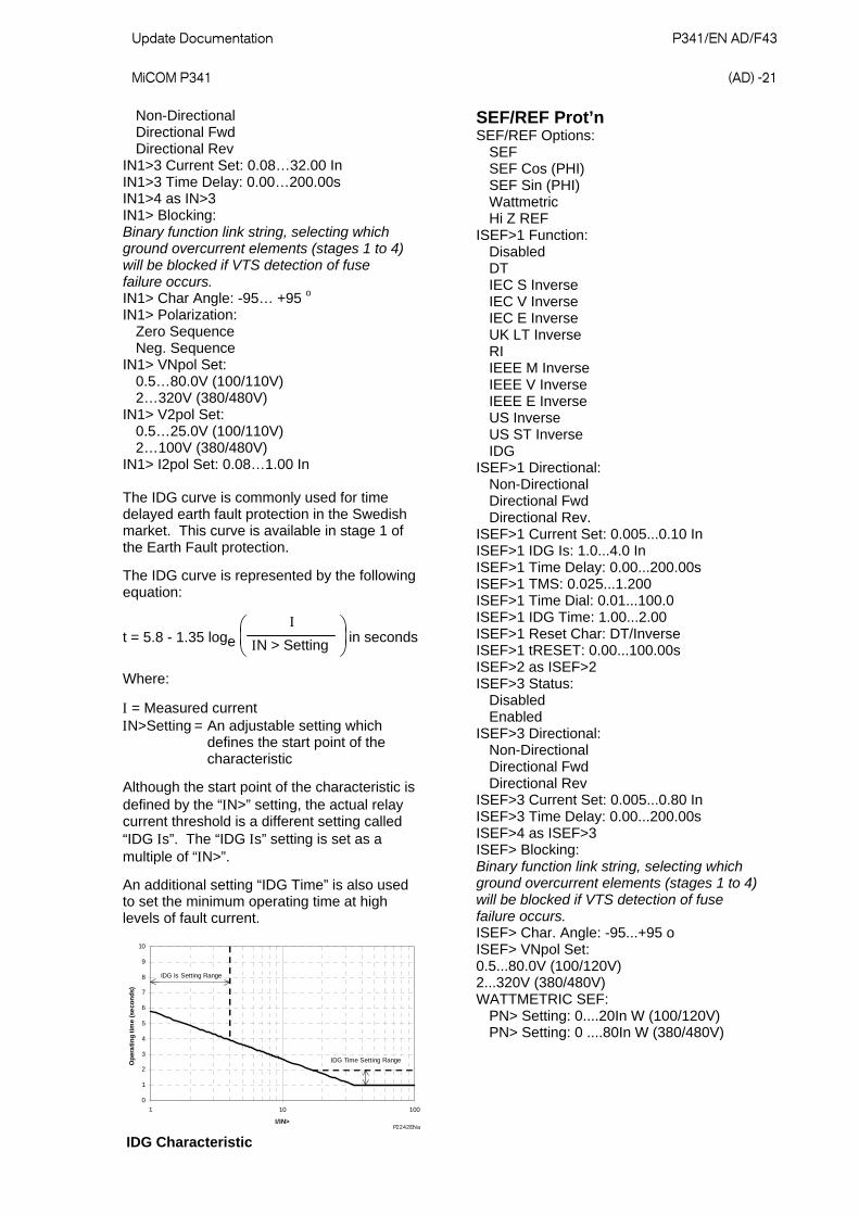
The IDG curve is represented by the following equation:
t = 5.8 - 1.35 loge
N > Setting in seconds
Where:
= Measured current N>Setting = An adjustable setting which defines the start point of the characteristic
Although the start point of the characteristic is defined by the “N>” setting, the actual relay current threshold is a different setting called “IDG s”. The “IDG s” setting is set as a multiple of “N>”.
An additional setting “IDG Time” is also used to set the minimum operating time at high levels of fault current.
0
1
2
3
4
5
6
7
8
9
10
1 10 100
I/IN>
Op
era
tin
g t
ime
(se
con
ds)
IDG Is Setting Range
IDG Time Setting Range
P2242ENa
IDG Characteristic
SEF/REF Prot’n SEF/REF Options: SEF SEF Cos (PHI) SEF Sin (PHI) Wattmetric Hi Z REF ISEF>1 Function: Disabled DT IEC S Inverse IEC V Inverse IEC E Inverse UK LT Inverse RI IEEE M Inverse IEEE V Inverse IEEE E Inverse US Inverse US ST Inverse IDG ISEF>1 Directional: Non-Directional Directional Fwd Directional Rev. ISEF>1 Current Set: 0.005...0.10 In ISEF>1 IDG Is: 1.0...4.0 In ISEF>1 Time Delay: 0.00...200.00s ISEF>1 TMS: 0.025...1.200 ISEF>1 Time Dial: 0.01...100.0 ISEF>1 IDG Time: 1.00...2.00 ISEF>1 Reset Char: DT/Inverse ISEF>1 tRESET: 0.00...100.00s ISEF>2 as ISEF>2 ISEF>3 Status: Disabled Enabled ISEF>3 Directional: Non-Directional Directional Fwd Directional Rev ISEF>3 Current Set: 0.005...0.80 In ISEF>3 Time Delay: 0.00...200.00s ISEF>4 as ISEF>3 ISEF> Blocking: Binary function link string, selecting which ground overcurrent elements (stages 1 to 4) will be blocked if VTS detection of fuse failure occurs. ISEF> Char. Angle: -95...+95 o ISEF> VNpol Set: 0.5...80.0V (100/120V) 2...320V (380/480V) WATTMETRIC SEF: PN> Setting: 0....20In W (100/120V) PN> Setting: 0 ....80In W (380/480V)
P341/EN AD/F43 Update Documentation (AD) -22
MiCOM P341
Restricted Earth Fault (High Impedance) IREF> Is: 0.05.1.00 In
Residual O/V NVD VN>1 Status: Disabled/Enabled VN>1 Input: Derived VN> 1 Function: Disabled DT IDMT VN> 1 Voltage Set: 1…80V (100/120V) 4…320V (380/480V) VN> 1 Time Delay: 0.00…100.00s VN>1 TMS: 0.5…100.0 VN> 1 tRESET: 0.00…100.00 VN>2 as VN>1 VN>3/4 as VN>1 except VN>3/4 Input: VN1
DF/DT df/dt Status: Disabled/Enabled df/dt Setting: 0.1…10 Hz/s df/dt Time Delay: 0.00…100.0s df/dt f low: 45…65Hz df/dt f high: 45…65Hz
V Vector Shift V Shift Status: Disabled/Enabled V Shift Angle: 2…30 o
Reconnect Delay Reconnect Status: Disabled/Enabled Reconnect Delay: 0…300.0s Reconnect tPULSE: 0…10.0s
Voltage Protection
Undervoltage V< Measur’t Mode: Phase-Phase Phase-Neutral V< Operate Mode: Any Phase Three Phase V< 1 Function: Disabled DT IDMT V<1 Voltage Set: 10…120V (100/120v) 40…480V (380/480V) V<1 Time Delay: 0.00…100.00s V<1 TMS: 0.05…100.0 V<1 Poledead Inh: Disabled/Enabled V<2 Function: Disabled DT
V<2 Status: Disabled/Enabled V<2 Voltage Set: 10…120V (100/120V) 40…480V (380/480V) V<2 Time Delay: 0.00…100.00s V<2 Poledead Inh: Disabled/Enabled
The inverse characteristic is given by the following formula:
t = K
(1 - M)
Where:
K = Time multiplier setting t = Operating time in seconds M = Applied input voltage/relay setting voltage
Overvoltage V> Measur’t Mode: Phase-Phase Phase-Neutral V> Operate Mode: Any Phase Three Phase V> 1 Function: Disabled DT IDMT V>1 Voltage Set: 60…185V (100/120V) 240…740V (380/480V) V>1 Time Delay: 0.00…100.00s V>1 TMS: 0.05…100.0 V>2 Status: Disabled/Enabled V>2 Voltage Set: 60…185V (100/120V) 240…740V (380/480V) V>2 Time Delay: 0.00…100.00s
The inverse characteristic is given by the following formula:
t = K
(M - 1)
Where:
K = Time multiplier setting t = Operating time in seconds M = Applied input voltage/relay setting voltage
NPS Overvoltage V2>1 status: Enabled/Disabled V2>1 Voltage Set: 1…150V (100/120V) 4…600V (380/480V) V2>1 Time Delay: 0.00…100.00s

Update Documentation P341/EN AD/F43 MiCOM P341
(AD) -23
Frequency Protection
Underfrequency F<1 Status: Disabled/Enabled F<1 Setting: 45.00…65.00 Hz F<1 Time Delay: 0.1…100.0s F<2/3/4 as F<1 F< Function Link: Bit 0 - Enable Block F<1 during poledead Bit 1 - Enable Block F<2 during poledead Bit 2 - Enable Block F<3 during poledead Bit 3 - Enable Block F<4 during poledead
Overfrequency F>1 Status: Disabled/Enabled F>1 Setting: 45.00…68.00Hz F>1 Time Delay: 0.1…100.0s F>2 as F>1
CB Fail CB Fail 1 Status: Disabled/Enabled CB Fail 1 Timer: 0.00…10.00s CB Fail 2 Status: Disabled/Enabled CB Fail 2 Timer: 0.00…10.00s CBF Non I Reset: I< Only, CB Open & I<, Prot Reset & I< CBF Ext Reset: I< Only, CB Open & I <, Prot Reset & I< I< Current Set: 0.02…3.200In IN< Current Set: 0.02…3.200In ISEF< Current: 0.0010…0.8000In Remove I> Start: Disabled/Enabled Remove IN< Start: Disabled/Enabled I< CT Source: IA-1, IB-1, IC-1/IA-2, IB-2, IC-2
Supervisory Functions
Voltage Transformer Supervison VTS Status: Blocking/Indication VTS Reset Mode: Manual/Auto VTS Time Delay: 1.0…10.0s VTS I> Inhibit: 0.08 In…32.0 In VTS I2> Inhibit: 0.05 In…0.50 In Negative phase sequence voltage (V2): 10V (100/120V) 40V (380/480V) Phase overvoltage: Pick-up 30V, Drop-off 10V (100/120V) Pick-up 120V, Drop-off 40V (380/480v) Superimposed Current: 0.1 In
Current Transformer Supervision CTS 1 Status: Disabled/Enabled CTS 1 VN Input: Measured/Derived CTS 1 VN< Inhibit: 0.5…22V (100/120V) 2…88V (380/480V) CTS 1 IN> Set: 0.08…4In
Plant Supervision
CB State Monitoring Control and Condition Monitoring Broken I^: 1…2.0 I^ Maintenance: Alarm disabled Alarm enabled I^ Maintenance: 1In^…25000In^ I^ Lockout: Alarm disabled Alarm enabled I^ Lockout: 1…25000 No CB Ops. Maint: Alarm disabled Alarm enabled No CB Ops: Maint: 1…10000 No CB Ops Lock: Alarm disabled Alarm enabled No CB Ops Lock: 1…10000 CB Time Maint: Alarm disabled Alarm enabled CB Time Maint: 0.005…0.500s CB Time Lockout: Alarm disabled Alarm enabled CB Time Lockout: 0.005…0.500s Fault Freq Lock: Alarm disabled Alarm enabled Fault Freq Count: 1…9999 Fault Freq Time: 0…9999s
Input Labels Opto Input 1…32: Input L1…Input L32
Output Labels Relay 1…32: Output R1…Output R32
Current Loop Input CLIO1 Input 1: Disabled/Enabled CLI1 Input Type: 0 - 1mA 0 - 10mA 0 - 20mA 4 - 20mA CLI1 Input Label: 16 characters (CLIO input 1)

P341/EN AD/F43 Update Documentation (AD) -24
MiCOM P341
CLI1 Minimum: -9999…+9999 CLI1 Maximum: -9999…+9999 CLI1 Alarm: Disabled/Enabled CLI1 Alarm Fn: Over/Under CLI1 Alarm Set: CLI1 min…CLI1 max CLI1 Alarm Delay: 0.0…100.0s CLI1 Trip: Disabled/Enabled CLI1 Trip Fn: Over/Under CLI1 Trip Set: CLI1 min…CLI1 max CLI1 Trip Delay: 0.0…100.0s CLI1 I< Alarm (4…20 mA input only): Disabled/Enabled CLI1 I< Alm Set (4…20 mA input only): 0.0…4.0mA CLI2/3/4 as CLI1
Current Loop Output CLO1 Output 1: Disabled/Enabled CLO1 Output Type: 0 - 1mA 0 - 10mA 0 - 20mA 4 - 20mA CLO1 Set Values: Primary/Secondary CLO1 Parameter: As shown below* CLO1 Min: Range, step size and unit corresponds to the selected parameter CLO1 Max: Same as CLO1 Min CLO2/3/4 as CLO1 Current Loop Output Parameters Current Magnitude: IA Magnitude IB Magnitude IC Magnitude IN Derived Mag: 0.00…16.0 I Sen Mag: 0.00… 2.0A Phase Sequence Components: I1 Magnitude I2 Magnitude I0 Magnitude: 0.00…16.0A Phase Currents: IA RMS* IB RMS* IC RMS* 0.00…16.0A P-P Voltage Magnitude: VAB Magnitude VBC Magnitude VCA Magnitude 0.0…200.0V P-N Voltage Magnitude: VAN Magnitude VBN Magnitude VCN Magnitude 0.0…200.0V Neutral Voltage Magnitude: VN1 Measured Mag VN Derived Mag 0.0…200.0V Phase Sequence Voltage Components: V1 Magnitude*
V2 Magnitude V0 Magnitude 0.0…200.0V RMS Phase Voltages: VAN RMS* VBN RMS* VCN RMS* 0.0…200.0V Frequency: 0.00…70.0Hz 3 Phase Watts*: -6000W…6000W 3 Phase Vars*: -6000Var…6000Var 3 Phase VA*: 0…6000VA 3Ph Power Factor*: -1…1 Single Phase Active Power: A Phase Watts*: B Phase Watts*: C Phase Watts*: -2000W…2000W Single Phase Reactive Power: A Phase Vars*: B Phase Vars*: C Phase Vars* -2000Var…2000Var Single Phase Apparent Power: A Phase VA*: B Phase VA*: C Phase VA* 0…2000VA Single Phase Power Factor: Aph Power Factor* BPh Power Factor* CPh Power Factor* -1…1 3 Phase Current Demands: IA Fixed/Roll/Peak Demand* IB Fixed/Roll/Peak Demand* IC Fixed/Roll/Peak Demand* 0.00…16.0A 3ph Active Power Demands: 3Ph W Fix/Roll/Peak Demand* -6000W…6000W 3ph Reactive Power Demands: 3Ph Vars Fix/Roll/Peak Dem* -6000Var…6000Var Thermal Overload: 0.00…200.0% CL Input 1-4: -9999…9999.0
Note 1: Measurements marked with an asterisk, the internal refresh rate is nominally 1s, others are 0.5 power system cycles or less. Note 2: The polarity of Watts, Var and power factor is affected by the measurements Mode setting. Note 3: These settings are for nominal 1A and 100/120V versions only. For other versions they need to be multiplied accordingly.

Update Documentation P341/EN AD/F43 MiCOM P341
(AD) -25
Measurements List
Measurements 1 I Magnitude I Phase Angle Per phase ( = A/A-1, B/B-1, C/C-1) current measurements IN Derived Mag IN Derived Angle ISen Mag ISen Angle I1 Magnitude I2 Magnitude I0 Magnitude I RMS Per phase ( = A, B, C) RMS current measurements IN -2 Derived V- Magnitude V- Phase Angle V Magnitude V Phase Angle All phase-phase and phase-neutral voltages ( = A, B, C). VN Measured Mag VN Measured Ang VN Derived Mag V1 Magnitude V2 Magnitude V0 Magnitude V RMS All phase-neutral voltages ( = A, B, C). Frequency I1 Magnitude I1 Angle I2 Magnitude I2 Angle I0 Magnitude I0 Angle V1 Magnitude V1 Angle V2 Magnitude V2 Angle V0 Magnitude V0 Angle
Measurements 2 Phase Watts Phase VArs Phase VA All phase segregated power measurements, real, reactive and apparent ( = A, B, C). 3 Phase Watts 3 Phase VArs 3 Phase VA NPS Power S2
3Ph Power Factor Ph Power Factor Independent power factor measurements for all three phases ( = A, B, C). 3Ph WHours Fwd 3Ph WHours Rev 3Ph VArHours Fwd 3Ph VArHours Rev 3Ph W Fix Demand 3Ph VArs Fix Dem I Fixed Demand Maximum demand currents measured on a per phase basis ( = A, B, C). 3Ph W Roll Dem 3Ph VArs Roll Dem I Roll Demand Maximum demand currents measured on a per phase basis ( = A, B, C). 3Ph W Peak Dem 3Ph VAr Peak Dem I Peak Demand Maximum demand currents measured on a per phase basis ( = A, B, C). Reset Demand: No/Yes
Measurements 3 IREF Diff A Ph Sen Watts A Ph Sen VArs A Phase Power Angle Thermal Overload Reset Thermal O/L: No/Yes CLIO Input 1/2/3/4
Circuit Breaker Monitoring Statistics CB Operations Total I Broken Cumulative breaker interruption duty on a per phase basis ( = A, B, C) CB Operate Time Reset CB Data: No/Yes.

P341/EN AD/F43 Update Documentation (AD) -26
MiCOM P341
APPLICATION NOTES (P341/EN AP/F33)
2.1 Configuration column
The P34x relays include a column in the menu called the “CONFIGURATION” column. This affects the operation of each of the individual protection functions. The aim of this column is to allow general configuration of the relay from a single point in the menu. Any of the functions that are disabled or made invisible from this column do not then appear within the main relay menu.
The following table shows the relay menu for the Configuration column, with default settings. The brief description of the function of each setting is also provided.
Menu Text Default Setting Available Settings Function
CONFIGURATION
Restore Defaults No Operation
No Operation All Settings Setting Group 1 Setting Group 2 Setting Group 3 Setting Group 4
Restore default settings to any or all groups of settings
Setting Group Select via Menu Select via Menu Select via PSL
Change setting groups by
Active Settings Group 1
Group 1 Group 2 Group 3 Group 4
Select active setting group used for protection settings
Save Changes No Operation No Operation Save Abort
Saves all setting changes from stored settings buffer memory into stored settings
Copy From Group 1 Group1, 2, 3 or 4
Selects a group of settings to copy to the group designated in “Copy To” cell
Copy To No Operation Group1, 2, 3 or 4
Copies the group of settings selected in the “Copy From” cell to the selected setting group
Setting Group 1 Enabled Enabled or Disabled Selects if Group 1 settings are available on the relay
Setting Group 2 Disabled Enabled or Disabled Selects if Group 2 settings are available on the relay
Setting Group 3 Disabled Enabled or Disabled Selects if Group 3 settings are available on the relay
Setting Group 4 Disabled Enabled or Disabled Selects if Group 4 settings are available on the relay
System Config Visible Invisible or Visible Makes settings visible in the relay

Update Documentation P341/EN AD/F43 MiCOM P341
(AD) -27
Menu Text Default Setting Available Settings Function
Power Enabled Enabled or Disabled Makes settings visible in the relay menu
Thermal Overload Enabled Enabled or Disabled Makes settings visible in the relay menu
Overcurrent Enabled Enabled or Disabled Makes settings visible in the relay menu
Earth Fault Enabled Enabled or Disabled Makes settings visible in the relay menu
SEF/REF/SPower SEF/REF Disabled or SEF/REF or Sensitive Power
Makes settings visible in the relay menu
Residual O/V NVD Enabled Enabled or Disabled Makes settings visible in the relay menu
df/dt Disabled Enabled or Disabled Makes settings visible in the relay menu
V Vector Shift Disabled Enabled or Disabled Makes settings visible in the relay menu
Reconnect Delay Disabled Enabled or Disabled Makes settings visible in the relay menu
Volt Protection Enabled Enabled or Disabled Makes settings visible in the relay menu
Freq Protection Enabled Enabled or Disabled Makes settings visible in the relay menu
CB Fail Disabled Enabled or Disabled Makes settings visible in the relay menu
Supervision Disabled Enabled or Disabled Makes settings visible in the relay menu
Input Labels Visible Invisible or Visible Makes settings visible in the relay menu
Output Labels Visible Invisible or Visible Makes settings visible in the relay menu
CT & VT Ratios Visible Invisible or Visible Makes settings visible in the relay menu
Event Recorder Invisible Invisible or Visible Makes settings visible in the relay menu
Disturb Recorder Invisible Invisible or Visible Makes settings visible in the relay menu
Measure’t Setup Invisible Invisible or Visible Makes settings visible in the relay menu
Comms Settings Visible Invisible or Visible Makes settings visible in the relay menu
Commission Tests Visible Invisible or Visible Makes settings visible in the relay menu
Setting Values Primary Primary or Secondary
Selects if relay protection settings are displayed in primary or secondary current/voltage values
P341/EN AD/F43 Update Documentation (AD) -28
MiCOM P341
Menu Text Default Setting Available Settings Function
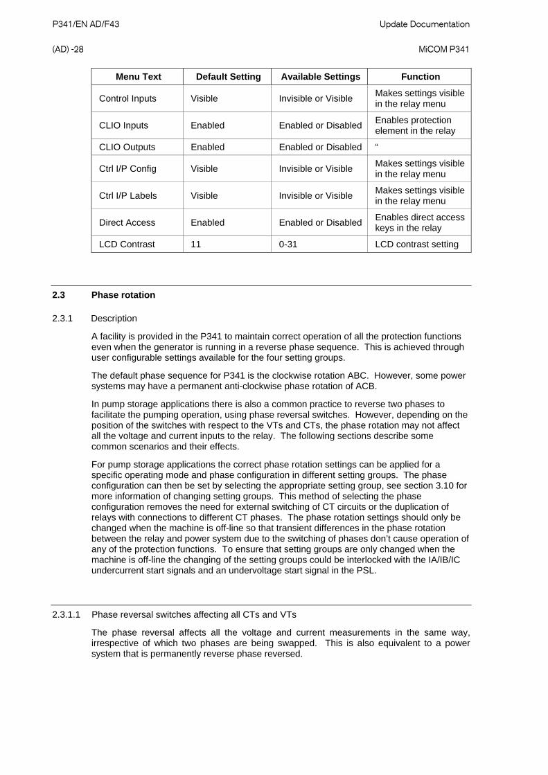
Control Inputs Visible Invisible or Visible Makes settings visible in the relay menu
CLIO Inputs Enabled Enabled or Disabled Enables protection element in the relay
CLIO Outputs Enabled Enabled or Disabled “
Ctrl I/P Config Visible Invisible or Visible Makes settings visible in the relay menu
Ctrl I/P Labels Visible Invisible or Visible Makes settings visible in the relay menu
Direct Access Enabled Enabled or Disabled Enables direct access keys in the relay
LCD Contrast 11 0-31 LCD contrast setting
2.3 Phase rotation
2.3.1 Description
A facility is provided in the P341 to maintain correct operation of all the protection functions even when the generator is running in a reverse phase sequence. This is achieved through user configurable settings available for the four setting groups.
The default phase sequence for P341 is the clockwise rotation ABC. However, some power systems may have a permanent anti-clockwise phase rotation of ACB.
In pump storage applications there is also a common practice to reverse two phases to facilitate the pumping operation, using phase reversal switches. However, depending on the position of the switches with respect to the VTs and CTs, the phase rotation may not affect all the voltage and current inputs to the relay. The following sections describe some common scenarios and their effects.
For pump storage applications the correct phase rotation settings can be applied for a specific operating mode and phase configuration in different setting groups. The phase configuration can then be set by selecting the appropriate setting group, see section 3.10 for more information of changing setting groups. This method of selecting the phase configuration removes the need for external switching of CT circuits or the duplication of relays with connections to different CT phases. The phase rotation settings should only be changed when the machine is off-line so that transient differences in the phase rotation between the relay and power system due to the switching of phases don’t cause operation of any of the protection functions. To ensure that setting groups are only changed when the machine is off-line the changing of the setting groups could be interlocked with the IA/IB/IC undercurrent start signals and an undervoltage start signal in the PSL.
2.3.1.1 Phase reversal switches affecting all CTs and VTs
The phase reversal affects all the voltage and current measurements in the same way, irrespective of which two phases are being swapped. This is also equivalent to a power system that is permanently reverse phase reversed.
Update Documentation P341/EN AD/F43 MiCOM P341
(AD) -29
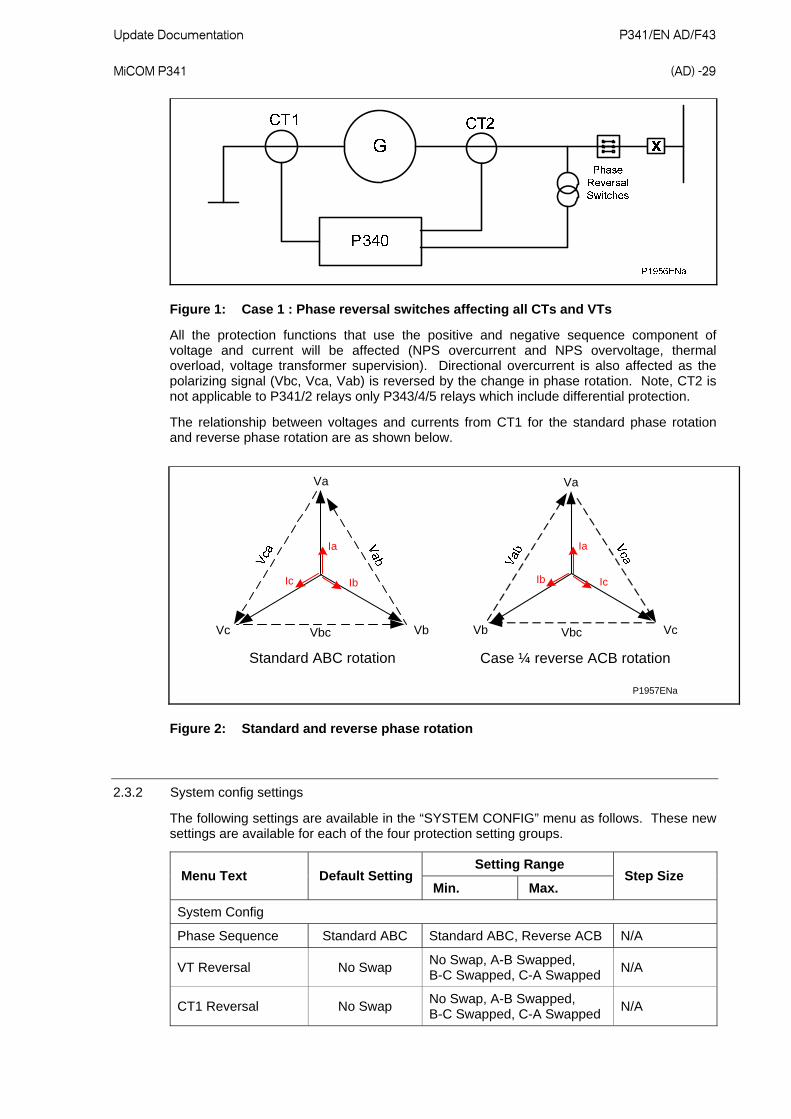
Figure 1: Case 1 : Phase reversal switches affecting all CTs and VTs
All the protection functions that use the positive and negative sequence component of voltage and current will be affected (NPS overcurrent and NPS overvoltage, thermal overload, voltage transformer supervision). Directional overcurrent is also affected as the polarizing signal (Vbc, Vca, Vab) is reversed by the change in phase rotation. Note, CT2 is not applicable to P341/2 relays only P343/4/5 relays which include differential protection.
The relationship between voltages and currents from CT1 for the standard phase rotation and reverse phase rotation are as shown below.
Standard ABC rotation
Vc VbVbc
Va
Ia
IbIc
Case ¼ reverse ACB rotation
Vb VcVbc
Va
Ia
IcIb
P1957ENa
Figure 2: Standard and reverse phase rotation
2.3.2 System config settings
The following settings are available in the “SYSTEM CONFIG” menu as follows. These new settings are available for each of the four protection setting groups.
Setting Range Menu Text Default Setting
Min. Max. Step Size
System Config
Phase Sequence Standard ABC Standard ABC, Reverse ACB N/A
VT Reversal No Swap No Swap, A-B Swapped, B-C Swapped, C-A Swapped
N/A
CT1 Reversal No Swap No Swap, A-B Swapped, B-C Swapped, C-A Swapped
N/A

P341/EN AD/F43 Update Documentation (AD) -30
MiCOM P341
The Phase Sequence setting applies to a power system that has a permanent phase sequence of either ABC or ACB. It is also applicable for temporary phase reversal which affects all the VTs and CTs. As distinct from the other phase reversal settings, this setting does not perform any internal phase swapping of the analogue channels.
The Phase Sequence setting affects the sequence component calculations as follows:
Standard ABC The calculations of positive (I1, V1) and negative (I2, V2) phase sequence voltage and current remain unchanged as follows:
c2
ba1 XXX3
1X
cb2
a2 XXX3
1X
Reverse ACB The calculations of positive (I1, V1) and negative (I2, V2) phase sequence voltage and current are given by the equations:
cb2
a1 XXX3
1X
c2
ba2 XXX3
1X
Where: 1201
The Phase Sequence setting also affects the directional overcurrent protection as follows:
Phase Rotation 67 (Directional Overcurrent)
Standard ABC Phase A use Ia, Vbc
Phase B use Ib, Vca
Phase C use Ic, Vab
Reverse ACB Phase A use Ia, -Vbc
Phase B use Ib, -Vca
Phase C use Ic, -Vab
The VT Reversal and CT1 Reversal settings apply to applications where some or all of the voltage or current inputs are temporarily reversed, as in pump storage applications. The settings affect the order of the analogue channels in the relay and are set to emulate the order of the channels on the power system. So, assuming the settings emulate the change in phase configuration on the power system all the protection functions will naturally operate as per a standard phase rotation system. The phase sequence calculations and the protection functions all remain unchanged.
4.9 Disturbance recorder
The integral disturbance recorder has an area of memory specifically set aside for record storage. The number of records that may be stored by the relay is dependent upon the selected recording duration. The relay can typically store a minimum of 50 records, each of 1.5 seconds duration (8 analog channels and 32 digital channels). VDEW relays, however, have the same total record length but the VDEW protocol dictates that only 8 records (of 3 seconds duration) can be extracted via the rear port. Disturbance records continue to be recorded until the available memory is exhausted, at which time the oldest record(s) are overwritten to make space for the newest one.

Update Documentation P341/EN AD/F43 MiCOM P341
(AD) -31
The recorder stores actual samples which are taken at a rate of 24 samples per cycle.
Each disturbance record consists of a maximum of 8 analog data channels for P341 and thirty-two digital data channels.
Note: The relevant CT and VT ratios for the analog channels are also extracted to enable scaling to primary quantities.
If a CT ratio is set less than unity, the relay will choose a scaling factor of zero for the appropriate channel.
The “DISTURBANCE RECORDER” menu column is shown below:
Setting Range Menu Text Default Setting
Min. Max. Step Size
DISTURBANCE RECORDER
Duration 1.5s 0.1s 10.5s 0.01s
Trigger Position 33.3% 0 100% 0.1%
Trigger Mode Single Single or Extended
Analog Channel 1 VAN Unused, VAN, VBN, VCN, VN1, A, B, C, N, Sensitive, Frequency
Analog Channel 2 VBN As above
Analog Channel 3 VCN As above
Analog Channel 4 VN1 As above
Analog Channel 5 A-1 As above
Analog Channel 6 B-1 As above
Analog Channel 7 C-1 As above
Analog Channel 8 Sensitive As above
Digital Inputs 1 to 32 Any output contact or optical input or internal digital signal
Inputs 1 to 32 Trigger
No Trigger No Trigger, Trigger L/H except Dedicated Trigger H/L Trip Relay O/P’s which are set to Trigger L/H
Note: The available analog and digital signals will differ between relay types and models and so the individual courier database in the Relay Menu Database (P341/EN MD) should be referred to when determining default settings etc.
The pre and post fault recording times are set by a combination of the “Duration” and “Trigger Position” cells. “Duration” sets the overall recording time and the “Trigger Position” sets the trigger point as a percentage of the duration. For example, the default settings show that the overall recording time is set to 1.5s with the trigger point being at 33.3% of this, giving 0.5s pre-fault and 1s post fault recording times.
If a further trigger occurs whilst a recording is taking place, the recorder will ignore the trigger if the “Trigger Mode” has been set to “Single”. However, if this has been set to “Extended”, the post trigger timer will be reset to zero, thereby extending the recording time.
As can be seen from the menu, each of the analog channels is selectable from the available analog inputs to the relay. The digital channels may be mapped to any of the opto isolated inputs or output contacts, in addition to a number of internal relay digital signals, such as protection starts, LED’s etc. The complete list of these signals may be found by viewing the available settings in the relay menu or via a setting file in MiCOM S1. Any of the digital channels may be selected to trigger the disturbance recorder on either a low to high or a

P341/EN AD/F43 Update Documentation (AD) -32
MiCOM P341
high to low transition, via the “Input Trigger” cell. The default trigger settings are that any dedicated trip output contacts (e.g. relay 3) will trigger the recorder.
It is not possible to view the disturbance records locally via the LCD; they must be extracted using suitable software such as MiCOM S1. This process is fully explained in SCADA Communications (P341/EN SC).
4.11 Changing setting groups
The setting groups can be changed either via 2 DDB signals or via a menu selection selection or via the hotkey menu. In the Configuration column if “Setting Group - select via PSL” is selected then DDBs 629 (SG Select 1x) and 628 (SG Select x1), which are dedicated for setting group selection, can be used to select the setting group as shown in the table below. These DDB signals can be connected to opto inputs for local selection or control inputs for remote selection of the setting groups. If “Setting Group - select via menu” is selected then in the Configuration column the “Active Settings - Group1/2/3/4” can be used to select the setting group.
The setting group can be changed via the hotkey menu providing “Setting Group select via menu” is chosen.
SG Select 1x SG Select x1 Selected Setting Group
0 0 1
1 0 2
0 1 3
1 1 4
Note: Setting groups comprise both Settings and Programmable Scheme Logic. Each is independent per group - not shared as common. The settings are generated in the Settings and Records application within MiCOM S1, or can be applied directly from the relay front panel menu. The programmable scheme logic can only be set using the PSL Editor application within MiCOM S1, generating files with extension ".psl". It is essential that where the installation needs application-specific PSL, that the appropriate .psl file is downloaded (sent) to the relay, for each and every setting group that will be used. If the user fails to download the required .psl file to any setting group that may be brought into service, then factory default PSL will still be resident. This may have severe operational and safety consequences.
4.18 Any trip
The “Any Trip” DDB (DDB 626) has been made independent from Relay 3 in the version 32 software. In Previous versions of software the “Any Trip” signal was the operation of Relay 3. In the version 32 software DDB 626 is the “Any Trip” signal and any output contact used for tripping can be connected to the “Any Trip” DDB leaving Relay 3 to be freely assigned for any function. The “Any Trip” signal affects the following functions:
Operates the Trip LED
Triggers CB condition maintenance counters
Used to measure the CB operating time
Triggers the circuit breaker failure logic
Used in the Fault recorder logic

Update Documentation P341/EN AD/F43 MiCOM P341
(AD) -33
In the default PSL, Relay 3 is still mapped to the “Any Trip” DDB and the “Fault REC TRIG” DDB signals. If the user wants to make use of the CB maintenance features, CB failure function etc. they should map the output contact(s) assigned for tripping the monitored circuit breaker to the “Any Trip” DDB. The output contact(s) assigned for tripping the monitored circuit breaker should also be connected to the fault record trigger “Fault REC TRIG” DDB 623 for fault record triggering.
Note, where relay 3 or any other contact is used to initiate the “Any Trip” signal the contact should not be set to latched as the “Any Trip” is used to trigger (on pick-up) and reset (on drop-off) the fault recorder window. So if the “Any Trip” is latched the fault recording window never resets and so you won’t see a fault record on the relay front display as the relay thinks the fault is still present.
The default setting for relay 3 is a dwell time of 100ms, a dwell is the minimum time the contact will be ON and is used for trip functions to ensure a good quality trip signal is obtained. As an example of a dwell timer, a dwell of 100ms means that if the initiating signal is ON for 10ms then the output contact is ON for 100ms and if the initiating signal is ON for 200ms then the output contact is ON for 200ms.
4.19 Date and time
Displays the date and time as well as the battery condition.
Setting Range Menu Text Default Setting
Min. Max. Step Size
DATE AND TIME
Date/Time Data
Displays the relay’s current date and time.
IRIG-B Sync. Disabled Disabled or Enabled N/A
Enables or disables the IRIG-B time synchronization.
IRIG-B Status Data Card not fitted/Card failed/ Signal healthy/No signal
N/A
Displays the status of IRIG-B.
Battery Status Dead or Healthy
Displays whether the battery is healthy or not.
Battery Alarm Enabled Disabled or Enabled N/A
Enables or disables battery alarm. The battery alarm needs to be disabled when a battery is removed or not used.
SNTP Status Data
Disabled/Trying Server1/ Trying Server 2/Server 1
OK/Server 2 OK/No response/No Valid Clock
N/A
Displays information about the SNTP time synchronization status

P341/EN AD/F43 Update Documentation (AD) -34
MiCOM P341
Setting Range Menu Text Default Setting
Min. Max. Step Size
LocalTime Enable Fixed Disabled/Fixed/ Flexible N/A
Setting to turn on/off local time adjustments.
Disabled - No local time zone will be maintained. Time synchronization from any interface will be used to directly set the master clock and all displayed (or read) times on all interfaces will be based on the master clock with no adjustment.
Fixed - A local time zone adjustment can be defined using the LocalTime offset setting and all interfaces will use local time except SNTP time synchronization and IEC61850 timestamps.
Flexible - A local time zone adjustment can be defined using the LocalTime offset setting and each interface can be assigned to the UTC zone or local time zone with the exception of the local interfaces which will always be in the local time zone and IEC61850/SNTP which will always be in the UTC zone.
LocalTime Offset 0 min -720 min 720 min 1 min
Setting to specify an offset of -12 to +12 hrs in 15 minute intervals for local time zone. This adjustment is applied to the time based on the master clock which is UTC/GMT
DST Enable Enabled Disabled or Enabled N/A
Setting to turn on/off daylight saving time adjustment to local time.
DST Offset 60 min 30 min 60 min 30 min
Setting to specify daylight saving offset which will be used for the time adjustment to local time.
DST Start Last First/Second/Third/Fourth/
Last N/A
Setting to specify the week of the month in which daylight saving time adjustment starts
DST Start Day Sunday Sunday/Monday/Tuesday/
Wednesday/Thursday/ Friday/Saturday
N/A
Setting to specify the day of the week in which daylight saving time adjustment starts
DST Start Month March
January/February/March/ April/May/June/July/August/
September/November/ December
N/A
Setting to specify the month in which daylight saving time adjustment starts
DST Start Mins 60 min 0 min 1425 min 15 min
Setting to specify the time of day in which daylight saving time adjustment starts. This is set relative to 00:00 hrs on the selected day when time adjustment is to start.
DST End Last First/Second/Third/Fourth/
Last N/A
Setting to specify the week of the month in which daylight saving time adjustment ends.
DST End Day Sunday Sunday/Monday/Tuesday/
Wednesday/Thursday/ Friday/Saturday
N/A
Setting to specify the day of the week in which daylight saving time adjustment ends

Update Documentation P341/EN AD/F43 MiCOM P341
(AD) -35
Setting Range Menu Text Default Setting
Min. Max. Step Size
DST End Month October
January/February/March/ April/May/June/July/August/
September/November/ December
N/A
Setting to specify the month in which daylight saving time adjustment ends
DST End Mins 60 min 0 min 1425 min 15 min
Setting to specify the time of day in which daylight saving time adjustment ends. This is set relative to 00:00 hrs on the selected day when time adjustment is to end.
RP1 Time Zone Local UTC/Local N/A
Setting for the rear port 1 interface to specify if time synchronization received will be local or universal time co-ordinated
RP2 Time Zone Local UTC/Local N/A
Setting for the rear port 2 interface to specify if time synchronization received will be local or universal time co-ordinated
Tunnel Time Zone Local UTC/Local N/A
Setting to specify if time synchronization received will be local or universal time co-ordinate when ‘tunneling’ courier protocol over ethernet.
6. AUXILIARY SUPPLY FUSE RATING
In the Safety section of this manual, the maximum allowable fuse rating of 16A is quoted. To allow time grading with fuses upstream, a lower fuselink current rating is often preferable. Use of standard ratings of between 6A and 16A is recommended. Low voltage fuselinks, rated at 250V minimum and compliant with IEC60269-2 general application type gG are acceptable, with high rupturing capacity. This gives equivalent characteristics to HRC "red spot" fuses type NIT/TIA often specified historically.
The table below recommends advisory limits on relays connected per fused spur. This applies to MiCOM Px40 series devices with hardware suffix C and higher, as these have inrush current limitation on switch-on, to conserve the fuse-link.
Maximum Number of MiCOM Px40 Relays Recommended Per Fuse
Battery Nominal Voltage
6A 10A Fuse 15 or 16A Fuse Fuse Rating > 16A
24 to 54V 2 4 6 Not permitted
60 to 125V 4 8 12 Not permitted
138 to 250V 6 10 16 Not permitted
Alternatively, miniature circuit breakers (MCB) may be used to protect the auxiliary supply circuits.
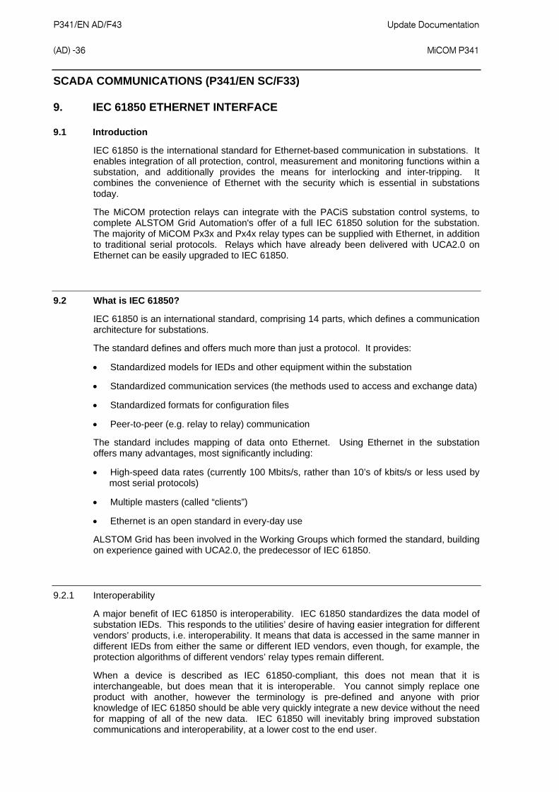
P341/EN AD/F43 Update Documentation (AD) -36
MiCOM P341
SCADA COMMUNICATIONS (P341/EN SC/F33)
9. IEC 61850 ETHERNET INTERFACE
9.1 Introduction
IEC 61850 is the international standard for Ethernet-based communication in substations. It enables integration of all protection, control, measurement and monitoring functions within a substation, and additionally provides the means for interlocking and inter-tripping. It combines the convenience of Ethernet with the security which is essential in substations today.
The MiCOM protection relays can integrate with the PACiS substation control systems, to complete ALSTOM Grid Automation's offer of a full IEC 61850 solution for the substation. The majority of MiCOM Px3x and Px4x relay types can be supplied with Ethernet, in addition to traditional serial protocols. Relays which have already been delivered with UCA2.0 on Ethernet can be easily upgraded to IEC 61850.
9.2 What is IEC 61850?
IEC 61850 is an international standard, comprising 14 parts, which defines a communication architecture for substations.
The standard defines and offers much more than just a protocol. It provides:
Standardized models for IEDs and other equipment within the substation
Standardized communication services (the methods used to access and exchange data)
Standardized formats for configuration files
Peer-to-peer (e.g. relay to relay) communication
The standard includes mapping of data onto Ethernet. Using Ethernet in the substation offers many advantages, most significantly including:
High-speed data rates (currently 100 Mbits/s, rather than 10’s of kbits/s or less used by most serial protocols)
Multiple masters (called “clients”)
Ethernet is an open standard in every-day use
ALSTOM Grid has been involved in the Working Groups which formed the standard, building on experience gained with UCA2.0, the predecessor of IEC 61850.
9.2.1 Interoperability
A major benefit of IEC 61850 is interoperability. IEC 61850 standardizes the data model of substation IEDs. This responds to the utilities’ desire of having easier integration for different vendors’ products, i.e. interoperability. It means that data is accessed in the same manner in different IEDs from either the same or different IED vendors, even though, for example, the protection algorithms of different vendors’ relay types remain different.
When a device is described as IEC 61850-compliant, this does not mean that it is interchangeable, but does mean that it is interoperable. You cannot simply replace one product with another, however the terminology is pre-defined and anyone with prior knowledge of IEC 61850 should be able very quickly integrate a new device without the need for mapping of all of the new data. IEC 61850 will inevitably bring improved substation communications and interoperability, at a lower cost to the end user.

Update Documentation P341/EN AD/F43 MiCOM P341
(AD) -37
9.2.2 The data model
To ease understanding, the data model of any IEC 61850 IED can be viewed as a hierarchy of information. The categories and naming of this information is standardized in the IEC 61850 specification.
Figure 8: Data model layers in IEC 61850

P341/EN AD/F43 Update Documentation (AD) -38
MiCOM P341
The levels of this hierarchy can be described as follows:
Physical Device – Identifies the actual IED within a system. Typically the device’s name or IP address can be used (for example Feeder_1 or 10.0.0.2).
Logical Device – Identifies groups of related Logical Nodes within the Physical Device. For the MiCOM relays, 5 Logical Devices exist: Control, Measurements, Protection, Records, System.
Wrapper/Logical Node Instance – Identifies the major functional areas within the IEC 61850 data model. Either 3 or 6 characters are used as a prefix to define the functional group (wrapper) while the actual functionality is identified by a 4 character Logical Node name suffixed by an instance number. For example, XCBR1 (circuit breaker), MMXU1 (measurements), FrqPTOF2 (overfrequency protection, stage 2).
Data Object – This next layer is used to identify the type of data you will be presented with. For example, Pos (position) of Logical Node type XCBR.
Data Attribute – This is the actual data (measurement value, status, description, etc.). For example, stVal (status value) indicating actual position of circuit breaker for Data Object type Pos of Logical Node type XCBR.
9.3 IEC 61850 in MiCOM relays
IEC 61850 is implemented in MiCOM relays by use of a separate Ethernet card. This card manages the majority of the IEC 61850 implementation and data transfer to avoid any impact on the performance of the protection.
In order to communicate with an IEC 61850 IED on Ethernet, it is necessary only to know its IP address. This can then be configured into either:
An IEC 61850 “client” (or master), for example a PACiS computer (MiCOM C264) or HMI, or
An “MMS browser”, with which the full data model can be retrieved from the IED, without any prior knowledge
9.3.1 Capability
The IEC 61850 interface provides the following capabilities:
Read access to measurements
All measurands are presented using the measurement Logical Nodes, in the ‘Measurements’ Logical Device. Reported measurement values are refreshed by the relay once per second, in line with the relay user interface.
Generation of unbuffered reports on change of status/measurement
Unbuffered reports, when enabled, report any change of state in statuses and/or measurements (according to deadband settings).

Update Documentation P341/EN AD/F43 MiCOM P341
(AD) -39
Support for time synchronization over an Ethernet link
Time synchronization is supported using SNTP (Simple Network Time Protocol); this protocol is used to synchronize the internal real time clock of the relays.
GOOSE peer-to-peer communication
GOOSE communications of statuses are included as part of the IEC 61850 implementation. Please see section Error! Reference source not found. for more details.
Disturbance record extraction
Extraction of disturbance records, by file transfer, is supported by the MiCOM relays. The record is extracted as an ASCII format COMTRADE file.
Setting changes (e.g. of protection settings) are not supported in the current IEC 61850 implementation. In order to keep this process as simple as possible, such setting changes are done using MiCOM S1 Settings & Records program. This can be done as previously using the front port serial connection of the relay, or now optionally over the Ethernet link if preferred (this is known as “tunneling”).
9.3.2 IEC 61850 configuration
One of the main objectives of IEC 61850 is to allow IEDs to be directly configured from a configuration file generated at system configuration time. At the system configuration level, the capabilities of the IED are determined from an IED capability description file (ICD) which is provided with the product. Using a collection of these ICD files from varying products, the entire protection of a substation can be designed, configured and tested (using simulation tools) before the product is even installed into the substation.
To aid in this process, the MiCOM S1 Support Software provides an IED Configurator tool which allows the pre-configured IEC 61850 configuration file (an SCD file or CID file) to be imported and transferred to the IED. Alongside this, the requirements of manual configuration are satisfied by allowing the manual creation of configuration files for MiCOM relays based on their original IED capability description (ICD file).
Other features include the extraction of configuration data for viewing and editing, and a sophisticated error checking sequence which ensures that the configuration data is valid for sending to the IED and that the IED will function within the context of the substation.
To aid the user, some configuration data is available in the ‘IED CONFIGURATOR’ column of the relay user interface, allowing read-only access to basic configuration data.
9.3.2.1 Configuration banks
To promote version management and minimize down-time during system upgrades and maintenance, the MiCOM relays have incorporated a mechanism consisting of multiple configuration banks. These configuration banks are categorized as:
Active Configuration Bank
Inactive Configuration Bank
Any new configuration sent to the relay is automatically stored into the inactive configuration bank, therefore not immediately affecting the current configuration. Both active and inactive configuration banks can be extracted at anytime.

P341/EN AD/F43 Update Documentation (AD) -40
MiCOM P341
When the upgrade or maintenance stage is complete, the IED Configurator tool can be used to transmit a command (to a single IED) authorizing the activation of the new configuration contained in the inactive configuration bank, by switching the active and inactive configuration banks. This technique ensures that the system down-time is minimized to the start-up time of the new configuration. The capability to switch the configuration banks is also available via the ‘IED CONFIGURATOR’ column.
For version management, data is available in the ‘IED CONFIGURATOR’ column in the relay user interface, displaying the SCL Name and Revision attributes of both configuration banks.
9.3.2.2 Network connectivity
Note: This section presumes a prior knowledge of IP addressing and related topics. Further details on this topic may be found on the Internet (search for IP Configuration) and in numerous relevant books.
Configuration of the relay IP parameters (IP Address, Subnet Mask, Gateway) and SNTP time synchronization parameters (SNTP Server 1, SNTP Server 2) is performed by the IED Configurator tool, so if these parameters are not available via an SCL file, they must be configured manually.
If the assigned IP address is duplicated elsewhere on the same network, the remote communications will operate in an indeterminate way. However, the relay will check for a conflict on every IP configuration change and at power up. An alarm will be raised if an IP conflict is detected.
The relay can be configured to accept data from networks other than the local network by using the ‘Gateway’ setting.
9.4 The data model of MiCOM relays
The data model naming adopted in the Px30 and Px40 relays has been standardized for consistency. Hence the Logical Nodes are allocated to one of the five Logical Devices, as appropriate, and the wrapper names used to instantiate Logical Nodes are consistent between Px30 and Px40 relays.
The data model is described in the Model Implementation Conformance Statement (MICS) document, which is available separately. The MICS document provides lists of Logical Device definitions, Logical Node definitions, Common Data Class and Attribute definitions, Enumeration definitions, and MMS data type conversions. It generally follows the format used in Parts 7-3 and 7-4 of the IEC 61850 standard.
9.5 The communication services of MiCOM relays
The IEC 61850 communication services which are implemented in the Px30 and Px40 relays are described in the Protocol Implementation Conformance Statement (PICS) document, which is available separately. The PICS document provides the Abstract Communication Service Interface (ACSI) conformance statements as defined in Annex A of Part 7-2 of the IEC 61850 standard.

Update Documentation P341/EN AD/F43 MiCOM P341
(AD) -41
9.6 Peer-to-peer (GSE) communications
The implementation of IEC 61850 Generic Substation Event (GSE) sets the way for cheaper and faster inter-relay communications. The generic substation event model provides the possibility for a fast and reliable system-wide distribution of input and output data values. The generic substation event model is based on the concept of an autonomous decentralization, providing an efficient method allowing the simultaneous delivery of the same generic substation event information to more than one physical device through the use of multicast services.
The use of multicast messaging means that IEC 61850 GOOSE uses a publisher-subscriber system to transfer information around the network*. When a device detects a change in one of its monitored status points it publishes (i.e. sends) a new message. Any device that is interested in the information subscribes (i.e. listens) to the data it contains.
Note: * Multicast messages cannot be routed across networks without specialized equipment.
Each new message is re-transmitted at user-configurable intervals until the maximum interval is reached, in order to overcome possible corruption due to interference, and collisions. In practice, the parameters which control the message transmission cannot be calculated. Time must be allocated to the testing of GSE schemes before or during commissioning, in just the same way a hardwired scheme must be tested.
9.6.1 Scope
A maximum of 32 virtual inputs are available within the PSL which can be mapped directly to a published dataset in a GOOSE message (only 1 fixed dataset is supported). All published GOOSE signals are BOOLEAN values.
Each GOOSE signal contained in a subscribed GOOSE message can be mapped to any of the 32 virtual inputs within the PSL. The virtual inputs allow the mapping to internal logic functions for protection control, directly to output contacts or LEDs for monitoring.
The MiCOM relay can subscribe to all GOOSE messages but only the following data types can be decoded and mapped to a virtual input:
BOOLEAN
BSTR2
INT16
INT32
INT8
UINT16
UINT32
UINT8

P341/EN AD/F43 Update Documentation (AD) -42
MiCOM P341
9.6.2 IEC 61850 GOOSE configuration
All GOOSE configuration is performed via the IED Configurator tool available within the MiCOM S1 Support Software.
All GOOSE publishing configuration can be found under the ‘GOOSE Publishing’ tab in the configuration editor window. All GOOSE subscription configuration can be found under the ‘External Binding’ tab in the configuration editor window. Care should be taken to ensure that the configuration is correct, to ensure efficient GOOSE scheme operation.
Settings to enable GOOSE signaling and to apply Test Mode are available via the relay user interface.
9.7 Ethernet functionality
Settings relating to a failed Ethernet link are available in the ‘COMMUNICATIONS’ column of the relay user interface.
9.7.1 Ethernet disconnection
IEC 61850 ‘Associations’ are unique and made to the relay between the client (master) and server (IEC 61850 device). In the event that the Ethernet is disconnected, such associations are lost, and will need to be re-established by the client. The TCP_KEEPALIVE function is implemented in the relay to monitor each association, and terminate any which are no longer active.
9.7.2 Loss of power
The relay allows the re-establishment of associations by the client without a negative impact on the relay’s operation after having its power removed. As the relay acts as a server in this process, the client must request the association. Uncommitted settings are cancelled when power is lost, and reports requested by connected clients are reset and must be re-enabled by the client when it next creates the new association to the relay.
INSTALLATION (P341/EN IN/F33)
6.9. Ethernet port for IEC 61850 (if applicable)
Fiber Optic Port
The relays can have 100 Mbps Ethernet port. FO connection is recommended for use in permanent connections in a substation environment. The 100Mbit port uses type ST connector, compatible with fiber multimode 50/125µm or 62.5/125µm - 13000nm.
RJ-45 Metallic Port
The user can connect to either a 10Base-T or a 100Base-TX Ethernet hub; the port will automatically sense which type of hub is connected. Due to possibility of noise and interference on this part, it is recommended that this connection type be used for short-term connections and over short distance. Ideally where the relays and hubs are located in the same cubicle.
The connector for the Ethernet port is a shielded RJ-45. The table shows the signals and pins on the connector.

Update Documentation P341/EN AD/F43 MiCOM P341
(AD) -43
Pin Signal Name Signal Definition
1 TXP Transmit (positive)
2 TXN Transmit (negative)
3 RXP Receive (positive)
4 - Not used
5 - Not used
6 RXN Receive (negative)
7 - Not used
8 - Not used
Table 4: Signals on the Ethernet connector
RELAY DESCRIPTION (P341/EN HW/F33)
1.1.6. Ethernet board
This is a mandatory board for IEC 61850 enabled relays. It provides network connectivity through either copper or fiber media at rates of 10Mb/s (copper only) or 100Mb/s. There is also an option on this board to specify IRIG-B port (modulated or un-modulated). This board, the IRIG-B board and second rear comms board are mutually exclusive as they all utilize slot A within the relay case.
All modules are connected by a parallel data and address bus which allows the processor board to send and receive information to and from the other modules as required.
There is also a separate serial data bus for conveying sample data from the input module to the processor. Figure 1 shows the modules of the relay and the flow of information between them.

P341/EN AD/F43 Update Documentation (AD) -44
MiCOM P341
�������������1����
2 ���1����
��3������ ��1���� �����������1����
�����
1����
���� ������1��
4 �����2��
���
����2��� ��4��������������
���� ����������
�������5�!� ��"�������
6�"��� ����
���
��3����� �
2�������2��#$%����������������
�����
��� �����
����
�6�
�������� ���
����7��� ���
��������� �"����������"�� �
��3������ ��� �!� ��"��8�������������
6�"��� �������!� ��
��3������ �8���������
����8��������� ���������
�����"�����
9�����"������
4� �!� ��"
�������
6��� �������"��5���������8
��"��"��&�8�����3�����'
������!� ������� ������"�'
4�����:�6����
:�6�
� ���8�!��8���� �8������1���5������������������������
;�����1�<�7���2��
�&���1 �����3��
���5�����8������"
����1�������
�2��
�����������
����������������������2��#$%
�������
4�1��������������������
������� �2�=7;����>����������������1����
�����������
�2�=7;����>���4����������8����2�=7;���"��
�������
�������1���������������
������������� ���������������
������
�������������
����
���
����
����������������������������
���
����
���
���
����
����
���
�
Figure 1: Relay modules and information flow
2.4.3 High break relay board
One ‘high break’ output relay board consisting of four normally open output contacts is available for the P341 as an option.
This board contains a hybrid of MOSFET solid state devices (SSD) in parallel with high capacity relay output contacts. The MOSFET has a varistor across it to provide protection which is required when switching off inductive loads as the stored energy in the inductor causes a reverse high voltage which could damage the MOSFET.

Update Documentation P341/EN AD/F43 MiCOM P341
(AD) -45
When there is a control input command to operate an output contact the miniature relay is operated at the same time as the SSD. The miniature relay contact closes in nominally 3.5 mS and is used to carry the continuous load current; the SSD operates in <0.2ms and is switched off after 7.5mS. When the control input resets to open the contacts, the SSD is again turned on for 7.5mS. The miniature relay resets in nominally 3.5ms before the SSD and so the SSD is used to break the load. The SSD absorbs the energy when breaking inductive loads and so limits the resulting voltage surge. This contact arrangement is for switching dc circuits only. As the SSD comes on very fast (<0.2ms) then these high break output contacts have the added advantage of being very fast operating.
3.5ms + contact bounce
load current
relay contact
databuscontrol input
MOSFET reset
MOSFET operateon
7ms
on
3.5ms
closed
on7ms
off
P1981ENa
Figure 3: High break contact operation
2.4.3.1 High break contact applications
1) Efficient scheme engineering
In traditional hardwired scheme designs, high break capability could only be achieved using external electromechanical trip relays. External MVAJ tripping relays can be used or the new high break contacts inside MiCOM relays can be used – reducing panel space.
2) Accessibility of CB auxiliary contacts
Common practice is to use circuit breaker 52a (CB Closed) auxiliary contacts to break the trip coil current on breaker opening, thus easing the duty on the protection contacts. In cases such as operation of disconnectors, or retrofitting, it may be that 52a contacts are either unavailable or unreliable. High break contacts can be used to break the trip coil current in these applications.

P341/EN AD/F43 Update Documentation (AD) -46
MiCOM P341
3) Breaker fail
The technique to use 52a contacts in trip circuits was described above. However, in the event of failure of the local circuit breaker (stuck breaker), or defective auxiliary contacts (stuck contacts), the 52a contact action is incorrect. The interrupting duty at the local breaker then falls on the relay output contacts which may not be rated to perform this duty. MiCOM high break contacts will avoid the risk of burnt relay contacts.
4) Initiation of teleprotection
The MiCOM high break contacts also offer fast making. This can provide faster tripping: additionally, fast keying of teleprotection is a benefit. Fast keying bypasses the usual contact operation time, such that permissive, blocking and intertrip commands can be routed faster.
2.9 Ethernet board
The optional Ethernet board (ZN0049) has 3 variants which support the IEC 61850 implementation:
100 Mbits/s Fiber Optic + 10/100 Mbits/s Copper
100 Mbits/s Fiber Optic + 10/100 Mbits/s Copper + modulated IRIG-B
100 Mbits/s Fiber Optic + 10/100 Mbits/s Copper + un-modulated IRIG-B
This card is fitted into Slot A of the relay, which is the optional communications slot. Each Ethernet card has a unique MAC address used for Ethernet communications. This is printed on the rear of the card, alongside the Ethernet sockets.
The 100 Mbits/s Fiber Optic ports use ST® type connectors and are suitable for 1300nm multi-mode fiber type.
Copper ports use RJ45 type connectors. When using copper Ethernet, it is important to use Shielded Twisted Pair (STP) or Foil Twisted Pair (FTP) cables, to shield the IEC 61850 communications against electromagnetic interference. The RJ45 connector at each end of the cable must be shielded, and the cable shield must be connected to this RJ45 connector shield, so that the shield is grounded to the relay case. Both the cable and the RJ45 connector at each end of the cable must be Category 5 minimum, as specified by the IEC 61850 standard. It is recommended that each copper Ethernet cable is limited to a maximum length of 3 meters and confined within one bay/cubicle.
When using IEC 61850 communications through the Ethernet card, the rear EIA(RS)485 and front EIA(RS)232 ports are also available for simultaneous use, both using the Courier protocol.
The physical layout of the Ethernet board is shown in Figure 5.
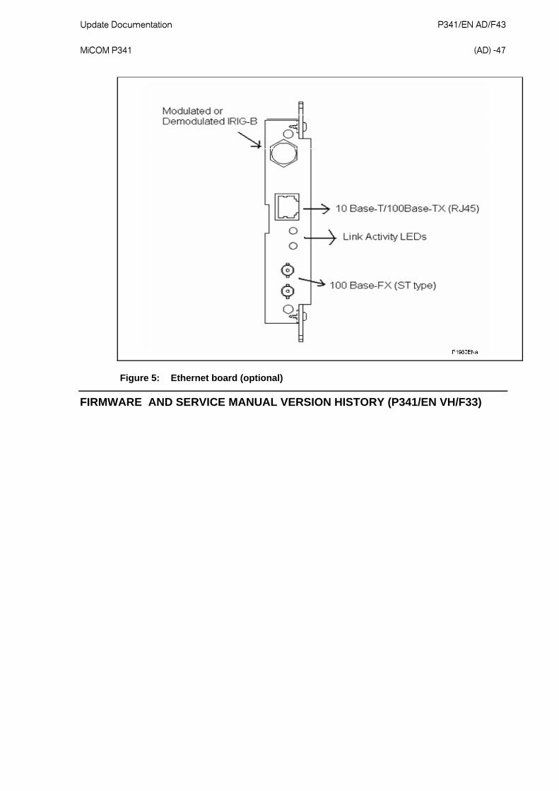
Update Documentation P341/EN AD/F43 MiCOM P341
(AD) -47
Figure 5: Ethernet board (optional)
FIRMWARE AND SERVICE MANUAL VERSION HISTORY (P341/EN VH/F33)

Update D
ocumentation
P
341/EN
AD
/F43
M
iCO
M P
341
(AD
) -48
Relay type: P341 …
Software Version
Major Minor
Hardware Suffix
Original Date of Issue
Description of Changes S1
Compatibility Technical
Documentation
A A Oct 1999 Original Issue V1.09 or Later TG8617A
B A Dec 1999
Corrected 90 degree phase angle displacement in measurement of Ia, Ib, Ic
Corrected VT scaling factors for Va, Vb, Vc in fault records
Minor bug fixes
V1.09 or Later TG8617A
01
C A Mar 2000
Trip LED status saved during power cycling
Corrections to omission of fault duration and CB operating time in fault record
Corrected -90 degree phase angle displacement in measurement of VN and VN derived
Reset of alarms and indications event added to event record
Minor bug fixes
V1.09 or Later TG8617A
02 A A Oct 2000
DNP 3.0 protocol added
Courier and MODBUS enhancements to improve compatibility with other protection (mainly PX20 products)
Modifications to IEC60870-5-103 Test Mode
Poledead logic DDB signals made visible in PSL
Foreign Language text updated
Active and reactive power added to MODBUS fault record
Minor bug fixes
V1.10 or Later P341/EN T/B11

Update D
ocumentation
P
341/EN
AD
/F43
M
iCO
M P
341
(AD
) -49
Relay type: P341 …
Software Version
Major Minor
Hardware Suffix
Original Date of Issue
ription of Changes S1
Compatibility Technical
Documentation Desc
A A Jan 2001
Event filtering added
Correction to energy measurement inaccuracy
Minor bug fixes
V2.00 or Later P341/EN T/B11
B A May 2001 Minor bug fixes V2.00 or Later P341/EN T/B11
C A Jan 2002 Resolved possible reboot caused by Disturbance Recorder
Minor bug fixes V2.00 or Later P341/EN T/B11
D A Feb 2002
Resolved possible reboot caused by invalid MODBUS requests
Minor bug fixes
V2.00 or Later P341/EN T/B11 03
E A Dec 2002
DNP 3.0 Object 12 “CROB” implementation is now compliant for simple function points
DNP 3.0 Object 10 included in Class 0 poll
DNP 3.0 support for season in time information
Correction to MODBUS CB Trip and Close via "0" command
Change to neutral voltage displacement protection and directional SEF protection so that they are not blocked by the VT supervision logic when the VN Input and ISEF>VNPol are selected as Measured
V2.00 or Later P341/EN T/B11

Update D
ocumentation
P
341/EN
AD
/F43
M
iCO
M P
341
(AD
) -50
Relay type: P341 …
Software Version
Major Minor
Hardware Suffix
Original Date of Issue
S1 Compatibility
Technical Documentation
Description of Changes
03 Cont.
E A Dec 2002
Correction to undervoltage stage 2 (V<2) setting range. The setting range has been increased from 10-70V to 10-120V (Vn=110/120V) so that it is the same as V<1
Correction to VT ratio scaling problem in the disturbance recorder
Correction to value of derived neutral current shown on the front panel default display.
Minor bug fixes
V2.00 or Later P341/EN T/B11

Update D
ocumentation
P
341/EN
AD
/F43
M
iCO
M P
341
(AD
) -51
Relay type: P341 …
Software Version
Major Minor
Hardware Suffix
Original Date of Issue
S1 Compatibility
Technical Documentation
Description of Changes
03 Cont.
F A March 2004
Correction to the fault recorder window for current based trips so that it can terminate properly once the FAULT_REC_TRIG signal (DDB 288) is reset. Previously it needed to wait for Relay 3 to reset also before termination.
Power measurement limits added to prevent non zero values with no current and voltage. Also power factor measurements limited to +/-1.
Resolved possible reboot caused by failure to time sync from DNP 3.0 when IRIG-B is active which is also providing the time sync. Now, any failure of the DNP 3.0 to time sync will only produce a maintenance record.
Resolved possible problem with disturbance recorder triggering which could cause loss of disturbance record data, temporary freezing of the user interface or loss of rear port communications
Resolved unreliable MODBU framing
Resolved creation of spurious password expired event when menu cell or MODBUS register is accessed.
Resolved error code 0x 8D840000
Resolved incorrect derived ‘IN’ value on front panel default display
Minor bug fixes
V2.00 or Later P341/EN T/B11
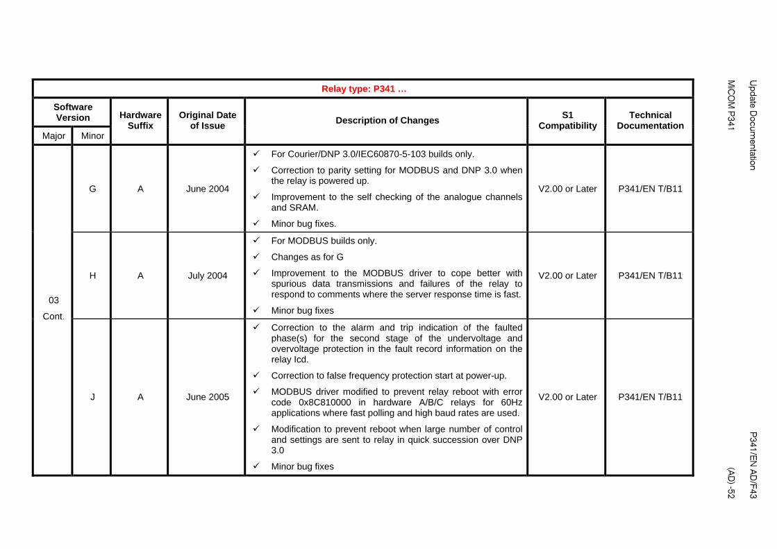
Update D
ocumentation
P
341/EN
AD
/F43
M
iCO
M P
341
(AD
) -52
Relay type: P341 …
Software Version
Major Minor
Hardware Suffix
Original Date of Issue
S1 Compatibility
Technical Documentation
Description of Changes
G A June 2004
For Courier/DNP 3.0/IEC60870-5-103 builds only.
Correction to parity setting for MODBUS and DNP 3.0 when the relay is powered up.
Improvement to the self checking of the analogue channels and SRAM.
Minor bug fixes.
V2.00 or Later P341/EN T/B11
H A July 2004
For MODBUS builds only.
Changes as for G
Improvement to the MODBUS driver to cope better with spurious data transmissions and failures of the relay to respond to comments where the server response time is fast.
Minor bug fixes
V2.00 or Later P341/EN T/B11
03
Cont.
J A June 2005
Correction to the alarm and trip indication of the faulted phase(s) for the second stage of the undervoltage and overvoltage protection in the fault record information on the relay Icd.
Correction to false frequency protection start at power-up.
MODBUS driver modified to prevent relay reboot with error code 0x8C810000 in hardware A/B/C relays for 60Hz applications where fast polling and high baud rates are used.
Modification to prevent reboot when large number of control and settings are sent to relay in quick succession over DNP 3.0
Minor bug fixes
V2.00 or Later P341/EN T/B11

Update D
ocumentation
P
341/EN
AD
/F43
M
iCO
M P
341
(AD
) -53
Relay type: P341 …
Software Version
Major Minor
Hardware Suffix
Original Date of Issue
Changes S1
Compatibility Technical
Documentation Description of
A A June 2001
Not released to production
Sensitive reverse power added
Neutral voltage displacement threshold, VN>1/2, increased from 50 to 80V (Vn=100/120V), 200 to 320 V (Vn=380/480V)
Earth fault polarizing voltage threshold, Vnpol, increased from 22 to 88V (Vn=100/120V) and 88 to 352V (Vn=380/480V)
cos phi and sin phi features added to SEF protection
Minor bug fixes
V2.01 or Later P341/EN T/B11
B A July 2001
Not released to production
Minor bug fix to background self check diagnostics introduced in 04A
V2.01 or Later P341/EN T/B11
C A Dec 2001 Minor bug fixes V2.01 or Later P341/EN T/B11
D A Jan 2002 Resolved possible reboot caused by Disturbance Recorder
Minor bug fixes V2.01 or Later P341/EN T/B11
E A Feb 2002
Resolved possible reboot caused by invalid MODBUS requests
Minor bug fixes
V2.01 or Later P341/EN T/B11
04
F A Dec 2002
Enhanced DNP 3.0 Object 10 support for Pulse On/Close control points
DNP 3.0 Object 10 included in Class 0 poll
DNP 3.0 support for season in time information
V2.01 or Later P341/EN T/B11

Update D
ocumentation
P
341/EN
AD
/F43
M
iCO
M P
341
(AD
) -54
Relay type: P341 …
Software Version
Major Minor
Hardware Suffix
Original Date of Issue
S1 Compatibility
Technical Documentation
Description of Changes
04
Cont. F A Dec 2002
Correction to MODBUS CB Trip and Close via "0" command
Change to neutral voltage displacement protection and directional SEF protection so that they are not blocked by the VT supervision logic when the VN Input and ISEF>VNPol are selected as Measured
Correction to undervoltage stage 2 (V<2) setting range. The setting range has been increased from 10-70V to 10-120V (Vn=110/120V) Correction to VT ratio scaling problem in the disturbance recorder
Minor bug fixes
V2.01 or Later P341/EN T/B11

Update D
ocumentation
P
341/EN
AD
/F43
M
iCO
M P
341
(AD
) -55
Relay type: P341 …
Software Version
Major Minor
Hardware Suffix
Original Date of Issue
S1 Compatibility
Technical Documentation
Description of Changes
G A March 2004
Correction to the fault recorder window for current based trips so that it can terminate properly once the FAULT_REC_TRIG signal (DDB 288) is reset. Previously it needed to wait for Relay 3 to reset also before termination
Power measurement limits added to prevent non zero values with no current voltage. Also power factor measurements
Resolved possible reboot caused by failure to time sync from DNP 3.0 when IRIG-B is active which is also providing the time sync. Now any failure of the DNP 3.0 to time sync will only produce a maintenance record
Resolved possible problem with disturbance recorder triggering which could cause loss of disturbance record data, temporary freezing of the user interface or loss of rear port
Resolved unreliable MODBUS framing
Resolved creation of spurious password expired event when menu cell or MODBUS register is accessed
Resolved error code 0x 8D840000
Resolved incorrect derived ‘IN’ value on front panel default display
Minor bug fixes
V2.01 or Later P341/EN T/B11
04
Cont.
H A June 2004
For Courier/DNP 3.0/IEC60870-5-103 builds only
Correction to parity setting for MODBUS and DNP 3.0 when the relay is powered up
Improvement to the self checking of the analogue channels and SRAM
Minor bug fixes
V2.01 or Later P341/EN T/B11

Update D
ocumentation
P
341/EN
AD
/F43
M
iCO
M P
341
(AD
) -56
Relay type: P341 …
Software Version
Major Minor
Hardware Suffix
Original Date of Issue
Changes S1
Compatibility Technical
Documentation Description of
J A July 2004
For MODBUS builds only
Changes as for H
Improvement to the MODBUS driver to cope better with spurious data transmissions and failures of the relay to respond to commands where the server response time is fast
Minor bug fixes
V2.01 or Later P341/EN T/B11 04
Cont.
K A June 2004 Changes are the same as 03J V2.01 or Later P341/EN T/B11
05 A A/B Sept 2001
Not released to production
Thermal overload protection added
Control inputs added
PSL DDB list of signals increased from 512 to 1023 signals
PSL Data menu added with PSL Reference information for version history
Optional additional opto inputs and output contacts
New ‘Universal’ wide ranging opto inputs (Model number hardware suffix changed to B)
New output contacts with better break and continuous carry ratings (Model number hardware suffix changed to B)
Minor bug fixes
Courier and MODBUS builds only
V2.05 or Later P341/EN T/D22

Update D
ocumentation
P
341/EN
AD
/F43
M
iCO
M P
341
(AD
) -57
Relay type: P341 …
Software Version
Major Minor
Hardware Suffix
Original Date of Issue
Changes S1
Compatibility Technical
Documentation Description of
B A/B Oct 2001
Not released to production
Correction to VT ratio scaling problem in the disturbance recorder
Minor bug fixes
Courier and MODBUS builds only
V2.05 or Later P341/EN T/D22
D A/B Feb 2002
Resolved possible reboot caused by Disturbance Recorder
Resolved possible reboot caused by invalid MODBUS requests
Enhancements to IEC60870-5-103 build to include private codes, monitor blocking and disturbance record extraction. New uncompressed disturbance recorder for IEC60870-5-103 build only
Correction to IEC60870-5-103 voltage measurements for Vn=380/480V relays
Minor bug fixes
V2.05 or Later P341/EN T/D22
05
Cont.
E A/B Mar 2002 Minor bug fixes V2.05 or Later P341/EN T/D22

Update D
ocumentation
P
341/EN
AD
/F43
M
iCO
M P
341
(AD
) -58
Relay type: P341 …
Software Version
Major Minor
Hardware Suffix
Original Date of Issue
S1 Compatibility
Technical Documentation
Description of Changes
05
Cont. F A/B Oct 2002
DNP 3.0 Object 12 “CROB” implementation is now compliant for simple function points
Correction to MODBUS CB Trip and Close via "0" command
Change to neutral voltage displacement protection and directional SEF protection so that they are not blocked by the VT supervision logic when the VN Input and ISEF>VNPol are selected as Measured
Correction to undervoltage stage 2 (V<2) setting range. The setting range has been increased from 10-70V to 10-120V (Vn=110/120V) so that it is the same as V<1
Minor bug fixes
V2.05 or Later P341/EN T/D22

Update D
ocumentation
P
341/EN
AD
/F43
M
iCO
M P
341
(AD
) -59
Relay type: P341 …
Software Version
Major Minor
Hardware Suffix
Original Date of Issue
S1 Compatibility
Technical Documentation
Description of Changes
05
Cont. G A/B August 2000
Control input sales added to non volatile memory
German language text updated
Power measurement limits added to prevent non zero values with no current and voltage. Also power factor measurements limited to +/-1
In the Commissioning Test menu the DDB status has been made visible on the front panel display
Support for the Trip LED Status and Alarm Status added to G26 data type for MODBUS register 30001
Correction to the CB trip/Close functionality via MODBUS so that local/remote setting in the CB control menu is not ignored
Correction to MODBUS auto event extraction which does not work correctly
DNP 3.0 Object 12 “CROB” implementation is now compliant for simple function points
DNP 3.0 object 10 added to class 0 poll
Correction to DNP 3.0 time sync operation so that it does not modify the season bit in the time stamp
Correction to the manual reset user alarms so that the event record shows the alarm turning off when a reset command has been issued. Previously the “alarm off” event is produced once the initiating signal is removed.
Correction to the fault recorder window for current based trips so that it can terminate properly once the FAULT_REC_TRIG signal (DDB 288) is reset. Previously it needed to wait for Relay 3 to reset also before termination
V2.05 or Later P341/EN T/D22

Update D
ocumentation
P
341/EN
AD
/F43
M
iCO
M P
341
(AD
) -60
Relay type: P341 …
Software Version
Major Minor
Hardware Suffix
Original Date of Issue
S1 Compatibility
Technical Documentation
Description of Changes
05.
Cont. G A/B August 2000
Resolved possible reboot caused by failure to time sync from DNP 3.0 when IRIG-B is active which is also providing the time sync. Now, any failure of the DNP 3.0 to time sync will only produce a maintenance record.
Correction to the alarm and trip indication of the faulted phase(s) for the second stage of the undervoltage and overvoltage protection in the fault record information on the relay Icd
Correction to the C32CS error when extracting and saving an uncompressed disturbance record from the P341 through the front port using MiCOM S1. This only applies to P341 IEC60870-5-103 protocol builds since this is the only communication option which supports uncompressed disturbance records. The error is caused by unavailable opto inputs or relay contacts being assigned to digital inputs in the Disturbance Recorder menu.
Resolved possible problem with disturbance recorder triggering which could cause loss of disturbance record data, temporary freezing of the user interface or loss of rear port communications
Resolved unreliable MODBUS framing
Resolved creation of spurious password expired event when menu cell or MODBUS register is accessed.
Resolved error code 0x 8D840000
Resolved incorrect derived ‘IN’ value on front panel default display
Minor bug fixes
V2.05 or Later P341/EN T/D22

Update D
ocumentation
P
341/EN
AD
/F43
M
iCO
M P
341
(AD
) -61
Relay type: P341 …
Software Version
Major Minor
Hardware Suffix
Original Date of Issue
S1 Compatibility
Technical Documentation
Description of Changes
H A/B June 2004
For Courier/DNP 3.0/IEC60870-5-103 builds only
Correction to parity setting for MODBUS and DNP 3.0 when the relay is powered up
Improvement to the self checking of the analogue channels and SRAM
Minor bug fixes
V2.05 or Later P341/EN T/D22
05
Cont.
J A/B June 2004
For MODBUS builds only
Changes as for H
Improvement to the MODBUS driver to cope better with spurious data transmissions and failures of the relay to respond to commands where the server response time is fast
Minor bug fixes
V2.05 or Later P341/EN T/D22

Update D
ocumentation
P
341/EN
AD
/F43
M
iCO
M P
341
(AD
) -62
Relay type: P341 …
Software Version
Major Minor
Hardware Suffix
Original Date of Issue
S1 Compatibility
Technical Documentation
Description of Changes
05
Cont. K A/B June 2004
MODBUS Time Transmission Format selectable via MODBUS only setting as Standard or Reverse for transmission of byte order
DO/PU ratio changed from 95% to 98% for Over/Under Voltage protection. Trip threshold changed from 1.05, 0.95 Vs to 1 Vs for Over and Under Voltage and NVD protection. TMS setting of Under/Over Voltage protection reduced from 0.5 to 0.05.
Correction to false frequency protection start at power-up. MODBUS driver modified to prevent relay reboot with error code 0x8C810000 in hardware A/B/C relays for 60Hz applications where fast polling and high baud rates are used.
Modification to prevent reboot when large number of control and settings are sent to relay in quick succession over DNP 3.0
IEC60870-5-103. Status of summer bit now works correctly in time sync command.
Correction to DNP 3.0 software where settings download from MiCOM S1 can fail for relays that have model dependent I/O configurations.
Minor bug fixes
V2.05 or Later P341/EN T/D22

Update D
ocumentation
P
341/EN
AD
/F43
M
iCO
M P
341
(AD
) -63
Relay type: P341 …
Software Version
Major Minor
Hardware Suffix
Original Date of Issue
Changes S1
Compatibility Technical
Documentation Description of
06 A A/C Aug 2000
Not released to production
Additional IDMT characteristics for overcurrent protection (rectifier and RI curve), earth fault protection (RI and IDG curve) and sensitive earth fault protection (IDG curve)
Change to time dial setting range of IEEE and US curves. Previously curves were based on TD/7 where TD = 0.5-15. Now, curves are based on TD where TD = 0.01-100. Also, includes change to US ST Inverse (C02) curve. K constant and L constant multiplied x 7 because of change to TD, now K=0.16758 and L=0.11858
Angle measurements for sequence quantities in Measurements 1 menu added
Optional 2nd rear communication port added
New power supply with increased output rating and reduced dc inrush current (typically < 10A). (Model number hardware changed to suffix C)
Wider setting range for Power and Sensitive Power protection. P>1/2 (reverse power) and P<1/2 (low forward power) maximum setting changed from 40In to 300In W (Vn=100/120V) and from 160In W to 1200In W (Vn=380/480V). Sen –P>1/2 and Sen P<1/2 maximum setting changed from 15In to 100In W (Vn=100/120V) and from 60In to 400In W (Vn=380/480V). There is also an additional setting for the Power and Sensitive Power protection to select the Operating mode as Generating or Motoring
V2.06 or Later P341/EN M/E33

Update D
ocumentation
P
341/EN
AD
/F43
M
iCO
M P
341
(AD
) -64
Relay type: P341 …
Software Version
Major Minor
Hardware Suffix
Original Date of Issue
S1 Compatibility
Technical Documentation
Description of Changes
A A/C Aug 2000
Maximum overfrequency protection setting increased from 65 to 68 Hz
Change to undervoltage stage 2 (V<2) setting range to correct an error. The setting range has been increased from 10-70 V to 10-120V (Vn=100/120V) so that it is the same as V<1
Change to neutral voltage displacement protection and directional SEF protection so that they are now not blocked by the voltage transformer supervision logic when the VN Input and ISEF> VN Pol are selected as Measured
Includes all the improvements and corrections in 05F software except for 2 enhancement shown for 06B
Minor bug fixes
V2.06 or Later P341/EN M/E33
B A/C Oct 2002
Correction to undervoltage stage 2 (V<2) setting range. The setting range has been increased from 10-70V to 10-120V (Vn=110/120V) so that it is the same as V<1
Enhancements to IEC608750-5-103 build to include private codes, monitor blocking and disturbance record extraction. New uncompressed disturbance recorder for IEC60870-5-103 build
Minor bug fixes
V2.06 or Later P341/EN M/E33
06 Cont.
C A/C March 2004 Changes are the same as 05G V2.06 or Later P341/EN M/E33
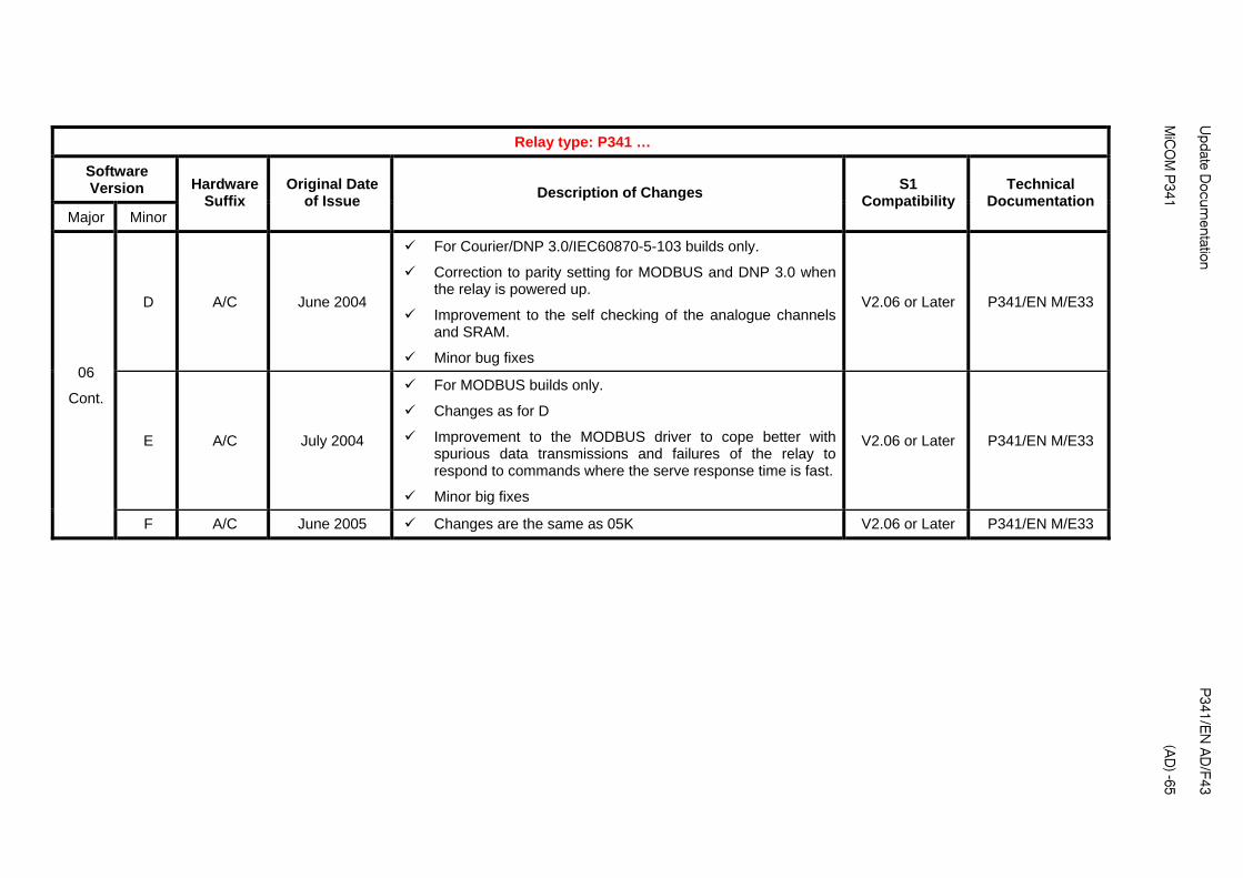
Update D
ocumentation
P
341/EN
AD
/F43
M
iCO
M P
341
(AD
) -65
Relay type: P341 …
Software Version
Major Minor
Hardware Suffix
Original Date of Issue
S1 Compatibility
Technical Documentation
Description of Changes
D A/C June 2004
For Courier/DNP 3.0/IEC60870-5-103 builds only.
Correction to parity setting for MODBUS and DNP 3.0 when the relay is powered up.
Improvement to the self checking of the analogue channels and SRAM.
Minor bug fixes
V2.06 or Later P341/EN M/E33
E A/C July 2004
For MODBUS builds only.
Changes as for D
Improvement to the MODBUS driver to cope better with spurious data transmissions and failures of the relay to respond to commands where the serve response time is fast.
Minor big fixes
V2.06 or Later P341/EN M/E33
06
Cont.
F A/C June 2005 Changes are the same as 05K V2.06 or Later P341/EN M/E33
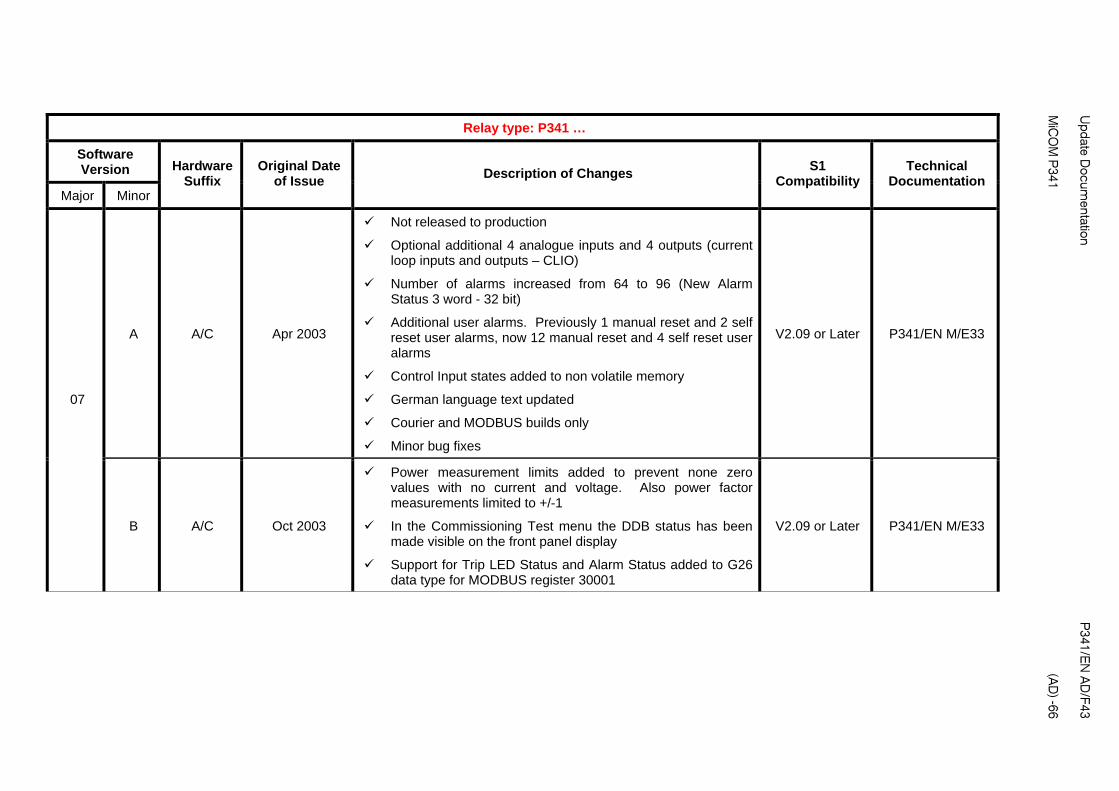
Update D
ocumentation
P
341/EN
AD
/F43
M
iCO
M P
341
(AD
) -66
Relay type: P341 …
Software Version
Major Minor
Hardware Suffix
Original Date of Issue
Changes S1
Compatibility Technical
Documentation Description of
A A/C Apr 2003
Not released to production
Optional additional 4 analogue inputs and 4 outputs (current loop inputs and outputs – CLIO)
Number of alarms increased from 64 to 96 (New Alarm Status 3 word - 32 bit)
Additional user alarms. Previously 1 manual reset and 2 self reset user alarms, now 12 manual reset and 4 self reset user alarms
Control Input states added to non volatile memory
German language text updated
Courier and MODBUS builds only
Minor bug fixes
V2.09 or Later P341/EN M/E33
07
B A/C Oct 2003
Power measurement limits added to prevent none zero values with no current and voltage. Also power factor measurements limited to +/-1
In the Commissioning Test menu the DDB status has been made visible on the front panel display
Support for Trip LED Status and Alarm Status added to G26 data type for MODBUS register 30001
V2.09 or Later P341/EN M/E33
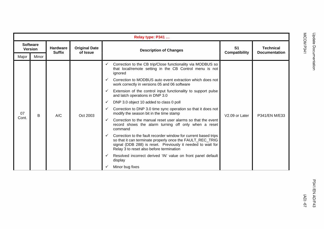
Update D
ocumentation
P
341/EN
AD
/F43
M
iCO
M P
341
(AD
) -67
Relay type: P341 …
Software Version
Major Minor
Hardware Suffix
Original Date of Issue
S1 Compatibility
Technical Documentation
Description of Changes
07 Cont.
B A/C Oct 2003
Correction to the CB trip/Close functionality via MODBUS so that local/remote setting in the CB Control menu is not ignored
Correction to MODBUS auto event extraction which does not work correctly in versions 05 and 06 software
Extension of the control input functionality to support pulse and latch operations in DNP 3.0
DNP 3.0 object 10 added to class 0 poll
Correction to DNP 3.0 time sync operation so that it does not modify the season bit in the time stamp
Correction to the manual reset user alarms so that the event record shows the alarm turning off only when a reset command
Correction to the fault recorder window for current based trips so that it can terminate properly once the FAULT_REC_TRIG signal (DDB 288) is reset. Previously it needed to wait for Relay 3 to reset also before termination
Resolved incorrect derived ‘IN’ value on front panel default display
Minor bug fixes
V2.09 or Later P341/EN M/E33

Update D
ocumentation
P
341/EN
AD
/F43
M
iCO
M P
341
(AD
) -68
Relay type: P341 …
Software Version
Major Minor
Hardware Suffix
Original Date of Issue
S1 Compatibility
Technical Documentation
Description of Changes
07
Cont. C A/C March 2004
Resolved possible reboot caused by failure to time sync from DNP 3.0 when IRIG-B is active which is also providing the time sync. Now, any failure of the DNP 3.0 to time sync will only produce a maintenance record.
Correction to the alarm and trip indication of the faulted phase(s) for the second stage of the undervoltage and overvoltage protection in the fault record information on the relay Icd.
Correction to the C32CS error when extracting and saving an uncompressed disturbance record from the P34x through the front port using MiCOM S1. This only applies to P34xIEC60870-5-103 protocol builds since this is the only communication option which supports uncompressed disturbance records. The error is caused by unavailable opto inputs or relay contacts being assigned to digital inputs in the Disturbance Recorder menu.
Resolved possible problem with disturbance recorder triggering which could cause loss of disturbance record data, temporary freezing of the user interface or loss of rear port communications
Resolved unreliable MODBUS framing
Resolved error code 0x 8D840000
Minor bug fixes
V2.09 or Later P341/EN M/E33

Update D
ocumentation
P
341/EN
AD
/F43
M
iCO
M P
341
(AD
) -69
Relay type: P341 …
Software Version
Major Minor
Hardware Suffix
Original Date of Issue
S1 Compatibility
Technical Documentation
Description of Changes
D A/C June 2004
For Courier/DNP 3.0/IEC60870-5-103 builds only
Correction to parity setting for MODBUS and DNP 3.0 when the relay is powered up
Improvement to the self checking of the analogue channels and SRAM
Minor bug fixes
V2.09 or Later P341/EN M/E33
E A/C July 2004
For MODBUS builds only.
Changes as for D
Improvement to the MODBUS driver to cope better with spurious data transmissions and failures of the relay to respond to commands where the server response time is fast.
Minor bug fixes
V2.09 or Later P341/EN M/E33
07
Cont.
F A/C June 2005 Changes are the same as 05K V2.09 or Later P341/EN M/E33

Update D
ocumentation
P
341/EN
AD
/F43
M
iCO
M P
341
(AD
) -70
Relay type: P341 …
Software Version
Major Minor
Hardware Suffix
Original Date of Issue
Changes S1
Compatibility Technical
Documentation Description of
30 A J Nov 2004
Not released to production.
Enhanced main processor board
Company name change. 'ALSTOM' changed to 'MiCOM' in default Plant Reference cell and 'ALSTOM P' changed to 'MiCOM P' for ASDU5 message type, IEC protocol.
User interface enhancements - larger 100x33 pixel graphical display of 3 lines x 16 characters + 2 new buttons, direct access keys.
Control Input enhancements. Selection of latched or pulsed mode, Control Input labels added, disturbance recorder trigger from control inputs.
16 PSL Timers (previously 8)
Platform alarms mapped to the DDB (Alarm Status 3)
Time synchronization using an opto input
Opto input power frequency filter control, enabled/disabled.
Courier over EIA485 can be selected for the 1st rear port in addition to existing K-Bus configuration.
Transmission of the first rear port protocols (MODBUS/Courier/DNP3.0) using the fiber-optic port (IEC60870-5-103 previously available).
V2.11 or later P341/EN M/E33

Update D
ocumentation
P
341/EN
AD
/F43
M
iCO
M P
341
(AD
) -71
Relay type: P341 …
Software Version
Major Minor
Hardware Suffix
Original Date of Issue
S1 Compatibility
Technical Documentation
Description of Changes
30 A J Nov 2004
Uncompressed disturbance recording added for Courier/MODBUS/DNP 3.0 (added to IEC60870-5-103 protocol in 05D, 06B software)
Dual Characteristic DO/PU ratio Opto Inputs (DO/PU = 60/80% or 50/70%)
512 Event records (previously 250)
DNP3 evolution. Scan interval for binary inputs (object 01) reduced from 5s to 0.5s. Scan interval for analogue inputs (object 30) reduced from 2s to 1s. Improved minimum step size of analogue input dead bands.
Modbus Time Transmission Format selectable as Standard or Reverse for transmission of byte order.
DO/PU ratio changed from 95% to 98% for Over/Under Voltage protection. Trip threshold changed from 1.05, 0.95 Vs to 1 Vs for Over and Under Voltage and NVD protection. TMS setting of Under/Over Voltage protection reduced from 0.5 to 0.05.
Default labels changed for the digital inputs and outputs in Input Labels and Output Labels menu. Changed to be more generic - Input Lx, Output Rx.
Correction to false frequency protection start at power-up.
IEC60870-5-103. Status of summer bit now works correctly in time sync command.
Minor bug fixes
V2.11 or later P341/EN M/E33

Update D
ocumentation
P
341/EN
AD
/F43
M
iCO
M P
341
(AD
) -72
Relay type: P341 …
Software Version
Major Minor
Hardware Suffix
Original Date of Issue
S1 Compatibility
Technical Documentation
Description of Changes
30 B J Nov 2004
Modification to prevent reboot when large number of control and settings are sent to relay in quick succession over DNP 3.0.
Correction to 2nd rear comms port channel failure for P34xxxxxxxxxxxJ relays only.
V2.11 or later P341/EN M/E33
31 A J Apr 2005
Independent derived/measured neutral voltage protection (59N). P341 has 2 stages of measured and 2 stages of derived neutral voltage protection. Previous software versions included 2 stages of measured or derived neutral voltage protection.
1 definite time stage of negative phase sequence overvoltage protection (47). Same as P14x (47) function.
4 definite time stages of negative phase sequence overcurrent protection (46OC). Same as P14x (46OC) function.
P341 minimum three phase power settings reduced to 2%Pn, previously 7%Pn.
Correction to DNP 3.0 software where settings download from MiCOM S1 can fail for relays that have model dependent I/O configurations.
Minor bug fixes
V2.11 or later P341/EN M/E33

Update D
ocumentation
P
341/EN
AD
/F43
M
iCO
M P
341
(AD
) -73
Relay type: P341 …
Software Version
Major Minor
Hardware Suffix
Original Date of Issue
Changes S1
Compatibility Technical
Documentation Description of
32 A J March 2006
Not released to production.
Phase rotation function added. Can select phase rotation as ABC or ACB for all 3 phase current and voltage inputs. Can also individually select which 2 phases are swapped for any of the 3 phase current and voltage inputs. New menu column 'System Config' with phase rotation settings.
In P34x relays the maximum number of disturbance recorder analogue channels has been increased in most relay models so that all analogue inputs can be recorded. In the P341 the maximum number of recorded channels has remained as 8 but now channels can be set as unused if required.
Number of PSL DDB signals increased from 1023 to 1408 and DDBs re-organized. This means that the PSL created in version 32 software is not compatible to PSL created in previous software versions and vice versa.
Setting Group selection via 2 new DDB signals makes it possible to select a setting group via any opto input or remotely via a Control Input. Previously, the 4 setting groups could be selected using fixed opto inputs, 1 and 2.
An 'Any Trip' DDB has been created to allow any contact(s) to be used as the trip indication. Previously, the Any Trip signal was defined as operation of Relay contact 3. The Any Trip signal operates the Trip LED, initiates the breaker fail logic and maintenance counters and is used in the fault recorder logic.
Minor changes to description of CT and VT Ratio settings.
Number of maintenance records increased from 5 to 10.
V2.14 or later P341/EN M/E33, P341/EN AD/E43
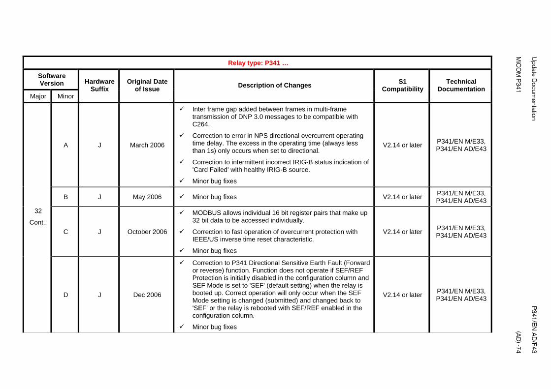
Update D
ocumentation
P
341/EN
AD
/F43
M
iCO
M P
341
(AD
) -74
Relay type: P341 …
Software Version
Major Minor
Hardware Suffix
Original Date of Issue
S1 Compatibility
Technical Documentation
Description of Changes
A J March 2006
Inter frame gap added between frames in multi-frame transmission of DNP 3.0 messages to be compatible with C264.
Correction to error in NPS directional overcurrent operating time delay. The excess in the operating time (always less than 1s) only occurs when set to directional.
Correction to intermittent incorrect IRIG-B status indication of 'Card Failed' with healthy IRIG-B source.
Minor bug fixes
V2.14 or later P341/EN M/E33, P341/EN AD/E43
B J May 2006 Minor bug fixes V2.14 or later P341/EN M/E33, P341/EN AD/E43
C J October 2006
MODBUS allows individual 16 bit register pairs that make up 32 bit data to be accessed individually.
Correction to fast operation of overcurrent protection with IEEE/US inverse time reset characteristic.
Minor bug fixes
V2.14 or later P341/EN M/E33, P341/EN AD/E43
32
Cont..
D J Dec 2006
Correction to P341 Directional Sensitive Earth Fault (Forward or reverse) function. Function does not operate if SEF/REF Protection is initially disabled in the configuration column and SEF Mode is set to 'SEF' (default setting) when the relay is booted up. Correct operation will only occur when the SEF Mode setting is changed (submitted) and changed back to 'SEF' or the relay is rebooted with SEF/REF enabled in the configuration column.
Minor bug fixes
V2.14 or later P341/EN M/E33, P341/EN AD/E43

Update D
ocumentation
P
341/EN
AD
/F43
M
iCO
M P
341
(AD
) -75
Relay type: P341 …
Software Version
Major Minor
Hardware Suffix
Original Date of Issue
S1 Compatibility
Technical Documentation
Description of Changes
F J May 2007
Correction to VT secondary ratio setting for 32 software relays, Vn = 380/480V rating. With a 1:1 VT ratio on a 380/480V P340 relay with 32 software installed after power up the analogue quantities are 4 times too large. The error is corrected by re-appying the VT secondary (which is showing the correct value) setting.
Local time zone adjustments for daylight saving time added to Date and Time menu
Minor bug fixes
V2.14 or later P341/EN M/E33, P341/EN AD/E43
G J Sept 2007
IEC 61850 communications added.
Support released for high break contacts and de-modulated IRIG-B in all P34x relays. P34x relays can be ordered with modulated or de-modulated IRIG-B and with 4 or 8 high break contacts depending on the model.
Minor bug fixes
V2.14 or later P341/EN M/E33, P341/EN AD/E43
H J Nov 2007
Correction to the CT ratio scaling for 32 software relays. If the CT ratio secondary settings are set to 5A and the relay rebooted, if the setting group is changed the CT secondary scaling reverts to 1A.
Minor bug fixes
V2.14 or later P341/EN M/E33, P341/EN AD/E43
32
Cont..
J J Dec 2007
IEC61850 communications added.
Support released for high break contacts and de-modulated IRIG-B in all P34x relays. P341 relays can be ordered with modulated or de-modulated IRIG-B and with 4 high break contacts.
Minor bug fixes
V2.14 or later P341/EN M/E33, P341/EN AD/E43
Apr 2011 Rebranded from AREVA to ALSTOM P341/ EN AD/F43

Update D
ocumentation
P
341/EN
AD
/F43
M
iCO
M P
341
(AD
) -76
Relay Software Version
01 02 03 04 05 06 07 30 31 32
01
02
03
04
05
06
07
30
31
32
Set
ting
File
Sof
twar
e V
ersi
on

Relay Software Version
01
02
03 04 05 06 07 30
31 32 A-H
32 J-
01
02
03
04
05
06
07
30
31
32 A-H
32 J-
PS
L F
ile S
oftw
are
Ver
sion
Note 1: 05, 06 PSL compatible with 07 PSL except for user alarm DDBs
Update D
ocumentation
P
341/EN
AD
/F43
M
iCO
M P
341
(AD
) -77

Relay Software Version
01 02 03 04 05
A-E 05 F-J
05K 06
A-E 06F
07 A-E
07F 30 31 32
A-E 32 F-J
01
02
03
04
05A-E
05F-J
05K
06A-E
06F
07A-E
07F
30
31
32 A-E
32 F-J
Men
u T
ext F
ile S
oftw
are
Ver
sion
� Menu text remains compatible within each software version (except 05/06/07) but is NOT compatible across different versions.
Update D
ocumentation
P
341/EN
AD
/F43
M
iCO
M P
341
(AD
) -78

Update Documentation P341/EN AD/F43 MiCOM P341
(AD) -79
ORDERING INFORMATION
P341 Generator Protection Relay P341
Vx Aux Rating
24-48 Vdc
48-110 Vdc, 30-100 Vac
110-250 Vdc, 100-240 Vac
1
2
3
I/n/Vn Rating
In=1A/5A, Vn=100/120V
In=1A/5A, Vn=380/480V
1
2
Hardware Options
Nothing 1
IRIG-B only (Modulated) 2
Fiber Optic Rear Comms Port 3
IRIG-B (Modulated) & Fiber Optic Rear Comms Port 4
Ethernet (100Mbps)** 6
2nd Rear Comms. Board* 7
IRIG-B* (Modulated) plus 2nd Rear Comms Board 8
Ethernet (100Mbps) + IRIG-B (Modulated)** A
Ethernet (100Mbps) + IRIG-B (De-modulated) ** B
IRIG-B (De-modulated) ** C
Product Specific
Size 40TE Case, No Option (8 Optos + 7 Relays) A
Size 40TE Case, 8 Optos + 7 Relays + CLIO * B
Size 40TE Case, 16 Optos + 7 Relays* C
Size 40TE Case, 8 Optos + 15 Relays* D
Size 40TE Case, 12 Optos + 11 Relays* E
Size 40TE Case, 8 Optos + 7 Relays + 4 Relays K
HB**
Note: HB = High Break
Protocol Options
K-Bus 1
IEC60870-5-103 (VDEW) 2
DNP3.0 3
IEC 61850 + Courier via rear EIA(RS)485 port 4
IEC 61850 + IEC 60870-5-103 via rear EIA(RS)485 port 6
Mounting
Panel Mounting M
Language Options
Multilingual - English, French, German, Spanish
Multilingual - English, French, German, Russian
0
5
Software Number
Unless specified the latest version will be delivered 32
Settings File
Default
Customer
0
1

P341/EN AD/F43 Update Documentation (AD) -80
MiCOM P341
Design Suffix
Original hardware A
Universal optos, new relays, power supply C
Phase 2 CPU J
Note Design Suffix
A = Original hardware (48V opto inputs only, lower contact rating, no I/O expansion available) C = Universal optos, new high capacity relays, new power supply J = Phase 2 CPU and front panel with 2 hotkeys and dual characteristic optos
* Not available in design suffix A relays
** Not available in design suffix A,B, C
Note Mounting For rack mounting assembled single rack frames and blanking plates are available


PXXX Product Description
GRID
Alstom Grid
© - ALSTOM 2011. ALSTOM, the ALSTOM logo and any alternative version thereof are trademarks and service marks of ALSTOM. The other names mentioned, registered or not, are the property of their respective companies. The technical and other data contained in this document is provided for information only. Neither ALSTOM, its officers or employees accept responsibility for, or should be taken as making any representation or warranty (whether express or implied), as to the accuracy or completeness of such data or the achievement of any projected performance criteria where these are indicated. ALSTOM reserves the right to revise or change this data at any time without further notice.
Alstom Grid Worldwide Contact Centre
www.alstom.com/grid/contactcentre/
Tel: +44 (0) 1785 250 070
www.alstom.com