mems-based deformable mirrors - thorlabs · pdf filea mems deformable mirror system, a...
TRANSCRIPT
2/2/2015 MEMS-Based Deformable Mirrors
http://www.thorlabs.us/newgrouppage9.cfm?objectgroup_id=3258 1/2
Related Items
Chat Live With Support Representative
>> MEMS-Based Deformable Mirrors
MEMS-Based Deformable Mirrors
Overview Specs Graphs Selecting a DM Types of Aberrations AO Tutorial Documents Feedback Tag Cloud
Click to EnlargeMulti-DM Model(140 Actuators)
Click for DetailsDM140-35-UP01 shownmounted in a KS2 Mirror
Mount.
DM Electrical Interface
Features
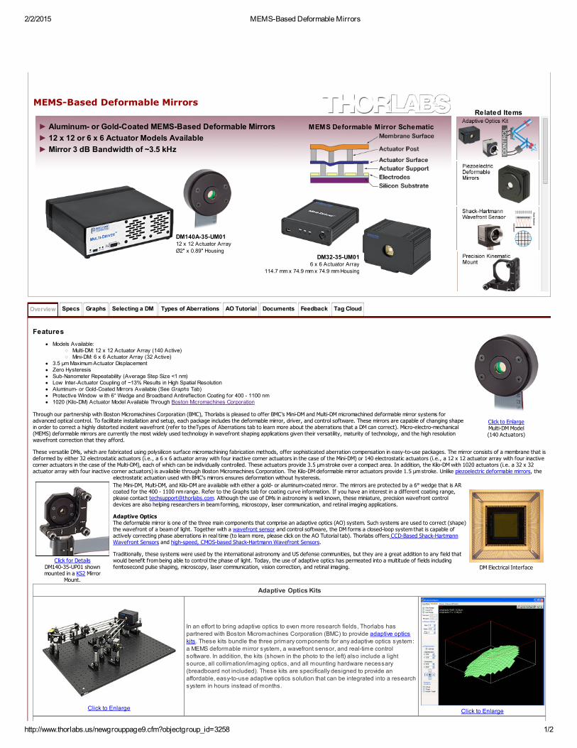
Models Available:Multi-DM: 12 x 12 Actuator Array (140 Active)Mini-DM: 6 x 6 Actuator Array (32 Active)
3.5 μm Maximum Actuator DisplacementZero HysteresisSub-Nanometer Repeatability (Average Step Size <1 nm)Low Inter-Actuator Coupling of ~13% Results in High Spatial ResolutionAluminum- or Gold-Coated Mirrors Available (See Graphs Tab)Protective Window w ith 6° Wedge and Broadband Antireflection Coating for 400 - 1100 nm1020 (Kilo-DM) Actuator Model Available Through Boston Micromachines Corporation
Through our partnership with Boston Micromachines Corporation (BMC), Thorlabs is pleased to offer BMC's Mini-DM and Multi-DM micromachined deformable mirror systems foradvanced optical control. To facilitate installation and setup, each package includes the deformable mirror, driver, and control software. These mirrors are capable of changing shapein order to correct a highly distorted incident wavefront (refer to theTypes of Aberrations tab to learn more about the aberrations that a DM can correct). Micro-electro-mechanical(MEMS) deformable mirrors are currently the most widely used technology in wavefront shaping applications given their versatility, maturity of technology, and the high resolutionwavefront correction that they afford.
These versatile DMs, which are fabricated using polysilicon surface micromachining fabrication methods, offer sophisticated aberration compensation in easy-to-use packages. The mirror consists of a membrane that isdeformed by either 32 electrostatic actuators (i.e., a 6 x 6 actuator array with four inactive corner actuators in the case of the Mini-DM) or 140 electrostatic actuators (i.e., a 12 x 12 actuator array with four inactivecorner actuators in the case of the Multi-DM), each of which can be individually controlled. These actuators provide 3.5 μm stroke over a compact area. In addition, the Kilo-DM with 1020 actuators (i.e. a 32 x 32actuator array with four inactive corner actuators) is available through Boston Micromachines Corporation. The Kilo-DM deformable mirror actuators provide 1.5 µm stroke. Unlike piezoelectric deformable mirrors, the
electrostatic actuation used with BMC's mirrors ensures deformation without hysteresis.
The Mini-DM, Multi-DM, and Kilo-DM are available with either a gold- or aluminum-coated mirror. The mirrors are protected by a 6° wedge that is ARcoated for the 400 - 1100 nm range. Refer to the Graphs tab for coating curve information. If you have an interest in a different coating range,please contact [email protected]. Although the use of DMs in astronomy is well known, these miniature, precision wavefront controldevices are also helping researchers in beam forming, microscopy, laser communication, and retinal imaging applications.
Adaptive OpticsThe deformable mirror is one of the three main components that comprise an adaptive optics (AO) system. Such systems are used to correct (shape)the wavefront of a beam of light. Together with a wavefront sensor and control software, the DM forms a closed-loop system that is capable ofactively correcting phase aberrations in real time (to learn more, please click on the AO Tutorial tab). Thorlabs offers CCD-Based Shack-HartmannWavefront Sensors and high-speed, CMOS-based Shack-Hartmann Wavefront Sensors.
Traditionally, these systems were used by the international astronomy and US defense communities, but they are a great addition to any field thatwould benefit from being able to control the phase of light. Today, the use of adaptive optics has permeated into a multitude of fields includingfemtosecond pulse shaping, microscopy, laser communication, vision correction, and retinal imaging.
Adaptive Optics Kits
Click to Enlarge
In an effort to bring adaptive optics to even more research fields, Thorlabs has
partnered with Boston Micromachines Corporation (BMC) to provide adaptive opticskits. These kits bundle the three primary components for any adaptive optics system:
a MEMS deformable mirror system, a wavefront sensor, and real-time control
software. In addition, the kits (shown in the photo to the left) also include a light
source, all collimation/imaging optics, and all mounting hardware necessary
(breadboard not included). These kits are specifically designed to provide anaffordable, easy-to-use adaptive optics solution that can be integrated into a research
system in hours instead of months.
Click to Enlarge
Aluminum- or Gold-Coated MEMS-Based Deformable Mirrors
12 x 12 or 6 x 6 Actuator Models Available
Mirror 3 dB Bandwidth of ~3.5 kHz
►
►
►
DM140A-35-UM0112 x 12 Actuator Array
Ø2" x 0.89" HousingDM32-35-UM01
6 x 6 Actuator Array
114.7 mm x 74.9 mm x 74.9 mm Housing
MEMS Deformable Mirror Schematic

2/2/2015 MEMS-Based Deformable Mirrors
http://www.thorlabs.us/newgrouppage9.cfm?objectgroup_id=3258 2/2
Related White Papers
A list of MEMS and Adaptive Optics publications is available on BMC's website.
Overview Specs Graphs Selecting a DM Types of Aberrations AO Tutorial Documents Feedback Tag Cloud
Item # DM32-35-UM01 DM32-35-UP01 DM140A-35-UM01 DM140A-35-UP01 Kilo-DM
Actuator Array 6 x 6 (32 Active) 12 x 12 (140 Active) 32 x 32 (1020 Active)
Actuator Stroke (Max) 3.5 µm 1.5 µm
Actuator Pitch 400 µm 300 µm
Clear Aperture 2.0 mm x 2.0 mm 4.4 mm x 4.4 mm 9.3 mm x 9.3 mm
Mirror Coating Gold Aluminum Gold Aluminum Gold or Aluminum
Average Step Size <1 nm
Hysteresis None
Fill Factor >99%
Acceptance Angle - ±18° -
Mechanical Response Time (10% - 90%) <100 μs (~3.5 kHz) <20 μs
Surface Quality <20 nm (RMS) <30 nm (RMS) <20 nm (RMS)
Cable Length (from Mirror to Driver) 2 m
Driver Specifications
Frame Rate (Max) 8 kHz (34 kHz Bursts) Up to 60 kHz
Resolution 14 Bit
Driver Dimensions4.0" x 5.25" x 1.25"
(102 mm x 133 mm x 32 mm)9.0" x 7.0" x 2.5"
(229 mm x 178 mm x 64 mm)19.0" x 18.5" x 5.25"
(483 mm x 470 mm x 133 mm)
Computer Interface USB 2.0 PCI Card
a. The Kilo-DM is available through Boston Micromachines Corporation (BMC).b. The four corner actuators are inactive.c. For a graph of mirror delf lection versus voltage and the RMS shape error, see the Graphs tab.d. The interactuator coupling is about 13% for these mirrors, w hich w ill introduce some variation in the step size that is dependent on the position of the adjacent actuators.e. The f ill factor is less than 100% due to the print-through of the etch access holes (about Ø2 µm) used in the fabrication process.
a
b b b
c
d
e

2/2/2015 MEMS-Based Deformable Mirrors
http://www.thorlabs.us/newgrouppage9.cfm?objectgroup_id=3258 1/2
Overview Specs Graphs Selecting a DM Types of Aberrations AO Tutorial Documents Feedback Tag Cloud
Click to Enlarge
Reflectance of the Metallic Mirror CoatingClick to Enlarge
Reflectance of the AR-Coated, 6° Wedged Window
Coating Curves
Depicted here are typical reflectance plots for aluminum- and gold-coated surfaces (without the protective window) as well as the AR coating curve for the protective 6° wedged window. The data for the unprotectedaluminum and gold coatings was obtained with using unpolarized light that was incident at 45°
Actuator Deflection
The plot below to the lower left shows the typical deflection of a single actuator and a 4 x 4 region of actuators in the mirror as a function of the input voltage. This graph is included on the data sheet included witheach deformable mirror. A polynomial fit has been applied to each set of points and the coefficients are provided on the data sheet for each mirror. The plot to the lower right shows the error in the mirror shape whencompared to the shape defined by different Zernike coefficients for different peak-to-valley amplitudes of the wavefront distortion.
Click to EnlargeTypical deflection of a single actuator and a 4 x 4 region of actuators as a function of
voltage.
Click to EnlargeResidual error of the mirror shape compared to different Zernike functions for a range of wavefront
distortion amplitudes.

2/2/2015 MEMS-Based Deformable Mirrors
http://www.thorlabs.us/newgrouppage9.cfm?objectgroup_id=3258 2/2
Overview Specs Graphs Selecting a DM Types of Aberrations AO Tutorial Documents Feedback Tag Cloud
DM Electrical Interface
ConsiderationsIdeally, the deformable mirror needs to assume a surface shape that is complementary to, but half the amplitude of, the aberration profile in order to compensate for the aberrationsand yield a flat wavefront. However, the actual range of wavefronts that can be corrected by a particular deformable mirror is limited by several factors:
Actuator stroke is another term for the dynamic range (i.e., the maximum displacement) of the DM actuators and is typically measured in microns. Inadequate actuatorstroke leads to poor performance by limiting aberration amplitudes that may be compensated, preventing the convergence of the control loop.The number of actuators limits the degrees of freedom of the w avefront control system, and therefore the complexity of the w avefront that may be corrected.Hysteresis in piezoelectric deformable mirrors means that the displacement of a mirror segment at a given voltage is different if that voltage is approached from a highervoltage compared to a low er voltage. Hysteresis in piezoelectric deformable mirrors can be signif icant, w hile MEMS-based deformable mirrors are inherently hysteresis-free.The deformable mirror speed is important if you are trying to correct for rapidly changing w avefronts. For mirrors that exhibit hysteresis, the control softw are w ill need tocalculate the correct voltage changes to produce the desired mirror displacement, w hich can low er the mirror speed.
The first three considerations are physical limitations of the deformable mirror itself, whereas the last consideration may be a limitation of the control software and/or a physicallimitation of the mirror itself. Additionally, the wavelength range of the deformable mirror coating and any protective windows installed in the mirror head must be appropriate for theapplication wavelength.
ComparisonsThorlabs' piezoelectric deformable mirrors provide a larger stroke, and therefore are able to correct for larger wavefront deviations, than our MEMS-based deformable mirrors. However, they contain a lower densityof actuators over the active area of the mirror than the MEMS-based Multi DMs below, which means they cannot correct wavefront deviations on as fine of a spatial scale as the MEMs-based DMs.
To correct for both large amplitude and small spatial scale wavefront distortions, consider using a piezoelectric and MEMS-based deformable mirror in tandem, typically referred to in the literature as a woofer-tweeterconfiguration. The piezoelectric deformable mirror can correct for the tip, tilt, and lower order (lower spatial frequency) wavefront distortions, while the MEMS-based device compensates for higher order (higherspatial frequency) wavefront distortions. In nature, lower order wavefront distortions typically have larger magnitudes than do higher order wavefront distortions. Therefore, the combination of our lower actuatorcount, larger displacement, piezo-based DM and the higher actuator count, smaller displacement, MEMs-based DM is well suited to be used in a woofer-tweeter configuration.
Overview Specs Graphs Selecting a DM Types of Aberrations AO Tutorial Documents Feedback Tag Cloud
Ideally, an optical image-forming system will produce a unique image point for each object point. Any departures from this ideal theory of Gaussian (also known as paraxial or first-order) Optics are known asaberrations and can be categorized into two main types: monochromatic (single color) aberrations and chromatic (varying wavelength) aberrations. When aberrations are present, the peak intensity will be reducedand the image or laser beam propagating to a target will be blurred. Below, we will take a look at the seven primary types of aberrations, five of which are of the monochromatic variety and two of which are of thechromatic variety. Deformable mirrors are capable of removing all types of monochromatic aberrations from a wavefront to allow for the formation of an ideal, diffraction-limited image, even if optics withoutdiffraction-limited performance are being used in the optical system.
Monochromatic Aberrations
There are five primary monochromatic aberrations, which can be further divided into two subgroups: those that deteriorate the image (spherical aberration, coma, and astigmatism) and those that deform the image(field curvature and distortion). These aberrations are a direct result of departures from first-order (i.e., sinθ≈θ) theory, which assumes the light rays make small angles with the principal axis. As soon as one wantsto consider light rays incident on the periphery of a lens, the statement sinθ≈θ, which forms the basis of paraxial optics, is no longer satisfactory and one must consider more terms in the expansion:
The five primary monochromatic aberrations were first studied by Ludwig von Seidel, and hence, they are frequently referred to as the Seidel aberrations. Please note that since the expansion of sinθ is an infinitesum, the five monochromatic aberrations discussed below are not the only ones possible; there are additional higher-order aberrations that make smaller contributions to image degradation. The surface of thedeformable mirror can be altered to accommodate all of these types of monochromatic aberrations.
1) Spherical Aberrations
For parallel incoming light rays, an ideal lens will be able to focus the rays to a point on the optical axis as shown in Fig. 1a; consequently, under ideal circumstances, the image of a point source that is located on the
optical axis will be a bright circular disk surrounded by faint rings (see the Airy diffraction pattern shown in Fig. 1b). However, in reality, the light rays that strike a spherical converging lens far from the principal axiswill be focused to a point that is closer to the lens than those light rays that strike the spherical lens near the principal axis (see Fig. 1c). Consequently, there is no single focus for a spherical lens, and the image willappear to be blurred; instead of having an Airy diffraction pattern in which nearly all the light is contained in a central bright circular spot, spherical aberration will redistribute some of the light from the central disk tothe surrounding rings (see Fig. 1d), thereby reducing image contrast. Whenever spherical aberration is present, the best focus for an uncorrected lens will be somewhere between the focal planes of the peripheraland axial rays. Please note that spherical aberration only pertains to object points that are located on the optical axis.
Figure 1. Comparison of an ideal situation to one in which spherical aberration is present. (a) For a perfect lens, all incoming light rays get focused to a singlepoint. (b) The Airy diffraction pattern corresponding to a point source that has been imaged by a perfect lens consists of a bright central spot surrounded byfaint concentric rings. (c) For a real lens, light incident on the edges of a lens is refracted more than the light striking the center of the lens, and thus, there isnot one unique focal point for all incident light rays. (d) Spherical aberration degrades resolution by redistributing some of the light from the central bright spot
to the surrounding concentric rings.
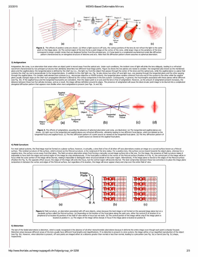
2) Coma
Coma, or comatic aberration, is an image-degrading aberration associated with object points that are even slightly off axis. When an off-axis bundle of light is incident on a lens, the light will undergo differentamounts of refraction depending on where it strikes the lens (see Fig. 2a); as a result, each annulus of light will focus onto the image plane at a slightly different height and with a different spot size (see Fig. 2b),thereby leading to different transverse magnifications. The resulting image of a point source, which is shown in Fig. 2c, is a complicated asymmetrical diffraction pattern with a bright central core and a triangular flarethat departs drastically from the classical Airy pattern shown in Fig 1b above. The elongated comet-like structure from which this type of aberration takes its name can extend either towards or away from the opticalaxis depending on whether the comatic aberration is negative or positive, respectively. Due to the asymmetry that coma causes in images, many consider it to be the worst type of aberration.
2/2/2015 MEMS-Based Deformable Mirrors
http://www.thorlabs.us/newgrouppage9.cfm?objectgroup_id=3258 2/3
Figure 2. The effects of positive coma are shown. (a) When a light source is off-axis, the various portions of the lens do not refract the light to the samepoint on the image plane. (b) The central region of the lens forms a point image at the vertex of the cone, while larger rings on the periphery of the lenscorrespond to larger comatic circles that are displaced farther from the principal axis. (c) Coma leads to a complicated asymmetrical comet-like diffraction
pattern characterized by an elongated structure of blotches and arcs. Note that the diffraction pattern shown assumes no spherical aberration.
3) Astigmatism
Astigmatism, like coma, is an aberration that arises when an object point is moved away from the optical axis. Under such conditions, the incident cone of light will strike the lens obliquely, leading to a refractedwavefront characterized by two principal curvatures that ultimately determine two different focal image points. Figure 3a shows the two planes one needs to consider: the tangential (also known as the meridional)plane and the sagittal plane; the tangential plane is defined by the chief ray (i.e., the light ray from the object that passes through the center of the lens) and the optical axis, while the sagittal plane is a plane thatcontains the chief ray and is perpendicular to the tangential plane. In addition to the chief light ray, Fig. 3a also shows two other off-axis light rays, one passing through the tangential plane and the other passingthrough the sagittal plane. For complex multi-element lens systems (e.g., microscope objective or ASOM system), the tangential plane remains coherent from one end of the system to the other while the sagittalplane usually changes slope as the chief ray’s propagation direction is altered by the various components in the lens system. Consequently, in general, the focal lengths associated with these planes will be different(see Fig. 3b). If the sagittal focus and the tangential focal points are coincident, then the object point is on axis and the lens is free of astigmatism. However, as the amount of astigmatism present increases, thedistance between these two foci will also increase, and as a result, the image will lose definition around its edges. The presence of astigmatism will cause the ideal circular point image to be blurred into a complicatedelongated diffraction pattern that appears more linelike when more astigmatism is present (see Figs. 3c and 3d).
Figure 3. The effects of astigmatism, assuming the absence of spherical aberration and coma, are illustrated. (a) The tangential and sagittal planes areshown. (b) Light rays in the tangential and sagittal planes are refracted differently, ultimately leading to two different focal planes, which are labeled as the
tangential focus and sagittal focus. (c) The Airy diffraction pattern of a point source as viewed at the tangential focal plane. (d) The Airy diffraction pattern ofa point source as viewed at the sagittal focal plane.
4) Field Curvature
For most optical systems, the final image must be formed on a planar surface; however, in actuality, a lens that is free of all other off-axis aberrations creates an image on a curved surface known as a Petzvalsurface. This nominal curvature of this surface, which is known as the Petzval curvature, is the reciprocal of the lens radius. For a positive lens, this surface curves inward towards the object plane, whereas for anegative lens, the surface curves away from that plane. The field curvature aberration arises from forcing a naturally curved image surface into a flat one. For the image, the presence of field curvature makes itimpossible to have both the edges and central region of the image be crisp simultaneously. If the focal plate is shifted to the vertex of the Petzval surface (Position A in Fig. 4), the central part of the image will be infocus while the outer portion of the image will be blurred, making it impossible to distinguish minor structural details in this outer region. Alternatively, if the image plane is moved to the edges of the Petzval surface(Position B in Fig. 4), the opposite effect occurs; the edges of the image will come into focus, but the central region will become blurred. The best compromise between these two extremes is to place the image planesomewhere in between the vertex and edges of the Petzval surface, but regardless of its location, the image will never appear sharp and crisp over the entire field of view.
Figure 4. Field curvature, an aberration associated with off-axis objects, arises because the best image is not formed on the paraxial image plane but on aparabolic surface called the Petzval surface. (a) Depending on the location of the focal plane along the optic axis, either the central (if at location A) or
peripheral (if at location B) portions of the field of view will be in focus but not both. (b) The central portion of the image will be crisp if the image plane islocated at position A. (c) The edges of the image will be sharply in focus if the image plane is located at position B.
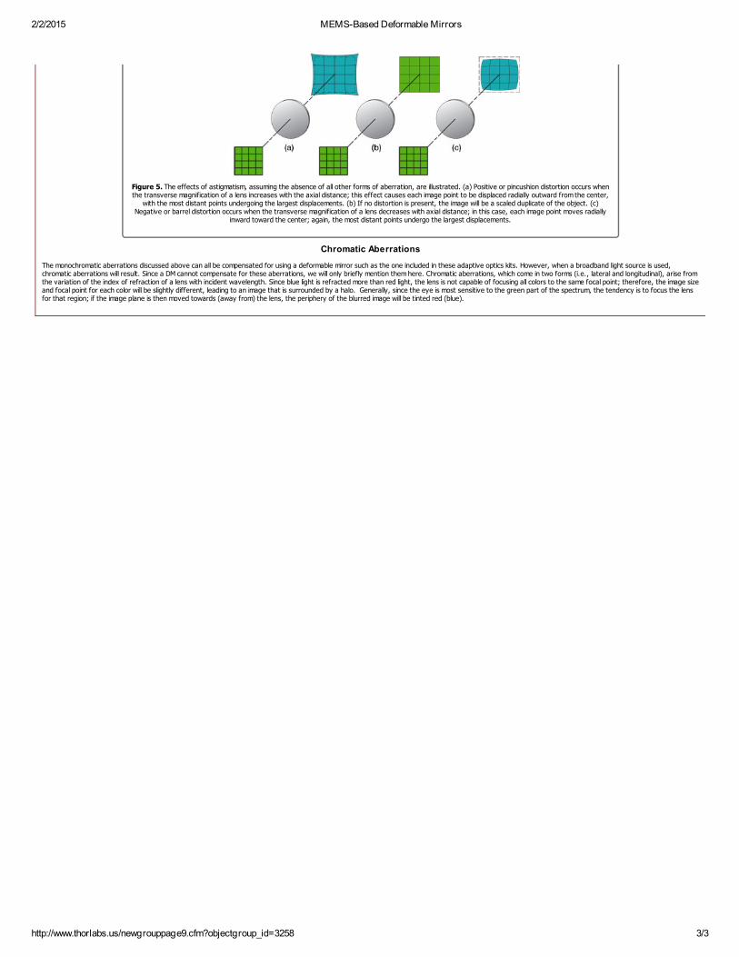
5) Distortion
The last of the Seidel aberrations is distortion, which is easily recognized in the absence of all other monochromatic aberrations because it deforms the entire image even though each point is sharply focused.Distortion arises because different areas of the lens usually have different focal lengths and magnifications. If no distortion is present in a lens system, the image will be a true magnified reproduction of the object(see Fig. 5b). However, when distortion is present, off-axis points are imaged either at a distance greater than normal or less than normal, leading to a pincushion (see Fig. 5a) or barrel (see Fig. 5c) shape,respectively.
2/2/2015 MEMS-Based Deformable Mirrors
http://www.thorlabs.us/newgrouppage9.cfm?objectgroup_id=3258 3/3
Figure 5. The effects of astigmatism, assuming the absence of all other forms of aberration, are illustrated. (a) Positive or pincushion distortion occurs whenthe transverse magnification of a lens increases with the axial distance; this effect causes each image point to be displaced radially outward from the center,
with the most distant points undergoing the largest displacements. (b) If no distortion is present, the image will be a scaled duplicate of the object. (c)Negative or barrel distortion occurs when the transverse magnification of a lens decreases with axial distance; in this case, each image point moves radially
inward toward the center; again, the most distant points undergo the largest displacements.
Chromatic Aberrations
The monochromatic aberrations discussed above can all be compensated for using a deformable mirror such as the one included in these adaptive optics kits. However, when a broadband light source is used,chromatic aberrations will result. Since a DM cannot compensate for these aberrations, we will only briefly mention them here. Chromatic aberrations, which come in two forms (i.e., lateral and longitudinal), arise fromthe variation of the index of refraction of a lens with incident wavelength. Since blue light is refracted more than red light, the lens is not capable of focusing all colors to the same focal point; therefore, the image sizeand focal point for each color will be slightly different, leading to an image that is surrounded by a halo. Generally, since the eye is most sensitive to the green part of the spectrum, the tendency is to focus the lensfor that region; if the image plane is then moved towards (away from) the lens, the periphery of the blurred image will be tinted red (blue).

2/2/2015 MEMS-Based Deformable Mirrors
http://www.thorlabs.us/newgrouppage9.cfm?objectgroup_id=3258 1/3
Overview Specs Graphs Selecting a DM Types of Aberrations AO Tutorial Documents Feedback Tag Cloud
Introduction:Adaptive optics (AO) is a rapidly growing multidisciplinary field encompassing physics, chemistry, electronics, and computer science. AO systems are used to correct (shape) the wavefront of a beam of light.Historically, these systems have their roots in the international astronomy and US defense communities. Astronomers realized that if they could compensate for the aberrations caused by atmospheric turbulence,they would be able to generate high resolution astronomical images; with sharper images comes an additional gain in contrast, which is also advantageous for astronomers since it means that they can detect fainterobjects that would otherwise go unnoticed. While astronomers were trying to overcome the blurring effects of atmospheric turbulence, defense contractors were interested in ensuring that photons from their high-power lasers would be correctly pointed so as to destroy strategic targets. More recently, due to advancements in the sophistication and simplicity of AO components, researchers have utilized these systems to makebreakthroughs in the areas of femtosecond pulse shaping, microscopy, laser communication, vision correction, and retinal imaging. Although dramatically different fields, all of these areas benefit from an AO systemdue to undesirable time-varying effects.
Typically, an AO system is comprised from three components: (1) a wavefront sensor, which measures these wavefront deviations, (2) a deformable mirror, which can change shape in order to modify a highlydistorted optical wavefront, and (3) real-time control software, which uses the information collected by the wavefront sensor to calculate the appropriate shape that the deformable mirror should assume in order tocompensate for the distorted wavefront. Together, these three components operate in a closed-loop fashion. By this, we mean that any changes caused by the AO system can also be detected by that system. Inprinciple, this closed-loop system is fundamentally simple; it measures the phase as a function of the position of the optical wavefront under consideration, determines its aberration, computes a correction, reshapesthe deformable mirror, observes the consequence of that correction, and then repeats this process over and over again as necessary if the phase aberration varies with time. Via this procedure, the AO system isable to improve optical resolution of an image by removing aberrations from the wavefront of the light being imaged.
The Wavefront Sensor:The role of the wavefront sensor in an adaptive optics system is to measure the wavefront deviations from a reference wavefront. There are three basic configurations of wavefront sensors available: Shack-Hartmann wavefront sensors, shearing interferometers, and curvature sensors. Each has its own advantages in terms of noise, accuracy, sensitivity, and ease of interfacing it with the control software anddeformable mirror. Of these, the Shack-Hartmann wavefront sensor has been the most widely used.
A Shack-Hartmann wavefront sensor uses a lenslet array to divide an incoming beam into a bunch of smaller beams, each of which is imaged onto a CCD camera, which is placed at the focal plane of the lenslet array.If a uniform plane wave is incident on a Shack-Hartmann wavefront sensor (refer to Fig. 1), a focused spot is formed along the optical axis of each lenslet, yielding a regularly spaced grid of spots in the focalplane. However, if a distorted wavefront (i.e., any non-flat wavefront) is used, the focal spots will be displaced from the optical axis of each lenslet. The amount of shift of each spot’s centroid is proportional to the
local slope (i.e., tilt) of the wavefront at the location of that lenslet. The wavefront phase can then be reconstructed (within a constant) from the spot displacement information obtained (see Fig. 2).
Figure 1. When a planar wavefront is incident on the Shack-Hartmann wavefront sensor's microlens array, the light imaged on the CCD sensor will display a regularly spaced grid of spots. If,however, the wavefront is aberrated, individual spots will be displaced from the optical axis of each lenslet; if the displacement is large enough, the image spot may even appear to be missing. This
information is used to calculate the shape of the wavefront that was incident on the microlens array.
Figure 3. Dynamic range and measurement sensitivity are competing properties of a Shack-Hartmannwavefront sensor. Here, f, Δy, and d represent the focal length of the lenslet, the spot displacement,and the lenslet diameter, respectively. The equations provided for the measurement sensitivity θand the dynamic range θ are obtained using the small angle approximation. θ is the minimumwavefront slope that can be measured by the wavefront sensor. The minimum detectable spotdisplacement Δy depends on the pixel size of the photodetector, the accuracy of the centroid
algorithm, and the signal to noise ratio of the sensor. θ is the maximum wavefront slope that can bemeasured by the wavefront sensor and corresponds to a spot displacement of Δy , which is equal tohalf of the lenslet diameter. Therefore, increasing the sensitivity will decrease the dynamic range andvice versa.
Figure 2. Two Shack-Hartmann wavefront sensor screen captures are shown: the spot field (left-hand frame) and the calculated wavefront based on that spot field information (right-hand frame).
The four parameters that greatly affect the performance of a given Shack-Hartmann wavefrontsensor are the number of lenslets (or lenslet diameter, which typically ranges from ~100 – 600μm), dynamic range, measurement sensitivity, and the focal length of the lenslet array (typicalvalues range from a few millimeters to about 30 mm). The number of lenslets restricts themaximum number of Zernike coefficients that a reconstruction algorithm can reliably calculate;studies have found that the maximum number of coefficients that can be used to represent theoriginal wavefront is approximately the same as the number of lenslets. When selecting thenumber of lenslets needed, one must take into account the amount of distortion s/he is trying tomodel (i.e., how many Zernike coefficients are needed to effectively represent the true waveaberration). When it comes to measurement sensitivity θ and dynamic range θ , these arecompeting specifications (see Fig. 3 below). The former determines the minimum phase that canbe detected while the latter determines the maximum phase that can be measured.
A Shack-Hartmann sensor’s measurement accuracy (i.e., the minimum wavefront slope that canbe measured reliably) depends on its ability to precisely measure the displacement of a focusedspot with respect to a reference position, which is located along the optical axis of the lenslet. Aconventional algorithm will fail to determine the correct centroid of a spot if it partially overlapsanother spot or if the focal spot of a lenslet falls outside of the area of the sensor assigned todetect it (i.e., spot crossover). Special algorithms can be implemented to overcome theseproblems, but they limit the dynamic range of the sensor (i.e., the maximum wavefront slopethat can be measured reliably). The dynamic range of a system can be increased by using alenslet with either a larger diameter or a shorter focal length. However, the lenslet diameter istied to the needed number of Zernike coefficients; therefore, the only other way to increase thedynamic range is to shorten the focal length of the lenslet, but this in turn, decreases the
measurement sensitivity. Ideally, choose the longest focal length lens that meets both thedynamic range and measurement sensitivity requirements.
The Shack-Hartmann wavefront sensor is capable of providing information about the intensityprofile as well as the calculated wavefront. Be careful not to confuse these. The left-hand frameof Fig. 4 shows a sample intensity profile, whereas the right-hand frame shows thecorresponding wavefront profile. It is possible to obtain the same intensity profile from variouswavefuncton distributions.
min
max min
min
max
max
min max

2/2/2015 MEMS-Based Deformable Mirrors
http://www.thorlabs.us/newgrouppage9.cfm?objectgroup_id=3258 2/3
Figure 4. Several pieces of information are provided by the Shack-Hartmann wavefront sensor, including information about the total power at each lenslet and the calculated wavefront distributionpresent. Here, the left-hand frame shows a sample intensity profile, while the right-hand frame shows the corresponding wavefront.
The Deformable Mirror:The deformable mirror (DM) changes shape in response to position commands in order to compensate for the aberrations measured by the Shack-Hartmann wavefront sensor (refer to the Types of Aberrations tab tolearn more about the aberrations that the DM can correct). Ideally, it will assume a surface shape that is conjugate to the aberration profile (see Fig. 5). In many cases, the surface profile is controlled by anunderlying array of actuators that move in and out in response to an applied voltage. Deformable mirrors come in several different varieties, but the two most popular categories are segmented and continuous (seeFig. 6). Segmented mirrors are comprised from individual flat segments that can either move up and down (if each segment is controlled by just one actuator) or have tip, tilt, and piston motion (if each segment iscontrolled by three actuators). These mirrors are typically used in holography and for spatial light modulators. Advantages of this configuration include the ability to manufacture the segments to tight tolerances, theelimination of coupling between adjacent segments of the DM since each acts independently, and the number of degrees of freedom per segment. However, on the down side, the regularly spaced gaps between thesegments act like a diffraction pattern, thereby introducing diffractive modes into the beam. In addition, segmented mirrors require more actuators than continuous mirrors to compensate for a given incomingdistorted wavefront. To address the optical problems with segmented DMs, continuous faceplate DMs (such as those included in our AO Kits) were fabricated. They offer a higher fill factor (i.e., the percentage of themirror that is actually reflective) than their segmented counterparts. However, their drawback is that the actuators are mechanically coupled. Therefore, when one actuator moves, there is some finite response alongthe entire surface of the mirror. The 2D shape of the surface caused by displacing one actuator is called the influence function for that actuator. Typically, adjacent actuators of a continuous DM are displaced by 10-20% of the actuation height; this percentage is known as the actuator coupling. Note that segmented DMs exhibit zero coupling but that isn’t necessarily desirable.
Figure 5. The aberration compensation capabilities of a flat and MEMS deformable mirror are compared. (a) If an unabberated wavefront is incident on a flat mirror surface, the reflected wavefrontwill remain unabberated. (b) A flat mirror is not able to compensate for any deformations in the wavefront; therefore, an incoming highly aberrated wavefront will retain its aberrations upon
reflection. (c) A MEMS deformable mirror is able to modify its surface profile to compensate for aberrations; the DM assumes the appropriate conjugate shape to modify the highly aberrated incidentwavefront so that it is unaberrated upon reflection.
Figure hows a screen shot of the AO kit softwaredepicting the DM surface, whereas the frame on the right, which was obtained through quasi-dark field illumination, shows the actual DM surface when programmed to these settings. Notethat the white light source used for illumination is visible in the lower right-hand corner of thephotograph.
Figure 6. Cross sectional schematics of the main components of BMC's continuous (left) and segmented (right) MEMS deformable mirrors.

2/2/2015 MEMS-Based Deformable Mirrors
http://www.thorlabs.us/newgrouppage9.cfm?objectgroup_id=3258 3/3
Based on your currency / country selection, your order w ill ship from Newton, New Jersey
+1 Qty Docs Part Number - Universal/Imperial Price Available / Ships
DM32-35-UM01 Mini-DM 6 x 6 Deformable Mirror with Gold Coating $7,500.00 Today
DM32-35-UP01 Mini-DM 6 x 6 Deformable Mirror with Aluminum Coating $7,500.00 Lead Time
DM140A-35-UM01 Multi-DM 12 x 12 Deformable Mirror with Gold Coating $17,500.00 Today
DM140A-35-UP01 Multi-DM 12 x 12 Deformable Mirror with Aluminum Coating $17,500.00 Today
Add To Cart
Additional Adaptive OpticsAdaptive Optics Kits
Our Life Science Catalog
Piezoelectric Deformable Mirrors
MEMS-Based Deformable Mirrors
CCD-Based Shack-Hartmann Wavefront Sensor
Fast CMOS-Based Shack-Hartmann Wavefront Sensor
Application Articles
Log In | My Account | Contact Us | Privacy Policy | Home | Site Index
Regional Websites: East Coast US | Europe | Asia | China | Japan
Copyright 1999-2015 Thorlabs, Inc.
Sales: 1-973-579-7227
Technical Support: 1-973-300-3000
Figure 7. A cross-like pattern is created on the DM surface by applying the voltages necessaryfor maximum deflection of the 44 actuators that comprise the middle two rows and middle twocolumns of the array. The frame on the left shows a screen shot of the AO kit softwaredepicting the DM surface, whereas the frame on the right, which was obtained through quasi-dark field illumination, shows the actual DM surface when programmed to these settings. Notethat the white light source used for illumination is visible in the lower right-hand corner of thephotograph.
Figure 6. Cross sectional schematics of the main components of BMC's continuous (left) and segmented (right) MEMS deformable mirrors.
The range of wavefronts that can be corrected by a particular DM is limited by the actuator stroke and resolution, the number and distribution of actuators, and the model used to determine the appropriate controlsignals for the DM; the first two are physical limitations of the DM itself, whereas the last one is a limitation of the control software. The actuator stroke is another term for the dynamic range (i.e., the maximumdisplacement) of the DM actuators and is typically measured in microns. Inadequate actuator stroke leads to poor performance and can prevent the convergence of the control loop. The number of actuatorsdetermines the number of degrees of freedom that the mirror can correct for. Although many different actuator arrays have been proposed, including square, triangular, and hexagonal, most DMs are built withsquare actuator arrays, which are easy to position on a Cartesian coordinate system and map easily to the square detector arrays on the wavefront sensors. To fit the square array on a circular aperture, the corneractuators are sometimes removed (e.g., the deformable mirror included with the AOK1-UM01 or AOK1-UP01 has a 12 x 12 actuator configuration but only 140 actuators since the corner ones are not used). Althoughmore actuators can be placed within a given area using some of the other configurations, the additional fabrication complexity usually does not warrant that choice.
Figure 7 (left frame) shows a screen shot of a cross formed on the 12 x 12 actuator array of the DMincluded with the adaptive optics kit. To create this screen shot, the voltages applied to the middle tworows and middle two columns of actuators were set to cause full deflection of the mirror membrane. Inaddition to the software screen shot depicting the DM surface, quasi-dark field illumination was used toobtain a photograph of the actual DM surface when programmed to these settings (see Fig. 7, rightframe)
The Control Software:In an adaptive optics setup, the control software is the vital link between the wavefront sensor and thedeformable mirror. It converts the wavefront sensor’s electrical signals, which are proportional to theslope of the wavefront, into compensating voltage commands that are sent to each actuator of the DM.The closed-loop bandwidth of the adaptive optics system is directly related to the speed and accuracywith which this computation is done, but in general, these calculations must occur on a shorter time scalethan the aberration fluctuations.
In essence, the control software uses the spot field deviations to reconstructs the phase of the beam(in this case, using Zernike polynomials) and then sends conjugate commands to the DM. A least-squaresfitting routine is applied to the calculated wavefront phase in order to determine the effective Zernikepolynomial data outputted for the end user. Although not the only form possible, Zernike polynomialsprovide a unique and convenient way to describe the phase of a beam. These polynomials form anorthogonal basis set over a unit circle with different terms representing the amount of focus, tilt,astigmatism, comma, et cetera; the polynomials are normalized so that the maximum of each term(except the piston term) is +1, the minimum is –1, and the average over the surface is always zero. Furthermore, no two aberrations ever add up to a third, thereby leaving no doubt about the type ofaberration that is present.