mems deformable mirror technology for exoplanet … deformable mirror technology for exoplanet...
TRANSCRIPT
MEMS Deformable Mirror Technology for Exoplanet Imaging Instrumentation
Paul BierdenBoston Micromachines Corporation, Cambridge, MA 02138Boston University, Boston, MA 02215
Exoplanet Imaging and Characterization: Coherent Differential Imaging and Signal Detection Statistics - Part 2
December 5 - 8, 2016California Institute of Technology - Pasadena, CA 91125

Outline• BMC DM Technology• Mirror technology programs• Space qualification programs• DMs in telescopes
• Ground• Space
• Next steps for scaling DM actuator count

Outline• BMC DM Technology• Mirror technology programs• Space qualification programs• DMs in telescopes
• Ground• Space
• Next steps for scaling DM actuator count
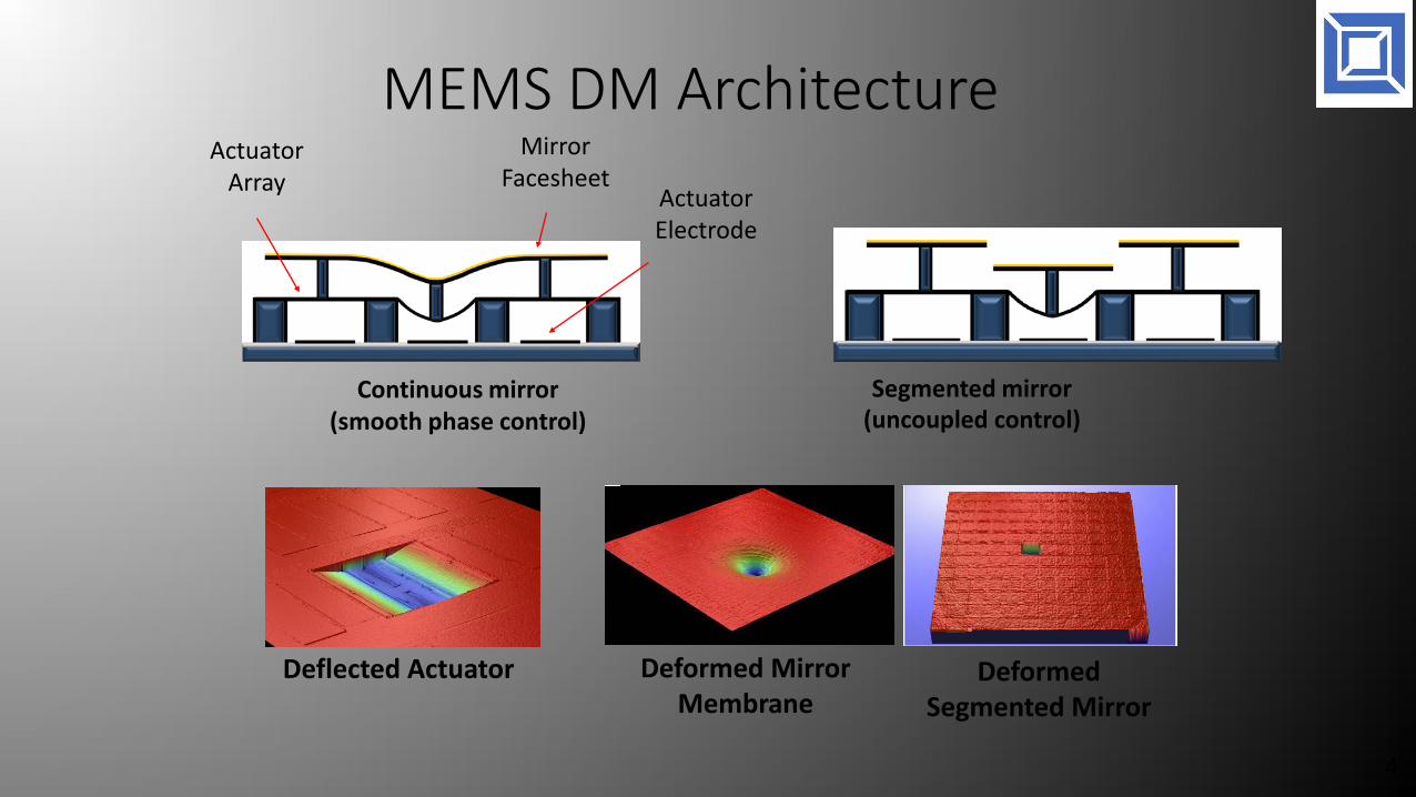
MEMS DM Architecture
4
Deflected Actuator Deformed Mirror Membrane
ActuatorArray
Mirror Facesheet
Actuator Electrode
Continuous mirror (smooth phase control)
Segmented mirror(uncoupled control)
Deformed Segmented Mirror

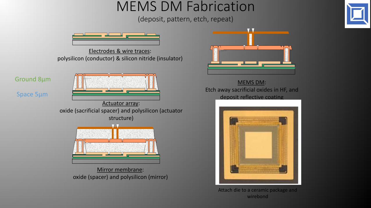
MEMS DM Fabrication (deposit, pattern, etch, repeat)
The picture can't be displayed.
Actuator array: oxide (sacrificial spacer) and polysilicon (actuator
structure)
MEMS DM:Etch away sacrificial oxides in HF, and
deposit reflective coating
The picture can't be displayed.
The picture can't be displayed.
Mirror membrane: oxide (spacer) and polysilicon (mirror)
Electrodes & wire traces: polysilicon (conductor) & silicon nitride (insulator)
Attach die to a ceramic package and wirebond
Ground 8µm
Space 5µm
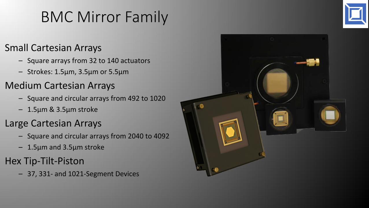
BMC Mirror Family
Small Cartesian Arrays– Square arrays from 32 to 140 actuators– Strokes: 1.5µm, 3.5µm or 5.5µm
Medium Cartesian Arrays– Square and circular arrays from 492 to 1020 – 1.5µm & 3.5µm stroke
Large Cartesian Arrays– Square and circular arrays from 2040 to 4092 – 1.5µm and 3.5µm stroke
Hex Tip-Tilt-Piston– 37, 331- and 1021-Segment Devices
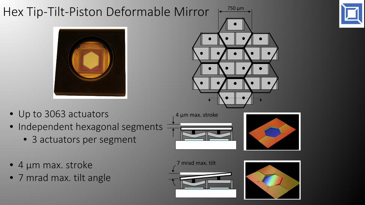
Hex Tip-Tilt-Piston Deformable Mirror
• Up to 3063 actuators• Independent hexagonal segments
• 3 actuators per segment
• 4 µm max. stroke• 7 mrad max. tilt angle
750 µm
4 µm max. stroke
7 mrad max. tilt
Outline• BMC DM Technology• Mirror technology programs• Space qualification programs• DMs in telescopes
• Ground• Space
• Next steps for scaling DM actuator count
Funded Technology Research
Over the past years BMC has received funding for the improvement of MEMS DM for space applications
• Topography• Yield• Reliability• Reduced operating voltage• Hex TTP development
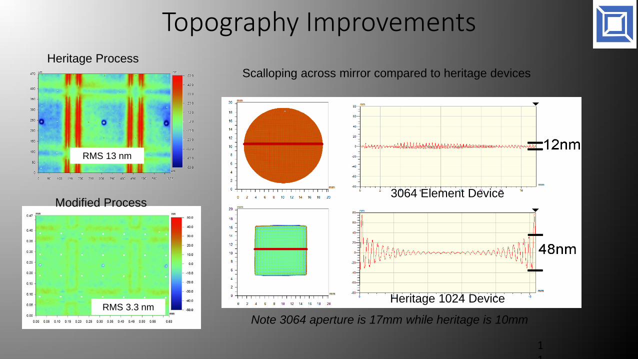
Topography Improvements
11
Modified Process
Heritage Process
RMS 13 nm
RMS 3.3 nm
Scalloping across mirror compared to heritage devices
3064 Element Device
Heritage 1024 Device
Note 3064 aperture is 17mm while heritage is 10mm

Topography Improvements
FilteredUnpowered Surface With low order filtered
(control bandwidth)
<7nm RMS<1um P-V
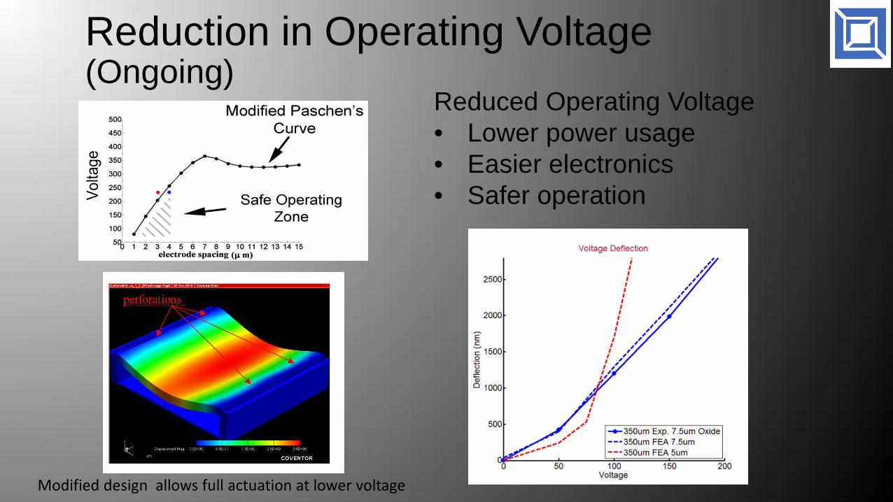
Reduction in Operating Voltage (Ongoing)
Reduced Operating Voltage• Lower power usage• Easier electronics• Safer operation
Modified design allows full actuation at lower voltage

Enhanced Reliability Concept
Deflection versus voltage. Initial, after cycling 3 million times above critical voltage (295V).
Enhanced ReliabilityActuator Design
V > Vcritical V > Vcritical
EOS DAMAGE
“Hard Stops”
Outline• BMC DM Technology• Mirror technology programs• Space qualification programs• DMs in telescopes
• Ground• Space
• Next steps for scaling DM actuator count
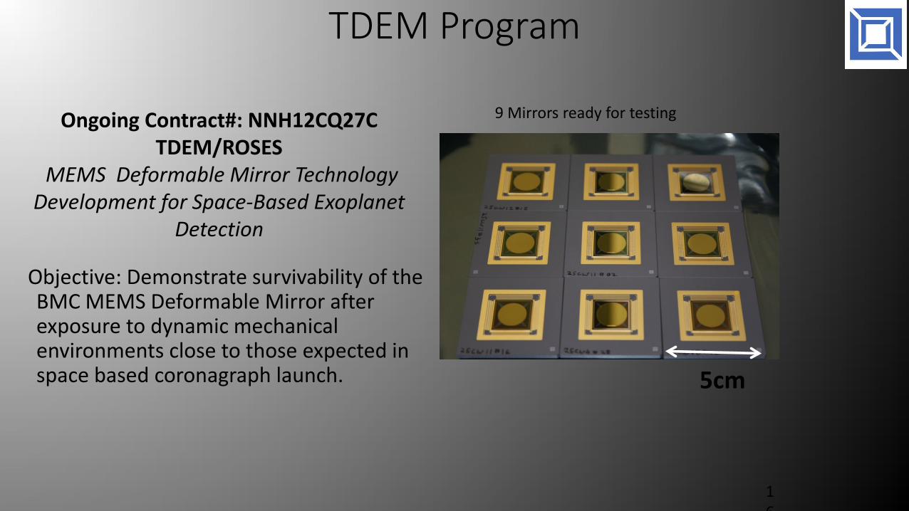
TDEM Program
16
Ongoing Contract#: NNH12CQ27CTDEM/ROSES
MEMS Deformable Mirror Technology Development for Space-Based Exoplanet
Detection
5cm
Objective: Demonstrate survivability of the BMC MEMS Deformable Mirror after exposure to dynamic mechanical environments close to those expected in space based coronagraph launch.
9 Mirrors ready for testing
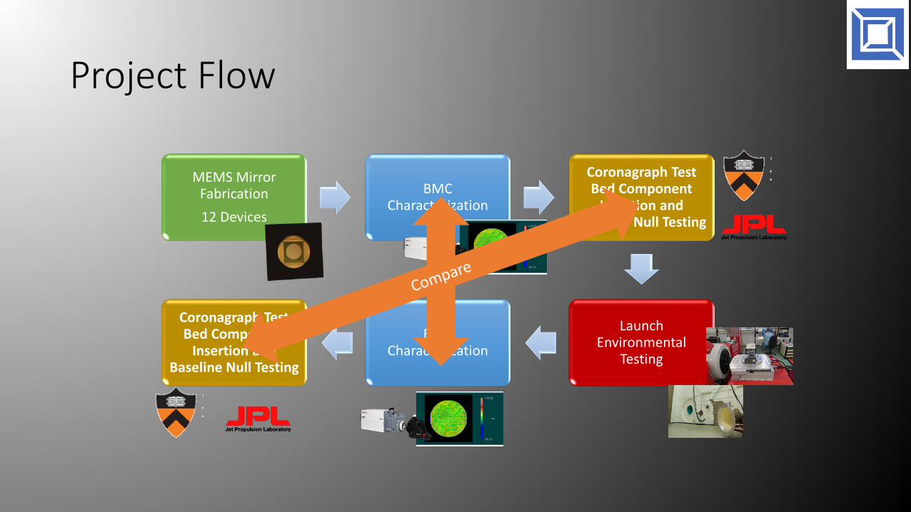
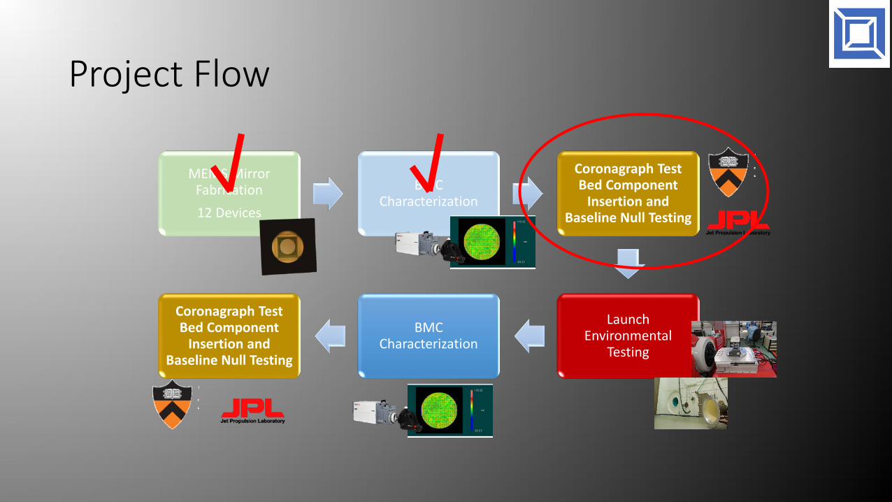
Project Flow
MEMS Mirror Fabrication12 Devices
BMC Characterization
Coronagraph Test Bed Component
Insertion and Baseline Null Testing
Launch Environmental
Testing
BMC Characterization
Coronagraph Test Bed Component
Insertion and Baseline Null Testing

12 DMs Fabricated and Characterized
Rq = 5.3 nm
Voltage v. Deflection
Single Actuator Surface FigureRq = 6.14 nm
Active Flattening of DM Surface
Sinusoid Shape4 Period, 400nm Amplitude
Delivered to JPL (2) and Princeton (2)
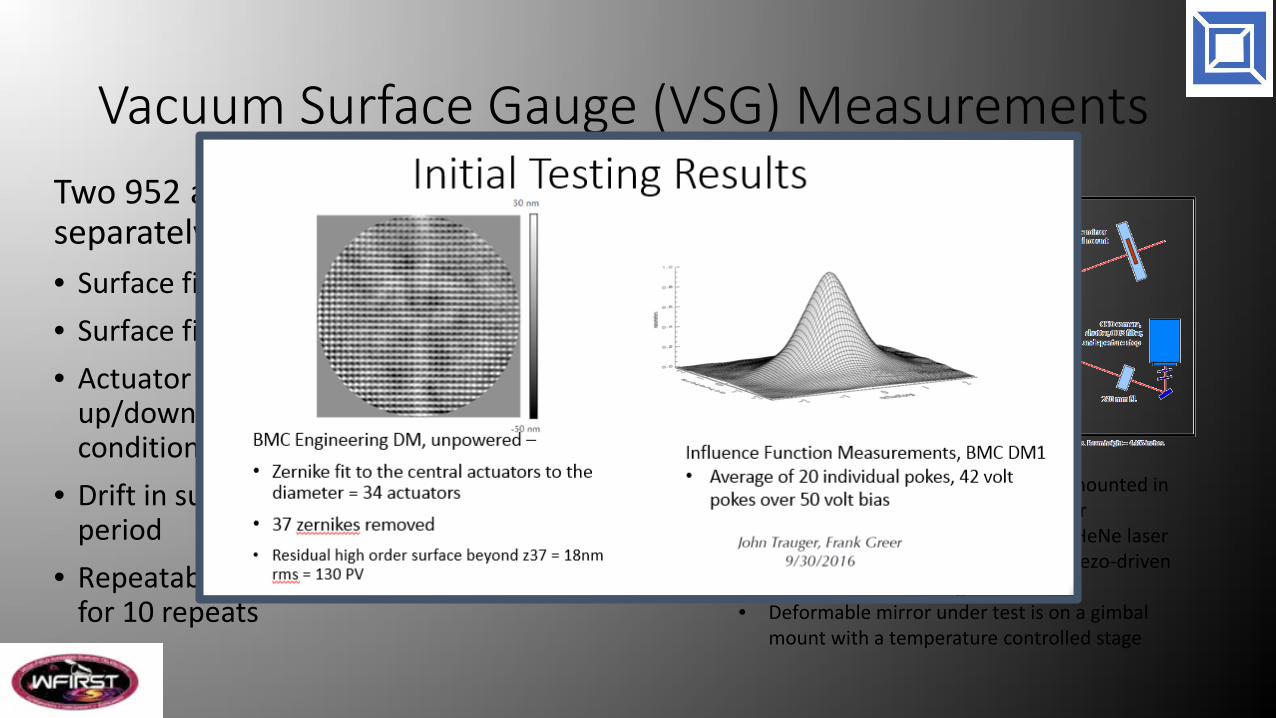
Vacuum Surface Gauge (VSG) MeasurementsTwo 952 actuator MEMS DMs (tested separately)• Surface figure of DM at zero bias• Surface figure of DM for flat surface• Actuator gains for all 952 actuators for small
up/down pokes about the flat surface condition
• Drift in surface for “flat” condition for 48 hour period
• Repeatability from “flat” and BMC/JPL solution for 10 repeats
• VSG is a Michelson interferometer mounted in a vibration isolated vacuum chamber
• Light source is 632.8 nm frequency HeNe laser• Reference mirror is mounted on a piezo-driven
flexure translation stage• Deformable mirror under test is on a gimbal
mount with a temperature controlled stage
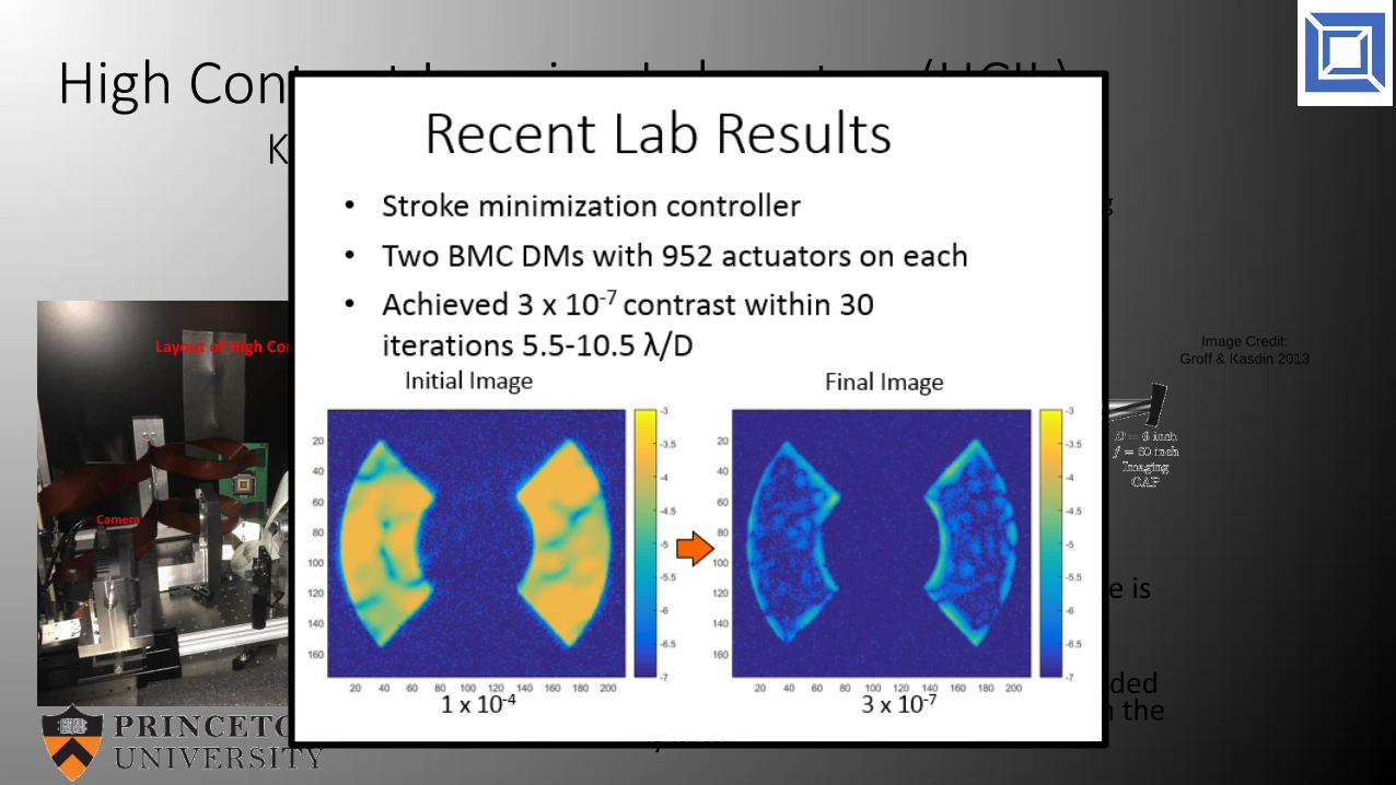
• Shaped pupil coronagraph technique is used to achieve high contrast for exoplanet direct imaging.
• 2 BMC deformable mirrors are included to compensate optical aberrations in the system.
Image Credit:Groff & Kasdin 2013
High Contrast Imaging Laboratory(HCIL)Kasdin Lab, Princeton University
Focal Plane Wavefront Correction (FPWC) for Exoplanet Coronagraph Imaging
Project Flow
MEMS Mirror Fabrication12 Devices
BMC Characterization
Coronagraph Test Bed Component
Insertion and Baseline Null Testing
Launch Environmental
Testing
BMC Characterization
Coronagraph Test Bed Component
Insertion and Baseline Null Testing

Outline• BMC DM Technology• Mirror technology programs• Space qualification programs• DMs in telescopes
• Ground• Space
• Next steps for scaling DM actuator count
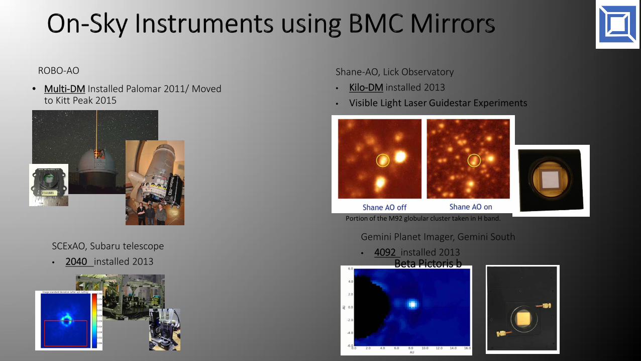
ROBO-AO
• Multi-DM Installed Palomar 2011/ Moved to Kitt Peak 2015
Shane-AO, Lick Observatory• Kilo-DM installed 2013• Visible Light Laser Guidestar Experiments
Portion of the M92 globular cluster taken in H band.
Beta Pictoris b
Gemini Planet Imager, Gemini South• 4092 installed 2013SCExAO, Subaru telescope
• 2040 installed 2013
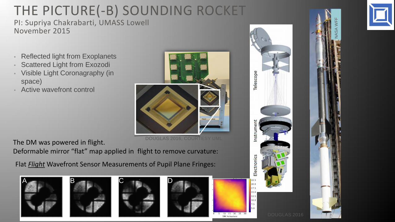
• Reflected light from Exoplanets• Scattered Light from Exozodi• Visible Light Coronagraphy (in
space)• Active wavefront control
NA
SA
WFF
DOUGLAS 2016
DOUGLAS 2016, COURTESY UML
THE PICTURE(-B) SOUNDING ROCKETPI: Supriya Chakrabarti, UMASS LowellNovember 2015
A B C D
The DM was powered in flight. Deformable mirror “flat” map applied in flight to remove curvature:
Flat Flight Wavefront Sensor Measurements of Pupil Plane Fringes:

Cubesat: Deformable Mirror Demonstration Mission (DeMi) PI: John Merk, Aurora Flight Systems, Keri Kahoy, MIT
• Validate and demonstrate the capabilities of high actuator count MEMS deformable mirrors for high contrast astronomical imaging.
• Characterize MEMS deformable mirror operation using both a Shack Hartmann wavefront sensor as well as sensorless wavefront control.
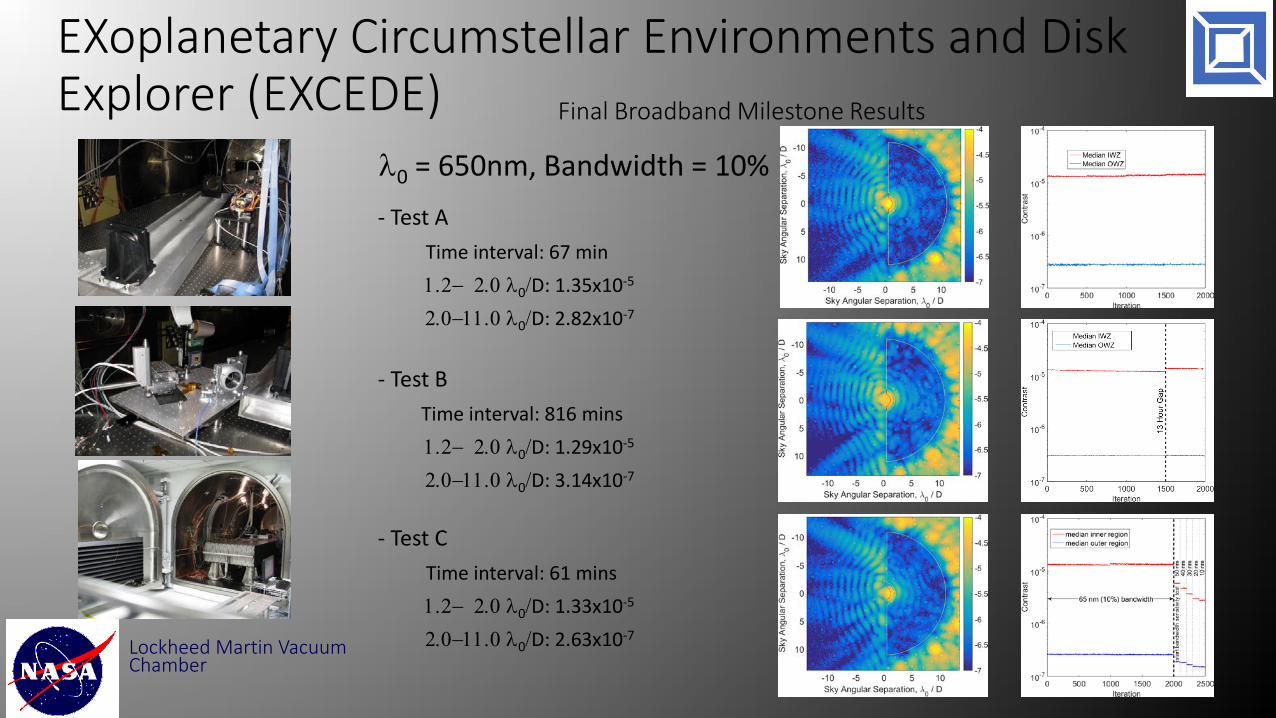
EXoplanetary Circumstellar Environments and Disk Explorer (EXCEDE)
Lockheed Martin Vacuum Chamber
λ0 = 650nm, Bandwidth = 10%- Test A
Time interval: 67 min1.2− 2.0 λ0/D: 1.35x10⁻⁵
2.0−11.0 λ0/D: 2.82x10⁻⁷
- Test BTime interval: 816 mins1.2− 2.0 λ0/D: 1.29x10⁻⁵
2.0−11.0 λ0/D: 3.14x10⁻⁷
- Test CTime interval: 61 mins1.2− 2.0 λ0/D: 1.33x10⁻⁵
2.0−11.0 λ0/D: 2.63x10⁻⁷
Final Broadband Milestone Results

EXCEDE Proposing for the 2016 MidEX AO- Technical specs:
- 0.7m primary, TMA unobstructed optical telescope- PIAA Coronagraph
- Mission overview - Survey of ~ 350 nearby exoplanetary systems
- Science Capabilities- Circumstellar debris systems including the habitable zone- Gas giants (if sufficiently bright)
1K Boston MEMS DMOuter Working Angle – 15 L/D
3K-C Boston MEMS DMOuter Working Angle – 31 L/D
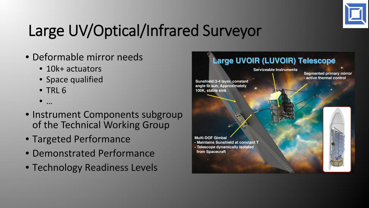
Large UV/Optical/Infrared Surveyor• Deformable mirror needs
• 10k+ actuators• Space qualified• TRL 6• …
• Instrument Components subgroup of the Technical Working Group
• Targeted Performance• Demonstrated Performance• Technology Readiness Levels

Outline• BMC DM Technology• Mirror technology programs• Space qualification programs• DMs in telescopes
• Ground• Space
• Next steps for scaling DM actuator count

Need for Even Higher Actuator Count DM (10k +)
• For many next generation instruments, more actuators are needed
• Limited by electrical interconnects• Wirebond for each actuator• Span of active optical surface scales with N• Span of the chip scales with N2
• Limits number of die on a wafer• Increases the likely hood of a single point defect
causing short/failure
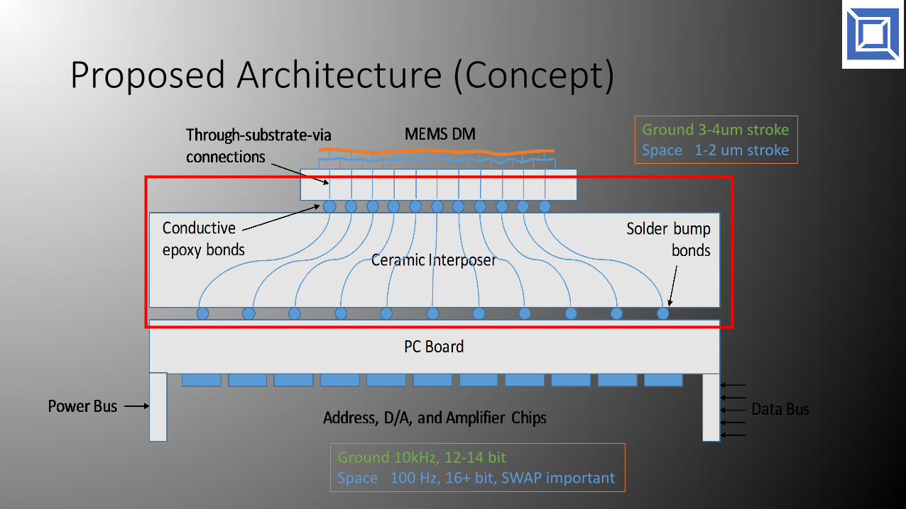
Proposed Architecture (Concept)Ground 3-4um strokeSpace 1-2 um stroke
Ground 10kHz, 12-14 bitSpace 100 Hz, 16+ bit, SWAP important
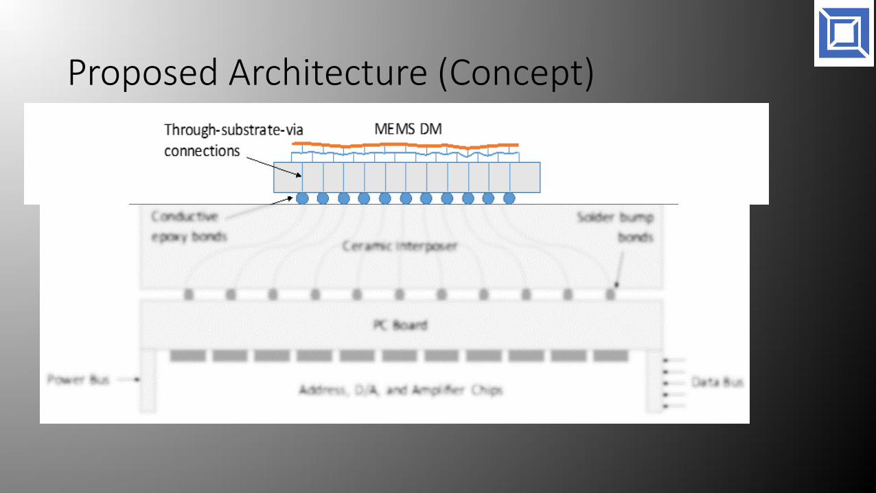
Proposed Architecture (Concept)

Through-Wafer-Via DM Fabrication Prototype
New process (and new foundry for manufacturing) relies on BMC heritage actuator and mirror design, but eliminates wire bonds and instead uses through-wafer-via (TWV) technology
TWV is single crystal silicon: exceptionally low defect level allows major increase in device yield and reliability
Manufacturing challenge is shifted to packaging of TWV devices
In prototype project, 140 actuator, 500 actuator, and 2000 actuator devices were fabricated and tested
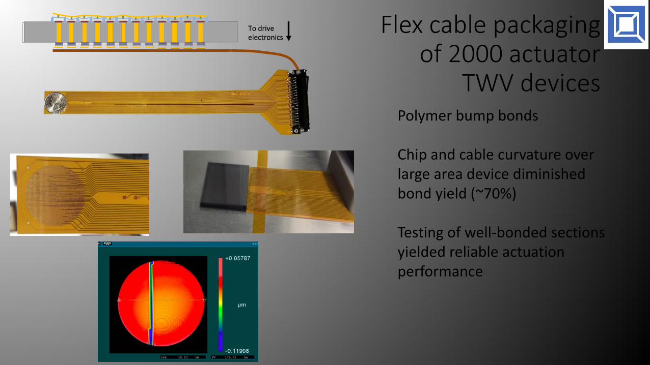
Flex cable packaging of 2000 actuator
TWV devices Polymer bump bonds
Chip and cable curvature over large area device diminished bond yield (~70%)
Testing of well-bonded sections yielded reliable actuation performance
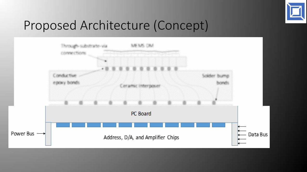
Proposed Architecture (Concept)

Electronics Design
•The controller has a volume of 90mm (w) x 90mm (l) x 54.6mm (h), w/o mirror and socket.•It only requires a 12V power supply and consumes 6W.•USB interface for data•0-215V, 16 bits•Scalable technology for greater channel count
Conclusion
• MEMS DM have been proven in astronomical instrumentation
• Continued technology development is ongoing
• Poised for next generation instruments, but development needs to occur.