closed-loop control of gimbal-less mems mirrors for ...mirrorcletech.com/pdf/press/mirrorcletech -...
TRANSCRIPT
Presented at SPIE Conference on Laser Radar Technology and Applications XXII, Anaheim, CA Apr. 12th, 2017.
*[email protected] Phone: +1-510-524-8820 www.mirrorcletech.com
Closed-Loop Control of Gimbal-less MEMS Mirrors for Increased
Bandwidth in LiDAR Applications
Veljko Milanović*, Abhishek Kasturi, James Yang, Frank Hu
Mirrorcle Technologies, Inc., 4905 Central Ave, Richmond, CA 94804
ABSTRACT
In 2016, we presented a low SWaP wirelessly controlled MEMS mirror-based LiDAR prototype which utilized an OEM
laser rangefinder for distance measurement [1]. The MEMS mirror was run in open loop based on its exceptionally fast
design and high repeatability performance. However, to further extend the bandwidth and incorporate necessary eye-
safety features, we recently focused on providing mirror position feedback and running the system in closed loop control.
Multiple configurations of optical position sensors, mounted on both the front- and the back-side of the MEMS mirror,
have been developed and will be presented. In all cases, they include a light source (LED or laser) and a 2D photosensor.
The most compact version is mounted on the backside of the MEMS mirror ceramic package and can “view” the
mirror‟s backside through openings in the mirror‟s PCB and its ceramic carrier. This version increases the overall size of
the MEMS mirror submodule from ~12mm x 12mm x 4mm to ~15mm x 15mm x 7mm. The sensors also include optical
and electronic filtering to reduce effects of any interference from the application laser illumination.
With relatively simple FPGA-based PID control running at the sample rate of 100 kHz, we could configure the overall
response of the system to fully utilize the MEMS mirror‟s native bandwidth which extends well beyond its first
resonance. When compared to the simple open loop method of suppressing overshoot and ringing which significantly
limits bandwidth utilization, running the mirrors in closed loop control increased the bandwidth to nearly 3.7 times. A
2.0mm diameter integrated MEMS mirror with a resonant frequency of 1300 Hz was limited to 500Hz bandwidth in open loop driving but was increased to ~3kHz bandwidth with the closed loop controller. With that bandwidth it is
capable of very sharply defined uniform-velocity scans (sawtooth or triangle waveforms) which are highly desired in
scanned mirror LiDAR systems. A 2.4mm diameter mirror with +/-12° of scan angle achieves over 1.3kHz of flat
response, allowing sharp triangle waveforms even at 300Hz (600 uniform velocity lines per second). The same
methodology is demonstrated with larger, bonded mirrors. Here closed loop control is more challenging due to the
additional resonance and a more complex system dynamic. Nevertheless, results are similar - a 5mm diameter mirror
bandwidth was increased from ~150Hz to ~500Hz.
Keywords: MEMS mirrors, closed loop, laser tracking, laser imaging, laser range finder, UAV, LiDAR, scanned LiDAR.
1. INTRODUCTION
1.1 LIDAR Background
Development of LiDAR technology and its applications has recently been accelerated by the optical sensing needs in
advanced driver assistance systems (ADAS) and autonomous navigation of ground and air vehicle systems [2][3]. A
variety of approaches and technologies have been under development to obtain the best cost, size, and performance for
various specific requirement cases. Most scanning LiDAR architectures rely on the beam steering capabilities of MEMS
mirrors to obtain the necessary scanning over a required field of regard (FoR). For example, researchers at the Army
Research Laboratory (ARL) have utilized Mirrorcle Technologies gimbal-less dual-axis MEMS mirrors for their laser
beam steering based LiDAR development for robotic vision and other defense applications [4]. A Boeing Spectrolab
scanning LiDAR product, SpectroScan 3D also employs the same MEMS mirrors in its transmitter section (Figure 1b).
In a simplified form, LiDAR systems consists of a pulsed light source with beam steering ability, a low noise and high gain optical receiver, and a digital circuit to calculate the amount of time between the light pulse leaving the system and
the reflected photons from the light pulse returning to the receiver. The time difference can be used with the speed of
light constant (~3 x 10⁸ m/s) to calculate the distance travelled by the light pulse. So e.g. a 20ns time in between the
outgoing and returning pulse means 20 x 10-9s * 3 x 108 m/s = 6m. In order to obtain distances to many points in different
directions from the source and generate 3D point clouds in a specific field-of-regard (FoR), a laser beam steering system
is used to scan the outgoing pulses over the FoR. The receiver, depending on the specific system architecture, may be
aimed in the same direction, de-scanned by the same beam-steering system, or it may have its receiving optics expanded
to continuously view the full FoR. The laser pulsing, pulse receiving, and ranging (ToF measurement) subsystems of the

Presented at SPIE Conference on Laser Radar Technology and Applications XXII, Anaheim, CA Apr. 12th, 2017.
*[email protected] Phone: +1-510-524-8820 www.mirrorcletech.com
LiDAR, although in some cases challenging, are well established technologies and quite well understood. However, the
beam steering subsystem is a key developing technology to enable most sought-after applications. Achieving the
compact size and low weight, achieving high speed of scanning over a large 2D FoR, and reducing system cost and
power consumption can all be largely dependent on this subsystem. Here, the key component is the laser beam steering
MEMS mirror and its controller. At this time, the industry views this technology as the key enabler for those
performance and cost milestones to enable the applications.
Figure 1. MEMS mirror based scanning LiDAR systems: a) MEMS mirrors of 1.2mm diameter (A3I12.2-1200AL) packaged in 9mm x 9mm wide ceramic carrier in connectorized PCBA form for easy mounting in prototype Scan Modules, b) MEMS LIDAR SYSTEM “SpectroScan 3D” from Boeing Spectrolab [10], c) Lead author is testing a similar MEMS LiDAR system developed at NASA Goddard [15].
1.2 Prior Work
The above cited ARL LiDAR project originally published ranging of up to 35m within a 40° x 20° FoR at up to 6 Hz
frame rate [4]. The design used a gimbal-less, dual-axis, 1.2mm diameter MEMS mirror, a wide angle (projection) lens
for transmitting the pulsed laser beam, and a separate aperture for receiving the reflected light. This kind of a duostatic
LiDAR design is very well suited for MEMS mirrors which typically have small optical apertures (diameters). Namely, a
very small and therefore very fast, robust, and low cost MEMS mirror can easily meet the requirements for a LiDAR
transmitter. For example, with a 2mm diameter mirror and wide angle projection optics, a beam divergence of <0.1° can
be achieved which meets most application requirements. However, receivers greatly benefit from larger aperture sizes of
up to e.g. 25mm and having a separate receiver that is not aperture limited by the MEMS mirror is generally beneficial.
In their updated publication [4], ARL demonstrated ranging up to 160m using the same transmitter with improved receiver electronics and optics to increase the signal-to-noise ratio (SNR). They also demonstrated mirror position
sensing features for eye-safety requirements of their application. There are also successful monostatic architectures with
MEMS mirrors which utilize mirrors of larger diameter in order to have a larger effective receiving aperture.
Previously, we demonstrated the capability of MEMS-based LiDAR for minimal weight, size, and power consumption in
a prototype ranging system [1]. The system was attached beneath a lightweight quadcopter and flown in indoor
demonstrations of scanning, tracking, and ranging. It includes a MEMS Scan Module, controller with wireless
communication, and a photosensor-receiver all powered from the quadcopter‟s battery. The overall weight of the Scan
Module with the controller was as low as 50g in the tracking/imaging function. The version which includes an OEM
laser rangefinder to add distance ranging capability weighs approximately 140g. The volume of the system can be
contained within 70 mm x 60 mm x 60 mm. The total power consumption, including the MEMS actuator, laser, and
controller is less than 1 W. This scanning system used a 1.2 mm diameter MEMS mirror in a dual aperture system where
the MEMS mirror is not the limiting factor and can be reduced in size to increase the scanning bandwidth.
2. SCAN MODULES FOR MEMS BASED LIDAR
2.1 Gimbal-less MEMS mirrors overview
Gimbal-less MEMS mirrors are capable of running in quasi-static mode with a wide bandwidth capability, allowing
different scanning modes. A Scan Module with laser(s), optics, and the MEMS mirror is able to scan and deliver laser
pulses over its entire field of regard in a variety of programmable ways. A simple and typical use may be to scan over the
FoR in a line by line raster fashion with a fast retrace from the end of the scan back to the initial point of the first line. In this case, users may desire that lines are scanned with uniform beam velocity in order to achieve equal distance and
(a) (b) (c)

Presented at SPIE Conference on Laser Radar Technology and Applications XXII, Anaheim, CA Apr. 12th, 2017.
*[email protected] Phone: +1-510-524-8820 www.mirrorcletech.com
timing between imaged or displayed pixels. To achieve this flexibility and reconfigurability, the device is designed with
point-to-point or quasi-static two-axis beam steering capability with a large mechanical tip/tilt angle and a high
frequency response bandwidth. The MEMS mirrors are based on monolithic, vertical combdrive actuators. The gimbal-
less design results in fastest two-axis beam steering with large mechanical deflections over the entire device bandwidth,
e.g. from DC to a >2 kHz for 2mm diameter mirror size [5]. The capability for equally fast beam steering in both axes is
a great match for use in laser imaging and tracking [9], laser marking, and 3D printing applications as well as present work for scanning LiDAR.
Figure 2. Gimbal-less dual-axis MEMS mirror examples: a) The A7M20.1 2mm diameter mirror in a TINY20.3 connectorized package, b) A 3mm diameter mirror in TINY20.3 connectorized package with an anti-reflection aperture to reduce spurious reflections c) A 5mm diameter mirror in DIP24 package d) A custom flex-PCB package that holds a 7.5mm diameter mirror.
The MEMS mirror device (Figure 2) is made entirely of monolithic single-crystal silicon, resulting in excellent
repeatability and reliability. Flat, smooth mirror surfaces are coated with a thin film of aluminum with high broadband
reflectance in a wide range of wavelengths. Flatness of the final, metalized and packaged mirrors is tested on a Bruker
Contour GL interferometer. Most mirrors measure above 7-8m radius of curvature which is typically independent of
mirror diameter. With such high flatness and surface roughness below 5 nm, the mirrors are highly suitable for LiDAR
application and capable of high quality (pulsed) beam delivery to targets at >100 of meters distance. Another important
benefit of electrostatic driving and pure single-crystal silicon construction is an exceptionally wide range of operation
temperature. We have demonstrated normal operation at up to 200 °C, while a research group at Stanford University has
utilized the same devices at temperatures below -200 °C without any noted degradation in performance [6][7].
As mentioned above, the design is focused on wide bandwidth to allow the laser beam scan to directly follow arbitrary
voltage commands on a point-to-point basis. A fast sequence of actuation voltages results in a fast sequence of angles for
point-to-point scanning. There is a one-to-one correspondence of actuation voltages and resulting angles: it is highly
repeatable with no detectable degradation over time. For devices with mechanical tilt range of -5° to +5° on each axis,
tilt resolution (repeatability of steering to a specific angle over an extended period of time) is within 0.6 milli-degrees or
within approximately 10 micro-radians [16].
To actuate the rotating bi-directional electrostatic combdrives, we utilize a “push-pull” method of driving with a Bias-
Differential Quad-channel (BDQ) scheme [8]. This scheme linearizes actuators‟ voltage-angle relationship and improves
smooth transitions from one quadrant to another, i.e. from one actuator to another within the device. In this mode, both
the positive rotation portion and the negative rotation portion of each rotator are always differentially engaged.
Specifically, we bias all of the moving sections of the combdrives with 80V with respect to stators. Then, in response to
user commands for mirror tilt, one section is given additional voltage and the opposite-acting section reduced voltage. Driving the MEMS mirror to full tip/tilt angles on both axes (4-quadrants) therefore utilizes four high voltage channels
with 0 to ~160V output range.
2.2 Reconfigurable Scanning using Mirrorcle’s MEMS Technology
As mentioned in the previous section, having a two-axis gimbal-less MEMS mirror with quasi-static (point-to-point)
capability and a very wide bandwidth allows for very flexible beam steering and therefore flexible imaging or LiDAR
point-cloud acquisition. The number of lines, pixels along a line and the scan area can be arbitrarily programmed and
controlled [9]. The ultimate limit is based on the optical resolution considerations of the transmitted beam, i.e.
considering how small of an area in a target field of view the beam can address. For the highest “zoom-in” capability it
would be ideal to have this area as small as possible, i.e. a laser beam of lowest divergence. However, there are cases
where the opposite would be useful as well, e.g. to obtain quick preview scans of a wide field of view with few lines and
pixels – here a large beam divergence would work best to fully cover the region with less lines, however, it would trade
5mm Mirror 7.5mm Mirror3mm Mirror
(a) (b) (c) (d)
2mm Mirror
Presented at SPIE Conference on Laser Radar Technology and Applications XXII, Anaheim, CA Apr. 12th, 2017.
*[email protected] Phone: +1-510-524-8820 www.mirrorcletech.com
off power density. For this capability, we have been investigating adaptations of our Scan Modules to include a
controllable-focus electro-optic lens providing on-demand divergence control.
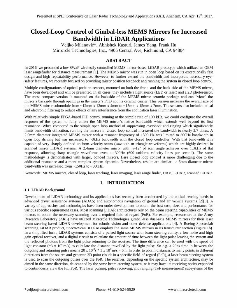
Figure 3. Examples of reconfigurable scanning using Mirrorcle MEMS mirrors: a) Example of a raster scan with 48 lines, scanning
at 52 Hz, over a 12° x 12° area, b) The same resolution of the scan, with 48 lines updating at 52 Hz refresh rate is offset to +20° on X-axis and +20° on Y-axis, and scanning a FoV of +/-6°, c) An example of a raster scan in a typical LiDAR application with a wide FoV of 60° on X-Axis and a narrow FoV of +/-10° on Y-Axis.
With a line time of e.g. 0.0005s, scanning 20 lines results in 100Hz refresh rate while scanning of 200 lines results in 10
Hz. Although quasistatic-capable mirrors have relatively lower resonant frequencies, there are still many designs with
>5kline/s rates. In this case with 0.0002s per line, measuring 25 lines is possible at 200Hz. In the examples shown in
Figure 3a, b, the MEMS mirror scans a 12° x 12° field of regard with 48 lines, and a refresh rate of 52Hz. The same
number of lines and refresh rate is then offset and scanned over a smaller area of approximately 9° x 9°, increasing the density of the points sampled in the given area. Figure 3c demonstrates the ability of the MEMS mirror to perform the
scan of a typical LiDAR application requirement of a 60° by +/-10° FoV, which can be used as a segment in a set of 3, to
observe a full 180° FoV.
The MEMS mirror can address the entire field of regard, or any sub-region within the field of regard, with an arbitrary
number of lines, offset and orientation of the line scan. This quasi-static mode of driving of the MEMS mirror can be
combined with the single-pixel camera sensor to image the field of regard, zoom in to any areas, and even track targets
within areas of the FoR by adjusting the offset of the raster scan at each pass [9]. The scanner can continue tracking the
target as it moves anywhere within the overall field of regard of the LiDAR.
2.3 Silicon as a Most Reliable Platform for MEMS Scanning LiDAR
Our complete MEMS mirror device is fabricated from single-crystal silicon, the best possible material for such miniature
flexing mechanical designs. It has nearly perfect elastic properties and has no long-term degradation, plastic deformation.
Is is superior in long-term stability and repeatability compared to polysilicon and other „MEMS‟ materials. Single crystal silicon is a fully elastic material, and has nearly perfect characteristics for use in smaller (mm and µm) dimensions. As a
single crystal silicon flexure undergoes deformation, the internal stress increases, but as the force causing the
deformation is removed, the material returns elastically to its undeformed state. Should the strain be increased such that
the stress exceeds a critical level, brittle fracture will occur. Simply put, a single crystal silicon flexure has no known
mechanisms of long term degradation like metals or plastic materials, or even polysilicon.
High-aspect ratio SOI MEMS structures used in our devices are highly resistant to shock and vibration interference, and
low inertia mirror design results in overall tiny masses which further contribute to such robustness. Multiple batches of
our devices have already passed 500G shock tests at a third-party facility, 20G vibration tests from 20Hz to 2000Hz, and
temperature cycling tests from -45° to +125°C [12]. We have demonstrated operation at temperatures as high as 200°C.
Given the shock, vibration, and temperature requirements of automotive sensing platforms, Mirrorcle‟s MEMS
technology offers a robust, highly viable solution for scanning LiDAR.
2.4 Addressing a Wide FoR
In order to address a wide FoR for the LiDAR application, it is useful to increase the field of view of the MEMS Scan
Module. Since the native optical scanning angle of the 2mm MEMS mirror is -10° to +10°, we employed a wide angle
lens design [9][14] to increase the overall field of view to over 48° with one design and to 70° with a more aggressive
design. In this improved methodology we reduced the number of optical elements by inserting the MEMS mirror into the
middle of the wide angle objective lens set. Namely as seen in Figure 4, the MEMS mirror is placed in between the
20
20 -20
20
20 -20
20
20 -20
48 lines, 52 Hz
12 x 12
48 lines, 52 Hz
6 x 6
110 lines, 100 Hz
60 x 20
(a) (b) (c)
Presented at SPIE Conference on Laser Radar Technology and Applications XXII, Anaheim, CA Apr. 12th, 2017.
*[email protected] Phone: +1-510-524-8820 www.mirrorcletech.com
positive lens element and the negative lens element which together form the beam-reducer that increases the scan angle
by approximately 2.4X. Finally, the complete optical cell can be reduced in size and formed out of simple spherical off-
the-shelf lens elements as seen in Figure 4c, and held in place by a machined or 3D printed cell housing.
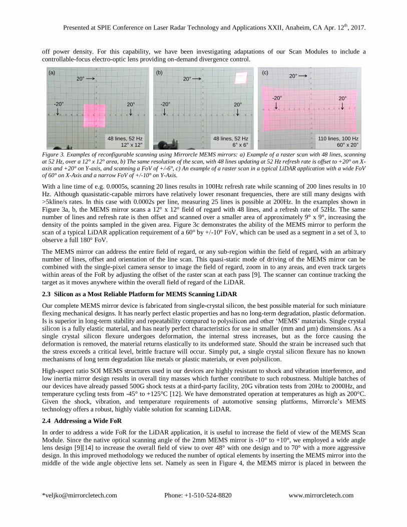
The 48° scanning capability comes with inherent pin-cushion distortion. In addition to that, any misalignment of the
optics and the MEMS mirror as well as some F-Theta nonlinearity results in a non-ideal scan field of the light engine. As
we see from the device‟s static response in Figure 4b, there is nonlinearity at larger angles in the device as well adding to the complexity of the final relationship between input commands and output beam location. Here we find another major
advantage of vector graphics methodology, namely that it allows us to practically eliminate all of these distortions by
allowing the user to fully control the beam position and velocity and therefore to correct any amount of optical field
distortion either computationally by model or by actual measurement/calibration [7]. We have successfully demonstrated
correction of major non-linearities in the projection lens, MEMS device, as well as correction of perspective angles when
projecting content onto non-normal surfaces in the past, and have integrated these correction capabilities into our light
engine control software. Ultimately, a complete unit-specific look up table can be created during production/calibration
that fully eliminates beam pointing errors.
An example of the expansion of FoR using expansion optics is shown in the center and right side of Figure 4.
Additionally, the lower cost and compactness of MEMS mirror based transmitter can allow a segmented design – e.g.
breaking the range into three panes allows for the center pane to view straight down the road to more clearly see
oncoming objects without any potential issues that may arise from having a seam down the center of the forward view. Similarly, 5 panes would allow for an unimpeded forward view, but have the increased cost and complexity of more
optics, mirrors, and supporting electronics. Scanning the FoR with a single lens and mirror will be investigated, however,
this may only be possible with suboptimal lateral resolution, given the high angular expansion of the optics.
Figure 4. a) Methodology of raster scanning a laser beam over a field of regard with uniform-velocity lines in both forward and backward direction, with narrow turn-around sections which requires a beam-steering system with a broadband triangle waveform
capability, b) a scan of a 24 FoR without wide-angle projection optics; c) A scan of a 75 FoR using the same MEMS mirror and a
wide-angle projection lens with 2 spherical elements.
2.5 Scanning Requirements for LIDAR
Based on the information presented in the above sections and feedback from various applications of LiDAR in the
automotive, scientific, and commercial industries, an advanced scanning LiDAR system would have the following
capabilities:
Control of the scanning resolution and refresh rate of the scanner to arbitrarily address any field of view within the scanner‟s capabilities. In other words, reconfigurability.
Ability to scan uniform velocity waveforms such as Sawtooth (uni-directional uniform velocity scans) or
Triangle waveforms (bi-directional uniform velocity scans).
Ability for fast point to point steps, at least on the “vertical axis” to adjust the vertical position of each scanned
line.
A very wide bandwidth on both axes to address a higher resolution field of view or for fast refresh rates.
Bandwidth of at least 1kHz would apply to most applications and >2kHz would allow very flexible and
advanced designs.
A large enough aperture to scan the infrared pulsed beam over the field of regard with a relatively small
divergence of <=0.1°.
Full Scan FoV
Active Scan FoV
Turn Around Time Turn Around Time
Forward Scan Backward Scan
24 Optical Scan 75 Optical Scan
3x Wide Angle Lens
(a) (b) (c)

Presented at SPIE Conference on Laser Radar Technology and Applications XXII, Anaheim, CA Apr. 12th, 2017.
*[email protected] Phone: +1-510-524-8820 www.mirrorcletech.com
A small MEMS mirror such as the 1.2mm can already scan a pulsed beam over the FoR, and has been demonstrated by
the Boeing Spectrolab scanning LiDAR [10]. As shown in Figure 3, a MEMS mirror scanning system can already
demonstrate arbitrary control of the number of lines, resolution, refresh and addressable field of view. However, the
small mirror diameter corresponds to larger divergence and may not apply as well to longer distances or in conjunction
with wide FoR scanning optics. Additionally, a smaller diameter mirror would have a correspondingly lower limit on
optical power, both in terms of the average power (heating) and pulse power (power density on the thin film). On the other hand their very high speed capability with over 3.5kHz of -3dB response bandwidth is highly attractive in very fast
refresh rate applications in shorter distances such as e.g. for UAV (drone) collision avoidance LiDAR and robot vision
systems [2],[4],[15].
To address small divergence requirements, especially with wide angle projection optics, a larger mirror is highly
advantageous. Here the 2.0mm diameter MEMS mirror A7M20.1 is a great match. This device can address the same +/-
10° FoR without projection optics and with a divergence below 0.025° (~0.5mrad) at 905nm. Even with wide angle
projection optics giving a FoR as high as +/-37.5° (Figure 4c) a Scan Module with this mirror could maintain divergence
of <=0.1° (2mrad). This 2mm MEMS mirror can also work with more powerful lasers, especially where the high
repetition rates result in higher average power. In another application with blue lasers we operate with CW power of over
4W without any degradation or damage which can be extended with specialized heat-removing packaging to a much
higher value [17]. The 2.0mm mirror, however, has 2kHz of -3dB response bandwidth which is naturally lower than that
of the 1.2mm mentioned above. However, if this bandwidth can be fully utilized as we explore in the following section, such performance can cover a wide range of very demanding LiDAR applications.
In the following section we focus on a number of methodologies to control these MEMS mirrors to achieve desired scan
waveforms for LiDAR applications. Specifically we focus on methodologies to utilize as much device bandwidth as
possible both in open-loop and closed loop driving without exciting resonant (ringing or oscillating) response.
3. OPEN LOOP METHODOLOGIES TO INCREASE BANDWIDTH
3.1 Driving with Low Pass Filter
Figure 5. a) Magnitude of the frequency response of the 2mm diameter MEMS mirror (A7M20.1) and the 600 Hz low-pass filter which
is used to limit the response near the resonant frequency and b) overall response (magnitude) of a Scan Module with the MEMS mirror controlled in open-loop (feed-forward) control with the LPF, the -3dB point is approximately at 500Hz, c) 100 Hz triangle waveforms scanned by the device with the bandwidth shown in (b).
The simplest form of controlling the MEMS device‟s bandwidth and response is by implementing a low-pass filter in
series with the drive signal. The components can be as simple as passive resistor and capacitor components, more
complex filters like programmable switched-capacitor filters, or op-amp based continuous time filters at a fixed cut-off
bandwidth. In order to have a wider useable bandwidth and sufficient suppression of the high quality factor resonance, a
higher order Bessel filter (5th or 6th order) is recommended, which may require a lot of components. However, as it is the
simplest method to implement with minimal risk on damaging the device or exceeding its maximum mechanical angle, low-pass filtering (Figure 5a) is used in most open loop applications with MEMS mirrors. The result is very reliable
driving with practically no overshoot or ringing and very unlikely damage from unconditioned input waveforms. Figure
5 shows an example with the A7M20.1 MEMS mirror with a 2mm diameter mirror. In Figure 5a, we see the frequency
response of the mirror which is nearly identical for both axes due to the symmetric gimbal-less design (red and blue
Frequency (Hz)
Response M
agnitude (
norm
)
(a) (b) (c)
LPF Filter BW = 600Hz
Time (s)
Mech. A
ngle
(deg)
100 Hz Triangle Waveform

Presented at SPIE Conference on Laser Radar Technology and Applications XXII, Anaheim, CA Apr. 12th, 2017.
*[email protected] Phone: +1-510-524-8820 www.mirrorcletech.com
curve). The response has a high Q resonance of approximately 70 [12]. The Bessel filter response is also shown
approximately with the blue dashed lines. In Figure 5b, we show the measured overall frequency response of the
A7M20.1 MEMS device when driven with the 600 Hz low pass filtered waveforms. This bandwidth limited MEMS
device is able to scan 100 Hz triangle waveforms with relatively linear line scans but take a significant portion of time
and angle in the turning regions (Figure 5c).
3.2 MEMS Driving with Inverse System Filter
Another method of open loop or feed-forward driving that is more complex but allows additional utilization of
bandwidth requires an approximate inverse system of the MEMS model to act as a filter [11]. In the simplest form, the
integrated MEMS device can be represented as a Linear Time Invariant (LTI) 2nd order system (mass-spring) with the
transfer function described in more detail in [12]. The linearization is achieved by applying a Vbias voltage to all
(opposing) rotator segments, and an additional Vdifference between opposing rotator segments to obtain proportional
rotator position. Therefore, the linear model assumes Vdifference as the command input and mirror position (mechanical
angle) as the output. The model can be expressed as shown in Figure 6a.
Figure 6. a) A frequency domain model representing the integrated MEMS device as a 2nd order Linear Time Invariant system, with a voltage input and a MEMS mirror angle output, b) A simplified model of the 2nd order LTI system, c) A list of examples of integrated MEMS mirror devices that are represented by the 2nd order LTI system.
In the model, we group various geometry and material-based constants as constants K1 and K2. The voltage-to-torque
conversion constant K1 is dependent on the size and shape of the electrostatic combdrive structure and the permittivity of
the material between each individual comb finger in the combdrive. The mechanical response constant K2 represents the
mechanical compliance of the structure which defines the magnitude of mirror angle response with respect to a provided
torque at the rotators. It is therefore the overall mechanical compliance of all the flexures but it also includes mechanical
gain between rotator angle and mirror angle. In Figure 3b, all those constant terms are grouped as a new constant K
which provides for conversion from Vdifference input all the way to mirror angle p. The key parameters in the model
then are as follows:
(1)
(2)
(3)
where K is the “voltage-to-angle gain” or mirror rotation per driver voltage (obtained from the measured dc Vdifference
vs. angle response of the device), ωn is the undamped natural frequency of the system and ζ is the damping ratio.
In order to counter the overshooting and oscillation generating tendency of this high quality factor system, a filter is
designed which is essentially an inverted transfer function. Figure 7 shows the two resonant (conjugate) poles of the
MEMS mirror are inverted to become two conjugate zeros which notch out the resonance – and additional poles are
added to make this a real filter which can be realized in software, firmware, or even hardware as part of the MEMS
driver.
a)
b)
c)
22
2
22
)(nn
nM
ssKsH
12)( KVbiassHE )(teVdifferenc )(tp
Voltage to Torque
conversion
Mechanical spring-mass system
response
Mirror
angle
Control
Voltage
22
2
2)(
nn
n
ssKsH
)(teVdifferenc )(tp
Device
Diameter
[mm] K [°/V] ζ (Zeta) ωn / 2 [Hz] Vbias [V]
A3I8.2 0.8 0.0594 0.0067 3975 70
A3I12.2 1.2 0.0486 0.0067 2638 80
A1M16.5 1.6 0.0517 0.0067 1501 80
A7M20.1 2.0 0.0384 0.0067* 1314 80
A5M24.1 2.4 0.0459 0.0067* 850 80
Presented at SPIE Conference on Laser Radar Technology and Applications XXII, Anaheim, CA Apr. 12th, 2017.
*[email protected] Phone: +1-510-524-8820 www.mirrorcletech.com
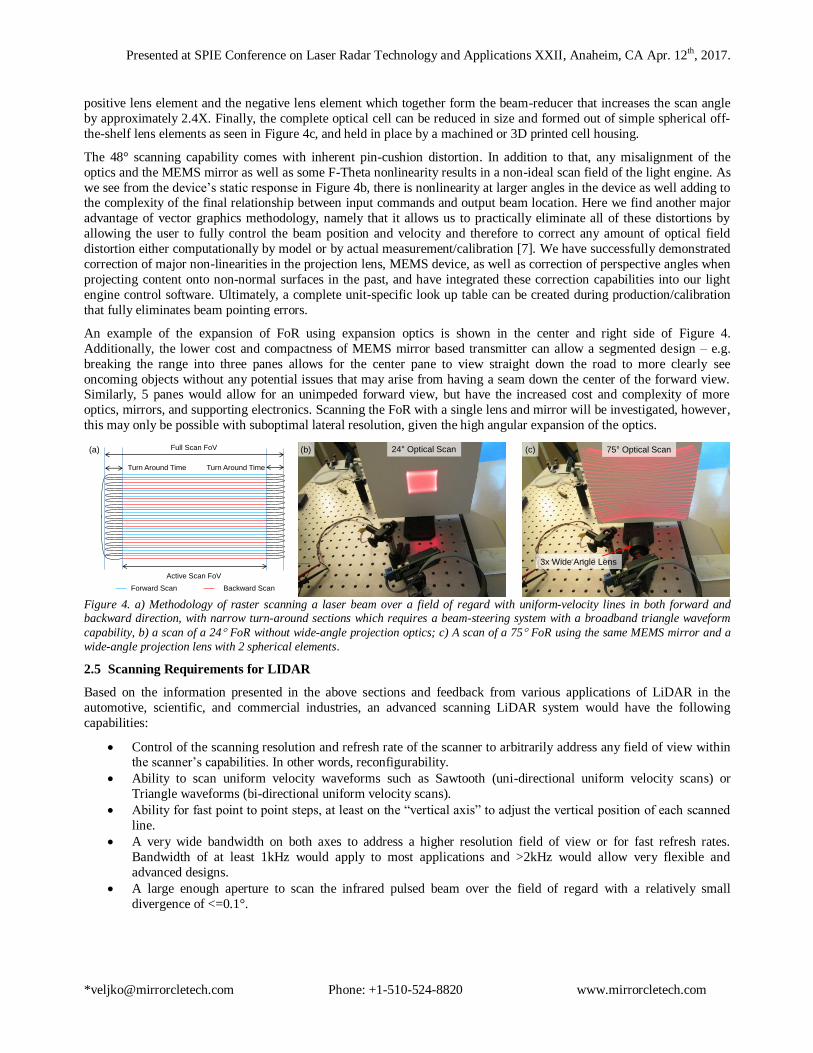
Figure 7. A frequency domain model representing the Inverse System Filter with 2 added poles in sequence with the integrated MEMS device as a 2nd order Linear Time Invariant system.
This can very effectively subdue the large responses near the resonant frequency and can also have extended bandwidth
in order to increase the module‟s overall bandwidth to resonance or well above the first resonance. The selection of the additional poles that make the inverse system filter realizable determines the ultimate final system bandwidth. Here it is
important to note the voltage/overdriving limitations of the MEMS mirror which would ultimately determine the
bandwidth for large (full-angle) movements. The filtering can be performed in software when the driving waveforms are
initially generated. Or it can be done in real time where it typically involves a processor or a micro-controller to digitally
filter the waveform content that is streamed to the MEMS driver before converting to analog voltages. In Mirrorcle
MEMS applications, the scanning waveform is pre-processed on a host computer before downloading to a micro-
controller or a DAQ card to drive the MEMS device. There have been a few applications where the filtering can also be
performed at the MEMS controller level, onboard the embedded micro-controller (MCU). Recently in 2016, we have
also implemented this 2nd order filter as an analog filter using op-amps and passive components.
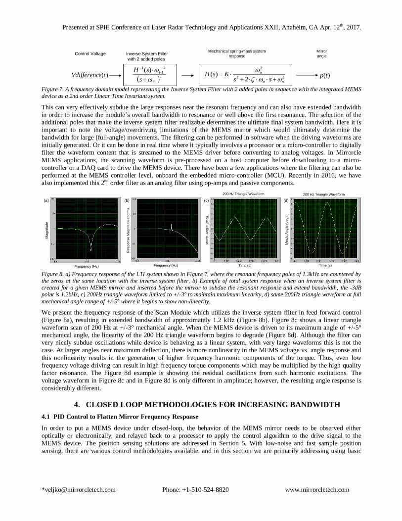
Figure 8. a) Frequency response of the LTI system shown in Figure 7, where the resonant frequency poles of 1.3kHz are countered by the zeros at the same location with the inverse system filter, b) Example of total system response when an inverse system filter is created for a given MEMS mirror and inserted before the mirror to subdue the resonant response and extend bandwidth, the -3dB point is 1.2kHz, c) 200Hz triangle waveform limited to +/-3° to maintain maximum linearity, d) same 200Hz triangle waveform at full
mechanical angle range of +/-5° where it begins to show non-linearity.
We present the frequency response of the Scan Module which utilizes the inverse system filter in feed-forward control
(Figure 8a), resulting in extended bandwidth of approximately 1.2 kHz (Figure 8b). Figure 8c shows a linear triangle
waveform scan of 200 Hz at +/-3° mechanical angle. When the MEMS device is driven to its maximum angle of +/-5° mechanical angle, the linearity of the 200 Hz triangle waveform begins to degrade (Figure 8d). Although the filter can
very nicely subdue oscillations while device is behaving as a linear system, with very large waveforms this is not the
case. At larger angles near maximum deflection, there is more nonlinearity in the MEMS voltage vs. angle response and
this nonlinearity results in the generation of higher frequency harmonic components of the torque. Thus, even low
frequency voltage driving can result in high frequency torque components which may be multiplied by the high quality
factor resonance. The Figure 8d example is showing the residual oscillations from such harmonic excitations. The
voltage waveform in Figure 8c and in Figure 8d is only different in amplitude; however, the resulting angle response is
considerably different.
4. CLOSED LOOP METHODOLOGIES FOR INCREASING BANDWIDTH
4.1 PID Control to Flatten Mirror Frequency Response
In order to put a MEMS device under closed-loop, the behavior of the MEMS mirror needs to be observed either
optically or electronically, and relayed back to a processor to apply the control algorithm to the drive signal to the
MEMS device. The position sensing solutions are addressed in Section 5. With low-noise and fast sample position
sensing, there are various control methodologies available, and in this section we are primarily addressing using basic
22
2
2)(
nn
n
ssKsH
)(teVdifferenc )(tp
Mechanical spring-mass system
response
Mirror
angleControl Voltage
21
2
1
1 )(
F
F
s
sH
Inverse System Filter
with 2 added poles
(a) (b) (c) (d)
Frequency (Hz)
Magnitude
Frequency (Hz)
Response M
agnitude (
norm
)
Time (s)
Mech. A
ngle
(deg)
Time (s)
Mech. A
ngle
(deg)
200 Hz Triangle Waveform200 Hz Triangle Waveform
Presented at SPIE Conference on Laser Radar Technology and Applications XXII, Anaheim, CA Apr. 12th, 2017.
*[email protected] Phone: +1-510-524-8820 www.mirrorcletech.com
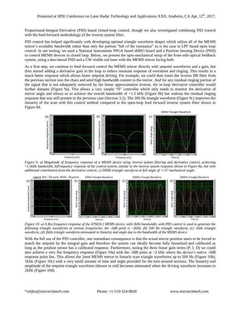
Proportional-Integral-Derivative (PID) based closed-loop control, though we also investigated combining PID control
with the feed-forward methodology of the inverse system filter.
PID control has helped significantly with developing optimal triangle waveform shapes which utilize all of the MEMS
mirror‟s available bandwidth rather than only the portion “left of the resonance” as is the case in LPF based open loop
control. In our testing, we used a National Instruments FPGA based sbRIO board and a Position Sensing Device (PSD)
to control MEMS devices in closed loop. Below, we present the opto-mechanical setup of the front-side optical feedback system, using a duo-lateral PSD and a CW visible red laser with the MEMS mirror facing both.
As a first step, we continue to feed-forward control the MEMS mirror directly with setpoint waveforms and a gain, but
then started adding a derivative gain in the loop to reduce resonant response of overshoot and ringing. This results in a
much better response which allows faster setpoint driving. For example, we could then insert the inverse IIR filter from
the previous section into the chain and send high bandwidth content to the mirror. And for any residual ringing portion of
the signal that is not adequately removed by the linear approximation inverse, the in-loop derivative controller would
further dampen (Figure 9a). This allows a very simple “D” controller which only needs to monitor the derivative of
mirror angle and allows us to achieve the overall bandwidth of ~1.5 kHz (Figure 9b) but without the residual ringing
response that was still present in the previous case (Section 3.2). The 200 Hz triangle waveform (Figure 9c) improves the
linearity of the scan with this control method compared to the open-loop feed forward inverse system filter shown in
Figure 8d.
Figure 9. a) Magnitude of frequency response of a MEMS device using inverse system filtering and derivative control, achieving ~1.5kHz bandwidth, b)Frequency response of the control system, similar to the inverse system response shown in Figure 8a, but with additional contribution from the derivative control, c) 200Hz triangle waveform at full angle of +/-5° mechanical angle.
Figure 10. a) A flat frequency response of the A7M20.1 MEMS device, with 2kHz bandwidth, with PID control is used to generate the following triangle waveforms at various frequencies, the -3dB point is ~2kHz, (b) 500 Hz triangle waveform, (c) 1kHz triangle waveform, (d) 2kHz triangle waveform attenuated in linearity and angle due to the bandwidth of the MEMS device.
With the full use of the PID controller, one immediate consequence is that the actual mirror position starts to be forced to
match the setpoint by the integral gain and therefore the system can ideally become fully linearized and calibrated as
long as the position sensor has a calibrated response. Furthermore, tuning the three linear gain terms (P, I, D) we could
also achieve a very flat frequency response (Figure 10a) with the -3dB point at ~2 kHz where the device‟s native -3dB
response point lies. This allows the 2mm MEMS mirror to linearly scan triangle waveforms up to 500 Hz (Figure 10b),
1kHz (Figure 10c) with a very small amount of time and angle provided for the turn-around sections. The linearity and
amplitude of the setpoint triangle waveform (shown in red) becomes attenuated when the driving waveform increases to
2kHz (Figure 10d).
(a) (b) (c)
Frequency (Hz)
Response M
agnitude (
norm
)
Frequency (Hz)
Response M
agnitude (
norm
)
Time (s)
Mech. A
ngle
(deg)
200Hz Triangle Waveform
(a) (b) (c) (d)
Frequency (Hz)
Response M
agnitude (
norm
)
Time (s)
Mech. A
ngle
(deg)
500Hz Triangle Waveform
Time (s)
Mech. A
ngle
(deg)
1000Hz Triangle Waveform 2000Hz Triangle Waveform
Time (s)
Mech. A
ngle
(deg)
Legend: Red – Set point, White - Response

Presented at SPIE Conference on Laser Radar Technology and Applications XXII, Anaheim, CA Apr. 12th, 2017.
*[email protected] Phone: +1-510-524-8820 www.mirrorcletech.com
4.2 PID Control to Flatten and Extend Mirror Frequency Response
Achieving the flat mirror frequency response was a first step with closed loop control. For the next step, the PID
controller needs the means to overdrive the device in voltage and in frequency to extend the device beyond its natural -
3dB point after its resonant frequency peak. This method uses higher frequencies above the device‟s resonance and
higher voltage than the device‟s natural operating range to extend the bandwidth. This is done by applying higher gains
on the PID controller to decrease step response time and ringing to achieve even faster setpoint response times.
We were able to demonstrate the A7M20.1 device to have a flat frequency response curve, with the -3dB point extended
to ~3.5kHz (Figure 11a). This allows the device to scan 2kHz triangle waves shown in Figure 11d with a larger portion
of the linearity and amplitude still present compared to the 2kHz triangle waveform shown in Figure 10d. This method
primarily works if the MEMS device is scanning a repetitive, pre-determined waveform such as a triangle waveform on
one axis, and a sawtooth on the other axis, addressing the field-of-view with bidirectional x-axis lines, and uni-
directional y-axis scan with a quick return at the end of the frame. Generating such a waveform with high bandwidth
under closed loop control can then be exported, and run from an open loop driver to achieve a similar MEMS mirror
response. This open loop driving using closed loop generated content has been demonstrated with various mirror sizes –
e.g. 5.0mm diameter mirror can perform 50Hz triangle waveforms at full mechanical angle of +/-4°.
Figure 11. a) A flat frequency response of the A7M20.1 MEMS device with 3.5kHz bandwidth, with PID control is used to generate the following triangle waveforms at various frequencies, b) 500 Hz triangle waveform, c) 1kHz triangle waveform, d) 2kHz triangle waveform attenuated in linearity and angle due to the bandwidth of the MEMS device.
With the over-driving methodology, the MEMS driver would require a larger bandwidth than the MEMS device for
overdriving in frequencies, and a larger voltage output range to overdrive in voltage. The BDQ PicoAmp MEMS driver
used in testing this application had a 25kHz high voltage amplifier bandwidth, with a voltage range of 0-160V. Since the
A7M20.1 requires the full 0V-160V voltage range to address it‟s full field-of-view of +/-10°, the optical angular range of
the device was reduced to +/-8°, and the leftover voltage was used for overdriving. We have demonstrated the compact
MEMS drivers to be able to drive from 0V to 200V, while consuming only 150mW. These larger voltage range drivers,
addressed as “BDQ PicoAmp-X200 Drivers” can be substituted into the control system in future applications requiring
the full +/-10° FoV.
5. BACKSIDE POSITION SENSING APPROACH
The gimbal-less MEMS mirror does not inherently include any position sensor to read out the mirror‟s angle on any axis,
or its piston position. An applied set of voltages of different terminals result in a mechanical position. To a large extent,
this position can be modeled and predicted from the device model. A simple linear model would be quite limited as
devices do exhibit significant nonlinearity when observed over all the possible driving and scanning conditions.
Especially for large angles of deflection a simple linear model is quite limited – as a result utilizing such a model to
invert the resonant behavior and extend bandwidth utilization has its limits for real products as shown earlier in Sec. 3.2. Therefore direct position sensing may be required to increase the performance and augment the model. Moreover,
position sensing is necessary for the safety feature of the LiDAR – to ensure that the laser beam is continuously moving
at or above some minimum scanning speed and therefore minimizing a chance of any person‟s eye exposure to the beam.
Since at least minimal position sensing is necessary for the safety feature and since an adequately closed loop controlled
mirror could more easily correct for all nonlinearities, resonance, and provide flat and wide bandwidth, we try to obtain
mirror position by different methodologies discussed in this section and also previously in [13].
(a) (b) (c) (d)
Frequency (Hz)
Re
sp
on
se
Ma
gn
itu
de
(n
orm
)
Time (s)
Me
ch
. A
ng
le (
de
g)
Time (s)
Me
ch
. A
ng
le (
de
g)
Time (s)
Mech. A
ngle
(deg)
500Hz Triangle Waveform 1000Hz Triangle Waveform 2000Hz Triangle WaveformLegend: Red – Set point, White - Response

Presented at SPIE Conference on Laser Radar Technology and Applications XXII, Anaheim, CA Apr. 12th, 2017.
*[email protected] Phone: +1-510-524-8820 www.mirrorcletech.com
Detecting the mirror position accurately is best done by optical means, by directly detecting the effect of the mirror‟s
tip/tilt on a laser beam. These involve using silicon detectors either on backside or front side of the mirror, illuminated by
a light source such as a laser, VCSEL or LED. For example, in one simple case a simple low-power CW laser beam is
used and deflected off the front-side of the MEMS mirror toward a position sensitive detector (PSD) place in proximity
of the mirror. This beam and the sensor are placed in front of the mirror for sensing purposes only and are not utilized as
part of the LiDAR application. It is clear that placement of such a sensor on the front side could easily result in difficulty for the optomechanical arrangement of the application laser and optics.
Another methodology we have explored in some detail is position detection from the MEMS mirror‟s backside. Backside
detection is achieved through an emitter/sensor assembly mounted under the mirror. The package of the MEMS has a
hole allowing an emitter to shine light on the back of the mirror. The reflected light is measured by the sensing pads. The
measured light is used to determine the position of the mirror thus allowing direct control of mirror position. The
mirror‟s backside can be clearly seen from the backside of the chip since the structure of the MEMS chip has a through-
wafer backside cavity to allow for full range of motion for the mirror.
5.1 PSD-based Position Detection Module (PDM)
The simplest form of detection of scan angle using a laser beam and a 2D PSD can also be arranged on the device‟s
backside and can have very good performance. Due to the need to have a laser source pointed at the mirror as well as a
PSD, both are arranged in a triangular arrangement to allow clear view of the beam, the mechanical structure can be
relatively bulky when compared to the MEMS mirror itself. The cost of the duo-lateral PSD can also be a concern in this method. We found this methodology to work great in cases of MEMS mirrors with very small angles (e.g. +/-1.25°)
because the PSD could be quite small and inexpensive (4mm x 4mm) and the triangle of the laser beam from its source
to the reflected beam off the backside of the mirror onto the PSD, could be set up with small angles of incidence. This
method has been demonstrated by the PDM shown in Figure 12b, where a VCSEL source and a 4mm x 4mm PSD are
used in the backside positioning optical-feedback system to control a 9.0mm mirror, capable of actuating +/-1.25° mech.
angle, with a bandwidth of ~200Hz. Demonstration videos of this MEMS Mirror Scanning System are available at [18].
Figure 12. Scan Module with PDM in a closed-loop control based MEMS Mirror Scanning System: a) A 9.0mm mirror MEMS mirror
with a backside-mounted PDM, b) Scan Module with PDM seen from the backside where the PSD, laser, and sense electronics are compactly mounted. c) An example of the position sensing waveform (white) and drive waveform (red) of the system captured by the FPGA Controller and displayed in LabView.
5.2 Quad Photodiode-based Backside Position Sensor (BaPS)
For cases where compactness and cost reduction are important requirements, we explored variations of backside optical
position sensing that are „flattened‟ related versions of the PDM assembly described above. In one option using beam
splitting optics, a highly compact PDM was demonstrated. Noise and cost was reduced by moving to a quad photodiode
sensor [13]. Toward an even more compact realization, we explored an architecture in which an emitter is placed atop the center of the quad photodetector with both “looking” up toward the MEMS mirror‟s backside which is only ~2-3mm
away (Figure 13a).
The purpose of the quad photodiode detection module is to actively determine the mirror tilt by measuring how light is
reflected from the backside of the mirror. Its main advantage is the form factor of the module (Figure 13c). The
photodiodes can be smaller than the MEMS die and mounted close to the backside of the MEMS package. The position
sensing works through a silicon quad photodiode which is split into four quadrants, where each quadrant is a single
separate photodiode. A light source illuminates the backside of the MEMS mirror and when the mirror tilts, the four
(a) (b) (c)

Presented at SPIE Conference on Laser Radar Technology and Applications XXII, Anaheim, CA Apr. 12th, 2017.
*[email protected] Phone: +1-510-524-8820 www.mirrorcletech.com
photodiodes will each measure different readings. The differences between photodiode pairs are approximately
proportional to the mirror tilt and therefore based on the readings of X and Y differences, the mirror position can be
determined.
Different configurations can be introduced to the module to improve the fidelity of the measurements increasing the
signal-to-noise ratio (SNR). SNR is increased by increasing the signal and/or decreasing the noise. Increasing the amount
of light reflected off the backside of the mirror by placing the light source closer to the mirror, the signal measured by the photodiodes increases. Optical filtering will help reduce the noise that may come from ambient light or from the front
side laser. Packaging can also be used to isolate the photodiodes and emitter. Our produced BaPS device involves two
stacks of PCB packages where the MEMS device is attach to a package with a hole directly behind the mirror to allow
underneath light to shine through from the position sensing module (Figure 13b). The module is enclosed inside an
additional housing to prevent ambient interference from affecting the readings.
Figure 13. Scan Module with BaPS for closed-loop control based MEMS Mirror Scanning Systems: a) BaPS circuit board showing the LCC20-mounted quad photodiode sensor, centrally-mounted emitter, and the first stage transimpedance amplifier. b) Scan Module MEMS mirror PCBA placed on top of the BaPS assembly, c) a custom prototype where compactness requirements were paramount – BaPS LCC package and MEMS LCC package are each assembled in a small and thin flex PCB and affixed together into a compact stack .
6. RESULTS
With the use of an optical feedback system and closed-loop control, we have demonstrated that the utilizable bandwidth
of the A7M20.1 integrated MEMS device with a 2.0mm mirror can be significantly increased from ~600Hz in low-pass
filtered open-loop driving. Since the natural -3dB response bandwidth of the MEMS mirror is wider by more than 3X
(~2kHz), we explored different ways to utilize all of that available bandwidth. In cases of period repetitive waveforms where appropriate effort can be put into input shaping of the waveforms, even in open-loop driving it is possible to
utilize all of the bandwidth, especially with the aid of the presented inverse system filter. However in cases where full
programmability and reconfigurability of the scan pattern is needed, we find that closed-loop control based on low-noise
optical position feedback is the only way to allow full utilization of the bandwidth. A flat response with a -3dB point
near or at the same point as the natural MEMS response becomes quite trivial with a relatively fast MCU or ideally an
FPGA. Finally, with higher gains and overdriving methodology, we demonstrated that we can push the bandwidth of the
2mm diameter A7M20.1 MEMS device beyond its -3dB point, up to 3.5kHz (Figure 11) and still achieve large-angle
waveforms for LiDAR applications. This increase in bandwidth enables this 2.0mm MEMS mirror to address all the
points mentioned in Section 2.5. The MEMS device‟s natural ability for quasi-static scanning allows for arbitrary control
of the scanning resolution and refresh rate of the scanner to address any field of view within the scanner‟s capabilities.
The increased bandwidth of the closed-loop controlled MEMS device allows the device to scan uniform velocity waveforms such as a Sawtooth (uni-directional uniform velocity scan) or a Triangle waveform (bi-directional uniform
velocity scan) at high resolution or fast refresh rates. Furthermore it allows very fast stepping for the 2nd (vertical) axis –
which is significant for line to line adjustment as well as for the minimization of end of frame re-trace time. The 2.0mm
mirror also provides an adequate aperture size for the pulsed laser to be scanned over a wide FoR with low divergence.
(a) (b) (c)
Presented at SPIE Conference on Laser Radar Technology and Applications XXII, Anaheim, CA Apr. 12th, 2017.
*[email protected] Phone: +1-510-524-8820 www.mirrorcletech.com
REFERENCES
[1] A. Kasturi, V. Milanović, B.H. Atwood, J. Yang, “UAV-Borne LiDAR with MEMS Mirror Based Scanning
Capability,” SPIE Defense and Commercial Sensing Conference 2016, Baltimore, MD, April 20th, 2016.
[2] R. Moss, P. Yuan, X. Bai, E. Quesada, R. Sudharsanan, B. L. Stann, J. F. Dammann, M. M. Giza and W. B. Lawler, "Low-cost compact MEMS scanning LADAR system for robotic applications," in Laser Radar Technology and
Applications XVII, Baltimore, MD, 2012.
[3] E. Ackerman, "Lidar that will make self-driving cars affordable [News]," in IEEE Spectrum, vol. 53, no. 10, pp. 14-
14, October 2016.
[4] B. L. Stann, J. F. Dammann and M. M. Giza, "Progress on MEMS-scanned ladar," in Laser Radar Technology and
Applications XXI, Baltimore, MD, 2016.
[5] Mirrorcle Technologies, Inc. Website, Support Page 2017, http://mirrorcletech.com/support.html, March, 2017.
[6] A. Miner, V. Milanović, “High Temperature Operation of Gimbal-less Two Axis Micromirrors,” 2007 IEEE/LEOS
Optical MEMS and Their Applications Conf., Hualien, Taiwan, Aug. 12, 2007.
[7] F. Kadribašić, “A MEMS Mirror Laser-Guidance System for CDMS Experiments”, Stanford Undergraduate
Research Journal. Jun. 2013.
[8] V. Milanović, “Linearized Gimbal-less Two-Axis MEMS Mirrors,” 2009 Optical Fiber Communication Conference
and Exposition (OFC‟09), San Diego, CA, Mar. 25, 2009
[9] V. Milanović, A. Kasturi, J. Yang, F. Hu, “A Fast Single-Pixel Laser Imager for VR/AR Headset Tracking,” SPIE
2017 OPTO Conference, San Francisco, CA, Feb. 2017.
[10] Spectrolab Website, SpectroScan 3D MEMS LIDAR System Model MLS 201 Datasheet, 2012,
http://www.spectrolab.com/sensors/pdfs/products/SPECTROSCAN3D_RevA%20071912.pdf, March 2016.
[11] V. Milanović, K. Castelino, "Sub-100 µs Settling Time and Low Voltage Operation for Gimbal-less Two-Axis
Scanners," IEEE/LEOS Optical MEMS 2004, Takamatsu, Japan, Aug. 2004.
[12] V. Milanović, A. Kasturi, J. Yang, Y.S. Su, F. Hu, "Novel Packaging Approaches for Increased Robustness and
Overall Performance of Gimbal-less MEMS Mirrors," SPIE 2017 OPTO Conference, San Francisco, CA, Feb. 2017
[13] S. Richter, M. Stutz, A. Gratzke, Y. Schleitzer, G. Krampert, F. Hoeller, U. Wolf, D. Doering, "Position sensing and
tracking with quasistatic MEMS mirrors," Proc. SPIE 8616, MOEMS and Miniaturized Systems XII, 86160D, March, 2013.
[14] V. Milanović, A. Kasturi, V. Hachtel, "High brightness MEMS mirror based head-up display (HUD) modules with
wireless data streaming capability ," SPIE 2015 OPTO Conference, San Francisco, CA, Feb. 2015
[15] L. Keesey, “NASA Team Advances Next-Generation 3D-Imaging Lidar,” NASA Website, Nov. 2014. Retrieved
March 2017 from https://www.nasa.gov/content/goddard/nasa-team-advances-next-generation-3d-imaging-lidar/
[16] Mirrorcle Technologies, Inc. Support Page, “Mirrorcle Technologies MEMS Mirrors – Technical Overview,”
http://mirrorcletech.com/pdf/Mirrorcle%20Technologies%20MEMS%20Mirrors%20-
%20Technical%20Overview.pdf, March 2017.
[17] A. Kasturi, V. Milanović, J. Yang, "MEMS Mirror Based Dynamic Solid State Lighting Module," Society for
Information Display 2016 International Symposium, San Francisco, CA, May 24th, 2016.
[18] Mirrorcle Technologies, Inc. Website, Media Gallery/Videos Page 2017, http://www.mirrorcletech.com/video.html, March, 2017.