materials f:ng inecering - digital library/67531/metadc283221/m2/1/high...lng proibl il) o t olso of...
TRANSCRIPT

. Itr i ion \ t te car "
. 'BR Fuei!- and .\Materials
F:ng inecering and V-l-'lupniwnt
t VC-7, a b)
ANL-77- A
ARGONNE NA TIONA. .ABV)RATORNY9.700 South Cass AvenaeArgonrae Iilino is tj0439
PPA(.'. I S FOR f SI I.G SMOOTH AND RI3BED TUBINGWITH PI' LSED EDDY CURRENTS
by
A. Sathtt
Materials Science Division
\lav 1978
rpfc.
" M r "".... - Vr~ - w sr
*e ~ .
- - -V __


)
IAI.E: O1 CONTENDS
Pad!
A BS 1 I:A C L . . . . . . . . . . . . . . . . . . . . . .
I INTID0I)T'C1 ION . . .
i1. 1i iF.ORY OF OPERA lON . . . . . . . . . . . . . . . . . . . . . . .
Ili. C lIRCU 1!1 Y EA I 'A ES . . . . . . . . . . . . . . . . . . . . 8
-\ A XF~P 01 SAM~p1.F. P01N
.\ t'S'. (I . I ANSI)tICE RS .. . . . . . . . .
\1. F P ER I.(G. ... ; ... . 1
'.-I I.R PRE AMPI.IFIEV . . . . . .It
.. Pt LS FORMING N-:E Wo( K FOR WA I..1- I IIICKNE:ss PROBE.: It
k A :..1:(A LIO. . . c
S'A',N iNG . . .. . .. . . . . . . . . . . . . 17
. ( i.t'S IO N .;. . . . . . . . . . . . . . . . . . . 17
A I ..\N I : (ircuit-boa-ird Elec trical Diagram s . . . . . . . . . . . . . . . 18
R E F.F EN C E ) . . . . . . . . . . . . . . . . . . . . . . . . . . . . . . . . . . . . .

4
LIST OF FIGURES
No. Title Page
I. Pulsed Eddy-current System in Its Simplest Form. . . . . . . . . . 8
. Voltage Developed across the Defect-transducer Pickup as a
Function of Time with Lift Off as a Parameter . . . . . . . . . . . . . 10
i. Voltage across the Defect-transducer Pickup as a Function of
Time for a Normal and an Inner- surface-defect Tube. . . . . . . . . 10
-1 Voltage across the Defect-transducer Pickup as a Function of
Time for a Normal and an Outer- surface-defect Tube . . . . . . . . . 0
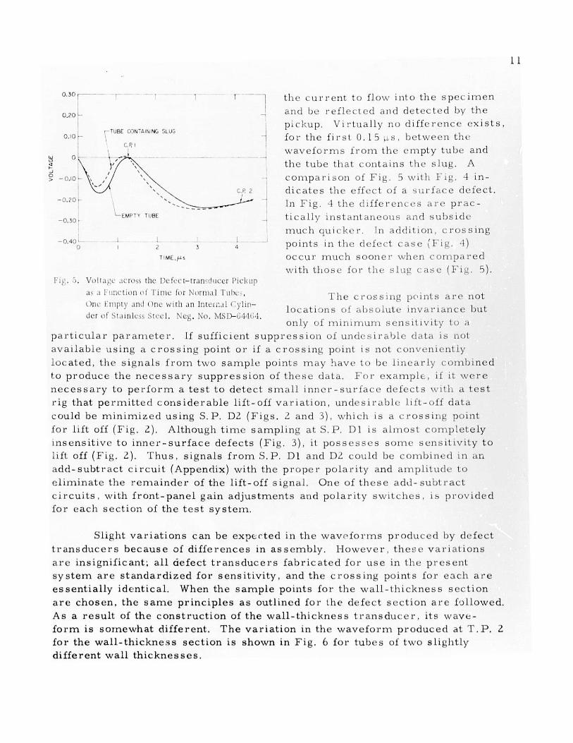
. Voltage acr oss the Defect-t ransducer Pickup as a Function ofTime for .N>rmal Tubes. One Empty and One with an Internal
C''linder of Stainless Steel. . . . . . . . . . . . . . . . . . . . . . . . I
t. Voltage ac ross the Wall-thickness Transducer Pickup as a
Function of Time for Tubes of 'I wo Wall Th-i cknesses. . . . . . . . . 1
7. View of the Specimen End of the Defect-detection T ransducer
fo r Sm ooth T ubing . . . . . . . . . . . . . . . . . . . . . . . . . . . . . . . 1
8. Vicv. of the Spec nien End of the Defect-detection T r-a nsduce r
fo r R ibbed l uh ing . . . . . . . . . . . . . . . . . . . . . . . . . . . . . . . . 139. View of the . pecimen End of the WCall-thickness Measurement
I ra n s d u c e r. . . . . . . . . . . . . . . . . . . . . . . . . . . . . . . . . . . . . 1
10. Defect Sensitivity iP;attern of Typic aA Pulsed Eddy-cu .rent
Iransducer Optimrnally Located with Respect to a 6.35-mm
Outside Dliaiueter Tube with a 0. 3i-nn Wall Thickness . . . . . . . 14
1 1. Filtered and Unfiltered Results from Pulsed Eddy-current
'est of Tubing with EDIM Inside Diameter Notches. . . . . . . . . . . 1
1. Fil'.ered and Unfiltered Pulsed Eddy-current 'Test Resultsfrom a Sample 1 ube with EDM Outside Diam,,eter Notches . . . . . . 15
A l. B lock D iag ram . . . . . . . . . . . . . . . . . . . . . . . . . . . . . . . . . 18
A Z. Sy stem C lock . . . . . . . . . . . . . . . . . . . . . . . . . . . . . . . . . . . 18
A 3. F ie ld -co il P u lse r. . . . . . . . . . . . . . . . . . . . . . . . . . . . . . . . . 19
A4. Pickup Preaniplifier for Defect Section . . . . . . . . . . . . . . . . . . 19
A i. Wall-thickness Section Pulse-forming Network . . . . . . . . . . . . . 19
At. Wall-thickness Section Sampling Gate . . . . . . . . . . . . . . . . 20
A7. Defect Section Sam pling Gate. . . . . . . . . . . . . . . . . . . . . . . . . 21
A8. Wall-thickness Section Broadband Filter with Add-Subtract
C ir c u it. . . . . . . . . . . . . . . . . . . . . . . . . . . . . . . . . . . . . . .. 2 2

5
LIST OF FIGURES
No. Title Page
A9. Wall-thickness Section Broadband Filter Inverter Buffers . . . . . "2
A10. Defect Section Broadband Filter with Add-Subtract Circuit . . . . 23
All. Defect Section broadband Filter . . . . . . . . . . . . . . . . . . . . . . 23
A12. Matched filter . . . . . . . . . . . . . . . . . . . . . . . . . . . . . . . . 2
A l 3. Pow er Supply. . . . . . . . . . . . . . . . . . . . . . . . . . . . . . . . . . . 24


7
APPARATUS YOR T TESTING SMUIO'II AN'u u IBBlD: 1 I'IING
W ITH PU LSED E' ;I IJiiRL EN i'S
A. .athe r
\BS1 R A(:T
The usO of outSide (ldiartIert rIbs 0( ilucloa r roactlAr
t ulbing pt'tsf t S Seve re P l u lb l1ls t n cOnld st 1L It iVI' t est iLg (,f
1I11S tulbnll;'. A ptlsc(1d oddly -(ir oIlt appilarattIs Ilr LLspHIt illg
1b0 inrtc r! . ty of sinooth1 (11dl r1bb))0d tbiiniig hias"* 1 bJL n (lc.OIp -d
at \ ArFl 01 LII' N at icnal I.a r at >ry . ' I s 1 Isult for tilLS tpl)>
'at <. cdL(1 aia y IVSLS ar1I(d ci l tl . 1I)oc h (Iitg rail , <t I' l)Fr S(t'lt t(d.
Il t dIcLt il>n, t ralls (IcL 'r it l l })rt- ct 11)h f i," r t' i ll 's S, st' i L i)L
ipr( ( cduircs. ;111( til O)r~y cot ,I)c 0 tItItLI It! (rl d c lssed. I I d-itt
tills d) Firar 1 . ha pr0vL(It- ( tiLt. )1St S > it L 1 1 I ( tI 1h IL bb dcl iLt>
Lng prOIbl IL) O t OLsO of its capabiIL Iy tI t II L -sa 1111ip - 11.LIa.
I. IN I l0I )I C'l ION
Severe prFOlcillS OCclir n1 Lide't u t LX"' t I-:s 1L. of 1110c leal" r(eaCtor
tul)i g w\itIh ou ts i (1o d I d It iritI > pFls - d <(ddy - FrLt' t tppIa rattis fo r in -
s pc! itlg tiht Lilt Lg r It y (>f S ti c>th .il l(! :i A ibed ,ubi I2 . > L [ e l d (e I-opori at
Arg1 LcnLI tL zional 1..ab)Oratory (A\ .) I Lhc spa( {L) bJtwt'L tli prul)b ain1d the
Sall11I)I htS a Iway s po'se~l t (ld p'lbl-Iic 1 \wi1le ddy 'I 1 t'llt S aFt ' 1s5(d 1l 00011-
<lt* t ruc ltv to stinig. Thi S liit-Off probItlel1. v it' L1 <tail( 1)c<>mi(le cLit t Severe
\'AlLol tt'st Ill.' )l)b 0(d tii iilg, caLl 1 be JllilllLL/.( iLSilig pilS (l d 0(d1y ( ur l' lits.
SIrlpiillg of 10 pulses at voltage \\eaVo lill1 crFsSil'. p (lnts I (l Vit!F uUS
pJ) r F IlLcWt(" 0 I t ablos the pl- es lt pilscd cddyCrr - it System to 1 11111it i/e the
lilt Ofi 0"1101, wlllici. tILel becOllIOs d1lly a IllliI rF Ilit Irt*.' r1 0 t. (C )lll)LLiillg this
adv-tmilg _ c tnd th: use ft' a dIfIIl f i t lal pit ) .p systiLL1 ('Ii.ibl) 's IllSptcct loll 1
t110 Wall litt'grity of a tubo Witll O I -li,'il Ligl r'ils .It 11<011 fldlainti iniIg highly
accurate' riichainical spaci'ig.
II. 'Il 11-:k Y CiO 01 ':P A l ION
'l'h -eS s1nt oil features of >p)It-at itl <>I the pls-< (' -IddyL-cur relit test
system are as folhkws
.. A pulse of ciirrent flows ini a fii(d coil, wli11h pr'(itdt cS all electro-illtignetic field in the space that surrounds the toil liht- ilntonslty oI thls
elect romagnetic field varies with t w.

8
b. A system of currents is induced in any conducting specimen
within the field of the coil. The currents diffuse into the specimen and can
be reflected by discontinuities such as geometrical boundaries, defects, and
layers of material with different electrical conductivities.
c. These reflected currents are detected as pulses of voltage at the
terminal of a pickup coil located near the specimen.
d. The voltage pulse is processed by various types of circuitry to
extract pertinent information about the test specimen and present it in a useful
form.
Two of the most important advantages of pulsed eddy-current testing
are:
a. The pulsed driving current produces an inherently wildeband signal.
In principle, this peri.iits extraction of more selective information than can be
dete ruined from the test specimen by an eddy-current method.
b. The low duty cycle of the pulse permits generation of relatively
high peak electromagnetic fields around the specimen. Because of the high
fields. transducers can be designed with ruggedness and resolution that can-
not be attained in transducers used with conventional sinusoidcal eddy-current
equipment.
Ill. CIRCUIT FEATURES
A pulsed eddy-current test system in its simplest form is shown in
Fig. 1. A pulse generator produces a train of current pulses that flow into
the field coil and induce currents inVOLTAGE PULSES E ULATOR METER the s specimen. [he total Iulsed field,which is the sum of all currents flowing
in the coil and spec imen, produces a
train of voltage pulses at the terminalPULSE
PICKUP COIL GENERATOR of a pie kup coil . Thi s t rain of pulsesmust be smnoothed and filtered by the
CONDUCTING SPECIMEN (lemodulator before it can be displayed
on a metei.
Fig. 1. PuILd Idd\-IurrLiin S\ item i , !L sun-pl"s Form. Ng. \o. MSP- . Se rvice pulsed eddy - cur rent
instruments contain considerably more
function modules than the system in Fig. 1. The pickup voltage pulse mustusually be amplified before it is subjected 'u other signal processing. As thetest probe is brought close to a metallic specimen, thic voltage pulse, which isobserved on an oscilloscope, changes in a complicated manner. The extractionof all information from the pickup pulse requires that it be subjected to more

9
processing than simple demodulation. In the present system, this extraction
is performed by time sampling.' A pickup voltage pulse can be sampled at
various discrete time intervals (sample points), amplified, and smoothed, thus
providing separate instrument outputs.
The test system consists of two nearly independent sections, each of
which has four outputs, labeled WTI through W '11 and 1)1 through DI, respec-
tively (see circuit diagrams in the Appendix). Iii tu be toy:t ing, it is intended that
the section with outputs WTI through WT-1 be u.ed for wall -tlhickness measure-
ments and the section with outputs D1 through 1)1 for the (Vtoction of defeats,although the system is versatile and capable of many t heri a1p" .plicat.ions. Each
output of the two sections is associated with a part isu lir san iplh point of the
pickup voltage pulse. Each section has one trans diic e ;h 1r! 11 tr-I nsdIIu e rfield coil is supplied current pulses by a separate pulst r . 'I be p1iIsers are
fired alternately by master-clock circuitry (labeled system clock in the
Appendix), and the repetition rate of the pulses sent through eacl fiehl coil can
be adjusted up to 2 k1-Iz. A separate synchronizing p K-c is supplied by each
pulser, which facilitates oscilloscope ope rations. 'T in . plig is a con -
plished in the circuit , labeled sampling gates (Appendi:x). F'rI- t.It II sample
point, an external. c .,.nection, test point 2 (T. 1'. ), is providt.d thit can be used
for proper time adjustment and oscilloscope viewing of the picIp volt age pulse.
The signal outputs of sampling gates WT1, WT2, D)1, and D" a r: fc.d to add-
subtract circuits that can be used for reduction of lift-off si gnlIs. * In addition,the outputs of the defect-detection section (Dl through )"1) pvass through filter
circuits that enhance the sensitivity of the system to sm nail deft' s. The op-eration of these filters is discussed in Sec. \'I. lwC h sampling gtte is providedwith a front-panel zeroing control that reduces the his \'oltage ()f the particularoutput to zero. The bias voltage at any output can be monit ored by a front-
panel meter. The operation of the systern is not affected lby m11oderat(' (+10 V)c. ffsets. If the test system is connected to an analog-to-digital <onverter for
computer processing of the output signals, the zeroing controls are useful formaintaining the variation around a zero average vahle.
IV. ADJUSTMENT OF SAMI-11E POINTS
As mentioned above, information from the vul age pulse developedacross the pickup coil is extracted by sampling the wavcefurn at varioustimes. However, it is advantageous to carefully choose the tiiting of thesample points. Figure L is a reproduction of oscilloscope waveforms ob-tained at T.P. 2 from one of the sample-gate circuits of the defect section.The three curves correspond to three values of lift-off distance. Two times(not including the origin) exist at which the same signal is produced for all
ift-off sign'tis cause variations in tile system output and result tromt Cbl.ungk'l III IIIC -p.t 1IiL" hviwccn tite spacingbetween til test specimen and transducer. Inlcss tlhes signal, dtrC supprescd., Illy tuiy inttcrt'rc with theproper interpretation of the test result;.

0.30
0.20
0.10
-T
SR DI S.P D20 + -
-0.20
C--,
-0.30
-0.40
0.25 mm LIFT OFF
0.12 mm LIFT OFF0 LIFT OFF
2 3 4
TIMEf 5
F1g 2 Voltaic IDevceope acre., fihe 1)cfc ~ ttra nsdiuc cr Pickup a, I FuuICen oTI'Imc with Lift Wf l' a ,IIaralmeter.
as can be determined by a comparison
time sampling at C.P. 1 is insensitive
but is quite sensitive to outer-surface
point phenomenon is a basic feature of
test parameters, a crossing point will
1
two waveforms in Fig. 5 were obtained from a tube with and without a stainless
steel slug, which was slipped into the tube with only a few hundredths of a
millimeter of clearance. This slug simulates, for example', a restrainer in-
side a fuel element. The crossing point, that is, the point of minimum
sensitivity to internal conductors of this type, is obvious. l'igure 5 also
shows another significant feature of the voltage-pulse waveforms (level-
oped across the pickup coils: a finite time is required for the bulk of
0.30 '
0.20'
0.10 "
S PR DI . U2
-0.20
NORMAL T , jE --0.30 - TUBE CONTAINING LONGITUDINAL
1.5m LOG a /0 DEEP-0.40 -----
0 I 2 3
T ME.ps
Uu'. 3. Volta ,v at re~ thL' Ih tcI-trar1,dl( cI
Pickup a, a Functimi of FliunC for aNorillal I arid an lrulr- urtacc-dlef-ct
ITIu . NiL'. N . Ms i 4; :.
O,30 ----
0.20
0.10
- ---- --
S.P DI , ' S.P D2
- 0.10
NOMAL TUBE
-0.30 TUBE (UNTAINING OUTER SURFACE LONGITUDINALNOTCH 15 mm LONG . IU% DFFP
-- 0.40- i -j0 12 3 4
TIME . I%
Fi . l. \lllec ae o thll I)c'b-elt-trad u~hic'r1It'IC( p ,, .1 1 mit wrt ei I Itri for i
Nriulil arid .1n OIlt'1- tIac-d fc(.t
TIubhL. Nc '. 1 ,. -M 1 -1 7.
10
-J0
r
---~
three lift-off values. These points,
known as crossing points, are marked
C.P. 1 and C.P. 2. Crossing points
also exist for other test parameters.
One technique for choosing the sample
point is to time sample at a crossing
point, for a particular parameter, at
which satisfactory sensitivity to a
second parameter exists. The signal
at this sample point will then be a
function of the second variable but
not of the first. F r example, if lift
off is a problem and one wirhes to
detect inner-surface notches , choosing
sample point 2 of the defect section
(S. P. 1)2) to be at C. P. 2 will result
in low sensitivity to lift off but good
sensitivity to inner-surface defects,
of Figs. 2 and i. For this exampl(.to both lift-off and inne r -surface defects
faults. as shown in Fig. .. The crossing-pulsed eddy-current testing. With twoalways exist. In another instance, the
TUBE CONT4 CNG SLUG
-0.20
-0.30.
-0.400
EMPTY TUBE
.l
.T MI -
*i' I. \u ,r Icro 11 iC Ilcl fc -1-rIrm I'I- 1icli
0.30
0.20
0.10
,1) .1 1 't [l h l i 111111_' I J? , rllli I ' X [ I* OF, i pI ints are notl)h I li~iil\' ,lTJ 1 1[1 allocations (>! aL sI lute inva riance bulttlcr ., Ilnll ::I . 1. . ' t. ttil?-e; .}-r
Oily c"f ininin 1uni s ens itiiv itV t e I
particular paralmieter. If sufficient suppression of uneiesiral h- data is not
available using a crossing point or if a crossing point is not conveniently
jOcated, the signals fr om n two sample points ma navye to be l.inearly comii bined
to produce the necessary suppression of these data. I'o r examlplc. , if it. were
necessary to perform a test to detect s mall inner-suIrface defects \w111l a test
rig that permitted considerable lift-off variation, undesira blb lit-off data
could be minimized using S. P. D' (Figs. " and i), which is a crossing point
for lift off (Fig. L). Although time sampling at S. P. Dl is almost completely
insensitive to inner-surface defects (Fig. 3), it poss(5ses some sensitivity to
iift off (Fig. Z). Thus, signals from S.P. Dl aiid D2 could be comnbiled in atnadd-subtract circuit (Appendix) with the pr(ope r polarity and amnplitude to
eliminate the remainder of the lift-off signal. One of these add-subt ract
circuits, with front-panel gain adjustments and polarity switclhes . is provided
for each section of the test system.
Slight variations can be expected in the wavofo ins produced by defect
transducers because of differences in assembly. [however, there variations
are insignificant; all defect transducers fabricated for use in the present
system are standardized for sensitivity, and the crossing points for each are
essentially identical. When the sample points for the wall-thickness section
are chosen, the same principles as outlined for the defect section are followed.
As a result of the construction of the wall-thickness transducer. its wave-
form is somewhat different. The variation in the waveform produced at T.P. Zfor the wall-thickness section is shown in Fig. 6 for tubes of two slightly
different wall thicknesses.
the en r rent 1(o flow into the spec imien
and be reflect (d and detected by the
p ckup. virtually y no difference exists,for the first 0.15 . , bet\veen the
wavefornms i-oifr the em pty tube and
the tube that contains the slug. A
conparFi onl of Fig. 5 wit I'i g. 4 in-
dicates the effect of a surface defect.
In Fig. 1 the dlffe rences are prac-
ticall instant ali usell ann subside
m uch eIuI ke i. !In a(it Ion, c 1r( ig
points in tlie defect case J I1. 1)oCCur Iuch11 soone r when cor wIi red
with those for the slug case (Fig. 5).
w
11
1
I

12
0.30 -
0.2C-
0.I0, m, p Nn;
I rI
O i. H mm
- 0.40
V. DESCRIPT ION AND VSE 01 i' ANSI[ '0RS
1 he test system has t pes ty of tr;ansduccrs. one or dcIcc t lete ti
and the other for wall-thickness measurement. Each t ransdcL I'r ha- Uant
field coil. The wall-thickness transducer has one pie i1u1 coil tnd the tl c t -
detection t ransduce r has two, which act as a diffe reIIt i pi c kup oil. I he
defect transducer is designed for hiuh resolution. wh. h results in a Nort
point-defect respons4.3 A copper mask is used to pr 'duce a pulsed mna n ti
field with a sharp g'adiernt. which is lesi :. <v detect ion ,) -mall ('e-ec.ts.
This transducer is specifically designed t( ( detect tubi ngc delects th tt a re
predominantly longitudinal (i.e. those with the major dinens ion paratllei to nth
tube longitudinal .xis). smu al; ransverse defects also , an k deter ted wi ti.
this probe. Large transverse defects (I defects that cove more than I,of the circumference of the tube) a-,- detected with reducei sens it ivay wt vv hen
compared with the same Oc.fect oriented in the longitudinal ciireetii . I he
proper orientation of a smooth tube or fuel el Iemnw t un(e:r t}ht (1i fc. t : a U& e r
is shown in Fig. 7. This is best determined by obsetrvmi io an Os c iuos Ce Ujt.
When the transducer is placed such that it c erte r axis is c oa xiA a I it. thetube radius and "otaed, the aimplitude of the os i ilosc ope t r0. e ct n . For
the inspection of ribbed tubes, the proper tr,' sducer orientation .s sho-n inFig. 8. The ribs of the tube must be i: ralKI to the center lirne -)f the two
pickup coils such that no difference in balanc u of the coils is n Itc(d. T1hi
orientation angle . of course. will be equal to the angle of the rib. .Aiignmenl
must be performed carefully to ensure a di fe rental action from the pickupcoils when a rib approaches. Ii the transducer is prope; Iv aligned . the ribs
produce a small background signal, which c n he compensated by signall
processing. Proper alignment results in a minimum peak-to--peak voltageon the oscilloscope face for an unflawed spec il ieh II'he iocatlun (A the wval!-
thickness transducer is not as critical, it is placed in the position sho.fn .i
Fig. 9, which can be accomplished by visual aLignment

-J
O N
* xO <
0 <
o *
o V~
PIKP OL
. \ .. Spi! . i nc ut the Dtfect-
t - r SnmUkth Tubine.
Na . .. - -
M
*o 2
O Z
0-
0 20
PICKUPa+
rIELFCOILJ
1
COPPERMASK
I
4 "j
Vwr
;~p AN F
wF R
(i
*7
'iCK ~---. FIE[ 0 /PENT 1I,
fig. 8. \iew% ! tia spct inkrn Lnd ui the ik ele. r-
.Jut. t ion I rarnsdur ef or Ribhid 1 uban.'.Neg. No. MSI-47'.
Fog. id
Vic .i lkM. Specimen End of ti Wjh:-thi knc, M a i.wr moent I ratn'dm ar.
Neg. No. !b NW
7
r

1-;
Fhe r l 1troma~tgnet I fi-ei:s ;)rd(}':, c b)v the ileir: t :is l ) utli trtns-
d(.. er - weaken rapirly as th.- probe -to-spet imnen distan( e Int rease-. T his11!t tof , an .fft"t sy Al St Lnsitivity. C )'1'vS( I trLyv. 11th -p't .mA.enl tLt t mu 1 Slt
be % ithit' U 1 1111 of tie trot+-.ldule: (pref Aby ioser) l<T< !.< st sensitivity
.tV irge Spa( In l lf it oilf h ' ; mmui is a rccolmliende( value for most
:t' . t . tube- with rib U l , 11mm in n-iLht ( an he inhpei ted : ithi 'a the
p 'dut.S for -ett:Le the tume-samnpilng ui1ses larg ejirninate the lift- oI
siLnalS at the output ul th( test s'ystemn. they do not t imn)-1tt fr fo llr
th~i cnt'ss ( alibration nor de rudsus 1I dtct sensitvitv 1he am (unt I:lift -uofl \ :'iatlI n allow.abilu dlpunds '1pon thu a(c rac y requi red by t K tts'
lube wobbie (i.e . wandeTrint of the tiijtb loneitudinai axis on either Wide ~! t:(
transduk er ' enter axis I an also bt> a prublemI. expus iall\ with the de'I. t: ansdui. e. an( should be moimntm ned wi thin U .1 n(i, 'Xbble is Inore Ikelv
to produ C a 110is signal at the systetmi ()litput than to AiW t calibration
apprec iably
I'rift prb"61cns liay be cnt. tuuitered I \w.ll-thi' rless i11('t-n1:remtn.'nts
estpe ti ally \%when obtained on tucl e em.ents su1liciently a( til'e to p:ru' c t ie -
nilic ant heatin 'r itt orig!intates I ruim t'. U suurt1T es I il neutup t. samlpiine
circuits and .11mpliIer. 11(1 (1) temopeIrature-Indut ed th ines .n the t ransdu . er
\\iit I involve re ist I,ty o0 tile w.i re pe ei)hl1 , lit Oif the Ie: rit t .:'t .'I nd
expansion of the mui.ttrials. I hie fIrst !ouirce n1:ially ..t- u lme 1 ne1LmheUe at e--
Al nun of %wa rmn-up. 1niess severe hlle volta e Ihandt"e- are en.. 1Unt( . :ed. in
this case. use of a ine-voltaite regular is advisable
Be caus. the diect - ri..'t et ion t ransdc 4, n (it lt(1 o hav mu h
hiher result 1 n than the v. al - thickness t ransdn er ( coe'.' rs a '-.mall..r
an..l: of o1 the ::1me ren e tA) the tube A typo. al selsitivAtV- response '. .t
if) a (I':et -deteCt IOnt t ranisd'C. r is shown in - 1e 1 U l he ret pon -e -t trIn1
d(etenIdt lit q:.) . . ri: t at i( ( )I the t ti U-do t , ente t' i At 9e <I i
dt -t.( t
t TRANSDUCER RESPOhNSE
. .. t. J.:'-" " .:m~n i I .ain'dtlu c A.At
.1. ' .t " iI tA! M ltt f'. A l'f it TA'soocr rsos
-40 - -20 - Ln auu . 3
. I I I- -s -20 -00 0 sO 20 so 40

ult t vc c arrrn I iuld sie st .t td fur u.S in pu)l-u C(d(d\ - . renit
tt stS (. 2 ' pendc:i 11pon the l)1 t1 the de1 t ts to be dttet ted. I u fat iIlitat t
this silcI to il. 1ilt u rs have betn ist'S L:wed ft, the (eftt I -dlets l tion Sutot l o (i
th test S\ tltim I h fiItur -dus in philosophy Iha, beun (it St ribed( t'I- where.3-~
wo tt pt.- of Ii te r, atire isur( Ill th present test system br(>adhand n:d
matched I he ro idband filter is destned to provide mn.ixrimumin enhat tinwnt
i the s Lfnals from small dutuft \it ihout unat'ptal)lt (ist t ion and :e(dti thion
Wf th SiIinals from diufects that have aIppretIdibe length along the iu ll- elemnuntt iaddm :Lhe matc-h 1d fiI t' u d sigcn ed tu provide thu m1axImuni na] - to -
Oul-t" "atio fruim small (etft ts A itiobut r(I r.td to d- ' rt n T1-1 J A t tI ln of tile
w-. :..ttr , is shown in FI iv 1 1 h Ih dangtrs inhe :,:t it. th use u: only the
m1itt. hled f Iter are iliust !a -i.d in lig 1.. which shows tflu test-SyStriml OP111)11t
that result S f ruom 1- t i I1,"t tubt with sev erail outtr - 1. ":a . . longitudina 1.elvt. rc - (i-Ii hatr'h - m1a1. lit f D.It not(t hus Ti he .]hapt t1 these notcht's is
shown in a . ross-sE tal V iew of tihe tubc aI1 at the bottomi of Fi', 12 OfparticuIlar inters' t is thu response of th math led filter to the tin rd Int, L. frunthe Ktft I his long dtp defect wih( h .app'oxiI.itI tilt' duth versus lunIth
pr it d: many raCr.s . is almost comiplttelv attIuate(i Un thu other hand,
th t p.tbiity ol thit- matched filter to tiiprovu thu ig:nal-to-nulse ratio forsmlal (ieteftS is obvious
MAT Ni;t R
uif 'it TRE
E Iltt~cd an. .. ~ t ! !t ,u
frinmi Pil,'iu I uirrtmut I e,t
) Ti u:n with I I1.t inIdt
Ih:. n1< tt" '. t be . ,. tnlpit I"
.t -111111-d la I Vpk ' f t a nleettetl t~ta t i ".t a .. :!I tt1 tkn "
, i -',' t!1Ir. llntr-. rtat tet i I a. ' tI
. -t' m I.' i i It li '. 1L' .
MI)I- *:.
FilteredO anid tt I lttert" PEl,ted I .dy-t :art'tt I ettResult f I ., a II11)1c ' -l a b< w th I It , tl.t,ltl
lIharntt t :,it bes". NCO. !.. hM s -" .t

V I. 1'RANSDIV ER P1I'..:i. LIlIE'R
lile dt~e i t -d(t tt Iiml t ranlsdu(it 1 r riqul i s a prea illiphl it r I:\pp('nx i:
tlidt is IoC itt(i no( 1iit)rt than .Ill aiway. 'p of o I -) 11 U: iXi t l 0 al)li cal )t
US('d bettwleci thlt preallnpllfit'r .tnd( the 1trlmlindI"r of thet tt'tt sy ternl. 1l Ic
preaniplfier is Ilttn(Itd for opt :;itll \'ithil a tot cell. Actal.ily. the prt-
am1plifi circuIt con tists ()f thrit pr'talplllilitrs. alt1hough1 tlit (It fct-d ( 'l tlti'n
)In reqiii trs (mly W:.t It Oth r two at( prOV i(ile as hpart s aind 1OrVfl s n I l in :.( (vent 1: ,t idditiunal t ransdie t"ra .t!rt ust'd1 I hus. ;uftit i ti
traiisduct: prta:iplitrs 1(Ind sampling (i rt -iS a' aVaila-)t S1( , that tht
systteml can t'asin, I( b ( i o verit'( to) a 111r('(-lt ranl duc 'r' defeet t-d("t(.t tIOn s\ t t Ill
With t\wo salplit' T)Ollt S p'r i rainsdC'tr nditnI . t ii -t hilt AnIH- sy+'ttiH with oit
trIiinsduc r ar. ' Salliplt poillits. Nutt that lit prtamiiplfitrS haVi a ' witch
It r mnilput p) i .
1i1 1.Si:- FOlRMIN( ;L i W\k1K 1(1 W.\!.i.- 1I h( .N: vS IT'OIui
! hi, "im all 1)<,x 11h.1 (O o ttills tiI(- puIllst lurrung nt't\\<>rk" 1: Im itttd vwar
thlt wali -th1ti ltne !- pr,)"w I'\ppcindix .1 1; i1 n gtht 111 l abl h. bt .ted be"l ('I -
tvtcll this box t aid tlt main Chassis. 'I li ;0-. ti'rlliiiatlon ritSistt)r I- I: tilt
iitill l'lilisss
Il C. 1.1ik': 1 TI)N
\'arIous depthll. of }.I l'\r lt ~ n .-. . e m D . il Ilsr ion (,f thlt
detfect-detct Ion ,'ectio \\' ith1 a 1 ranl." hiver'1 lilt OHi (I 1 . 1!111, Ht - tc'' ,y tt'tn
t'aslly dtlt etr t!- both Innur- and sttlc.--Surfa- 't lonultudinlal nmt( bies tha.t it e
(Id pth1 (01 10,- o1 the wall thut knt:-s and (i lnti ht1l of 1. ' o HIu .>t 1tnsitivit\ I" il-
Vrtdst'tI with sniiller \'1hit s ( it lilt t(It . \ . -1n1 tra111 rl'\t notli r9V(( i'tt
a ' ,.1l \\ ith all illplitu tt .ippi ) - Xiliattly t\\ , ti-thl rds t hait f<>r t1ll. , Hilt. itt- i . h
lot dt t-i IuOn it ulldInal Iv. Short r itill' t S o it i t" 1) )ihIll( c c! si' t IL illv the~c
Siilet siLgliti aS it1 i'tintic l noi t ii lOt , i ttl -'.2 itd(IllitI\ I lit' stn.sit Ivit\ Vt'-
(i ired i,r thie (lttV t timll of snialli oti .' nut l)t' Mci t S .t r\ In ht -( 'll
work. pa rticularly on hip1'n-11 bur Iup fuIt'' itlIcfltS. \ V'tyV cv O1 pru)bl ris that
dt) not tt 1 11 I I lit\ I iiblIl iL: be i it. (,tIItt ' d In ja t'i t s ii) tit - Ii I I t hIt'll t s
( altl)r1 ttion of tiht' sv sIt"ill oIl a SIll It' i.! :1 t'(i n( t(1 t :ut \'a i I \'.1Liii i iny
d{tt'11s txIst SIn i,!trnl'usiv illtt ly in t' ,i I d :t nh, - V educe r In tills t atS a
i.111 I( (1 It Ili t' ouit put s .i :i i u usuallv resill,. \. hi% hi c.t:, ad to O\' V'I't 1 intl ion
Of tihl !ina iIIlil n <d t! t 1 dcplii.
\\ ll- 1h1 k k ec Ss - ,t:,(Iit i( 1r !'( l:( t ( nv r t l y 1r 1par ({ b)\ Ch nt 1 i
(c hi ii pl t l(' r ini it \ v V.tIri u s tlt h lit t* S I'oill lt i n ittn r rIat. i. a sIort tt -
1l(i <>! tu b1)lne \'. 11h the' ,.1111 Iz e (' . .(I t 1)11 1p1 X11 X , fit t1:1,1nd tO I)<- rIlll'tsllred.
\t'Vt :'ti Ilj( !' I l l S tt i t ilis (1 (til It'r ilit \\.tiI It 1lnt's '.S t itn I)' .tsistl' ullicd
Ill ill .1 r ra\ to a t 1 i . I 'tt itln .'.I tidlit!'(1 li >\\ t t'V!. t is t\ po' (,1 t illdti rd . \w i It h
hats a r l aitivly'' +I11(,(th inlile l l tl tl (' 1 n ,t t'p\ -t t'(1 >( l.it IlItati - r' " t I )b t'1) 1rt'(lit I ti \ll itt ' lt I tIlnili g [12 ill t I , tV V ad itt'd '.uit i t It'! il)lit It \\.tiI till till g iiI
tlt' foli,' t'li 1tit f1Mas ii'tH 1)t'+ itldt'(I ,\ I . t[rV t 'ss t aIi.t i Vt'.ttc's .il I r i g itr

17
cladding linn I Su rIac or m Iletallic fission products lavt ic t c In Jl ittc d wit illn
the fi("ld tat the pr ;,bt. the pitlscd (Iddy -(1urr(nt C(Iulppm tl can Only be rclII(d
lluo to indli t t" hilt cxISt c e ' ntId IM. atImn Ot .11 ;iblO rm111111ty W or (). n tl tht"
dt've lop llnt o staInda rds and in'tlh m s >f it t"it 1 U)-r ct ,t to1 ( >f p ilsod ed - ir rent
tests oi I r rbdIat cd fu 'l t'ltim t'nt s has Onlly rt iitly l n'icti dl at AN a di 1d illt I'
IocatioIns
N. SC\NNIN(
Ilie 1p resent pulsed eddy - current syst'Ilm has lbt Ln d-s i'ii-d f(r I ' t stS
in which the futel cLt'it'nt Is longlitu(iIally Scilin'd and(l t' ir1tIilfLt'U'I't IAll\' in1-
d( xt(d until thc entire surface ' 0o t110 tUbt h'lis I)'t'I1 iispeL'te(. Tliii5 t 1p- of
Scainlillig usually prL)duc S the bef t signiI -t(,-:1imse rat I> at t >' it pit >t t leItIfect sectionl. Sl-)w spiraling 01 the fuel cL' nlt Ii t rtIlative 1(1t ilL t rIls I t 'r
i't I it pitch of h() 111m11. 1pr)duce ess ent Ially tlL ' a.mi'.' result as I I1,-it u1Id Ha I
tit .nnin 1114 Scanlning wVitl a bung-pitch sr1)1UIt has been suito'st'ully udt 11VA'( test.
at least parti t ally. fuel cIcII I t s and caI)suL' with h I t' s p'l' I1 \i I ir S stib
attach (l. Rapid spi I lmg w4 ith1 a smalliI pitchI. \\l11ch is n1te c s isry fo - It rastoifIL'
tube tt'st Iig.I is llot rLecoilifli'nlded. 11e filters us.'d i lith (t It s t Im have)een designed for a scanning velcity of 12 i n1111 jor ti' t rI !S (luc r1i r!L' t IvLto the tube surface. Use at any L>tht'r speed results ii h1l2 r.I(at ion oh iilt tI
p1t'Uforiliance. Ilt oIlighi var'lations of 1 ' hiavt lilt Lt'1 t ' ('t. U' ( tirU t', t lI
wia tI I hicknes" imnasu 'irteit section, wh1lic'h has no illter , t n lb e used ,t
any PrUacti al scann Ing 1 speed.
Many it.thnds of scanning are available that t'nsurt L ovt'rage th,eitiUe fuel- ('lenient surface by the ltfect-detection t irnsdu( t U. Oi1 e th1e(on(lit ions of the test (such as the r; .eui red sensit ivity and the it' chainc.II
scanning and positioning ar rangem'tents) have t'ibenI deternln .d. the ll'tub
imldexing: inc remeL'nts can be selected by refe r' ring to Fig. 1 (.
XI. CONCLUSIONS
Iuls di eddy-current testing with time saiplimg is a viablt' nithtlod fur
the inspection of smooth and ribbed tubing. The capability of tih ' method to
test integri Ity as well as Incasurie \wall thickness with great A(, iUra y. v'r-
coining lift-off interferiece, makes It one of the most valued nondet rutt ivetesting tools for tubing available at the present time.
The separation of defcct data obtained from the ine I and outer tube
surfaces and measurement oI wall .hI(ckness at any point along the tube, coupledwith the speed and accuracy of an electronic test, provide all the Inform'ation
required for a good nondestructive evaluation.
Pulsed eddy-current equipment is not difficult to operate and willsurely aid in solving many other nondestructive testing problems.

18
A I'1) EN 1I X
Circuit -botrd Electrical Diagrams
CIrc IIt dia graIms for 11 pulstd eddy-current test systern are presentedin Figs. Al-Al i.
. 1,IA*)II
" -- 4
( A
NH 11T"
A
.. .. r{,rIK
'A . -
veal, M I- )
V f S
'A.
f P I AL
w' 2
"
AT 3
"
-" *14
Oi
- i- G'i' r ~ .' I-
A~nt R
14CI
:SH.IQ 1
04
Aig I . 1Io(-k I )II(fra ]1 .t1' . t1 3 -1"1 .
TIMING PULSES
1 2"5
+5 vL---J
"5 470f T WALL -THICKNESSL ---- 1-L SYSTEM
34~ -- 5 6
410 - --.. _. 12 K3 T PUL SER
100 K 2 3 O-- 4 9 82 55S I S -* - -
7 SK _5 40 275K 1 K6 _ SN 7404
047 ;;a ::1- ~~
150 Hz -2KHt5 DEFECT PROBE SYSTEM
3 4 --
4 ,5
SAJPL INGGATE -+ (2S DELAY)
TRIGGERIS
PULSERTRIGGER
00f12 K
3
2 13
5c6SCOPE
S pc 693 DES .IL
S\STI a! r
I (,Ir r
'.NIi':11
DI 1 \
r
i
1 A! w
',N111 111
EM
hil. A-'. Sietr11 (:lock . \cg Nil. IMS .).1 1 .
L-

+12v
47'J
(+:2v)
4.7K ScK 27K 22
47 pT 150pf 7 3
2N3947 NE
92N IK 55IK 3997 6 5
K01 I
b 7.
DC BALANCE
-o+ 350 v
T 0.5 , 22OPH
150K 410K 4t
2w Sw 4 50v
2N
H 4063 01 100D 2wININ - f -w ------ 0
485IN485390 p 01
IN485
IK * 4063)
1L r 0 TS. IK IN4005z2IN S IK -- 423 5IN485 or0a
47A 100 H- - - "12
4 70 a 47010
(2) 470I2N3251 (2)
2N3947
22
22pf
200 4 7K ~47nn Z
NON -INVERTING IN751 22 4
PROBE (2) 2K(mf) 470POE , - 2N3947 - G.
470n
(-) 2000
INVERTING )rg) 24K 2000
2000 m)I K(ml) I
22 2 4K- - - - - -- ---- - -12 v
47Mf 470125wvFE
" (FOR SLOWER RISETIME)
G ~ 50 IIz5onS
AIN - II
Fig. A4. Pickup Preanhplificr for I)efect Section. Neg. No. h1I1-1147.
,o'roco
.Jeoo Solt.
I II
I -I II I
. . .- .I -_-
Fig. A5. Wall-thickness Section Pulse-forming Network. Neg. No. MiSI-64458.
19
Fi.A3. Field-coil Phlker. NCY. No. NISP-64-1 ) .

N
0
.-
N1
a0
-J
W Ztr O
70
InUJF-0z
N
N~
n N
O-*-- \- C
4 i
+ I ^
\\f N
N N
- N
In N
Y
8O
n
(a aNtDJ
w a
a za n
y
ac o
- 01O aD4 Oz
u Z :
- - -- O
C). U U
-IN C3
UT N"- z
O
I I
1-0 ;~I a:CX
n 0>0
Y QN 0N
I 0j
Y~ N.r-~ AN Sn 0- Qed Y
w+- N -V O
Y ]]l+
N V- Z N i
N> \ z ,
( - C: >
I-- 0 -- Y r-'4N1 iI
0
z
Vi
r0
hJ
3
N - _
Y N
IK u
N
1-z
L
9-
r4N
O
V
0
z
N
H.W
InIL
'I
F.
.
I
I
N
- .
Ht
@ @@O
Z
20
1001t0u
In
-I
1('
Za
NN
h

8UO"ti
N ,.
N '4IL
o
Y- -
.0
-oz
I( .Qa
I-
w Zz0
1.
0orO
iUW
I-
aU)
WZNA
wW)
8>
N
+
Y Y
--
Nd
-N . - ba v F l 0
Nz
0 0. %:4
8
a
a
aN
O
Li oL 0
3V
z
N
K-
cN
x
- - 1~ --
I8 ,
Y O
N N I 07 N Q
AYj - n!j I,- Y
d - 1 - 1 O '
Io N 1 NO
N N dV
f-~~ i zo ZNN
- i
- N OYY
Lit N o
0 I
0 h
ii. 1
N ZN 1
g'
I-
2
1-
N
N N
a a
40@
N
ZI'
ZL
0I-
4
W Zit O
-
40
0
U)w
N
F
r,
#-o -
Fr-
ITf I
-
I:
Sn4
C..
I-
0IL
1
NN
s.
Z
OI

I N
SM UNGIW 2ft1 10 K 133 K 33GATES 1 K I3 K 133K 133K
ADD -0K
2K OFF 33.2 K 10 K 10 KIO +0 K1 49.9 K 49.9 K _++ I W T 2
SUBTRACT I pf t +4 l -f 4 49.9K I0 K
IO K * pf 1
I K OUTPUT66.5K
6 .5K75K pf 90.9K J p f
10 K 133K 133 K 133K 133 K
f .47 1
Of K
33 . 49.9K 49.9 K I0
6SK
66.5K K 75 K I sf90 9K I,.f INJ
OUT
Fig. AS. Wall-thickness Section Broadbhdnd! Filter with Add-Subtract ( :ircuit (1A in ig. Al). Neg. No. MSD-6441)9.
+ ?WT 3
IOK
OUTPUT4
GATES
IOK10 K KI
WT410 K
lFr . r\:. Wt',ll-tluclcn en .i ti n IBr dhl uld l'Ilter [n "rtet
Buu lk r, itBl in Fig. A I i. o. :. ' til%- l .
22
10 K 741
00K
FROM SAMPLING(SHEET 5)

GTES 2 K 10 K
(SHEET 10 K IOK
5) 2K
OK
10 K IOK
10 K 741
K
Fig. AIU. I)LfcCI .ctlion Broadband FiIt r with Add-Sutihract(Arcuit ,.( in Fig. All. Ncy. No. MSI - 1 .
10 K 133K 133K 133K 133KIODK IOK
33.2 K IU K10' K 741K 7149.9 K 49.9K 10 K 3
' J 49.9K TOOK D
IOK 411 K OUTPUT
66.5K 66.5K I
FROM SAMPLING GATES 75K 90 9
(SHEET 5)
10K 133K 133K 133K 133K10 K 1 6K
l f .47sf
33.2K 10K I TIOK10 K 41 4 49.9 K 49.9 K
74t l4 49.9 K 100 K _D 4
IOK IK Io4
66.5K 66K 75K .Ito90.9K .Isf
Fig;. All. Defect Se'ction Broadband Filter (61) in Fig. A]). Nc . No. MSD-64454.
23
OUT
IN133K 133K 133K 133K
33.49 9Ko 4 12741K 49- K99 499OK I D
S741 U
66.5K 66.5K 4
75K 90.9K I f
133K 133K 133K 133K
l f i47
33.2 K _10 K IKI 4749.9 K 49.9K K
- 4 49.9K 100 K DI
f K .I s 741 K -
6.66.5K 75K lyf90.9 K 1 IN
OUT

24
033 f
.05pf 133K 133K22 o D
301 K 301K33
D3 44.2K ltTO
24 If 41 442K 442K27 -#44.2K 741
741
NIM .1 fCONNECTOR
-I f 301K .I 66.5Kf
22pH-12 v -a-12v
68sf -
t 12v +12 v
Fig. A12. Matched Filter. Neg. No. MSD-6446O.
+5 v < (-
+ 12v -- I 6
GND -< 34 -- - -- -L -- T - --0'-DPM ANALOG GROUND 13) CB,.f / ISV
-- N-IN L
2A8I~ I
- " KPP 14 DGA E OFF 7 2 vDC CTA 001
BATTERY (. ;o 6BA TT -r' 12v
- I
i~~~S _L 3v""--
- -- I 300-if --V - __ - - - am fr o- 2ASB
T i S v CDA 200 2 5
- - --- _ 10,f
- -- -- 'u- A OF F
NEUT ------ <27-
+ 300 -<8 - ----------- -- - ----- -- ---------
HOT
2ASB
BAT T o--- BATT
- -0t+12
2 MEG '- ,U30
D2
0
wTI-
WT2
WT4
r
2 :2
2K ~ 1 4B o li 22K 2K 4A j ,B 28
I.
0+ -00 2
58 40T 1 7
B11
1 30) POSITION
I
F-
NOTE 5NIM CONNEC TOR PIN ASSIGNMENTS
SIGNAL BUS THIS MO),, U ONLYWTI 18 18
WT2 '9 19wT3 20 20WT4 21 2101 22 22
02 23 14D3 24 2604 25 27
Fig. A1:2. Power Supply. Neg. No. MSD-I;4450.
131~- 2

25
REFERENCES
1. C. J. Renken, "The Application of Pulsed-Electromagnetic Field Methods toLiquid-Metal Fast Reactor Nondestructive Test Problems," in 126 Colloquede Metallurgie on Non Destructive Testing and Control in the Field ofNuclear Metallurgy and Technology, Presses Universitaires de France,Paris, France (1969), p. 119.
2. D. L. Waidelich and S. C. Huang, "The Use of Crossing Points in PulsedEddy Current Testing," Mater. Eval. 30(1), 20 (1972).
3. C. J. Renkea, "The Role of High Resolution Fields and Filtering in EddyCurrent Testing," Mater. Eval. 26(9), 191 (1968).
4. C. W. Cox and C. J. Renken, "The Application of Signal-Processing Techniquesto Signals prom Electromagnetic Test Systems," Mater. Eval. 28(8), 173(1970).
5. C. J. Renken and Allen Sather, Pulsed Eddy-current Test System for Hot CellUse: Manual of Operation, Argonne National Laboratory, ANL-7973(November 1972).

6
Distribution of AN I.-7 7 - 13
Inte rnal
J. A. iKyuer
R. Avery
1.. Burris
I). W. CIsscI
S. A. 1)avis
B. R. T. I rost
I). C;. PardinR. J. 'eunisC. E. 'ill
R. S. /.eno
I1. 0. Monson
R. W. \Veeks
F. Y . t radin
F. A. Nicho ;
L. T. Lloyd
J. F. Schumnar
M. F. Adams (2)M. C. h Hone
S. 1H. Poeppe I
T. Y. I'assn1Cr
L. A. Neina rk
S. G reenber
11. R T11rcs S
A. G. Hlins
1). k. Diercks
K. J. HeimannF. L. Yaggee
A. Purohitg
IV. A. Ellingson
I)1 StahliJ J. :.a
I.. I-terson
B. S. L()Vwn
-.. I.. .\M er l.\l. B. Brodsky
1} W i't"dersich
V. F. 1j)(ks
SW. Slevel
.\ . 11. .\ ueller
A. ISlo'i j 1. )
A: I Cont ratc t FII
AN L I.r rr i
T IS F 1es (c,
Exernal
DOE-TIC, for distribution per UC- 7% (284)
Manager. Chicago Operations Office
Chief, Chicago Patent Group
Director, Reactor Programs Div.. CII
Director. CII-INELDirecLor, DGF-RRT (2)President. Argonne Universities Association
Materials Science Division Review CoinIuttee
G. S. Ans IIL. Rensselaer Polytechnic Inst.R. W. Balluffi, Cornell U.S. 1.. Cooper. U. Wisconsin
S. Doniach . Stanferd U.II. L. I'alkenberry. Tennes >ee Valley Authority
C. Laird. U. Pennsylvania
I). Lazarus. U. IllinoisM. T. Simnad. General Atomic
A. R. C. Westwood, Martin Marietta Labs.