long-span timber gridshells the taiyuan domes
TRANSCRIPT
25. Internationales Holzbau-Forum IHF 2019
Long-span Timber Gridshells – The Taiyuan Domes | L. Epp, B. Sullivan
1
Long-span Timber Gridshells –
The Taiyuan Domes
Lucas Epp
Head of Engineering, StructureCraft Abbotsford, B.C. Canada
Brandon Sullivan Project Engineer, StructureCraft
Abbotsford, B.C. Canada

25. Internationales Holzbau-Forum IHF 2019
Long-span Timber Gridshells – The Taiyuan Domes | L. Epp, B. Sullivan
2
25. Internationales Holzbau-Forum IHF 2019
Long-span Timber Gridshells – The Taiyuan Domes | L. Epp, B. Sullivan
3
Long-span Timber Gridshells –
The Taiyuan Domes
1. Introduction
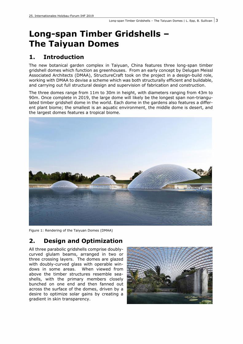
The new botanical garden complex in Taiyuan, China features three long-span timber
gridshell domes which function as greenhouses. From an early concept by Delugan Meissl Associated Architects (DMAA), StructureCraft took on the project in a design-build role,
working with DMAA to devise a scheme which was both structurally efficient and buildable, and carrying out full structural design and supervision of fabrication and construction.
The three domes range from 11m to 30m in height, with diameters ranging from 43m to 90m. Once complete in 2019, the large dome will likely be the longest span non-triangu-
lated timber gridshell dome in the world. Each dome in the gardens also features a differ-ent plant biome; the smallest is an aquatic environment, the middle dome is desert, and
the largest domes features a tropical biome.
Figure 1: Rendering of the Taiyuan Domes (DMAA)
2. Design and Optimization
All three parabolic gridshells comprise doubly-
curved glulam beams, arranged in two or three crossing layers. The domes are glazed
with doubly-curved glass with operable win-dows in some areas. When viewed from
above the timber structures resemble sea-
shells, with the primary members closely bunched on one end and then fanned out
across the surface of the domes, driven by a desire to optimize solar gains by creating a
gradient in skin transparency.
25. Internationales Holzbau-Forum IHF 2019
Long-span Timber Gridshells – The Taiyuan Domes | L. Epp, B. Sullivan
4
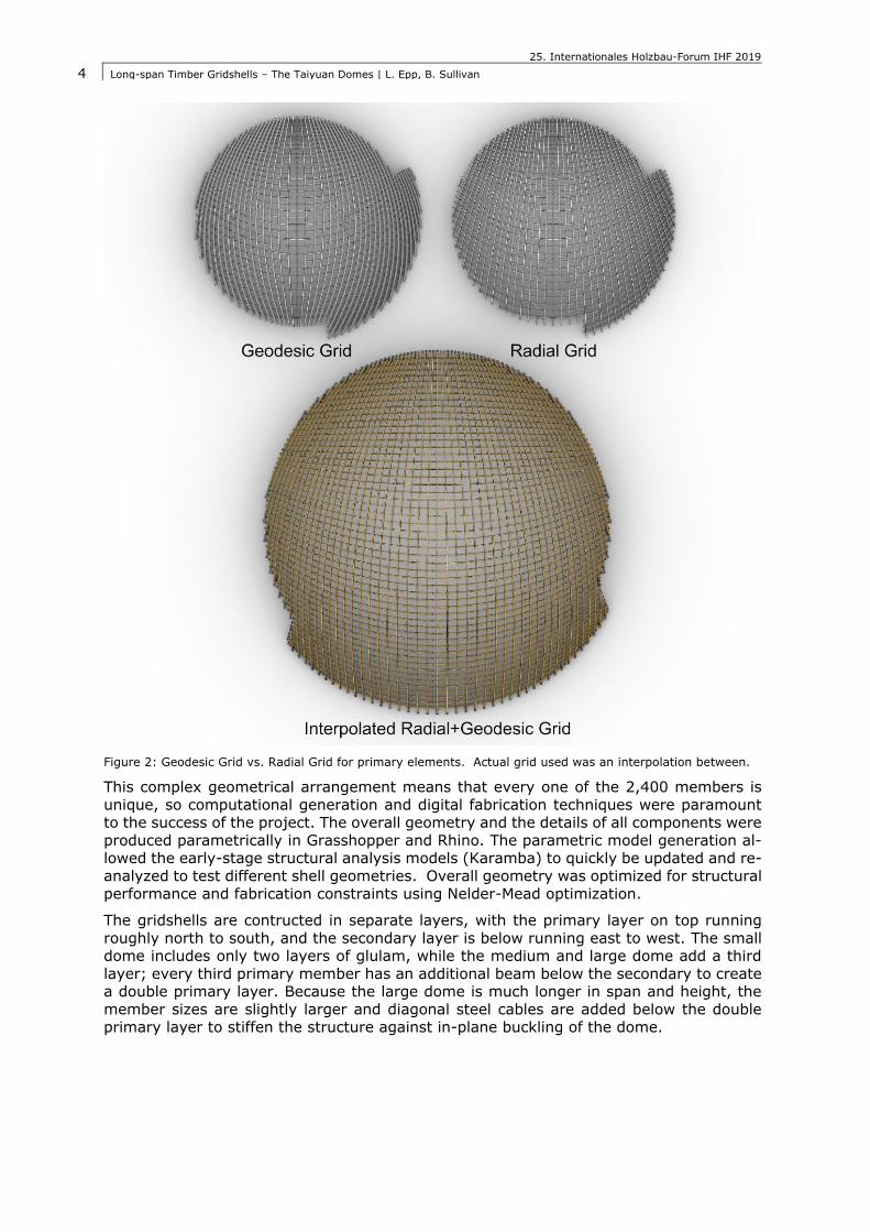
Figure 2: Geodesic Grid vs. Radial Grid for primary elements. Actual grid used was an interpolation between.
This complex geometrical arrangement means that every one of the 2,400 members is
unique, so computational generation and digital fabrication techniques were paramount to the success of the project. The overall geometry and the details of all components were
produced parametrically in Grasshopper and Rhino. The parametric model generation al-lowed the early-stage structural analysis models (Karamba) to quickly be updated and re-
analyzed to test different shell geometries. Overall geometry was optimized for structural
performance and fabrication constraints using Nelder-Mead optimization.
The gridshells are contructed in separate layers, with the primary layer on top running
roughly north to south, and the secondary layer is below running east to west. The small dome includes only two layers of glulam, while the medium and large dome add a third
layer; every third primary member has an additional beam below the secondary to create a double primary layer. Because the large dome is much longer in span and height, the
member sizes are slightly larger and diagonal steel cables are added below the double primary layer to stiffen the structure against in-plane buckling of the dome.
25. Internationales Holzbau-Forum IHF 2019
Long-span Timber Gridshells – The Taiyuan Domes | L. Epp, B. Sullivan
5
Figure 3: Typical gridshell cross section showing the three layers of the large dome
2.1. Member Orientation
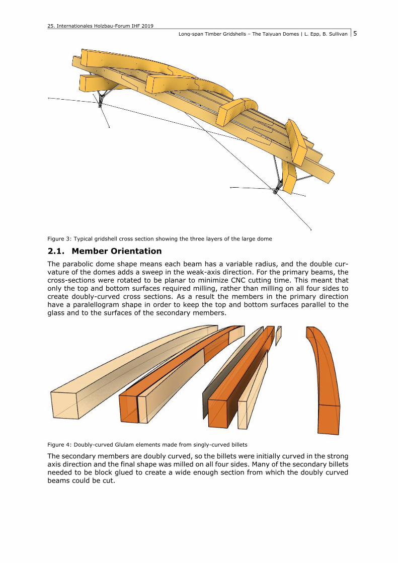
The parabolic dome shape means each beam has a variable radius, and the double cur-
vature of the domes adds a sweep in the weak-axis direction. For the primary beams, the cross-sections were rotated to be planar to minimize CNC cutting time. This meant that
only the top and bottom surfaces required milling, rather than milling on all four sides to
create doubly-curved cross sections. As a result the members in the primary direction have a paralellogram shape in order to keep the top and bottom surfaces parallel to the
glass and to the surfaces of the secondary members.
Figure 4: Doubly-curved Glulam elements made from singly-curved billets
The secondary members are doubly curved, so the billets were initially curved in the strong
axis direction and the final shape was milled on all four sides. Many of the secondary billets needed to be block glued to create a wide enough section from which the doubly curved
beams could be cut.
25. Internationales Holzbau-Forum IHF 2019
Long-span Timber Gridshells – The Taiyuan Domes | L. Epp, B. Sullivan
6
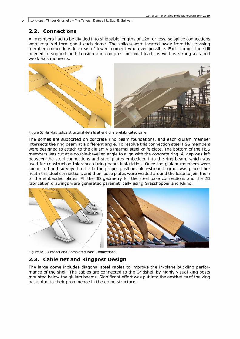
2.2. Connections
All members had to be divided into shippable lengths of 12m or less, so splice connections
were required throughout each dome. The splices were located away from the crossing member connections in areas of lower moment wherever possible. Each connection still
needed to support both tension and compression axial load, as well as strong-axis and
weak axis moments.
Figure 5: Half-lap splice structural details at end of a prefabricated panel
The domes are supported on concrete ring beam foundations, and each glulam member
intersects the ring beam at a different angle. To resolve this connection steel HSS members were designed to attach to the glulam via internal steel knife plate. The bottom of the HSS
members was cut at a double-bevelled angle to align with the concrete ring. A gap was left between the steel connections and steel plates embedded into the ring beam, which was
used for construction tolerance during panel installation. Once the glulam members were connected and surveyed to be in the proper position, high-strength grout was placed be-
neath the steel connections and then loose plates were welded around the base to join them
to the embedded plates. All the 3D geometry for the steel base connections and the 2D
fabrication drawings were generated parametrically using Grasshopper and Rhino.
Figure 6: 3D model and Completed Base Connections
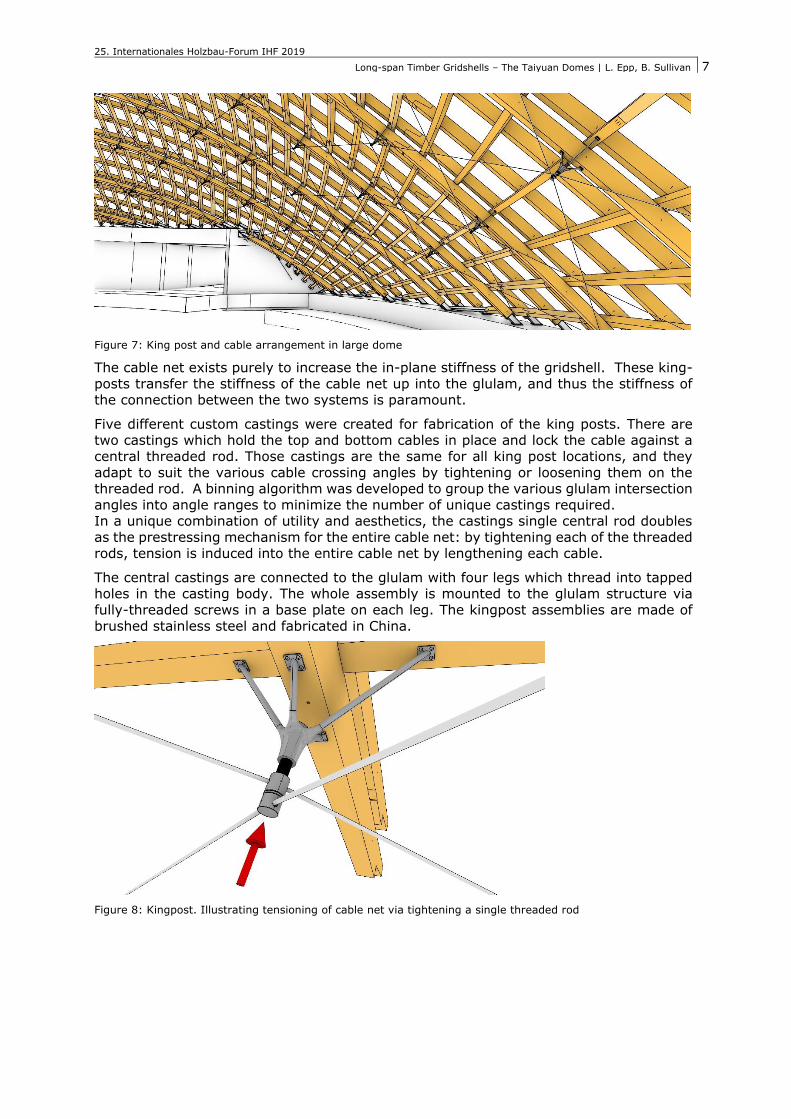
2.3. Cable net and Kingpost Design
The large dome includes diagonal steel cables to improve the in-plane buckling perfor-
mance of the shell. The cables are connected to the Gridshell by highly visual king posts
mounted below the glulam beams. Significant effort was put into the aesthetics of the king
posts due to their prominence in the dome structure.
25. Internationales Holzbau-Forum IHF 2019
Long-span Timber Gridshells – The Taiyuan Domes | L. Epp, B. Sullivan
7
Figure 7: King post and cable arrangement in large dome
The cable net exists purely to increase the in-plane stiffness of the gridshell. These king-
posts transfer the stiffness of the cable net up into the glulam, and thus the stiffness of the connection between the two systems is paramount.
Five different custom castings were created for fabrication of the king posts. There are two castings which hold the top and bottom cables in place and lock the cable against a
central threaded rod. Those castings are the same for all king post locations, and they
adapt to suit the various cable crossing angles by tightening or loosening them on the threaded rod. A binning algorithm was developed to group the various glulam intersection
angles into angle ranges to minimize the number of unique castings required. In a unique combination of utility and aesthetics, the castings single central rod doubles
as the prestressing mechanism for the entire cable net: by tightening each of the threaded rods, tension is induced into the entire cable net by lengthening each cable.
The central castings are connected to the glulam with four legs which thread into tapped holes in the casting body. The whole assembly is mounted to the glulam structure via
fully-threaded screws in a base plate on each leg. The kingpost assemblies are made of
brushed stainless steel and fabricated in China.
Figure 8: Kingpost. Illustrating tensioning of cable net via tightening a single threaded rod
25. Internationales Holzbau-Forum IHF 2019
Long-span Timber Gridshells – The Taiyuan Domes | L. Epp, B. Sullivan
8
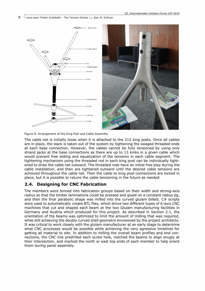
Figure 9: Arrangement of the King Post and Cable Assembly
The cable net is initially loose when it is attached to the 212 king posts. Once all cables
are in place, the slack is taken out of the system by tightening the swaged threaded ends at each base connection. However, the cables cannot be fully tensioned by using only
strand jacks at the base connections as there are up to 13 kinks in a given cable which would prevent free sliding and equalization of the tensions in each cable segment. The
tightening mechanism using the threaded rod in each king post can be individually tight-
ened to draw the cable net outward. The threaded rods have an initial free play during the cable installation, and then are tightened outward until the desired cable tensions are
achieved throughout the cable net. Then the cable to king post connections are locked in place, but it is possible to retune the cable tensioning in the future as needed.
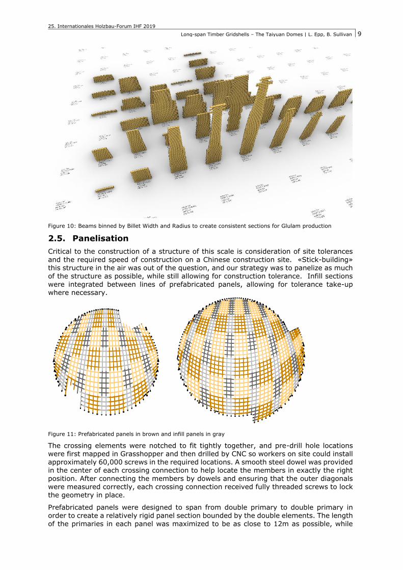
2.4. Designing for CNC Fabrication
The members were binned into fabrication groups based on their width and strong-axis radius so that the timber laminations could be pressed and glued on a constant radius jig,
and then the final parabolic shape was milled into the curved glulam billets. C# scripts
were used to automatically create BTL files, which drove two different types of 6-axis CNC machines that cut and shaped each beam at the two Glulam manufacturing facilities in
Germany and Austria which produced for this project. As described in Section 2.1, the orientation of the beams was optimized to limit the amount of milling that was required,
while still achieving the doubly curved shell geometry envisioned by the project architects. It was critical to work closely with the glulam manufacturer at an early stage to determine
what CNC processes would be possible while achieving the very agressive timelines for getting all material to site. In addition to milling the overall beam profiles and end con-
nections, the CNC line predrilled each screw hole, notched the beams to align snugly at
their intersection, and marked the north or east top ends of each member to help orient them during panel assembly.
25. Internationales Holzbau-Forum IHF 2019
Long-span Timber Gridshells – The Taiyuan Domes | L. Epp, B. Sullivan
9
Figure 10: Beams binned by Billet Width and Radius to create consistent sections for Glulam production
2.5. Panelisation
Critical to the construction of a structure of this scale is consideration of site tolerances
and the required speed of construction on a Chinese construction site. «Stick-building» this structure in the air was out of the question, and our strategy was to panelize as much
of the structure as possible, while still allowing for construction tolerance. Infill sections
were integrated between lines of prefabricated panels, allowing for tolerance take-up where necessary.
Figure 11: Prefabricated panels in brown and infill panels in gray
The crossing elements were notched to fit tightly together, and pre-drill hole locations were first mapped in Grasshopper and then drilled by CNC so workers on site could install
approximately 60,000 screws in the required locations. A smooth steel dowel was provided in the center of each crossing connection to help locate the members in exactly the right
position. After connecting the members by dowels and ensuring that the outer diagonals were measured correctly, each crossing connection received fully threaded screws to lock
the geometry in place.
Prefabricated panels were designed to span from double primary to double primary in order to create a relatively rigid panel section bounded by the double elements. The length
of the primaries in each panel was maximized to be as close to 12m as possible, while
25. Internationales Holzbau-Forum IHF 2019
Long-span Timber Gridshells – The Taiyuan Domes | L. Epp, B. Sullivan
10
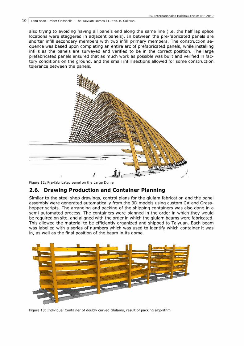
also trying to avoiding having all panels end along the same line (i.e. the half lap splice
locations were staggered in adjacent panels). In between the pre-fabricated panels are shorter infill secondary members with two infill primary members. The construction se-
quence was based upon completing an entire arc of prefabricated panels, while installing infills as the panels are surveyed and verified to be in the correct position. The large
prefabricated panels ensured that as much work as possible was built and verified in fac-
tory conditions on the ground, and the small infill sections allowed for some construction tolerance between the panels.
Figure 12: Pre-fabricated panel on the Large Dome
2.6. Drawing Production and Container Planning
Similar to the steel shop drawings, control plans for the glulam fabrication and the panel
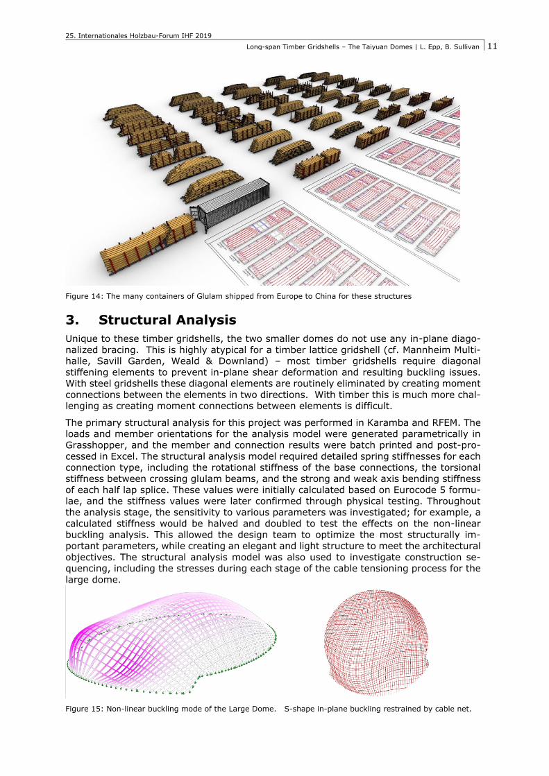
assembly were generated automatically from the 3D models using custom C# and Grass-hopper scripts. The arranging and packing of the shipping containers was also done in a
semi-automated process. The containers were planned in the order in which they would
be required on site, and aligned with the order in which the glulam beams were fabricated. This allowed the material to be efficiently organized and shipped to Taiyuan. Each beam
was labelled with a series of numbers which was used to identify which container it was in, as well as the final position of the beam in its dome.
Figure 13: Individual Container of doubly curved Glulams, result of packing algorithm
25. Internationales Holzbau-Forum IHF 2019
Long-span Timber Gridshells – The Taiyuan Domes | L. Epp, B. Sullivan
11
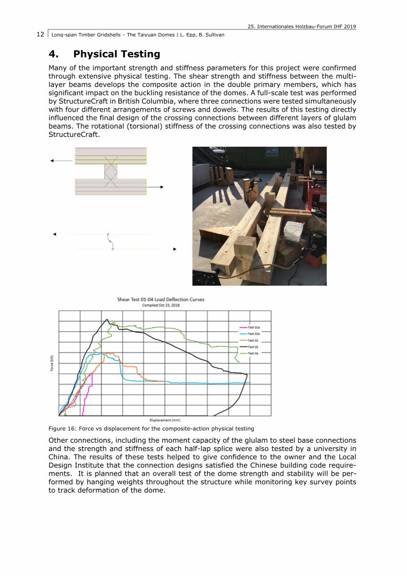
Figure 14: The many containers of Glulam shipped from Europe to China for these structures
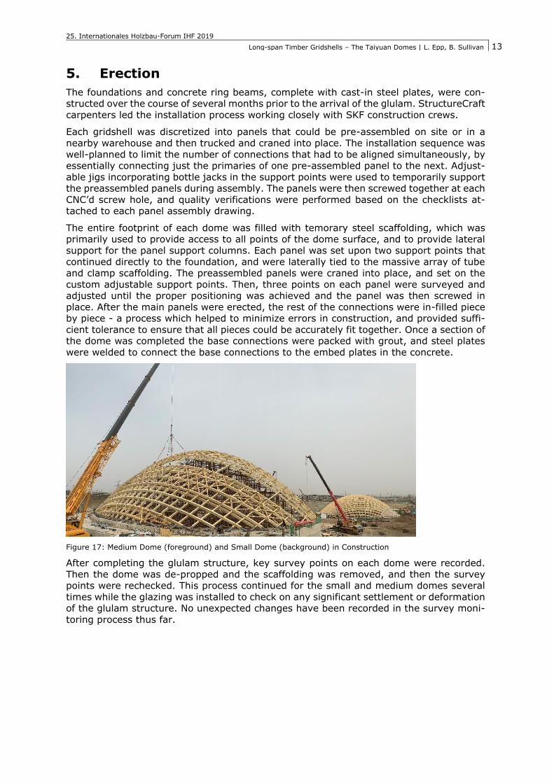
3. Structural Analysis
Unique to these timber gridshells, the two smaller domes do not use any in-plane diago-
nalized bracing. This is highly atypical for a timber lattice gridshell (cf. Mannheim Multi-halle, Savill Garden, Weald & Downland) – most timber gridshells require diagonal
stiffening elements to prevent in-plane shear deformation and resulting buckling issues. With steel gridshells these diagonal elements are routinely eliminated by creating moment
connections between the elements in two directions. With timber this is much more chal-lenging as creating moment connections between elements is difficult.
The primary structural analysis for this project was performed in Karamba and RFEM. The loads and member orientations for the analysis model were generated parametrically in
Grasshopper, and the member and connection results were batch printed and post-pro-
cessed in Excel. The structural analysis model required detailed spring stiffnesses for each connection type, including the rotational stiffness of the base connections, the torsional
stiffness between crossing glulam beams, and the strong and weak axis bending stiffness of each half lap splice. These values were initially calculated based on Eurocode 5 formu-
lae, and the stiffness values were later confirmed through physical testing. Throughout the analysis stage, the sensitivity to various parameters was investigated; for example, a
calculated stiffness would be halved and doubled to test the effects on the non-linear buckling analysis. This allowed the design team to optimize the most structurally im-
portant parameters, while creating an elegant and light structure to meet the architectural
objectives. The structural analysis model was also used to investigate construction se-quencing, including the stresses during each stage of the cable tensioning process for the
large dome.
Figure 15: Non-linear buckling mode of the Large Dome. S-shape in-plane buckling restrained by cable net.
25. Internationales Holzbau-Forum IHF 2019
Long-span Timber Gridshells – The Taiyuan Domes | L. Epp, B. Sullivan
12
4. Physical Testing
Many of the important strength and stiffness parameters for this project were confirmed through extensive physical testing. The shear strength and stiffness between the multi-
layer beams develops the composite action in the double primary members, which has significant impact on the buckling resistance of the domes. A full-scale test was performed
by StructureCraft in British Columbia, where three connections were tested simultaneously
with four different arrangements of screws and dowels. The results of this testing directly influenced the final design of the crossing connections between different layers of glulam
beams. The rotational (torsional) stiffness of the crossing connections was also tested by StructureCraft.
Figure 16: Force vs displacement for the composite-action physical testing
Other connections, including the moment capacity of the glulam to steel base connections
and the strength and stiffness of each half-lap splice were also tested by a university in China. The results of these tests helped to give confidence to the owner and the Local
Design Institute that the connection designs satisfied the Chinese building code require-ments. It is planned that an overall test of the dome strength and stability will be per-
formed by hanging weights throughout the structure while monitoring key survey points to track deformation of the dome.
25. Internationales Holzbau-Forum IHF 2019
Long-span Timber Gridshells – The Taiyuan Domes | L. Epp, B. Sullivan
13
5. Erection
The foundations and concrete ring beams, complete with cast-in steel plates, were con-structed over the course of several months prior to the arrival of the glulam. StructureCraft
carpenters led the installation process working closely with SKF construction crews.
Each gridshell was discretized into panels that could be pre-assembled on site or in a
nearby warehouse and then trucked and craned into place. The installation sequence was
well-planned to limit the number of connections that had to be aligned simultaneously, by essentially connecting just the primaries of one pre-assembled panel to the next. Adjust-
able jigs incorporating bottle jacks in the support points were used to temporarily support the preassembled panels during assembly. The panels were then screwed together at each
CNC’d screw hole, and quality verifications were performed based on the checklists at-tached to each panel assembly drawing.
The entire footprint of each dome was filled with temorary steel scaffolding, which was primarily used to provide access to all points of the dome surface, and to provide lateral
support for the panel support columns. Each panel was set upon two support points that
continued directly to the foundation, and were laterally tied to the massive array of tube and clamp scaffolding. The preassembled panels were craned into place, and set on the
custom adjustable support points. Then, three points on each panel were surveyed and adjusted until the proper positioning was achieved and the panel was then screwed in
place. After the main panels were erected, the rest of the connections were in-filled piece by piece - a process which helped to minimize errors in construction, and provided suffi-
cient tolerance to ensure that all pieces could be accurately fit together. Once a section of the dome was completed the base connections were packed with grout, and steel plates
were welded to connect the base connections to the embed plates in the concrete.
Figure 17: Medium Dome (foreground) and Small Dome (background) in Construction
After completing the glulam structure, key survey points on each dome were recorded.
Then the dome was de-propped and the scaffolding was removed, and then the survey points were rechecked. This process continued for the small and medium domes several
times while the glazing was installed to check on any significant settlement or deformation of the glulam structure. No unexpected changes have been recorded in the survey moni-
toring process thus far.
25. Internationales Holzbau-Forum IHF 2019
Long-span Timber Gridshells – The Taiyuan Domes | L. Epp, B. Sullivan
14
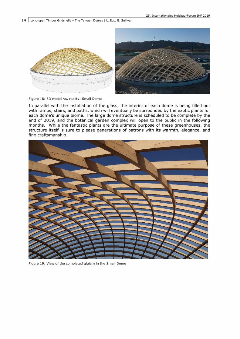
Figure 18: 3D model vs. reality: Small Dome
In parallel with the installation of the glass, the interior of each dome is being filled out with ramps, stairs, and paths, which will eventually be surrounded by the exotic plants for
each dome’s unique biome. The large dome structure is scheduled to be complete by the
end of 2019, and the botanical garden complex will open to the public in the following months. While the fantastic plants are the ultimate purpose of these greenhouses, the
structure itself is sure to please generations of patrons with its warmth, elegance, and
fine craftsmanship.
Figure 19: View of the completed glulam in the Small Dome
25. Internationales Holzbau-Forum IHF 2019
Long-span Timber Gridshells – The Taiyuan Domes | L. Epp, B. Sullivan
15
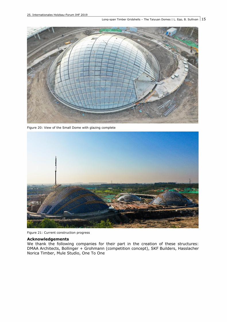
Figure 20: View of the Small Dome with glazing complete
Figure 21: Current construction progress
Acknowledgements
We thank the following companies for their part in the creation of these structures: DMAA Architects, Bollinger + Grohmann (competition concept), SKF Builders, Hasslacher
Norica Timber, Mule Studio, One To One