form finding in elastic gridshells · 2018-01-12 · engineering form finding in elastic...
TRANSCRIPT
ENG
INEE
RIN
G
Form finding in elastic gridshellsChangyeob Baeka,1, Andrew O. Sageman-Furnasb,1, Mohammad K. Jaweda, and Pedro M. Reisa,c,d,2
aDepartment of Mechanical Engineering, Massachusetts Institute of Technology, Cambridge, MA 02139; bInstitute for Numerical and Applied Mathematics,University of Goettingen, 37073 Goettingen, Germany; cDepartment of Civil and Environmental Engineering, Massachusetts Institute of Technology,Cambridge, MA 02139; and dFlexible Structures Laboratory, Ecole Polytechnique Federale de Lausanne, Lausanne CH-1015, Switzerland
Edited by David A. Weitz, Harvard University, Cambridge, MA, and approved November 20, 2017 (received for review August 4, 2017)
Elastic gridshells comprise an initially planar network of elasticrods that are actuated into a shell-like structure by loading theirextremities. The resulting actuated form derives from the elasticbuckling of the rods subjected to inextensibility. We study elasticgridshells with a focus on the rational design of the final shapes.Our precision desktop experiments exhibit complex geometries,even from seemingly simple initial configurations and actuationprocesses. The numerical simulations capture this nonintuitivebehavior with excellent quantitative agreement, allowing for anexploration of parameter space that reveals multistable states.We then turn to the theory of smooth Chebyshev nets to addressthe inverse design of hemispherical elastic gridshells. The resultssuggest that rod inextensibility, not elastic response, dictates thezeroth-order shape of an actuated elastic gridshell. As it turns out,this is the shape of a common household strainer. Therefore, thegeometry of Chebyshev nets can be further used to understandelastic gridshells. In particular, we introduce a way to quantify theintrinsic shape of the empty, but enclosed regions, which we thenuse to rationalize the nonlocal deformation of elastic gridshells topoint loading. This justifies the observed difficulty in form find-ing. Nevertheless, we close with an exploration of concatenatingmultiple elastic gridshell building blocks.
elastic structures | gridshells | buckling | Chebyshev nets | mechanicalinstabilities
Camping tents create curved shell-like structures in threedimensions (3D) through elastic buckling of a network of
rods. In the 1970s, the architectural community transferred thisidea into the realm of large-scale construction (1) by introducingthe concept of an elastic gridshell, a regular grid of elastic rodsthat is actuated into a shell-like structure by loading its extrem-ities. Research has since focused mostly on case studies (1–3)and computational form finding of the static actuated geome-try (4–6). Elastic gridshells fit with the recent trend in extrememechanics to design through buckling, by harnessing the under-lying geometry (7, 8). Examples of these geometry-driven struc-tures range from microscopic buckling of a series of ribbonsattached to a prestretched substrate (9) to macroscopic origami-inspired engineering (10, 11).
The buckled forms of elastic gridshells (Fig. 1A) suggest a non-trivial functional relationship between the initially flat, regulargrid and the ensuing actuated geometry, making both forwardand inverse design challenging tasks. This relationship juxtaposesrod elasticity and inextensibility, which are well understood in1D as classical Euler’s elastica (12), with a network of 2D con-straints that oversee the emergence of a shell-like structure. Thisnetwork can be modeled, on the one hand, from the perspectiveof interacting constrained elastica (13–15), an approach that iscommon in the study of random 3D polymer systems (16), butnot as well explored for structured 2D networks. On the otherhand, an elastic network can be modeled as a continuum of inex-tensible rods subjected to bending or shearing (17–20), whichresults in Euler–Lagrange equations but whose tractable solu-tions are often restricted to a plane or particular simple geome-tries. Instead of the variational approach, one can encode anelastic grid as a purely geometric object using the differentialgeometry of surfaces (21). This approach was taken by P. L.
Chebyshev in the 1880s (22) while investigating the deformationsof woven fabric. The resulting theory of smooth Chebyshev netsis an ongoing topic of research which is one of the central themesof our study.
Here, we combine both perspectives of an elastic gridshell asan ensemble of constrained elastica and a continuum of inexten-sible rods to provide a quantitative description of their behav-ior. We focus on rationalizing the design challenges that under-lie the actuation process and the resulting shape. Our physicalmodel implements a 2D network of inextensible elastic rods ina desktop-scale setting that allows for high-precision validationagainst numerical simulations and theory. For simulations, weextend the discrete elastic rod (DER) method (23, 24) to elasticgridshells. We find excellent agreement with experiments (Fig.1), allowing us to explore the parameter space of a seeminglysimple elastic gridshell. This exploration reveals the complexityof actuation and forward design, as well as the presence of multi-stability. We then interpret elastic gridshells as both a network ofsmooth rods and a continuum by finitely sampling a Chebyshevnet. This perspective enables an inverse design process, whoseresults suggest that rod inextensibility—not elasticity—is primaryin dictating the zeroth-order shape of an actuated elastic grid-shell. Moreover, our combined perspective allows us to harnesstheorems about smooth Chebyshev nets to rationalize elasticgridshell shape. This leads to quantitative investigations of theirnonlocal response to loading and provides justification of thedifficulties in form finding. We, therefore, expose the geometry-driven nature of elastic gridshells.
Significance
Elastic gridshells arise from the buckling of an initially pla-nar grid of rods. The interaction of elasticity and geomet-ric constraints makes their actuated shapes difficult to pre-dict using classical methods. However, recent progress inextreme mechanics reveals the benefits of structures thatbuckle by design, when exploiting underlying geometry. Here,we demonstrate the geometry-driven nature of elastic grid-shells. We use a geometric model, originally for woven fabric,to rationalize their actuated shapes and describe their non-local response to loading. Validation is provided with preci-sion experiments and rod-based simulations. The prominenceof geometry in elastic gridshells that we identify should allowfor our results to transfer across length scales from architec-tural structures to micro/nano–1-df mechanical actuators andself-assembly systems.
Author contributions: A.O.S.-F. and P.M.R. designed research; C.B., A.O.S.-F., and P.M.R.performed research; C.B., A.O.S.-F., M.K.J., and P.M.R. contributed new reagents/analytictools; C.B. and A.O.S.-F. analyzed data; and C.B., A.O.S.-F., and P.M.R. wrote thepaper.
The authors declare no conflict of interest.
This article is a PNAS Direct Submission.
Published under the PNAS license.1C.B. and A.O.S.-F. contributed equally to this work.2To whom correspondence should be addressed. Email: [email protected].
This article contains supporting information online at www.pnas.org/lookup/suppl/doi:10.1073/pnas.1713841115/-/DCSupplemental.
www.pnas.org/cgi/doi/10.1073/pnas.1713841115 PNAS | January 2, 2018 | vol. 115 | no. 1 | 75–80

A1 A2 A3
B3B2B1
Fig. 1. (A and B) Actuation of an elastic gridshell from (A) experimentsand (B) DER simulation. The edge points of a planar and unloaded foot-print (A1 and B1) are gradually moved toward a prescribed actuatedboundary (A2 and B2) to yield an actuated shape (A3 and B3). (Scale bar,20 mm.)
Anatomy and Actuation of an Elastic GridshellOur model system comprises a planar, completely unloaded foot-print of elastic rods that is actuated by loading its extremities(Fig. 1 A1). A footprint is constructed from straight elastic rodsthat are assumed to be inextensible (Materials and Methods).First, two sets of parallel rods with spacing d are laid perpen-dicularly. Then, the points of contact between cross-laid rods areconstrained by joints. A square grid results, where each emptyunit cell is enclosed by four adjacent rod segments of length d .Finally, the square grid is cut along an original boundary thatencloses the footprint. A footprint thus contains a region ofsquare grid and a boundary layer of “legs” extending to edgepoints along the original boundary. Pinning these edge pointsonto an actuated boundary of smaller perimeter induces out-of-plane buckling. The ensuing 3D actuated form is dictated by acombination of the elastic deformation of the rods and the geo-metric constraints of the grid. Without joints, each rod wouldact as an independent Euler’s elastica (12). Instead, the systembehaves as a shell-like structure, whose shape, in contrast to acontinuum shell, must be rationalized by resolving its actuatedunit cells. We explored the form finding of elastic gridshells,using precision desktop-scale experiments (Materials and Meth-ods). Elastomeric joints enforce positional constraints betweencross-laid Nitinol rods, with negligible resistance to both shear ofthe unit cells and transport of twist along each rod. The super-elastic nature of Nitinol ensures that the gridshell remains elas-tic throughout actuation. Pinned boundary conditions at the edgepoints are set by 3D-printed ball joints, which, for actuation, weremanually fitted onto a series of laser-cut holes on the designatedactuated boundary (Fig. 1A).
ExperimentDER
x/R01.0
0y/R
0
0.8z/R
x/R01.0
0y/R
00.8
z/RA2 A3A1
1.0
2.0
3.0
4.0
5 7 9 11 13 15Number of rods,
Nor
m. b
ound
ary
thic
knes
s,
C3
x/R 01.0
0y/R
00.8z/R
C1 C4C2
xy
xy
xy
xy
B
i ii iii iv
Fig. 2. Elastic gridshells with circular boundaries. (A) Multistable states of a circular elastic gridshell with (Ld, n) = (0.8, 12) observed from experiments(red solid circles) and simulations (black lines). (B) Phase diagram of elastic gridshells with circular boundaries. In addition to the three states in A, a convexdome-shaped state (B, Inset) is obtained by extending the legs. Each data point is obtained from DER simulations under a jittering procedure. (C) Fourrepresentative modes of the circular elastic gridshells with different symmetry properties.
In parallel to the experiments, we performed numerical simu-lations using the DER method, which was originally developedin the computer graphics community for the realistic visualiza-tion of filamentous structures such as hair and fur (23, 24). Morerecently, DER has been shown to be remarkably predictive inengineering contexts to quantify large deformations of elasticrods (25). Our current implementation of DER simulates elas-tic gridshells using rods under Kirchhoff’s assumptions, with thesame physical parameters as in experiments. The positional con-straints imposed by joints are modeled by stiff effective springs(Materials and Methods).
In Fig. 1 and Movie S1, we show representative examples,from both physical experiments (Fig. 1 A1–A3) and numeri-cal simulations (Fig. 1 B1–B3), of a footprint with a circularoriginal boundary, with radius Ro =126.0mm, that was grad-ually compressed to circular actuated boundaries with radiiRa [mm] = {126.0, 115.9, 94.5}. Excellent qualitative agreementis found between the two. As the actuation progresses, the heightof the midsection increases and a dome-shaped gridshell emerges.We also consider noncircular boundaries.
Elastic Gridshells with Circular BoundariesEven though the original and actuated boundaries in the exam-ple of Fig. 1 were both circular, the resulting actuated geome-tries were surprisingly complex (we expected to find entirely con-cave domes). This behavior is a signature of higher-order modes,which are known to arise in the theory of constrained elastica(13–15), and suggests the presence of multistability. Moreover,these complex geometries point to a nontrivial functional rela-tionship between footprints and their actuated forms, which weaddress next.
In Fig. 2 A1–A3, we show three multistable states of thesame elastic gridshell, in both experiment and simulation. Theexperimental state is represented by the positions of its joints(red solid circles) acquired via 3D laser scanning (Materialsand Methods) and was obtained by manually point loadingthe actuated form and allowing it to snap into a new state.The corresponding multistable numerical solutions (solid lines)were computed by a jittering algorithm (Materials and Meth-ods) and are in excellent quantitative agreement with experi-ments; the maximum joint positional mismatch is within twojoint radii.
Given the accurate predictions from our simulations, we nowrely on DER to systematically explore the parameter space ofelastic gridshells with circular boundaries. The radius of the actu-ated boundary is set to Ra =0.75Ro. To investigate boundarylayer effects, we consider the longest “leg” in a footprint withn rods per direction, normalized by its unit cell spacing d ; i.e.,Ld =
Ld= Ro
d− n−1
2. We further enforce Ld > 0 (otherwise, the
number of rods would reduce to n − 2). In Fig. 2B, we show the
76 | www.pnas.org/cgi/doi/10.1073/pnas.1713841115 Baek et al.

ENG
INEE
RIN
G
resulting phase diagram in the (Ld ,n) parameter space, whereeach footprint was actuated and subject to our jittering algo-rithm. We observe four qualitatively distinct states; examples areshown in Fig. 2 C1–C4. All footprints considered have four sym-metry planes (y = x , y =−x , x =0, and y =0). State i retains fullsymmetry and involves only first-order rod buckling, resulting inconcave domes. States ii and iii exhibit symmetry breaking andhigher-order buckling; state ii retains only two symmetry planeswhile state iii retains only 90◦ rotational symmetry. In contrast,state iv also involves higher-order buckling but retains full sym-metry.
We interpret the presence of multistability in Fig. 2B by con-sidering the normalized length of the shortest leg; i.e., �d = �
d=[(
Rod
)2 − (n−12
)2]1/2 − n−12
. When �d > 1, joints still constrainthe overall shape, but do not prevent all rods from exhibitingfirst-order buckling, and result in monostable concave domes.The onset of multistable states occurs for �d � 1. Note that, eventhough Ld ≥ 0, the quantity �d can be nonpositive. We observethat states iii and iv start to appear for �d ≈ 0, and they occur foralmost all possible configurations when �d � −1.
Even though we got concave domes by increasing the footprintlegs, the ensuing geometries were not hemispherical despite hav-ing circular boundaries. How can one obtain a hemisphericalgridshell? Can we better understand the anisotropy induced byrod inextensibility?
Hemispherical Elastic Gridshells from Chebyshev NetsIn Fig. 3A, we show an experimental gridshell with �2% point-wise deviation from a hemisphere. The original boundary ofits footprint is a rounded diamond (Fig. 3B, outermost curve).Recall from above that, by contrast, circular original boundariesproduced complex, multistable geometries (Fig. 2A). We demon-strate how the continuum theory of Chebyshev nets (22, 26) canbe used to rationally design and quantify the geometry of elas-tic gridshells, as in the example of Fig. 3A. Whereas a discreteanalog of Chebyshev nets [which approximates all rod segmentsbetween joints by straight lines of the same length (27)] has pre-viously been used for this class of problems (1, 5, 6), we empha-size the relationship to smooth Chebyshev nets. This perspectiveoffers three benefits for elastic gridshells: (i) a precise method toquantify the accuracy of the actuated forms vis-a-vis the originaltarget designs, (ii) a quantitative characterization of the geome-try at the level of the curved unit cells, and (iii) a rationale forthe nonlocal response to loading.
A Review of Chebyshev Nets. Before continuing with our ownwork, we provide a brief review of a smooth Chebyshev net,
A B C1
D
0
2E
C2 Chebyshev Hemisphere
ExperimentDER
x/R
-1.00
1.00
-1.0
y/R
0
1.0z/R
F
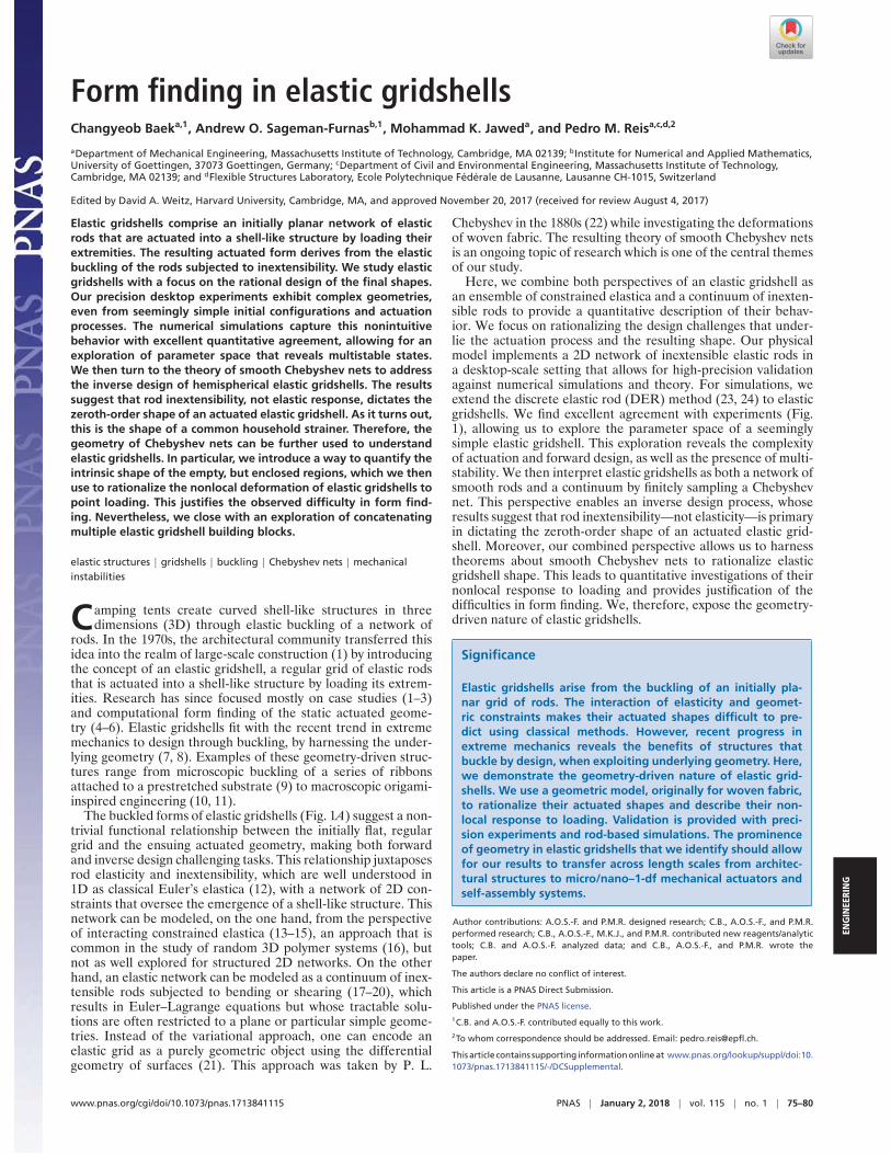
Fig. 3. Hemispherical elastic gridshells from Chebyshev’s hemisphere ansatz. (A) Photograph of a nearly hemispherical gridshell. (B) Boundary of thehemisphere domain (outermost contour) and spherical caps (five inner contours) obtained by cutting with planes (Inset). (C) Positions of the joints (redsolid circles; 3D scanning), along with the corresponding DER simulation (black solid lines) and the d-sampled Chebyshev net (blue solid lines). (D) Spherical-cap elastic gridshells obtained from DER simulations, whose footprints are shown in B. Colorbar represents deviation from the d-sampled Chebyshev netnormalized by the radius of the sphere, e =Δ/ρ. (E and F) A household strainer of z∗/ρ= 0.28 (E) and its flattened 2D domain (F), showing excellentagreement with a Chebyshev domain (solid line).
defined as a smooth parameterized surface patch C :D ⊂R2 →
R3, from a domain D in 2D with its orthogonal coordinate
system (u, v) to a smooth surface in 3D, under the condition‖∂C/∂u(u, v)‖ = ‖∂C/∂v(u, v)‖=1. Physically, this conditioncorresponds to inextensibility of the rods along the two initiallyperpendicular parameter directions. We regard C as the defor-mation of a continuum planar domain of inextensible rods intoa surface, during which crossing rods shear freely at joints. Theshear angle function 0 < ω(u, v) < π turns the unit tangentvector ∂C/∂u into ∂C/∂v .We focus on smooth Chebyshev netsthat do not have singularities; i.e., no rod collapses onto anotherwith ω ∈{0, π}.
A smooth Chebyshev net exists locally around each point of asurface (18, 28), but a global obstruction constraining the curva-ture arises from the necessary Gauss equation (21)
−K(u, v) sinω(u, v)=∂2
∂u∂vω(u, v), [1]
which enforces a strict coupling between shear and Gauss cur-vature, K(u, v). As rods shear, infinitesimal squares deform intorhombi, and the surface area element is dA = sinω dudv . Inte-grating Eq. 1 (with respect to u and v) over an axis-aligned rect-angle (denoted as �) yields a seminal result due to Hazzidakis(ref. 29; see also ref. 21): The integrated Gauss curvature ofeach deformed rectangle depends only on its four interior angles0 < αi < π,
∫C(�)
K(u, v)dA=2π −4∑
i=1
αi , [2]
so the maximum integrated Gauss curvature of every regionenclosed by four rods is 2π. Due to this inability to encoderegions with high curvature, finding a singularity-free smoothChebyshev net that lies on, or approximates to, an entire arbi-trary target shape is challenging and the topic of much ongoingtheoretical (30–34) and applied research (35–37). The key ideais to carefully design the domain, which translates into the foot-print of an elastic gridshell.
Footprint and Actuation Ansatzes from a Chebyshev Net. We usesmooth Chebyshev nets as educated guesses (ansatzes) for thedesign of elastic gridshells that provide solutions under the non-trivial inextensibility conditions, but neglect bending.
Formalizing an elastic gridshell, we define its footprint Fdb by
an enclosing original boundary b, which cuts an infinite squaregrid of spacing d . A correspondence g : b → a between positionsalong b and an actuated boundary a determines the location ofthe pinned edge points. The resulting actuated elastic gridshell
Baek et al. PNAS | January 2, 2018 | vol. 115 | no. 1 | 77
is represented by G: Fdb→ R
3. A specific Chebyshev net C isregarded as a viable ansatz if, for each position b ∈ b of the orig-inal boundary that maps to an actuated position a ∈ a, we haveC(b)= g(b)= a . Determining a viable ansatz for an elastic grid-shell involves three steps. First, we specify an actuated boundarya in the Chebyshev net surface. Second, we compute the origi-nal boundary in the domain by solving for the contour C(b)= a.Third, we fix d > 0 to determine the footprint Fd
b enclosed by b.Our ansatz procedure does not consider the pinned bound-
ary conditions on the actuated boundary, which lead to higher-order constraints from variational considerations of the bend-ing energy (19). Therefore, we quantify deviations, as follows,to attest the accuracy of viable Chebyshev net ansatzes. Wefirst restrict C to points of the footprint Fd
b (d sampling of theChebyshev net). Then, for each footprint point, x∈ Fd
b , wedefine Δ(x )= ‖C(x ) − G(x )‖, the pointwise distance betweenan actuated elastic gridshell and a d -sampled viable ansatz.
Elastic Gridshells That Resemble Spherical Caps. With the goal ofdesigning hemispherical and spherical-cap gridshells, we con-sider Chebyshev’s hemisphere Ch (22, 26, 38, 39) (see SIAppendix, S1. Hemispherical Ansatz for details on its construc-tion). We then use Ch as a viable ansatz by solving for the orig-inal boundary (shown as the outermost contour of Fig. 3B) thatcorresponds to an actuated boundary of the equator and fix-ing a unit cell spacing d =20 mm. This yields a footprint Fd
b ,which is then actuated into an elastic gridshell Gh . In Fig. 3 C1and C2, we quantify the deviation between the computed d sam-pling of Ch (blue curves) and the elastic gridshells correspondingto Gh obtained from both DER simulations (black curves) andexperiments (red solid circles). A visual comparison is shown inFig. 3 C1, while Fig. 3 C2 plots the data using spherical coor-dinates without longitudinal information (radius r , latitude φ);there is excellent agreement between theory, simulations, andexperiments. Hereafter, we compare a viable ansatz only with aDER actuated elastic gridshell. Quantitatively, we find that thereis �2% deviation between the d -sampled Ch and the DER elas-tic gridshell Gh (using Δ as introduced above).
To further affirm the strength of our ansatz protocol, we usethe same Ch to compute original boundaries of footprints forother spherical caps. Circles of latitude are used to slice thehemisphere by planes at varying heights (0 ≤ z∗/ρ < 1) andunderstood as actuated boundaries az∗ . Note that ρ is the fixedradius of the sphere and agrees with the radius of az∗ only whenz∗/ρ=0 (entire hemisphere). After fixing d =20 mm, the corre-sponding original boundaries bz∗ (Fig. 3B) yield a series of actu-ated elastic gridshells Gz∗ . In Fig. 3D, we quantify the result-ing deviations. As z∗/ρ increases, the deviation decreases from1.87% (z∗/ρ=0.3) to 0.17% (z∗/ρ=0.9). This agreement is sur-prising since the smaller footprints contain even fewer rods; acontinuum Chebyshev net ansatz may continue to be valid evenfor very coarse footprints within the limits of our inextensibilityassumptions, whose applicability is investigated in SI Appendix,S5. Inextensibility Limits of Elastic Gridshells. To emphasize thegeometric nature of these results, we considered a commonhousehold strainer (Fig. 3E), which also forms a spherical capfrom a network of plastic inextensible rods. Interestingly, itsflattened shape (after being cut along its “actuated boundary”rim) shows excellent agreement with a corresponding “originalboundary” from Ch (Fig. 3F), thereby pointing to the generalityof our framework.
Deformation of the Unit Cells and Nonlocal ResponseSuccess in deriving elastic gridshells from smooth Chebyshevnet ansatzes suggests broader applicability. We now use smoothChebyshev net theory to rationalize the shape of elastic grid-shells. In particular, we introduce a notion of integrated Gauss
curvature that relates directly to the shearing of the actuatedunit cells. Subsequently, we use this notion to explore the non-local and highly anisotropic response of elastic gridshell systemsunder point-load indentation.
Integrated Gauss Curvature per Unit Cell. Even though the surfaceof a unit cell is ill-defined, it does have well-defined crossingangles at its joints. Using Hazzidakis’ result, Eq. 2, for each unitcell of an actuated gridshell, we define its integrated Gauss curva-ture as K� =2π −∑4
i=1 αi . If the enclosing rods of an actuatedunit cell were to lie along geodesics, then the Gauss–Bonnet the-orem (21) would state that the integrated Gauss curvature of theenclosed region would be
∑4i=1 αi − 2π, exactly the negative of
our quantity K�. We will see that, generally, K� carries the signmatching our intuition, implying that we do not interpret elasticgridshell rods as lying along geodesics of an underlying surface.
Next, we evaluate the validity of the notion of integrated Gausscurvature, K�, to design and describe elastic gridshells. We studyviable ansatzes from surfaces of constant (i) positive, (ii) zero,and (iii) negative Gauss curvature, for which we use, respec-tively, (i) Chebyshev’s hemisphere Ch , (ii) half a circular cylinderparameterized by helices Cc , and (iii) half an analytic parameter-ization for a pseudosphere of revolution Cp . The latter two arespecial cases of Chebyshev nets on surfaces of revolution (40) (SIAppendix, S2. Cylindrical and Pseudospherical Ansatzes).
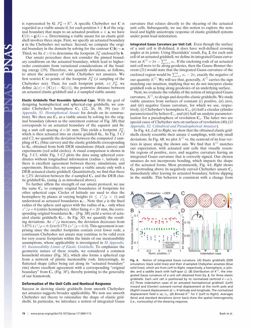
In Fig. 4A, Left to Right, we show that the obtained elastic grid-shells closely resemble their ansatz d samplings, with only smalldeviations. In Fig. 4B, we plot K� vs. the centroid of its four ver-tices in space along the shown axis. We find that K� matchesour expectation, with actuated unit cells that visually resem-ble regions of positive, zero, and negative curvature having anintegrated Gauss curvature that is correctly signed. Our chosenansatzes do not incorporate bending, which impacts the shapeof the actuated forms. Most prominently, Fig. 4A, Right showsGp protruding above its negatively curved Chebyshev ansatz Cp
immediately after leaving its actuated boundary, before dippingin the middle. This behavior is consistent with a change from
xy z
C
0
1
D
Norm. position, 0 0.5 1-0.5-1
0
0.1
-0.1
Int.
Gau
ssia
n C
urva
ture
,
A
HemisphereCylinderSaddle
xy z xyz
Chebyshev DER
0
0.10
0.05
Int.
Gau
ssia
n C
urva
ture
,
B
ReferenceIndentation case
Fig. 4. Notion of integrated Gauss curvature. (A) Elastic gridshells (DERsimulation; black solid lines) and their d-sampled Chebyshev ansatzes (bluesolid lines), which are from Left to Right, respectively, a hemisphere, a cylin-der, and a saddle (each with half-span L). (B) Distribution of K�, the inte-grated Gauss curvature of a unit cell obtained from Eq. 2, for three elasticgridshells. Each unit cell is positioned by its normalized centroid x = x/L.(C) Three indentation cases of an actuated hemispherical gridshell: (Left)inward and (Center) outward normal displacement at the north pole and(Right) inward displacement at π/4 latitude and longitude. The normalizeddisplacement field is |u|/δo. (D) Binned K� for C (Left to Right). Averages(bins) and standard deviations (error bars) show the spatial heterogeneity(i.e., nonlocality) of the shearing response.
78 | www.pnas.org/cgi/doi/10.1073/pnas.1713841115 Baek et al.

ENG
INEE
RIN
G
positive to negative curvature and is reflected in the distributionof K�, which derives from the actuated elastic gridshell itself,not a choice of viable ansatz.
We therefore find K� to be an excellent proxy for the curva-ture of actuated unit cells and its definition in terms of crossingangles at joints provides a way for us to rationalize the distribu-tion of shearing across an elastic gridshell.
Nonlocal Response to Point Loading. The quantity K� not onlydescribes the geometry of elastic gridshells, but also enables us tointerpret and quantify their nonlocal response under point loads.Given the hyperbolic nature of the underlying Gauss equation,Eq. 1, the rods can be regarded as characteristics, regularizedby bending energy, that act as “highways of deformation.” Assuch, we expect nonlocal behavior to be prevalent in elastic grid-shells. In contrast, similar loading of a thin isotropic continuumshell leads to a deformation that is local to a small spherical cap(41–43).
We subject an actuated hemispherical elastic gridshell Gh tothree types of point loading: (i and ii) inward (i) and outward (ii)normal displacement at the north pole and (iii) inward displace-ment at π/4 latitude and longitude. The magnitude of the inden-tation was chosen to be δo =0.1ρ. In Fig. 4C, we present the topview of these loaded elastic gridshells obtained with DER simula-tions and quantify the displacement from the unloaded, but actu-ated, state. Corresponding experimental elastic gridshells undermanual indentation are shown in Movie S2. The response for allthree loading cases of the hemispherical elastic gridshell is strik-ingly nonlocal. Case i introduces not only a local dimpled cap butalso displacements at the midpoints and corners of the largestconcentric curved rhombus, nearly reaching the boundary. Caseii causes the center pair of rods to approach their inextensibil-ity limits, forcing displacements to reach down to the equator.Case iii introduces displacement in a series of concentric curvedrhombi that span the system.
This nonlocal response can further be rationalized using K�.Movies S3–S5 present the time evolution of the spatial distribu-tion of K� for the above indentation cases i–iii. Each actuatedunit cell is segmented by the centroid of its vertices along the axisshown in Fig. 4A, Left (total length 2L). In Fig. 4D, as a snap-shot, we plot the spatial average of K� vs. bins of size 0.4/L.The SD within a bin measures the spatial heterogeneity of thecurvature carried by each quad. The unindented gridshell con-figuration is treated as reference. Upon indentation (in all threecases), the shear response is highly nonlocal, and the spatial dis-tribution of K� changes along its entire extent (Movies S3–S5).Interestingly, as indicated by horizontal lines in Movies S3–S5, thetotal integrated Gauss curvature (sum of all K�) remains con-stant throughout the indentation. This result reinforces that K�
is a valid reflection (beyond shearing) of integrated Gauss curva-ture. Moreover, a constant total K� establishes that nonlocalityin elastic gridshells is related to the regions enclosed by rods.
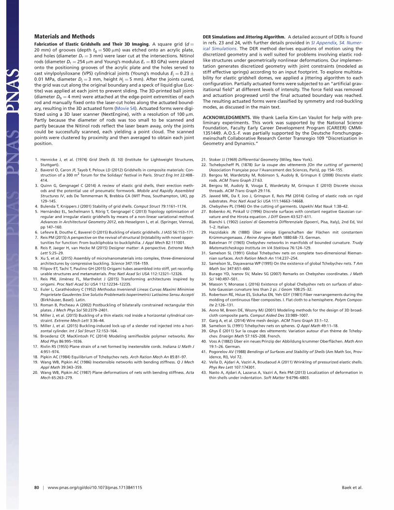
Assembling with Building BlocksFinally, we seek to assemble building blocks into more complexstructures. Our idea is to concatenate both individual footprintsand in-plane actuated boundaries, which reduces the task ofdirectly tackling a full target design. In Fig. 5 A1–A3, we presentthree examples of building blocks: a quarter-sphere, a cylinder,and a saddle. These building blocks are similar to the solutions inFig. 4A, but their footprints and corresponding actuated bound-aries have been strategically pruned at connection sites, wherecross-laid rods form a series of v-shaped notches. This pruningensures smooth assembly, with moderate deviation between therod positions and tangents. For example, we pruned the buildingblocks in Fig. 5 A1–A3 so that connection sites lie on half-circles
of similar radii, which also removed the saddle’s boundary rings(SI Appendix, S2. Cylindrical and Pseudospherical Ansatzes).
Two example geometries are targeted: a stadium (centralcylinder capped by quarter-spheres) and a peanut (central sad-dle capped by quarter-spheres). The concatenated footprints,together with their actuated boundaries, are provided in Fig.5 B1 and B2. The resulting actuated geometries are shown inFig. 5 C1 and C2, where the building blocks (colored lines)are superposed onto the actuated assemblage elastic gridshellsobtained from the DER (black lines). We find excellent qualita-tive agreement between building blocks and assemblages. In Fig.5D, we present an experimental peanut-shaped elastic gridshellobtained from the footprint in Fig. 5 B2. In Fig. 5E we overlay thedigitized experimental joint positions (red solid circles; Materialsand Methods) with the DER simulation (black solid lines), whichagain exhibit excellent agreement; the maximum joint positionalmismatch is within two joint radii.
ConclusionWe systematically explored elastic gridshells by combining the-ory with numerical and physical experiments. The design spaceof elastic gridshells with circular boundaries revealed a nontriv-ial relationship between flat and actuated geometries, as well asthe possibility of multistability. We then turned to the role ofinextensibility in the footprint design and created hemisphericalelastic gridshells from a Chebyshev ansatz. The excellent agree-ment between Chebyshev’s hemisphere and the resulting elasticgridshells motivated our further use of this theory. Using the for-mula of Hazzidakis, Eq. 2, we quantified the intrinsic shape of theempty unit cells. This justified the difficulty in bottom–up formfinding by providing a quantification of the nonlocal response ofelastic gridshells. Nevertheless, we briefly suggested an approachto more targeted design through elastic gridshell building blocks.
Our investigations revealed the geometry-driven nature ofelastic gridshells by merging the two perspectives of both an elas-tic gridshell as a finite network of elastic rods and a continuumof inextensible rods. This suggests that elastic gridshells, beyondtheir current use at the macroscale, may scale down to micro-or nanolength scales, where complex geometries arising fromsimple actuation have had exciting applications (9). In particu-lar, exploring 1-df actuation techniques may lead to new modesof self-assembly. Complementing these explorations, one canmove beyond our purely geometric treatment of elastic gridshellsand focus on their mechanical and scale-dependent aspects, e.g.,through the use of twist-transmitting joints, shear-resisting joints,or rods of nonlinear materials. The numerical framework weintroduced, together with its excellent agreement with experi-ments, provides a foundation from which to build.
B1 B2
C1 C2
HemisphereAssemblageCylinder
Saddle
A1
A2
A3
ExperimentDER Simulation
021
1
00
-1 -2
x/y/
z/
D
E
Fig. 5. Elastic gridshells from building blocks. (A) Pruned elastic grid-shell building blocks: (A1) hemisphere, (A2) cylinder, and (A3) saddle.(B and C) Comparison of concatenated elastic gridshell assemblage (blacksolid lines) and its building blocks (colored solid lines) for (B1 and C1) sta-dium (A1-A2-A1) and (B2 and C2) peanut (A1-A3-A1). (D) Photograph ofa peanut-shaped elastic gridshell. (E) Positions of the joints (red solid cir-cles; 3D scanning), along with the corresponding DER simulation (black solidlines).
Baek et al. PNAS | January 2, 2018 | vol. 115 | no. 1 | 79
Materials and MethodsFabrication of Elastic Gridshells and Their 3D Imaging. A square grid (d =
20 mm) of grooves (depth tg = 500 μm) was etched onto an acrylic plate,and holes (diameter Dr = 3 mm) were laser cut at the intersections. Nitinolrods (diameter Dr = 254 μm and Young’s modulus Er = 83 GPa) were placedonto the positioning grooves of the acrylic plate and the holes served tocast vinylpolysiloxane (VPS) cylindrical joints (Young’s modulus Ej = 0.23 ±0.01 MPa, diameter Dj = 3 mm, height Hj = 5 mm). After the joints cured,the grid was cut along the original boundary and a speck of liquid glue (Loc-tite) was applied at each joint to prevent sliding. The 3D-printed ball joints(diameter Db = 4 mm) were attached at the edge-point extremities of eachrod and manually fixed onto the laser-cut holes along the actuated bound-ary, resulting in the 3D actuated form (Movie S4). Actuated forms were digi-tized using a 3D laser scanner (NextEngine), with a resolution of 100 μm.Partly because the diameter of rods was too small to be scanned andpartly because the Nitinol rods reflect the laser beam away, only the jointscould be successfully scanned, each yielding a point cloud. The scannedpoints were clustered by proximity and then averaged to obtain each jointposition.
DER Simulations and Jittering Algorithm. A detailed account of DERs is foundin refs. 23 and 24, with further details provided in SI Appendix, S4. Numer-ical Simulations. The DER method derives equations of motion using thediscretized geometry and is well suited for problems involving elastic rod-like structures under geometrically nonlinear deformations. Our implemen-tation generates discretized geometry with joint constraints (modeled asstiff effective springs) according to an input footprint. To explore multista-bility for elastic gridshell domes, we applied a jittering algorithm to eachconfiguration. Partially actuated forms were subjected to an “artificial grav-itational field” at different levels of intensity. The force field was removedand actuation progressed until the final actuated boundary was reached.The resulting actuated forms were classified by symmetry and rod-bucklingmodes, as discussed in the main text.
ACKNOWLEDGMENTS. We thank Laelia Kim-Lan Vaulot for help with pre-liminary experiments. This work was supported by the National ScienceFoundation, Faculty Early Career Development Program (CAREER) CMMI-1351449. A.O.S.-F. was partially supported by the Deutsche Forschungsge-meinschaft Collaborative Research Center Transregio 109 “Discretization inGeometry and Dynamics.”
1. Hennicke J, et al. (1974) Grid Shells (IL 10) (Institute for Lightweight Structures,Stuttgart).
2. Baverel O, Caron JF, Tayeb F, Peloux LD (2012) Gridshells in composite materials: Con-struction of a 300 m2 forum for the Solidays’ festival in Paris. Struct Eng Int 22:408–414.
3. Quinn G, Gengnagel C (2014) A review of elastic grid shells, their erection meth-ods and the potential use of pneumatic formwork. Mobile and Rapidly AssembledStructures IV , eds De Temmerman N, Brebbia CA (WIT Press, Southampton, UK), pp129–145.
4. Bulenda T, Knippers J (2001) Stability of grid shells. Comput Struct 79:1161–1174.5. Hernandez EL, Sechelmann S, Rorig T, Gengnagel C (2013) Topology optimisation of
regular and irregular elastic gridshells by means of a non-linear variational method.Advances in Architectural Geometry 2012, eds Hesselgren L, et al. (Springer, Vienna),pp 147–160.
6. Lefevre B, Douthe C, Baverel O (2015) Buckling of elastic gridshells. J IASS 56:153–171.7. Reis PM (2015) A perspective on the revival of structural (In)stability with novel oppor-
tunities for function: From buckliphobia to buckliphilia. J Appl Mech 82:111001.8. Reis P, Jaeger H, van Hecke M (2015) Designer matter: A perspective. Extreme Mech
Lett 5:25–29.9. Xu S, et al. (2015) Assembly of micro/nanomaterials into complex, three-dimensional
architectures by compressive buckling. Science 347:154–159.10. Filipov ET, Tachi T, Paulino GH (2015) Origami tubes assembled into stiff, yet reconfig-
urable structures and metamaterials. Proc Natl Acad Sci USA 112:12321–12326.11. Reis PM, Jimenez FL, Marthelot J (2015) Transforming architectures inspired by
origami. Proc Natl Acad Sci USA 112:12234–12235.12. Euler L, Caratheodory C (1952) Methodus Inveniendi Lineas Curvas Maximi Minimive
Proprietate Gaudentes Sive Solutio Problematis Isoperimetrici Latissimo Sensu Accepti(Birkhauser, Basel). Latin.
13. Roman B, Pocheau A (2002) Postbuckling of bilaterally constrained rectangular thinplates. J Mech Phys Sol 50:2379–2401.
14. Miller J, et al. (2015) Buckling of a thin elastic rod inside a horizontal cylindrical con-straint. Extreme Mech Lett 3:36–44.
15. Miller J, et al. (2015) Buckling-induced lock-up of a slender rod injected into a hori-zontal cylinder. Int J Sol Struct 72:153–164.
16. Broedersz CP, MacKintosh FC (2014) Modeling semiflexible polymer networks. RevMod Phys 86:995–1036.
17. Rivlin RS (1955) Plane strain of a net formed by inextensible cords. Indiana U Math J4:951–974.
18. Pipkin AC (1984) Equilibrium of Tchebychev nets. Arch Ration Mech An 85:81–97.19. Wang WB, Pipkin AC (1986) Inextensible networks with bending stiffness. Q J Mech
Appl Math 39:343–359.20. Wang WB, Pipkin AC (1987) Plane deformations of nets with bending stiffness. Acta
Mech 65:263–279.
21. Stoker JJ (1969) Differential Geometry (Wiley, New York).22. Tschebyscheff PL (1878) Sur la coupe des vetements [On the cutting of garments]
(Association Francaise pour l’Avancement des Sciences, Paris), pp 154–155.23. Bergou M, Wardetzky M, Robinson S, Audoly B, Grinspun E (2008) Discrete elastic
rods. ACM Trans Graph 27:63.24. Bergou M, Audoly B, Vouga E, Wardetzky M, Grinspun E (2010) Discrete viscous
threads. ACM Trans Graph 29:116.25. Jawed MK, Da F, Joo J, Grinspun E, Reis PM (2014) Coiling of elastic rods on rigid
substrates. Proc Natl Acad Sci USA 111:14663–14668.26. Chebyshev PL (1946) On the cutting of garments. Uspekhi Mat Nauk 1:38–42.27. Bobenko AI, Pinkall U (1996) Discrete surfaces with constant negative Gaussian cur-
vature and the Hirota equation. J Diff Geom 43:527–611.28. Bianchi L (1902) Lezioni di Geometria Differenziale (Spoerri, Pisa, Italy), 2nd Ed, Vol
1–2. Italian.29. Hazzidakis JN (1880) Uber einige Eigenschaften der Flachen mit constantem
Krummungsmaass. J Reine Angew Math 1880:68–73. German.30. Bakelman IY (1965) Chebyshev networks in manifolds of bounded curvature. Trudy
Matematicheskogo Instituta im VA Steklova 76:124–129.31. Samelson SL (1991) Global Tchebychev nets on complete two-dimensional Rieman-
nian surfaces. Arch Ration Mech An 114:237–254.32. Samelson SL, Dayawansa WP (1995) On the existence of global Tchebychev nets. T Am
Math Soc 347:651–660.33. Burago YD, Ivanov SV, Malev SG (2007) Remarks on Chebyshev coordinates. J Math
Sci 140:497–501.34. Masson Y, Monasse L (2016) Existence of global Chebyshev nets on surfaces of abso-
lute Gaussian curvature less than 2 pi. J Geom 108:25–32.35. Robertson RE, Hsiue ES, Sickafus EN, Yeh GSY (1981) Fiber rearrangements during the
molding of continuous fiber composites. I. Flat cloth to a hemisphere. Polym Compos-ite 2:126–131.
36. Aono M, Breen DE, Wozny MJ (2001) Modeling methods for the design of 3D broad-cloth composite parts. Comput Aided Des 33:989–1007.
37. Garg A, et al. (2014) Wire mesh design. ACM Trans Graph 33:1–12.38. Samelson SL (1991) Tchebychev nets on spheres. Q Appl Math 49:11–18.39. Ghys E (2011) Sur la coupe des vetements: Variation autour d’un theme de Tcheby-
chev. Enseign Math 57:165–208. French.40. Voss A (1882) Uber ein neues Prinzip der Abbildung krummer Oberflachen. Math Ann
19:1–26. German.41. Pogorelov AV (1988) Bendings of Surfaces and Stability of Shells (Am Math Soc, Prov-
idence, RI), Vol 72.42. Vella D, Ajdari A, Vaziri A, Boudaoud A (2011) Wrinkling of pressurized elastic shells.
Phys Rev Lett 107:174301.43. Nasto A, Ajdari A, Lazarus A, Vaziri A, Reis PM (2013) Localization of deformation in
thin shells under indentation. Soft Matter 9:6796–6803.
80 | www.pnas.org/cgi/doi/10.1073/pnas.1713841115 Baek et al.