timber gridshells: beyond the drawing board -...
TRANSCRIPT
Timber gridshells: beyond the drawing board
TANG, Gabriel <http://orcid.org/0000-0003-0336-0768>
Available from Sheffield Hallam University Research Archive (SHURA) at:
http://shura.shu.ac.uk/9288/
This document is the author deposited version. You are advised to consult the publisher's version if you wish to cite from it.
Published version
TANG, Gabriel (2013). Timber gridshells: beyond the drawing board. Proceedings of the Institution of Civil Engineers. Construction Materials, 166 (6), 390-402.
Copyright and re-use policy
See http://shura.shu.ac.uk/information.html
Sheffield Hallam University Research Archivehttp://shura.shu.ac.uk

Timber gridshells: beyond thedrawing boardGabriel Tang BA, DipArch, MBA, ARB, PGCLTHESenior Lecturer, Architect, Department of Architecture and Planning,Sheffield Hallam University, Sheffield, UK
In March 2011, a week-long workshop that invited participation from all architecture and architectural technology
students at Sheffield Hallam University, UK was organised with the objective of enhancing students’ thinking and
experience by construction thinking. It was aimed at creating a sense of realness to realise a design project
collectively. Timber was set as the material of exploration. The students had to make use of bending to design and
create a timber gridshell structure. This made use of a quality traditionally felt to be a structural weakness of the
material. To do this, students form-found non-mathematically and non-digitally using paper gridmats. This paper
describes the aims, activity and outcome of the timber gridshell workshop as a way of preparing architects and
technologists of the future and introducing the challenges of architectural design in terms of economics and
construction process, aesthetics, effective communication and structural intuition by working with a given material –
all important aspects in achieving effective architecture.
1. History and development of gridshellarchitecture
Gridshells belong to the shell family of form-active structures
in which load and span are linked to morphology (Figure 1).
In principle, compression timber gridshells are created by
deforming deployable timber gridmats with scissor joints.
Similarities are identified with the latticed walls which make up
the yurts of the Mongolian nomads, being re-usable, easily de-
mounted and re-erected (Figure 2).
The word ‘gridshell’ was first coined by Frei Otto who led
investigations into the design of engineered gridshells. The
Essen project of 1962 built for the German pavilion was an
experimental building that culminated in the Mannheim
Multihalle roof for the German national flower show in 1976
(Happold and Liddell, 1975). Designed to be a temporary
structure, it remains standing to this day.
There appeared to be a drought of gridshells constructed this way
until theWeald and Downland gridshell near Chichester, England
designed by EdwardCullinanArchitects in 2002. Improvements in
detail design and the construction process were made. Instead of
being pushed upwards from the ground, as in the case of the
Mannheim Multihalle gridshell, the lattice mat was lowered over
a period of 3 months using an extensive matrix of specialist
scaffolding. This was followed by the completion of the Savill
Building in 2006 set within the Royal Landscape at Windsor
designed by Glenn Howells Architects (Harris et al., 2003).
As architects work with materials to create space, the under-
standing of structural principles and material behaviour
becomes imperative. Architects do not work against gravity
to create space. Rather, architects should work with gravity by
understanding how effective force transfer can help to create
efficient forms and bring economy and aesthetics.
With computer and digital advancement, structural analysis
and reiterative design process have accelerated the process of
formfinding. Prior to our present digital age, formfinding was
carried out physically with hanging models. Historically, the
catenary, as a mathematical concept, has seen the attention of
great names from the history of science such as Galileo,
Hooke, Leibniz, Huygens, Bernoulli and Euler, among others,
and catenary arches have been used since ancient times in
building and construction, as seen in the designs and
construction of arches in the medieval era.
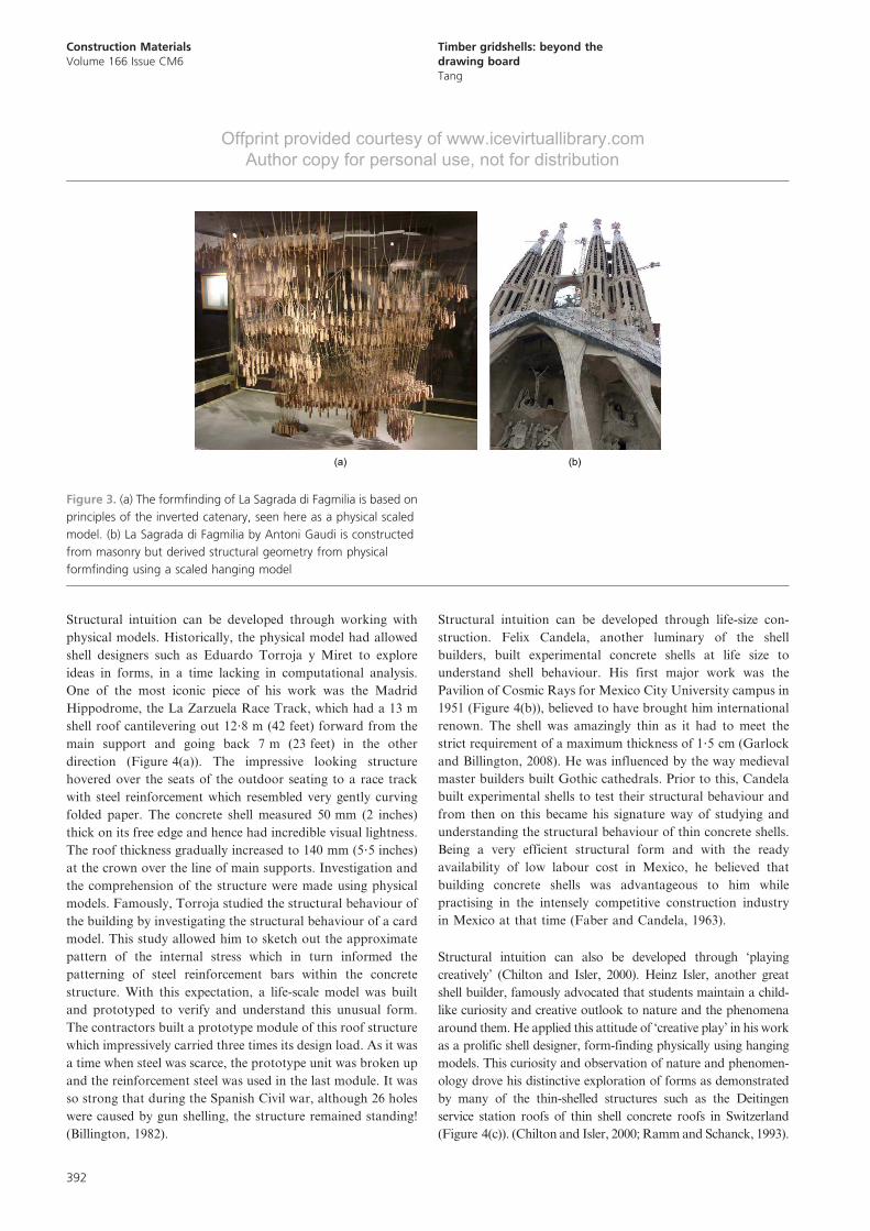
Formfinding of shells are closely related to inverted catenary
curves and were used byGaudi and Frei Otto in their work. Like
Antoni Gaudi who spectacularly used hanging chain models to
find the optimal shape for La Sagrada di Fagmilia (Figure 3(a)),
Frei Otto used hanging chain models to study the optimal shape
for gridshell structures to work structurally (Figure 3(b)).
The ways in which structure impacts on service co-ordination
and space layouts are important considerations. Aesthetically,
architects have responsibilities to inform and advise. To
understand structural rationale is therefore to understand a
correct way of building.
To take learning out of textbooks and formal lecture venues,
the construction workshop reinforces theory lessons and
Construction Materials
Volume 166 Issue CM6
Timber gridshells: beyond the drawing
board
Tang
Proceedings of the Institution of Civil Engineers
Construction Materials 166 December 2013 Issue CM6
Pages 390–402 http://dx.doi.org/10.1680/coma.12.00046
Paper 1200046
Received 10/10/2012 Accepted 26/08/2013
Keywords: design methods & aids/education & training/
shells
ice | proceedings ICE Publishing: All rights reserved
390

Offprint provided courtesy of www.icevirtuallibrary.com
Author copy for personal use, not for distribution
encourages on-site thinking, spontaneous problem-solving not
offered by conventional methods of teaching and learning in
the design studio environment.
One of the most successful structural artists, Pier Luigi Nervi
expressed strong views about educating architects with regards
to structure. In his 1965 writing for the Norton lectures at
Harvard University, he opposed the dictation of mathematical
calculations on structural forms – explaining creativity and
structural intuition as important proponents of design. He
emphasised the teaching of creativity and not only soulless
statics. The behaviour of material can be taught and explained,
but ultimately this can only be learned through seeing, feeling
and understanding how material reacts to different loading
conditions. Hence, only by experiencing this process of design
and construction first hand, can learning of material behaviour
effectively take place (Nervi, 1965).
Figure 1. The swells of the timber gridshell structure against the
backdrop of Sheffield
(a) (b)
(c) (d)
Figure 2. (a) Deployable timber lattice mats are used in the
construction of yurts by nomadic tribes in Mongolia. [By Aloxe
(Own work) (GFDL (http://www.gnu.org/copyleft/fdl.html)), via
Wikimedia Commons]. (b) The Multihalle at Mannheim, Germany
which was built in 1976 for the National German Garden Show still
stands to this day. (c) Weald and Downland Gridshell by Cullinan’s
Architects completed in 2002. (d) The roof of the 2005 Savill
Building in Windsor
Construction Materials
Volume 166 Issue CM6
Timber gridshells: beyond the
drawing board
Tang
391
Offprint provided courtesy of www.icevirtuallibrary.com
Author copy for personal use, not for distribution
Structural intuition can be developed through working with
physical models. Historically, the physical model had allowed
shell designers such as Eduardo Torroja y Miret to explore
ideas in forms, in a time lacking in computational analysis.
One of the most iconic piece of his work was the Madrid
Hippodrome, the La Zarzuela Race Track, which had a 13 m
shell roof cantilevering out 12?8 m (42 feet) forward from the
main support and going back 7 m (23 feet) in the other
direction (Figure 4(a)). The impressive looking structure
hovered over the seats of the outdoor seating to a race track
with steel reinforcement which resembled very gently curving
folded paper. The concrete shell measured 50 mm (2 inches)
thick on its free edge and hence had incredible visual lightness.
The roof thickness gradually increased to 140 mm (5?5 inches)
at the crown over the line of main supports. Investigation and
the comprehension of the structure were made using physical
models. Famously, Torroja studied the structural behaviour of
the building by investigating the structural behaviour of a card
model. This study allowed him to sketch out the approximate
pattern of the internal stress which in turn informed the
patterning of steel reinforcement bars within the concrete
structure. With this expectation, a life-scale model was built
and prototyped to verify and understand this unusual form.
The contractors built a prototype module of this roof structure
which impressively carried three times its design load. As it was
a time when steel was scarce, the prototype unit was broken up
and the reinforcement steel was used in the last module. It was
so strong that during the Spanish Civil war, although 26 holes
were caused by gun shelling, the structure remained standing!
(Billington, 1982).
Structural intuition can be developed through life-size con-
struction. Felix Candela, another luminary of the shell
builders, built experimental concrete shells at life size to
understand shell behaviour. His first major work was the
Pavilion of Cosmic Rays for Mexico City University campus in
1951 (Figure 4(b)), believed to have brought him international
renown. The shell was amazingly thin as it had to meet the
strict requirement of a maximum thickness of 1?5 cm (Garlock
and Billington, 2008). He was influenced by the way medieval
master builders built Gothic cathedrals. Prior to this, Candela
built experimental shells to test their structural behaviour and
from then on this became his signature way of studying and
understanding the structural behaviour of thin concrete shells.
Being a very efficient structural form and with the ready
availability of low labour cost in Mexico, he believed that
building concrete shells was advantageous to him while
practising in the intensely competitive construction industry
in Mexico at that time (Faber and Candela, 1963).
Structural intuition can also be developed through ‘playing
creatively’ (Chilton and Isler, 2000). Heinz Isler, another great
shell builder, famously advocated that students maintain a child-
like curiosity and creative outlook to nature and the phenomena
around them. He applied this attitude of ‘creative play’ in his work
as a prolific shell designer, form-finding physically using hanging
models. This curiosity and observation of nature and phenomen-
ology drove his distinctive exploration of forms as demonstrated
by many of the thin-shelled structures such as the Deitingen
service station roofs of thin shell concrete roofs in Switzerland
(Figure 4(c)). (Chilton and Isler, 2000; Rammand Schanck, 1993).
(a) (b)
Figure 3. (a) The formfinding of La Sagrada di Fagmilia is based on
principles of the inverted catenary, seen here as a physical scaled
model. (b) La Sagrada di Fagmilia by Antoni Gaudi is constructed
from masonry but derived structural geometry from physical
formfinding using a scaled hanging model
Construction Materials
Volume 166 Issue CM6
Timber gridshells: beyond the
drawing board
Tang
392

Offprint provided courtesy of www.icevirtuallibrary.com
Author copy for personal use, not for distribution
2. The workshop: preparations, materialsand programme
Construction workshops serve as an effective way of educating
the architects of the future. Workshops that help students to
learn have been developed in technology teaching at uni-
versities globally. At UNAM in Mexico City, construction
workshop sessions are used to aid structural understanding
(Oliva-Salinas, 2007). Structural learning are also guided by
technology teaching via life-size construction workshops in
Denmark (Figure 5) (Larsen et al., 2010)
Understanding material, their tectonic, structural qualities and
behaviour are crucial in an architect’s education. The ability to
consider the construction process in design is an important part
of learning about the art of building.
A workshop to design gridshells by using a physical form-
finding method therefore offers an opportunity to enhance the
education of a young architect/technologist. The experience of
life-size construction, with an end result that is both physical
and spatial, is believed to reinforce communication skills,
construction thinking and material sensibilities. The handling
of material, the physicality of the activity and the tangible
structure also simulate a realness and excitement in construc-
tion – not just an exercise restricted to pen and paper, drawing
board or computer space. Importantly, construction work-
shops add value in terms of cognitive learning that broadens
their architectural thinking, encompassing considerations of
buildability and construction processes – a view shared by
Carpenter in 1997 who wrote that
structure, detailing, design issues, and construction strategy are all
debated in the hands-on atmosphere of three-dimensional reality.
The best architects understand the logic and poetics of construction
and the best way to teach this is to build (Carpenter, 1997, p. 46,
quoted in Jann (2009), quoted in Shannon and Radford (2011)).
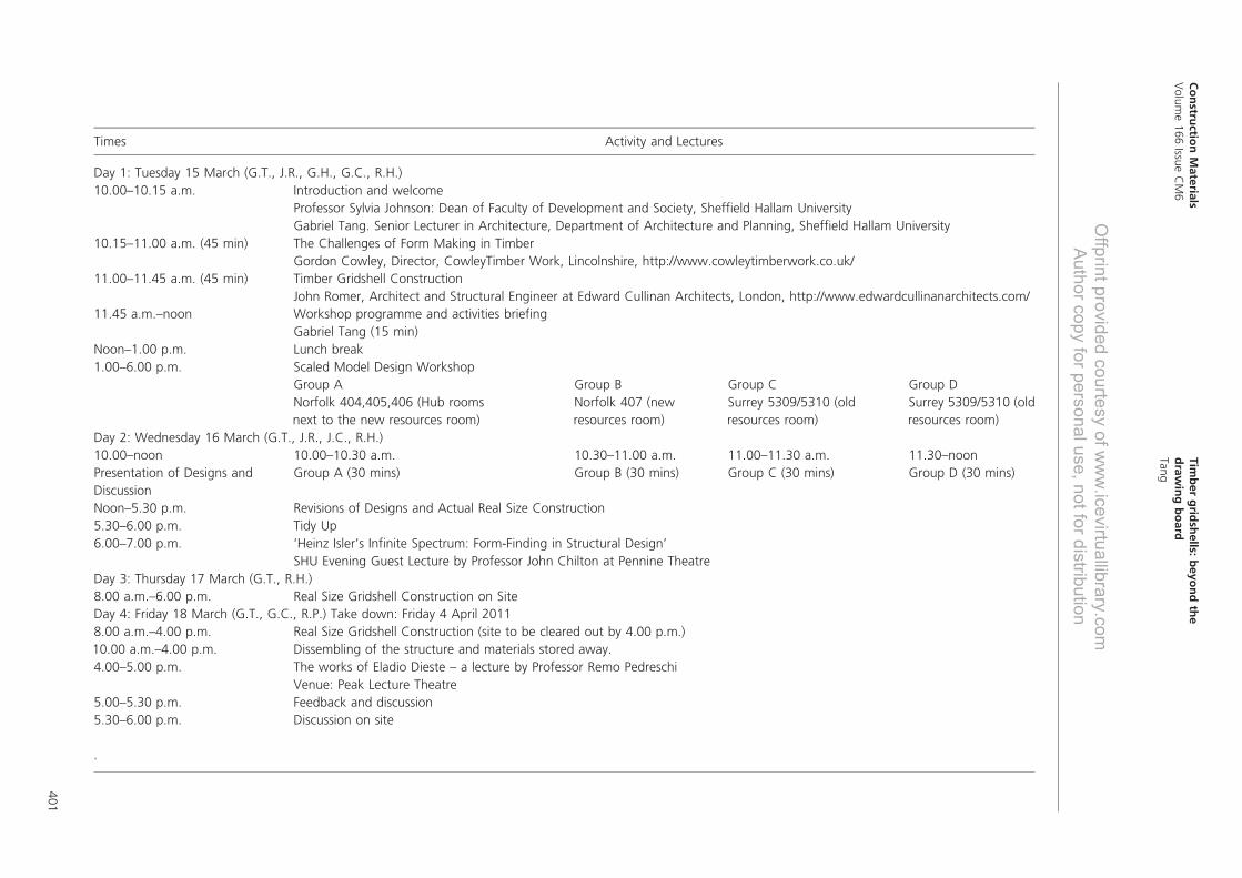
A timetable that describes the activities of a week-long work-
shop held at Sheffield Hallam University, UK, in March 2011 is
presented in the Appendix.
The workshop commenced with introductory lectures from
invited guest speakers relating to the theories of gridshell and
practical experiences from lightweight structure design and
construction. It must be stressed that the presentation of basic
principles of gridshell design is important to meet the learning
(a) (b)
(c) (d)
Figure 4. (a) Thin repeated concrete shells form the canopy of La
Zarzuela Hippodromo roof by Torroja [By Outisnn (Own work)
(GFDL (http://www.gnu.org/copyleft/fdl.html)), via Wikimedia
Commons]. (b) Cosmic Ray Pavilion, Mexico City by Felix Candela
(1951) [By GAED (Own work) [Public domain], via Wikimedia
Commons Figure 5(c)]. (c) Deitingen service station roofs in thin
shell concrete designed by Heinz Isler [By (Own work) (CC-
BY-SA-3.0 (http://creativecommons.org/licenses/by-sa/3.0)), via
Wikimedia Commons]. (d) Palazzetto dello Sport, Rome, Italy by PL
Nervi (1956–1957)
Construction Materials
Volume 166 Issue CM6
Timber gridshells: beyond the
drawing board
Tang
393

Offprint provided courtesy of www.icevirtuallibrary.com
Author copy for personal use, not for distribution
outcomes. Various practical problems faced by previous
designers were presented to achieve a broad understanding of
problems and solutions encountered by their designers and
builders. The lecture programme therefore provided instruc-
tions and a strong theoretical background and foundation
upon which the ensuing practical construction could build.
Following these lectures, the students researched and designed
the structure in teams by making physical card models. They
then presented their designs to decide which design to build
(Figure 6(a) and (b)).
Throughout the week, breaks from the construction activity took
place in the form of supplementary lectures by various speakers.
The structure was designed and built by the students at the
upper lawns in Sheffield city centre belonging to the University
with advice, guidance and expertise from guest speakers who
visited at different times during the week.
To anchor the timber gridshell onto the ground, a system of
restraining pegs and wooden blocks were used. As such, 40 iron
pegs made by the technical team by bending iron rods, diameter
8 mm, to J-shapes were prepared. In addition, 20 timber blocks
measuring 190 mm 6 70 mm 6 45 mm with a notch 70 mm
long and 10 mm deep was cut out from each block. Two holes of
diameter 5 mm were drilled through at both ends as illustrated
in Figure 6(c). These cost £100 to make.
Nine hundred and twenty pieces of softwood pine laths with
section 12 mm by 3 5 mm and 2?1 m long were purchased from
a local timber yard, costing £1000. They were pre-drilled with
holes of diameter 5 mm in the technical studio to a pattern
worked out by building a mock-up to test out the grid pattern.
Nuts and bolts costing a total of £130 were purchased. Rope
and miscellaneous materials cost £100. The materials were
assembled using spanners and drills which the University
already owned.
The construction used conventional materials in an unconven-
tional construction solution and employed inexpensive mate-
rial and tools that are readily available.
In total, the workshop cost £1330 for materials and pre-
paratory labour.
2.1 The workshop: design, testing, construction
To formfind and understand the behaviour of such structures,
pastecard which was 1?5 mm thick was first cut into strips that
were 5 mm wide. They were arranged in a lattice to form free
scissor joints and pin-jointed to create a mat that could be
deformed. The simple square grid was capable of deforming
into diamonds, effecting a change of overall length of the mat
(Figure 7(a)).
It was observed that the direction in which the grid was laid
affected the behaviour of the mat. Initially, the mat in
Figure 7(b) was made by laying a grid parallel to the edges
of the mat. When pulled or pushed together, the rectangular
mat transformed into a rhombus with two sharp-pointed
opposite corners at a flat dimension.
(a) (b)
Figure 5. (a) During a construction workshop in Denmark in 2010,
students first designed the gridshell using a scaled model. (b) Using
bamboo spliced together using plastic cable ties, the actual model
was subsequently built using the physical model as a guide
Construction Materials
Volume 166 Issue CM6
Timber gridshells: beyond the
drawing board
Tang
394

Offprint provided courtesy of www.icevirtuallibrary.com
Author copy for personal use, not for distribution
To investigate the nature of deformation, an alternative
mat with a diagonal grid orientation was made to investi-
gate this mat behaviour. When compressed, the mat main-
tained the rectangular geometry. On the flat dimension,
compared to the previous option, no sharp corners were
formed (Figure 7(c)).
By deforming the grid, the overall dimension lengthened or
shortened. Following that, by restraining specific points to the
ground, pushing the mat from a flat plane can produce the
three-dimensional shell illustrated in Figure 7(d). The material
responds to the application of forces to create undulations and
readjustments in the grid patterns to bring about three-
dimensional deformation – with an understanding of material
behaviour coming from the need to create architectural space.
This understanding and appreciation of mat behaviour was
used to design the grid shell. By selecting specific points as
stationary reference points, the mat can be pulled (by applying
tension forces) or pushed (by applying compression forces).
Subjected to these forces, it was possible to create spectacular
three-dimensional grid forms exhibiting shell morphology from
a flat mat (Figure 7(e)).
The design is then pinned down onto a polystyrene board.
Eventually, a mat at 1 : 50 scale was made as this was judged an
appropriate scale to allow transformation deformation to be
workable and visible (Figure 7(f)). For expediency, it was
assumed that the behaviour in the card strip model would equate
and translate in principle into timber laths at the actual scale.
The grid size of 900 mm square was determined by the length
of the actual timber laths and also the overlap splicing
dimensions to allow the mat to become buildable with the
2?1 m timber laths.
Without mathematical calculation and verification, students
could understand how grid orientation affected the behaviour
(a)
(b) (c)
Figure 6. (a) Physical model-making by workshop participants
encouraged structural, architecture and constructional
consideration. (b) The flat gridmat lattice was made by pinning
paper strips at their intersection points. (c) The anchoring system
consists of a timber block and iron pegs that are hammered into
the earth to anchor the gridshell
Construction Materials
Volume 166 Issue CM6
Timber gridshells: beyond the
drawing board
Tang
395

Offprint provided courtesy of www.icevirtuallibrary.com
Author copy for personal use, not for distribution
of mat deformation. The students learned how three-dimen-
sional deformation could take place by deforming the flat mat
first, then pulling (tensioning) or pushing it (compression) to
achieve deformation in three dimensions (Figure 8(a)). The
participants were able to see, feel and understand the forces
acting within the deformed mat to exhibit shell action. Playing
creatively and objectively with the lattice card mat was
imperative to understanding material behaviour of the mat –
one which differs from that of their constituent timber laths.
Material failure tests (Figure 8(b)) were carried out to check
for the suitability of pine laths. They went through a simple jig
test to check that the timber could be bent to an arc of 2 m
radius without snapping. A natural material, timber laths
contain knots where the laths broke during testing. Following
the tests, 40% of the timber material failed (snapped) and were
rejected.
2.2 The design: the swells
By manipulating, studying, making and subsequently under-
standing the gridmat, it was noticed that for the mat to become
usable when stretched, the grid pattern had to be diagonal as
this deformation did not produce sharp pointed corners which
rendered the mat less useful.
(a) (b)
(c)
Pinned down
Pinned down
(e) (f)
(d)
Figure 7. (a) Original flat latticed mat. (b) Original flat latticed mat
has transformed into a rhombus when forces according to arrows
are pulled. (c) An alternative lattice mat with a diagonal grid pattern.
(d) The mat closes up when in-plane forces are applied, retaining
mat dimension. (e) Simple three-dimensional deformation can be
achieved by fixing specific points and applying compressive forces to
a two-dimensional pre-deformed flat mat. (f) Experimentation of
form design with physical deployable gridmat models applying
principles of deformation helps to achieve sophisticated geometries,
most displaying shell action
Construction Materials
Volume 166 Issue CM6
Timber gridshells: beyond the
drawing board
Tang
396
Offprint provided courtesy of www.icevirtuallibrary.com
Author copy for personal use, not for distribution
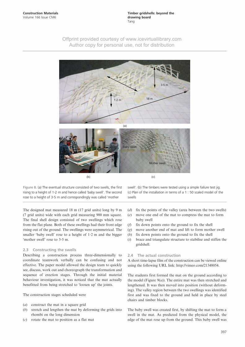
The designed mat measured 18 m (17 grid units) long by 9 m
(7 grid units) wide with each grid measuring 900 mm square.
The final shell design consisted of two swellings which rose
from the flat plane. Both of these swellings had their front edge
rising out of the ground. The swellings were asymmetrical. The
smaller ‘baby swell’ rose to a height of 1?2 m and the bigger
‘mother swell’ rose to 3?5 m.
2.3 Constructing the swells
Describing a construction process three-dimensionally to
coordinate teamwork verbally can be confusing and not
effective. The paper model allowed the design team to quickly
see, discuss, work out and choreograph the transformation and
sequence of erection stages. Through the initial material
behaviour investigation, it was noticed that the mat actually
benefitted from being stretched to ‘loosen up’ the joints.
The construction stages scheduled were
(a) construct the mat in a square grid
(b) stretch and lengthen the mat by deforming the grids into
rhombi on the long dimension
(c) rotate the mat to position as a flat mat
(d) fix the points of the valley (area between the two swells)
(e) move one end of the mat to compress the mat to form
baby swell
(f) fix down points onto the ground to fix the shell
(g) move another end of mat and lift to form mother swell
(h) fix down points onto the ground to fix the shell
(i) brace and triangulate structure to stabilise and stiffen the
gridshell.
2.4 The actual construction
A short time-lapse film of the construction can be viewed online
using the following URL link: http://vimeo.com/21348054.
The students first formed the mat on the ground according to
the model (Figure 9(a)). The entire mat was then stretched and
lengthened. It was then moved into position (without deform-
ing). The valley region between the two swellings was identified
first and was fixed to the ground and held in place by steel
chairs and timber blocks.
The baby swell was created first, by shifting the mat to form a
swell in the mat. As predicted from the physical model, the
edge of the mat rose up from the ground. This baby swell was
(b) (c)
(a)
9 m
Baby swell
Mother swell
3.5 m
18 m1.2 m
Figure 8. (a) The eventual structure consisted of two swells, the first
rising to a height of 1?2 m and hence called ‘baby swell’. The second
rose to a height of 3?5 m and correspondingly was called ‘mother
swell’. (b) The timbers were tested using a simple failure test jig.
(c) Plan of the installation in terms of a 1 : 50 scaled model of the
swells
Construction Materials
Volume 166 Issue CM6
Timber gridshells: beyond the
drawing board
Tang
397

Offprint provided courtesy of www.icevirtuallibrary.com
Author copy for personal use, not for distribution
fixed onto the ground. It was subsequently fixed into position
by fixing bracing pieces to triangulate the structure and thereby
freezing the geometry.
The mother swell was formed in a similar way (Figure 9(b) and
9(c)) – students held specific points and by moving towards or
away, the bigger swell was created. This time, it rose to 3?5 m
and was fixed similarly using metal chairs and timber
blocks. Bracing pieces were bolted together from the timber
laths and fixed to triangulate and stabilise the entire structure
(Figure 9(d)).
3. Evaluation
The process of construction addressed many important
considerations of structural design and construction thinking.
In this exercise, it was easy to create single long flexible
members from card at 1 : 50 scale. When scaled up, the
students had to think about how a single continuous element
can be achieved from 1?2 m long timber laths.
Transportation logistics was an important point to consider.
The shorter 2?1 m timber sections allowed the timber to be
transported in lifts and carried around staircases to the lawned
areas. Longer laths would create difficulties in transporting the
fragile material. In fact, this same issue of portability arose in
previous constructions of timber gridshells. In the Weald and
Downland Gridshell by Edward Cullinan’s Architects, shorter
timber sections had to be scarf-jointed under a poly tunnel
cover to be kept dry. Using the drop-down system, the timber
members had to be first transported up to a high roof level to
create a gridmat before being dropped into position. This was
managed ingeniously by sliding them through a hollow poly
pipe (recorded interview with Corbett, 2009).
In such projects, communication is the key, requiring
effectively a creative, collaborative and reiterative respect and
relationship between the architect, the contractor/builder and
the engineer. In this hands-on workshop, the students took on
a tri-partite role, appreciating and empathising with the
importance of each party in the realisation of such a project.
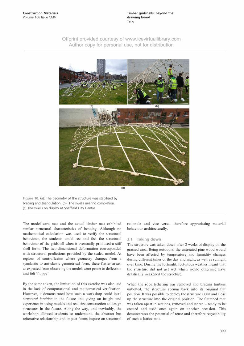
In this workshop, mathematical analysis was deliberately de-
prioritised to induce the freedom for intuitive design for
structural correctness in geometry and morphology. Structural
correctness was crucial in the design of form-active shell
structures where stiffness and stability depended on having
correct geometry and morphology. Shell stiffness and stability
were controlled by increasing or reducing the curvature of the
structure – a structural behaviour that the students learned
through designing and building (Figure 10).
(a) (b)
(c) (d)
Figure 9. (a) The gridmat was constructed flat on the ground by
splicing timber laths. (b) The gridmat was stretched and shifted into
position. (c) The gridmat was compressed to form the baby swell.
(d): The mother swell is formed
Construction Materials
Volume 166 Issue CM6
Timber gridshells: beyond the
drawing board
Tang
398
Offprint provided courtesy of www.icevirtuallibrary.com
Author copy for personal use, not for distribution
The model card mat and the actual timber mat exhibited
similar structural characteristics of bending. Although no
mathematical calculation was used to verify the structural
behaviour, the students could see and feel the structural
behaviour of the gridshell when it eventually produced a stiff
shell form. The two-dimensional deformation corresponded
with structural predictions provided by the scaled model. At
regions of contraflexion where geometry changes from a
synclastic to anticlastic geometrical form, these flatter areas,
as expected from observing the model, were prone to deflection
and felt ‘floppy’.
By the same token, the limitation of this exercise was also laid
in the lack of computational and mathematical verification.
However, it demonstrated how such a workshop could instil
structural intuition in the future and giving an insight and
experience in using models and real-size construction to design
structures in the future. Along the way, and inevitably, the
workshop allowed students to understand the abstract but
reiterative relationship and impact forms impose on structural
rationale and vice versa, therefore appreciating material
behaviour architecturally.
3.1 Taking down
The structure was taken down after 2 weeks of display on the
grassed area. Being outdoors, the untreated pine wood would
have been affected by temperature and humidity changes
during different times of the day and night, as well as sunlight
over time. During the fortnight, fortuitous weather meant that
the structure did not get wet which would otherwise have
drastically weakened the structure.
When the rope tethering was removed and bracing timbers
unbolted, the structure sprung back into its original flat
position. It was possible to deploy the structure again and close
up the structure into the original position. The flattened mat
was taken apart in sections, removed and stored – ready to be
erected and used once again on another occasion. This
demonstrates the potential of reuse and therefore recyclability
of such a lattice mat.
(a)
(c)
(b)
Figure 10. (a): The geometry of the structure was stabilised by
bracing and triangulation. (b): The swells nearing completion.
(c) The swells on display at Sheffield City Centre
Construction Materials
Volume 166 Issue CM6
Timber gridshells: beyond the
drawing board
Tang
399
Offprint provided courtesy of www.icevirtuallibrary.com
Author copy for personal use, not for distribution
4. ConclusionThe workshop proved invaluable as a learning resource of not
only understanding construction materials, but also under-
standing various aspects of construction and architectural
pedagogy which is fundamentally experiential-based. The
workshop was an exercise of experiential learning (Kolb, 1984)
where abstract concepts and generalisation were introduced
during the first lectures. The testing of the concepts in a new
situation takes place when the students design by models and
envisage all the problems experienced designers encounter. The
concrete experience of actual construction allowed the students
to learn from their construction exercises, solving spontaneously
as the construction took place. Eventually, the observations and
reflection stage begins as they quickly learned and were able to
apply their new experience in a future situation, perhaps in the
designing of a timber gridshell in the future.
The construction and material behaviour portrayed an unusual
perspective to material use – bending – considered by many as
an inherent weakness of timber. In this instance, the short-
coming becomes a desirable property for a timber gridshell.
This was an unconventional way of using timber. Like
plywood and glue lamination manufacturing in which layers
of wood are glued to form an engineered construction material
with more structural control, this construction process made
use of bending and flexibility of timber.
In fact, this was first described as the originator of the construction
of the forest buildings of Hooke Park – the free availability of
saplings in the forest which grew weak among the stronger and
straighter-growing trees in managed forests (Herzog et al., 2004).
The construction of timber gridshells was borne from a sustainable
technology of construction – by using a carbon neutral resource,
which otherwise will become a waste product of forestry.
The workshop was an enlightening way of allowing students to
experiment and construct a structure and experience the
interaction between material, the designer and builder. This
offered an invaluable platform for the architecture student to
communicate by drawing, model-making and allow them to
develop ad-hoc solving problem skills and learn about
materials. This exercise emphasised the importance of the
physical model-making to bring designs out of the drawing
board. Such construction workshops continue to have an
impact on curriculum teaching and learning in the education of
an architectural professional of the future.
Acknowledgements
The author would like to express thanks to all the enthusia-
stic students of architecture and architectural technology at
Sheffield Hallam University who participated and collaborated
in the 2011 workshop. Many thanks also go out to all practis-
ing architects and technologists (John Romer of Edward
Cullinan Architects, London and Gordon Cowley of Cowley
Timberwork. Lincolnshire), engineers (Greg Hardie and
Richard Harpin, ARUPs) and academics (Professor John
Chilton, Professor Remo Pedreschi) during this week-long
workshop. Many thanks are also extended to the staff within
the technical workshops and the Learning, Teaching and
Assessment Department of Sheffield Hallam University who
generously sponsored this workshop. Many thanks also go to
Professor Julian Marsh for his help and support with the
workshop and to journal paper reviewers for their constructive
comments.
Appendix
Timber Gridshell week-long workshop, 15–18 March 2011:
activity programme
Construction Materials
Volume 166 Issue CM6
Timber gridshells: beyond the
drawing board
Tang
400
Offp
rint p
rovid
ed c
ourte
sy o
f ww
w.ic
evirtu
allib
rary
.com
Auth
or c
opy fo
r pers
onal u
se, n
ot fo
r dis
tributio
n
Times Activity and Lectures
Day 1: Tuesday 15 March (G.T., J.R., G.H., G.C., R.H.)
10.00–10.15 a.m. Introduction and welcome
Professor Sylvia Johnson: Dean of Faculty of Development and Society, Sheffield Hallam University
Gabriel Tang. Senior Lecturer in Architecture, Department of Architecture and Planning, Sheffield Hallam University
10.15–11.00 a.m. (45 min) The Challenges of Form Making in Timber
Gordon Cowley, Director, CowleyTimber Work, Lincolnshire, http://www.cowleytimberwork.co.uk/
11.00–11.45 a.m. (45 min) Timber Gridshell Construction
John Romer, Architect and Structural Engineer at Edward Cullinan Architects, London, http://www.edwardcullinanarchitects.com/
11.45 a.m.–noon Workshop programme and activities briefing
Gabriel Tang (15 min)
Noon–1.00 p.m. Lunch break
1.00–6.00 p.m. Scaled Model Design Workshop
Group A
Norfolk 404,405,406 (Hub rooms
next to the new resources room)
Group B
Norfolk 407 (new
resources room)
Group C
Surrey 5309/5310 (old
resources room)
Group D
Surrey 5309/5310 (old
resources room)
Day 2: Wednesday 16 March (G.T., J.R., J.C., R.H.)
10.00–noon 10.00–10.30 a.m. 10.30–11.00 a.m. 11.00–11.30 a.m. 11.30–noon
Presentation of Designs and
Discussion
Group A (30 mins) Group B (30 mins) Group C (30 mins) Group D (30 mins)
Noon–5.30 p.m. Revisions of Designs and Actual Real Size Construction
5.30–6.00 p.m. Tidy Up
6.00–7.00 p.m. ‘Heinz Isler’s Infinite Spectrum: Form-Finding in Structural Design’
SHU Evening Guest Lecture by Professor John Chilton at Pennine Theatre
Day 3: Thursday 17 March (G.T., R.H.)
8.00 a.m.–6.00 p.m. Real Size Gridshell Construction on Site
Day 4: Friday 18 March (G.T., G.C., R.P.) Take down: Friday 4 April 2011
8.00 a.m.–4.00 p.m. Real Size Gridshell Construction (site to be cleared out by 4.00 p.m.)
10.00 a.m.–4.00 p.m. Dissembling of the structure and materials stored away.
4.00–5.00 p.m. The works of Eladio Dieste – a lecture by Professor Remo Pedreschi
Venue: Peak Lecture Theatre
5.00–5.30 p.m. Feedback and discussion
5.30–6.00 p.m. Discussion on site
.
Constru
ctionMateria
ls
Volume166Issu
eCM6
Tim
bergrid
shells:
beyondthe
drawingboard
Tang
401
Offprint provided courtesy of www.icevirtuallibrary.com
Author copy for personal use, not for distribution
REFERENCES
Billington DP (1982) Thin Shell Concrete Structures, 2nd edn.
McGraw-Hill Book Co., New York, NY, USA.
Carpenter W (ed.) (1997) Learning by Building: Design and
Construction in Architectural Education. Van Nostrand
Reinhold, New York, NY, USA.
Chilton J and Isler H (2000) The Engineer’s Contribution to
Contemporary Architecture. Thomas Telford, London, UK,
pp. 5–159.
Corbett S (2009) Chief Carpenter at Weald and Downland
Jerwood Gridshell. Recorded interview, 10 June 2009.
Faber C and Candela F (1963) Candela: The Shell Builder.
Reinhold Publishing Corporation, New York, NY, USA.
Garlock M and Billington DP (2008) Felix Candela: Engineer,
Builder, Structural Artist. Yale University Press, New
Haven, CT, USA.
Happold E and Liddell WI (1975) Timber lattice roof for the
Mannheim Bundesgartenshau. The Structural Engineer
53(3): 99–135.
Harris R, Kelly O and Dickson M (2003) Downland Gridshell – an
innovation in timber design. Proceedings of the Institution
of Civil Engineers – Civil Engineering 156(1): 26–33.
Herzog T, Natterer J, Schweitzer R, Volz M and Winter W (2004)
Timber Construction Manual. Birkhauser Edition Detail,
Munich, Germany.
JannM (2009)Revamping Architectural Education: Ethics, Social
Service, and Innovation. See http://www.march-todach.com/
index_files/Revamping.pdf (accessed 01/05/2013).
Kohb D (1984) Experiential Learning: Experience as the Source
of Learning and Development. Prentice-Hall, Englewood
Cliffs, NJ, USA.
Popovic-Larsen O, Tang G and Lee D (2010) Innovative spatial
timber structures: workshops with physical modeling
explorations from small to full scale. In Proceedings of the
International Symposium of the International Association for
Shell and Spatial Structures (IASS), Shanghai, China, 8–12
November, 2010 (Zhang Q (ed.)). Architecture & Building
Press, Beijing, China, pp. 106–107.
Nervi PL (1965) Aesthetics and Technology in Building. Harvard
University Press, Cambridge, MA, USA.
Oliva-Salinas JG (2007) The teaching of structures in
architecture. In Proceedings of International Symposium of
the International Association for Shell and Spatial
Structures (IASS): Structural Architecture – Towards the
Future Looking to the Past, Venice, Italy, 3–6 December
2007 (Majowiecki M (ed.)), University Iuav of Venice:
Department of Architectural Construction, Venedig,
Italy.
Ramm E and Schanck E (eds) (1993) Heinz Isler – Schalen.
Katalog zur Ausstellung. 3 Erganzte Ausgabe. VDF
Hochschule Verlag an der ETH, Zurich, Switzerland (in
German).
Shannon S and Radford A (2011) Iteration as a strategy for
teaching architectural technologies in an architecture studio,
Architectural Science Review 53(2): 238–250. See http://www.
tandfonline.com/loi/tasr20 (accessed 01/05/2013).
WHAT DO YOU THINK?
To discuss this paper, please email up to 500 words to the
editor at [email protected]. Your contribution will be
forwarded to the author(s) for a reply and, if considered
appropriate by the editorial panel, will be published as
discussion in a future issue of the journal.
Proceedings journals rely entirely on contributions sent in
by civil engineering professionals, academics and stu-
dents. Papers should be 2000–5000 words long (briefing
papers should be 1000–2000 words long), with adequate
illustrations and references. You can submit your paper
online via www.icevirtuallibrary.com/content/journals,
where you will also find detailed author guidelines.
Construction Materials
Volume 166 Issue CM6
Timber gridshells: beyond the
drawing board
Tang
402