linux enriched design in second generation warp - oulu
TRANSCRIPT

DEGREE PROGRAM IN ELECTRICAL ENGINEERING
LINUX ENRICHED DESIGN IN
SECOND GENERATION WARP
Author ____________________________________
Jaakko Niemelä
Supervisor ____________________________________
Juha Röning
Accepted ______ / ______ 2012
Grade ____________________________________
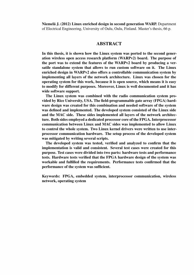
Niemelä J. (2012) Linux enriched design in second generation WARP. Departmentof Electrical Engineering, University of Oulu, Oulu, Finland. Master’s thesis, 66 p.
ABSTRACT
In this thesis, it is shown how the Linux system was ported to the second gener-ation wireless open access research platform (WARPv2) board. The purpose ofthe port was to extend the features of the WARPv2 board by producing a ver-satile standalone system that allows to run custom software on it. The Linuxenriched design in WARPv2 also offers a controllable communication system byimplementing all layers of the network architecture. Linux was chosen for theoperating system for this work, because it is open source, which means it is easyto modify for different purposes. Moreover, Linux is well documented and it haswide software support.
The Linux system was combined with the radio communication system pro-vided by Rice University, USA. The field-programmable gate array (FPGA) hard-ware design was created for this combination and needed software of the systemwas defined and implemented. The developed system consisted of the Linux sideand the MAC side. These sides implemented all layers of the network architec-ture. Both sides employed a dedicated processor core of the FPGA. Interprocessorcommunication between Linux and MAC sides was implemented to allow Linuxto control the whole system. Two Linux kernel drivers were written to use inter-processor communication hardware. The setup process of the developed systemwas mitigated by writing several scripts.
The developed system was tested, verified and analyzed to confirm that theimplementation is valid and consistent. Several test cases were created for thispurpose. Test cases were divided into two parts: hardware tests and performancetests. Hardware tests verified that the FPGA hardware design of the system wasworkable and fulfilled the requirements. Performance tests confirmed that theperformance of the system was sufficient.
Keywords: FPGA, embedded system, interprocessor communication, wirelessnetwork, operating system

Niemelä J. (2012) Linuxin sovitus toisen sukupolven WARP-kehitysalustalle. Oulunyliopisto, sähkötekniikan osasto. Diplomityö, 66 s.
TIIVISTELMÄ
Tässä työssä sovitettiin Linux-järjestelmä langattomalle kehitysalustalle (WARPv2).Sovitus tehtiin, jotta kehitysalustasta saataisiin monipuolinen ja itsenäinen. Lisäk-si sovitus mahdollisti omien ohjelmien ajon alustalla sekä verkkoarkkitehtuurinkaikkien kerrosten hallittavuuden. Linux valittiin tämän työn käyttöjärjestelmäk-si, sillä sen lähdekoodi on avoimesti saatavilla ja täten helposti muokattavissa eritarkoituksiin sopivaksi. Linux on myös hyvin dokumentoitu ja sille on saatavillarunsaasti sovelluksia.
Linux-järjestelmä yhdistettiin yhdysvaltalaisen Ricen yliopiston kehittämäänlangattomaan tiedonsiirtototeutukseen. Kehitysalustan FPGA-piirille suunnitel-tiin tälle yhdistelmälle sopiva laitteistototeutus ja tarvittavat ohjelmistot määri-teltiin ja liitettiin mukaan järjestelmään. Kehitetty järjestelmä koostui Linux-osasta ja MAC-osasta. Nämä osat toteuttivat verkkoarkkitehtuurin kaikki ker-rokset. Molemmille osille oli osoitettu oma suoritin FPGA-piiriltä. Linux- jaMAC-osan välille toteutettiin tiedonvälitysmekanismi, jotta Linux kykenisi hal-litsemaan koko järjestelmää. Lisäksi Linuxille kirjoitettiin kaksi laitteistoajuriaLinux- ja MAC-osien välisen tiedonvälityksen mahdollistamiseksi. Järjestelmänkäyttöönoton helpottamiseksi kirjoitettiin useita komentosarjoja.
Kehitetty järjestelmä testattiin, todennettiin ja analysoitiin järjestelmän toimi-vuuden varmistamiseksi. Testausta varten kehitettiin useita testitapauksia. Tes-taus koostui kahdesta osasta: laitteistotestauksesta ja suorituskykytestauksesta.Laitteistotestauksessa todennettiin laitteiston vaatimusten mukainen toiminta,kun taas suorituskykytestaussa varmistettiin suorituskykyvaatimusten täyttymi-nen.
Avainsanat: fpga, sulautettu järjestelmä, prosessorien välinen tiedonvälitys, lan-gaton verkko, käyttöjärjestelmä

CONTENTS
ABSTRACT
TIIVISTELMÄ
PREFACE
LIST OF SYMBOLS AND ABBREVIATIONS
1. INTRODUCTION 9
2. LINUX IN EMBEDDED SYSTEMS 112.1. Tasks of the Linux kernel . . . . . . . . . . . . . . . . . . . . . . . . 122.2. Kernel modules . . . . . . . . . . . . . . . . . . . . . . . . . . . . . 132.3. Device drivers . . . . . . . . . . . . . . . . . . . . . . . . . . . . . . 142.4. Configuring and building the kernel . . . . . . . . . . . . . . . . . . 15
2.4.1. Configuring the kernel . . . . . . . . . . . . . . . . . . . . . 152.4.2. Building the kernel . . . . . . . . . . . . . . . . . . . . . . . 162.4.3. Booting the compiled kernel . . . . . . . . . . . . . . . . . . 17
2.5. Debugging . . . . . . . . . . . . . . . . . . . . . . . . . . . . . . . . 182.5.1. Pre-boot debugging . . . . . . . . . . . . . . . . . . . . . . . 202.5.2. Run-time debugging . . . . . . . . . . . . . . . . . . . . . . 21
2.6. Embedded Linux distributions . . . . . . . . . . . . . . . . . . . . . 212.6.1. Commercial embedded Linux distributions . . . . . . . . . . 222.6.2. Meta-distributions . . . . . . . . . . . . . . . . . . . . . . . 222.6.3. Miniature desktop distributions . . . . . . . . . . . . . . . . 232.6.4. Complete software stacks . . . . . . . . . . . . . . . . . . . 232.6.5. Comparison of embedded Linux distributions . . . . . . . . . 23
2.7. Busybox . . . . . . . . . . . . . . . . . . . . . . . . . . . . . . . . . 242.8. Porting Linux . . . . . . . . . . . . . . . . . . . . . . . . . . . . . . 24
2.8.1. Organization of the Linux source tree . . . . . . . . . . . . . 242.8.2. Porting Linux to a Xilinx FPGA board . . . . . . . . . . . . . 25
3. WARP DEVELOPMENT PLATFORM 273.1. Architecture . . . . . . . . . . . . . . . . . . . . . . . . . . . . . . . 273.2. Hardware . . . . . . . . . . . . . . . . . . . . . . . . . . . . . . . . 28
3.2.1. FPGA . . . . . . . . . . . . . . . . . . . . . . . . . . . . . . 283.2.2. Power . . . . . . . . . . . . . . . . . . . . . . . . . . . . . . 283.2.3. Memory . . . . . . . . . . . . . . . . . . . . . . . . . . . . . 293.2.4. I/O –devices . . . . . . . . . . . . . . . . . . . . . . . . . . 293.2.5. Clocking . . . . . . . . . . . . . . . . . . . . . . . . . . . . 303.2.6. Ethernet . . . . . . . . . . . . . . . . . . . . . . . . . . . . . 313.2.7. Daughtercards . . . . . . . . . . . . . . . . . . . . . . . . . 32
3.3. The WARP OFDM reference design . . . . . . . . . . . . . . . . . . 323.4. Design process flow and design tools for FPGA developing . . . . . . 35
3.4.1. Xilinx Platform studio . . . . . . . . . . . . . . . . . . . . . 35

4. PORTING LINUX TO THE WARP BOARD 384.1. Design flow . . . . . . . . . . . . . . . . . . . . . . . . . . . . . . . 394.2. Hardware design . . . . . . . . . . . . . . . . . . . . . . . . . . . . 40
4.2.1. Interprocessor communication . . . . . . . . . . . . . . . . . 414.2.2. Clocking . . . . . . . . . . . . . . . . . . . . . . . . . . . . 42
4.3. Software design . . . . . . . . . . . . . . . . . . . . . . . . . . . . . 434.3.1. Kernel configuration . . . . . . . . . . . . . . . . . . . . . . 434.3.2. Communication between PowerPC cores . . . . . . . . . . . 434.3.3. Root filesystem . . . . . . . . . . . . . . . . . . . . . . . . . 444.3.4. Applications . . . . . . . . . . . . . . . . . . . . . . . . . . 45
4.4. Building the system . . . . . . . . . . . . . . . . . . . . . . . . . . . 464.4.1. Setup scripts . . . . . . . . . . . . . . . . . . . . . . . . . . 47
4.5. Booting the system . . . . . . . . . . . . . . . . . . . . . . . . . . . 484.6. Debugging . . . . . . . . . . . . . . . . . . . . . . . . . . . . . . . . 48
5. TESTING, VERIFICATION AND ANALYSIS 505.1. Test cases . . . . . . . . . . . . . . . . . . . . . . . . . . . . . . . . 50
5.1.1. Hardware tests . . . . . . . . . . . . . . . . . . . . . . . . . 505.1.2. Performance tests . . . . . . . . . . . . . . . . . . . . . . . . 51
5.2. Test results . . . . . . . . . . . . . . . . . . . . . . . . . . . . . . . 525.3. FPGA resource usage analysis . . . . . . . . . . . . . . . . . . . . . 55
6. DISCUSSION 56
7. SUMMARY 58
8. REFERENCES 59
9. APPENDICES 64

PREFACE
This Master’s thesis has been made as part of the Cognitive Radio Trial Environment(CORE) project in the Centre for Wireless Communications at the University of Oulu.The aim of this thesis was to port Linux to the second generation WARP platform inorder to provide a trial environment for advanced wireless networks for researchingpurposes.
I would like to thank my co-workers for their help and support. Especially I wouldlike to thank my team leader Hannu Tuomivaara for giving me the opportunity to workon this topic and for his precious guidance and comments with my thesis. Furthermore,I would like to thank my supervisors Prof. Juha Röning and Dr. Harri Saarnisaari forreviewing my thesis.
Oulu, Finland October 25, 2012
Jaakko Niemelä

LIST OF SYMBOLS AND ABBREVIATIONS
1000BASE-X IEEE 802.3z standard for gigabit Ethernet.A/D analog to digital.ACE advanced configuration environment.API application programming interface.ARM advanced RISC machines.BFM bus functional model compiler.BIOS basic input output system.Bitinit bitstream initializer.BRAM block RAM.BSB base system builder.BSD Berkeley software distribution.CF CompactFlash.CompEDKLib simulation library compiler.CORE cognitive radio trial environment.COST-TERRA European cooperation in science and technology
- techno-economic regulatory framework for ra-dio spectrum access for cognitive radio/softwaredefined radio.
CPU central processing unit.CRN cognitive radio network.CSMA carrier sensing medium access.CWC Centre for Wireless Communications.D/A digital to analog.DDR double data rate.DDR2 double data rate version 2.DHCP dynamic host configuration protocol.DIP dual in-line.DMA direct memory access.DRAM distributed RAM.DSP digital signal processor.ECC electronic communication committee.EDK embedded development kit.FIFO first in first out.FPGA field-programmable gate array.GCC GNU compiler collection.gcc GNU C compiler.GDB GNU debugger.GenACE SystemACE file generator.GIMP GNU image manipulation program.glibc GNU C-library.GMII gigabit media independent interface.GNU GNU’s not Unix.GPL GNU general public license.GTK+ GIMP toolkit.GUI graphical user interface.

HDL hardware design language.HSSDC2 high speed serial data connection.I/O input/output.IEC international electrotechnical commission.IEEE institute of electrical and electronics engineers.IP intellectuel property.IP Internet protocol.IPC interprocess communication.ISE integrated software enviroment.ISM industrial, scientific and medical radio band.ISO international organization for standardization.JTAG joint test action group.LAN local area network.LE-WARP Linux enriched wireless open-access research
platform.LE-WARPv2 Linux enriched second generation wireless open-
access research platform.Libgen library generator.MAC medium access control.MGT multi-gigabit transreceiver.MHS microprocessor hardware specification.MIG memory interface generator.MII media independent interface.MIMO multiple in multiple out.MIPS million instructions per second.MPMC multi-port memory controller.MSDOS Microsoft disk operating system.MSS microprocessor software specification.OFDM orthogonal frequency-division multiplexing.OLSR open link state routing.OS operating system.OSI open systems interconnection.OSPF open shortest path first.PC personal computer.PHY physical layer.PIM personality interface module.Platgen platform generator.plb processor local bus.PMMU paged memory management unit.POSIX portable operating system interface.PowerPC performance optimization with enhanced RISC
performance computing.PPC PowerPC.QPSK quadrature phase shift keying.RAM random access memory.RF radio frequency.RGMII reduced gigabit media independent interface.
RIP routing information protocol.RISC reduced instruction set computing.RSSI received signal strength indication.SATA serial advanced technology attachment.SDK software development kit.SFP small form-factor pluggable.SGMII serial gigabit media independent interface.Simgem simulation model generator.SO-DIMM small outline dual in-line memory module.stderr standard error.stdout standard output.SUS single UNIX specification.SystemACE system advanced configuration environment.TCL tool command language.TCP transmission control protocol.TDMA time division multiple access.TEMAC tri-mode Ethernet MAC.UART universal asynchronous receiver/transmitter.UDP user datagram protocol.UNII unlicensed national information infrastucture.UNIX Trademark of the Open Group.USB universal serial bus.WAN wide area network.WARP wireless open access research platform.WARPv2 second generation wireless open access research
platform.WLAN wireless local area network.XMD Xilinx microprocessor debugger.XPS Xilinx platform studio.

9
1. INTRODUCTION
The electromagnetic radio spectrum is a limited natural resource. Due to increasedtraffic in wireless networks, there is a need to use the radio spectrum more efficiently.Therefore, advanced wireless networks, such as cognitive radio networks (CRNs), areresearched actively nowadays. The CRN is a radio system employing technology thatallows the system to obtain knowledge of its operational environment and dynamicallyand autonomously adjust its operational parameters according to learning results it hasobtained. In order to test CRN and other advanced wireless networking theories inpractice, a trial environment needs to exist.
When researching advanced wireless networking, all layers of the open systemsinterconnection (OSI) model have to be controllable. Besides the fact that there is aneed to control devices in the network, the network is also required to be under controlof researchers. Therefore, researchers are willing to manage trial environments that arebecoming very complex.
The purpose of this thesis was to simplify management of devices in a researchnetwork and make easier to form the research network. It is well-known that the Linuxsystem simplifies the management of complex hardware. Therefore, the Linux operatingsystem was ported to the WARPv2 development platform. The WARPv2 is a FPGAbased research platform for wireless networks. It is developed by Rice University,USA. WARPv2 boards are employed as a research platform in the cognitive radiotrial environment (CORE) project of Centre for Wireless Communications (CWC).The purpose of the CORE project is to create a trial environment for cognitive radionetworks. Linux was chosen for the operating system for this work, because it is opensource, which means it is easy to modify for different purposes. Moreover, Linux iswell documented and it has wide software support. Linux enables that the network layerand above layers can be managed. It would demands a lot of work and knowledge toimplement a network layer without an operating system. Hence, Linux implementsnetwork layer functionality very well, research scenarios are much easier to implement,because there is no need to concentrate on an unrelevant low level functionality. It ispossible to control all layers of the OSI model with the cooperation of Linux and themedium access control (MAC) implementation of the WARPv2. This is mandatorywhen researching advanced wireless networks like CRNs. Furthermore, Linux reducesthe complexity of the system by controlling the hardware resources of the system; Ithides hardware from software running the top of it by providing common services,such as filesystems, networking, and interfaces to use hardware via drivers. Linuxalso enables more powerful advanced wireless network researching, because it makesdeveloping software for a platform much easier; the abstraction level is higher thanwithout the operating system (OS). There is also a lot of ready-made software, whichsupport researching efforts, available for popular operating systems such as Linux.For example, applications for monitoring and measuring the traffic of the network areavailable. These are reasons why porting an operating system to a research platform isan attractive idea when researching advanced wireless networks.
The scope of this work was porting the Linux operating system for the WARPv2 boardwith the features of the MAC implementation provided by the orthogonal frequency-division multiplexing (OFDM) reference design developed by Rice University. Inorder to port Linux to the WARPv2 platform, the FPGA hardware design suitable for

10
Linux had to be created. It was required that the FPGA hardware design contains radiocomponents, so that wireless communication functionalities could be implemented.Linux had to be configured properly to match the hardware design. Besides that,applications and utilities essential in the trial environment were defined and added tothe system. In addition, drivers for wireless network and log data gathering neededto be written. The implementation part of this thesis is loosely based on the previousLinux porting project done by CWC.
The structure of this document is following: Linux is introduced generally focusingon an embedded usage of it. Then the second generation wireless open access researchplatform (WARP) platform is discussed and the features and hardware components of itare described. The WARP section includes the introduction of the software tools used inthe WARP development. The implementation section is covering the description aboutthe actual porting operation. It contains hardware and software design descriptions andarguments for choices made when designing the system. In addition, the debuggingis discussed in this section. In the testing section, the test cases are defined and testresults are presented. Finally, the whole work is summarized and the achieved resultsare discussed.
In this thesis, a term operating system refers to a set of software which provides thecore system facilities to manage hardware resources and offers common services forapplication programs. A term Linux refers to the OS or the kernel maintained by LinusTorvalds and distributed under the same name through various repositories. A Linuxsystem is defined as a software system including the Linux kernel and a number ofutilities and software components running with the kernel. An embedded Linux systemrefers to a Linux system which is running on an embedded platform.

11
2. LINUX IN EMBEDDED SYSTEMS
Linux is an open source operating system originally written from scratch by LinusTorvalds with assistance from a community of developers across Internet. The firstversion of Linux was released in 1991 [1]. Linux is developed as a general purposeOS. It aims towards portable operating system interface (POSIX) and single UNIXspecification (SUS) compliance. Therefore, Linux is often called Unix clone or Unix-like. [2 p. 3] [3]
POSIX compatibility means that the implementation of OS is compatible with POSIXthreads defined in standard of institute of electrical and electronics engineers (IEEE)called IEEE 1003.1. SUS is defined in IEEE 1003.1 and international organization forstandardization (ISO)/international electrotechnical commission (IEC) 9945. [4]
Code of the Linux kernel is compatible with GNU general public license (GPL)[5] although a number of licenses is used [6]. In practice, that means pieces of codecontributed to the kernel has to be covered either GPL or the three-clause Berkeleysoftware distribution (BSD) license, otherwise contributions are not accepted to thekernel [6]. The Linux source code is distributed freely. Everyone is able to downloadthe full source code from Internet. The primary site for the Linux kernel source code isthe Linux kernel archive [7]. Access to the source code and GPL means that a user isable to modify the kernel freely. That makes possible to build a kernel that preciselymatches the features of the target system.
Linux has all features expected in a modern Unix including proper memory manage-ment, true multitasking, shared libraries, demand loading and multistack networking [3].Although Linux is originally developed for Intel x86 architecture, nowadays it supportsmany different processor architectures [2 p. 6]. Supported 32-bit architectures used inembedded projects include [3]:
• Freescale 68k and variants
• Analog Devices Blackfin
• PowerPC
• ARM
• Atmel AVR32
• Axis communications ETRAX CRIS
• Xilinx Microblaze
• OpenRISC
• Tilera TILE
• Renesas M32R
Linux can be ported to most general-purpose processor architectures, if a paged memorymanagement unit (PMMU) and a port of GNU C compiler (gcc) from GNU compilercollection (GCC) are available for them [3]. It is also possible to port Linux to anarchitecture without a PMMU, but functionality may become limited [3]. Basically
12
whatever common 32-bit architecture is used in an embedded project, there is a Linuxport available for it with a community of developers supporting it [2 p. 6].
Wide range of supported architectures, the communities of developers, modularity,and freely available source code have made Linux very attractive OS at the point ofview of developers of embedded systems.
2.1. Tasks of the Linux kernel
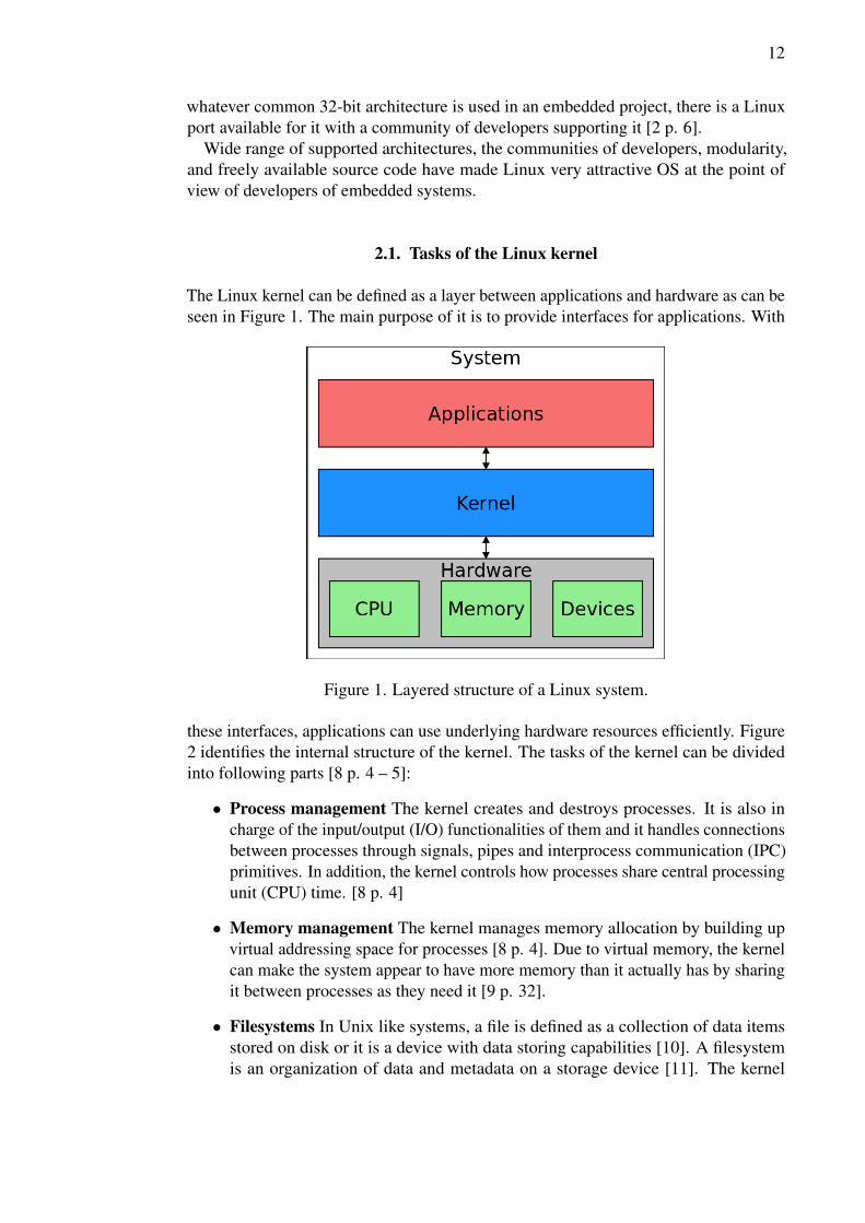
The Linux kernel can be defined as a layer between applications and hardware as can beseen in Figure 1. The main purpose of it is to provide interfaces for applications. With
Figure 1. Layered structure of a Linux system.
these interfaces, applications can use underlying hardware resources efficiently. Figure2 identifies the internal structure of the kernel. The tasks of the kernel can be dividedinto following parts [8 p. 4 – 5]:
• Process management The kernel creates and destroys processes. It is also incharge of the input/output (I/O) functionalities of them and it handles connectionsbetween processes through signals, pipes and interprocess communication (IPC)primitives. In addition, the kernel controls how processes share central processingunit (CPU) time. [8 p. 4]
• Memory management The kernel manages memory allocation by building upvirtual addressing space for processes [8 p. 4]. Due to virtual memory, the kernelcan make the system appear to have more memory than it actually has by sharingit between processes as they need it [9 p. 32].
• Filesystems In Unix like systems, a file is defined as a collection of data itemsstored on disk or it is a device with data storing capabilities [10]. A filesystemis an organization of data and metadata on a storage device [11]. The kernel

13
Figure 2. Internal structure of the kernel.
builds a structured filesystem on top of unstructured hardware [8 p. 4]. This fileabstraction is used by the whole system. Linux can organize data on the physicalmedium several different manners [8 p. 4]. These manners are called filesystemtypes. Supported filesystems in Linux include ext4, FAT, procfs, and severalothers [10].
• Device control Every device in the system, excluding a processor and memory,needs specific software in order to be usable. That software is called a devicedriver. The kernel uses a device driver to map control operations to a physicaldevice. [8 p. 5]
• Networking Most of the networking operations are not specific to a process. Thekernel has to collect, identify and dispatch network packets before they can besent to a process. Additionally, the kernel is in charge of routing and addressresolution issues, and it also take care of delivering data packets across networkinterfaces and programs. [8 p. 5]
2.2. Kernel modules
The Linux kernel is a monolithic kernel. This means that it is a single large program. Allfunctional components of the kernel have access to internal data structures and routines.Nevertheless, the functionality of the kernel can be extended by kernel modules. Kernelmodules are pieces of code that can be linked and unlinked into the kernel duringthe execution. A loaded kernel module becomes a part of the kernel as the normalkernel code. When loading a kernel module, the module is registered to the kernel anddata-structures and functionalities of it are attached to the kernel. [2 p. 81] [12 p. 90]

14
The purpose of kernel modules is to provide services and features to applications.Nevertheless, kernel modules are not application programs. Therefore, they can not beexecuted on their own. Rather, modules are invoked by an application program. Mostly,kernel modules are used for device drivers and pseudo-device drivers such as peripheraldrivers or filesystems. [2 p. 85] [13]
Usually, there are no modules in production embedded Linux systems since typicallyit is well-known what hardware the system have to support [2 p. 81]. Nonetheless,from the point of view of a kernel developer, kernel modules provides an efficientmethod in order to develop new features and functionalities. Thus, a piece of codeunder development can be loaded as a module to the kernel, so it can be tested withoutneed to compile the whole kernel [12 p. 189]. In addition, the debugging of the pieceof code defined as a module is easier than to debug the same piece of code when it isbuilt-in to the kernel.
2.3. Device drivers
A piece of code which defines mechanisms how to use a physical device is called adevice driver. A device driver provides an internal programming interface for usinga physical device without a need to understand how a device actually works. Thereare three fundamental types of devices in the Linux kernel. These types are characterdevices, block devices and network interfaces. It is noticeable, that the division is notinflexible; a programmer may implement many types of drivers in the same piece ofcode. Additionally some types of drivers, such as universal serial bus (USB) modulesand serial modules, use an additional layer of kernel support functions. For example,USB modules work with the USB subsystem of the kernel, but the device itself is stillshowed up in the system as one of the fundamental driver type. [8 p. 2, 5 – 7] [12 p.189]
A character device is a device which can be accessed as a stream of bytes. However,character devices are not the same as files; most of them are data channels and theycan be only accessed sequentially whereas a regular file can be accessed anywhere. Acharacter driver implements at least opening, closing, writing and reading functionalitiesfor a character device. [8 p. 6]
Devices which can host a filesystem are called block devices. These kind of devicesare in example disks. Linux allows applications to read and write any number of bytesthrough a block driver. Block devices and character devices differ in the way how theLinux kernel manages their data internally. This difference is transparent to a user. Bothcharacter devices and block devices are accessed by filesystem nodes in the devicedirectory /dev. [8 p. 7]
A network interface can be a hardware device or a software device. The purpose ofthe network interface is to send and receive data packets from other hosts. A networkdriver implements a network interface. Communication between network interfacesand the kernel is handled by the network subsystem of the kernel. Network drivers areindependent of network protocols; they only handle packets. [8 p. 7]
15
2.4. Configuring and building the kernel
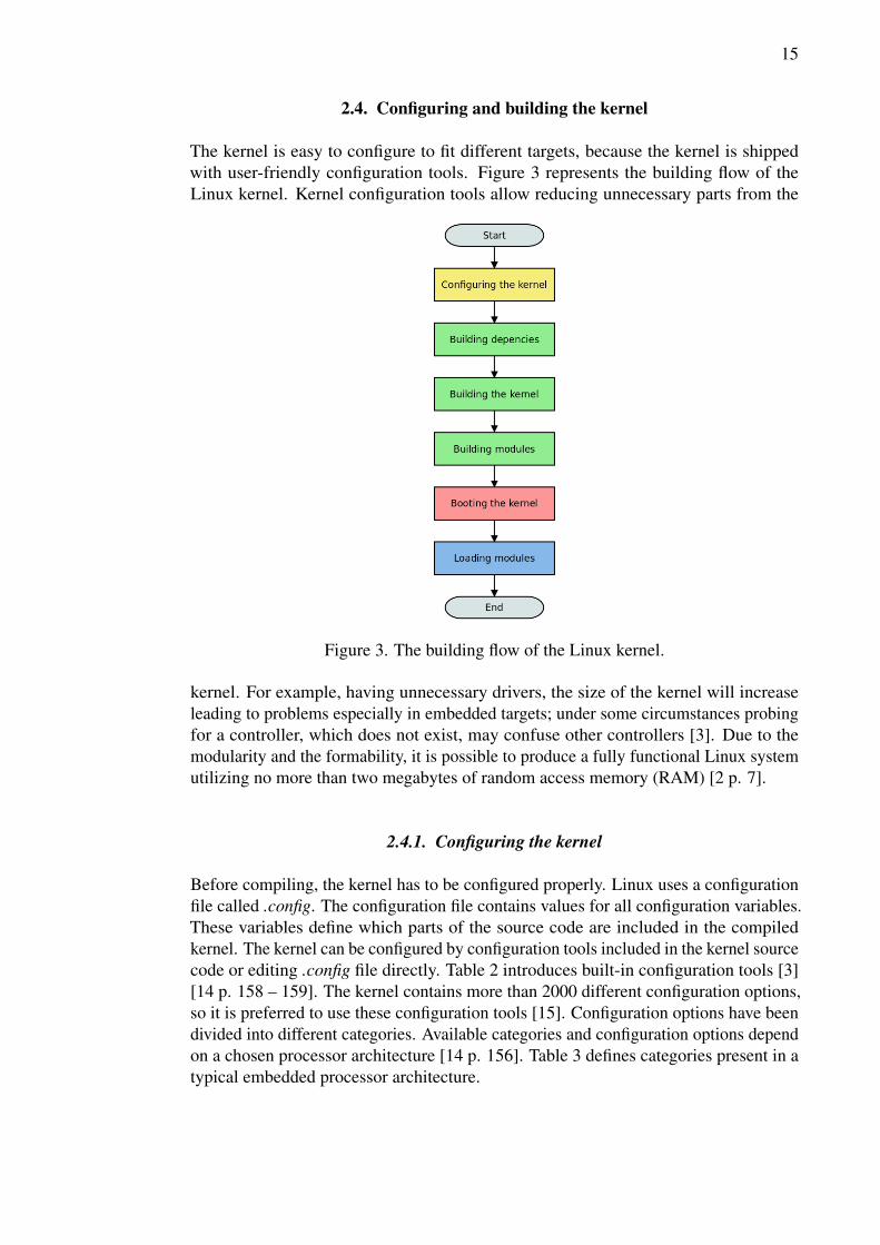
The kernel is easy to configure to fit different targets, because the kernel is shippedwith user-friendly configuration tools. Figure 3 represents the building flow of theLinux kernel. Kernel configuration tools allow reducing unnecessary parts from the
Figure 3. The building flow of the Linux kernel.
kernel. For example, having unnecessary drivers, the size of the kernel will increaseleading to problems especially in embedded targets; under some circumstances probingfor a controller, which does not exist, may confuse other controllers [3]. Due to themodularity and the formability, it is possible to produce a fully functional Linux systemutilizing no more than two megabytes of random access memory (RAM) [2 p. 7].
2.4.1. Configuring the kernel
Before compiling, the kernel has to be configured properly. Linux uses a configurationfile called .config. The configuration file contains values for all configuration variables.These variables define which parts of the source code are included in the compiledkernel. The kernel can be configured by configuration tools included in the kernel sourcecode or editing .config file directly. Table 2 introduces built-in configuration tools [3][14 p. 158 – 159]. The kernel contains more than 2000 different configuration options,so it is preferred to use these configuration tools [15]. Configuration options have beendivided into different categories. Available categories and configuration options dependon a chosen processor architecture [14 p. 156]. Table 3 defines categories present in atypical embedded processor architecture.

16
Table 2. Linux kernel configuration toolsmake config Plain text interface. Each options
asked one by one. Uses .config fileto set default values, if it is present.
make menuconfig Text based color menus, radiolistsand dialogs. Uses .config file to setdefault values, if it is present.
make nconfig Enhanced text based color menus.make xconfig X windows (Qt) based configuration
tool.make gconfig X windows (Gtk) based configura-
tion tool.make oldconfig Sets all configuring options based
on the contents of the existing .con-fig file and asks about new configsymbols.
make silentoldconfig Like above, but avoids cluttering thescreen with questions already an-swered. Additionally updates thedependencies.
make defconfig Create a .config file by using the de-fault symbol values depending onthe architecture.
make allyesconfig Create a .config file by setting sym-bol values to ’y’ as much as possi-ble.
make allnoconfig Create a .config file by setting sym-bol values to ’n’ as much as possi-ble.
make randconfig Create a .config file by setting sym-bol values to random values.
2.4.2. Building the kernel
Compiling the kernel involves several steps as can be seen in Figure 3. These stepsare building kernel dependencies, building the kernel, and building kernel modules.Building the kernel dependencies is needed, because most files in the source code ofthe kernel depend a number of header files. The list of header files, called .depend, isgenerated when the kernel dependencies are built. That list is read during compilationand needed header files are compiled according to it. [14 p. 161]
The configured kernel is compiled by gcc. Nonetheless, gcc is not used directly, butvia a program called make. The compilation process uses Makefiles to define rules forgcc and make. Makefiles needed in the compilation are delivered with the source codeof the kernel.

17
Table 3. Embedded Linux kernel configuration sectionsProcessor support Supported processors and processor
related options i.e processor typeand features.
General setup General options.Platform support Supported platforms.Kernel options General kernel options such as a
memory model and a preemptionmodel.
Bus options Defines supported buses.Networking support Defines the networking support of
the kernel.Device drivers Contains all drivers built-in the ker-
nel.File systems Defines supported filesystems.Library routines Contains options for library routines
such as checksum calculation func-tions.
Kernel hacking Contains options for kernel debug-ging and statistics.
Security options Defines support for cryptographicapplication programming interface(API) and virtualization.
The compilation process creates a compressed kernel image. If any parts of the kernelhave configured as a module, these modules need to be compiled separately by usingmake modules command [3].
2.4.3. Booting the compiled kernel
One of the major differences between embedded systems and general purpose computersis in the boot process of the system. There is a program called basic input output system(BIOS) on a general purpose computer. BIOS is executed when a computer is poweredup. The purpose of BIOS is to initialize hardware and load an OS. Embedded systemsdo not have BIOS. The OS is loaded by a bootloader. The task of the bootloader is toinitialize critical hardware such as memory and I/O-devices. It also reserves resourcessuch as memory and interrupts needed by the OS. When an OS is started, the executionof the bootloader is stopped.
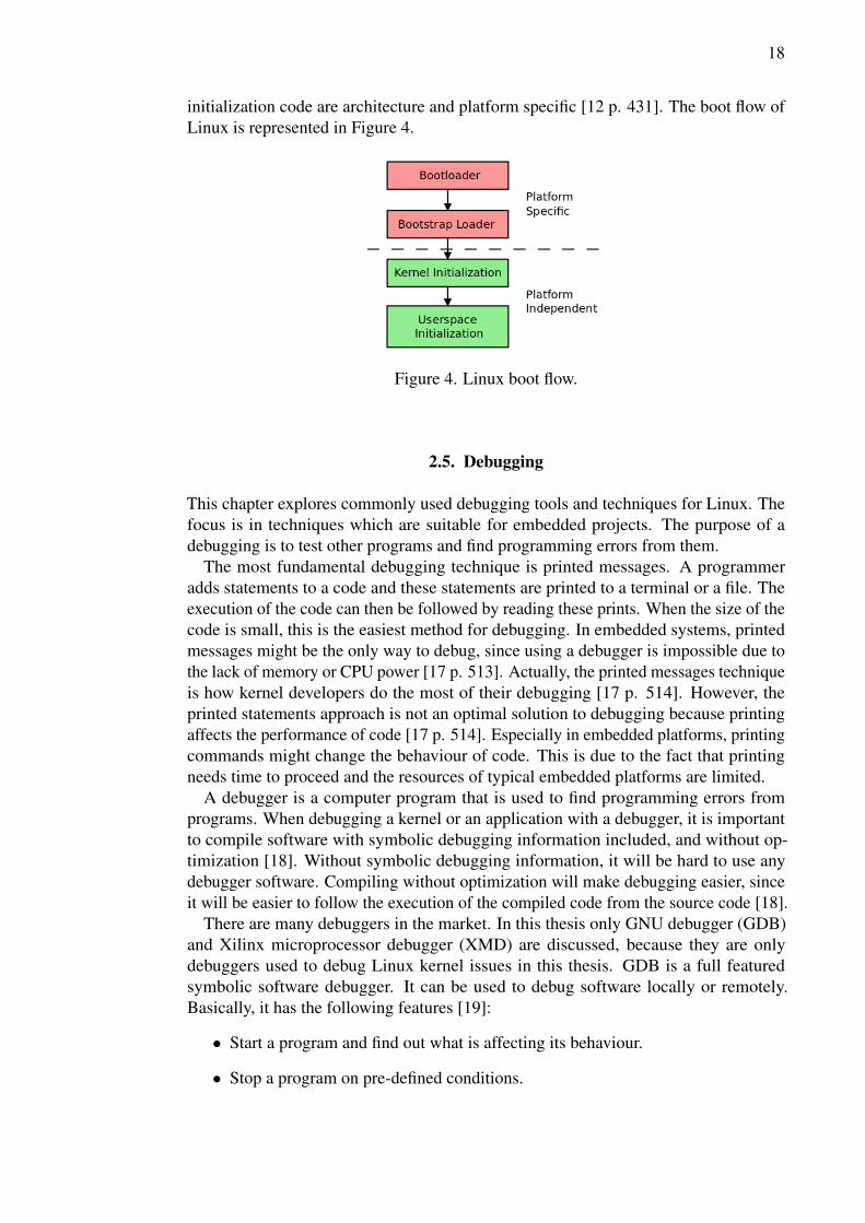
In case of Linux, the bootloader passes the control to the bootstrap loader of thekernel which loads the compiled Linux kernel image to memory and gives the controlof the system to Linux [12 p. 109, 431]. Platform initialization code which determineswhat kind of platform the kernel is running on, is executed at this point [12 p. 426].From there, the kernel performs the checks on system hardware, enumerates devicesand mounts the root filesystem [16]. After that, the kernel calls init function, whichinitializes the userspace of Linux [16]. It is noticeable that the bootloader and platform
18
initialization code are architecture and platform specific [12 p. 431]. The boot flow ofLinux is represented in Figure 4.
Figure 4. Linux boot flow.
2.5. Debugging
This chapter explores commonly used debugging tools and techniques for Linux. Thefocus is in techniques which are suitable for embedded projects. The purpose of adebugging is to test other programs and find programming errors from them.
The most fundamental debugging technique is printed messages. A programmeradds statements to a code and these statements are printed to a terminal or a file. Theexecution of the code can then be followed by reading these prints. When the size of thecode is small, this is the easiest method for debugging. In embedded systems, printedmessages might be the only way to debug, since using a debugger is impossible due tothe lack of memory or CPU power [17 p. 513]. Actually, the printed messages techniqueis how kernel developers do the most of their debugging [17 p. 514]. However, theprinted statements approach is not an optimal solution to debugging because printingaffects the performance of code [17 p. 514]. Especially in embedded platforms, printingcommands might change the behaviour of code. This is due to the fact that printingneeds time to proceed and the resources of typical embedded platforms are limited.
A debugger is a computer program that is used to find programming errors fromprograms. When debugging a kernel or an application with a debugger, it is importantto compile software with symbolic debugging information included, and without op-timization [18]. Without symbolic debugging information, it will be hard to use anydebugger software. Compiling without optimization will make debugging easier, sinceit will be easier to follow the execution of the compiled code from the source code [18].
There are many debuggers in the market. In this thesis only GNU debugger (GDB)and Xilinx microprocessor debugger (XMD) are discussed, because they are onlydebuggers used to debug Linux kernel issues in this thesis. GDB is a full featuredsymbolic software debugger. It can be used to debug software locally or remotely.Basically, it has the following features [19]:
• Start a program and find out what is affecting its behaviour.
• Stop a program on pre-defined conditions.

19
• Find out what has happened when a program has stopped.
• Examine and change a state of the stopped program.
• Run a program step-by-step.
GDB can be used either locally or remotely. When debug embedded software, using aremote debugging is often the only way to use GDB, because it is not possible to useGDB directly on an embedded platform due the lack of the memory or CPU power.Even if it is possible to use GDB locally in a target system, using a remote debuggingis often reasonable. For example, when debug an OS of an embedded system, a localdebugger crashes every time when the system crashes. Figure 5 illustrates a remotedebugging with GDB [2 p. 67].
Figure 5. Remote debugging with GDB.
XMD is a debugger for Xilinx FPGA systems. It can be used to debug booting issuesof Linux, since it can access to the main memory and registers, and shows the contentsof them. XMD can also run a code step by step. One of the features of XMD is thatit has a built-in tool command language (TCL)-parser. TCL is a scripting languagewith industry standard features. It is possible to use all the functionality of XMDvia TCL-scripts. This combination provides very useful debugging possibilities likeshowing debug symbols read from registers or memory as a human readable formatinstead of hex code. In addition, XMD can be connected to GDB. In embedded softwareprojects, remote debugging is a needed feature, because it makes possible to use anormal personal computer (PC) for debugging. XMD starts GDB server automaticallyafter the user connects to the target processor. After that, debugging can be done usingGDB client running in a PC. Additionally, XMD provides an option to debug eachprocessor in an isolated and non-intrusive fashion in a multiprocessor system. Figure 6shows the connectivity of XMD. [18] [20] [21]

20
Figure 6. XMD targets.
A debugging of Linux can be divided into two parts: a pre-boot debugging and arun-time debugging. The pre-boot debugging is needed when the kernel does not bootproperly or it crashes before it is fully loaded. The run-time debugging is instead focusedon finding problems from a fully loaded kernel, where are misbehaving or crashingmodules such as drivers. The following sections introduce debugging techniquescommonly used in the embedded software development.
2.5.1. Pre-boot debugging
When porting Linux to an embedded platform, it is common to encounter issues bootingthe kernel. This can be due various reasons such as an improper kernel configuration,inconsistencies in the hardware description, and various other reasons. If the Linuxkernel crashes before it is fully booted, it will not write any log file or print any messagesto standard output (stdout) or standard error (stderr). This makes debugging difficult,because many tools generally used to debug Linux issues are not available during theboot process. [22]
In cases like this, the only option is to use some debugging software such as GDB.With a debugger, it is possible to set breakpoints to the code and stop the execution ofthe code, when the breakpoint is reached. This helps a developer to find out why thecrash is happening.
Another approach to debug pre-booting issues is to execute a kernel step by step tillthe crash occurs, and then read the contests of registers and main memory. Usually,Linux has generated debugging information at this point and stored it to a memory orregisters, but it has crashed before writing information to a log file. Debuggers likeXMD can read the contents of the main memory and registers even after a crash of thekernel. In this thesis, XMD was used as the main debugger for kernel booting issuesdebugging.
XMD uses joint test action group (JTAG) for communication with the target board.It is ran on the host computer. First, when XMD is started, it connects itself to the

21
processor which runs software wanted to debug. Then, software, in this case Linux, isloaded in the target board. At this point, XMD shows memory regions where softwareis loaded. The next step is to start the execution of software. Software can be executedstep by step, but it is impractical to run large software like Linux step by step due to thegreat number of needed steps. Better method is to run software normally without stepsand observe the values of registers in order to notify when execution hangs. If valuesdo not change, then there is a high probability that software is hanged. If there are fatalerrors in software under debugging which lead to a crashing of software, XMD stopsthe execution of software. When a hang or a crash occurs during debugging, XMD isstill able to read the values of registers and main memory. For example, the system logof Linux can be read from the memory.
With TCL scripts, it is possible to convert the hex values of registers and memory to ahuman readable form. If the system log of Linux is not available, it indicates that Linuxdid not boot properly. If the system log is available, it is easy to find out why executionis stopped, since there is a clear error message in the system log. However, it is possiblethat Linux is booted properly, but it crashes or hangs before it writes the system log.In these cases, the cause of the issue can be found by reading a program stack. Again,with TCL script, the hex values of the program stack can be converted to a text form.The program stack contains the names of functions executed before a crash or a hangoccurs, so with this method, it is easy to find out which function is causing the issue.
2.5.2. Run-time debugging
Typically, the development of new kernel features or functionalities, such as devicedrivers, is done by using kernel modules; a piece of code under development is definedas a module in the kernel configuration process. This is done because debuggingmodules is easier than debugging new code which is defined as a solid part of the kernel.
Modules can be loaded and unloaded to the kernel after it is booted up. Therefore, itis possible to load the module under development and see if it is working properly. Ifthe module is misbehaving, then it can be unloaded, errors can be fixed and then it ispossible to load the recompiled module in the kernel without booting the kernel. In thisthesis, new kernel drivers were developed using this approach.
Typically, the most of embedded system software is not related to hardware. There-fore, it is possible to debug the most of the code without hardware [2 p. 73]. This makesa developing process faster, since most of the software development can be separatedfrom a hardware development.
2.6. Embedded Linux distributions
A Linux distribution is a software system built on top of the Linux kernel. Distributionsinclude a set of software applications, utilities, libraries and documentation. There isa wide variety of Linux distributions for many different purposes available. Due tothe high modularity of the Linux kernel and wide open-source software support, thereare distributions from fully featured desktop, server, laptop and tablet distributions tominimal embedded distributions. A purpose of distributions is to provide a software
22
system which is easy to setup and maintain. An option for distributions is to manuallyset up a system and compile, install and maintain needed software for it.
The main difference between embedded distributions and desktop distributions is aused standard C-library. Desktop distributions use a standard GNU C-library (glibc),whereas embedded distributions use more lightweight alternatives such as uClibc anddiet libc. The standard C-library is a collection of header files and library routines fortasks like string handling, mathematical computations and I/O processing. Basically, allC programs need a standard C-library. The standard glibc is the most common C-libraryfor Linux systems. Nonetheless, it is not used in embedded systems, because of the sizeof it [14 p. 135]. The most important C-library alternatives are uClibc and diet libc.They have been implemented to offer sufficient functionality in small size [14 p. 135].
The uClibc library is developed for an embedded Linux system. It has functionalitysimilar to glibc though uClibc does not include functions and features which are notcommonly used. Typically, glibc based applications can be ported to use uClibc byrecompiling them. UClibc supports shared libraries and threading. [14 p. 135] [23]
Diet libc is a standard C-library implementation that is optimized for small size. Itsupports many architectures including performance optimization with enhanced RISCperformance computing (PowerPC) and advanced RISC machines (ARM). Diet libccan be used to create small binaries which are statically linked. However, it can be usedas a shared library on some platforms. [24] [14 p. 140]
Typically, the hardware of embedded systems varies both in terms of design andcapability. Moreover, many embedded devices may contain closed-source softwaresuch as firmware. Thus, it is difficult to design a general-purpose embedded distribution.However, there are a range of projects supporting the development of embedded Linux.Not all these projects can be considered as a traditional distribution, but they still aim tothe same goal; bringing better Linux support for embedded systems. These projects canbe divided into four category: commercial distributions, meta-distributions, miniaturedesktop distributions, and complete software stacks. [25]
2.6.1. Commercial embedded Linux distributions
Several commercial vendors are shipping embedded Linux distributions. These distri-butions are mainly used by embedded device manufacturers in order to get guaranteedintegration support, a quicker time-to-market and enhanced development tools. Themost prominent commercial embedded distributions are MontaVista Linux [26] andWind River Linux [27]. However, a number of other commercial embedded distributionsexist. [25]
2.6.2. Meta-distributions
A number of configurable build tools are developed to mitigate creating a Linux systemfor an embedded device. These tools provide the convenience of a framework withflexibility of selecting, configuring and building sources by hand. Tools of this kindare called meta-distributions since they are not traditional distributions; they are toolswhich are used to make a distribution. [25]

23
Buildroot is a popular build framework. Basically, Buildroot is a set of Makefilesand patches. It can generate a cross-compilation toolchain, a root filesystem, a Linuxkernel image and a bootloader image. It supports various processor architectures suchas ARM, PowerPC and million instructions per second (MIPS). Buildroot can be usedfor one or several of these steps independently. It also has support for several hundredsof userspace applications and libraries. Buildroot is configured via similar interfaces asthe Linux kernel since it uses menuconfig, gconfig and xconfig configuration tools [28].
OpenEmbedded is also a build framework for embedded Linux. It offers cross-compile environment which can be used to create a complete embedded Linux distribu-tion. OpenEmbedded is easy to customize for different purposes and it supports manyhardware architectures. Furthermore, it provides tools for speeding up the process ofrecreating a base system after modifications have been made. OpenEmbedded supportsa wide variety of software including GIMP toolkit (GTK+), Qt and Java. [29]
Scratchbox differs from the approaches of Buildroot and OpenEmbedded. It providesa chrooted environment, where build tools produce a cross-compiled code. With Scratch-box, there is no need to configure software packages suitable for cross-compilation,since packages can be built as native ones. Scratchbox also has Qemu integration. Qemucan emulate platforms, so it can be used to run a cross-compiled code. This is a usefulfeature, because with Qemu, it is possible to test software before actual hardware isavailable. Scratchbox supports glibc and uClibc as C-library choices. [25] [30]
2.6.3. Miniature desktop distributions
Projects like Emdebian [31] and Gentoo Embedded [32] aims to make a desktop dis-tribution suitable for an embedded device. These projects slim down general-purposedistributions to fit embedded devices. They provide a heavily modified set of softwarepackages ported to embedded architectures with a more fine-grained control over pack-age selection, size, dependencies and content. Moreover, they have a package managersoftware which mitigates installing, maintaining and removing software packages.[25]
2.6.4. Complete software stacks
Several projects aim to create application-specific software stacks for embedded plat-forms. For example, OpenWRT [33] and Tomato [34] provides network router firmwaresand Android [35] and Mer [36] are geared toward mobile phones and internet tablets.These projects offer a software platform suitable for certain use cases. In other words,they are distributions for device manufacturers rather than end-users. [25]
2.6.5. Comparison of embedded Linux distributions
Commercial embedded Linux distributions provide for example guaranteed integrationsupport and enhanced development tools. However, using a commercial distributionis not free of charge. Thus, they are not very suitable for using in non-commercialdevices. Minimal distributions are free instead. They are suitable for use cases where
24
it is important to install and maintain large number of packages, due to the packagemanager system they have. However, miniature distributions are not so flexible thanmeta-distributions. Although meta-distributions typically demand more work thanminiature distributions to produce a working Linux system, they offer more options tocustomize the system. Therefore, meta-distributions are popular when porting Linux tocustom platforms. Custom software stacks differ other distribution types by providingsolutions for well-defined use cases. For example, OpenWrt implements a feature-richsystem for routers and Mer is focused on mobile phones and internet tablets. Due to thenarrow scope of complete software stacks, they are not suitable for other platforms.
2.7. Busybox
Busybox melds small versions of numerous common UNIX utilities into a singleexecutable. It provides implementations for most of the commands usually find outfrom GNU’s not Unix (GNU) utilities such as coreutils and fileutils. Althought, Busyboxdoes not support all the features provided by commands it replaces, but options that areincluded are sufficient for most typical uses and they offer expected functionality. [37]
Busybox is extremely modular and therefore it can be customized for needs ofembedded Linux systems; commands and features can be included or excluded duringthe compiling process and several utilities, such as vi, can be configured in theirfunctionality [37]. Thus, with Busybox it is possible to create an optimally adapted setof commands for a Linux system in an embedded platform.
2.8. Porting Linux
The Linux source tree contains ports for more than 20 different processor architecturesand numerous different boards. If Linux has support for a processor architecture ofa custom board, it is not difficult to port Linux to it. Basically, it demands that thereis a piece of code which initializes the hardware of the custom board. Additionally,board-specific data has to deliver to the kernel. Typically, this is done by a bootloader,so there has to be the bootloader ported to the target platform in order to port Linux.The Linux porting flow is represented in Figure 7. [12 p. 431]
2.8.1. Organization of the Linux source tree
Architecture-specific code is stored in .../arch-directory in the Linux source tree. Thisdirectory contains architecture-dependent code of the Linux kernel including a memorymanagement code, a number of kernel features and boot-subdirectory, which is usedto build a specific bootable target for certain architecture. There is also a configs-subdirectory in the .../arch-directory. This directory includes in default configurationsfor each supported hardware platform: each one of the entries in this directory representsa specific port to a hardware platform. Some of the architecture branches contains alsoa platforms-subdirectory containing platform-specific code. These directories containall files needed to modify in order to port Linux to a custom platform. [12 p. 422]

25
Figure 7. Linux porting flow.
2.8.2. Porting Linux to a Xilinx FPGA board
PowerPC is a processor architecture developed by IBM, Apple and Motorola. It is awell-established architecture that has originally been used in a PC, but nowadays it isalso popular in embedded systems due to an excellent power/performance ratio andlow heat dissipation. Term PowerPC Linux is defined as the Linux kernel running on aPowerPC processor. [38]
Most of the kernel code is independent of processor architectures [2 p. 73]. The maindifference between x86 and PowerPC architectures is in the boot process of the systemas mentioned in section 2.4.3. PowerPC Linux need to be informed about the platformit is running on [39]. This can be done by passing a device-tree to the kernel duringthe boot. The device-tree is a data-structure which describes the hardware in a system[40]. Basically, the device-tree is a tree of nodes. These nodes contain two or morenamed properties such as a name and a physical address of the unit [41]. The kerneluses device-tree data to find and register devices in the system [39]. It is the task of thebootloader to pass device-tree to the kernel. Thus, the bootloader has to support thisfeature.
Many Xilinx FPGAs, such as Virtex-II Pro and Virtex-4 FX platforms FPGAs, havePowerPC processors embedded in the chip [42] [43]. The second generation WARPboard, which is the target board in this thesis, includes a Xilinx Virtex-4 FX FPGA. InXilinx FPGA boards, the device-tree is generated according to information read fromthe system.mhs file [41], which defines intellectuel property (IP) cores and parametersof them used in the FPGA hardware design. Linux requires that at least a processor, asystem bus, main memory, and a storage device for a filesystem have to be present in

26
the target system, so these devices need to be defined in the FPGA hardware design.Otherwise, it is not possible to run Linux in the target.
In order to produce a working kernel for a Xilinx FPGA board, Linux is configuredto support devices mentioned in the device-tree. The main tree of the kernel sourcecode does not contain device drivers for all devices present in Xilinx FPGA boards.Therefore, it is recommended to use the kernel tree of Xilinx [44]. It contains additionaldevice drivers and patches which are not yet accepted to the main kernel tree, but stillprovide support for several devices and IP cores used in Xilinx FPGA boards [45].
27
3. WARP DEVELOPMENT PLATFORM
WARP is a programmable wireless platform developed by Rice University, USA. It isbeing actively used for research in many areas like physical, MAC and network layeralgorithms, routing, and cognitive radios as can be seen in [46] [47] [48] [49]. It hasresulted in more than 75 publications and it is in use in more than 100 research groups.
The main purpose of WARP is to provide a scalable and extensible platform forresearching wireless networks. Due the open nature of WARP, it is possible to programphysical, MAC, and network layer protocols on a single platform. [50]
3.1. Architecture
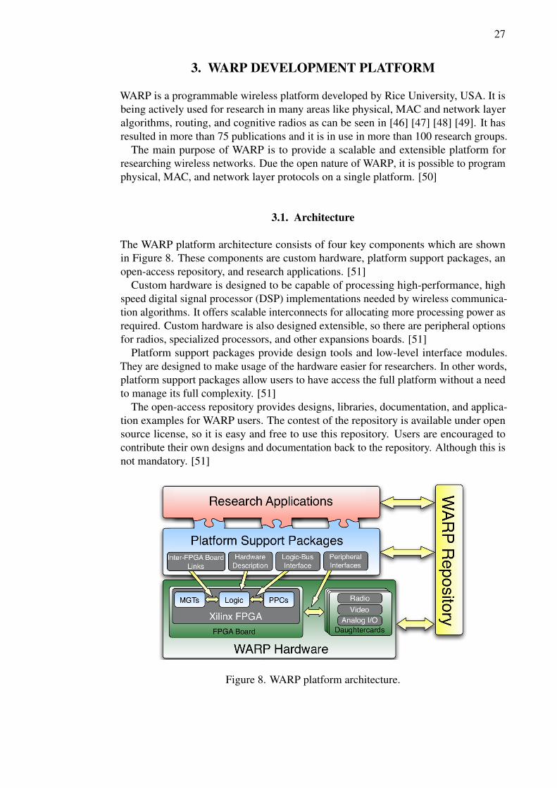
The WARP platform architecture consists of four key components which are shownin Figure 8. These components are custom hardware, platform support packages, anopen-access repository, and research applications. [51]
Custom hardware is designed to be capable of processing high-performance, highspeed digital signal processor (DSP) implementations needed by wireless communica-tion algorithms. It offers scalable interconnects for allocating more processing power asrequired. Custom hardware is also designed extensible, so there are peripheral optionsfor radios, specialized processors, and other expansions boards. [51]
Platform support packages provide design tools and low-level interface modules.They are designed to make usage of the hardware easier for researchers. In other words,platform support packages allow users to have access the full platform without a needto manage its full complexity. [51]
The open-access repository provides designs, libraries, documentation, and applica-tion examples for WARP users. The contest of the repository is available under opensource license, so it is easy and free to use this repository. Users are encouraged tocontribute their own designs and documentation back to the repository. Although this isnot mandatory. [51]
Figure 8. WARP platform architecture.

28
3.2. Hardware
In this thesis, the scope is in the WARPv2 board, also known as the WARP boardversion 2.2. This version is designed around a Xilinx Virtex-4 FPGA [43]. Figure 9introduces the devices and I/O ports of WARP board version 2.2. [50]
Figure 9. WARP board overview.
3.2.1. FPGA
The WARPv2 is built around a Xilinx XC4VFX100FFG1517-11C Virtex-4 FPGA. Theresources of this FPGA are shown in Table 4. [50] [43]
Table 4. FPGA overviewPart XC4VFX100Package FFG1517Speed grade 11Temperature range C (commercial)Logic slices 42kDSP48 slices 160Block RAMs 376PowerPC cores 2Tri-mode Ethernet MACs 4
3.2.2. Power
The WARPv2 board requires external 12 V power supply. Several different voltagelevels are needed for FPGA and peripheral devices. The board uses switching voltageregulators to produce required voltage levels. [50]

29
3.2.3. Memory
The WARPv2 board has on-chip memory and double data rate version 2 (DDR2) smalloutline dual in-line memory module (SO-DIMM) slot for external memory. The Virtex-4 FX100 FPGA provides 6,7 Mb on-chip memory. This memory consists of 376 piecesof 18 kb RAM blocks. It is possible to extend on-chip memory using logic slicesof FPGA as RAM. Xilinx calls this distributed memory. The maximum amount ofdistributed memory of the FPGA in WARP board is 659 kb. [50] [43]
The second generation WARP board is supplied with 2 GB DDR2 SO-DIMM memorymodule which is connected to an external memory slot. The FPGA can control thismemory via DDR2 memory controller called multi-port memory controller (MPMC)[52] provided by Xilinx. [50]
3.2.4. I/O –devices
There is a variety of interactive I/O –devices in WARPv2. Following subsectionsintroduce these devices.
SystemACE
The configuration process of the WARPv2 board can be managed via Xilinx’s systemadvanced configuration environment (SystemACE) CompactFlash (CF) chip. Thischip provides an interface between the FPGA and a standard CF slot. The FPGA canbe automatically configured by SystemACE, if a CF card is in the CF slot when theWARPv2 board is powered up or the manual reset button is pushed. It is possible tostore one to eight configuration files on the CF card. There is a dual in-line (DIP) switchin the WARP board which can be used to choose the configuration file SystemACE willuse to configure the FPGA. Configuration files on the CF card have to be in a advancedconfiguration environment (ACE) format, otherwise SystemACE will not recognizethem. [50]
Multi-gigabit transreceivers
The WARPv2 board includes eight multi-gigabit transreceiver (MGT) full-duplextransceiver interface. These MGTs are divided into three different types: high speedserial data connection (HSSDC2), serial advanced technology attachment (SATA), andsmall form-factor pluggable (SFP). Each type has its own purpose, for example, SFPtype MGT is meant for addon modules such as an extra Ethernet module. [50]
User I/O
There are several interactive I/O devices in the WARPv2 board which are intended todebugging and observing purposes. User I/O devices can be managed via custom coredeveloped by Rice university. Figure 10 introduces these devices. [50]
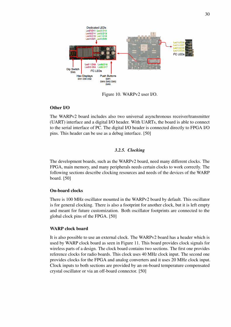
30
Figure 10. WARPv2 user I/O.
Other I/O
The WARPv2 board includes also two universal asynchronous receiver/transmitter(UART) interface and a digital I/O header. With UARTs, the board is able to connectto the serial interface of PC. The digital I/O header is connected directly to FPGA I/Opins. This header can be use as a debug interface. [50]
3.2.5. Clocking
The development boards, such as the WARPv2 board, need many different clocks. TheFPGA, main memory, and many peripherals needs certain clocks to work correctly. Thefollowing sections describe clocking resources and needs of the devices of the WARPboard. [50]
On-board clocks
There is 100 MHz oscillator mounted in the WARPv2 board by default. This oscillatoris for general clocking. There is also a footprint for another clock, but it is left emptyand meant for future customization. Both oscillator footprints are connected to theglobal clock pins of the FPGA. [50]
WARP clock board
It is also possible to use an external clock. The WARPv2 board has a header which isused by WARP clock board as seen in Figure 11. This board provides clock signals forwireless parts of a design. The clock board contains two sections. The first one providesreference clocks for radio boards. This clock uses 40 MHz clock input. The second oneprovides clocks for the FPGA and analog converters and it uses 20 MHz clock input.Clock inputs to both sections are provided by an on-board temperature compensatedcrystal oscillator or via an off-board connector. [50]

31
Figure 11. WARP clock board.
SystemACE CF clocking
The SystemACE CF controller requires a 33 MHz clock and the FPGA needs a copyof this clock. Otherwise, the FPGA can not use the microprocessor interface of theSystemACE controller. That is why there is a 33 MHz oscillator in the WARPv2board. The output of this oscillator is divided to offer this clock both the FPGA and theSystemACE CF controller. [50]
Memory clocking
The second generation WARP board includes a DDR2 SO-DIMM slot. SO-DIMMcan be used via MPMC provided by Xilinx. The clocking of MPMC depends on theconfigurations of MPMC. There are four system clock inputs and one clock for eachpersonality interface module (PIM) in MPMC. [50] [52]
3.2.6. Ethernet
The Virtex-4 FPGA implementation of the MAC layer uses the hardened tri-mode Eth-ernet MAC (TEMAC) and the soft Locallink TEMAC. A physical layer is implementedby using the Marvell 88e111 Gigabit Ethernet physical layer (PHY) [53]. The Ethernetdevice of the WARPv2 boards support speeds 10, 100 and 1000 Mbit/s [50]. TEMACcore supports a media independent interface (MII), a gigabit media independent inter-face (GMII), a reduced gigabit media independent interface (RGMII), a serial gigabitmedia independent interface (SGMII) and an IEEE 802.3z standard for gigabit Ethernet(1000BASE-X) interface. [54]. It is possible to connect two locallink first in first out(FIFO) cores [55] to the TEMAC core, so the TEMAC is able to use two Ethernetinterface at the same time [54]. This is useful functionality, when WARPv2 boardhardware is extended with addon Ethernet modules such as a SFP module connected toa MGT-connector.
32
3.2.7. Daughtercards
The WARPv2 board includes four identical daughtercard slots. Any combination ofdaughtercards can be used, assuming that they fill design specifications. The followingsections introduce daughtercards used in this thesis. [50]
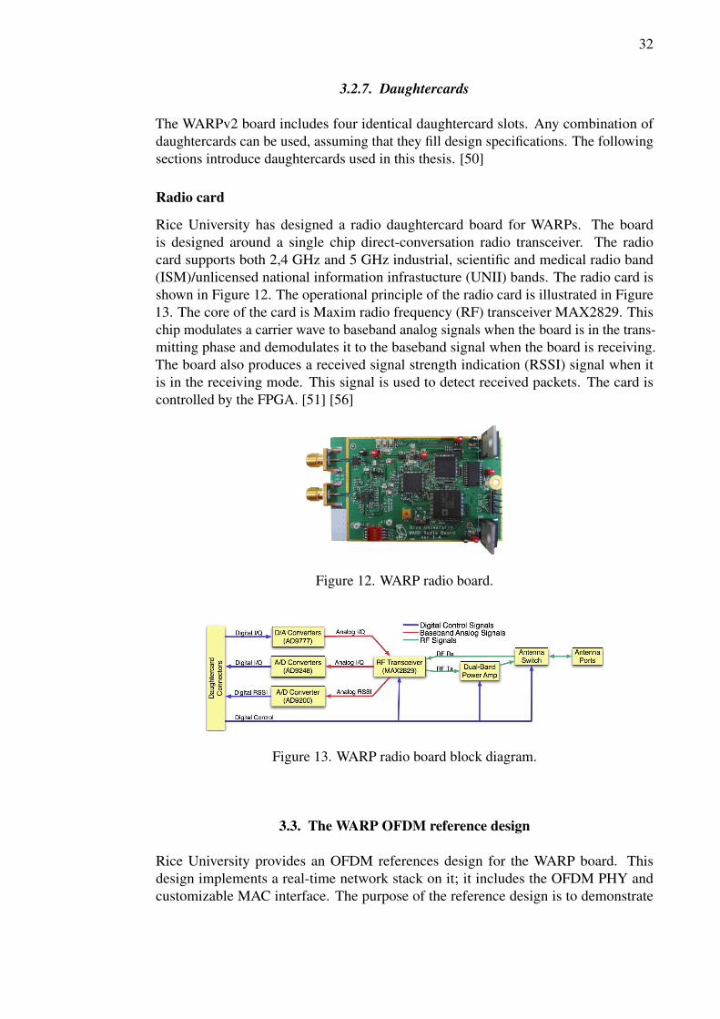
Radio card
Rice University has designed a radio daughtercard board for WARPs. The boardis designed around a single chip direct-conversation radio transceiver. The radiocard supports both 2,4 GHz and 5 GHz industrial, scientific and medical radio band(ISM)/unlicensed national information infrastucture (UNII) bands. The radio card isshown in Figure 12. The operational principle of the radio card is illustrated in Figure13. The core of the card is Maxim radio frequency (RF) transceiver MAX2829. Thischip modulates a carrier wave to baseband analog signals when the board is in the trans-mitting phase and demodulates it to the baseband signal when the board is receiving.The board also produces a received signal strength indication (RSSI) signal when itis in the receiving mode. This signal is used to detect received packets. The card iscontrolled by the FPGA. [51] [56]
Figure 12. WARP radio board.
Figure 13. WARP radio board block diagram.
3.3. The WARP OFDM reference design
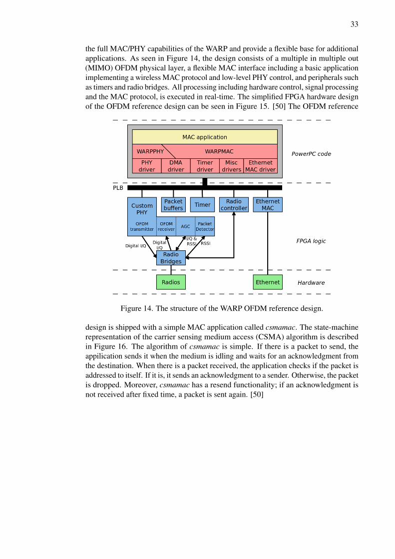
Rice University provides an OFDM references design for the WARP board. Thisdesign implements a real-time network stack on it; it includes the OFDM PHY andcustomizable MAC interface. The purpose of the reference design is to demonstrate
33
the full MAC/PHY capabilities of the WARP and provide a flexible base for additionalapplications. As seen in Figure 14, the design consists of a multiple in multiple out(MIMO) OFDM physical layer, a flexible MAC interface including a basic applicationimplementing a wireless MAC protocol and low-level PHY control, and peripherals suchas timers and radio bridges. All processing including hardware control, signal processingand the MAC protocol, is executed in real-time. The simplified FPGA hardware designof the OFDM reference design can be seen in Figure 15. [50] The OFDM reference
Figure 14. The structure of the WARP OFDM reference design.
design is shipped with a simple MAC application called csmamac. The state-machinerepresentation of the carrier sensing medium access (CSMA) algorithm is describedin Figure 16. The algorithm of csmamac is simple. If there is a packet to send, theappilication sends it when the medium is idling and waits for an acknowledgment fromthe destination. When there is a packet received, the application checks if the packet isaddressed to itself. If it is, it sends an acknowledgment to a sender. Otherwise, the packetis dropped. Moreover, csmamac has a resend functionality; if an acknowledgment isnot received after fixed time, a packet is sent again. [50]

34
Figure 15. The simplified FPGA hardware design of the OFDM reference design.
Figure 16. The state-machine representation of CSMA algorithm.

35
3.4. Design process flow and design tools for FPGA developing
WARPv2 board is designed around the Xilinx Virtex-4 FPGA chip [50]. Xilinx providesa suite of design tools for customizing the hardware logic of the FPGA chip. Tools aredesigned to assist in all phases of the embedded design process as shown in Figure 17[21]. The Xilinx FPGA design process can be divided into four phases:
• Hardware development
• Software development
• Verification
• Device configuration
In a hardware development phase, a hardware platform is created. The hardwareplatform consists of processors and peripherals connected to the processor buses. Thedesign tool stores created hardware specifications to the microprocessor hardwarespecification (MHS) file. A software platform is described in the software developmentphase. This platform consists of a collection of software drivers and an OS. In addition,the software platform includes portions of the Xilinx libraries, such as a networkingstack library, used in the design. The software platform description is stored in themicroprocessor software specification (MSS) file. The next phase in the design processis the verification. Both hardware and software need to be verified. The hardwareplatform can be verified in a hardware design language (HDL) simulator. Simulatingdemands that a simulation model have to be created. Software can be verified by loadingthe design on a supported development board and using a debugging tool to test andverify software. An instruction set simulator or a simplified system simulation modelcan be also used to verify software. The next step after the verification phase is a deviceconfiguration. In this phase, a configuration bitstream is created and downloaded to thetarget FPGA. The bitstream consists of the FPGA design and software. [21]
The following sections introduce tools included in the Xilinx design tool suite. Theoverview about design tools is illustrated in Table 5 [21].
3.4.1. Xilinx Platform studio
Xilinx provides a graphical integrated environment, called Xilinx platform studio(XPS), for creating FPGA designs. With XPS, a user can create software and hardwarespecification flows for systems that contain an embedded processor such as PowerPCor MicroBlaze. It is also possible to build and modify FPGA designs using existing IPcores. With XPS, a user can connect IP cores, such as buses and peripherals, togetherand change the values of the parameters of IP cores. [21]

36
Figure 17. Xilinx embedded design tools architecture.

37
Table 5. Design environmentsDesign Environments
Xilinx Platform Studio(XPS)
An integrated design environment with GUI for creatingcomplete design.
Xilinx Software Devel-opment Kit (SDK)
An integrated design environment with GUI for developmentof software applications.
EDK Command Line A tool to run embedded design flows and tools from a com-mand line.
Hardware DevelopmentThe Base SystemBuilder (BSB) Wizard
The BSB wizard provides a baseline system that can be thencustomize to a complete design.
The Create and ImportPeripheral Wizard
Helps create custom peripherals and import them into repos-itories or XPS project.
Coprocessor Wizard A tool for adding and connecting a coprocessor to a CPU.Platform Generator(Platgen)
A tool for compiling high-level description of embeddedprocess system into an HDL netlist that can be implementedin a target FPGA device.
Software DevelopmentLibrary Generator (Lib-gen)
Creates a software platform with a customized collection ofsoftware libraries, drivers and operating system.
GNU Compiler Collec-tion (GCC)
A tool for compiling and building softaware applicationsbased on the software platform created by the Libgen.
VerificationDebug ConfigurationWizard
Automates common tasks related to hardware and softwaredebug configurations.
Xilinx MicroprocessorDebugger (XMD)
A debugging and software downloading tool for embeddedprocessors in the FPGA.
GNU Debugger (GDB) A software debugging tool. Suitable for debugging softwareon a simulation model and a target device.
Simulation Model Gen-erator (Simgen)
A tool for generating and configuring various simulationmodels, such as behavioral, structural and timing models.
Simulation LibraryCompiler (CompED-KLib)
Compiles simulation libraries for the target simulator.
Bus Functional ModelCompiler (BFM)
Simplifies a verification of hardware components attachedto a bus.
Device ConfigurationBitstream Initializer (Bi-tinit)
Converts a hardware-only bitstream to a new bitstream whichcontains a software application executable.
System ACE File Gen-erator (GenACE)
Generates an ACE-file from a FPGA bitstream, applicationexecutables and data files. The ACE-file can be use to ini-tialize and configurate the FPGA and memories with validprogram or data and bootup the processor.
Flash Memory Program-mer (iMPACT)
A tool for programming a flash device.
38
4. PORTING LINUX TO THE WARP BOARD
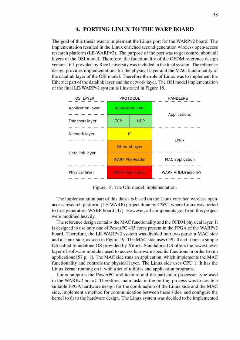
The goal of this thesis was to implement the Linux port for the WARPv2 board. Theimplementation resulted in the Linux enriched second generation wireless open-accessresearch platform (LE-WARPv2). The purpose of the port was to get control about alllayers of the OSI model. Therefore, the functionality of the OFDM reference designversion 16.1 provided by Rice University was included in the final system. The referencedesign provides implementations for the physical layer and the MAC functionality ofthe datalink layer of the OSI model. Therefore the role of Linux was to implement theEthernet part of the datalink layer and the network layer. The OSI model implementationof the final LE-WARPv2 system is illustrated in Figure 18.
Figure 18. The OSI model implementation.
The implementation part of this thesis is based on the Linux enriched wireless open-access research platform (LE-WARP) project done by CWC, where Linux was portedto first generation WARP board [47]. However, all components got from this projectwere modified heavily.
The reference design contains the MAC functionality and the OFDM physical layer. Itis designed to use only one of PowerPC 405 cores present in the FPGA of the WARPv2board. Therefore, the LE-WARPv2 system was divided into two parts: a MAC sideand a Linux side, as seen in Figure 19. The MAC side uses CPU 0 and it runs a simpleOS called Standalone OS provided by Xilinx. Standalone OS offers the lowest levellayer of software modules used to access hardware specific functions in order to runapplications [57 p. 1]. The MAC side runs an application, which implements the MACfunctionality and controls the physical layer. The Linux side uses CPU 1. It has theLinux kernel running on it with a set of utilities and application programs.
Linux supports the PowerPC architecture and the particular processor type usedin the WARPv2 board. Therefore, main tasks in the porting process was to create asuitable FPGA hardware design for the combination of the Linux side and the MACside, implement a method for communication between these sides, and configure thekernel to fit to the hardware design. The Linux system was decided to be implemented

39
by using Buildroot for a root filesystem and cross-compilation toolchain generation,and Busybox for userspace utilities and applications. The decision was made due to thegreat flexibility that the Buildroot and Busybox combination offers.
Figure 19. Functional overview of the Linux enriched WARP system.
4.1. Design flow
The LE-WARPv2 system was designed and implemented as represented in Figure 20.In the design phase, the roles of hardware and software were defined; it was decidedwhich features were going to implement with hardware and which with software. Afterthat, the hardware design was created using Xilinx tools. The software design phasecontained modifications of MAC application and the Linux kernel source code, the Linuxkernel configuration, kernel drivers developing, the root filesystem implementation,and selection and implementation of Linux userspace applications. The steps afterhardware and software designing were building the system and making bootable CFcard. Thereafter, the system was tested, verified and debugged. If tests were not passed,the system was debugged and found errors were fixed. The following sections describeall phases thoroughly.

40
Figure 20. System design flow.
4.2. Hardware design
In order to port Linux to the WARPv2 board, the FPGA design has to contain necessaryhardware. Linux requires at least a processor, a system bus, main memory, and astorage device for filesystems. However, the final goal in this thesis was to implementa LE-WARPv2 system with the functionality of the OFDM reference design version16.1. Therefore, the final FPGA hardware design is based on the OFDM referencedesign. Hardware for Linux was added to this design. A PowerPC 405 core was addedas a processor dedicated to Linux and processor local bus (plb) was added as a systembus. All peripherals controlled by Linux were connected to this system bus. IP corescontrolled by Linux are introduced in Table 6. Additionally, SystemACE and EthernetMAC IP cores were moved from the MAC side to the Linux side by connecting them tothe system bus of Linux. SystemACE controls the usage of a CF card and the filesystemof Linux is stored to CF card. Therefore, it was important that Linux was able to controlSystemACE.
The OFDM reference design does not use external double data rate (DDR) memoryof the WARP board, because the memory footprint of the MAC application is low andbecause external memory is too slow for the requirements of the physical layer. Thus,external memory was decided to be main memory for Linux. This decision simplifiesthe FPGA design since letting both cores to have access to external memory wouldbe demanded either implementing a synchronized memory access method or differentmemory partitions for both cores. There are several methods to connect an externalmemory controller, MPMC, to a processor. For example, MPMC can be connecteddirectly to the processor or it can be connected via plb. In this thesis, MPMC wasconnected to the Linux core via plb of Linux even though using the direct connection

41
Table 6. IP cores controlled by LinuxIP core Description Task of the IP coreppc405_virtex4 PowerPC 405 Virtex-4 Linux CPUplb_v46 Processor Local Bus 4.6 A system bus for Linuxxps_bram_if_cnlr XPS BRAM Controller Boot memory controller
for Linux CPUbram_block Block RAM Block Boot memory for Linux
CPUmpmc Multi-Port Memory
ControllerMain memory interfacefor Linux
xps_central_dma XPS Central DMA Con-troller
DMA controller forLinux
xps_intc XPS Interrupt Con-troller
Interrupt controller forLinux
xps_ll_temac XPS Locallink Tri-mode Ethernet MAC
Ethernet core
xps_ll_fifo XPS Locallink FIFO Interface for Ethernetcore
xps_sysace XPS SystemACE Inter-face Controller
CompactFlash interface
would have offered better performance. The plb based architecture has been chosen dueto simpler implementation and because performance provided by it was sufficient.
Hardware of the OFDM reference design needed to be modified to co-operate cor-rectly with the hardware of the Linux side. A new bus for the MAC side was added toimprove the performance of the MAC side. Memory for a heap and a stack of the MACside was connected to this bus. Other peripherals of the MAC side remained intact.
Two mailboxes and shared memory was added to the final design. Other ends ofmailboxes were connected to the system bus of the MAC side and other end to thesystem bus of Linux. Shared memory was connected as well between the buses of MACand Linux sides. Simplified illustration of the final FPGA hardware design can be seenin Figure 21.
4.2.1. Interprocessor communication
Communication between MAC and Linux sides was implemented with mailboxes anda shared memory block. Generally, the mailbox IP core implements a method to passmessages between one or more senders and receivers. It forms a transmission controlprotocol (TCP)/Internet protocol (IP)-like message channel where messages are queuedin by senders and dequeued by receivers. Mailboxes support both synchronous andasynchronous methods for the reception of messages. In the synchronous method,polling is used to detect new data on the mailbox, whereas the asynchronous methoduses interrupts.
The mailbox IP core provided by Xilinx uses two FIFO buffers; one for transmissionand one for reception. A buffer uses either distributed RAM or block RAM (BRAM)

42
Figure 21. Simplified FPGA hardware design.
and the size of it is configurable. In this thesis, the mailboxes were used to inform otherside about new data in shared memory.
The final FPGA design included shared BRAM memory and two mailboxes. Oneof the mailboxes was dedicated to IP-traffic and one for controlling and logging trafficbetween processor cores. The sizes of mailbox buffers were limited to 16 kB and theyused the synchronous method to pass messages; mailboxes were polled constantly todetect when new data was available in the shared memory. The shared memory wasdivided into fixed size slots, which held any large data that was to be transferred withmessages. The structure of this mailbox-based intercore communication solution isillustrated in Figure 22.
4.2.2. Clocking
The system buses of MAC and Linux sides uses 80 MHz clock frequency. The peripher-als bus uses 40 MHz clock frequency due to the requirement set by the WARP radioboard. The clock frequency of PowerPC processors in the WARPv2 board has to be amultiple of the value of the system bus. The maximum clock frequency supported byPowerPC processors in the FPGA chip of the WARPv2 board is 300 MHz. Although themaximum frequency could not been used due to the clocking demands of the MPMC IPcore. The clocking demands of MPMC forced to use a clock frequency 160 MHz forprocessors.
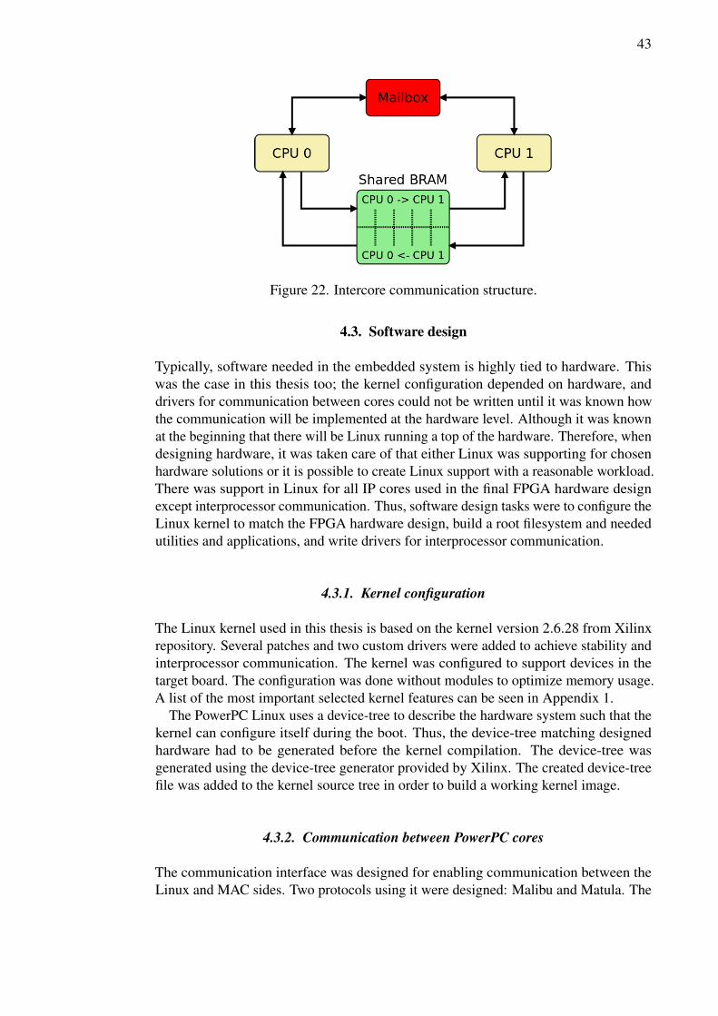
43
Figure 22. Intercore communication structure.
4.3. Software design
Typically, software needed in the embedded system is highly tied to hardware. Thiswas the case in this thesis too; the kernel configuration depended on hardware, anddrivers for communication between cores could not be written until it was known howthe communication will be implemented at the hardware level. Although it was knownat the beginning that there will be Linux running a top of the hardware. Therefore, whendesigning hardware, it was taken care of that either Linux was supporting for chosenhardware solutions or it is possible to create Linux support with a reasonable workload.There was support in Linux for all IP cores used in the final FPGA hardware designexcept interprocessor communication. Thus, software design tasks were to configure theLinux kernel to match the FPGA hardware design, build a root filesystem and neededutilities and applications, and write drivers for interprocessor communication.
4.3.1. Kernel configuration
The Linux kernel used in this thesis is based on the kernel version 2.6.28 from Xilinxrepository. Several patches and two custom drivers were added to achieve stability andinterprocessor communication. The kernel was configured to support devices in thetarget board. The configuration was done without modules to optimize memory usage.A list of the most important selected kernel features can be seen in Appendix 1.
The PowerPC Linux uses a device-tree to describe the hardware system such that thekernel can configure itself during the boot. Thus, the device-tree matching designedhardware had to be generated before the kernel compilation. The device-tree wasgenerated using the device-tree generator provided by Xilinx. The created device-treefile was added to the kernel source tree in order to build a working kernel image.
4.3.2. Communication between PowerPC cores
The communication interface was designed for enabling communication between theLinux and MAC sides. Two protocols using it were designed: Malibu and Matula. The

44
Malibu protocol is used to handle communication between the Linux driver for thewireless network interface and the MAC application running on the MAC core. Instead,the Matula protocol was designed for logging and controlling purposes.
The Warpnet device driver implements the Malibu protocol on the Linux side. In otherwords, it sets up a standard Linux Ethernet interface and sends and receives packetsto the MAC side using a mailbox and shared BRAM memory. The Ethernet interfaceprovided by Warpnet does not contain wireless extensions like wireless local areanetwork (WLAN) drivers do; Linux sees this interface as a regular Ethernet interface.Warpnet probes mailboxes during the kernel boot up, and when the correct mailbox isfound, it sets up the Ethernet interface. MAC and IP addresses are set by using standardLinux tools. The MAC address is sent to the MAC side in order to filter network packetsby a MAC application.
Buffering between Linux and the Ethernet driver is done in the Xilinx XPS LocallinkTEMAC IP core and the Xilinx kernel driver for that IP core. The state-machicerepresentation of interprocessor communication is illustrated in Figure 23. The kerneldriver is connected to the Linux IP stack and it will drop packets when the buffer is full.Buffering between the cores consists of shared memory. The Warpnet driver copiespackets to the shared memory and notifies the MAC side with a mailbox message.Similarly, when receiving packets from the MAC side, packets are copied from theshared memory and delivered to the kernel. The kernel informs the MAC side when ithas copied a packet from the shared memory.
On the MAC side, packets received from Linux are copied to the buffers of the PHYusing direct memory access (DMA). If DMA is busy, the packet is dropped. Alsopackets send to Linux are delivered from PHY buffers to the shared memory usingDMA. If the shared memory is full, the packet is dropped. If DMA is busy, the MACside will wait for it to become available.
The Matula protocol is used to manage log and control messages. The Warptooldevice driver is a character type driver which provides mechanisms to write data to theshared memory between Linux and MAC sides, and notify other side via the mailboxthat there is data in the shared memory. The Warptool device driver implements theMatula protocol. Two userspace applications were developed to use the Warptool devicedriver: warptool and warplogd.
The warptool application can be considered as a front-end to the Warptool devicedriver. It is a userspace application running on Linux and it sends commands to theMAC side. On the MAC side, the MAC application was modified to parse and handlethese commands. Implemented commands included for example setting the frequencyand the channel of wireless radio and adjusting transmit power.
The Warplog daemon, called warplogd, stores log data gathered from the MAC sideto the file on the Linux side. The MAC application was modified by adding log datagathering functions and a function, which writes log data to the shared memory.
4.3.3. Root filesystem
Linux requires a root filesystem in order to use all its services and features. The rootfilesystem is the filesystem mounted at the base of the filesystem hierarchy; any otherfilesystem, such as the proc filesystem, is mounted under the root filesystem. A Linux
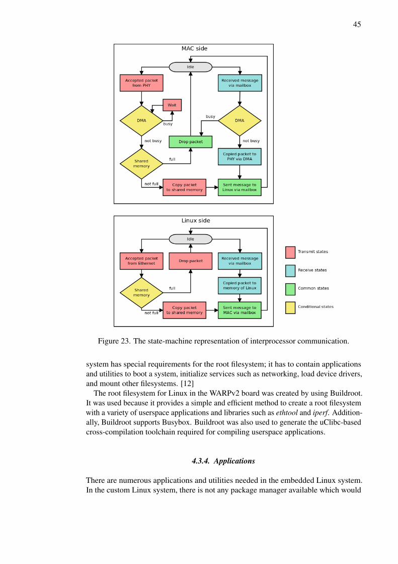
45
Figure 23. The state-machine representation of interprocessor communication.
system has special requirements for the root filesystem; it has to contain applicationsand utilities to boot a system, initialize services such as networking, load device drivers,and mount other filesystems. [12]
The root filesystem for Linux in the WARPv2 board was created by using Buildroot.It was used because it provides a simple and efficient method to create a root filesystemwith a variety of userspace applications and libraries such as ethtool and iperf. Addition-ally, Buildroot supports Busybox. Buildroot was also used to generate the uClibc-basedcross-compilation toolchain required for compiling userspace applications.
4.3.4. Applications
There are numerous applications and utilities needed in the embedded Linux system.In the custom Linux system, there is not any package manager available which would

46
provide a method for installing application binaries. Therefore, all essential applicationsand utilities have to be compiled from source code to match the target system. Busy-box provides an efficient manner to compile the most of the required applications andutilities. Hence, it was decided to use it producing binaries used in the LE-WARPv2. Ad-ditionally, with Busybox, application binaries are smaller than they are when compiledindependently, because Busybox uses stripped versions of applications and utilities.Therefore, Busybox is a reasonable choice for any embedded Linux project.
Although Busybox has support for several hundreds applications and utilies, a fewneeded applications, such as memtester, were not supported by it. Using Busybox doesnot remove the option to compile additional applications or utilities and add them to thefilesystem. Therefore, it was possible to add applications not supported by Busyboxto the system without issues; they were compiled to the PowerPC architecture usingthe cross-compiler provided by Buildroot, and binaries were moved to the filesystem ofLinux.
MAC application
The MAC application was modified to send and receive Ethernet packets to Linuxvia the Malibu protocol. This was done by removing references to the Ethernet MACcore from the source code, and replacing them by custom functions so that payloadsof outgoing Ethernet packets were forwarded to the shared memory and headers ofthese packets were forwarded to the Warpnet mailbox. The incoming Ethernet packetshandling functionality was changed so that the status of the mailbox was polled in orderto notice when new Ethernet packets will be available. Additionally, the original MACapplication code was improved by adding a control command handling process anddata gathering functionalities for logging purposes to the source code. These changesenabled Linux to take control about the MAC layer and to get logging data from theMAC side.
4.4. Building the system
All required software for the LE-WARPv2 system can be installed in a single CF card.The system will bootup automatically when the board is powered up and the CF cardis mounted to the board. When building a bootable system to a CF card, it is requiredthat the CF card has to have a boot partition as the first partition on the card. It ismandatory that the boot partition contains a valid Microsoft disk operating system(MSDOS) filesystem, since it is the only filesystem type SystemACE supports. TheACE file containing hardware design, the Linux kernel and application executables isstored to the boot partition. Other partitions needed were a ext2-type partition for Linuxroot filesystem and a FAT32-type partition for data such as log files.
The FPGA hardware design and MAC software were created using Xilinx XPS tools.These tools produced a bitstream file which contained the FPGA hardware design andthe compiled MAC application. The Linux kernel image is required to combine with thebitstream file in order to produce a bootable ACE file. The cross-compilation toolchainof Xilinx XPS is not suitable for compiling the kernel due to the imcomplete versionof gcc. Therefore, Linux had to be compiled with a toolchain that had a full support
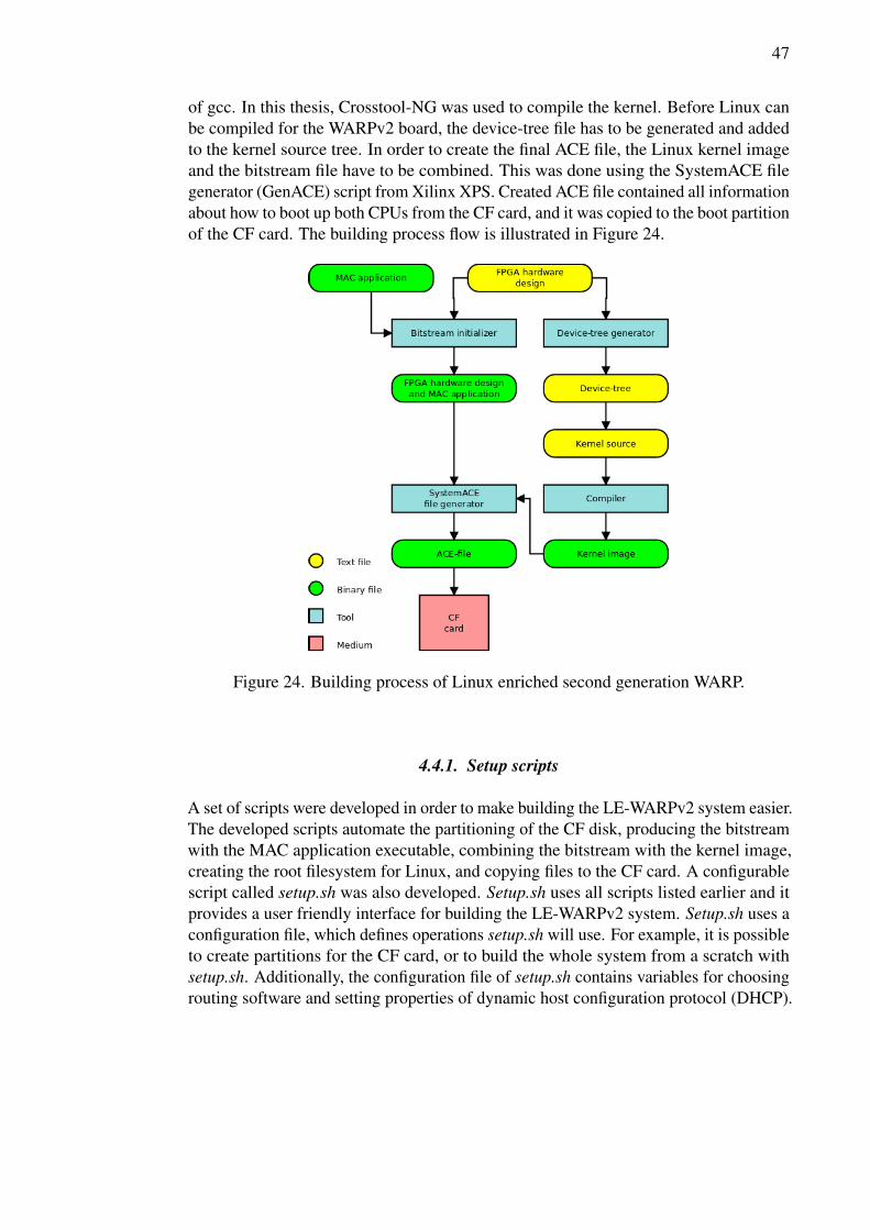
47
of gcc. In this thesis, Crosstool-NG was used to compile the kernel. Before Linux canbe compiled for the WARPv2 board, the device-tree file has to be generated and addedto the kernel source tree. In order to create the final ACE file, the Linux kernel imageand the bitstream file have to be combined. This was done using the SystemACE filegenerator (GenACE) script from Xilinx XPS. Created ACE file contained all informationabout how to boot up both CPUs from the CF card, and it was copied to the boot partitionof the CF card. The building process flow is illustrated in Figure 24.
Figure 24. Building process of Linux enriched second generation WARP.
4.4.1. Setup scripts
A set of scripts were developed in order to make building the LE-WARPv2 system easier.The developed scripts automate the partitioning of the CF disk, producing the bitstreamwith the MAC application executable, combining the bitstream with the kernel image,creating the root filesystem for Linux, and copying files to the CF card. A configurablescript called setup.sh was also developed. Setup.sh uses all scripts listed earlier and itprovides a user friendly interface for building the LE-WARPv2 system. Setup.sh uses aconfiguration file, which defines operations setup.sh will use. For example, it is possibleto create partitions for the CF card, or to build the whole system from a scratch withsetup.sh. Additionally, the configuration file of setup.sh contains variables for choosingrouting software and setting properties of dynamic host configuration protocol (DHCP).

48
4.5. Booting the system
The XPS embedded development kit (EDK) creates a bitstream file, which contains theFPGA hardware design and the application executable of the MAC side. The GenACEprogram from the Xilinx tool set produces an ACE file, which is the file format used bySystemACE. The ACE file consists of the bitstream and the compressed Linux kernelimage. The ACE file can be used to initialize and configure FPGA and memories witha valid program or data, and boot up processors. In practice, the ACE file consists ofa sequence of JTAG operations for each necessary tasks. SystemACE generates theseJTAG commands when it scans through the ACE file.
When the LE-WARPv2 board is booted, the SystemACE chip scans the ACE filestored in the boot sector of the CF disk. SystemACE then configures the FPGA, loads theMAC application to the boot memory of the MAC side and the bootloader applicationto the boot memory of Linux, sets entry points for applications, and starts applications.The linker script of the MAC application contains information about the memory regionwhere the MAC application will be loaded. The bootloader application starts whenSystemACE has loaded it to the memory. The task of the bootloader is to load thekernel image to the main memory and start it. The boot process of the LE-WARPv2 isrepresented in Figure 25.
Figure 25. Booting process of Linux enriched second generation WARP.
In this thesis, the bootloader provided by Xilinx was used. Another option forbootloading would have been U-boot. Although U-boot has richer features than theXilinx bootloader, it was decided to not use it. The decision was made because theXilinx bootloader provides needed features, it is simpler to set up, and the Xilinxbootloader is shipped with Xilinx EDK.
4.6. Debugging
Developed drivers were debugged using printed statements and the combination ofXMD and GDB. Printed statements were used to verify that the developed module was

49
loaded and initialized properly. XMD was used as a GDB server. GDB, which wasrunning on the host computer, was connected to the server. The combination of XMDand GDB was used to verify that the module actually works as planned; breakpointswere set and when a breakpoint was reached, the values of the variables were checkedin order to verify that they were as expected.

50
5. TESTING, VERIFICATION AND ANALYSIS
Testing is an important part of any implementation project. The purpose of testing is toverify that the implemented system works correctly.
5.1. Test cases
Several test cases were created to verify that the LE-WARPv2 system behaves asplanned. Test cases were divided into two sections: hardware tests and performancetests. The Hardware tests aimed to verify that the hardware of the LE-WARPv2 systemwas properly configured and the performance of hardware components was decent,whereas the purpose of the performance tests was to confirm that performance of thewhole system fulfilled requirements.
5.1.1. Hardware tests
Hardware controlled by Linux was tested extensively. Moreover, the modified hardwareof the MAC side was also tested. Used tests included:
• Memory test Main memory of Linux was tested with the application calledmemtester [58]. Memtester is a memory tester for stress testing the memorysubsystem. It can be used to find intermittent and non-determistic faults [59].
• Serial port test The serial port was connected to the MAC side in the FPGAhardware design. The purpose of the serial port test was to verify that serialport functionality is working correctly. The test consisted of prints added tothe MAC application and a serial terminal client ran on the host computer. TheWARPv2 board was connected to the host computer via a serial cable. The testwas passed, if prints showed up in the serial terminal client when the WARPboard was powered up.
• Ethernet test Ethernet was tested using ping [60] and iperf [61] programs. Basicfunctionality was tested with ping and advanced properties, such as throughput,were tested with iperf. The basic functionality test was passed, if the WARPv2board sent ping reply every time when the board was pinged. If packet lossoccurred, the test was considered as failed.
The purpose of iperf test was to verify that throughput of Ethernet was eligibleand it did not hang or crash in any case.
• Interprocessor connection test Communication between the processor coreswas tested using using warptool and warplogd userspace applications and theWarpnet device driver. Test data was delivered from Linux to the MAC side usingwarptool and this data was printed to the serial terminal on the MAC side. Thetest was passed, if printed data was the same than delivered. Communicationfrom the MAC side to Linux was tested with warplogd. Test data was flushed to

51
shared memory, where warplogd read and stored it to the log file. This test waspassed if data in the log file was the same than flushed data on the MAC side.
IP traffic communication was tested using the wireless Ethernet interface providedby the Warpnet device driver; a fixed Ethernet packet was sent via wirelessEthernet interface and the MAC application printed the content of the packet tothe serial terminal. The test was passed if the content of the packet was the samein the both ends.
• Wireless communication test This test required two WARPv2 boards. Radiosof boards were set to use the same frequency and channel. Linux was configuredto give IP addresses to boards from the same address space. Then the wirelessconnection was tested using the ping program. If the board which sent pingrequests got replies from the other board without packet loss, then the test waspassed. The test setup is illustrated in Figure 26.
5.1.2. Performance tests
Performance of the system was measured by several tests. Performance test casesconsisted of the network throughput test, a CPU stress test, and the size of memoryfootprint.
• Throughput test Throughput between two WARPv2 boards was measured usingboth the Linux enriched design and the OFDM reference design. The CSMAMAC application was used in measurement. The application was modified beforemeasurements, because it had a programming error which caused poor TCPthroughput performance with the OFDM reference design. In measurements,boards were connected with coaxial cables and HP 8496B 60 dB attenuator[62] instead of a wireless link. This was done in order to get more reliableand comparable results. Measured throughput values were compared. Thetest was considered as passed, if throughput values with the Linux enricheddesign were the same order of magnitude than values with the OFDM referencedesign. Measurement was done using the user datagram protocol (UDP) andTCP protocols with the quadrature phase shift keying (QPSK) modulation. Iperfprogram version 2.0.5 was used as measurement software. The test setup wassimilar as illustrated in Figure 26 except that the wireless connection was replacedwith coaxial cables and an attenuator.
• CPU stress test The purpose of the CPU stress test was to find out how wellthe Linux system behaves when the CPU is under a heavy load. A simple testapplication was written to generate a heavy load to the processor. A ping programwas used to indicate if the system is behaving correctly under a heavy load; thehost computer connected to the WARPv2 board via wire was pinging constantlythe WARPv2 board. The test was considered as passed, if the system did not crashor hang under a heavy CPU load, and the WARPv2 board replied ping requestswithout packet loss.

52
Figure 26. Test setup for wireless communication.
• Memory usage Memory usage was tested in the idle state of the system. A usedtest program was free [63]. The purpose of the test was to confirm that there isenough memory left for userspace applications.
5.2. Test results
Each test was executed multiple times to get more reliable results. According to thetest results, the developed system worked as planned. Hence, the system fulfilled itsrequirements. Results of test cases were following:
• Memory test The test was ran five times and it was passed every time. Figure 27shows the output of the test program.
• Serial port test When the WARPv2 board was powered up, prints showed up inthe serial terminal client on the host computer. Therefore, the test was passed.The test was repeated several times.
• Ethernet test The WARPv2 board replied ping requests sent by the host computerevery time without packet loss. Hence, the basic functionality test was passed.
• Interprocessor communication test Data delivered from Linux to the MAC sideby warptool stayed intact, so this test was passed. The MAC side was able towrite log data which was delivered to Linux by warplogd. Therefore, this part ofthe test was also passed.
• Wireless communication test The connection between WARPv2 boards wasformed successfully and there was zero lost packets when pinging. Thus, the testwas passed.

53
Figure 27. The output of the memory tester.
• Throughput test UDP test results are shown in Figures 28 and 29. According tothe test results, the throughput performance of the Linux enriched design whenusing UDP was similar to the OFDM reference design.
TCP results are shown in Table 7. The OFDM reference design had slightlybetter throughput performance than the Linux enriched design. Nonetheless, thethroughput performance of the Linux enriched design fulfilled requirements.
Table 7. Throughput comparison using TCPDesign Transfer (Mbytes) Bandwidth (Mbit/s)The OFDM reference design 62.6 5.24The Linux enriched design 48.7 4.09
• CPU stress test The system was responsive under a heavy CPU load. The testwas passed.
• Memory usage The measurement result of memory usage can be seen in Table 8.The memory usage test verified that the memory usage of the system itself waspredicted and there was enough memory left for applications.
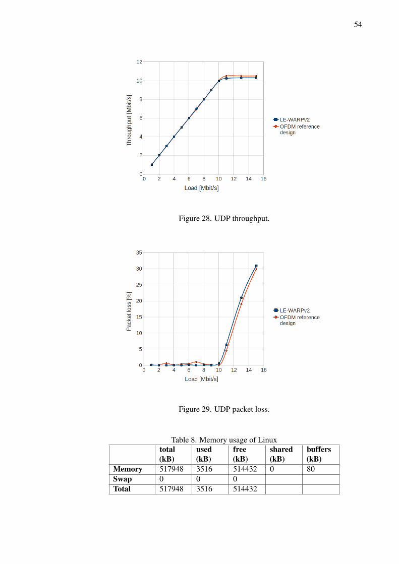
54
Figure 28. UDP throughput.
Figure 29. UDP packet loss.
Table 8. Memory usage of Linuxtotal(kB)
used(kB)
free(kB)
shared(kB)
buffers(kB)
Memory 517948 3516 514432 0 80Swap 0 0 0Total 517948 3516 514432

55
5.3. FPGA resource usage analysis
Used FPGA resources in the OFDM reference design and the Linux enriched designcan be seen in Table 9. According to this table, the Linux enriched design uses only 10percentage points more slices than the OFDM reference design.
Table 9. FPGA resources of the OFDM reference design 16.1 and the LE-WARPv2design
Resource Usage in theOFDM referencedesign
Usage in the Linuxenriched design
Occupied Slices 76% 86%4 input LUTs 62% 71%Bonded IOBs: 48% 65%BUFG/BUFGCTRLs 40% 46%FIFO16/RAMB16s 84% 97%DSP48s 98% 98%DCM_ADVs 25% 25%PPC405_ADVs 100% 100%EMACs 50% 50%BSCAN_VIRTEX4s 25% 25%JTAGPPCs 100% 100%IDELAYCTRLs 7% 23%
The Linux enriched design demands 86% of available slices of the FPGA. Therefore,the FPGA can be considered as heavily utilized. The Linux side of the design mightbe difficult to reduce without loosing features. However, there is a lot of room forimproving the MAC side design, since some functionalities, such as packet detector,have more than one implementation in the design. Moreover, the MAC side hascomponents which are not used in the design. Therefore, the free area of the FPGA canbe increased by removing unused and duplicate components from the design.
56
6. DISCUSSION
The baseline of this thesis was to port the Linux system for the second generation WARPplatform to provide a versatile and efficient platform for needs of advanced wirelessnetworks research, especially for the CRN trial environment. The goal was to provide asystem which is easily managed and can control all layers of the OSI model and canbe used as part of the trial environment. Furthermore, it was required that the systemshould achieve eligible performance, so it could be used to run measuring, monitoringand other applications needed in the researching, in addition to utilities, such as routingsoftware, which are essential in the network environment.
The system developed in this thesis consists of the Linux side and the MAC side. TheLinux side was designed to implement the Linux kernel with necessary applications andutilities in order to control the network functionalities of the system, whereas the MACside was designed to provide PHY and MAC functionalities with programmability. Thewhole system can be controlled via Linux as required. The MAC side control wasimplemented with Linux kernel drivers. These drivers provide mechanisms to exchangedata between the Linux side and the MAC side. Userspace applications were developedto use these mechanisms and to implement control functions. According to the testresults, the performance of the system achieved the requirements; the throughput ofthe developed system was similar to the OFDM reference design, which was used as astarting point of the developed system. Moreover, the CPU and the memory usage ofthe developed system were low, so there is decent amount of resources left for researchapplications. Therefore, it can be said that the goals of the thesis were fulfilled.
Comparing this implementation with the same type of existing concepts is challengingsince there are only a few designs that have similarities with the design implementedin this thesis. In [47], the authors present the first generation WARP with Linux.LE-WARPv2 is based on this work. Therefore, architectures of these designs do notdiffer much. For example, communication between the PowerPC cores is implementedusing mailboxes and shared memory and the root filesystem is on the CF card in bothdesigns. However, in [47] Ethernet is implemented using the Ethernet MAC IP coreprovided by Xilinx, whereas in LE-WARPv2 Ethernet is implemented by TEMAC. Inpractice, this means that LE-WARP design supports only 10 or 100 Mbit/s Ethernetconnections, whereas LE-WARPv2 supports also 1000 Mbit/s connection. Due todifferences in the hardware, it is not reasonable to compare the CPU or memory usagesof systems. Nonetheless, the throughput performance of systems is comparable, becausethe hardware implementing the wireless connection is the same in both design. In [47],the UDP throughput was 9 Mbit/s, while in the LE-WARPv2 design it was 10.3 Mbit/s.TCP throughput was not measured in [47]. The difference in the UDP throughput resultscan be explained by the newer PHY IP cores used in the LE-WARPv2 design and betterimplementation of the wireless interface kernel driver.
LE-WARPv2 extends the features of the WARPv2 board. It provides a feature-richplatform for advanced wireless networks researching without a need to manage a fullcomplexity of the platform; Linux offers interfaces for applications to use hardware ofthe WARPv2 board efficiently and it has wide variety of tools and utilities availablerequired in the advanced wireless networks research. Furthermore, Linux makes possi-ble to control MAC and PHY layers of the WARPv2 board. LE-WARPv2 board canbe connected together in order to form a network. This makes possible to form a trial

57
environment for advanced wireless networks, such as CRN, researching. In other words,LE-WARPv2 enables the researchers of advanced wireless networks to set up a wirelesstest network to test and verify complex theoretical algorithms at different layers of OSImodel and find out the practical limitations of theoretical results.
As concrete proof of the versatility and capability of LE-WARPv2 presented inthis thesis, the implementation was extended with a time division multiple access(TDMA) based MAC application and a graphical user interface (GUI) and the CRN wascreated in order to demonstrate an automatic offloading algorithm designed at CWC.This demonstration was introduced in Workshop on Cognitive Radio and SoftwareDefined Radio: Policy and Regulations organised jointly by electronic communicationcommittee (ECC)/European cooperation in science and technology - techno-economicregulatory framework for radio spectrum access for cognitive radio/software definedradio (COST-TERRA) which was held in Mainz, Germany at May 2012 [64].
In order to make a maintaining of LE-WARPv2 easier, the Linux kernel, Buildrootand Busybox could be updated to newer versions. Newer kernels include several patcheswhich now have to be added manually. Buildroot and Busybox have been developedactively and newer versions of them provide, in addition to bug fixes, better support forthird-party applications. Therefore, it would be easier to include and maintain softwarewritten for Linux on WARPv2.
Real-time features could be added to the Linux kernel. There are real-time patchesavailable for the current kernel and for newer kernels in [65]. Real-time features maybe needed in certain research efforts like in high performance IP packet processingresearch.
Kernel drivers for interprocessor communication could be improved. The Warpnetdriver should have a mechanism to store network packets temporarily when it can notprocess them; now the driver will drop packets if it is busy. Adding buffers does notsolve this problem if packets are coming faster than the driver can handle them. Ifpacket dropping is not an option, the MAC side should reject incoming packets untilthe shared memory is available again and the Linux side should store these packets andtry to send them later. When traffic from the Linux side to the MAC side is too fast, theMAC side should not free a shared memory slot. Instead, it should store packets whichit cannot send immediately and try to send them later. This method would quaranteethat packets will not be dropped in any cases.
The Warptool driver cannot deliver more than 24 bit data from the Linux side to theMAC side. This may become a bottleneck if there is a need to deliver more data to theMAC side. The Warptool driver could be improved by allocating one or more slotsfrom the shared memory for data delivering from the Linux side to the MAC side. Nowall slots of the shared memory are allocated for data from the MAC side to the Linuxside and data from the Linux side to the MAC side is delivered via mailbox without theshared memory.

58
7. SUMMARY
Researchers of advanced wireless networks need a platform, where they can test andverify complex theoretical algorithms at different layers of the OSI model and find outthe practical limitations of theoretical results. However, setting up a platform or anenvironment for advanced wireless networks, such as CRNs, might be time consumingand it may demand special skills and a heavy workload. The goal of this thesis was toport the Linux system for the second generation WARP board to provide a versatile andefficient platform for needs of advanced wireless networks researching. The developedsystem is easily managed and capable of controlling all layers of the OSI model and itis used as part of the trial environment for CRNs and other types of advanced wirelessnetworks.
In this thesis, the Linux system was ported for the second generation WARP board.The Linux system was combined with the radio communication system provided byRice University, USA. The FPGA hardware design was created for this combination andneeded software of the system was defined and implemented. The developed systemconsisted of the Linux side, which took care of a network layer of the OSI model andlayers above it, and the MAC side, that implemented the PHY and MAC layers. Bothsides used a dedicated processor core of the FPGA. Interprocessor communicationbetween Linux and MAC sides was implemented to enable Linux to control the wholesystem. Interprocessor communication was implemented using mailboxes and sharedmemory between processor cores. Two Linux kernel drivers were written to useinterprocessor communication hardware. Several scripts were written to simplify thesetup process of the LE-WARPv2 system.
Several test cases were created and the developed system was tested, verified andanalyzed to confirm that the implementation is valid and consistent. Test cases weredivided into two parts: hardware tests and performance test. Hardware tests verifiedthat the FPGA hardware design of the system was workable and fulfilled the require-ments. Performance tests confirmed that the performance of the system was sufficient.According to test results, the developed LE-WARPv2 system enabled the controlling ofall layers of the OSI model without a need to manage its full complexity. Moreover,the LE-WARPv2 was able to form a trial environment for advanced wireless networksresearch as required.
59
8. REFERENCES
[1] Linus Benedict Torvalds (5 October 1991). "Free minix-like kernel sources for 386-AT", (accessed 27.6.2012). URL: http://groups.google.com/group/comp.os.minix/msg/2194d253268b0a1b?pli=1.
[2] Abbott D. (2003) Linux for embedded and real-time applications. Embeddedtechnology, Newnes, 255 p.
[3] git.kernel.org – linux/kernel/git/stable/linux-stable.git/blob – readme, (ac-cessed 27.6.2012). URL: http://git.kernel.org/?p=linux/kernel/git/stable/linux-stable.git;a=blob;f=README;h=9beaed0ed620b31495a89c79fd12f7f926f7d902;hb=28a33cbc24e4256c143dce96c7d93bf423229f92.
[4] IEEE Standard for Information Technology- Portable Operating System Interface(POSIX) Base Specifications, Issue 7 (2008). IEEE Std 1003.1-2008 (Revision ofIEEE Std 1003.1-2004) , pp. c1 –3826.
[5] Free Software Foundation, (accessed 19.7.2012) GNU General Public Licensev2.0. URL: http://www.gnu.org/licenses/gpl-2.0.html.
[6] What is linux: An overview of the linux operating system, (accessed 27.6.2012).URL: https://www.linux.com.
[7] The Linux Kernel Archives, (accessed 4.7.2012). URL: http://kernel.org.
[8] Rubini A. & Corbet J. (2001) Linux device drivers. O’Reilly Series,O’Reilly & Associates. URL: http://books.google.fi/books?id=53-wm0d-BFwC.
[9] Rusling D.A. (1999) The Linux Kernel (version 0.8-3). URL: http://www.tldp.org/LDP/tlk/.
[10] NixCraft, (accessed 16.7.2012) Understanding UNIX / LinuxFile System. URL: http://www.cyberciti.biz/tips/understanding-unixlinux-file-system-part-i.html.
[11] Jones T., (accessed 16.7.2012) Anatomy of the Linux file system. URL: http://www.ibm.com/developerworks/linux/library/l-linuxboot/.
[12] Hallinan C. (2006) Embedded Linux Primer: A Practical Real-World Approach.Prentice Hall PTR, Upper Saddle River, NJ, USA, 542 p.
[13] The Resource Center for Free Operating System, (accessed 12.7.2012) Introduc-tion to Linux kernel modules. URL: http://freeos.com.
[14] Yaghmour K., Masters J., Ben-Yossef G. & Gerum P. (2008) Building embeddedLinux systems. O’Reilly Series, O’Reilly.
[15] On-line Linux and Open Source Technology Books and How To Guides, (accessed5.7.2012). URL: http://linuxtopia.org.

60
[16] Jones T., (accessed 6.9.2012) Inside the Linux boot process. URL: http://ibm.com/developerworks/linux/library/l-linux-filesystem/.
[17] Fusco J. (2007) The Linux Programmer’s Toolbox. Prentice Hall Open SourceSoftware Development Series, Prentice Hall. URL: http://books.google.fi/books?id=5fgn7Tg4Lt8C.
[18] Software Debugging Techniques for PowerPC 440 Processor Embedded Platforms(accessed 24.9.2012). URL: www.xilinx.com/.
[19] GDB: The GNU Project Debugger, (accessed 12.7.2012). URL: http://sources.redhat.com/gdb/.
[20] Asokan V., Designing Multiprocessor Systems in Platform Studio (ac-cessed 24.9.2012). URL: http://www.xilinx.com/cn/support/documentation/white_papers/wp262.pdf.
[21] Embedded System Tools Reference Manual (accessed 24.9.2012). URL:www.xilinx.com/support/documentation/sw_manuals/edk10_est_rm.pdf.
[22] Linux Operating System Software Debugging Techniques with Xilinx EmbeddedDevelopment Platforms (accessed 24.9.2012). URL: www.xilinx.com/.
[23] uClibc, (accessed 28.8.2012). URL: http://uclibc.org/about.html.
[24] diet libc – a libc optimized for small size, (accessed 28.8.2012). URL: http://www.fefe.de/dietlibc/.
[25] Parkin T., (accessed 28.8.2012) Tools and distributions for embedded Linuxdevelopment. URL: http://lwn.net/Articles/384713/.
[26] MontaVista embedded Linux software and development tool for intelligence deviceand embedded systems, (accessed 28.8.2012). URL: http://www.mvista.com/.
[27] Wind River, (accessed 28.8.2012). URL: http://www.windriver.com/.
[28] Buildroot: making Embedded Linux easy, (accessed 20.7.2012). URL: http://buildroot.uclibc.org.
[29] OpenEmbedded, (accessed 28.8.2012). URL: http://www.openembedded.org/wiki/Main_Page.
[30] Scratchbox, (accessed 28.8.2012). URL: http://www.scratchbox.org/.
[31] Emdebian – The Universal Embedded Operating System, (accessed 28.8.2012).URL: http://www.emdebian.org/.
[32] Gentoo Linux Projects – Embedded Gentoo, (accessed 28.8.2012). URL: http://www.gentoo.org/proj/en/base/embedded/.
[33] OpenWRT, (accessed 28.8.2012). URL: https://openwrt.org/.
61
[34] Tomato Firmware, (accessed 28.8.2012). URL: http://www.polarcloud.com/tomato/.
[35] Android, (accessed 28.8.2012). URL: http://www.android.com/.
[36] Mer Project, (accessed 28.8.2012). URL: http://merproject.org/.
[37] BusyBox: The Swiss Army Knife of Embedded Linux, (accessed 20.7.2012).URL: http://www.busybox.net.
[38] Penguinppc.org – the home of the linux/ppc port, (accessed 17.7.2012). URL:http://penguinppc.org.
[39] Likely G. & Boyer J. (2008) A symphony of flavours: Using the device tree todescribe embedded hardware. In: Proceedings of the Linux Symposium, vol. 2,Ottawa, Ontario, Canada, vol. 2, p. 27 – 37.
[40] Gibson D. & Herrenschmidt B. (2006) Device trees everywhere. Tech. rep., IBMLinux Technology Center.
[41] Herrenschmidt B., Bruce B. & MontaVista Software Inc. (2005, 2006)Booting the Linux/ppc kernel without Open Firmware, (accessed 23.7.2012).URL: http://git.xilinx.com/?p=linux-xlnx.git;a=blob;f=Documentation/devicetree/booting-without-of.txt;h=7c1329de0596a34ce81d60f214d46a43933f05c0;hb=HEAD.
[42] Virtex-II Pro and Virtex-II Pro X Platform FPGAs: Complete DataSheet (accessed 24.9.2012). URL: http://www.xilinx.com/support/documentation/data_sheets/ds083.pdf.
[43] Virtex-4 Family Overview (accessed 24.9.2012). URL: http://www.xilinx.com/support/documentation/data_sheets/ds112.pdf.
[44] Xilinx GIT Linux repository, (accessed 23.7.2012). URL: http://git.xilinx.com/.
[45] Xilinx open source wiki, (accessed 23.7.2012). URL: http://wiki.xilinx.com/.
[46] Tuomivaara H., Raustia M. & Jokinen M. (2009) Demonstration of distributedTDMA MAC protocol implementation with OLSR on linux enriched WARP. In:WiNTECH’09 - Proc. 4th ACM International Workshop on Wireless NetworkTestbeds, Experimental Evaluation and Characterization, pp. 85–86. URL: www.scopus.com.
[47] Jokinen M. & Tuomivaara H. (2011) LE-WARP: Linux enriched design for wire-less open-access research platform. In: Proceedings of the 4th International Con-ference on Cognitive Radio and Advanced Spectrum Management, CogART ’11,ACM, New York, NY, USA, pp. 16:1–16:5. URL: http://doi.acm.org/10.1145/2093256.2093272.

62
[48] Greco A., Milcher T., Kolar V., Mähönen P. & Petrova M. (2009) CSMA interac-tion detection and capacity estimation in cognitive radio networks. In: Proceed-ings of the tenth ACM international symposium on Mobile ad hoc networkingand computing, MobiHoc ’09, ACM, New York, NY, USA, pp. 321–322. URL:http://doi.acm.org/10.1145/1530748.1530794.
[49] Chen Z., Zhang C., Lin F., Yu J., Li X., Song Y., Ranganathan R., Guo N. & QiuR.C. (2012) Towards a large-scale cognitive radio network: Testbed, intensivecomputing, frequency agility and security. In: 2012 International Conference onComputing, Networking and Communications, ICNC’12, pp. 556–562. URL:www.scopus.com.
[50] Rice University WARP Project, (accessed 3.1.2012). URL: http://warp.rice.edu.
[51] Murphy P., Sabharwal A. & Aazhang B. (2006) Design of WARP: A FlexibleWireless Open-Access Research Platform. In: Proceedings of EUSIPCO, pp. 1–4.
[52] LogiCORE IP Multi-Port Memory Controller (MPMC) (v6.03.a) (ac-cessed 24.9.2012). URL: http://www.xilinx.com/support/documentation/ip_documentation/mpmc.pdf.
[53] 88E1111 Product Brief Integrated 10/100/1000 Ultra Gigabit Ethernet Transceiver,(accessed 27.7.2012). URL: http://www.alldatasheet.com/datasheet-pdf/pdf/316947/MARVELL/88E1111-XX-BAB-C000.html.
[54] LogiCORE IP XPS LL TEMAC (v2.03a) (accessed 24.9.2012). URL:http://www.xilinx.com/support/documentation/ip_documentation/xps_ll_temac.pdf.
[55] LogiCORE IP XPS LL FIFO (v1.02a) (accessed 24.9.2012). URL:http://www.xilinx.com/support/documentation/ip_documentation/xps_ll_fifo.pdf.
[56] MAX2829/MAX2829, (accessed 28.6.2012). URL: http://www.xilinx.com/support/documentation/ip_documentation/mpmc.pdf.
[57] OS and Libraries Document Collection (accessed 24.9.2012). URL:www.xilinx.com/support/documentation/sw_manuals/xilinx12_4/oslib_rm.pdf.
[58] Pyropus Technology, (accessed 24.9.2012) Memtester. URL: http://pyropus.ca/software/memtester/.
[59] memtester(8) – Linux man page, (accessed 24.9.2012). URL: http://linux.die.net/man/8/memtester.
[60] ping(8) – Linux man page, (accessed 24.9.2012). URL: http://linux.die.net/man/8/ping.

63
[61] iperf, (accessed 24.9.2012). URL: http://iperf.fr/.
[62] Agilent 8494/95/96A/B Attenuators, (accessed 24.9.2012). URL:www.home.agilent.com/agilent/redirector.jspx?action=ref&cname=AGILENT_EDITORIAL&ckey=1000001712-1%3Aepsg%3Aman&lc=fin&cc=FI&nfr=-536900768.536879122.00.
[63] free(1) – Linux man page, (accessed 24.9.2012). URL: http://linux.die.net/man/1/free.
[64] Workshop on cognitive radio and software defined radio, (accessed22.8.2012). URL: http://cept.org/ecc/groups/ecc/page/workshop-on-cogitive-radio.
[65] Index of /pub/linux/kernel/projects/rt, (accessed 23.8.2012). URL: http://kernel.org/pub/linux/kernel/projects/rt/.

64
9. APPENDICES
Appendix 1 Linux kernel configurations

65
Appendix 1 Linux kernel configuration
Category FeatureProcessor type AMCC 40xGeneral setup Prompt for development and/or incomplete code/driversGeneral setup (12) Kernel log buffer size (16 => 64KB, 17 => 128KB)General setup Create deprecated sysfs filesGeneral setup Namespaces supportGeneral setup Optimize for sizeGeneral setup Configure standard kernel features (for small systems)General setup Disable heap randomizationGeneral setup Enable futex supportGeneral setup Enable eventpoll supportGeneral setup Enable signalfd() system callGeneral setup Enable timerfd() system callGeneral setup Enable eventfd() system callGeneral setup Enable AIO supportGeneral setup Choose SLAB allocator (SLOB (Simple Allocator))Enable the block layer IO Schedulers: Deadline I/O schedulerPlatform support Generic Xilinx Virtex boardKernel options Timer frequency (250 HZ)Kernel options Preemption Model (No Forced Preemption (Server))Kernel options Kernel support for ELF binariesKernel options Math emulationKernel options Memory model (Flat Memory)Kernel options (11) Maximum zone orderKernel options Support for device tree in /procKernel options Default bootloader kernel argumentsNetworking support->Networking options
Packet socket
Networking support->Networking options
Packet socket: mmapped IO
Networking support->Networking options
Unix domain sockets
Networking support->Networking options
TCP/IP networking
Networking support->Networking options
IP: multicasting
Networking support->Networking options
IP: advanced router
Networking support->Networking options
Choose IP: FIB lookup algorithm (FIB_HASH)
Networking support->Networking options
IP: kernel level autoconfiguration

66
Networking support->Networking options
IP: multicast routing
Device Drivers Generic Driver Options: Select only drivers that don’t needcompile-time external
Device Drivers Block devices: Loopback device supportDevice Drivers Block devices: Xilinx SystemACE supportDevice Drivers Network device support: Ethernet (1000Mbit): Xilinx LL-
TEMAC 10/100/1000 Ethernet MAC driver Xilinx LL-TEMAC PHY Support (MARVELL 88E1111 using GMII)
Device Drivers Network device support: WARP board MAC side driverDevice Drivers Character devices: Virtual terminalDevice Drivers Character devices: Enable character translations in consoleDevice Drivers Character devices: Support for console on virtual terminalDevice Drivers Character devices: Unix98 PTY supportDevice Drivers Character devices: Xilinx HWICAP SupportDevice Drivers Character devices: WARP board configuration driverDevice Drivers Malibu interface on WARP boardDevice Drivers Generic Driver Options: Prevent firmware from being builtFile systems Second extended fs supportFile systems DOS/FAT/NT Filesystems: MSDOS fs supportFile systems DOS/FAT/NT Filesystems: VFAT (Windows-95) fs supportFile systems DOS/FAT/NT Filesystems: (437) Default codepage for FATFile systems DOS/FAT/NT Filesystems: (iso8859-1) Default iocharset
for FATFile systems Pseudo filesystems: /proc file system supportFile systems Pseudo filesystems: /proc/kcore supportFile systems Pseudo filesystems: Sysctl support (/proc/sys)File systems Pseudo filesystems: Enable /proc page monitoringFile systems Pseudo filesystems: sysfs file system supportFile systems Native language support: (iso8859-1) Default NLS OptionFile systems Native language support: Codepage 437 (United States,
Canada)File systems Native language support: NLS ISO 8859-1 (Latin 1; Western
European Languages)Library routines CRC32 functionsKernel hacking Enable __deprecated logicKernel hacking Enable __must_check logicKernel hacking (1024) Warn for stack frames larger than (needs gcc 4.4)Kernel hacking Sysctl checks