lecture v - brookhaven national laboratory
TRANSCRIPT

SuperconductingMagnet Division
Ramesh Gupta, BNLUSPAS Course on Superconducting Accelerator Magnets, June 23-27, 2003 Slide No. 1 of Lecture V
Magnetic Design Yoke Optimization
Ramesh GuptaSuperconducting Magnet Division Brookhaven National Laboratory
Lecture V
US Particle Accelerator SchoolUniversity of California – Santa Barbara
June 23-27, 2003

SuperconductingMagnet Division
Ramesh Gupta, BNLUSPAS Course on Superconducting Accelerator Magnets, June 23-27, 2003 Slide No. 2 of Lecture V
Use of Iron Yoke in theConductor Dominated Magnets (1)
Why should we use yoke in the conductor dominated magnets?Specially in high field magnets, where most of the field isprovided by coil. Disadvantage of yoke is that it increases thecoldmass. That means it increases the size, weight and the volumeto be cooled down.
Reason No. 1:• For a variety of reasons, the magnetic field, at a certain distanceaway from magnet aperture, should become sufficiently small.• In almost all cases, and in virtually all accelerator magnets built sofar, the iron yoke over the coil has been found to be the most costeffective method of providing the required magnetic shielding.

SuperconductingMagnet Division
Ramesh Gupta, BNLUSPAS Course on Superconducting Accelerator Magnets, June 23-27, 2003 Slide No. 3 of Lecture V
Shielding
The shielding against the fringe field can be eitherprovided by the iron yoke or by the additional outercoils having an opposite polarity of the main coils.Home Assignment on the Shielding by Coils:• A thin cosine theta dipole coil is placed at a radius of 10 cm. This coil generates a centralfield of 0.5 T. Compute the relative strength of an additional thin coil at a radius of 20 cmthat is placed to cancel the fringe field far away from coil regions. Also compute the changein central field caused by this additional coil? Compute the change in central field, if insteadof additional coil, a thick iron yoke is placed at a radius of 20 cm to provide the requiredshielding. What happens, if the yoke shielding is brought right at 10 cm. In thesecalculations, ignore saturation of the iron yoke and assume that it has infinite permeability.
• Do the similar computations for quadrupole coils generating a field gradient of 5 T/mm.
• Generally speaking what would you use in your design for providing shielding and why? Inwhich case you would prefer the additional coil and in which the yoke?
Yet another possibility: Superconducting shield -- again, extra conductor.

SuperconductingMagnet Division
Ramesh Gupta, BNLUSPAS Course on Superconducting Accelerator Magnets, June 23-27, 2003 Slide No. 4 of Lecture V
Use of Iron Yoke in theConductor Dominated Magnets (2)
Why should we use yoke in the conductor dominated magnets?Reason No. 2:• The magnetized iron gives an additional contribution to the fieldgenerated by coils.• However, the gain does not come without any pain, particularly aswe get more and more ambitious (higher contribution, higher field).The iron starts saturating at high field. That makes field contributionnon-linear and field errors in the magnet (harmonics) depend on thecentral field.• The trick is to develop techniques to benefit from the gain whileminimizing the pain.•The purpose of this course is to make you familiar with thosetechniques by presenting the state-of-art.

SuperconductingMagnet Division
Ramesh Gupta, BNLUSPAS Course on Superconducting Accelerator Magnets, June 23-27, 2003 Slide No. 5 of Lecture V
BH Table Used in Calculations

SuperconductingMagnet Division
Ramesh Gupta, BNLUSPAS Course on Superconducting Accelerator Magnets, June 23-27, 2003 Slide No. 6 of Lecture V
Iron Yoke in RHIC Dipole
Yoke can contain field lines at low fields (~0.7 T, ~1 kA).No Fringe field outside.
Yoke can not contain field lines at high fields (~4.5 T, ~7 kA).Significant fringe field outside.

SuperconductingMagnet Division
Ramesh Gupta, BNLUSPAS Course on Superconducting Accelerator Magnets, June 23-27, 2003 Slide No. 7 of Lecture V
Saturation in RHIC Arc Dipole
In RHIC dipole, iron is closerto coil and contributes ~ 50%of the coil field:
3.45 T (Total) ~ 2.3 T (Coil) + 1.15 (Iron)
Initial design had bad saturation,as conventionally expected fromthe large saturation of the ironyoke. This course will teach youtechniques on how to reduce thecurrent-dependence of fieldharmonics.
Current Design
First Design
First Design
SuperconductingMagnet Division
Ramesh Gupta, BNLUSPAS Course on Superconducting Accelerator Magnets, June 23-27, 2003 Slide No. 8 of Lecture V
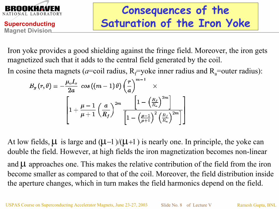
Consequences of theSaturation of the Iron Yoke
Iron yoke provides a good shielding against the fringe field. Moreover, the iron getsmagnetized such that it adds to the central field generated by the coil.In cosine theta magnets (a=coil radius, Rf=yoke inner radius and Ra=outer radius):
At low fields, µ is large and (µ−1)/(µ+1) is nearly one. In principle, the yoke candouble the field. However, at high fields the iron magnetization becomes non-linearand µ approaches one. This makes the relative contribution of the field from the ironbecome smaller as compared to that of the coil. Moreover, the field distribution insidethe aperture changes, which in turn makes the field harmonics depend on the field.

SuperconductingMagnet Division
Ramesh Gupta, BNLUSPAS Course on Superconducting Accelerator Magnets, June 23-27, 2003 Slide No. 9 of Lecture V
COS(mθ) Coil in Iron Shell
Rf: Iron inner radiusRa: Iron outer radiusa : Coil Radius
Note: µ is assumed to be constant in the entire iron yoke.

SuperconductingMagnet Division
Ramesh Gupta, BNLUSPAS Course on Superconducting Accelerator Magnets, June 23-27, 2003 Slide No. 10 of Lecture V
Field Enhancement forCOS(mθ) Coil in Iron Shell

SuperconductingMagnet Division
Ramesh Gupta, BNLUSPAS Course on Superconducting Accelerator Magnets, June 23-27, 2003 Slide No. 11 of Lecture V
Understanding The Iron Saturation (1)

SuperconductingMagnet Division
Ramesh Gupta, BNLUSPAS Course on Superconducting Accelerator Magnets, June 23-27, 2003 Slide No. 12 of Lecture V
Field and Saturation Parameters inRHIC Dipole with Circular Iron Yoke
Bmod (T)
(µ-1)/(µ+1)
Note the differencesbetween the pole and yoke.

SuperconductingMagnet Division
Ramesh Gupta, BNLUSPAS Course on Superconducting Accelerator Magnets, June 23-27, 2003 Slide No. 13 of Lecture V
Understanding The Iron Saturation (2)

SuperconductingMagnet Division
Ramesh Gupta, BNLUSPAS Course on Superconducting Accelerator Magnets, June 23-27, 2003 Slide No. 14 of Lecture V
Understanding The Iron Saturation (3)
Firs
t ord
er o
ptim
izat
ion:
For
ce a
sim
ilar
yoke
satu
ratio
n be
twee
n m
idpl
ane
and
pole

SuperconductingMagnet Division
Ramesh Gupta, BNLUSPAS Course on Superconducting Accelerator Magnets, June 23-27, 2003 Slide No. 15 of Lecture V
Method of Image Current to Understand andMinimize the Saturation-induced Harmonics
The contribution of a circular iron yoke with constant permeability (µ) can be described with the help ofimage currents. Note that in this case there will be only a radial component of the field at yoke innersurface. The field of a line current (I) at a radius “a” inside a circular iron cavity of radius Rf is given by:
The image current will be at the same angular location, however, themagnitude and the radial location are given by:

SuperconductingMagnet Division
Ramesh Gupta, BNLUSPAS Course on Superconducting Accelerator Magnets, June 23-27, 2003 Slide No. 16 of Lecture V
Development of the proposed approach forminimizing saturation induced harmonicswith the help of image current method
The image current “I” of a linecurrent at a radius “a” will be atthe same angular location,however, the magnitude and theradial location are given by:
> The block may be described by a series of line currents and the image blockby a series of image currents. The image block will produce a field (andharmonics) that is similar in shape as the main field, if the µ of the iron isconstant.
> In a real magnet with saturating, non-linear iron, it seems intuitively likely thatthe change in field shape (and harmonics) can be minimized by minimizing thevariation in µ and the quantitative deviation can be measured by (µ-1)/(µ+1).

SuperconductingMagnet Division
Ramesh Gupta, BNLUSPAS Course on Superconducting Accelerator Magnets, June 23-27, 2003 Slide No. 17 of Lecture V
A Conceptual Model for Understanding andMinimizing the Saturation-induced Harmonics
The contribution of a circular iron yoke with infinite permeability can be described with thehelp of image currents. A series of image currents (second term in the following expression)will retain the original angular distribution and the magnitude of them will be proportional tooriginal current, if the mu is constant in the iron (uniform magnetization across the iron).In that case only the primary component depends on the magnetization and no other harmonicswill change. Moreover, the change in primary component is related to (µ−1)/(µ+1).
The above theory does not work if the magnetization is not uniform. However, even in thatcase one can still develop a conceptual understanding and minimize the saturation-inducedharmonics by using the following hypothesis. Describe coil with a series of line current andassume that the image current is still at the same angular location but the magnitude isrelated to the average mu in the vicinity of the angular location where the line currents are.
The variation in saturation induced harmonics can be minimized, if thevariation in iron magnetization, as measured by (µ−1)/(µ+1), is minimized.

SuperconductingMagnet Division
Ramesh Gupta, BNLUSPAS Course on Superconducting Accelerator Magnets, June 23-27, 2003 Slide No. 18 of Lecture V
Significant Difference WithThe Conventional Method
In order to achieve a more uniform magnetization (iron saturation), one can force the field linesin the region where the iron was magnetized less. This will increase the overall magnetizationin the iron, but the attempt should be to force a more uniform magnetization, particularly in theiron region that is closer to aperture.
The conventional method called for not allowing the iron to saturate (too much magnetized).Minimizing non-linear iron means minimizing the saturation induced harmonics. This meantkeeping the iron away from the coil as that is a high field region. However, that also meantreducing the contribution of the iron to the total field as the iron near the aperture (coil)contributes more. In brief, the old method relied on reducing the region of iron that saturates.
The major difference between the method used in RHIC magnets, as compared to the earlierdesigns, with which major accelerator magnets have been built, that here the attempt was toincrease (forced) the saturation (to make it uniform) and before the attempt was to decrease it.
The close-in iron for obtaining higher field need not compromise the field quality as long as theiron saturation can be kept uniform, particularly in the iron region that is closer to aperture.

SuperconductingMagnet Division
Ramesh Gupta, BNLUSPAS Course on Superconducting Accelerator Magnets, June 23-27, 2003 Slide No. 19 of Lecture V
Saturation in RHIC Arc Dipole
In RHIC dipole, iron is closer tocoil and contributes ~ 50% ofthe coil field:
3.45 T (Total) ~ 2.3 T (Coil)+ 1.15 (Iron)
Initial design had bad saturation,(as expected from conventional wisdom),but a number of developments made thesaturation induced harmonics nearly zero!
Only full length magnets are shown.Design current is ~ 5 kA (~3.5 T).
Current Design
First Design
First Design

SuperconductingMagnet Division
Ramesh Gupta, BNLUSPAS Course on Superconducting Accelerator Magnets, June 23-27, 2003 Slide No. 20 of Lecture V
Saturation Control in RHIC DipolesVariation in |B| in Iron Yoke
• Compare azimuthal variation in |B| with and without saturation control holes.Holes, etc. increase saturation in relatively lower field regions; a moreuniform iron magnetization reduces the saturation induced harmonics.
• Old approach: reduce saturating iron with elliptical aperture, etc.• New approach: increase saturating iron with holes, etc. at appropriate places.
With out holesWith holes
SuperconductingMagnet Division
Ramesh Gupta, BNLUSPAS Course on Superconducting Accelerator Magnets, June 23-27, 2003 Slide No. 21 of Lecture V
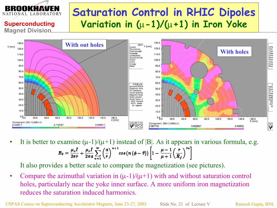
Saturation Control in RHIC DipolesVariation in (µ-1)/(µ+1) in Iron Yoke
• It is better to examine (µ-1)/(µ+1) instead of |B|. As it appears in various formula, e.g.
It also provides a better scale to compare the magnetization (see pictures).• Compare the azimuthal variation in (µ-1)/(µ+1) with and without saturation control
holes, particularly near the yoke inner surface. A more uniform iron magnetizationreduces the saturation induced harmonics.
With out holesWith holes

SuperconductingMagnet Division
Ramesh Gupta, BNLUSPAS Course on Superconducting Accelerator Magnets, June 23-27, 2003 Slide No. 22 of Lecture V
Current Dependence Beyond Design Field
• In all known major accelerator magnets (superconducting and iron dominated), the harmonics fallrapidly beyond the maximum design field. They are relatively flat in this design approach . Pleasenote the difference in scale (50 units in previous slides in b2 plots). It (a) shows a major impact ofthis design approach on field quality and (b) may have relevance to RHIC upgrade as most magnetsin RHIC have ~30% quench margin over the maximum design field.
-12
-10
-8
-6
-4
-2
0
2
0 0.5 1 1.5 2 2.5 3 3.5 4 4.5Bo (Tesla)
b2, b
4, b
6 (@
25m
m)
b2
b4
b6
b2
Current Dependence in RHIC Dipole DRG107 (DC Loop, Up Ramp)
Max. Design Field(~3.5 T, ~5kA)
Injection Field(~0.4 T, ~0.6 kA)

SuperconductingMagnet Division
Ramesh Gupta, BNLUSPAS Course on Superconducting Accelerator Magnets, June 23-27, 2003 Slide No. 23 of Lecture V
Influence of Lorentz Forceson Field Harmonics
Current
A typical Sextupole current dependencedue to Lorentz forces (schematic)
Low force/friction(practically no effect)
Radial motion
b2
Azimuthal motion
Coil makes contact to collar(maximum radial motion)
A small radial gap in magnets (50-100 micron), could bepresent due to tolerances in collar o.d. and yoke i.d. In
SSC that means ~-1 unit of sextupole. Such errors can beaccommodated in a flexible design - key material,etc.
The measured current dependence in field harmonics is a combination ofsaturation-induced harmonics, and the Lorentz force-induced harmonics.
Assignment: Make a similar sketch for b4 (decapole).

SuperconductingMagnet Division
Ramesh Gupta, BNLUSPAS Course on Superconducting Accelerator Magnets, June 23-27, 2003 Slide No. 24 of Lecture V
Measured Current Dependence in SextupoleHarmonic in Various Full-length SSC Magnets
Near zero current dependence in b2 variation in firstdesign itself in BNL built SSC 50 mm long magnets.
Specifications was 0.8 unit.
A much larger value in earlier SSC 40 mm design.b2 change from yoke magnetization & Lorentz forces. Major progress in reducing the
saturation-induced harmonics.
Cross section of SSC 50 mm DipoleYoke optimized for low saturation
Measurement of b2 current dependence in group of SSC magnets
-1.6
-1.2
-0.8
-0.4
0
0.4
0.8
1.2
1.6
2 3 4 5 6 7 8
Current (kA)
b2 (1
0 m
m),
US
conv
entio
n
dss020dss010dsa207dca207ds0202dsa311dc0201KEK501
SSC 50 mm (BNL-built)SSC Specification
SSC Specification
KEK (Fe Key)
Lorentz forces
Various SSC 40 and 50 mm dipoles
Non-magnetic key to force uniform saturationCould also have been used to adjust current
dependence after design, as in RHIC magnets.

SuperconductingMagnet Division
Ramesh Gupta, BNLUSPAS Course on Superconducting Accelerator Magnets, June 23-27, 2003 Slide No. 25 of Lecture V
Yoke Cross-section Optimization
To do detailed magnetic design, you must use one ofseveral available computer codes.
Some popular codes that are currently being used fordesigning accelerator magnets:
• POISSON, etc. (Developed in labs, public domain)• OPERA, ANSYS, etc. (Commercial)• ROXIE (Developed in labs, commercial & requires licensing)
In addition, various labs have written in-house computer codes tofulfill their special requirements. For example, all RHIC coils, for avariety of magnets, are designed with PAR2dOPT at BNL. And newcodes are being developed for racetrack coils.

SuperconductingMagnet Division
Ramesh Gupta, BNLUSPAS Course on Superconducting Accelerator Magnets, June 23-27, 2003 Slide No. 26 of Lecture V
Setting-up A Magnetic ModelWith A Minimum Geometry
To make an efficient use of the computer resources and to getmore accurate results in minimum time, setup the basic modelwith proper boundary conditions.
For example, for a dipole magnet, usually you need to model onlya quadrant of the geometry, with the following boundaryconditions:
• a field perpendicular boundary on the x-axis• a field parallel boundary on the y-axis• and infinite boundary condition on the other side(s), or elseextent the other boundary far away so that the field near theend of boundary becomes very small.
Question: What will you do in the case of a quadrupole magnet?

SuperconductingMagnet Division
Ramesh Gupta, BNLUSPAS Course on Superconducting Accelerator Magnets, June 23-27, 2003 Slide No. 27 of Lecture V
Magnet Yoke Optimization
Generally speaking, first determine the yoke envelop• Yoke inner radius
Mechanical (Lorentz forces) & magnetic issues (iron saturation)
• Yoke outer radiusMechanical (size and space consideration) & magnetic issues(iron saturation, fringe fields)
… and then optimize the internal geometry• Accommodate holes, etc for cooling, assembling andother mechanical purpose•Try to place above holes at strategic places and put extraholes, etc., if necessary.

SuperconductingMagnet Division
Ramesh Gupta, BNLUSPAS Course on Superconducting Accelerator Magnets, June 23-27, 2003 Slide No. 28 of Lecture V
Yoke Inner Radius
To first order, the yoke inner radius depends on themechanical design chosen to contain the Lorentz forces
• It is typically over 15 mm plus the coil outer radius, if stainless steelor aluminum collars are used
Example: SSC or LHC dipoles• It is typically 5-15 mm plus the coil outer radius, if the yoke is alsoused as collar (material between the coil and yoke acts as an spacer)
Example: RHIC Dipole and Quadrupole Magnets
Smaller inner radius brings iron closer to the coil and adds to the fieldproduced by the coil alone. However, it also increases the saturation-induced harmonic due to non-linear magnetization of iron at high fields.

SuperconductingMagnet Division
Ramesh Gupta, BNLUSPAS Course on Superconducting Accelerator Magnets, June 23-27, 2003 Slide No. 29 of Lecture V
Variation in Yoke Inner Radiusin RHIC 80 mm Aperture Dipole

SuperconductingMagnet Division
Ramesh Gupta, BNLUSPAS Course on Superconducting Accelerator Magnets, June 23-27, 2003 Slide No. 30 of Lecture V
Yoke Outer Radius
The yoke outer radius should not be unnecessarily large,as that:
• May increases the over all dimensions• May increases the magnet weight• May increases the over all cost
However, the yoke outer radius should not be too smalleither, as that:
• May increases the fringe field• May reduce the central field significantly• May increase the saturation induced harmonics

SuperconductingMagnet Division
Ramesh Gupta, BNLUSPAS Course on Superconducting Accelerator Magnets, June 23-27, 2003 Slide No. 31 of Lecture V
Fringe Field for Various Outer Yoke Radii
Fringe field in the SSC dipole at the design field of 6.6 Toutside the yoke for various values of yoke outer radius. Thesemodels assume that there is no cryostat outside the coldmass.

SuperconductingMagnet Division
Ramesh Gupta, BNLUSPAS Course on Superconducting Accelerator Magnets, June 23-27, 2003 Slide No. 32 of Lecture V
Variation in Yoke Outer Radiusin SSC 50 mm Aperture Dipole

SuperconductingMagnet Division
Ramesh Gupta, BNLUSPAS Course on Superconducting Accelerator Magnets, June 23-27, 2003 Slide No. 33 of Lecture V
Elliptical Aperture to ReduceSaturation-induced Harmonics
In order to reduce, the saturation-induced harmonics, the iron is selectivelyremoved from the region (pole), where it was saturating more due to higher field.
A model investigated for SSC 40 mm dipole magnet.

SuperconductingMagnet Division
Ramesh Gupta, BNLUSPAS Course on Superconducting Accelerator Magnets, June 23-27, 2003 Slide No. 34 of Lecture V
Saturation Control in RHIC IR Quads
POISSON model of a quadrant of the 130 mm aperture RHIC Insertion quadrupole.Since the holes are less effective for controlling saturation in quadrupoles, a 2-radius method was used.
R = 92 mm
R = 87 mm
Optimized design

SuperconductingMagnet Division
Ramesh Gupta, BNLUSPAS Course on Superconducting Accelerator Magnets, June 23-27, 2003 Slide No. 35 of Lecture V
Influence on T.F. and b9of 2-radius Design
RHIC 13 cm aperture interaction region quadrupole

SuperconductingMagnet Division
Ramesh Gupta, BNLUSPAS Course on Superconducting Accelerator Magnets, June 23-27, 2003 Slide No. 36 of Lecture V
Influence of Notch/Tooth
Influence of 5mmX 5 mm notchor tooth as a function of angle.

SuperconductingMagnet Division
Ramesh Gupta, BNLUSPAS Course on Superconducting Accelerator Magnets, June 23-27, 2003 Slide No. 37 of Lecture V
Saturation Control Holes
• The most powerful tool to control the saturation, or rather force a uniformsaturation, is to use saturation control holes.
• One can either use the holes, that must be there for other purpose, or put some newone that are dedicated for the sole purpose of controlling saturation.
• Example of existing holes:� Big helium holes for cooling (generally good flexibility in choosing thelocation and some in choosing the size also).� Pins for putting yoke laminations together (flexibility in choosing material,magnetic steel or non-magnetic steel), and small flexibility in size and location.� Yoke-yoke alignment keys (flexibility in choosing material, magnetic steelor non-magnetic steel), and small flexibility in size and location.� And some other in special cases, like tie rods, etc.

SuperconductingMagnet Division
Ramesh Gupta, BNLUSPAS Course on Superconducting Accelerator Magnets, June 23-27, 2003 Slide No. 38 of Lecture V
Influence of An Additional SaturationControl Yoke in RHIC Dipole
Saturation-induced harmonics in RHICdipoles at the design current (5kA).
Vary Angular Location
Vary Radial Size
Vary Radial Location
1 cm dia hole at 7.5 cm radius
1 cm dia hole at 35 degree
Hole at r = 7.5 cmand t= 35 degree

SuperconductingMagnet Division
Ramesh Gupta, BNLUSPAS Course on Superconducting Accelerator Magnets, June 23-27, 2003 Slide No. 39 of Lecture V
RHIC Arc Dipole(with saturation control features indicated)
Magnetic Model of theRHIC arc dipole with
saturation controlholes, etc.

SuperconductingMagnet Division
Ramesh Gupta, BNLUSPAS Course on Superconducting Accelerator Magnets, June 23-27, 2003 Slide No. 40 of Lecture V
Influence of Saturation Control Hole
A RHIC 80 mm dipolewas rebuilt afterpunching saturationcontrol holes in thelamination.
A significant reductionin the saturation-induced (currentdependence of) fieldharmonics can be seen.
This feature wasadopted in the RHICproduction magnets.

SuperconductingMagnet Division
Ramesh Gupta, BNLUSPAS Course on Superconducting Accelerator Magnets, June 23-27, 2003 Slide No. 41 of Lecture V
Current Dependence in Non-allowed(Un-allowed) Harmonics
Non-allowed harmonics are those that are not allowed by magnet symmetry.Current dependence means:
either the iron is not symmetric and/or the Lorentz forces are not
Allowed harmonics in dipoles:Dipole, sextupole, decapole, … (Bo, b2, b4, b6, …, etc.) b2n
Non-allowed harmonics in dipoles:quadrupole, octupole, … (b2n+1) : left-right asymmetryAll skew harmonics an : top-bottom differences
Allowed Harmonics in quadrupoleQuadrupole (B1), b5, b9, …All others are not allowed

SuperconductingMagnet Division
Ramesh Gupta, BNLUSPAS Course on Superconducting Accelerator Magnets, June 23-27, 2003 Slide No. 42 of Lecture V
Current Dependence inSkew quad Harmonic (a1) in Dipole
Skew quad harmonic (a1) in dipole reflects a top-bottom asymmetry
Suspect: Somehow the total amount of iron is not same on top and bottom(at low field, not much iron is needed so it matters less
as long as the geometry is the same)Another source: asymmetric Lorentz forces (unlikely)
Integral Difference: Overall asymmetry
Location-to-location Difference: Local asymmetry

SuperconductingMagnet Division
Ramesh Gupta, BNLUSPAS Course on Superconducting Accelerator Magnets, June 23-27, 2003 Slide No. 43 of Lecture V
Non-symmetric ColdmassPlacement in Cryostat
Design of the 80 mmaperture RHIC dipolecoldmass in cryostat
Coldmass (yoke) ismade of magnetic steeland cryostat is made ofmagnetic steel.
What will happen at very high fieldswhen the magnetic flux lines can notbe contained inside the iron yoke?

SuperconductingMagnet Division
Ramesh Gupta, BNLUSPAS Course on Superconducting Accelerator Magnets, June 23-27, 2003 Slide No. 44 of Lecture V
Leakage of Magnetic Flux Linesat High Fields in SSC Dipole
Cryostat
YokeWhat harmonics willit create?
Note that the yokeiron is not placedsymmetrically insidethe cryostat.

SuperconductingMagnet Division
Ramesh Gupta, BNLUSPAS Course on Superconducting Accelerator Magnets, June 23-27, 2003 Slide No. 45 of Lecture V
Measured Current Dependencein Two RHIC Dipoles
-7
-6
-5
-4
-3
-2
-1
0
1
0 1000 2000 3000 4000 5000 6000
Magnet Current, I (A)
a1(
I) -
a1
(145
0A) [
units
]
Seq. 15 (DRG113)
Seq. 27 (DRG125)
Currentdependence of the skewquadrupole term in thedipoles DRG113 andDRG125. The magnitudeof change between lowcurrents and 5000A is thelargest in DRG125 and isrelatively small inDRG113.

SuperconductingMagnet Division
Ramesh Gupta, BNLUSPAS Course on Superconducting Accelerator Magnets, June 23-27, 2003 Slide No. 46 of Lecture V
Reduction in Saturation-induced SkewQuad Harmonic (a1) in RHIC Dipoles
-7
-6
-5
-4
-3
-2
-1
0
1
2
3
-150 -100 -50 0 50 100 150
Yoke Weight Asymmetry (parts in 104)
a1(
5000
A) -
a1(
1450
A) [
units
]
Correlation between the yokeweight asymmetry and the saturation-induced a1.
-12
-10
-8
-6
-4
-2
0
2
4
1000 2000 3000 4000 5000 6000
Magnet Current (A)
Cal
cula
ted
Skew
Qua
drup
ole
(uni
ts)
+1.0% +0.5% 0.0% -0.5% -1.0%
The calculated currentdependence of skew quadrupole term forvarious values of the asymmetry betweenthe top and the bottom halves of the yoke.
asymmetry weight of Top part - weight of Bottom partAverage weight of Top and Bottom parts
=

SuperconductingMagnet Division
Ramesh Gupta, BNLUSPAS Course on Superconducting Accelerator Magnets, June 23-27, 2003 Slide No. 47 of Lecture V
Field lines in SSC 2-in Dipole(both aperture are excited at 6.6 T)
What field harmonics are allowed in this geometry?At low fields and at high fields?

SuperconductingMagnet Division
Ramesh Gupta, BNLUSPAS Course on Superconducting Accelerator Magnets, June 23-27, 2003 Slide No. 48 of Lecture V
Field lines in SSC 2-in Dipole(two aperture are excited in 2:1 ratio)
What field harmonics are allowed in this geometry?At low fields and at high fields?

SuperconductingMagnet Division
Ramesh Gupta, BNLUSPAS Course on Superconducting Accelerator Magnets, June 23-27, 2003 Slide No. 49 of Lecture V
Three magnets with similar aperturesTevatron, HERA and RHIC
No Wedges (large higher order systematic harmonics expected).S.S. Collars - Iron away fromcoil (small saturation expected).
Tevatron Dipole(76.2 mm bore)
HERA Dipole(75 mm bore)
RHIC Dipole(80 mm bore)
Wedges ( small higher orderharmonics expected).Al Collars - Iron away from coil(small saturation expected).
Wedges ( small higher orderharmonics expected).Thin RX630 spacers to reduce cost- Iron close to coil (large saturationfrom conventional thinking. Butreality opposite: made small withdesign improvements).
Collars used in Tevatron and HERA dipoles have smaller part-to-part dimensional variation (RMSvariation ~10 µ) as compared to RX630 spacers (RMS variation ~50 µ) used in RHIC dipoles. Conventional thinking : RHIC dipoles will have larger RMS errors. But in reality, it was opposite.Why? The answer changes the way we look at the impact of mechanical errors on field quality !
Consideration on systematic errors

SuperconductingMagnet Division
Ramesh Gupta, BNLUSPAS Course on Superconducting Accelerator Magnets, June 23-27, 2003 Slide No. 50 of Lecture V
Average Field Errors on X-axis
At Injection Energy
-0.0005
-0.0004
-0.0003
-0.0002
-0.0001
0.0000
0.0001
0.0002
0.0003
0.0004
0.0005
-80 -60 -40 -20 0 20 40 60 80
Percentage of Coil Radius
dBy/
Bo
<RHIC><HERA><Tevatron>axis
• Warm-Cold correlation have been used in estimating cold harmonics in RHIC dipoles (~20% measured cold and rest warm).• Harmonics b1-b10 have been used in computing above curves.• In Tevatron higher order harmonics dominate, in HERA persistent currents at injection. RHIC dipoles have small errors over entire range.
At Top Energy
-0.0005
-0.0004
-0.0003
-0.0002
-0.0001
0.0000
0.0001
0.0002
0.0003
0.0004
0.0005
-80 -60 -40 -20 0 20 40 60 80
Percentage of Coil Radius
dBy/
Bo
<RHIC><HERA><Tevatron>axis
COIL ID : RHIC 80 mm, HERA 75 mm, Tevatron 76.2 mm

SuperconductingMagnet Division
Ramesh Gupta, BNLUSPAS Course on Superconducting Accelerator Magnets, June 23-27, 2003 Slide No. 51 of Lecture V
SUMMARY: Yoke Optimization
Therefore, one can now take the benefit of a goodenhancement in field from the close-in iron, withoutsacrificing the field quality due to bad saturationinduced harmonics due to non-linear yoke saturation.
• The yoke iron used in accelerating magnets to bring fringe field outside themagnet to an acceptable limit. In almost all cases, this is the most cost effectivemethod.
• The iron yoke also gives an additional contribution to field. The contributioncan be increased by bringing iron closer to the coil.
• A close-in iron would increase the iron saturation. However, a number oftechniques have been demonstrated that the yoke can be forced to saturateuniformly and makes the saturation-induced harmonics small.