lecture 3: chapter 2, part 1 -...
TRANSCRIPT
Lecture 3: Chapter 2, Part 1
Matthew Shuman
January 17th, 2012
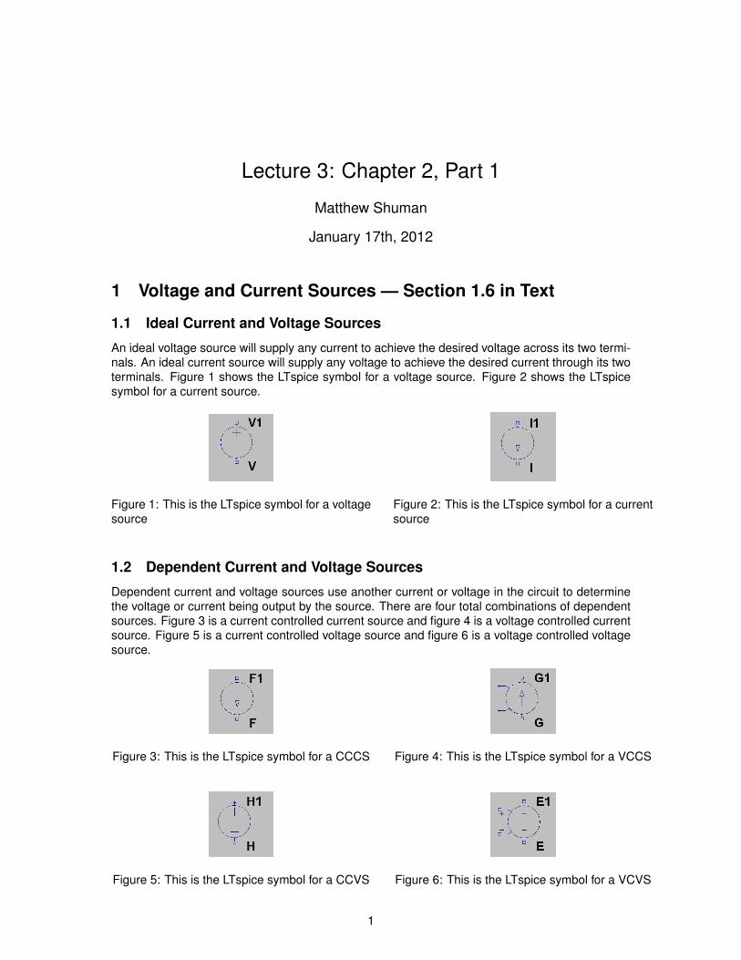
1 Voltage and Current Sources — Section 1.6 in Text
1.1 Ideal Current and Voltage Sources
An ideal voltage source will supply any current to achieve the desired voltage across its two termi-nals. An ideal current source will supply any voltage to achieve the desired current through its twoterminals. Figure 1 shows the LTspice symbol for a voltage source. Figure 2 shows the LTspicesymbol for a current source.
Figure 1: This is the LTspice symbol for a voltagesource
Figure 2: This is the LTspice symbol for a currentsource
1.2 Dependent Current and Voltage Sources
Dependent current and voltage sources use another current or voltage in the circuit to determinethe voltage or current being output by the source. There are four total combinations of dependentsources. Figure 3 is a current controlled current source and figure 4 is a voltage controlled currentsource. Figure 5 is a current controlled voltage source and figure 6 is a voltage controlled voltagesource.
Figure 3: This is the LTspice symbol for a CCCS Figure 4: This is the LTspice symbol for a VCCS
Figure 5: This is the LTspice symbol for a CCVS Figure 6: This is the LTspice symbol for a VCVS
1
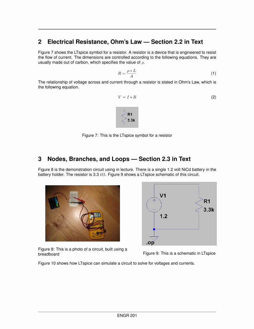
2 Electrical Resistance, Ohm’s Law — Section 2.2 in Text
Figure 7 shows the LTspice symbol for a resistor. A resistor is a device that is engineered to resistthe flow of current. The dimensions are controlled according to the following equations. They areusually made out of carbon, which specifies the value of ρ.
R =ρ ∗ LA
(1)
The relationship of voltage across and current through a resistor is stated in Ohm’s Law, which isthe following equation.
V = I ∗R (2)
Figure 7: This is the LTspice symbol for a resistor
3 Nodes, Branches, and Loops — Section 2.3 in Text
Figure 8 is the demonstration circuit using in lecture. There is a single 1.2 volt NiCd battery in thebattery holder. The resistor is 3.3 kΩ. Figure 9 shows a LTspice schematic of this circuit.
Figure 8: This is a photo of a circuit, built using abreadboard Figure 9: This is a schematic in LTspice
Figure 10 shows how LTspice can simulate a circuit to solve for voltages and currents.
ENGR 201
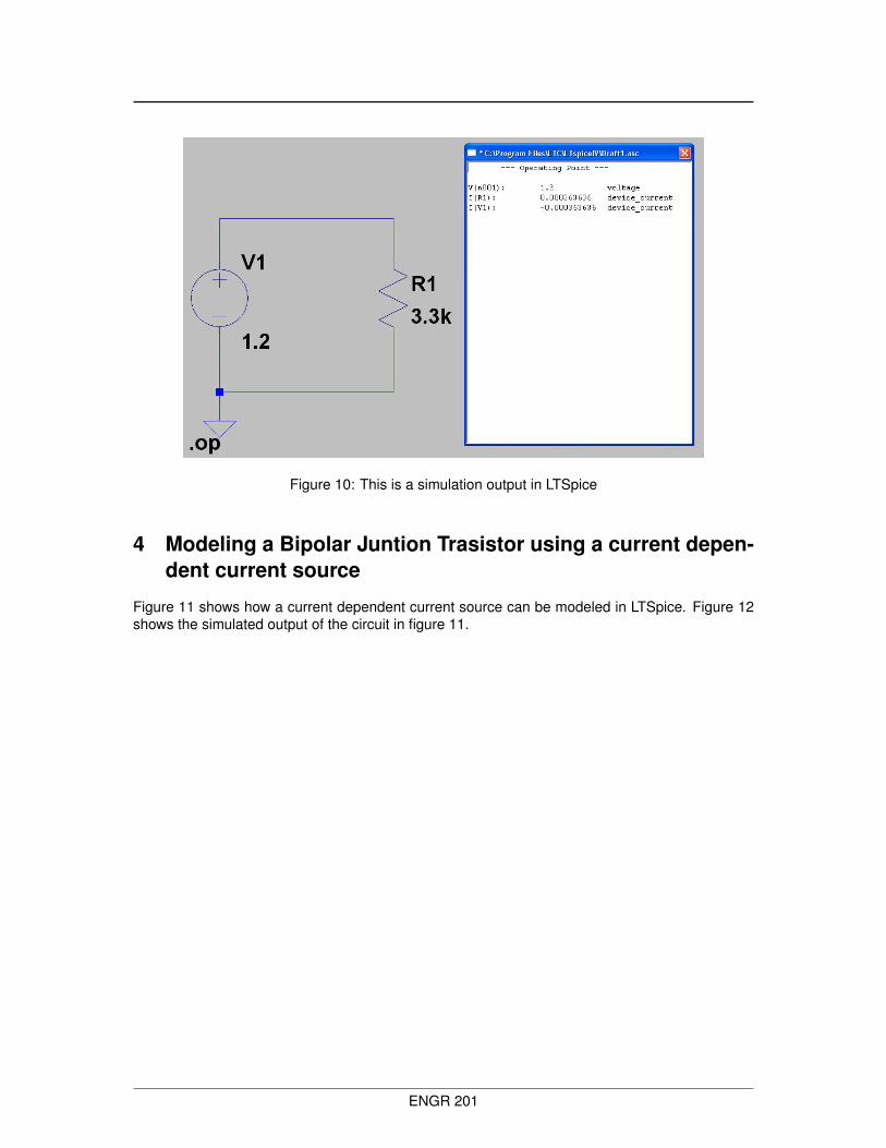
Figure 10: This is a simulation output in LTSpice
4 Modeling a Bipolar Juntion Trasistor using a current depen-dent current source
Figure 11 shows how a current dependent current source can be modeled in LTSpice. Figure 12shows the simulated output of the circuit in figure 11.
ENGR 201
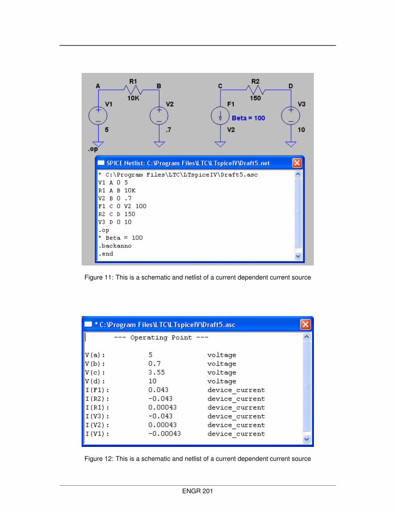
Figure 11: This is a schematic and netlist of a current dependent current source
Figure 12: This is a schematic and netlist of a current dependent current source
ENGR 201