laplace operator ‘s’ reminder from engr201 know how components behave in an instant of time...
TRANSCRIPT

Laplace operator ‘s’
Reminder from ENGR201
Know how components behave in an instant of time
Consider differential response
Combine and simplify into standard forms
Integration by lookup table determines long-term response
t domain s domain
Signals
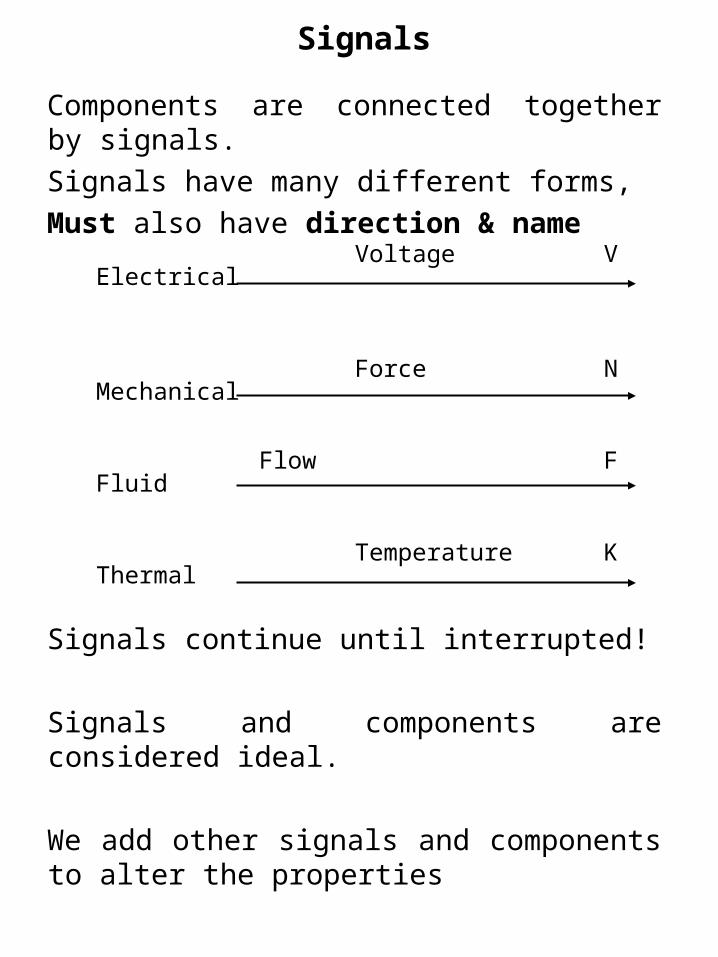
Components are connected together by signals.
Signals have many different forms,
Must also have direction & name
Signals continue until interrupted!
Signals and components are considered ideal.
We add other signals and components to alter the properties
Voltage VElectrical
Force NMechanical
Flow FFluid
Temperature KThermal

We wish to know how the output signal varies with an input signal for a fixed (invariant) system
Consider a spring (constant k), with force F applied to stretch it a distance x
We may plot two signals against each other invariant of time (system relationship)
Signals
Distance xForce F
Distance x
Force F

System constants are time invariant for the given system
We now consider a different system as the spring has been changed.
However, the analysis stays the same
Constants
Distance x
Force F
Spring constant k = 1
Distance x
Force F
Now k = 2

Systems
In order to analyse a system:We identify an input signal
[a variable]Using block diagram components
[Basic block Summing junction Take-off point]
We combine internal signals[modified variables]
To produce the output signal[another variable].
The Input-Output relationship may then be determined

Flow F1 F1 + F2
Fluid F2
Components
Summing junction
+ and/or – the system signals
Voltage V1 V1 – V2
Electrical V2
+ _
++
Up to three inputs and only one output

Components
Block•or / or function of the system signal
Variables Constants
Input Direction Output
Only one input and only one output
Force F Distance x
Spring
Current I VR
1 / k

Components
Take-off point
The system signal can be used elsewhere,
but is not affected by the split
Voltage V1 V1
Electrical
V1
Only one input and many outputs

Mechanical Components
We know that distance (x) is related to velocity (v) is related to acceleration (a) through differentiation.
It gets messy writing all the time!Therefore, we will write ‘s’ instead.
x = xv = sxa = sv = s2x
NB, Both with respect to the variable
txx
dt
tdxv
2
2
dt
txd
dtdt
tdxd
dt
dva
dt
d
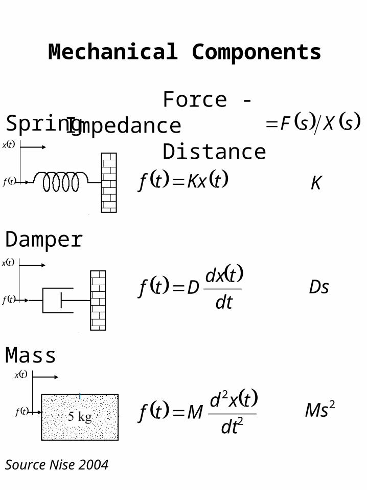
Mechanical Components
Spring
Damper
Mass
Source Nise 2004
Force - ImpedanceDistance
tKxtf
dt
tdxDtf
2
2
dt
txdMtf
tf
tx
tf
tx
tf
tx
sXsF
K
Ds
2Ms

Capacitor
Resistor
Inductor
Source Nise 2004
Electrical Components
Voltage - ImpedanceCurrent
tRitv
dt
tdiLtv
tv
ti
sIsV
R
Ls
tv
ti
tv
ti
tiC
tv1
sC
11

Assume armature inductance is negligible.
Armature resistor:
Back emf of motor:
Torque proportional to armature current:
Torque is opposed by the inertia torque:
Hint: apply Kirchhoff’s voltage law to the armature circuit
We need to form a relationship between input voltage and output velocity:
R2-D2 Motor System
Rba vvv
sVa
sIa
sVb
T
aTiKT eb Kv aaR Riv
dt
dJT

Combine components
Components of Motor System
sIRsV aR
sKsV eb
sJssT
bV
RV
eK
RI
Js
T
+_
bV
aV RVRba vvv
aTiKT
eb Kv
aaR Riv
dt
dJT
sIKsT TTI TK

Reduce block diagram:
Block Diagram of Motor System
bV
aV+_
1
1
sKKJR
K
te
a
e
1.
2.
3.
eKbV
1/R TK Js1
bV
aV+_
eKbV
sJR
K
a
T
aV

Output linked to input:
Can be expressed much more simply!:
Where:
Time Constant:
Gain:
Transfer Function of System
1
1
sKKJR
K
V
te
a
e
a
11
sT
K
Va
te
a
KK
JRT 1
eKK
1

Past Assignment question
Determine the block diagram for each system?
Source Nise 2004