lecroy lw410b/lw420b arbitrary waveform generator€¦ · single: outputs 1 repetition of the...
TRANSCRIPT
LW
41
0A
/4
20
A A
WG
S
THE CHOICE IS YOURS:SPECIFY THE WAVEFORM,AND LET THE LW420BHANDLE THE DETAILS OR
TAKE CONTROL YOURSELFWith the WaveStation, you need noawareness of the sample clock periodor the particular reconstruction filterbeing used. All the LW420B needs isyour waveform’s time and voltage rela-tionships. No matter which of the manyavailable tools you use to specify thewaveform, the LW420B will generatethe output using the optimum combi-nation of sample clock rate and filterbandwidth. The filters automaticallyselected will assure that aliasing doesnot take place and that all the timingrelationships within the waveform willbe precisely maintained. Full control ofthe clock and bandwidth filters is therefor those who need it.
LeCroyWaveStationLW410B/LW420BArbitraryWaveformGenerator
MAIN FEATURES• 100 ps Feature Placement
and Single Point Resolution
• 1 and 2 Channels Versions
• Generate Complex, PhaseSynchronized Signals on TwoChannels.
• Continuously Variable SampleClock From 6 MHz to 400MHz with 1 Hz Resolution
• Live Control of Edge Timingand Pulse Amplitude WhileViewing Output Wave
• Stand Alone Design, no PCRequired
• 8 Bits of Vertical Resolution
• Up to 1 Mbyte of PlaybackWaveform Memory perChannel
• FastSwitch Group SequenceTest Mode Provides RandomAccess to Sequences With anAccess Time of Under 11 ms
• Internal Disk Drives forProject, Sequence, andWaveform Storage
• Digital Output OptionProvides 8-Bit TTL and ECLDigital OutputsCorresponding to the Waveon the Analog Output. SpecialDigital Editing Mode Usefulin Creating Data Patterns.
• CE, UL and cUL Certified
http://www.lecroy.co
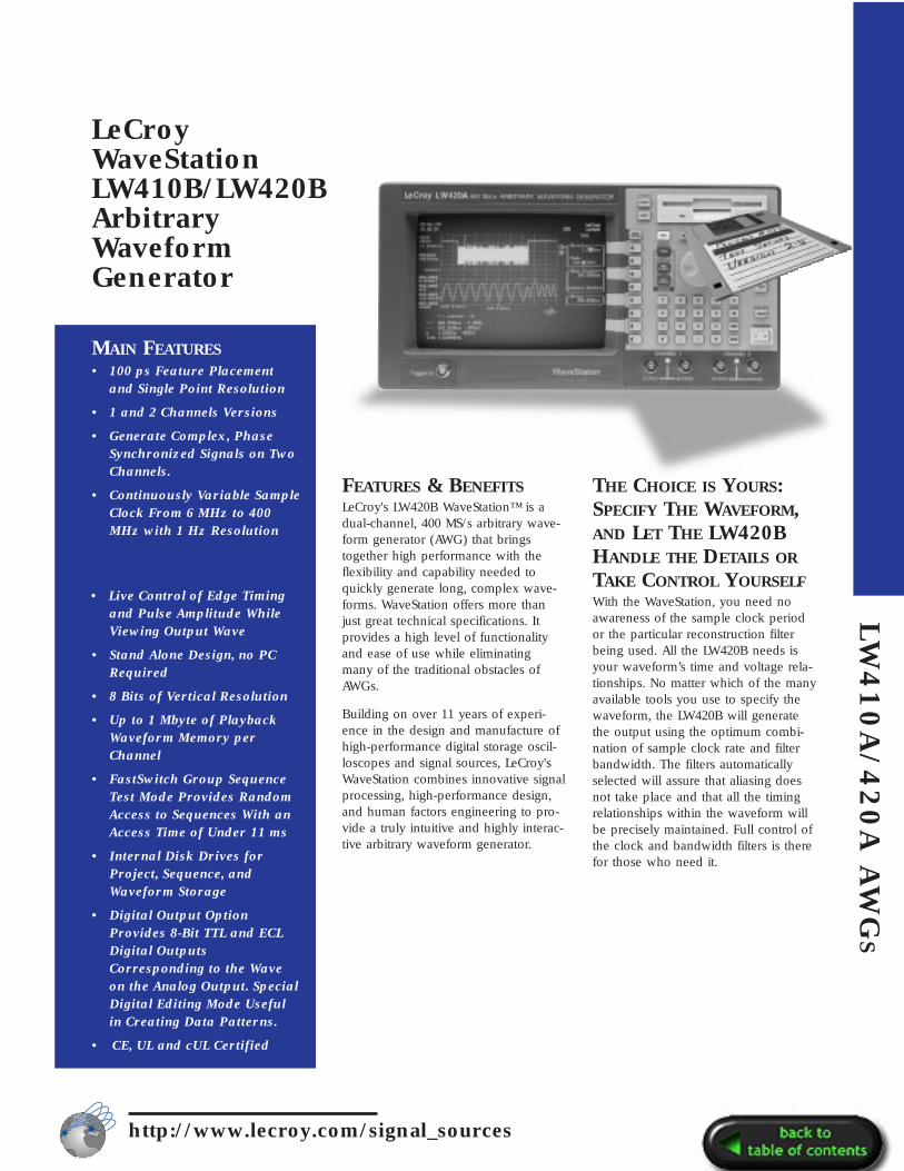
FEATURES & BENEFITSLeCroy's LW420B WaveStation™ is adual-channel, 400 MS/s arbitrary wave-form generator (AWG) that bringstogether high performance with theflexibility and capability needed toquickly generate long, complex wave-forms. WaveStation offers more thanjust great technical specifications. Itprovides a high level of functionalityand ease of use while eliminatingmany of the traditional obstacles ofAWGs.
Building on over 11 years of experi-ence in the design and manufacture ofhigh-performance digital storage oscil-loscopes and signal sources, LeCroy'sWaveStation combines innovative signalprocessing, high-performance design,and human factors engineering to pro-vide a truly intuitive and highly interac-tive arbitrary waveform generator.
m/signal_sources
vary the signal’s amplitude, the signal-to-noise ratio is maintained.
400 MS/S MAXIMUM
CLOCK RATE, 1 MPOINT
WAVEFORMS, AND
SYNTHESIZER TIMEBASE
WITH TWO PHASE-SYNCHRONIZED CHANNELSA maximum sample rate of 400 MS/s,up to 1 Mbyte of waveform memory, aprecise timebase, and single point reso-lution gives you the power you needto generate the most demanding, com-
SIG
NA
LS
OU
RC
ES
REAL-TIME WAVEFORM
MANIPULATION LETS
YOU QUICKLY CONTROL
THE WAVESHAPE—EASILY
AND INTERACTIVELY—WHILE VIEWING ON THE
INTERNAL CRT DISPLAYSelect a section of the waveform usingthe time cursors, then select one of aset of waveform manipulation opera-tions (e.g. move feature, delay, ampli-tude) and turn the knob! That is howeasy it is to continuously modify all orpart of a waveform. Time shifts, assmall as 100 ps, amplitude variationson a peak, or changes in signal dura-tion are instantly reflected in the outputsignal. Margin testing or characteriza-tion, with the most complex wave-forms, has never been so easy.
WAVEFORM CREATION HAS
NEVER BEEN EASIERWaveforms can be selected fromlibraries of traditional functions orapplication specific waveforms. Theycan also be created using equations orimported from external sources such asoscilloscopes, or from computer pro-grams and simulator output files. Oncewaveforms are created or captured,they can be further modified usinginternal waveform (array) math pro-cessing. The waveform math functionsinclude basic arithmetic operations,smoothing, integration, differentiation,and convolution.
The highly developed waveform edit-ing capability uses advanced signalprocessing to provide bandlimited cut,paste, insert and offset operations withminimal editing artifacts. Single sampleresolution, further simplifying wave-form creation, is allowed since wave-forms are not constrained to 8 samplemultiples as with most other AWGs.
To simulate real-world signals, theinternal, asynchronous, wide-bandnoise generator is easily used to addcontrolled amounts of noise to yoursignals—simply dial in the noise levelas a percentage of your signal’s ampli-tude. A real timesaver is that if you
plex stimuli. The timebase combining 3 ppm accuracy and 1 ppm/year stabil-ity assures that the waveforms you testyour systems with next year will be thesame as the ones you use today. Lowsingle sideband phase noise and a
FLEXIBLE WAVEFORM
IMPORT AND TRANSFERPull waveforms directly from most digi-tal scopes; Connect a GPIB cablebetween the LW420B and your digitaloscilloscope. Select your scope from alist of commonly available models andbegin importing waveforms.
Waveforms of up to 1 Mpoints in ASCIIor from programs such as MathCad,MATLAB, PSPICE, IQSIM, TOPSIM andothers can be imported from the floppydrive. You can also use a sharewareprogram from LeCroy to convert yourfiles to DIF format and transfer directlyover the GPIB to the LW420B.
When importing or transferring files,you have the choice of over samplingor importing the points exactly as theyare. Once in the WaveStation, all themodification, editing and math toolscan be used to put the waveform inthe shape you need for your task.
FAST SWITCH GROUP
SEQUENCE INCREASES TEST
FLEXIBILITY AND
MINIMIZES TEST TIMELeCroy’s Fast Switch Group Sequencecapability enables you to switchbetween many different pre-loadedwaveforms in less then 11 ms.Waveforms will continually play until asequence advance is received from thefront panel or a remote command.Choose to auto advance from sequenceto sequence or choose to jump to thenth sequence in the group. Generate acontinuous output of a sequenceselected from the group, or use theexternal trigger input to initiate a burstor single shot of the selected sequence.
1 Hz frequency resolution over a con-tinuous 6 kHz–400 MHz range providethe flexibility and capability needed togenerate even the most complex anddemanding waveforms.
FULLY INTEGRATED AWGINCLUDES HIGH
PERFORMANCE PROCESSOR,INTERNAL HARD DISK
DRIVE, AND BUILT-IN 9INCH CRTWaveStation provides all the powerneeded to work with long and com-plex waveforms. A built-in hard diskdrive, a 486 processor, up to 24 Mbytesof RAM, and a large internal mono-chrome VGA display make the LW420Aa fast, responsive instrument ideallysuited for the interactive graphicaloperations required in a high-perfor-mance AWG.
DIGITAL OUTPUT OPTIONThe Digital Output option provides 8-bit TTL and ECL digital outputs corre-sponding to the current value of theChannel–1 analog output. The latcheddigital data is held for the duration ofthe sample clock. The digital data,
including the sample clock and itscomplement, are available via rear-panel connectors. The special digitalediting mode is useful for creating andediting byte wide data patterns orselected bits and the standard “cut andpaste” tools available for analog wave-forms can also be used.

LW
41
0A
/4
GENERATOR MODEStandard Function Waveforms
Sine, 1 Hz–100 MHzSquare, 1 Hz–50 MHzTriangle, 1 Hz–25 MHzRamp, 1 Hz–25 MHzPulse, (period) 20 ns - max. memory DCFrequency Sweep, Linear / LogMultitone, 1–10 tones,1 Hz–100 MHz
Special Waveform Generation ModeIMD - Intermodulation distortion test waveform: Select center frequency, 1-15 tone pairs, tone spacing, resolu-tion, offset from center frequency.
ARBITRARY FUNCTIONS
Waveform CreationInteractive Graphical editor on internal 9” diagonal CRT—8.5” viewable.
Standard FunctionsSine, Square, Triangle, Ramp, Pulse, DC
Equation EditorWaveform (array) MathWaveform Import From
Digital OscilloscopeFloppy Disk
Feature Time Resolution:100 ps @ 400 MHz
Available memory:256 k/ch standard1 Mpoint optional
20
A A
WG
S
SEGMENTED WAVEFORMSMinimum segment length: 64 pointsMaximum segment length:Up to available memory (1 Mpoint withmemory option installed).Segment length resolution: 1 point
Number of links: 512 for 256k memory2048 for 1M memory
http://www.lecroy.co
WAVEFORM OUTPUT
CHARACTERISTICSOutput channels:LW410A – 1 ChannelLW420A – 2 Channel
Output Impedance: 50 Ω, ±5%
DC Accuracy:2% ±40 mV > 500 mV2% ±15 mV < 500 mV
Vertical resolution: 8 bits
Minimum output voltage: 10 mV p-p into 50 Ω
Maximum output voltage: 10 V p-p into 50 Ω
Offset voltage range: ±5 V into 50 Ω.The output voltage (signal + offset)must be in the range ±5 V into 50Ω.
Offset voltage resolution: 0.05% offull scale
Output bandwidth: 100 MHz (-3dB)(widest bandwidth)
Total harmonic distortion:For sinusoidal output of <5 V p-p;
< -45 dBc (-50 dBc typical) for frequencies: <1MHz
< -35dbc (< -45 dBc typical) forfrequencies: 1 MHz–20 MHz
< -25 dBc (< -40 dBc typical) for frequencies: >20MHz–50 MHz, predominantly 2nd harmonic
Spurious & non-harmonic distortion: < -60 dBc for frequencies <1 MHz
Signal-to-noise ratio: >40 dB (-45 typ-ical) for output amplitudes >100 mV @0 offset
Transition times: 5.0 ns, 10%–90% atwidest bandwidth.
Overshoot and ringing: <8% of stepsize max. 3% typical
m/signal_sources
Settling time: <50 ns to within 2% ofstep size at widest bandwidth.
Inter-channel crosstalk: <1%
Ch 1 to Ch 2 skew: <1 ns for identicalwaveforms in each channel (widestbandwidth).
Output protection: ±20 V
Output filtering: Gaussian filters withthe following cutoff frequencies can beselected; 100 MHz , 10 MHz, 1 MHz ,100 kHz , 10 kHz
SAMPLE CLOCK
CHARACTERISTICS(with internal 10 MHz reference)Sample Clock: 6 kHz–400 MHz Resolution: 1 HzAccuracy: <3 ppm over operating tem-perature range.Stability: aging <1 ppm/yearSSB Phase Noise: < -90 dBc/Hz @ 10KHz offset for a 10 MHz sine wave atthe output
TRIGGERING
CHARACTERISTICSTrigger slope: Positive or NegativeTrigger input impedance: 50 Ω ± 5%Threshold range: ±2.5VThreshold resolution: 20 mVThreshold accuracy: 100 mV Threshold sensitivity: 50 mV p-pMinimum pulse width: 5 nsProtection: ±5 V
TRIGGER MODESContinuous: Runs continuously
Single: Outputs 1 repetition of thewaveform for each trigger received.Triggers received while the waveformis still running are ignored.
Burst: Outputs the selected waveforma programmable number of times inresponse to a trigger. The maximumnumber of repetitions for a burst is4,095. Triggers received while the burstis running are ignored.
Gated: The waveform starts on the
External 10 MHz reference: Rearpanel BNC connector for input of anexternal reference clock. 400 mV p-pto 5 V p-p into 50 Ω.
SIG
NA
LS
OU
RC
ES
leading edge of the gate signal andstops on completion of the waveformcycle occurring at the trailing edge ofthe gate signal.
AUXILIARY OUTPUTS10 MHz reference: ± 3 ppm accuracyAmplitude (high): 1.6 V into 50 Ω.Amplitude (low): 0.2 V into 50 Ω.
Markers: Select Edge or ClockEdge: 1 bit memory—set up to 128edge transitions—ECL or TTL levelsClock: Frequency up to one half thesample clock rate.
Protection: Outputs protected to ±5 V.
Channel 1 Digital Output Optional:8 bits and clock with TTL and ECLlogic levels available simultaneously.
Noise In: From rear panel BNC connectors.
TRIGGER DELAYMinimum delay time: 35 ns ±3.5 ns+5 sample clocks (fixed)
Maximum delay time: 10 s at highestclock rate to 100k s at lowest clockrate.
Delay resolution: 1 sample clock.Delay is in units of seconds. Whenoperating from the front panel, the res-olution is set in increments of the sam-ple clock period.
Delay accuracy: Same as sample clock+ minimum delay time.
Delay jitter: 1 sample clock.
TRIGGER SOURCESManual: Front panel push-button.External: Front panel BNC connector.GPIB: A trigger command may beissued over the GPIB bus.
MASS STORAGE3.5” 1.44 MB DOS format floppy drive400 MB internal hard disk drive.
AUXILIARY INPUTS
HARD COPY OUTPUTSSupported Printers include:Epson MX/FXEpson LQHP LaserJet IIHP ThinkJet
PROGRAMMABILITY
GPIB IEEE 488.2 compatible.Compliant with SCPI programming lan-guage. Capable of initiating and con-trolling waveform transfer from digitaloscilloscopes by simply connecting aGPIB cable (no computer required).
MECHANICALDimensions:14.92”W x 7.67”H x 19.58”D (37.9 cm x 19.5 cm x 49.7 cm)
Weight: 27.6 lbs (12.5 kilograms)
ENVIRONMENTALTemperature: 5º to 35º full specifica-tions; 0º to 40ºC operating;-20º to 70ºC non-operating.
Humidity: 10% to 90% relative, non-condensing
POWER:Autosensing90-132/180-250 V AC47-63 Hz
4 amps @ 115 V AC (20 amps cold start surge)
2 amps @ 230 V AC (40 amps cold start surge)
Warranty: One Year
LW400 SERIES - ORDERING INFORMATION
WAVEFORM GENERATORS: PRODUCT CODESingle Channel 400 MS/s Arbitrary Waveform Generator LW410B1 Megasample memory - 1 channel LW410-ME2Dual Channel 400 MS/s Arbitrary Waveform Generator LW420B1 Megasample memory - 2 channels LW420-ME2Rackmount Adapter for LW410/420 LS-RMTransit Case for LW410/420 LS-TRANSSoft Carrying Case for LW410/420 LS-SOFTOperators Manual for LW410/420 - Included with LW410/420 LW400-OMRemote Programming Manual for LW410/420 - Incl. with LW410/420 LW400-RPGService Manual for LW410/420 LW400-SMDigital Output - Channel 1 Only LW400-09A5 NIST Calibrations on any LW400 Series AWG LW4XX-C5NIST Calibration on LW400 Series LW4XX-CCMIL-STD Calibration on LW400 Series LW400-CCMIL5 Year Warranty and NIST Calibration on LW400 Series LW4XX-T55 Year Warranty on LW400 Series AWG LW4XX-W55 Year Warranty and MIL-STD 45662A Calibration on LW400 Series LW4XX-R5/MIL