lbi-39140 service section orion™ 29-50 mhz mobile radio
TRANSCRIPT
LBI-39140
ericssonzericssonz
SERVICE SECTION
ORION™29-50 MHz
SCAN AND SYSTEMMOBILE RADIO
TABLE OF CONTENTS
PageDESCRIPTION ........................................................................................................................................................2
INITIAL MEASUREMENTS .................................................................................................................................2TRANSMITTER ..............................................................................................................................................2RECEIVER .......................................................................................................................................................2
MAINTENANCE .....................................................................................................................................................3PREVENTATIVE ............................................................................................................................................3DISASSEMBLY PROCEDURES ...................................................................................................................4
ALIGNMENT PROCEDURES ..............................................................................................................................6INTRODUCTION ............................................................................................................................................6TRACKING DATA ..........................................................................................................................................8TEST FREQUENCIES ....................................................................................................................................8SETTING TRACKING DATA .......................................................................................................................9
TRANSMITTER ALIGNMENT ............................................................................................................................10
PA TRANSISTOR REPLACEMENT ...................................................................................................................10
RECEIVER ALIGNMENT ....................................................................................................................................11TEST EQUIPMENT REQUIRED ..................................................................................................................11ADJUSTMENT PROCEDURES ....................................................................................................................11SQUELCH ADJUSTMENT ............................................................................................................................12
TROUBLESHOOTING GUIDE ............................................................................................................................12INTRODUCTION ............................................................................................................................................12MICROPHONICS ............................................................................................................................................12SERVICEABLE PARTS ..................................................................................................................................13
DIAGNOSTIC PROCEDURES .............................................................................................................................14ADDITIONAL TOOL REQUIRED ...............................................................................................................15TRANSMITTER ..............................................................................................................................................15RECEIVER .......................................................................................................................................................16CONTROL UNIT .............................................................................................................................................17GENERAL ........................................................................................................................................................18ERROR CODES ...............................................................................................................................................18

LBI-39140
2
DESCRIPTION
This section contains the information required toservice the ORION Low Band two-way FM mobile radio.Included are disassembly procedures, alignmentprocedures and troubleshooting information (see Table ofContents).
This radio is adjusted by setting personalityparameters stored in the radio computer memory.Therefore, all radio alignment procedures require the useof a Personal Computer (PC) (IBM PC, or equivalent)along with an Ericsson Programming Interface TQ3370,and ORION PC Programming cable TQ3377. EricssonPC Programming Software Version 3.00 or later is also
This radio is designed to be serviced by replacementof modules and/or circuit boards. As such, there are veryfew serviceable component parts contained on any of thecircuit boards within the radio. Normally, defective boardsshould be replaced and returned to an Authorized EricssonService Center. Any serviceable parts are listed in thetroubleshooting guide for the individual circuit boards.
INITIAL MEASUREMENTS
After the radio has been installed as described in theInstallation Manual, the following measurements shouldbe made by a certified electronics technician and recordedfor future reference:
TRANSMITTER
• RF power into 50 ohm resistive load
• Forward power into antenna
• Reflected power from antenna
• Carrier frequency
• Modulation deviation
RECEIVER
• 12 dB SINAD sensitivity
Copyright © March 1995, Ericsson Inc.

LBI-39140
3
MAINTENANCE
PREVENTIVE MAINTENANCE
To ensure high operating efficiency, and to prevent mechanical and electrical failures frominterrupting system operations, routine checks should be made of all mechanical and electricalequipment at regular intervals. This preventive maintenance should include the checks as listed inTable 1, Maintenance Checks.
Table 1 - Maintenance Checks
MAINTENANCE CHECKS INTERVAL
CONNECTIONS - Ground connections and connections to the voltage source should beperiodically checked for tightness. Loose or poor connections to the power source willcause excessive voltage drops and faulty operation. When ground connections are notmade directly to the battery, the connection from the battery to vehicle chassis must bechecked for low impedance. A high impedance may cause excessive voltage drops andalternator noise problems.
Every 6months
ELECTRICAL SYSTEM - Check the voltage regulator and alternator or generatorperiodically to keep the electrical system within safe and economical operating limits.Over voltage is indicated when the battery loses water rapidly. Usage of 1 or 2 ounces ofwater per cell per week is acceptable for batteries in continuous operation. A weakbattery will often cause excessive noise or faulty operation.
AsRequired
MECHANICAL INSPECTION - Since mobile units are subject to constant shock andvibration, check for loose plugs, nuts, screws, and parts to make sure that nothing isworking loose. Be sure that all screws are properly torqued.
Every 6months
ANTENNA INSPECTION - The antenna, antenna base, and all contacts should be keptclean and free from dirt or corrosion. If the antenna or its base should become coated orpoorly grounded, loss of radiation and a weak signal will result.
Every 6months
ALIGNMENT - The transmitter and receiver meter readings should be checkedperiodically, and the alignment "touched up" when necessary. Refer to the applicableAlignment Procedure and troubleshooting sheet for typical voltage readings.
AsRequired
FREQUENCY CHECK - Check transmitter frequency and deviation, as required by theFCC. Normally, these checks are made when the unit is first put into operation, after thefirst six months, and once a year thereafter.
AsRequired
NOTE

LBI-39140
4
DISASSEMBLY PROCEDURE
To Remove Unit From Mounting Bracket
1. Remove the microphone, power and accessory/remotecontrol cables, as required.
2. Remove the lock screws at the side of the radio unit,using a #20 TORX® driver.
3. Pull the radio out of the mounting bracket.
To Gain Access To The Circuitry For Servicing
RF Power Amplifier Module:
1. Remove the waterproof cover on bottom of themodule, using a #20 TORX® driver. Note that thefour mounting screws are captivated to the cover.
2. Remove the inner shield by pulling with the attachedhandle.
Transceiver (TXRX) Module:
1. Remove the waterproof top and bottom covers using#20 TORX® driver. Four cover mounting screws arelocated on the bottom of the module. These screwsare captivated to the bottom cover.
2. To expose the Logic/Audio/455 kHz IF circuitry,remove the shield on top of the module by pullingwith the attached handle.
3. To expose the Exciter/RX front end circuitry, removethe shield on the bottom of the module by pullingwith the attached handle.
The VCO/Synthesizer circuitry is exposed byremoving screws from the shield casting, alsolocated on the bottom of the module. However, thisis not recommended, except in extreme situations.If the shield is removed, it should be replacedusing exact screw torque and installation sequencegiven in maintenance manual LBI-38909.
Control Head (Remote Mounting)
1. Disconnect the remote control and accessory cables,using a small flat blade screwdriver.
2. Remove the two side mounting screws from themounting bracket. Carefully remove the control headassembly from the bracket.
3. Disengage the four captivated screws on the rear half, also known as the Remote Interface Adapter (RIA)of the control head. Slide the two halves apart, usingcare not to damage the black "O-Ring" moisturegasket attached to the RIA..
4. Disconnect flex circuit PC2 from connector J2, bycarefully disengaging the locking tab from each sideof the connector with a jeweler's screwdriver ortweezers. Use extreme care not to damage plattingruns or surface mounted components on the printedwire board during this procedure.
To Reassemble The Radio After Service
Essentially follow the reverse of the aboveinstructions. However, in order to preserve moisture seals,be sure to follow the EXACT torque and sequencingspecifications for screw engagement during reassembly.These specifications are given in maintenance manualLBI-38909.
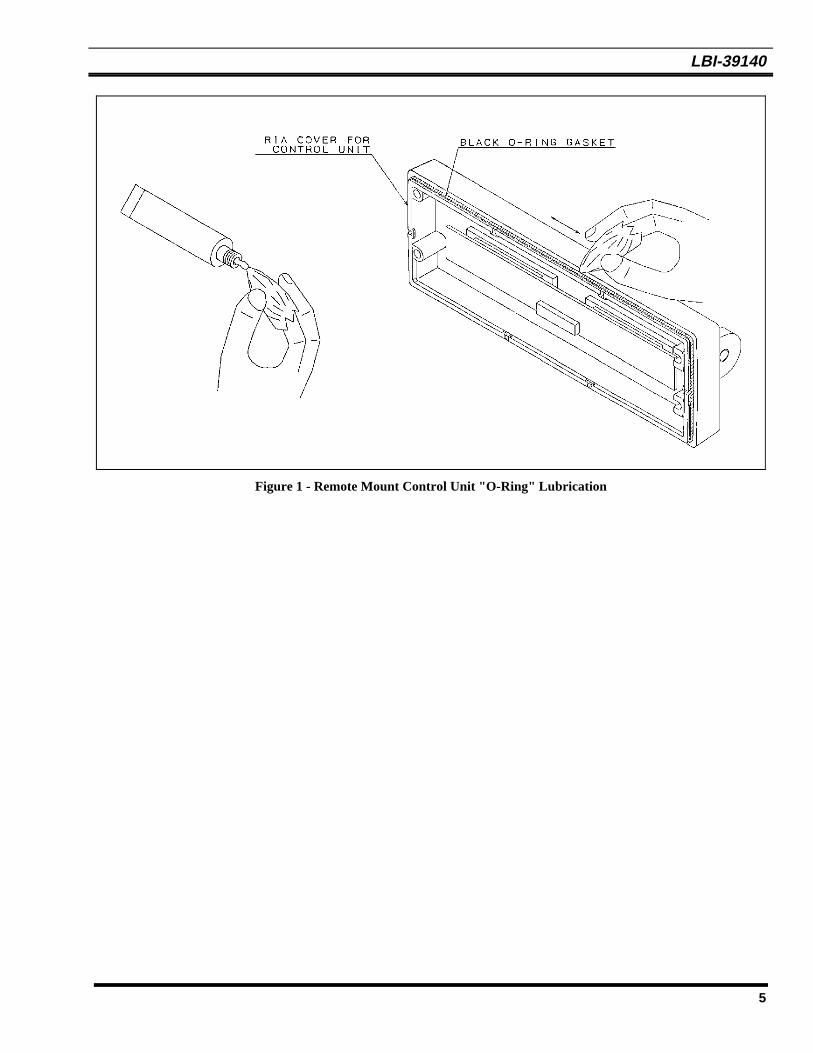
For re-assembly of the Control Units (Front andRemote Mounting) Revision "A" or later, be surethe black "O-Ring" is lubricated properly with"HIVAC-G" silicone grease (See Figures 1A and1B for instructions).
Steps:
1. Remove dust and dirt from the black O-Ring gasket.
2. Apply proper amount of the silicone grease to a clothas shown in Figures 1A and 1B.
3. Put the silicon grease on the black O-Ring gasket,covering the surface of the gasket evenly (see Figure1A and 1 B).
NO Fibers of cloth must remain on the gasketafter the silicone is applied.
CAUTION
4. Wipe out protruded silicone grease form theRear/RIA Cover.
NOTE
NOTE
LBI-39140
5
Figure 1 - Remote Mount Control Unit "O-Ring" Lubrication

LBI-39140
6
ALIGNMENT PROCEDURES
INTRODUCTION
All operations of this radio are controlled by anembedded digital computer, which is programmed with apersonality unique to the customer. In order to align andtest the radio, it must be programmed with a specific testpersonality, which will allow conventional operation oncertain test frequencies. Certain tests can be carried out byaltering the personality. Furthermore, certain commands,known as Test Mode Commands, cause the radio toperform specific test functions. These will be noted asrequired in the following alignment and troubleshootinginstructions.
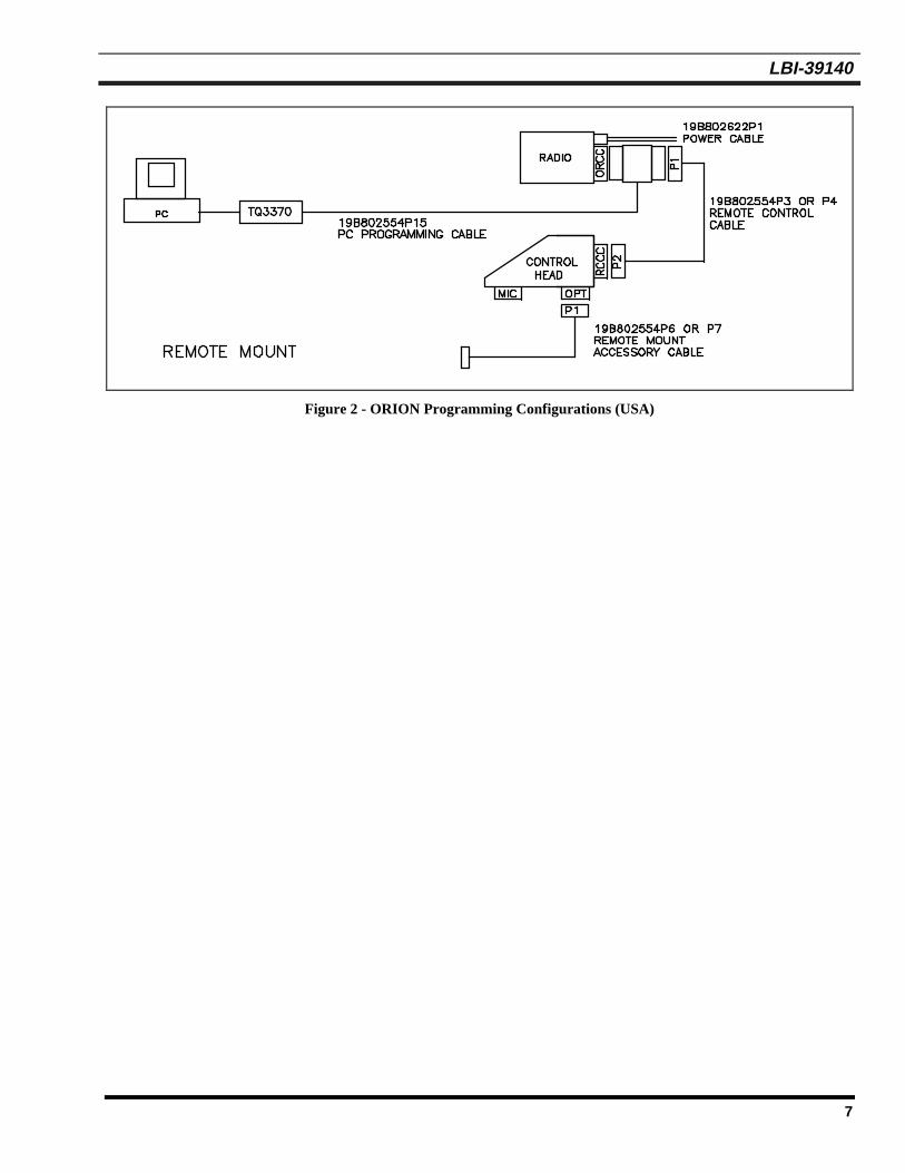
In order to program an ORION personality, the radioand control unit must first be connected to a personalcomputer through PC Programming Cable and HardwareProgramming Interface TQ3370, in one of theconfigurations shown in Figure 2 or 3. Accessories maybe connected to the appropriate accessory cable19B802554P1-P4 as needed.
The PC must be equipped with the Ericsson GE PCProgramming Software, Version 4.0 or later. It is assumedin this manual that the Service Technician is familiar withthe operation of the PC Programming Software programs"EDACS3" and "MRKMAINT" . Consult the PCProgramming Software manuals for further detailsregarding this software.
Before bench testing the radio, be sure of theoutput voltage characteristics of your benchpower supply.
To protect the transmitter power outputtransistors from possible instant destruction, thefollowing input voltages must not be exceeded.
Transmitter unkeyed 16.5 Volts
Transmitter keyed(50 ohms resistive load) 16.3 Volts
Transmitter keyed(No load or non-resistive load) 14.0 Volts
These voltages are specified at the normalvehicle battery terminals of the radio and takethe voltage drop of standard cables intoaccount. The voltage limits shown for a non-optimum load is for "worst case" conditions.For antenna mismatches likely to beencountered in practice, the actual limit willapproach the 16.3 Volt figure.
Routine transmitter test should be performed atEIA Standard Test Voltages (13.6 Vdc forloads of 6 to 16 amperes; 13.4 Vdc for loads of16 to 36 amperes). Input voltages must notexceed the limits shown, even for transientpeaks of short duration.
Many commonly used bench power suppliescannot meet these requirements for loadregulation and transient voltage suppression.Bench supplies which employ "brute force"regulation and filtering (such as Lapp Model73) may be usable when operated in parallelwith a 12 Volt automotive storage battery.
CAUTION
LBI-39140
7
Figure 2 - ORION Programming Configurations (USA)
LBI-39140
8
TRACKING DATA
The radio personality contains certain informationbytes known as Tracking Data, which allow the radiocomputer to calibrate transmitter power , modulationdeviation and squelch threshold. Normally, noadjustments need be made to the radio to maintainspecified limits for the above parameters, since the radiocomputer makes the necessary adjustments using theTracking Data established at the factory. However, shouldthe transmitter PA, synthesizer or logic circuit boards bereplaced, it may be necessary to alter the Tracking Data tore-set these parameters properly. Furthermore, if the
Tracking Data is lost, specialized procedures are requiredto load new Tracking Data. Therefore, it is VERYIMPORTANT to establish a record of the Tracking Dataof every radio as it is received from the factory. Thefrequencies at which Tracking Data is established aregiven in the "Test Frequencies" section.
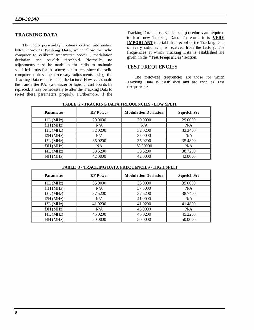
TEST FREQUENCIES
The following frequencies are those for whichTracking Data is established and are used as TestFrequencies:
TABLE 2 - TRACKING DATA FREQUENCIES - LOW SPLIT
Parameter RF Power Modulation Deviation Squelch Set
f1L (MHz) 29.0000 29.0000 29.0000f1H (MHz) N/A N/A N/Af2L (MHz) 32.0200 32.0200 32.2400f2H (MHz) N/A 35.0000 N/Af3L (MHz) 35.0200 35.0200 35.4800f3H (MHz) NA 38.50000 N/Af4L (MHz) 38.5200 38.5200 38.7200f4H (MHz) 42.0000 42.0000 42.0000
TABLE 3 - TRACKING DATA FREQUENCIES - HIGH SPLIT
Parameter RF Power Modulation Deviation Squelch Set
f1L (MHz) 35.0000 35.0000 35.0000f1H (MHz) N/A 37.5000 N/Af2L (MHz) 37.5200 37.5200 38.7400f2H (MHz) N/A 41.0000 N/Af3L (MHz) 41.0200 41.0200 41.4800f3H (MHz) N/A 45.0000 N/Af4L (MHz) 45.0200 45.0200 45.2200f4H (MHz) 50.0000 50.0000 50.0000

LBI-39140
9
SETTING TRACKING DATA
Normally, tracking data is set at the factory and need not be reloaded. However, the following repair situations requirereloading some or all of the tracking data:
SITUATION NEW TRACKING DATA REQUIREDReplace PA module RF Power, Squelch (Check: Reload if necessary)
Replace TXRX module RF Power, Modulation Deviation, Squelch, Feature Encryption,Data Offset
Replace Control Unit None
Replace synthesizer Board Modulation Deviation, Data Offset
Replace Logic Board RF Power, Squelch, Modulation Deviation, Feature Encryption,Data Offset
To reload Tracking Data, connect the radio in theappropriate configuration as shown in Figure 1 or 2, andperform the following steps:
1. When using the Ericsson PC Programming Software,make sure the radio is programmed in the followingsequence:
a. Customer Operational Software (If necessary)
b. Tracking Data (1st Iteration - Tracking Dataoriginally shipped with the radio is a goodstarting point
c. Feature Encryption File (If necessary). Note thatin order to load an Encryption File into a newLogic board, Ericsson Service Parts Departmentmust first be contacted at 1-800-368-3277 for theauthorization code. Otherwise, the file will notload.
d. Personality, which contains aCONVENTIONAL SYSTEM using thefrequencies given in Table 2 or Table 3.
2. Connect the radio unit in the normal operatingconfiguration. Activate the radio unit and using aService Monitor HP8920A or equivalent. Measuretransmitter power, modulation deviation and squelchthreshold for each of the applicable frequencies givenin Table 2 or Table 3. Measurements should bewithin the following limits:
PARAMETER LIMIT
TX Modulation Deviation 4.4 ± 0.1 kHz
TX High Power110 Watt Model 110 +4, -0 Watts60 Watt Model 60 +2, -0 Watts
TX Low Power110 Watt Model 55 +2, -0 Watts50 Watt Model 25 +1, -0 Watts
RX Squelch Threshold 8 +1, -0 dB SINAD
3. If measurements are within limits, the job iscomplete. If not, reconnect in the programmingconfiguration according to Figures 1 or 2 and executethe programming maintenance software"MRKMAINT" . Display the Tracking Data screen.For those frequencies where measurements are notwithin limits, enter new Tracking Data, followinginstructions on the screen. Program into radiopersonality and exit.
4. Repeat Steps 2 and 3 until measurements at everyfrequency given in Table 2 or 3 are within the limitsspecified above.

LBI-39140
10
TRANSMITTER ALIGNMENT
The transmitter consists of synthesizer, exciter andpower amplifier. These have been calibrated at the factorysuch that the radio computer automatically adjusts RFpower and modulation deviation, based upon TrackingData. The following adjustments can be made by EricssonGE PC Programming Software:
DO NOT CHANGE TRACKING DATA UNLESSTHE PA MODULE OR LOGIC BOARD HASBEEN REPLACED. DO NOT CHANGETRACKING DATA FOR ANY FREQUENCYOTHER THAN THAT GIVEN IN TABLES 2 OR3.
1. Modulation Deviation - Change Tracking Datausing "MRKMAINT" maintenance software.Follow the procedure given in "TRACKINGDATA" section. Be sure to record new tracking dataand modulation levels.
2. RF Power - Set RF power for system (EDACS) orchannel (CONVENTIONAL) in radio personality,using "EDACS3" programming software.
There are no other adjustments to be made on thetransmitter. However, there are components located on thesynthesizer and power amplifier, which appear to beadjustable. These are summarized as follows:
SYNTHESIZER CV201, CV202, RV201
POWER AMPLIFIER RV1
These components have been set at the factory, andare NOT ADJUSTABLE . ANY READJUSTMENT OFTHESE COMPONENTS WILL VOID THEWARRANTY OF THIS PRODUCT.
PA TRANSISTOR REPLACEMENT
The RF Power Transistors used in the transmittercontain Beryllium Oxide, a TOXIC substance. Ifthe ceramic or other encapsulation is opened,crushed, broken, or abraded, the dust may behazardous if inhaled. Use care in replacingtransistors of this type.
WARNING
To Replace the PA RF Transistors
1. Unsolder one lead at a time with a 50-watt soldering
iron. Use a scribe or X-acto knife to hold the leadaway from the printed circuit board until the soldercools. Remove the mounting screws.
2. Lift out the transistor. Remove any old solder fromthe printed circuit board with a vacuum de-solderingtool. Special care should be taken to prevent damageto the printed circuit board runs because part of thematching network is included in the base andcollector runs.
3. Trim the new transistor leads (if required) to the leadlength of the removed transistor.
4. Apply a coat of silicone grease to the transistormounting surface. Place the transistor in the mountinghole. Align the leads as shown on the OutlineDiagram. Then replace the transistor mounting screwsusing moderate torque (9.4 kg.cm).
5. Solder the leads to the printed circuit pattern. Start atthe inner edge of the mounting hole and solder theremaining length of transistor lead to the board. Takecare not to use excessive heat that causes the printedwire board runs to separate from the board. Check forshorts and solder bridges before applying power.
Failure to solder the transistor leads as directed mayresult in the generation of RF loops that could damagethe transistor or may cause low power output.
CAUTION
CAUTION

LBI-39140
11
RECEIVER ALIGNMENT
Alignment of the Front End and Local Injectioncircuits are not required because band-pass filters areemployed in the ORION wide-band synthesized radioreceiver.
TEST EQUIPMENT REQUIRED
• Distortion Analyzer*
• AC Voltmeter*
• RF Signal Generator*
• Frequency Counter (29-50 MHz)*
• 4-Ohm, 25-Watt Resistor
• Audio Isolation Transformer (1:1)19A116736P1 or equivalent**
* These four items can be replaced with a Service MonitorHP8920A or its equivalent.
** See Figure 3. This is not needed if instrument input isunbalanced with respect to ground.
Before aligning the receiver or making anyadjustments to the radio, be sure that the output of 9-Volt Regulators IC230, IC503 and IC481 is 9.0 ±0.2Vdc.
ADJUSTMENT PROCEDURES
Receiver Frequency Adjustment
No receiver frequency adjustment is required.
2nd Receiver Oscillator
Using a frequency counter monitor TP5 Terminal, setL521 for a frequency of 20.345 MHz ±200 Hz.
IF/FM Detector Alignment
1. Apply a 1000 micro volt, on-frequency test signalmodulated by 1,000 Hz with standard deviation toantenna jack J1.
2. Connect a 4-ohm, 25-watt resistor in place of thespeaker. Connect the isolation transformer inputacross the resistor. Connect the isolation transformeroutput to the Distortion Analyzer (see Figure 3).
3. Adjust the VOLUME control for 15 watts output(7.75 VRMS) using the Distortion Analyzer as avoltmeter.
4. Set the output signal level of the RF signal generatorso as to obtain 12 dB SINAD at audio output.
5. Adjust coils L504, L506, L508, L509 and L511 toobtain minimum 12 dB SINAD.
6. Set the output signal level of the RF signal generatorto 1000 microvolts.
7. Adjust L514 for maximum audio output.
8. Adjust RV501 for XTONEDEC output at ORCC to500 mVRMS.
Figure 3 - Audio Isolation Transformer
4-OHM LOAD
1 : 1
DISTORTION ANALYZER
ORAC VOLTMETER
ISOLATIONTRANSFORMER
NOTE

LBI-39140
12
SQUELCH ADJUSTMENT
Squelch threshold has been set at the factory to 8 dBSINAD. Adjustment of the threshold requires changingthe tracking Data. To change the squelch tracking data,follow the iterative procedure set forth in the"TRACKING DATA" section, except let the desiredsquelch threshold level replace the 8 +1, -0 dB SINADlevel set at the factory. BE SURE TO CHANGE THETRACKING DATA FOR ALL FREQUENCIES GIVENIN TABLE 2 OR 3. Otherwise the level will not beconsistent across the frequency band.
TROUBLESHOOTING GUIDE
INTRODUCTION
This radio is designed to be serviced by replacementof modules an/or circuit boards. As such, there are veryfew serviceable component parts contained on any of thecircuit boards within the radio. Normally, defective boardsshould be replaced and returned to an authorized ericssonge service center. A list of serviceable parts is given in the
next section.
MICROPHONICS
Synthesized radios tend to be sensitive to shock andvibration, creating microphonics. The construction of theORION radio with its die-cast aluminum frame, castshield, and multiple board-mounting screws, provides ahigh degree of immunity. When removing printed circuitboards or shields, note the location of all mountinghardware.
When servicing the radio be sure that no solder build-up has occurred on the chassis or shield.
To assure a high degree of resistance to microphonicsbe sure to replace exactly, all hardware removed. Be surethat all mounting screws are properly torqued and shieldsare in place. Refer to the Mechanical Layout Diagramfound in LBI-38909.
Loose or rubbing parts, especially in the VCOarea, are particularly sensitive and can causemicrophonics. Again, be certain all hardware isproperly installed and torqued.
NOTE

LBI-39140
13
SERVICEABLE PARTS
Control Unit - Switch Circuit CDF-368B/M
No serviceable parts.
Control Unit - Panel Control CMC-638
No serviceable parts.
Remote Control Unit - RIA NQZ-4882
J2 Connector, 18 pin B19/5JBAX00020
Radio Unit - System Control logic CMC-855
F601 Fuse, 5 amp. B19/5ZFAP00008IC604 AF Power Amplifier B19/5DAAA00350J701 Connector, 18 pin B19/5JDAG00315
Radio Unit - IF CMF-132
No Serviceable parts.
Radio Unit - Synthesizer/Receiver/Exciter CMN-350
No Serviceable parts.
Radio Unit - Power Amplifier 110 Watts CAH-505H
TR1 Transistor NPN B19/5TCAD00040TR2 Transistor NPN B19/5TCAD00097TR3andTR4
Transistor RF PWR B19/5TCAD00165
C20andC22
Ceramic capacitor: 220 pF 5%, 500VDCW
B19/5CAAA03175
Radio Unit - Power Amplifier 60 Watts CAH-505L
TR1 Transistor NPN B19/5TCAD00040TR2 Transistor NPN B19/5TCAD00097TR3andTR4
Transistor RF PWR B19/5TCAD00073
C20andC22
Ceramic capacitor: 220 pF 5%, 500VDCW
B19/5CAAA03175
LBI-39140
14
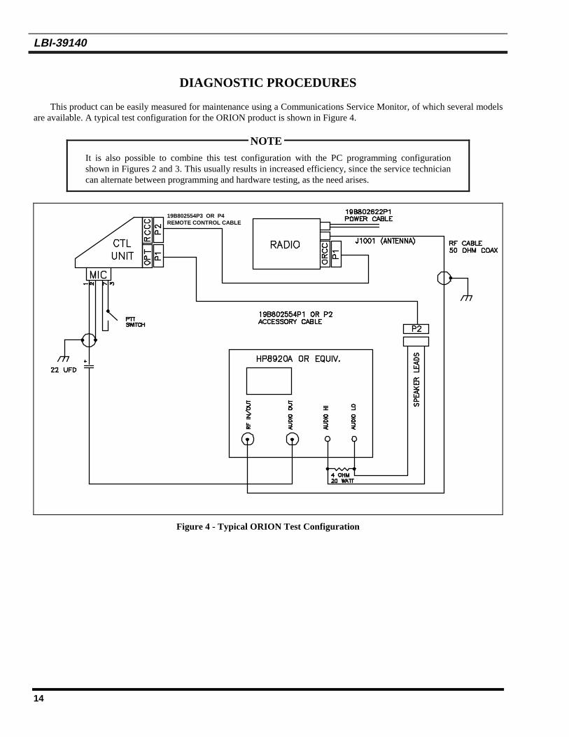
DIAGNOSTIC PROCEDURES
This product can be easily measured for maintenance using a Communications Service Monitor, of which several modelsare available. A typical test configuration for the ORION product is shown in Figure 4.
It is also possible to combine this test configuration with the PC programming configurationshown in Figures 2 and 3. This usually results in increased efficiency, since the service techniciancan alternate between programming and hardware testing, as the need arises.
19B802554P3 OR P4REMOTE CONTROL CABLE
Figure 4 - Typical ORION Test Configuration
NOTE

LBI-39140
15
ADDITIONAL TOOLS REQUIRED:
• RF Power Attenuator (30 dB, 150 watt, for transmitters with RF power beyond capability of the Service Monitor)
• Digital Voltmeter
• Oscilloscope (Optional)
TRANSMITTER
SYMPTOM DIAGNOSTIC PROCEDURE
No RF power output a) Program a conventional system with frequencies given in Table 2 or 3. Use the"EDACS3" PC Programming utility.
b) Check RF Power Tracking Data, using the "MRKMAINT" PC programming utility. Datashould be the same as that shipped with the radio. If fail, re-enter Tracking data usingprocedure given in the "Tracking Data" Section of this manual.
c) Check TP1 on PA board for A+. If not there, check power cable fuse.
d) Key the radio and measure the DC voltage at TP4 (9 Vdc typical, when keyed). If not there,trace TXENABLE signal back to Logic board.
e) Remove P1 from J151 and connect an RF wattmeter to J151. Power should be 1 mW typical.If not, replace Synthesizer board and reload the Modulation Tracking Data. If the correctpower level is there, replace PA board.
Frequency too low/high Adjust the reference oscillator XU201 on the Synthesizer board. If the frequency still not correct,replace the Synthesizer board.
Low or no modulation a) Program a conventional system with frequencies given in Tables 2 or 3. Us the "EDACS3"PC programming utility.
b) Check the Modulation Tracking Data, using the "MRKMAINT" PC programming utility.The data should be the same as that shipped with the radio. If not, re-enter the Tracking Datausing the procedure given in the "Tracking Data" section of this manual.
c) Apply a 1000 mVRMS, 1 kHz audio signal to the microphone connector, Pin 1 (Pin 2 isground reference). Key the radio (make sure the antenna connector is connected to the proper50 ohm load). Check for an audio signal at TP202 on the Synthesizer board. If not there,replace the Synthesizer board and reload the Modulation Tracking Data.

LBI-39140
16
RECEIVER
SYMPTOM DIAGNOSTIC PROCEDURE
Low RF sensitivity a) Program a Conventional System with frequencies given in Tables 2 or 3. Use "EDACS3" PCprogramming utility.
b) Disconnect coaxial cable P2 from J401 on the Synthesizer board. Do not disconnect any othercable.
c) Set the frequency of the RF signal generator to the middle of the split. Apply a standard RFsignal to J401 and measure 12 dB SINAD sensitivity. Sensitivity should be better than 0.29 µV.
d) If correct, replace the PA board.
e) If not, realign the receiver, as instructed in the "ALIGNMENT " section and recheck sensitivityat J401.
f) If correct now, reassemble with the PA module and recheck sensitivity at the antenna connector.If correct, the job is complete.
g) If not correct, substitute a known good Synthesizer board and recheck sensitivity.
h) If still not correct, replace the Logic board. Be sure to perform complete reprogramming on thenew logic board. If correct , replace the Synthesizer board and reload Modulation TrackingData.
High audio distortion a) Program a Conventional System with frequencies given in Tables 2 or 3. Use the "EDACS3"PC programming utility.
b) Apply a standard 1000 µV RF signal (with 1 kHz audio modulation at 3 kHz deviation) at oneof the programmed RF frequencies in the center of the split to J1001. Set the volume control toproduce 15 watts at the 4 ohm speaker load.
c) Measure audio distortion at "VOL HI" output (J1003, Pin 13 referenced to Pin 12). If correct(3% THD), replace IC604 Audio Power Amplifier on the Logic board.
d) If not, realign the receiver according to the alignment procedure. Recheck distortion at thespeaker load or "VOL HI" .
e) If not correct, replace the Logic board. If correct, job is complete.

LBI-39140
17
CONTROL UNIT
SYMPTOM DIAGNOSTIC PROCEDURE
Radio dead atpower-on(display darkand no lightedindicators)
a) Check battery connections and the Red Lead A+ fuse on the Power Cable.
b) Turn unit "OFF", then simultaneously press and hold "EMERGENCY" and "OPTION"buttons, while turning the unit "ON". All indicator lights and all display dots should light.Release the buttons and the display should show the following message:
(C) - 1993
EGE
This indicates that the Control Unit is functioning correctly. If correct, check programming andfeature encryption, using the "EDACS3" PC programming utility.
c) If not correct, measure A+ voltage at the microphone connector, Pin 6 (reference ground at Pin7). If not present, check fuse F601 on the Logic board for A+ on each side of part. Replace ifopen circuited.
d) If the fuse is OK, check the connection of Flex Circuit PC2 with J701 on the Logic board. Ifstill not present, reconnect, making sure side tabs are locked. Recheck microphone connectorPin 6 for A+.
e) If A+ is present, Check programming and feature encryption, using "EDACS3" PCprogramming utility. If symptom persists, substitute a known good Logic board and reprogram.
f) If no A+ is at the microphone, Pin 7, check for A+ on the Logic board, J704, Pin 3. If notthere, check the J704/J1004 connection. If still not there, replace the PA module. If there,replace the Logic board.
Display lights, thengoes dead
a) Turn unit "OFF", then simultaneously press and hold the "EMERGENCY" and "OPTION"buttons, while turning the unit "ON". All indicator lights and all display dots should light. Releasethe buttons and the display should show the following message:
(C) - 1993
EGE
This indicates that the Control Unit is functioning correctly. If OK, check programming andfeature encryption, using "EDACS3" PC programming utility.
b) If OK, check connection of Flex Circuit PC2 with J701 on the Logic board. If not OK, reconnect,making sure side tabs are locked.

LBI-39140
18
GENERAL
SYMPTOM DIAGNOSTIC PROCEDURE
Any Hardwaremalfunction
Printed Wire Board substitution is a valid technique for service and repair of the ORION product,since there are only a few circuit boards in the product:
1) RF Power Amplifier2) Logic/IF/Audio3) Synthesizer/Exciter/RX Front End4) Control Unit Panel Control5) Control Unit Switching6) Control Unit RIA (Remote only)7) DSP (AEGIS only)
The service shop should be equipped with a set of the above circuit boards which can be used forsubstitution. Defective circuit boards can be isolated simply by substituting one at a time. It isrecommended that the Logic board used for substitution be pre-programmed with a conventionalsystem and frequency set given in Tables 2 or 3.
ERROR CODES
This section list all of the ORION radio errors andwarnings. Each error code in the list includes anexplanation of what went wrong and what action to take tocorrect the problem. These error codes are divided intothree different categories:
1. Fatal Operational Error Codes - These are errorsthat are displayed during the radio normal operationor on the radio power-up (Fatal System Errors).These errors will cause the radio to reset.
2. Non-Fatal Operational Error Codes - These areerrors that are displayed during the radio normaloperation or on the radio power-up. The radio willNOT reset.
3. Radio Programming Errors - These are errors thatare displayed on the radio or the programming PCdisplay during radio programming.
All System Groups ORION
System Errors:
Fatal system errors will cause the radio to display anerror message/code and then reset the radio to the startingoperation. The reset condition will remain until the fatalerror(s) is (are) corrected.
Non-Fatal errors are displayed for a short period(about 2 seconds) then normal radio operation willresume.
The errors are displayed on the radio as shown inFigure 6.
Figure 6 - Error Message/Conde Display
messageERR = XXXX
Where XXXX is the error code and the message is one ofthe messages listed as follows.

LBI-39140
19
FATAL ERRORS
ERROR MESSAGE DESCRIPTON
HARDWARE ROM errorsSOFTWARE General software failureTRACKING Tracking data fatal errorNO LOCK Synthesizer not lockingFREQDATA Frequ;ency data fatal errorPERSDATA Personality errors
NON-FATAL ERRORS
ERROR MESSAGE DESCRIPTION
UNKNOWNFEAT ERR Feature encryption errorDSP ERR DSP error
ROM Fatal System Errors
ROM fatal errors may be corrected by cycling the radio power (turn it off then on). When the power cycle does notcorrect the problem the radio must be serviced.
ERROR NAME MESSAGE CODE DESCRIPTION
FATAL_SYS_TRAP HARDWARE 0 Fatal system error trap number.FATAL_NMI_ERROR HARDWARE 1 NMI occurred outside of sleep.FATAL_RAM_ERROR HARDWARE 2 8K RAM test error.FATAL_ROM_CHKSUM HARDWARE 3 32K ROM checksum test error.FATAL_FLSH_CHKSUM HARDWARE 4 Flash checksum test error.FATAL_ASIC_LOAD HARDWARE 10 ASIC driver failed initialization.FATAL_ICP_LOAD HARDWARE 11 ICP driver failed initialization.FATAL_ASP_LOAD HARDWARE 12 ASP driver failed initialization.FATAL_EE_LOAD HARDWARE 13 EEPROM driver failed initialization.FATAL_ICP_PORTNIT HARDWARE 14 ICP digital I/O initialization failed.FATAL_INTOUT_LOAD HARDWARE 15 Standard input/output driver failed initialization.FATAL_INTIN_LOAD HARDWARE 16 Standard input driver failed initialization.FATAL_RADIO_LOAD HARDWARE 17 RADIO driver failed initialization.FATAL_MODEM_LOAD HARDWARE 18 MODEM driver failed initialization.FATAL_EXTIO_LOAD HARDWARE 19 External I/O driver failed initialization.FATAL_SCI_LOAD HARDWARE 20 Serial communication interface driver failed initialization.FATAL _ICP_CHKSUM HARDWARE 21 ICP prom checksum.FATAL_ADI_NOACK HARDWARE 30 ADI did not respond to command.FATAL_ADI_QUNDERFLOW HARDWARE 31 ADI Rx circular queue underflowed.FATAL_LCD_NOACK HARDWARE 40 LCD did not acknowledge message.FATAL_LCD_HARD_FAIL HARDWARE 41 LCD hardware is invalid.FATAL_SCI_NOHEAP HARDWARE 50 Serial communication interface out of heap (RAM memory) space.FATAL_ICP_NOACK HARDWARE 60 ICP did not acknowledge message.FATAL_EXTIO_ICPFAIL HARDWARE 70 ICP failed in a fork.FATAL_RADIO_ASPWRT HARDWARE 80 Radio driver could not write to ASP.FATAL_ROM_NOHEAP HARDWARE 90 Software memory error - ROM task.FATAL_BL_NOHEAP HARDWARE 91 Software memory error - Boot loader.FATAL_BL_SCI_ATTACH HARDWARE 92 Boot loader could not attach to SCI.

LBI-39140
20
Operational Software Fatal System Errors
ERROR NAME MESSAGE CODE DESCRIPTION
RADC_PITD_ERROR TRACKING 200 Personality tracking data error. Re-program the tracking data.RADC_PIHW_ERROR PERSDATA 201 Personality hardware data error. Re-program the personality.RADC_FREQ_ERROR FREQDATA 202 Personality frequency data error. Re-program the personality.RADC_PITD_MALLOC_ERROR SOFTWARE 203 Personality tracking data malloc error. Re-program the tracking data.RADC_PITD_CKSUM_ERROR SOFTWARE 204 Personality tracking data checksum error. Re-program the tracking data.DACS_NO_LOCK NO LOCK 300 Synthesizer did not lock or became unlocked. Check the frequencies in the PC
programmer and re-program the radio personality.DACS_MODEM_FATAL_ERROR SOFTWARE 301 Unable to correctly configure the modem for EDACS operation. Re-program
the personality.DACS_RADC_FAILURE SOFTWARE 302 Power cycle the radio.DACS_MODEM_RXOVR SOFTWARE 304 Hardware Modem overflow. Power cycle the radio.DACS_MODEM_RXAVR SOFTWARE 305 Power cycle the radio.CONV_RADC_ERROR SOFTWARE 400 Error calling RADC function. Power cycle the radio.CONV_NOLOCK_ERROR NO LOCK 401 Synthesizer became unlocked. check the frequencies in the PC programmer
and re-program the radio personality.CONV_PUT_UIMSG_ERROR SOFTWARE 402 UI message buffer not enabled. Power cycle the radio.CONV_MODEM_RXOVR SOFTWARE 403 Conventional DIGV modem overflow.CONV_MODEM_RXAVR SOFTWARE 404 Conventional DIGV modem underflow.CONV_MODEM_FATAL_ERROR SOFTWARE 405 Unable to correctly configure the modem for conventional DIGV operation.CONV_PERS_ERROR PERSDATA 407 Conventional personality error.PI_NOPERS_ERROR PERSDATA 500 Personality data is not present. Program the personality.PI_CRC_ERROR PERSDATA 501 Flash personality CRC did not match EEPROM. Re-program the personality.PI_DESC_CRC_ERROR PERSDATA 502 Crucial personality data has incorrect CRC. Re-program the personality.PI_MALLOC_ERROR SOFTWARE 503 Could not allocate memory to store crucial personality data.UI_FATAL_DEVICE_ERROR PERSDATA 600 Input/Output device error.UI_FATAL_SWTO_MALLOC_ERROR
SOFTWARE 601 Software memory error.
UI_FATAL_SWTO_MAX_ERROR SOFTWARE 602 Software error, power cycle the radio.UI_FATAL_WINDOW_MAX_ERROR
SOFTWARE 603 Too many open windows.
UI_FATAL_WINDOW_MALLOC_ERROR
SOFTWARE 604 Software memory error.
UI_FATAL_MESSAGE_INVPARM SOFTWARE 605 Invalid parameter to UI_PUT_MESSAGE(). software error, report how errorwas encountered.
UI_FATAL_RI_MSGBUF_FULL SOFTWARE 606 UI Task message buffer full error. Software error, report how error wasencountered.
UI_FATAL_RISYS_MSGBUF_FULL SOFTWARE 607 Radio Interface System (EDACS/CONV) task message buffer full.UI_FATAL_CI_MSGBUF_FULL SOFTWARE 608 CI Task message buffer full.UI_FATAL_DEVICE_NOTSUPPORTED
PERSDATA 609 I/O device type (from personality) not supported.
UI_FATAL_AUXIO_MALLOC_ERROR
SOFTWARE 610 Software memory error.
UI_FATAL_NET_DEVICE_ERROR SOFTWARE 611 Network I/O device error.UI_FATAL_INVALID_CUID SOFTWARE 612 CU ID is invalid or CU not connected. Insure that CU ID is CUA and DUAL
is disabled in personality.UI_FATAL_NO TONE_DATA SOFTWARE 613 No tone data is available in personality.UI_FATAL_UIIO_MSGBUF_FULL SOFTWARE 614 U1 I/O BBOS message buffer full.AEGIS_ADI_OVERFLOW SOFTWARE 801 ADI Transmit event not serviced in time and buffer has overflown.AEGIS_RXBUF_MALLOC_ERROR SOFTWARE 802 No memory available.AEGIS_KEYLOAD_MALLOC_ERROR
SOFTWARE 803 No Keyloader table memory available.
AEGIS_KEYLOAD_ERROR SOFTWARE 804 General Keyload error has occurred.AEGIS_DATAMEM_MALLOC_ERROR
SOFTWARE 805 No memory is allocated for data.
AEGIS_KEYLOAD_NOTABL SOFTWARE 806 No key table was found in eeprom.

LBI-39140
21
Operational Software Non-Fatal System Errors
ERROR NAME MESSAGE CODE DESCRIPTION
PIFEAT_SNR_ERROR FEAT ERR 550 Feature encryption - Can not read radio ROM serial number.PIFEAT_READ_ERROR FEAT ERR 551 Personality feature encryption read failure or data not available.PIFEAT_CRC_ERROR FEAT ERR 552 Decryption failure. Personality feature encryption CRC failure.RI_DSPDOWN_NOATTEMPT DSP ERR 850 DSP not foundAEGIS_ADIDOWN_NOTFOUND
DSP ERR 851 DSP file not found.
AEGIS_ADIDOWN_CRCFAIL DSP ERR 852 DSP file not found.AEGIS_ADIDOWN_ENCERR DSP ERR 853 Radio feature encryption does not match DSP file.AEGIS_ADIDOWN_PMFAIL DSP ERR 854 DSP file is corrupted or hardware failure. RE-program radio or power cycle the
radio.AEGIS_ADIDOWN_DMFAIL DSP ERE 855 DSP file is corrupted or hardware failure. Re-program radio or power cycle radio.AEGIS_ADIDOWN_BIOSERR DSP ERR 856 Hardware failure.AEGIS_KEYLOAD_NOBANKS
DSP ERR 860 Personality did not assign banks for the keys.
AEGIS_PVT_NONE FEAT ERR 870 Private is not feature encrypted.
Radio Programming Errors
Programming errors are divided into three categories:1. Protocol Errors - These are errors produced by the low level communication routines.
2. Radio Errors - These are errors that are returned from the radio ROM or operating software.
3. PC Errors - These are errors that are produced by the PC Programming software.
Protocol Errors:
MESSAGE CODE DESCRIPTION
Successful 0 Command was performed successfully.Protocol - Canceled by receiver 5 x328 protocol received a cancel. The radio detected a cancel command.Protocol - Canceled by sender 6 x 328 protocol transmitted cancel. The radio is canceling the read command.Protocol - Terminate transmission 7 x328 protocol received an end of transmission.Protocol - Transmit error 8 x328 protocol could not transmit. Reliable communication can not be established. It could be
the radio or PC hardware problems (programming cable, interface box, or radio hardware).Protocol - Protocol initialization error 9 x328 protocol not initialized or failed to initialize.
Radio Errors:
MESSAGE CODE DESCRIPTION
Radio - Programmed successfully 10 Radio responded with a success. Radio acknowledged successful programming.Radio - Comport configuration failed 11 Radio could not configure its comport (hardware failure).Radio - Flash erase failed 12 Radio failed to erase the flash memory. The radio flash memory part is unusable or it can not
detect the 12 volts power. Check the programming box and cables.Radio - Flash write failed 13 Radio failed in writing to the flash memory. Retry the programming process (hardware
failure).Radio - Flash code CRC did not match 14 Flash code not programmed correctly. CRC did not match. The operating software will not
execute. Re-program the radio.Radio - Canceled by receiver 15 The radio operating software received a cancel command.Radio - Canceled by sender 16Radio - End of transmission received 17 The radio software received or sent an end of transmission.Radio - Transmit error 18 Radio could not transmit the required data. Check all hardware connections and try
programming again.Radio - Invalid command 19 Radio did not understand the received command.Radio - No application code 20 No application code is loaded, the radio con not accept personality commands. Re-program
the operating software (flash code) and re-program the personality.Radio - Application code error 21 The radio application code failed to perform the command.Radio - EEPROM programming error 22 Could not program the radio EEPROM part.Radio - Baud rate has changed 23 The radio acknowledged a successful baud communication baud rate change.
LBI-39140
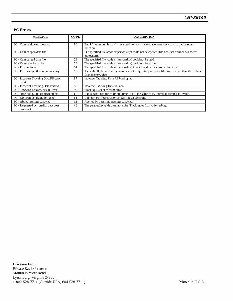
PC Errors
MESSAGE CODE DESCRIPTION
PC - Cannot allocate memory 50 The PC programming software could not allocate adequate memory space to perform thefunction.
PC - Cannot open data file 51 The specified file (code or personality) could not be opened (file does not exist or has accessprotection).
PC - Cannot read data file 52 The specified file (code or personality) could not be read.PC - Cannot write to file 53 The specified file (code or personality) could not be written.PC - File not found 54 The specified file (code or personality) in not found in the current directory.PC - File is larger than radio memory 55 The radio flash part size is unknown or the operating software file size is larger than the radio's
flash memory size.PC - Incorrect Tracking Data RF band
split57 Incorrect Tracking Data RF band split.
PC - Incorrect Tracking Data version 58 Incorrect Tracking Data version.PC - Tracking Data checksum error 59 Tracking Data checksum error.PC- Time-out, radio not responding 60 Radio is not connected or not turned on or the selected PC comport number is invalid.PC - Comport configuration error 61 Comport configuration error, can not set comport.PC - Abort, message canceled 62 Aborted by operator, message canceled.PC - Requested personality data does
not exist63 The personality table does not exist (Tracking or Encryption table).
Ericsson Inc.Private Radio SystemsMountain View RoadLynchburg, Virginia 245021-800-528-7711 (Outside USA, 804-528-7711) Printed in U.S.A.
Ericsson Inc.Private Radio SystemsMountain View RoadLynchburg, Virginia 245021-800-528-7711 (Outside USA, 804-528-7711) Printed in U.S.A.