layher event systems catalogue · headquarters in eibensbach plant 2 in gueglingen quality made by...
TRANSCRIPT

Edition 04.2018Ref. No. 8111.230
Quality management certified accordingto ISO 9001:2008
LAYHER EVENT SYSTEMSCATALOGUE
PA01022393_EN_Katalog_Event_2018.indd 1 09.03.2018 15:27:15
PA
0102
2418
_EN
_Kat
_Eve
nt_2
018.
PA
0102
2418
_EN
_Kat
_Eve
nt_2
018.
PA01022418_EN_Kat_Event_2018.pdf
PA01022418_EN_Kat_Event_2018.pdf

Quality “Made by Layher” 4
More Speed 5
More Safety 5
More Proximity 5
More Simplicity 5
More Future 5
Decision-making aids 6
COMPANYFROM PAGE 4
FROM PAGE 8
Basic components 10
Guardrails and stairways 12
Universal base 14
STAGES AND PODIA FROM PAGE 16
Basic components and guardrails 18
Benches and bucket seats 20
STANDS
Contents
2
PA01022393_EN_Katalog_Event_2018.indd 2 09.03.2018 15:27:23
PA
0102
2418
_EN
_Kat
_Eve
nt_2
018.
PA
0102
2418
_EN
_Kat
_Eve
nt_2
018.
PA01022418_EN_Kat_Event_2018.pdf
PA01022418_EN_Kat_Event_2018.pdf

FOH Systems 24
Roof and wall cladding 26
FROM PAGE 22FOH SYSTEM NOTICE
All dimensions and weights are guideline values. Subject to technical modification.
Steel components are galvanized according to EN ISO 1461 and DASt guideline 022. Connection parts are galvanized according to EN ISO 4042.
Our deliveries shall be made exclusively in accordance with our currently valid General Terms of Sale. These include the following provisions: The place of performance is Gueglingen-Eibensbach. Title to the delivered goods shall be retained until full payment has been made.
Please request the specific instructions for assembly and use when ordering. Protected by copyright. Not to be reproduced, either in whole or in part. Misprints and errors excepted.
Alu Truss Systems 30
Steel Truss Systems 34
FROM PAGE 28TRUSS SYSTEMS
PRODUCT PORTFOLIO
The Layher Product Range – all catalogues at a glance
SpeedyScaf Ref. No. 8102.259Allround Scaffolding Ref. No. 8116.255System-free Accessories Ref. No. 8103.257Protective Systems Ref. No. 8121.257Event Systems Ref. No. 8111.230Access Technology Ref. No. 8118.229
3
PA01022393_EN_Katalog_Event_2018.indd 3 09.03.2018 15:27:26
PA
0102
2418
_EN
_Kat
_Eve
nt_2
018.
PA
0102
2418
_EN
_Kat
_Eve
nt_2
018.
PA01022418_EN_Kat_Event_2018.pdf
PA01022418_EN_Kat_Event_2018.pdf

Headquarters in Eibensbach
Plant 2 in Gueglingen
QUALITY MADE BY LAYHER
HERE IS THE BEATING HEART OF LAYHER.
Quality made by Layher comes from Gueglingen-Eibensbach. Our company
has set down deep local roots since it was established. Right up until today,
development, production, logistics and management are all in one place, where
the conditions are best for achieving quality made by Layher: in Gueglingen-
Eibensbach. The two locations together cover a surface area of 318,000 m².
This includes more than 148,000 m² of covered production and storage areas.
This is where our scaffolding systems are created by highly automated
production. Short distances and short reaction times mean we can adapt
production to suit our customers’ requirements, flexibly and at any time.
MORE POSSIBILITIES. THE SCAFFOLDING SYSTEM.
This brand promise made by Layher is the expression of a brand philosophy that
we’ve been living by for over 70 years. More speed, more safety, more proximity,
more simplicity and more future: values with which we strengthen our customers’
competitiveness in the long term. With our innovative systems and solutions,
we’re working all the time on making scaffolding construction even simpler, even
more economical and, above all, even safer. With comprehensive services, a
permanent range of training courses and an ethos of customer focus, more than
1,700 dedicated Layher employees are creating more possibilities for our
customers every single day. In more than 40 countries all over the world.
MORE INFORMATIONDiscover the world of Layher in its
company film at:
yt-image-en.layher.com
i
Layher
4
PA01022393_EN_Katalog_Event_2018.indd 4 09.03.2018 15:27:34
PA
0102
2418
_EN
_Kat
_Eve
nt_2
018.
PA
0102
2418
_EN
_Kat
_Eve
nt_2
018.
PA01022418_EN_Kat_Event_2018.pdf
PA01022418_EN_Kat_Event_2018.pdf

MORE SPEEDHigh level of material availability, effective delivery service and quick assembly and
dismantling of the scaffolding systems thanks to 100% fitting accuracy.
MORE SAFETYOutstanding quality and precision coupled with a long service life – confirmed internationally
through independent certifications, inspections and approvals. Continuity and long-term
partnership.
MORE PROXIMITYComprehensive personal consultation and close-knit delivery network. Global presence
through our own subsidiaries. Family-owned company that works closely with its customers.
MORE SIMPLICITYEconomical scaffolding systems that have been proven in practice, available with an extensive
product range. Cross-system combinations for versatile use. Rapid decision making thanks to
efficient structures and processes.
MORE FUTUREThanks to permanent product innovations and the improvement of existing parts. By opening
up new areas of business. With an integrated system to ensure high profitability and
retention of investment value. Through an extensive range of training opportunities and
seminars to ensure that customers are always right up-to-date with the latest technical and
commercial developments.
More Possibilities. The Scaffolding System.
5
PA01022393_EN_Katalog_Event_2018.indd 5 09.03.2018 15:27:51
PA
0102
2418
_EN
_Kat
_Eve
nt_2
018.
PA
0102
2418
_EN
_Kat
_Eve
nt_2
018.
PA01022418_EN_Kat_Event_2018.pdf
PA01022418_EN_Kat_Event_2018.pdf

Module EV 86 EV 86+ EV 86Q EV 100Metric*
EV 104
Bay 2.07 x 2.57 m 2.07 x 2.57 m 2.57 x 2.57 m 2.00 x 2.00 m 2.07 x 2.07 m
Deck type Event deck Event deck Event deck Event deck Event deck
Deck size 0.86 x 2.07 m 0.86 x 2.07 m 0.86 x 2.57 m 1.00 x 2.00 m 1.04 x 2.07 m
Decks per bay 3 3 3 2 2
Support element Event transom Event transom Event transom Event transom Event transom
Support element length 2.57 m 2.57 m 2.57 m 2.00 m 2.07 m
Crosspiece support – required – – –
Perm. load capacity 5.0 kN / m² 7.5 kN / m² 5.0 kN / m² 7.5 kN / m² 7.5 kN / m²
LAYHER STAGES Layher stages are just as suitable for use inside halls and marquees as use out -
doors. The components make up a construction kit allowing the building of a
small podium for fashion shows, for a music performance or for a giant concert
stage. The parts are weatherproof, thanks to the use of aluminium, hot-dip
galvanized steel and coated plywood panels. On uneven surfaces, fast and
easy adaptability of the Allround stage to the lie of the land is a particular
advantage. The permissible loading capacity of the podium surface is up to
7.5 kN / m². The height can, depending on the structural strength, be up to
10 m. Meeting of the guidelines for temporary structures with the design
loads as per DIN 4112 is verified by inspection books issued by the competent
authority.
DECISION-MAKING AIDS
LAYHER EVENT SYSTEMS
6
Decision-making aids
i* Further metric components, see catalogue Allround Scaffolding.
PA01022393_EN_Katalog_Event_2018.indd 6 09.03.2018 15:27:53
PA
0102
2418
_EN
_Kat
_Eve
nt_2
018.
PA
0102
2418
_EN
_Kat
_Eve
nt_2
018.
PA01022418_EN_Kat_Event_2018.pdf
PA01022418_EN_Kat_Event_2018.pdf

Seating stand EV 86 x 16 EV 86 x 25 EV 86 x 33 EV 100 x 25Metric*
EV 104 x 25
Step width 0.857 m 0.857 m 0.857 m 1.00 m 1.036 m
Step height 0.166 m 0.25 m 0.333 m 0.25 m 0.25 m
Riser angle [Degree] 11° 16.3° 21.1° 14° 13.6°
Riser angle [%] 19.4 % 29.2 % 38.6 % 24.9 % 24.2 %
Standard dimension 2.57 x 2.07 m 2.57 x 2.07 m 2.57 x 2.07 m 2.00 x 2.00 m 2.07 x 2.07 m
Loose seating possible possible possible recommended recommended
Permanently fitted benches recommended recommended recommended possible possible
LAYHER STANDSThe most important characteristics of Layher seating stands are: sturdy
material, sound workmanship, long service life, rapid assembly at changing
locations, and low transport volume. The individual parts are easy to assemble
and lightweight, so that they can be installed manually. Please refer to our
tables in this connection. Thanks to the modular design, it is possible to adapt
the stand to the local conditions and to plan it in accordance with German
regulations governing public assembly places.
DECISION-MAKING AIDS
More variants upon request
7
PA01022393_EN_Katalog_Event_2018.indd 7 09.03.2018 15:28:03
PA
0102
2418
_EN
_Kat
_Eve
nt_2
018.
PA
0102
2418
_EN
_Kat
_Eve
nt_2
018.
PA01022418_EN_Kat_Event_2018.pdf
PA01022418_EN_Kat_Event_2018.pdf

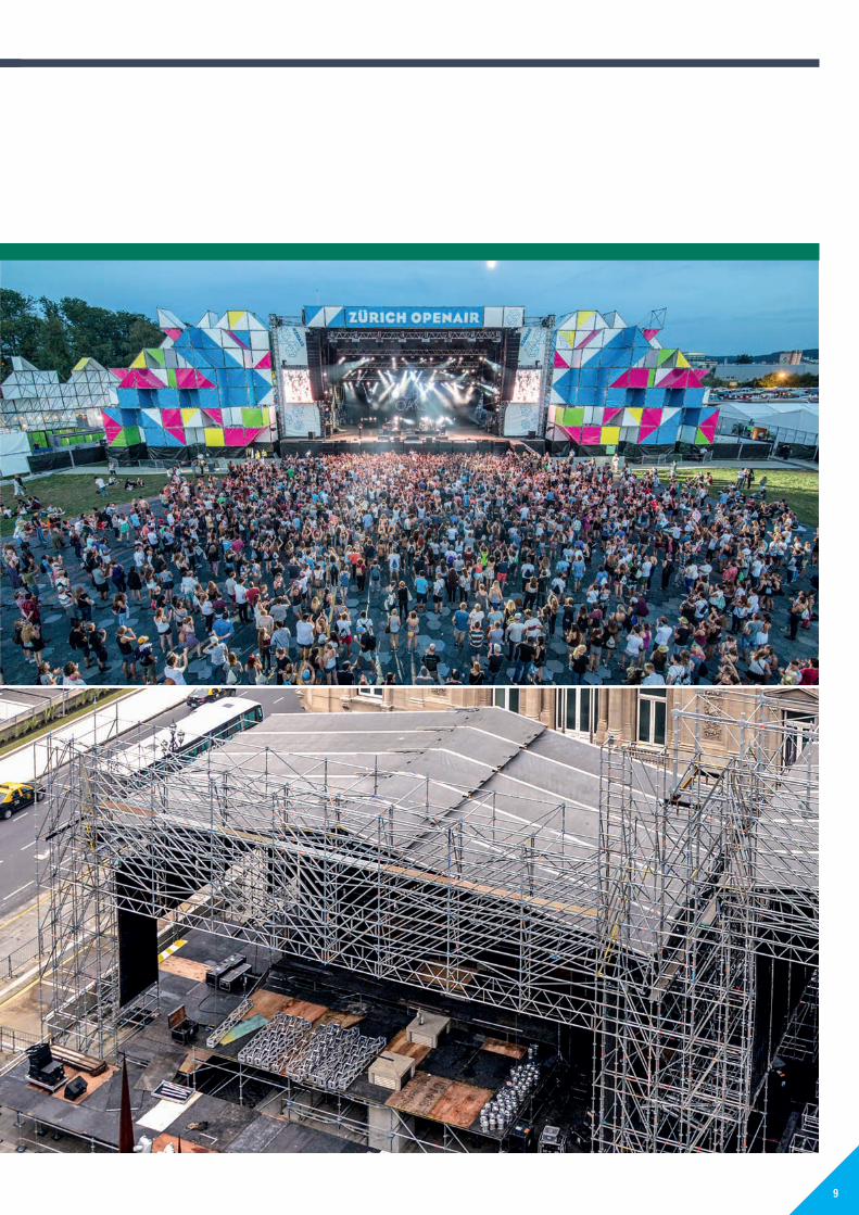
LAYHER STAGES AND PODIA – EASIER, QUICKER AND SAFER BY USING THE MODULAR LAYHER SYSTEM
No compromising on site, fulfils requirements in terms of dimension and
equipment: Layher Event Stages and Podiums.
Layher podiums and stages provide a safe play performance
area that’s exactly what’s needed. Series manufacture and high delivery
readiness are our way to help you cut costs and achieve economic
success; and tailor-made special solutions whenever necessary are our
strengths.
LAYHER EVENT STAGES AND PODIA
Stages and podia
YOUR BENEFITS AT A GLANCE2 Basic unit
Can be expanded with a choice of layouts, standard dimensions
and performing levels.
2 �Expandable
Caters for requirements with a variety of roof and support
systems.
2 Allround base
High load-bearing capacity, rapid assembly and dismantling.
2 Practically-minded design
Strong connector technology, ergonomic handling, low-wear
aluminium parts, corrosion-proof thanks to hot-dip galvanisation,
space-saving storage.
8
PA01022393_EN_Katalog_Event_2018.indd 8 09.03.2018 15:28:14
PA
0102
2418
_EN
_Kat
_Eve
nt_2
018.
PA
0102
2418
_EN
_Kat
_Eve
nt_2
018.
PA01022418_EN_Kat_Event_2018.pdf
PA01022418_EN_Kat_Event_2018.pdf
9
PA01022393_EN_Katalog_Event_2018.indd 9 09.03.2018 15:28:25
PA
0102
2418
_EN
_Kat
_Eve
nt_2
018.
PA
0102
2418
_EN
_Kat
_Eve
nt_2
018.
PA01022418_EN_Kat_Event_2018.pdf
PA01022418_EN_Kat_Event_2018.pdf

The rubber pad 11 must not be used as load-distributing base. It minimizes slippery of the structure.
The Standard�0.67�m 12b and Standard 1.17 m 12c are used for podiums with heights of 0.80 m or 1.30 m and obviate the need for the base collar. The assembly runs faster and ballasting can be placed on the lowest scaffolding level.
The Event decks 1 and 2 up to 2.07 m in length are desi-gned for a load of 7.5 kN / m². The Event deck 2.57 m without transom support can bear 5 kN / m². The removable Plastic corners 8 ensure that the vertical tubes can pass through. The coated plywood board is braced with alu minium rungs.The X-Event decks 2 have plywood boards with rectangular corners. The detachable plastic corners are not removable. Guardrails can be mounted by using posts Ref. No. 5406.000 to the podium.The 18 cm high Event transom 3 of aluminium section with connecting wedge heads of galvanised steel holds the Event decks. The load-bearing capacity of the 2.57 m long Event crosspiece can be increased by reinforcement with the Transom support 4 from 5 kN / m² to 7.5 kN / m².Every side of the Event deck can be beared into the transoms.
The Tension clasp 5 of spring steel connects the Event deck to the Event transom and acts as a lock against lift-off.
A gap-free podium surface is assured by the Square half-coupler 6�to be fitted to the edge of the podium to prevent shifting.
iThe components for the substructure can be found in the catalogue Allround Scaffolding.
The base plate 20 9 and the base plate 40 10 are used especially in stand construction at the lowest stand rows.
iFurther base plates, can be found in the catalogue System-free Accessories.
3
4
5a
7a
8a
11 12a / b /c
8b 8c 10
7b 7c
5b
9
6
Basic components
2
1
10
PA01022393_EN_Katalog_Event_2018.indd 10 09.03.2018 15:28:41
PA
0102
2418
_EN
_Kat
_Eve
nt_2
018.
PA
0102
2418
_EN
_Kat
_Eve
nt_2
018.
PA01022418_EN_Kat_Event_2018.pdf
PA01022418_EN_Kat_Event_2018.pdf

Pos. Description DimensionsL�/�H�x�W�[m]
Weight�approx.�[kg]
PU[pcs.]
Ref. No.
EV 86
EV 86Q
EV 100
EV 104
1 Event�deck�T16aluminium frame, coated plywood, detachable plastic corners
0.86 x 1.04 16.9 10 5402.201 P 20.86 x 2.07 30.2 10 5402.202 W 20.86 x 2.57 36.7 10 5402.204 W 21.00 x 1.00 18.3 10 5402.205 P 21.00 x 2.00 32.5 10 5402.206 W 21.04 x 1.04 19.3 10 5402.208 P 21.04 x 2.07 34.3 10 5402.209 W 2
2 X-Event�deck�T16�as Pos. 1, but with not detachable plastic corners
0.86 x 1.04 16.9 10 5402.211 P 20.86 x 2.07 30.2 10 5402.212 P 20.86 x 2.57 36.7 10 5402.214 P 21.00 x 1.00 18.3 10 5402.215 P 21.00 x 2.00 32.5 10 5402.216 P 21.04 x 1.04 19.3 10 5402.218 P 21.04 x 2.07 34.3 10 5402.219 P 2
3 Event transom 0.86 6.1 60 5400.072 W 21.00 6.4 60 5400.010 W 21.04 6.6 60 5400.020 W 21.71 10.0 60 5400.071 W 22.00 11.4 60 5400.040 W 22.07 12.0 60 5400.050 W 22.57 14.6 60 5400.070 W 2 2
4 Transom supportincreases permissible load on the EV 86+ system
2.57 x 0.50 21.2 40 5400.100 W 2
5a Tension�clasp�T16, for Event deck T16
0.16 2.5 50 v 5403.516 W 2 2 2 2
5b Tension�clasp,for Event deck T1, T4, T7 and T10
0.16 2.6 50 v 5403.514 W 2 2 2 2
6 Square half-coupler 1.4 5403.510 W 2 2 2 2
7a Clamp�T16,�for coupling Event decks, yellow 0.3 50 5403.518 W 2 2 2 2
7b Clamp�T10,�T7,�for coupling Event decks, black 0.4 50 5403.506 W 2 2 2 2
7c Clamp�T4,�T1,�for coupling Event decks, green 0.3 50 5403.502 W 2 2 2 2
8a Plastic�corner,�spare part for Event deck, from YOM 2016
3.5 50 v 5403.519 W 2 2 2 2
8b Plastic�corner,�spare part for Event deck, YOM 2004–2016
3.4 50 v 6494.101 W 2 2 2 2
8c Plastic�corner�incl.�bolt,�spare part for Event deck, YOM 2001–2004
4.5 50 v 6494.100 W 2 2 2 2
9 Base plate 20max. spindle travel 10 cm
0.20 2.3 200 5602.020 W 2 2 2 2
10 Base plate 40max. spindle travel 25 cm
0.40 2.9 200 4001.040 W 2 2 2 2
11 Rubber pad for base platefor slip-reduction on solid grounds like concrete, asphalt, stone or timber, protects sensitive deckings from damages.
0.20 x 0.20 0.4 4000.500 W 2 2 2 2
12a Base�collar,�short 0.17 1.1 250 5601.000 W 2 2 2 2
12b Standard, 0.67 m, with 2 rosettes, without spigot,with integrated base collar
0.67 3.6 200 2604.066 W 2 2 2 2
12c Standard, 1.17 m, with 3 rosettes, without spigot,with integrated base collar
1.17 6.1 28 2604.116 W 2 2 2 2
11
WS = wrench size PU = packaging unit W = available ex works P = delivery time on request V = only available in this packaging unit
PA01022393_EN_Katalog_Event_2018.indd 11 09.03.2018 15:28:41
PA
0102
2418
_EN
_Kat
_Eve
nt_2
018.
PA
0102
2418
_EN
_Kat
_Eve
nt_2
018.
PA01022418_EN_Kat_Event_2018.pdf
PA01022418_EN_Kat_Event_2018.pdf

Side protection of the stage is provided by Handrails 2 or Guardrails with child safety features 3. The stairway stringer 5 fits exactly to the height of the Event decks. Thus it is always as top step. Depending on the podium height, the stairway can be extended with different stairway stringers.
6
7
8
911
10
Podium height: 0.90 mStairway: 2639.003
The artist entry to the stage is via the modular stairway. The construction kit comprises: Stringer for modular stairway,�1,�2�and�3�steps�6, Base�collar�0.26�m�8 and O-ledger 0.90 m 10. If required, stairway guardrails are attached. The bolts needed for guardrail assembly are included with every stairway guardrail. The guardrails are not suitable for public areas.
i
In combination of different stairway stringers, the possibly different stairway dimension must be pointed out. For further information, please see catalogue Allround Scaffolding.
1 2
3
Guardrails and stairways for stages
Riser s = 16.0 cmTread a = 31.8 cmUndercut u = 0.2 cm
4/5
12
PA01022393_EN_Katalog_Event_2018.indd 12 09.03.2018 15:28:56
PA
0102
2418
_EN
_Kat
_Eve
nt_2
018.
PA
0102
2418
_EN
_Kat
_Eve
nt_2
018.
PA01022418_EN_Kat_Event_2018.pdf
PA01022418_EN_Kat_Event_2018.pdf

Pos. Description DimensionsL�/�H�x�W�[m]
Weight�approx.�[kg]
PU[pcs.]
Ref. No.
EV 86
EV 86Q
EV 100
EV 104
1 Guardrail post for podium 1.64 13.8 20 5406.000 W 2 2 2 2
2 Handrail T13handrail height 1.00 m
1.00 7.9 40 5417.100 P 21.04 8.1 40 5417.104 P 22.00 15.0 40 5417.200 P 22.07 15.4 40 5417.207 W 2 22.57 18.7 40 5417.257 P 2 2
3 Guardrail with child safety feature T12guardrail height 1.10 m,connection elements height adjustable for use with Event or scaffolding decks
0.86 18.5 25 5409.086 P 21.00 19.8 25 5409.100 W 21.04 20.0 25 5409.104 W 21.57 25.8 25 5409.157 W 22.00 30.5 25 5409.200 W 22.07 30.8 25 5409.207 W 2 22.57 35.8 25 5409.257 W 2 2
4 Stairway guardrail 750 with child safety featurefor stairway stringer Pos. 5
1.00 x 1.57 22.0 25 2616.106 W 2 2 2 2
5 U-Stairway stringer 750 with half-couplerwith 5 steps
1.00 x 1.57 28.0 20 2639.003 W 2 2 2 2
6 Stringer for modular stairway 1-step 0.30 2.4 50 5407.001 W 2 2 2 22-step 0.60 5.5 50 5407.002 W 2 2 2 23-step 0.90 8.0 20 5407.003 W 2 2 2 2
7 Guardrail for modular stairway 1-step 0.30 x 1.10 6.5 40 5407.011 W 2 2 2 22-step 0.60 x 1.10 14.0 25 5407.012 W 2 2 2 23-step 0.90 x 1.10 16.0 25 5407.013 W 2 2 2 2
8 Base�collar�for�modular�stairway,�0.26 mwith spigot
0.26 2.0 450 5407.021 W 2 2 2 2
9 Standard�for�modular�stairway,�0.59 mwith spigot
0.59 3.1 250 5407.022 W 2 2 2 2
10 O-ledger�LW,�0.90 m 0.90 3.4 50 2601.090 W 2 2 2 2
11 Lift-off�preventer, 0.29 m, with bolt 0.29 0.4 500 5407.030 W 2 2 2 2
For�further�stairways�and�access�assemblies,�see�Allround�Scaffolding�System�Catalogue.
13
WS = wrench size PU = packaging unit W = available ex works P = delivery time on request V = only available in this packaging unit
PA01022393_EN_Katalog_Event_2018.indd 13 09.03.2018 15:28:56
PA
0102
2418
_EN
_Kat
_Eve
nt_2
018.
PA
0102
2418
_EN
_Kat
_Eve
nt_2
018.
PA01022418_EN_Kat_Event_2018.pdf
PA01022418_EN_Kat_Event_2018.pdf
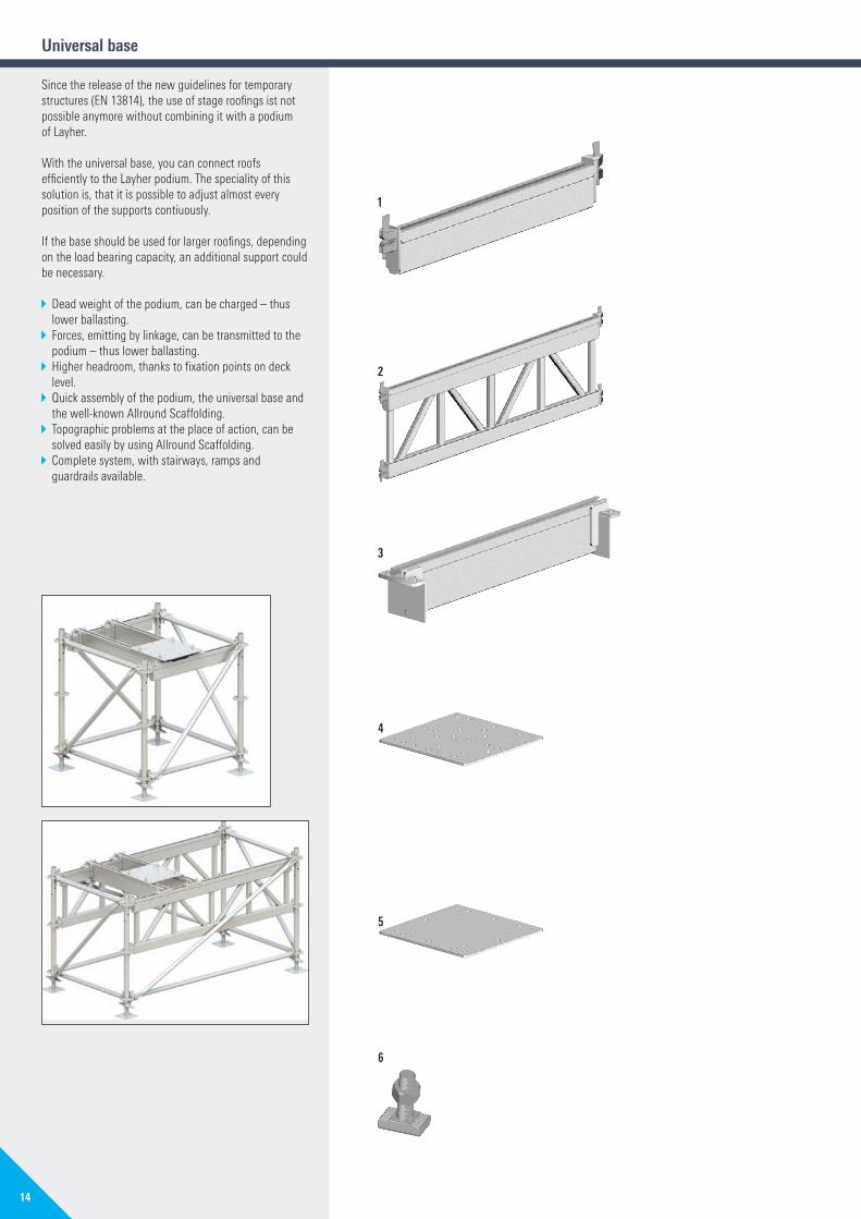
Universal base
Since the release of the new guidelines for temporary structures (EN 13814), the use of stage roofings ist not possible anymore without combining it with a podium of Layher.
With the universal base, you can connect roofs efficiently to the Layher podium. The speciality of this solution is, that it is possible to adjust almost every position of the supports contiuously.
If the base should be used for larger roofings, depending on the load bearing capacity, an additional support could be necessary.
2 Dead weight of the podium, can be charged – thus lower ballasting.
2 Forces, emitting by linkage, can be transmitted to the podium – thus lower ballasting.
2 Higher headroom, thanks to fixation points on deck level.
2 Quick assembly of the podium, the universal base and the well-known Allround Scaffolding.
2 Topographic problems at the place of action, can be solved easily by using Allround Scaffolding.
2 Complete system, with stairways, ramps and guardrails available.
1
2
3
4
5
6
14
PA01022393_EN_Katalog_Event_2018.indd 14 09.03.2018 15:29:01
PA
0102
2418
_EN
_Kat
_Eve
nt_2
018.
PA
0102
2418
_EN
_Kat
_Eve
nt_2
018.
PA01022418_EN_Kat_Event_2018.pdf
PA01022418_EN_Kat_Event_2018.pdf

Pos. Description DimensionsL�/�H�x�W�[m]
Weight�approx.�[kg]
PU[pcs.]
Ref. No.
EV 86
EV 100
EV 104
1 Base beamsteel, hot-dip galvanized
0.86 13.0 10 5431.086 P 21.00 15.5 10 5431.100 P 21.04 16.1 10 5431.104 P 22.00 32.5 10 5431.200 P 22.07 33.7 10 5431.207 P 2 2
2 Base beamsteel, hot-dip galvanized
0.86 x 0.50 38.2 10 5432.086 P 21.00 x 0.50 38.5 10 5432.100 P 21.04 x 0.50 39.1 10 5432.104 P 22.00 x 0.50 76.0 10 5432.200 P 22.07 x 0.50 76.7 10 5432.207 P 2 2
3 Truss-Transomsteel, hot-dip galvanized
0.86 27.8 8 5433.086 P 21.00 28.9 8 5433.100 P 21.04 29.0 8 5433.104 P 22.00 47.3 20 5433.200 P 22.07 48.6 8 5433.207 P 2 2
4 Base plate type 1steel, hot-dip galvanized,for H30V and H40V support with 31 drillings
0.41 x 0.41 25.0 10 5434.003 P 2 2 2
5 Base plate type 2steel, hot-dip galvanized,for H30V and H40V supportwith 16 drillings
0.41 x 0.41 25.0 10 5434.002 P 2 2 2
6 Special�bolt,�with nutHZS 53 x 34
M16 x 60 2.0 12 v 5434.012 W 2 2 2
15
WS = wrench size PU = packaging unit W = available ex works P = delivery time on request V = only available in this packaging unit
PA01022393_EN_Katalog_Event_2018.indd 15 09.03.2018 15:29:01
PA
0102
2418
_EN
_Kat
_Eve
nt_2
018.
PA
0102
2418
_EN
_Kat
_Eve
nt_2
018.
PA01022418_EN_Kat_Event_2018.pdf
PA01022418_EN_Kat_Event_2018.pdf

Stands
FOR GETTING THE CROWD’S MONEY’S WORTH
No restrictions on comfort, no limits on dimensions and equipment,
no concessions to the location: Layher stands are always an excellent
“observation point”, just as required.
The Layher Event-System: Stands for sitting, all over the world and
meeting client requirements. Series manufacture and high delivery
readiness are our way to help you cut costs and achieve economic
success; and tailor-made special solutions whenever necessary are
our strengths.
The whole Layher Event-System bases on the proven Allround Scaffolding
System. Thus makes investions even more economical, because the
material can be used for lots of different kinds of use.
LAYHER EVENT STANDS
YOUR BENEFITS AT A GLANCE2 Standard solutions
Series material, rapid availability.
2 Substructure Allround
High load-bearing capacity, rapid and flexible erection and
dismantling, choice of accessories.
2 Handy components
Easy to transport and store, palletizable.
2 Special design
for individualized problem solutions.
16
PA01022393_EN_Katalog_Event_2018.indd 16 09.03.2018 15:29:10
PA
0102
2418
_EN
_Kat
_Eve
nt_2
018.
PA
0102
2418
_EN
_Kat
_Eve
nt_2
018.
PA01022418_EN_Kat_Event_2018.pdf
PA01022418_EN_Kat_Event_2018.pdf

17
PA01022393_EN_Katalog_Event_2018.indd 17 09.03.2018 15:29:20
PA
0102
2418
_EN
_Kat
_Eve
nt_2
018.
PA
0102
2418
_EN
_Kat
_Eve
nt_2
018.
PA01022418_EN_Kat_Event_2018.pdf
PA01022418_EN_Kat_Event_2018.pdf
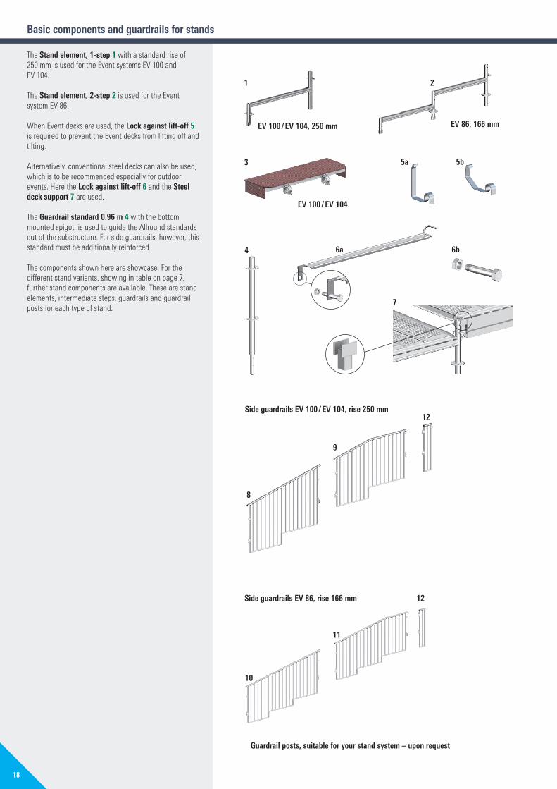
The Stand�element,�1-step�1 with a standard rise of 250 mm is used for the Event systems EV 100 and EV 104.
The Stand�element,�2-step�2 is used for the Event system EV 86.
When Event decks are used, the Lock against lift-off 5 is required to prevent the Event decks from lifting off and tilting.
Alternatively, conventional steel decks can also be used, which is to be recommended especially for outdoor events. Here the Lock against lift-off 6 and the Steel deck support 7 are used.
The Guardrail�standard�0.96�m�4 with the bottom mounted spigot, is used to guide the Allround standards out of the substructure. For side guardrails, however, this standard must be additionally reinforced.
The components shown here are showcase. For the different stand variants, showing in table on page 7, further stand components are available. These are stand elements, intermediate steps, guardrails and guardrail posts for each type of stand.
Side�guardrails�EV 86,�rise�166 mm
Guardrail�posts,�suitable�for�your�stand�system�–�upon�request
11
12
10
Basic components and guardrails for stands
EV 100�/�EV 104,�250 mm
1
EV 100�/�EV 104
3
4
7
5a 5b
EV 86,�166 mm
2
Side�guardrails�EV 100�/�EV 104,�rise�250 mm
9
12
8
6b6a
18
PA01022393_EN_Katalog_Event_2018.indd 18 09.03.2018 15:29:26
PA
0102
2418
_EN
_Kat
_Eve
nt_2
018.
PA
0102
2418
_EN
_Kat
_Eve
nt_2
018.
PA01022418_EN_Kat_Event_2018.pdf
PA01022418_EN_Kat_Event_2018.pdf

Pos. Description DimensionsL�/�H�x�W�[m]
Weight�approx.�[kg]
PU[pcs.]
Ref. No.
EV 86
EV 86Q
EV 100
EV 104
1 Stand element1-step
1.00 x 0.25 6.6 40 5401.010 W 21.04 x 0.25 6.7 40 5401.020 W 2
2 Stand element2-step
1.71 x 0.33 10.5 30 5401.030 W 2 2
3 Intermediate step0.30 x 0.12 x L, with 2 half couplers
L = 1.00 8.4 12 5402.110 P 2 2L = 1.25 10.5 24 5402.130 P 2 2
4 Guardrail�standard,�0.96 mwith bottom mounted spigot and 2 cutaway rosettes
0.96 5.5 28 5405.045 W 2 2 2 2
5a Lift-off preventer for Event deck T1, T4, T7 and T10
0.10 0.04 5403.501 W 2 2 2 2
5b Lift-off�preventer�T16 for Event deck
2.0 50 v 5403.517 W 2 2 2 2
6a Lift-off preventer for steel decks 0.86 1.6 5403.007 W 2 2
6b Bolt�M10�x�70�with nut 3.5 50 v 5403.009 W 2 2
7 Steel deck support 0.10 0.4 5403.006 W 2 2
8 Side guardrail T122-step
2.00 x 1.10 32.2 28 5410.201 P 22.07 x 1.10 32.5 25 5410.204 W 2
9 Side end guardrail T122-step
2.00 x 1.10 30.4 25 5410.202 P 22.07 x 1.10 30.7 25 5410.206 P 2
10 Side guardrail T123-step
2.57 x 1.10 35.2 25 5410.301 P 2 2
11 Side end guardrail T123-step
2.57 x 1.10 34.3 25 5410.302 P 2 2
12 Corner�guardrail,�top steel
1.10 x 0.28 11.2 40 5410.303 W 2 2 2 2
19
WS = wrench size PU = packaging unit W = available ex works P = delivery time on request V = only available in this packaging unit
PA01022393_EN_Katalog_Event_2018.indd 19 09.03.2018 15:29:26
PA
0102
2418
_EN
_Kat
_Eve
nt_2
018.
PA
0102
2418
_EN
_Kat
_Eve
nt_2
018.
PA01022418_EN_Kat_Event_2018.pdf
PA01022418_EN_Kat_Event_2018.pdf

You can choose the seating to suit the application, but also to suit your specific conditions. There is a choice of benches, bucket seats and tip-up seats.
The Bench 1 is 0.30 m wide and comprises anodised aluminium stiles and smooth-coated plywood.
Benches are secured with wedges: Short wedges 6 are needed at the edge of the stand. Bench ends 2 are fitted at the access to the stand.
Novanta bucket seats 3a can be fastened to the benches. We recommend benches with predrilled holes here. The standard Novanta bucket seats are dark blue, UV-protected and flame-retardant.
The assembly material comprises per seat:2 bolts with square neck2 washers2 nuts1 plug, left1 plug, rightNumber plate without lettering, white.
Alternatively, your own chairs can be placed on the Event stand EV 100 & EV 104.
For the first row of seat you need the Seat support with rosette 8.
Different tip-up seats 9 can be mounted to the existing stand structure using the suitable frames 10 and adapters 11.
Benches and bucket seats
1/2
11a 11b 11c 11d
9
10
5/6
7
84
3a
3d3c3b
3e
20
PA01022393_EN_Katalog_Event_2018.indd 20 09.03.2018 15:29:35
PA
0102
2418
_EN
_Kat
_Eve
nt_2
018.
PA
0102
2418
_EN
_Kat
_Eve
nt_2
018.
PA01022418_EN_Kat_Event_2018.pdf
PA01022418_EN_Kat_Event_2018.pdf

Pos. Description DimensionsL�/�H�x�W�[m]
Weight�approx.�[kg]
PU[pcs.]
Ref. No.
EV 86
EV 86Q
EV 100
EV 104
1 Benchanodised aluminium, coated plywood
1.57 x 0.30 7.2 60 5623.157 P 2 22.00 x 0.30 9.4 60 5623.200 W 22.07 x 0.30 9.5 60 5623.207 W 2 22.57 x 0.30 11.7 60 5623.257 W 2
2 Bench endanodised aluminium, coated plywood
0.06 x 0.30 0.5 100 5624.000 W 2 2 2 2
3a Novanta�bucket�seat, blueUV-protected and flame-retardant
0.40 x 0.43 1.7 120 5408.021 W 2 2 2 2
3b3c
Plug, left, bluePlug, right, blue
0.2 20 v 5408.026 W 2 2 2 20.2 20 v 5408.027 W 2 2 2 2
3d Number�plate,�without lettering, white 0.2 20 v 5408.025 W 2 2 2 2
3e Assembly-Set for 20 bucket seatsexisting of 40 bolts M8 x 40, 40 nuts and 40 washers
1.2 100 5408.007 W
4 Bench,�with holesfor Novanta bucket seats
1.57 x 0.30 7.2 60 5408.157 P 2 22.07 x 0.30 9.5 60 5408.207 W 2 22.57 x 0.30 11.7 60 5408.257 W 2
5 Allround�wedge, steel, for securing bench
complete with rivetwithout rivet
0.14 3.3 25 v 6494.916 2 2 213.0 100 v 6494.918 W 2 2 2
6 Allround�wedge,�short, 90 mmwithout holes, for securing bench at edge of stand
0.09 1.0 10 v 6494.965 W 2 2 2
7 Bench adaptor for rise 16.7 cmfor rise 25.0 cm
0.42 3.7 350 5406.010 W 2 20.34 3.4 400 5406.015 W 2 2
8 Seat support with rosettefor bottom rows
0.34 4.0 300 5619.000 P 2 2 2 2
9 Tip-up seatUV-protected and flame-retardant available in 10 different colours
0.48 x 0.42 3.2 80 80 5515.001 W 2 2 2 2
10 Aluminium frame for tip-up seatssuitable for all inclinations
1.50 x 0.43 7.4 30 5516.150 P 21.57 x 0.43 7.6 30 5516.157 P 2 2 22.00 x 0.43 9.4 30 5516.200 P 22.07 x 0.43 9.7 30 5516.207 W 2 22.50 x 0.43 11.6 30 5516.250 P 22.57 x 0.43 11.8 30 5516.257 P 2
11a Adaptor with spigot 0.17 x 0.10 2.8 150 5521.001 W 2 2 2 2
11b Adaptor with rosettefor lowest stand row
0.26 x 0.10 3.5 150 5521.002 P 2 2 2 2
11c Standard 0.92 m with adaptor for guardrail mounting
0.92 7.8 50 5521.003 P 2 2 2 2
11d Standard 1.18 m with adaptor for guardrail mounting at the lowest stand row
1.18 7.9 50 5521.004 P 2 2 2 2
21
WS = wrench size PU = packaging unit W = available ex works P = delivery time on request V = only available in this packaging unit
PA01022393_EN_Katalog_Event_2018.indd 21 09.03.2018 15:29:35
PA
0102
2418
_EN
_Kat
_Eve
nt_2
018.
PA
0102
2418
_EN
_Kat
_Eve
nt_2
018.
PA01022418_EN_Kat_Event_2018.pdf
PA01022418_EN_Kat_Event_2018.pdf

QUICK AND CLEAN. FLEXIBLE FRONT-OF-HOUSE SOLUTIONS FROM LAYHER
The Layher FOH Tower Kit System provides you with the right solution
for your Front-Of-House applications. To meet the most frequently
encountered requirements, a total of 12 FOH Tower complete KITs are
available.
ONE SYSTEM – MANY VARIANTS
The Kit System and Layher’s flexible Allround equipment offers
an impressive variability.
Whether it’s a 2 or 3 bay width, with or without a projecting roof and
entrance, with 1, 2 or 3 storeys. The Layher FOH Tower Kit System means
more possibilities. Typical for Layher!
LAYHER FOH TOWER KIT SYSTEM
FOH�System,�Roof and wall cladding
YOUR BENEFITS AT A GLANCE2 Quick and easy assembly thanks to optimum use of material.
2 Neat and practically-minded design down to the last detail.
2 Each of the maximum of three levels is without a hindering
central support.
2 Complete enclosure using keder tarpaulins.
2 Very few special parts.
2 Two inspection books available: 4.14 m x 4.14 m (4 x 4) and
6.21 m x 4.14 m (6 x 4).
22
PA01022393_EN_Katalog_Event_2018.indd 22 09.03.2018 15:29:41
PA
0102
2418
_EN
_Kat
_Eve
nt_2
018.
PA
0102
2418
_EN
_Kat
_Eve
nt_2
018.
PA01022418_EN_Kat_Event_2018.pdf
PA01022418_EN_Kat_Event_2018.pdf

23
PA01022393_EN_Katalog_Event_2018.indd 23 09.03.2018 15:29:56
PA
0102
2418
_EN
_Kat
_Eve
nt_2
018.
PA
0102
2418
_EN
_Kat
_Eve
nt_2
018.
PA01022418_EN_Kat_Event_2018.pdf
PA01022418_EN_Kat_Event_2018.pdf

The Layher FOH Towers are of modular design in a kit system. To add a further storey to your FOH tower, it’s only neccessary to adjust the number of parts, but not their type. The optionally available projecting roofs and the optional entrance steps can be easily mounted if required.
For all illustrated variants of the FOH tower, a test book can be created. The construction complies with DIN EN 13814, which reflects the current state of the art. The Layher FOH tower is available in the well-known Layher grid dimensions and in metric dimensions.
The wall coverings (rear wall and side walls) are available as a separate kit for all FOH towers variants. These consist of: keder rail holders, keder rails 2000, keder tarpaulins and gable tarpaulins.
1
4
2
5
7
8
9
3
6
FOH System
24
PA01022393_EN_Katalog_Event_2018.indd 24 09.03.2018 15:30:05
PA
0102
2418
_EN
_Kat
_Eve
nt_2
018.
PA
0102
2418
_EN
_Kat
_Eve
nt_2
018.
PA01022418_EN_Kat_Event_2018.pdf
PA01022418_EN_Kat_Event_2018.pdf

Pos. Description DimensionsL�/�H�x�W�[m]
Weight�approx.�[kg]
PU[pcs.]
Ref. No.
1a FOH Tower with 1 storey including roof tarpaulins
4.00 x 4.00 5060.050
Wall covering for FOH tower 1a 5060.070
1b FOH Tower with 1 storey including roof tarpaulins
4.14 x 4.14 5060.450
Wall covering for FOH tower 1b 5060.470
2a FOH Tower with 2 storeys including roof tarpaulins
4.00 x 4.00 5060.051
Wall covering for FOH tower 2a 5060.071
2b FOH Tower with 2 storeys including roof tarpaulins
4.14 x 4.14 5060.451
Wall covering for FOH tower 2b 5060.471
3a FOH Tower with 3 storeys including roof tarpaulins
4.00 x 4.00 5060.052
Wall covering for FOH tower 3a 5060.072
3b FOH Towerwith 3 storeys including roof tarpaulins 4.14 x 4.14 5060.452
Wall covering for FOH tower 3b 5060.472
4a FOH Tower with 1 storey including roof tarpaulins
6.00 x 4.00 5060.060
Wall covering for FOH tower 4a 5060.080
4b FOH Tower with 1 storey including roof tarpaulins
6.21 x 4.14 5060.460
Wall covering for FOH tower 4b 5060.480
5a FOH Tower with 2 storeys including roof tarpaulins
6.00 x 4.00 5060.061
Wall covering for FOH tower 5a 5060.0815b FOH Tower
with 2 storeys including roof tarpaulins6.21 x 4.14 5060.461
Wall covering for FOH tower 5b 5060.481
6a FOH Tower with 3 storeys including roof tarpaulins
6.00 x 4.00 5060.062
Wall covering for FOH tower 6a 5060.082
6b FOH Tower with 3 storeys including roof tarpaulins
6.21 x 4.14 5060.462
Wall covering for FOH tower 6b 5060.482
7 FOH entrance 2.00 5060.057
2.07 5060.457
8 FOH projecting roof for 2 bays including tarpaulin
4.00 5060.056
4.14 5060.456
9 FOH projecting roof for 3 bays including tarpaulin
6.00 5060.066
6.21 5060.466
10 Support for reaching an inspection bookfor all illustrated variants of the FOH tower
3.2 5400.150 P
25
WS = wrench size PU = packaging unit W = available ex works P = delivery time on request V = only available in this packaging unit
PA01022393_EN_Katalog_Event_2018.indd 25 09.03.2018 15:30:05
PA
0102
2418
_EN
_Kat
_Eve
nt_2
018.
PA
0102
2418
_EN
_Kat
_Eve
nt_2
018.
PA01022418_EN_Kat_Event_2018.pdf
PA01022418_EN_Kat_Event_2018.pdf

1
2
4
5/6
Assembly�Pos.�4�+�5
3
Roof and wall cladding
The proven keder rail 2000 7. Known for its low weight. Ideal for lightweight applications, particularly for wall coverings and scaffolding covers.
The keder rail 3000 8 – very strong yet light. It is perfectly suited for medium spans, as found for example in FOH and directing towers or in technical equipment and storage areas. The keder rail K3000 can also be used as a wall keder rail over large spans.
The keder rail 9000 9 is suitable as a heavy-duty marquee section for large and very large spans. Roofs and side coverings for large open-air stages can be constructed with this section, in addition to massive roofs for stands.
12
13
7
8
9
10 11 14
FOH System
26
PA01022393_EN_Katalog_Event_2018.indd 26 09.03.2018 15:30:15
PA
0102
2418
_EN
_Kat
_Eve
nt_2
018.
PA
0102
2418
_EN
_Kat
_Eve
nt_2
018.
PA01022418_EN_Kat_Event_2018.pdf
PA01022418_EN_Kat_Event_2018.pdf

Pos. Description DimensionsL�/�H�x�W�[m]
Weight�approx.�[kg]
PU[pcs.]
Ref. No.
EV 86
EV 100
EV 104
1 FOH beam 4.00 38.1 20 5573.010 W 2
4.14 38.6 20 5573.011 W 2
2 Event�access�deck�T16with aluminium hatch
0.86 x 2.07 33.9 5402.221 P 2
1.00 x 2.00 36.3 10 5402.222 P 2
1.04 x 2.07 38.0 10 5402.223 P 2
3 Single�step�ladder,�with hook10-stepsfor storey height 2.50 m
2.70 x 0.45 7.7 10 5573.021 W 2 2
4 FOH rope holder set4 partsfor connection of the ballast bays
2.7 100 5573.002 W 2 2
5 Rope fastenerfor ballast bays
1.22 1.3 10 5573.005 P 2 2
6 Rope fastenerfor roof stiffening
as HD 4.00 x 4.00 m 5.57 7.5 10 5573.003 P 2 2as HD 4.14 x 4.14 m 5.77 7.6 10 5573.004 P 2 2
Pos. Description DimensionsL�/�H�x�W�[m]
Weight�approx.�[kg]
PU[pcs.]
Ref. No.
7 Aluminium keder rail 2000 for side tarpaulins
2.50 3.8 100 4201.250 W
8 Aluminium keder rail 3000for roof tarpaulins
2.00 6.1 20 5574.200 P3.00 9.2 20 5574.300 P4.00 12.2 20 5574.400 P5.00 15.3 20 5574.500 P6.00 18.3 50 5574.600 W
9 Aluminium keder rail 9000 5.00 54.8 10 5577.500 P6.00 65.8 10 5577.600 P9.00 98.7 10 5577.900 P
10 Keder�rail�holder,�rotatable, incl. 2 captive bolts 0.9 500 5573.000 W11 Keder�rail�holder,�rotatable, with half-coupler, incl. 2 captive bolts 1.0 500 5573.006 W
12 Hinged attachment for Event roof 3.4 100 5573.001 W13 Half-coupler, with plate 0.20 x 0.10 2.1 100 5573.030 P
14 Captive bolt for keder rail M12 x 40, with nut,for Pos. 12 and 13
5.0 50 v 4206.001 W
27
WS = wrench size PU = packaging unit W = available ex works P = delivery time on request V = only available in this packaging unit
PA01022393_EN_Katalog_Event_2018.indd 27 09.03.2018 15:30:16
PA
0102
2418
_EN
_Kat
_Eve
nt_2
018.
PA
0102
2418
_EN
_Kat
_Eve
nt_2
018.
PA01022418_EN_Kat_Event_2018.pdf
PA01022418_EN_Kat_Event_2018.pdf

VISUALLY ATTRACTIVE, LIGHTWEIGHT AND STABLE
The Layher Truss System contains 4-chord transoms of aluminium in H30
and H40 series with two different axis dimensions.
The Layher Truss Systems are designed for lightweight and medium
applications, typically for exhibition works. They are characterised by very
high stability, compactness, versatility and very low operating weight. The
assembly is no trouble thanks to well-known conic connectors.
LAYHER TRUSS SYSTEMS
YOUR BENEFITS AT A GLANCE2 High load-bearing capacity
Outstanding load-bearing values.
2 High quality
Durable and value stable thanks to
highest production quality.
Truss Systems
28
PA01022393_EN_Katalog_Event_2018.indd 28 09.03.2018 15:30:27
PA
0102
2418
_EN
_Kat
_Eve
nt_2
018.
PA
0102
2418
_EN
_Kat
_Eve
nt_2
018.
PA01022418_EN_Kat_Event_2018.pdf
PA01022418_EN_Kat_Event_2018.pdf

ENORMOUSLY BEARING, HUGE SPANS, FOR DIFFERENT SCOPES OF APPLICATION
Constructions, which are made to carry high loads and however must be
easy and fast to assemble, need well-thought and strong components.
Layher offers with the new steel truss the right tools for that challenge.
LAYHER STEEL TRUSS SYSTEMS
YOUR BENEFITS AT A GLANCE2 Attractive outer dimensions.
2 High load-bearing capacity.
2 Large spans.
2 Quick assembly thanks to well-known fork-connectors.
2 Low bending.
29
PA01022393_EN_Katalog_Event_2018.indd 29 09.03.2018 15:30:37
PA
0102
2418
_EN
_Kat
_Eve
nt_2
018.
PA
0102
2418
_EN
_Kat
_Eve
nt_2
018.
PA01022418_EN_Kat_Event_2018.pdf
PA01022418_EN_Kat_Event_2018.pdf

The Layher Truss System contains 4-chord transoms of aluminium in H30 and H40 series with two different axis dimensions.
The Layher Truss Systems are designed for lightweight and medium applications, typically for exhibition works. They are characterised by very high stability, compact-ness, versatility and very low operating weight. The assembly is no trouble thanks to well-known conic connectors.
i
During the assembly of many truss structures, ladders and rolling towers are a constant campanion. Order the catalogue access technology
i The truss systems will be delivered without connectors – see page 32 / 33.
1
2
Alu Truss Systems
30
PA01022393_EN_Katalog_Event_2018.indd 30 09.03.2018 15:30:40
PA
0102
2418
_EN
_Kat
_Eve
nt_2
018.
PA
0102
2418
_EN
_Kat
_Eve
nt_2
018.
PA01022418_EN_Kat_Event_2018.pdf
PA01022418_EN_Kat_Event_2018.pdf

Pos. Description DimensionsL�/�H�x�W�[m]
Weight�approx.�[kg]
PU[pcs.]
Ref. No.
1 Truss�H30V,�aluminiumstraight, 4-chord, external dimension 287 mm
0.25 x 0.29 x 0.29 2.5 6 5721.025 P
0.50 x 0.29 x 0.29 4.0 6 5721.050 P
0.71 x 0.29 x 0.29 5.1 6 5721.071 P
0.75 x 0.29 x 0.29 5.5 6 5721.075 P
1.00 x 0.29 x 0.29 6.8 6 5721.100 P
1.50 x 0.29 x 0.29 10.1 6 5721.150 P
2.00 x 0.29 x 0.29 12.5 6 5721.200 P
2.50 x 0.29 x 0.29 15.3 6 5721.250 P
3.00 x 0.29 x 0.29 18.9 6 5721.300 P
3.50 x 0.29 x 0.29 21.1 6 5721.350 P
4.00 x 0.29 x 0.29 23.9 6 5721.400 P
4.50 x 0.29 x 0.29 26.8 6 5721.450 P
5.00 x 0.29 x 0.29 29.6 6 5721.500 P
2 Truss�H40V,�aluminiumstraight, 4-chord, external dimension 387 mm
0.25 x 0.39 x 0.39 3.4 1 5739.025 P
0.50 x 0.39 x 0.39 4.7 6 5739.050 P
0.75 x 0.39 x 0.39 6.3 1 5739.075 P
0.81 x 0.39 x 0.39 6.7 1 5739.081 P
1.00 x 0.39 x 0.39 8.1 1 5739.100 P
1.50 x 0.39 x 0.39 11.0 6 5739.150 P
2.00 x 0.39 x 0.39 18.2 6 5739.200 P
2.50 x 0.39 x 0.39 17.7 1 5739.250 P
3.00 x 0.39 x 0.39 20.8 6 5739.300 P
3.50 x 0.39 x 0.39 21.1 1 5739.350 P
4.00 x 0.39 x 0.39 26.8 1 5739.400 P
4.50 x 0.39 x 0.39 30.3 6 5739.450 P
5.00 x 0.39 x 0.39 32.7 6 5739.500 P
31
WS = wrench size PU = packaging unit W = available ex works P = delivery time on request V = only available in this packaging unit
PA01022393_EN_Katalog_Event_2018.indd 31 09.03.2018 15:30:40
PA
0102
2418
_EN
_Kat
_Eve
nt_2
018.
PA
0102
2418
_EN
_Kat
_Eve
nt_2
018.
PA01022418_EN_Kat_Event_2018.pdf
PA01022418_EN_Kat_Event_2018.pdf
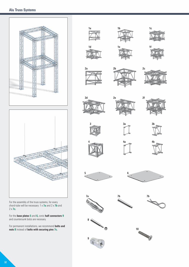
For the assembly of the truss systems, for every chord-tube will be necessary: 1 x 7a and 2 x 7b and 2 x 7c.
For the base plates 5 and 6, conic half connectors 9 and countersunk bolzs are necesary.
For permanent installations, we recommend bolts and nuts 8 instead of bolts with securing pins 7c.
1a
1d
2a
2d
3
4
5
7a
8
9
7b 7b
6
3a
4a
3b
4b
1b
1e
2b
2e
1c
1f
2c
2f
10
Alu Truss Systems
32
PA01022393_EN_Katalog_Event_2018.indd 32 09.03.2018 15:30:46
PA
0102
2418
_EN
_Kat
_Eve
nt_2
018.
PA
0102
2418
_EN
_Kat
_Eve
nt_2
018.
PA01022418_EN_Kat_Event_2018.pdf
PA01022418_EN_Kat_Event_2018.pdf

Pos. Description DimensionsL�/�H�x�W�[m]
Weight�approx.�[kg]
PU[pcs.]
Ref. No.
1abcdef
Truss�corners�H30V,�aluminium2-way, 90 degree3-way, 90 degree4-way, cross3-way, T-piece4-way, T-piece5-way
0.50 x 0.30 x 0.50 5.3 4 5723.003 P0.50 x 0.50 x 0.50 6.8 4 5723.012 P0.71 x 0.30 x 0.71 10.2 4 5723.016 P0.71 x 0.30 x 0.50 8.1 4 5723.017 P0.71 x 0.50 x 0.50 10.1 4 5723.020 P0.71 x 0.50 x 0.71 11.9 4 5723.024 P
2abcdef
Truss�corners�H40V,�aluminium2-way, 90 degree3-way, 90 degree4-way, cross3-way, T-piece4-way, T-piece5-way
0.60 x 0.40 x 0.60 7.0 4 5741.003 P0.60 x 0.60 x 0.60 9.2 4 5741.012 P0.80 x 0.40 x 0.80 12.8 4 5741.016 P0.80 x 0.40 x 0.60 10.5 4 5741.017 P0.80 x 0.60 x 0.60 12.8 4 5741.020 P0.80 x 0.60 x 0.80 15.1 2 5741.024 P
3ab
Box�Corner�H30V,�aluminiumAttachment SAttachment L
0.29 x 0.29 x 0.29 9.8 5714.030 P0.105 x 0.29 x 0.29 1.3 5 5714.031 P0.21 x 0.29 x 0.29 3.3 4 5714.032 P
4ab
Box�Corner�H40V,�aluminiumAttachment SAttachment L
0.39 x 0.39 x 0.39 12.1 4 5732.030 P0.105 x 0.39 x 0.39 1.5 4 5732.031 P0.21 x 0.39 x 0.39 3.3 5 5732.032 P
5 Base�plate�H30,�aluminium4-chord H30V 0.33 x 0.33 1.7 10 5701.073 P
6 Base�plate�H40,�aluminium4-chord H40V 0.43 x 0.43 2.9 10 5701.078 P
7abc
Connection partsConic connectorConic boltSecuring pin
0.09 0.2 100 5701.020 W0.07 0.01 100 5701.023 W0.06 0.01 100 5701.007 W
8 Conic bolt with nut M8 0.07 0.1 100 5701.024 W
9 Conic half connector with thread M12 0.04 0.2 50 5701.026 P
10 Countersunk�bolt�M12�x�20 0.02 0.05 50 5701.027 W
33
WS = wrench size PU = packaging unit W = available ex works P = delivery time on request V = only available in this packaging unit
PA01022393_EN_Katalog_Event_2018.indd 33 09.03.2018 15:30:46
PA
0102
2418
_EN
_Kat
_Eve
nt_2
018.
PA
0102
2418
_EN
_Kat
_Eve
nt_2
018.
PA01022418_EN_Kat_Event_2018.pdf
PA01022418_EN_Kat_Event_2018.pdf

299 299
dia. 48,30
569 569
dia. 48,30
452 452
dia. 48,30
550 854
dia. 60,30
Constructions, which are made to carry high loads and however must be easy and fast to assembly, need well-thought and strong components. Layher offers with the new steel truss the right tools for that challenge.
Tower Truss 1 The Tower Truss is a very strong transom type, which is especially usable for roofings as vertical support for constructions of Maxi Truss, as ground support, for advertisment signs or cable bridges.
Maxi�Truss�2 The Maxi Truss is a very strong transom type, which is especially usable for roofings as main transom, as ground support, for advertisment signs or cable bridges.
Nova Truss 3The Nova Truss is a very strong transom type, which is especially usable for roofings as vertical support for constructions of Super Truss, as ground support, for advertisment signs or cable bridges.
Super Truss 4 The Super Truss is a very strong transom type, which is especially usable for roofings as main transom, as ground support, for advertisment signs or cable bridges.
The steel truss elements will be produced individually according to your requirements. Do�not�hesitate�to�ask�us!�We�are�pleased�to�help�you.
Steel Truss Systems
43
12
5/6 7/8
34
PA01022393_EN_Katalog_Event_2018.indd 34 09.03.2018 15:30:49
PA
0102
2418
_EN
_Kat
_Eve
nt_2
018.
PA
0102
2418
_EN
_Kat
_Eve
nt_2
018.
PA01022418_EN_Kat_Event_2018.pdf
PA01022418_EN_Kat_Event_2018.pdf

Pos. Description DimensionsL�/�H�x�W�[m]
Weight�approx.�[kg]
Weight�per�metre�approx.�[kg]
PU[pcs.]
Ref. No.
1 Tower�Truss,�steel, hot-dip galvanized, 299 x 299 mmUsable for roofings as vertical support for constructions of Maxi Truss, as ground support, for advertisment signs or cable bridges, use with bolt dia. 15.8 mm
2.40 81.0 33.8 on request
4.00 127.7 31.9
5.00 152.6 30.5
2 Maxi�Truss,�steel, hot-dip galvanized, 569 x 569 mmUsable for roofings as main transom, as ground support, for advertisment signs or cable bridges, use with bolt dia. 15.8 mm
2.40 99.2 41.3 on request
4.00 156.9 39.2
5.00 191.0 38.2
3 Nova�Truss,�steel, hot-dip galvanized, 452 x 452 mmUsable for roofings as vertical support for constructions of Super Truss, as ground support, for advertisment signs or cable bridges, use with bolt dia. 15.8 mm
2.40 109.3 45.5 on request
4.00 184.9 46.2
5.00 227.4 45.5
4 Super�Truss,�steel, hot-dip galvanized, 550 x 854 mmUsable for roofings as main transom, as ground support, for advertisment signs or cable bridges, use with bolt dia. 20.0 mm
2.40 143.0 59.6 on request
4.00 239.0 59.8
5.00 291.2 58.2
5 Bolt, 15.8 x 80.0 mm for Tower Truss, Nova Truss and Maxi Truss
0.7 4 v 5550.001 W
6 Bolt, 20.0 x 100.0 mm for Super Truss
1.3 4 v 5550.002 W
7 Safety clip, 2.8 mm for Tower Truss, Nova Truss and Maxi Truss
0.5 50 v 4905.001
8 Safety clip, 4.0 mm for Super Truss
1.5 50 v 5905.001 W
35
WS = wrench size PU = packaging unit W = available ex works P = delivery time on request V = only available in this packaging unit
PA01022393_EN_Katalog_Event_2018.indd 35 09.03.2018 15:30:49
PA
0102
2418
_EN
_Kat
_Eve
nt_2
018.
PA
0102
2418
_EN
_Kat
_Eve
nt_2
018.
PA01022418_EN_Kat_Event_2018.pdf
PA01022418_EN_Kat_Event_2018.pdf

Steel Truss Systems
Span� [m] perm. line load p [kg�/�m]
Bending�[cm]of perm. p
perm. single load F�[kg]
Bending�[cm]of perm. F
perm. single load inthird points F1 [kg]
Bending�[cm]of perm. F1 [cm]
5 1968 0.4 7500 0.5 4919 0.6
6 1633 0.7 6215 0.8 4662 0.9
7 1395 1.2 5292 1.0 3969 1.2
8 1149 1.7 4595 1.4 3447 1.6
9 900 2.1 4049 1.7 3037 2.1
10 722 2.6 3608 2.1 2706 2.5
11 590 3.2 3244 2.6 2433 3.1
12 490 3.8 2938 3.1 2203 3.7
13 412 4.4 2675 3.6 2006 4.3
14 350 5.2 2448 4.2 1836 5.0
15 300 5.9 2248 4.9 1686 5.8
16 259 6.8 2071 5.6 1553 6.6
17 225 7.6 1912 6.4 1434 7.4
18 197 8.6 1769 7.2 1327 8.4
19 173 9.6 1639 8.0 1230 9.3
20 152 10.6 1521 9.0 1141 10.4
21 134 11.8 1411 10.0 1059 11.5
22 119 12.9 1310 11.0 983 12.6
23 106 14.2 1216 12.2 912 13.9
24 94 15.5 1129 13.3 846 15.1
25 84 16.8 1046 14.6 785 16.5
26 75 18.3 969 15.9 727 17.9
27 66 19.8 896 17.3 672 19.4
28 59 21.3 827 18.8 620 20.9
29 53 22.9 761 20.4 571 22.5
30 47 24.6 699 22.0 524 24.2
31 41 26.4 639 23.8 479 25.9
32 36 28.2 582 25.6 436 27.8
33 32 30.1 527 27.5 395 29.7
34 28 32.0 474 29.5 356 31.6
35 24 34.1 423 31.6 318 33.7
5 1539 0.5 5926 0.7 3848 0.7
6 1275 0.9 4900 1.0 3675 1.1
7 1087 1.5 4161 1.3 3120 1.6
8 900 2.1 3601 1.7 2701 2.0
9 702 2.7 3161 2.2 2371 2.6
10 561 3.3 2805 2.7 2103 3.2
11 456 4.0 2509 3.3 1882 3.9
12 377 4.8 2260 3.9 1695 4.6
13 315 5.6 2045 4.6 1534 5.4
14 265 6.5 1858 5.4 1394 6.3
15 226 7.5 1693 6.3 1270 7.3
16 193 8.5 1547 7.2 1160 8.3
17 166 9.7 1415 8.2 1061 9.4
18 144 10.9 1295 9.2 971 10.6
19 125 12.1 1186 10.4 889 11.9
20 109 13.5 1085 11.6 814 13.2
21 94 14.9 992 12.9 744 14.6
22 82 16.4 906 14.3 679 16.1
23 72 18.0 825 15.8 619 17.7
24 62 19.7 749 17.4 562 19.3
25 54 21.4 678 19.2 508 21.1
26 47 23.3 610 21.0 458 22.9
27 40 25.2 546 22.9 409 24.8
28 35 27.2 485 24.9 364 26.9
29 29 29.3 427 27.1 320 29.0
30 25 31.5 371 29.3 278 31.2
Nova Truss Systems
Maxi�Truss�Systems
36
PA01022393_EN_Katalog_Event_2018.indd 36 09.03.2018 15:30:50
PA
0102
2418
_EN
_Kat
_Eve
nt_2
018.
PA
0102
2418
_EN
_Kat
_Eve
nt_2
018.
PA01022418_EN_Kat_Event_2018.pdf
PA01022418_EN_Kat_Event_2018.pdf
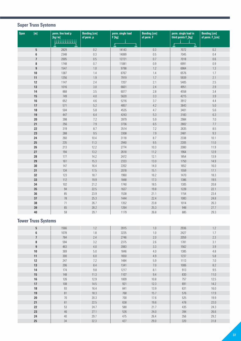
Span� [m] perm. line load p [kg�/�m]
Bending�[cm]of perm. p
perm. single load F�[kg]
Bending�[cm]of perm. F
perm. single load inthird points F1 [kg]
Bending�[cm]of perm. F1 [cm]
5 2829 0.2 14143 0.3 7072 0.2
6 2348 0.3 14089 0.5 7045 0.4
7 2005 0.5 12721 0.7 7018 0.6
8 1748 0.7 11081 0.9 6991 0.9
9 1547 1.0 9798 1.2 6964 1.3
10 1387 1.4 8767 1.4 6576 1.7
11 1256 1.9 7919 1.7 5939 2.1
12 1147 2.4 7207 2.1 5405 2.5
13 1016 3.0 6601 2.4 4951 2.9
14 868 3.5 6077 2.8 4558 3.4
15 749 4.0 5620 3.3 4215 3.9
16 652 4.6 5216 3.7 3912 4.4
17 571 5.2 4857 4.2 3643 5.0
18 504 5.8 4535 4.7 3401 5.6
19 447 6.4 4243 5.3 3183 6.3
20 398 7.2 3979 5.9 2984 7.0
21 356 7.9 3736 6.5 2802 7.7
22 319 8.7 3514 7.2 2635 8.5
23 288 9.5 3308 7.9 2481 9.3
24 260 10.4 3118 8.7 2338 10.1
25 235 11.3 2940 9.5 2205 11.0
26 213 12.2 2774 10.3 2080 11.9
27 194 13.2 2618 11.2 1964 12.9
28 177 14.2 2472 12.1 1854 13.9
29 161 15.3 2333 13.0 1750 14.9
30 147 16.4 2202 14.0 1652 16.0
31 134 17.5 2078 15.1 1559 17.1
32 123 18.7 1960 16.2 1470 18.3
33 112 19.9 1848 17.3 1386 19.5
34 102 21.2 1740 18.5 1305 20.8
35 94 22.5 1637 19.8 1228 22.1
36 85 23.9 1538 21.1 1154 23.4
37 78 25.3 1444 22.4 1083 24.8
38 71 26.7 1352 23.8 1014 26.3
39 65 28.2 1264 25.3 948 27.7
40 59 29.7 1179 26.8 885 29.3
5 1566 1.2 3915 1.0 2936 1.2
6 1078 1.8 3235 1.0 2427 1.7
7 784 2.4 2746 2.0 2059 2.3
8 594 3.2 2375 2.6 1781 3.1
9 463 4.0 2083 3.3 1562 3.9
10 369 5.0 1846 4.0 1385 4.8
11 300 6.0 1650 4.9 1237 5.8
12 247 7.2 1484 5.9 1113 7.0
13 206 8.4 1341 7.0 1006 8.2
14 174 9.8 1217 8.1 913 9.5
15 148 11.3 1107 9.4 830 11.0
16 126 12.9 1009 10.8 757 12.5
17 108 14.5 921 12.3 691 14.2
18 93 16.4 841 13.9 631 16.0
19 81 18.3 768 15.7 576 17.9
20 70 20.3 700 17.6 525 19.9
21 61 22.5 638 19.6 478 22.0
22 53 24.7 580 21.7 435 24.3
23 46 27.1 526 24.0 394 26.6
24 40 29.7 475 26.4 356 29.2
25 34 32.3 427 29.0 320 31.8
Super Truss Systems
Tower Truss Systems
37
PA01022393_EN_Katalog_Event_2018.indd 37 09.03.2018 15:30:50
PA
0102
2418
_EN
_Kat
_Eve
nt_2
018.
PA
0102
2418
_EN
_Kat
_Eve
nt_2
018.
PA01022418_EN_Kat_Event_2018.pdf
PA01022418_EN_Kat_Event_2018.pdf

Pos. Description
1 LayPLAN CAD plug-in for AutoCAD, for designing complex scaffolding in 3D
2 LayPLAN CAD OEM AutoCAD 2017 OEM with LayPLAN CAD plug-in for designing complex scaffolding in 3D, incl. 3D PDF exporter
Layher LayPLANTime and material are crucial factors in scaffolding construction. To make the most efficient use of both, the Layher range includes the practical LayPLAN scaffolding planning software.
LayPLAN CADFor more complex structures, LayPLAN CAD is available. This is a plug-in for Autodesk AutoCAD. It enables 3-dimensional planning of scaffolding structures of all types.
Thanks to integration into the LayPLAN system, the basic planning can be handled in automated form using the proven LayPLAN CLASSIC. Project data can be quickly recorded using input masks, ensuring a time saving for every order. The data are then simply exported into the AutoCAD program, which offers further possibilities for detailed 3D planning. A visual collision check is possible with the aid of volume rendering. Using a convenient search function with preview image, scaffolding planners will find not only an extensive library of individual Layher parts, but also assemblies already prefabricated for even faster design work. The detailed drawings can then be printed out. It is possible to export them as 3D PDFs too (3D PDF exporter only included with LayPLAN CAD OEM version), which brings benefits in the tender phase and also facilitates later assembly. A transfer to visualisation or animation software is also possible without any problem. This allows projects not only to be planned economically and also adapted precisely to actual requirements, but also to be presented professionally to customers.
LayPLAN Material ManagerPart of LayPLAN CAD
Planning of a grandstand in LayPLAN CAD
Software for scaffolding construction
38
PA01022393_EN_Katalog_Event_2018.indd 38 09.03.2018 15:30:53
PA
0102
2418
_EN
_Kat
_Eve
nt_2
018.
PA
0102
2418
_EN
_Kat
_Eve
nt_2
018.
PA01022418_EN_Kat_Event_2018.pdf
PA01022418_EN_Kat_Event_2018.pdf

AAdaptor with rosette 21
Adaptor with spigot 21
Allround wedge 21
Aluminium frame for tip-up seat 21
Assembly-Set 21
BBase beam 15
Base collar 11, 12
Base collar for modular stairway 13
Base plate20 1140 11H30 33type 1 15type 2 15
Basic components 10, 18
Bench 20, 21
Bench adaptor 21
Bench end 20, 21
Boltdia. 15.80 mm 35M10 x 70 19
Box CornerH30V 33H40V 33
Bucket seats 20
CCaptive bolt
for keder rail 27
ClampT4, T1 11T10, T7 11T16 11
Conic bolt 33
Conic half connector 33
Connection part 33
Corner guardrail 19
EEvent access deck 27
Event deck 10, 11
Event stage 8
Event stands 16
Event transom 10, 11
FFOH beam 27
FOH entrance 25
FOH projecting rooffor 2 bays 25for 3 bays 25
FOH rope holder set 27
FOH System 22, 24, 26
FOH Tower 25
FOH Tower KIT system 22
GGuardrail for modular stairway 13
Guardrail for stands 18
Guardrail post 18
Guardrail post for podium 13
Guardrail standard 18, 19
Guardrail with child safety features 12, 13
HHalf-coupler 27
Handrail 12, 13
Hinged attachment 27
IIntermediate step 19
KKeder rail
2000 26, 273000 26, 279000 26, 27holder 27
LLayPLAN 38
Lift-off preventer 13, 19
Lift-off preventer for steel decks 19
Lock against lift-off 18ST 86 18
MMaxi Truss 35
NNovanta bucket seat 20, 21
Nova Truss 35
Number plate 21
OO-ledger 12, 13
PPlastic corner 10
T1 11T4, T7, T10 11T16 11
Plug 21
Podia 8
RRoof and wall cladding 22, 26
Rope fastenerfor ballast bays 27for roof stiffening 27
Rubber pad 10, 11
SSeating stand 7
Seat support with rosette 20, 21
Short wedge 20
Side end guardrail 19
Side guardrail 19EV 86, rise 166 mm 18EV 100/EV 104, rise 250 mm 18
Single step ladder 27
Special bolt with nut 15
Square half-coupler 10, 11
Stage 6
Stairway 12
Stairway guardrail 750 13
Stairway stringer 12
Standard0.67 m 10, 111.17 m 10, 11
Standard 0.92 m with adaptor 21
Standard 1.18 m with adaptor 21
Standard for modular stairway 13
Stand element1-step 18, 192-step 18, 19
Stands 7, 16
Steel deck support 18, 19
Stringer for modular stairway 12, 13
Super Truss 35
TTension clasp 10, 11
Tip-up seat 21
Tower Truss 35
Transom support 10, 11
TrussH30V 31H40V 31
Truss cornersH30V 33H40V 33
Truss System 28alu 30, 32steel 34, 36
Truss-Transom 15
UUniversal Base 14
U-Stairway stringer750 13
Index
39
PA01022393_EN_Katalog_Event_2018.indd 39 09.03.2018 15:30:53
PA
0102
2418
_EN
_Kat
_Eve
nt_2
018.
PA
0102
2418
_EN
_Kat
_Eve
nt_2
018.
PA01022418_EN_Kat_Event_2018.pdf
PA01022418_EN_Kat_Event_2018.pdf
Ref.
No.
811
1.23
0
Editi
on 0
4.20
18
Wilhelm�Layher�GmbH�&�Co�KGScaffolding Grandstands Ladders
Ochsenbacher Strasse 5674363 Gueglingen-EibensbachGermany
Post Box 4074361 Gueglingen-EibensbachGermanyTelephone +49 (0) 71 35 70-0Telefax +49 (0) 71 35 70-2 65E-mail [email protected]
Proximity to the customer is a central factor behind Layher’s success – geographically speak- ing too. Wherever our customers need us, we will be there – with our advice, assistance and solutions.
Layher is your dependable partner with more than 70 years of experience. ”Made by Layher“ always means ”Made in Germany“ too – and that goes for the entire product range. Superb quality – and all from one source.
Headquarters in Eibensbach
Plant 2 in Gueglingen
SpeedyScaf
Allround Scaffolding
Event Systems
System-free Accessories
Protective Systems
Shoring
Rolling Towers
Ladders
PA01022393_EN_Katalog_Event_2018.indd 40 09.03.2018 15:31:03
PA
0102
2418
_EN
_Kat
_Eve
nt_2
018.
PA
0102
2418
_EN
_Kat
_Eve
nt_2
018.
PA01022418_EN_Kat_Event_2018.pdf
PA01022418_EN_Kat_Event_2018.pdf