laser engineering of biomimetic surfaces revised finaltt
TRANSCRIPT
Laser engineering of biomimetic surfaces
E.Stratakis1,2,J.Bonse3,J.Heitz4,J.Siegel5,G.D.Tsibidis1,E.Skoulas1,6,A.
Papadopoulos1,6,A.Mimidis1,6,A.-C.Joel7,P.Comanns7,J.Krüger3,C.Florian5,Y.
Fuentes-Edfuf5,J.Solis5,W.Baumgartner8
1 InstituteofElectronicStructureandLaser,FoundationforResearchandTechnology-Hellas,
Heraklion,71110Crete,Greece2DepartmentofPhysics,UniversityofCrete,70013Heraklion,Greece3BundesanstaltfürMaterialforschungund−prüfung(BAM),12205Berlin,Germany
4InstituteofAppliedPhysics,JohannesKeplerUniversityLinz,4040Linz,Austria5LaserProcessingGroup,InstitutodeOptica(IO-CSIC),ConsejoSuperiordeInvestigaciones
Científicas,CSIC,28006Madrid,Spain
6DepartmentofMaterialsScienceandTechnology,UniversityofCrete,70013Heraklion,
Greece
7 InstituteforZoology,RWTHAachenUniversity,52074Aachen,Germany8InstituteofBiomedicalMechatronics,JohannesKeplerUniversityLinz,4040Linz,Austria
Abstract The exciting properties of micro- and nano-patterned surfaces found in natural species hide a virtually
endless potential of technological ideas, opening new opportunities for innovation and exploitation in
materials science and engineering. Due to the diversity of biomimetic surface functionalities,
inspirations from natural surfaces are interesting for a broad range of applications in engineering,
including phenomena of adhesion, friction, wear, lubrication, wetting phenomena, self-cleaning,
antifouling, antibacterial phenomena, thermoregulation and optics. Lasers are increasingly proving to
be promising tools for the precise and controlled structuring of materials at micro- and nano-scales.
When ultrashort-pulsed lasers are used, the optimal interplay between laser and material parameters
enables structuring down to the nanometer scale. Besides this, a unique aspect of laser processing
technology is the possibility for material modifications at multiple (hierarchical) length scales, leading
to the complex biomimetic micro- and nano-scale patterns, while adding a new dimension to structure
optimization. This article reviews the current state of the art of laser processing methodologies, which
are being used for the fabrication of bioinspired artificial surfaces to realize extraordinary wetting,
optical, mechanical, and biological-active properties for numerous applications. The innovative aspect
of laser functionalized biomimetic surfaces for a wide variety of current and future applications is
particularly demonstrated and discussed. The article concludes with illustrating the wealth of arising
possibilities and the number of new laser micro/nano fabrication approaches for obtaining complex
high-resolution features, which prescribe a future where control of structures and subsequent
functionalities are beyond our current imagination.
Keywords: Biomimetic surfaces; Laser Processing; Surface Functionalization; Bioinspiration; Bionic
materials
1 Introduction The study and replication of biological systems is popularly known as biomimetics - a combination of
the Greek words ‘bios’, meaning life, and ‘mimesis’, meaning to imitate. Nature offers a diverse
wealth of functional surfaces, which properties are unmatched in today’s artificial materials. Such
solutions came as a direct consequence of evolutionary pressure, which forces natural species to
become highly optimized and efficient. The adaptation of natural methods and systems into synthetic
constructs is therefore desirable, and nature provides a unique source of working solutions, which can
serve as models of inspiration for synthetic paradigms. In this context, a highly interdisciplinary field
of research developed concerning the design, synthesis, and fabrication of biomimetic structures,
based on the ideas, concepts, and underlying principles developed by nature. Biomimetic materials
provide innovative solutions for the design of a new generation of functional materials and can lead to
novel material design principles.
Currently, a large area of biomimetic research deals with water repellency, self-cleaning, drag and
friction reduction in fluid flow, energy conversion and conservation, adhesion, aerodynamic lift,
composite materials with high mechanical strength, antireflection, structural coloration, thermal
insulation, antifouling, antibacterial and self-healing properties. All these exceptional functionalities
are demonstrated by natural systems and are based on a variety of ingenious designs of biological
surfaces, achieved through a sophisticated control of structural features at all length scales, starting
from the macroscopic world down to the finest detail, right down to the level of atom. Therefore,
natural surfaces are organized in a rather complex manner, exhibiting hierarchical structuring at all
length scales.
In this context, several methodologies have been developed to facilitate the formation of
bioinspired surfaces exhibiting hierarchical structuring at length scales ranging from hundreds of
nanometers to several microns. Laser processing excels over mechanical, chemical, and electric
discharge texturing as it allows local modifications with a large degree of control over the shape and
size of the features, which are formed, and a broader range of sizes, which can be fabricated. Besides
this, laser structuring techniques can be readily incorporated to computer aided design and
manufacture systems for complex and customized surface texture designs and subsequently
reproducible and cost-effective fabrication. This can give rise to a versatile class of laser-based rapid
prototyping texturing systems that could potentially be commercialized for mass production and thus
attract considerable attention in the following years.
This article reviews the current state of the art of laser processing methodologies used for the
fabrication and engineering of biomimetic surfaces to realize extraordinary optical, mechanical,
chemical, wetting, biological-active and tribological properties for numerous applications. In parallel,
the biological principles behind the functionalities exhibited by the natural surface archetypes will be
analyzed and discussed. Besides presenting the potential and significance of the laser based
biomimetic surface structures, it will also delineate existing limitations and discuss emerging
possibilities and future prospects.
2 Learning from nature: Design principles of natural surfaces
2.1 Optical properties
There are very few examples, where color plays no role in the life of an animal or plant. For
example for troglobionts (i.e. cave dwellers) colors (as well as eyes) play no role as there is no or little
light to reflect [1–3] .
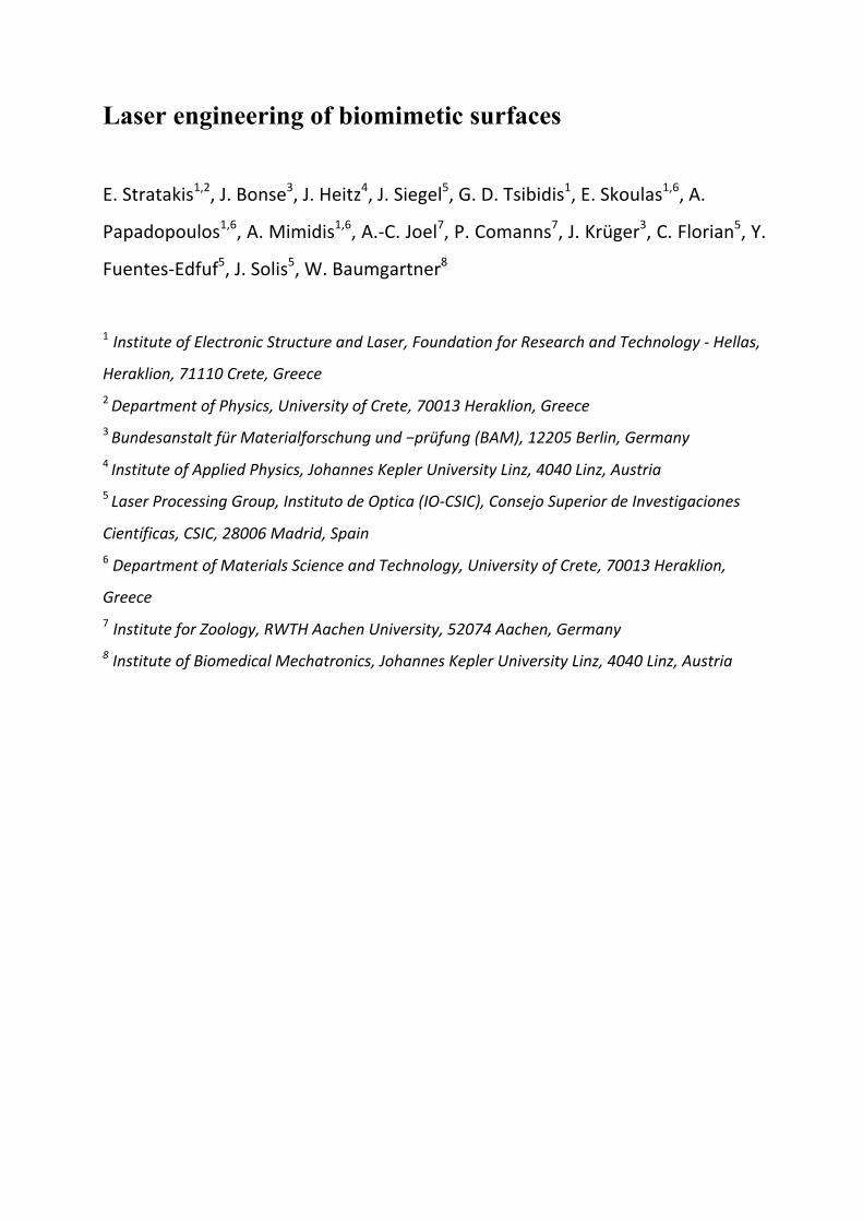
Fig.1:Examples of biological systems with optical properties, photographs of the actual animal and the corresponding SEM image below. The Morpho butterfly with the scales of its wing (a-b), the snout weevil and the ultrastructure of the elytra (i.e. modified forewings) (c-d), as well as the peacock spider and its iridescent scales (e-f) show structural coloration. Structural antireflection was proven for the glasswing butterfly (g-h), a cicada with the nanopillars on its wing (i-j), and the moth’s eyes (k-l). Sources: (a), licensed by Didier Descouens / CC-BY-SA-4.0 (Wikimedia Commons). (b), reprint permission from Rashmi Nanjundaswamy / Lawrence Hall of Science CC BY-NC-SA 3.0 US. (c), printed with permission from Javier Rupérez, Spanish photographer specializing in extreme macro photography (www.javier-ruperez.com), (d),reprinted from ref [4] with permission from American Physical Society. (e) and (f), reprinted with permission from [5] Springer Nature (Creative Commons
CC BY 4.0). (g), licensed by David Tiller CC BY-SA 3.0 (Wikimedia Commons). (h) reprint with permission from ref [6], Licensed by Radwanul H., CC BY-SA 3.0 (Wikimedia Commons). (i), licensed by Gail Hampshire CC BY-SA 2.0 (Wikimedia Commons). (j) reprint with permission from ref [7] by John Wiley & Sons. (k), licensed by Ben Sale CC BY-SA 2.0 (Wikimedia Commons). (l), Dartmouth college.
On the contrary, through natural selection and evolutionary pressure nature offers multifarious sub-
micrometer surface morphologies producing colorful structures playing a crucial role on the species
survival [8]. Numerous of biological systems have been studied from the ancient times until the
present for their ability to utilize light for their own advantage. Coloration arising from living
organisms was mentioned ~2000 years ago from Aristotle [9], intrigued Robert Hooke in 1665 to
study insects, plants and cells in “Micrographia” [10], while the peacock’s feather coloration is
mentioned in 1704 Newton’s “Opticks” for reflection, infections and colors of light [11] and finally
the “Animal coloration” in 1892 from F.E. Beddard was the first dedicated study to deal with the ways
that biological systems produce color [12]. The most prominent functionalities of biological light
manipulation are signaling, e.g. to attract conspecifics [13] and pollinators or to scare off predators
[14–18], drably colors are often used as disguise and camouflage [19,20], while depending of the
ambient characteristics their “optical necessity” may vary and can be attributed as extreme light
absorption [21], anti-reflection [22] or selective reflection (iridescence) [23,24].
The ability of living organisms to produce color can be attributed to light interference, scattering
(structural coloration), selective wavelength absorption (pigmentation), or both. Structural coloration
can be produced by the interaction between light and nanometer-scale variation in the integumentary
tissues. The most prominent mechanisms responsible for producing structural color or anti-reflection
have been summarized in several reviews [25–29]. Tyndall or Mie scattering, which favors the
redirection of short-wavelength radiation, is an example of such filtering by extremely small
(subwavelength) boundaries. Interference from variation of the optical path due to reflections on
periodic or pseudo-periodic tissue formation is responsible for iridescence similar to grating effects.
Furthermore, the gradient refractive index that can be produced collectively from subwavelength
three-dimensional nanostructures in the main physical phenomena that nature utilizes for extremely
low light reflection and high transmissivity [30]. Fig. 1 presents some of the most important biological
paradigms for structural coloration and structural antireflective optical properties, which are discussed
in the following sections.
The physical mechanisms, which describe most of the optical phenomena found in natural
organisms, are summarized in Fig. 2. Most anti-reflective architectures in nature are not attributed to a
layered thin film with a refractive index (n) on a substrate with (ns), where ns > n (Fig. 2A-a). On the
contrary, species utilize surface morphological features like barbule microstructures on the feather
birds of paradise (Fig. 2A-b) to induce light trapping by multiple reflections, leading to a very black
color [31,32]. Micro- and nanostructure arrays like the moth's eye or cicada’s wing can gradually
reduce the refractive index from the material (wing) (n2) to the refractive index of air (n1) resulting on
extremely low reflectance values (Fig. 2A-c-d). J.C.M. Garnett [33] and D.A.G. Bruggeman [34]
considered simple models like “effective medium theory” to analyze rough surfaces. A layer with
microscopic surface roughness can be considered as multiple layers of the ‘‘effective medium’’ having
refractive index in the limit of the substrate and ambient (air in most cases). The “effective refractive
index” (n) of the ‘‘effective medium’’ can be approximated from the volume fractions (f) of the
individual rough layers. Assuming the ‘‘effective medium’’ as a set of two layers, the Maxwell
Garnett model, predicts that the effective (n) for a layer with n2 surrounded by the other layer with n1
will be given by:
(𝑛! − 𝑛!!)(𝑛! + 2𝑛!!)
= (1 − 𝑓!)(𝑛!! − 𝑛!!)(𝑛!! + 2𝑛!!)
Eq. 1
where n1 and n2 are the refractive indexes of two constituent layers, f1 and f2 (= 1 - f1) are the
corresponding volume fractions. While at the Bruggeman model, ‘‘effective medium’’ is assumed a
homogeneous mixture of two constituent layers, where:
𝑓!(𝑛!! − 𝑛!)(𝑛!! + 2𝑛!)
+ 𝑓!(𝑛!! − 𝑛!)(𝑛!! + 2𝑛!)
= 0 Eq. 2
Other optical processes related to structural colors associate with single and multiple film
interference. Let a plane wave of light be incident on a thin film with thickness d and refractive index
nb and the angles of incidence and refraction as θa and θb (Fig. 2B). Using the soap-bubble case, the
condition for constructive interference becomes:
2𝑛!𝑑𝑐𝑜𝑠𝜃! = (𝑚 − 1/2)𝜆 Eq. 3
where λ is the wavelength with the maximum reflectivity and m is an integer. Moreover, multilayer
thin film interference is a pair of thin layers stacked periodically. Assuming we have two layers, A and
B with the corresponding thicknesses dA and dB, and refractive indexes, nA > nB, respectively, as
shown in Fig. 2C. If we consider a certain pair of AB layers, the phases of the reflected light both at
the upper and lower B–A interfaces change by 180°. Thus, a relation similar to the anti-reflective
coating of eq. (3) is applicable as:
2(𝑛!𝑑! 𝑐𝑜𝑠 𝜃! + 𝑛!𝑑! 𝑐𝑜𝑠 𝜃!) = 𝑚𝜆 Eq. 4
for constructive interference with the angles of refraction in the A and B layers as θA and θB.
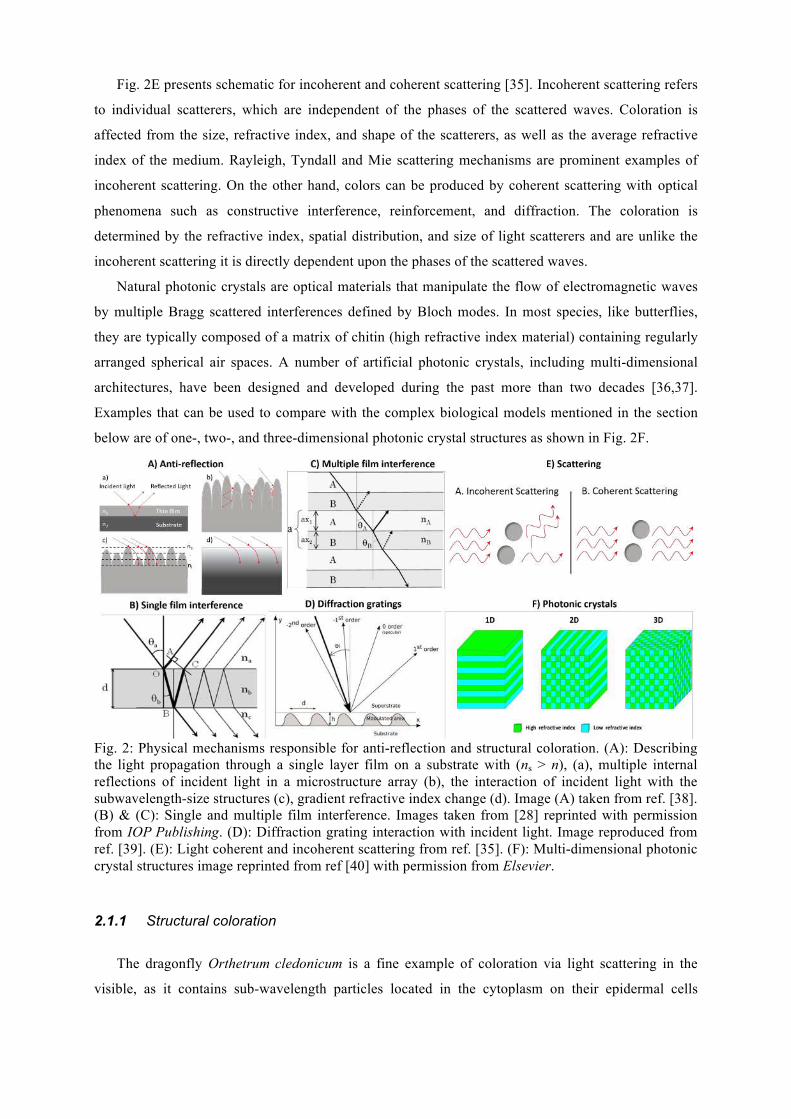
Fig. 2E presents schematic for incoherent and coherent scattering [35]. Incoherent scattering refers
to individual scatterers, which are independent of the phases of the scattered waves. Coloration is
affected from the size, refractive index, and shape of the scatterers, as well as the average refractive
index of the medium. Rayleigh, Tyndall and Mie scattering mechanisms are prominent examples of
incoherent scattering. On the other hand, colors can be produced by coherent scattering with optical
phenomena such as constructive interference, reinforcement, and diffraction. The coloration is
determined by the refractive index, spatial distribution, and size of light scatterers and are unlike the
incoherent scattering it is directly dependent upon the phases of the scattered waves.
Natural photonic crystals are optical materials that manipulate the flow of electromagnetic waves
by multiple Bragg scattered interferences defined by Bloch modes. In most species, like butterflies,
they are typically composed of a matrix of chitin (high refractive index material) containing regularly
arranged spherical air spaces. A number of artificial photonic crystals, including multi-dimensional
architectures, have been designed and developed during the past more than two decades [36,37].
Examples that can be used to compare with the complex biological models mentioned in the section
below are of one-, two-, and three-dimensional photonic crystal structures as shown in Fig. 2F.
Fig. 2: Physical mechanisms responsible for anti-reflection and structural coloration. (A): Describing the light propagation through a single layer film on a substrate with (ns > n), (a), multiple internal reflections of incident light in a microstructure array (b), the interaction of incident light with the subwavelength-size structures (c), gradient refractive index change (d). Image (A) taken from ref. [38]. (B) & (C): Single and multiple film interference. Images taken from [28] reprinted with permission from IOP Publishing. (D): Diffraction grating interaction with incident light. Image reproduced from ref. [39]. (E): Light coherent and incoherent scattering from ref. [35]. (F): Multi-dimensional photonic crystal structures image reprinted from ref [40] with permission from Elsevier.
2.1.1 Structural coloration
The dragonfly Orthetrum cledonicum is a fine example of coloration via light scattering in the
visible, as it contains sub-wavelength particles located in the cytoplasm on their epidermal cells
resulting in a permanent blue coloration and red when viewed in transmission [27]. The exact shade of
blue dependents only on the particle size. Another case can be observed when studying the Morpho
butterfly, one of the best studied biological models for structural coloration produced by multi-layer
reflections on the 3D structures of its scales [41]. However, sophisticated diffraction gratings are
remarkably widespread throughout nature. In latest studies, peacock spiders such as Maratus robinsoni
and Maratus chrysomelas have hairs with 2D nanogratings on microscale 3D convex surfaces, which
can yield at least twice the resolving power of a conventional 2D diffraction grating with the same
characteristics [5]. Remarkable tuning of structural colors are also produced due to a 3D photonic
crystal network of chitin in air with a single diamond (Fd-3m) symmetry found on the elytra (i.e.
modified forewings) of snout weevil, Pachyrrhynchus congestus pavonius [42].
Besides tunable structural coloring effects, non-iridescent colors in nature are produced by
coherent scattering of light by quasi-ordered, amorphous photonic structures can be found on
tarantulas Poecilotheria metallica and Lampropelma violaceopes [43]. Simple photonic structures
attained by biological systems such as the sea mouse Aphroditidae (Polychaeta) reflect the complete
visible spectrum over a range of small incident angles with a reflectivity of 100 % to the human eye
[23]. Much more complex photonic architectures have been studied in butterflies, which have a three-
dimensional periodicity, frequently enhanced by secondary structures which perform a cruder, more
generalized, light-scattering or directing role and, thereby, modify the photonic crystal’s effects [44].
The diversity and functionality of structures responsible for all these effects is a remarkable example
of photonic engineering by living organisms.
2.1.2 Structural anti-reflection
Although most of the natural systems are associated with vivid color or broad angle reflectivity,
nature has also provided nanostructures for extremely low reflectivity without transmission loses over
broad angles or frequency ranges, or even both. The majority of biological systems gifted with these
abilities are insects, which benefit from anti-reflective surfaces either on their eyes for night vision or
on their wings to eliminate reflections for the purpose of camouflage and keep their body warm during
the day.
Most prominent examples are the moth’s and butterfly’s eyes and the transparent wings of cicadas.
In these cases, antireflection is achieved by using subwavelength, nanosized three-dimensional surface
architectures. These structure architectures form a gradient refractive index and transmits light with
extremely low loses. For instance, the surface of a moth’s eye comprises conical nodules with rounded
tips arranged in a hexagonal array with variable spatial characteristics depending on the species [16].
Cicada’s wing structure is different to those of the moth’s eyes, as they resemble nanopillars. The
cuticles of such insects consist of self-assembled polysaccharides (i.e. chitin) and proteinaceous
materials chitin and its derivatives. Their spatial characteristics range in height from approximately
100 to 340 nm, depending on the species and the location of the structure on the wing [20]. However,
their anti-reflective properties are remarkable and for a wide range of angles of incidence [22].
Another profound example of nature anti-reflective structures in the glass wing butterfly Greta oto
[45]. The random nanostructures on the transparent part of its wing average in distance between the
pillars at 120 ± 20 nm and typical height ranging from 160 to 200 nm. Moreover the optical properties
of the wing exhibit a stunning low haze and reflectance over the whole visible spectral range even for
large view angles of 80° [6].
2.2 Wetting
Many animals or plants exhibit surfaces with specialized wetting properties. A combination of surface
chemistry and structure (or roughness) causes a spreading or repelling of a liquid. Spreading occurs
particularly in animals, which can use their body surface to collect water passively from various
sources. This includes arthropods, amphibians, reptiles, birds and even mammals [46–53]. Some of the
corresponding surface structures have been transferred to artificial materials using lasers (cf. Table 1).
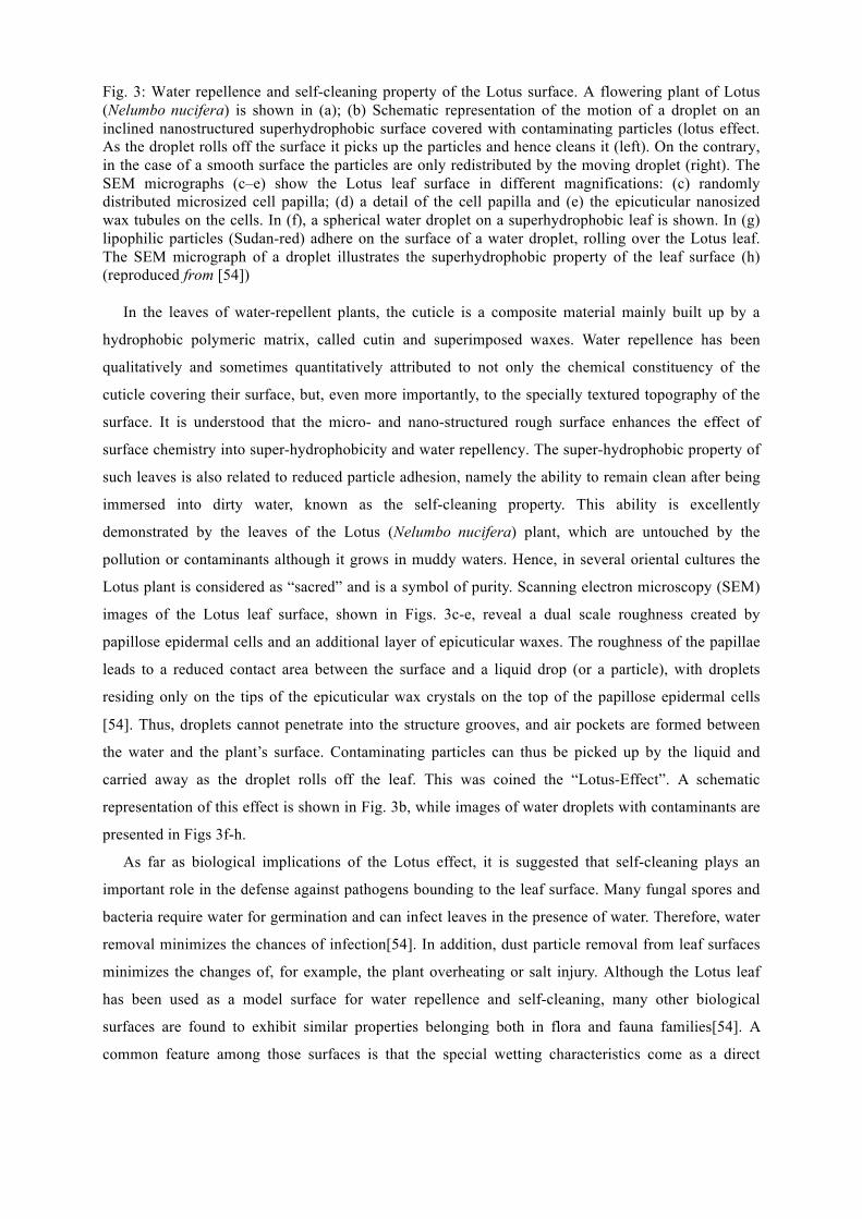
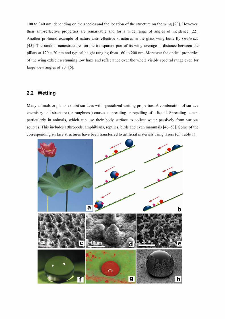
Fig. 3: Water repellence and self-cleaning property of the Lotus surface. A flowering plant of Lotus (Nelumbo nucifera) is shown in (a); (b) Schematic representation of the motion of a droplet on an inclined nanostructured superhydrophobic surface covered with contaminating particles (lotus effect. As the droplet rolls off the surface it picks up the particles and hence cleans it (left). On the contrary, in the case of a smooth surface the particles are only redistributed by the moving droplet (right). The SEM micrographs (c–e) show the Lotus leaf surface in different magnifications: (c) randomly distributed microsized cell papilla; (d) a detail of the cell papilla and (e) the epicuticular nanosized wax tubules on the cells. In (f), a spherical water droplet on a superhydrophobic leaf is shown. In (g) lipophilic particles (Sudan-red) adhere on the surface of a water droplet, rolling over the Lotus leaf. The SEM micrograph of a droplet illustrates the superhydrophobic property of the leaf surface (h) (reproduced from [54])
In the leaves of water-repellent plants, the cuticle is a composite material mainly built up by a
hydrophobic polymeric matrix, called cutin and superimposed waxes. Water repellence has been
qualitatively and sometimes quantitatively attributed to not only the chemical constituency of the
cuticle covering their surface, but, even more importantly, to the specially textured topography of the
surface. It is understood that the micro- and nano-structured rough surface enhances the effect of
surface chemistry into super-hydrophobicity and water repellency. The super-hydrophobic property of
such leaves is also related to reduced particle adhesion, namely the ability to remain clean after being
immersed into dirty water, known as the self-cleaning property. This ability is excellently
demonstrated by the leaves of the Lotus (Nelumbo nucifera) plant, which are untouched by the
pollution or contaminants although it grows in muddy waters. Hence, in several oriental cultures the
Lotus plant is considered as “sacred” and is a symbol of purity. Scanning electron microscopy (SEM)
images of the Lotus leaf surface, shown in Figs. 3c-e, reveal a dual scale roughness created by
papillose epidermal cells and an additional layer of epicuticular waxes. The roughness of the papillae
leads to a reduced contact area between the surface and a liquid drop (or a particle), with droplets
residing only on the tips of the epicuticular wax crystals on the top of the papillose epidermal cells
[54]. Thus, droplets cannot penetrate into the structure grooves, and air pockets are formed between
the water and the plant’s surface. Contaminating particles can thus be picked up by the liquid and
carried away as the droplet rolls off the leaf. This was coined the “Lotus-Effect”. A schematic
representation of this effect is shown in Fig. 3b, while images of water droplets with contaminants are
presented in Figs 3f-h.
As far as biological implications of the Lotus effect, it is suggested that self-cleaning plays an
important role in the defense against pathogens bounding to the leaf surface. Many fungal spores and
bacteria require water for germination and can infect leaves in the presence of water. Therefore, water
removal minimizes the chances of infection[54]. In addition, dust particle removal from leaf surfaces
minimizes the changes of, for example, the plant overheating or salt injury. Although the Lotus leaf
has been used as a model surface for water repellence and self-cleaning, many other biological
surfaces are found to exhibit similar properties belonging both in flora and fauna families[54]. A
common feature among those surfaces is that the special wetting characteristics come as a direct
consequence of the synergy of micro- and nano-structured morphology and hydrophobic surface
chemistry.
Flat bugs live on bark of trees and highly rely on their camouflage appearance. Some species,
living in tropical South America, can cope with moisture induced color change of the bark. Unlike
most other insects, they have a highly wettable body surface and change color when wetted. This
unique mechanism of camouflage, i.e. a rapid and passive spreading of water over the body surface,
results from almost superhydrophilic wetting properties. Here, hydrophilicity is enabled mainly by
significant amounts of the chemical component erucamide in the surface wax layer and is enhanced by
pillar-like surface microstructures [55–60].
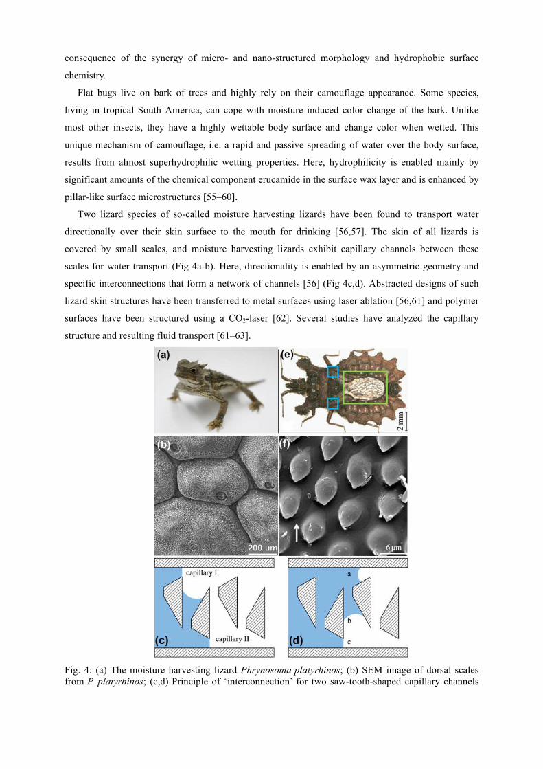
Two lizard species of so-called moisture harvesting lizards have been found to transport water
directionally over their skin surface to the mouth for drinking [56,57]. The skin of all lizards is
covered by small scales, and moisture harvesting lizards exhibit capillary channels between these
scales for water transport (Fig 4a-b). Here, directionality is enabled by an asymmetric geometry and
specific interconnections that form a network of channels [56] (Fig 4c,d). Abstracted designs of such
lizard skin structures have been transferred to metal surfaces using laser ablation [56,61] and polymer
surfaces have been structured using a CO2-laser [62]. Several studies have analyzed the capillary
structure and resulting fluid transport [61–63].
Fig. 4: (a) The moisture harvesting lizard Phrynosoma platyrhinos; (b) SEM image of dorsal scales from P. platyrhinos; (c,d) Principle of ‘interconnection’ for two saw-tooth-shaped capillary channels
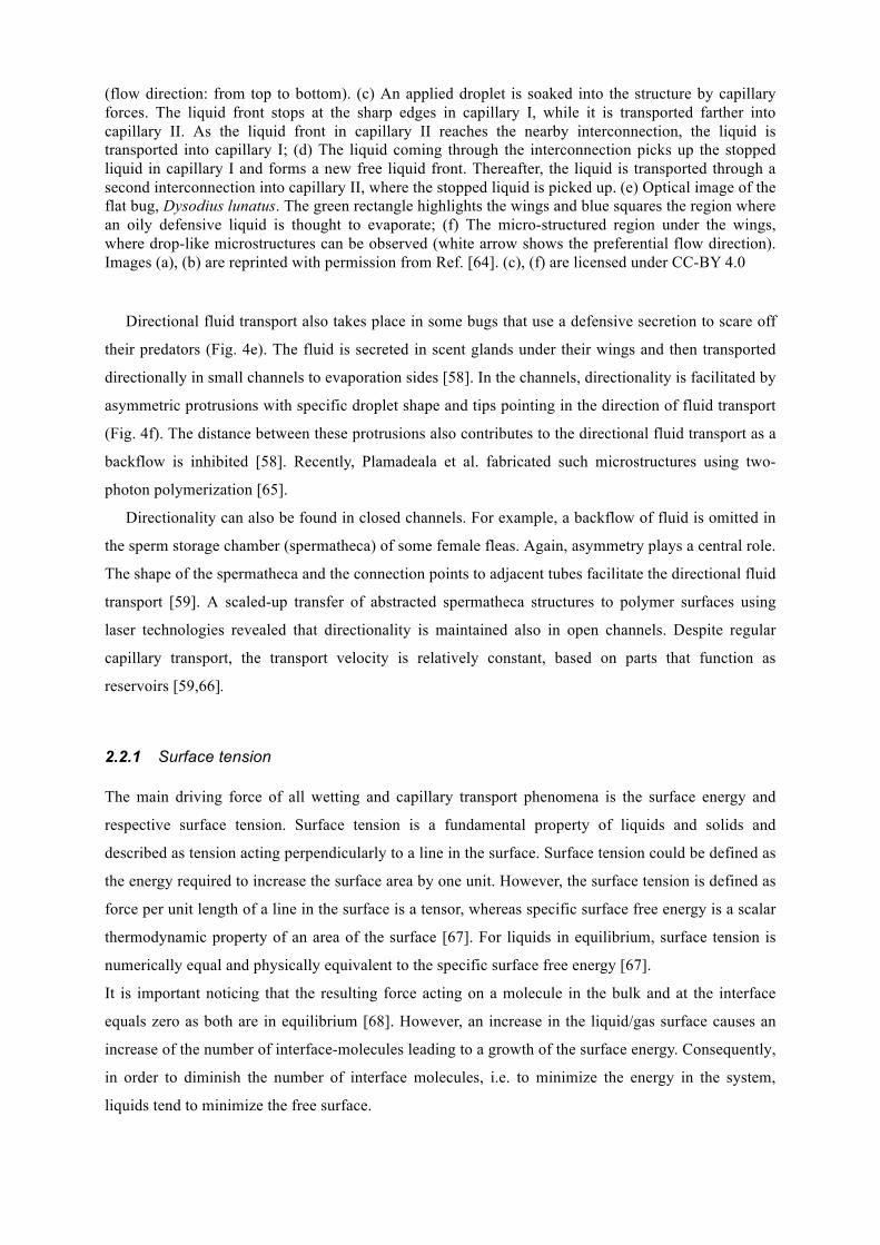
(flow direction: from top to bottom). (c) An applied droplet is soaked into the structure by capillary forces. The liquid front stops at the sharp edges in capillary I, while it is transported farther into capillary II. As the liquid front in capillary II reaches the nearby interconnection, the liquid is transported into capillary I; (d) The liquid coming through the interconnection picks up the stopped liquid in capillary I and forms a new free liquid front. Thereafter, the liquid is transported through a second interconnection into capillary II, where the stopped liquid is picked up. (e) Optical image of the flat bug, Dysodius lunatus. The green rectangle highlights the wings and blue squares the region where an oily defensive liquid is thought to evaporate; (f) The micro-structured region under the wings, where drop-like microstructures can be observed (white arrow shows the preferential flow direction). Images (a), (b) are reprinted with permission from Ref. [64]. (c), (f) are licensed under CC-BY 4.0
Directional fluid transport also takes place in some bugs that use a defensive secretion to scare off
their predators (Fig. 4e). The fluid is secreted in scent glands under their wings and then transported
directionally in small channels to evaporation sides [58]. In the channels, directionality is facilitated by
asymmetric protrusions with specific droplet shape and tips pointing in the direction of fluid transport
(Fig. 4f). The distance between these protrusions also contributes to the directional fluid transport as a
backflow is inhibited [58]. Recently, Plamadeala et al. fabricated such microstructures using two-
photon polymerization [65].
Directionality can also be found in closed channels. For example, a backflow of fluid is omitted in
the sperm storage chamber (spermatheca) of some female fleas. Again, asymmetry plays a central role.
The shape of the spermatheca and the connection points to adjacent tubes facilitate the directional fluid
transport [59]. A scaled-up transfer of abstracted spermatheca structures to polymer surfaces using
laser technologies revealed that directionality is maintained also in open channels. Despite regular
capillary transport, the transport velocity is relatively constant, based on parts that function as
reservoirs [59,66].
2.2.1 Surface tension The main driving force of all wetting and capillary transport phenomena is the surface energy and
respective surface tension. Surface tension is a fundamental property of liquids and solids and
described as tension acting perpendicularly to a line in the surface. Surface tension could be defined as
the energy required to increase the surface area by one unit. However, the surface tension is defined as
force per unit length of a line in the surface is a tensor, whereas specific surface free energy is a scalar
thermodynamic property of an area of the surface [67]. For liquids in equilibrium, surface tension is
numerically equal and physically equivalent to the specific surface free energy [67].
It is important noticing that the resulting force acting on a molecule in the bulk and at the interface
equals zero as both are in equilibrium [68]. However, an increase in the liquid/gas surface causes an
increase of the number of interface-molecules leading to a growth of the surface energy. Consequently,
in order to diminish the number of interface molecules, i.e. to minimize the energy in the system,
liquids tend to minimize the free surface.
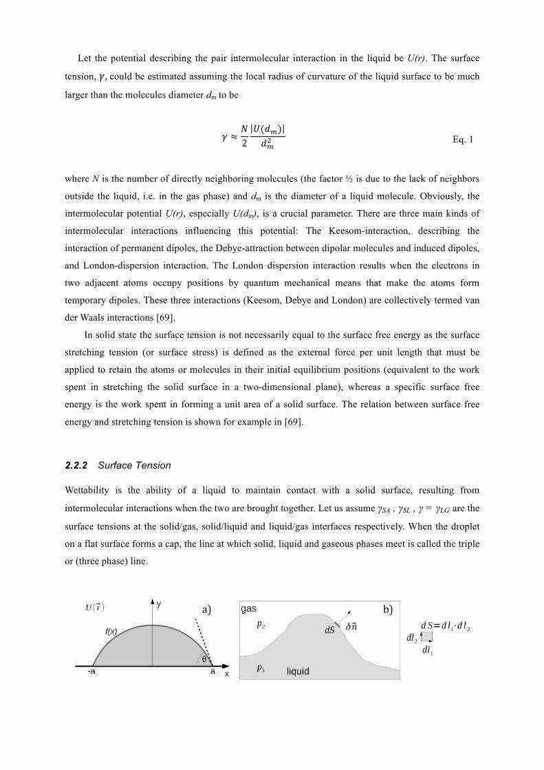
Let the potential describing the pair intermolecular interaction in the liquid be U(r). The surface
tension, 𝛾, could be estimated assuming the local radius of curvature of the liquid surface to be much
larger than the molecules diameter dm to be
𝛾 ≈𝑁2𝑈(𝑑!)𝑑!!
Eq. 1
where N is the number of directly neighboring molecules (the factor ½ is due to the lack of neighbors
outside the liquid, i.e. in the gas phase) and dm is the diameter of a liquid molecule. Obviously, the
intermolecular potential U(r), especially U(dm), is a crucial parameter. There are three main kinds of
intermolecular interactions influencing this potential: The Keesom-interaction, describing the
interaction of permanent dipoles, the Debye-attraction between dipolar molecules and induced dipoles,
and London-dispersion interaction. The London dispersion interaction results when the electrons in
two adjacent atoms occupy positions by quantum mechanical means that make the atoms form
temporary dipoles. These three interactions (Keesom, Debye and London) are collectively termed van
der Waals interactions [69].
In solid state the surface tension is not necessarily equal to the surface free energy as the surface
stretching tension (or surface stress) is defined as the external force per unit length that must be
applied to retain the atoms or molecules in their initial equilibrium positions (equivalent to the work
spent in stretching the solid surface in a two-dimensional plane), whereas a specific surface free
energy is the work spent in forming a unit area of a solid surface. The relation between surface free
energy and stretching tension is shown for example in [69].
2.2.2 Surface Tension Wettability is the ability of a liquid to maintain contact with a solid surface, resulting from
intermolecular interactions when the two are brought together. Let us assume γSA , γSL , γ = γLG are the
surface tensions at the solid/gas, solid/liquid and liquid/gas interfaces respectively. When the droplet
on a flat surface forms a cap, the line at which solid, liquid and gaseous phases meet is called the triple
or (three phase) line.
a) b)
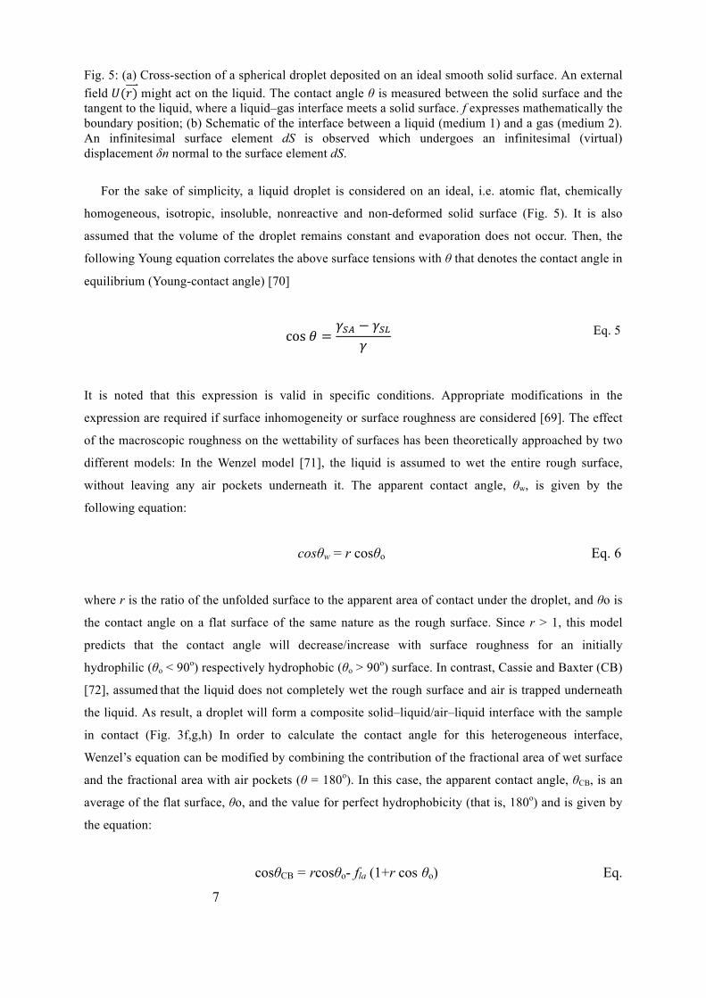
Fig. 5: (a) Cross-section of a spherical droplet deposited on an ideal smooth solid surface. An external field 𝑈(𝑟) might act on the liquid. The contact angle θ is measured between the solid surface and the tangent to the liquid, where a liquid–gas interface meets a solid surface. f expresses mathematically the boundary position; (b) Schematic of the interface between a liquid (medium 1) and a gas (medium 2). An infinitesimal surface element dS is observed which undergoes an infinitesimal (virtual) displacement δn normal to the surface element dS.
For the sake of simplicity, a liquid droplet is considered on an ideal, i.e. atomic flat, chemically
homogeneous, isotropic, insoluble, nonreactive and non-deformed solid surface (Fig. 5). It is also
assumed that the volume of the droplet remains constant and evaporation does not occur. Then, the
following Young equation correlates the above surface tensions with θ that denotes the contact angle in
equilibrium (Young-contact angle) [70]
cos 𝜃 =𝛾!" − 𝛾!"
𝛾 Eq. Eq. 5
It is noted that this expression is valid in specific conditions. Appropriate modifications in the
expression are required if surface inhomogeneity or surface roughness are considered [69]. The effect
of the macroscopic roughness on the wettability of surfaces has been theoretically approached by two
different models: In the Wenzel model [71], the liquid is assumed to wet the entire rough surface,
without leaving any air pockets underneath it. The apparent contact angle, θw, is given by the
following equation:
cosθw = r cosθo Eq. 6
where r is the ratio of the unfolded surface to the apparent area of contact under the droplet, and θo is
the contact angle on a flat surface of the same nature as the rough surface. Since r > 1, this model
predicts that the contact angle will decrease/increase with surface roughness for an initially
hydrophilic (θo < 90o) respectively hydrophobic (θo > 90o) surface. In contrast, Cassie and Baxter (CB)
[72], assumed that the liquid does not completely wet the rough surface and air is trapped underneath
the liquid. As result, a droplet will form a composite solid–liquid/air–liquid interface with the sample
in contact (Fig. 3f,g,h) In order to calculate the contact angle for this heterogeneous interface,
Wenzel’s equation can be modified by combining the contribution of the fractional area of wet surface
and the fractional area with air pockets (θ = 180o). In this case, the apparent contact angle, θCB, is an
average of the flat surface, θo, and the value for perfect hydrophobicity (that is, 180o) and is given by
the equation:
cosθCB = rcosθo- fla (1+r cos θo) Eq.
7
where f la is the fractional flat geometric area of the liquid–air interfaces under the droplet. As fla is
always lower than unity (f la+f ls= 1), this model always predicts enhancement of the hydrophobicity,
independently of the value of the initial contact angle θo. Thus, even for a hydrophilic surface, the
contact angle increases with an increase of fla.
The contact angle hysteresis is another important characteristic of a solid-liquid interface that
determines the self-cleaning properties. When a droplet sits on a tilted surface (Fig. 3b) the contact
angles at the front and back of the droplet correspond to the advancing, θadv, and receding, θrec, contact
angle, respectively. The advancing angle is greater than the receding angle, which results in contact
angle hysteresis occurring due to surface roughness and heterogeneity. Contact angle hysteresis is a
measure of energy dissipation during the flow of a droplet along a solid surface. Surfaces with low
contact angle hysteresis have a very low water roll-off angle, which is the angle to which a surface
must be tilted for a droplet to roll off it. A relationship for contact angle hysteresis as a function of
roughness has been derived, given as[73]:
θadv −θrec = ( fla −1)r
cosθadv,o − cosθrec,o2rcosϑ o +1 Eq. 8
For a homogeneous interface fla = 0, whereas for a composite interface fla is a non-zero number. It is
observed from eq. 7 that, for a homogeneous interface, increasing roughness (high r) leads to
increasing contact angle hysteresis (high values of θadv- θrec), while for a composite interface, an
approach of fla to unity provides both a high contact angle and a low contact angle hysteresis.
Therefore, a heterogeneous interface is desirable for superhydrophobicity and self-cleaning as it
dramatically reduces the area of solid-liquid contact and, therefore, reduces adhesion of a liquid
droplet to the solid surface and contact angle hysteresis.
Formation of a composite interface is a multiscale phenomenon that depends on the relative sizes
of the liquid droplet and roughness details. Such interface is metastable and can be irreversibly
transformed into a homogeneous one, thus damaging superhydrophobicity. Even though it may be
geometrically possible for the system to become heterogeneous, it may be energetically profitable for
the liquid to penetrate into the valleys between asperities and form a homogeneous interface.
Destabilizing factors, such as capillary waves, nanodroplet condensation, surface inhomogeneities and
liquid pressure can be responsible for this transition. It has been demonstrated that the mechanisms
involved into the superhydrophobicity are scale-dependent with effects at various scale ranges acting
simultaneously. Thus, a multiscale, hierarchical, roughness can help to resist the destabilization. High
r can be achieved by both micro- and nano-patterns. For high fla, nano-patterns are desirable because
whether the liquid–air interface is generated depends on the ratio of the distance between two adjacent
asperities and droplet radius. Furthermore, nanoscale asperities can pin the liquid-air interface and thus
prevent liquid from filling the valleys between the micro-asperities even in the case of a hydrophilic
material. Despite numerous experimental and theoretical studies, the effect of the hierarchical
roughness on wettability remains a non-clarified issue and a subject of intense scientific discussions.
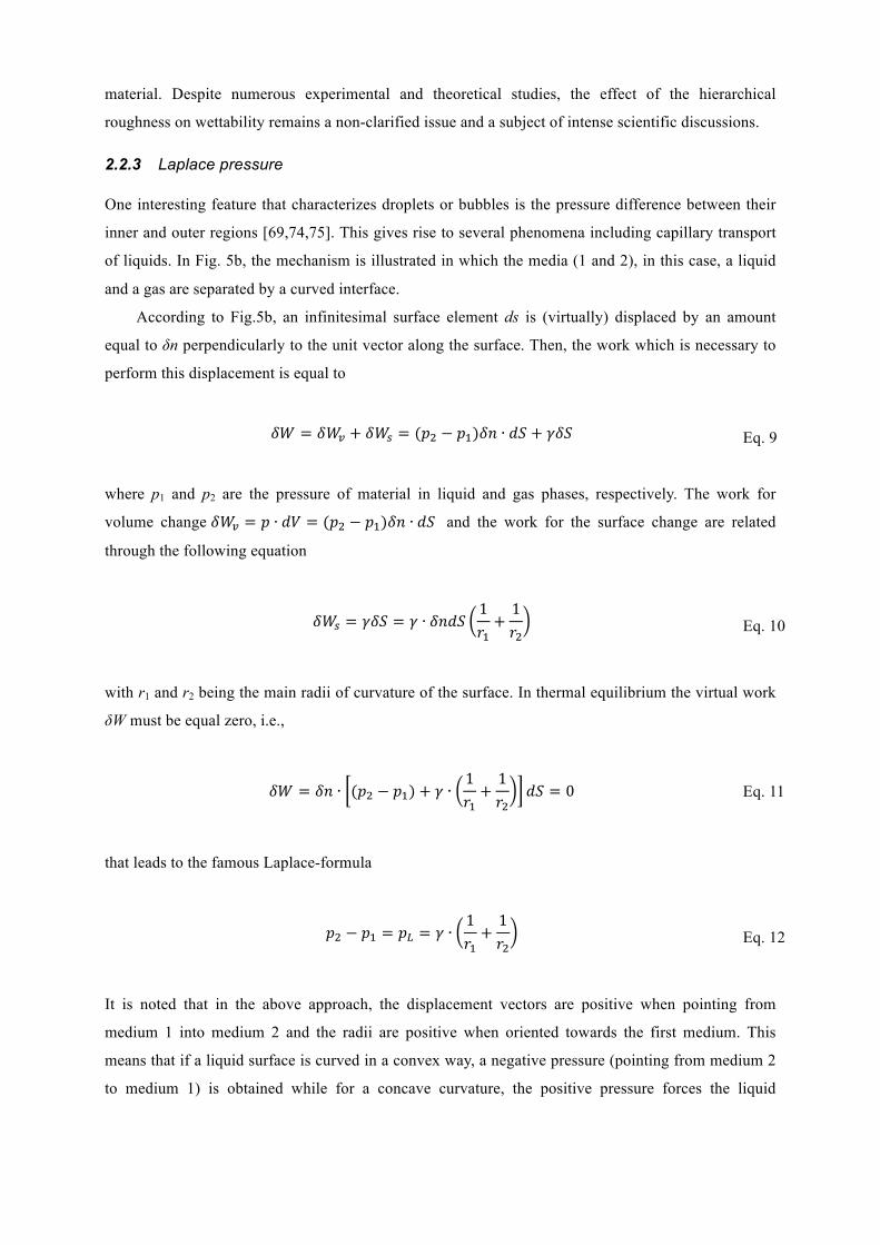
2.2.3 Laplace pressure One interesting feature that characterizes droplets or bubbles is the pressure difference between their
inner and outer regions [69,74,75]. This gives rise to several phenomena including capillary transport
of liquids. In Fig. 5b, the mechanism is illustrated in which the media (1 and 2), in this case, a liquid
and a gas are separated by a curved interface.
According to Fig.5b, an infinitesimal surface element ds is (virtually) displaced by an amount
equal to δn perpendicularly to the unit vector along the surface. Then, the work which is necessary to
perform this displacement is equal to
𝛿𝑊 = 𝛿𝑊! + 𝛿𝑊! = (𝑝! − 𝑝!)𝛿𝑛 ∙ 𝑑𝑆 + 𝛾𝛿𝑆 Eq. 9
where p1 and p2 are the pressure of material in liquid and gas phases, respectively. The work for
volume change 𝛿𝑊! = 𝑝 ∙ 𝑑𝑉 = (𝑝! − 𝑝!)𝛿𝑛 ∙ 𝑑𝑆 and the work for the surface change are related
through the following equation
𝛿𝑊! = 𝛾𝛿𝑆 = 𝛾 ∙ 𝛿𝑛𝑑𝑆1𝑟!+1𝑟!
Eq. 10
with r1 and r2 being the main radii of curvature of the surface. In thermal equilibrium the virtual work
δW must be equal zero, i.e.,
𝛿𝑊 = 𝛿𝑛 ∙ (𝑝! − 𝑝!) + 𝛾 ∙1𝑟!+1𝑟!
𝑑𝑆 = 0 Eq. 11
that leads to the famous Laplace-formula
𝑝! − 𝑝! = 𝑝! = 𝛾 ∙1𝑟!+1𝑟!
Eq. 12
It is noted that in the above approach, the displacement vectors are positive when pointing from
medium 1 into medium 2 and the radii are positive when oriented towards the first medium. This
means that if a liquid surface is curved in a convex way, a negative pressure (pointing from medium 2
to medium 1) is obtained while for a concave curvature, the positive pressure forces the liquid
(medium 1) towards the gas (medium 2). Thus, the Laplace pressure pL is generally working in a way
to flatten the surface if there are no other restrictions.
2.2.4 Capillarity Capillarity (capillary motion, capillary effect, or wicking) [69] is the ability of a liquid to flow in
narrow spaces without the assistance of, or even in opposition to, external forces like gravity. This can
be observed when the combination of surface tension (caused by cohesion within the liquid, leading to
a certain Laplace pressure) and adhesive forces between the liquid and container wall (leading to a
certain contact angle) act in concert to propel the liquid.
2.3 Mechanical
The diverse and often harsh natural habitat populated by many natural organisms has sparked
the need for exceptional mechanical properties required to support their body functions.
Constituent synthetic materials usually have inferior mechanical response, but the clever
combination of materials into composites [76] and the complexity of engineered body patterns
[77] vastly improve its properties of interest which helps species survive and thrive in their
environment.
2.3.1 Wet and dry adhesion
Adhesion is a vital property that a plethora of species require to sustain their body weight
during anchoring and locomotion on a variety of surfaces [78]. Dry adhesion, in nature,
usually involves hierarchical micro- to nanoscale filamentous structures, which decorate many
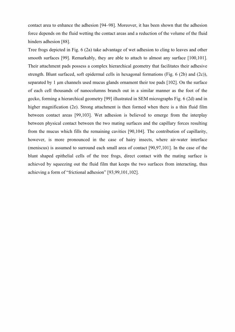
insects and some reptiles enabling them to rapidly climb surfaces. For example, the skin of the
Tokay gecko (Fig. 6 (1a)) is comprised of a complex hierarchical structure of millimeter long
ridges, the lamellae, which are located on its toes and allow compression against rough
surfaces [79]. Extending from the lamellae are micrometer sized, densely packed
(~14.000/mm2), curved hairs called setae [80] (Fig. 6 (1b) and (1c)). Each seta is further
decorated with 100 to 1000 nanometer sized spatulae that emanate from its tip (Fig. 6 (1d)).
The attachment pads on the feet of the Tokay gecko possess a combined area of approximately
220 mm2 where ~3×10! branch out from [81,82]. Eventually, these spatulae reach and adhere
via van der Waals bonds [83] even to rough surfaces since they are able to explore their
geometry. Owing to these intricate multiscale formations and their large numbers, a clinging
ability of approximately 20 N can be reached from the gecko’s pads [78]. The interpretation
of the strong dry adhesion of the geckos is based on the contacts mechanics Johnson-Kendall-
Roberts (JKR) model introduced by [84]. According to this model, the splitting of a single
contact into multiple smaller ones will always result in a stronger overall adhesion. More
specifically, if a seta is considered having a hemispherical tip with radius R, and the adhesion
work per unit area is Wa, then the predicted adhesion force will be:
𝐹! =32𝜋𝑊!𝑅 Eq. 53
According to eq. 13, the adhesion force per contact area (i.e. seta) is proportional its radius. If
a seta’s contact area is divided into a number of smaller and equally sized spatulae n, the
radius of each of the spatulae Rn will be called as 𝑅! =!! (self-similar scaling). Therefore,
the total adhesion force in this case will transform into 𝐹!" = 𝑛𝐹! [85]. However, this model
considers that the adhesion occurs onto flat surfaces, which is not the case in natural surfaces.
On natural rough surfaces the compliance and adaptability of setae are the primary sources of
high adhesion enabling them to conform to the rough surface’s contours and increase contact
[86]. There are also other models developed over the years trying to introduce a saturation in
adhesion force, which is not evident in this model, since the force increases indefinitely for
very large values of n [80].
Tree frogs and some insects on the other hand, make use of wet adhesion where adherence
occurs via a thin film of liquid between contact areas [87]. On insects, wet adhesion can be
attained on both smooth (ants, bees, cockroaches, and grasshoppers) and hairy (beetles, and
flies) pads. Smooth toe pads consist of a dense fibrous material that is soft in compression
while strong in tension. Furthermore, it possesses functional material properties including
adaptability, viscoelasticity, and pressure sensitivity [88,89]. Hairy pads, on the other hand,
are composed of a diverse density of setae which range in length from few micrometers to
several millimeters [89–91]. It has also been reported that the density of the hairs increases
with increasing body weight, thus increasing the number of single contact points and produce
stronger adhesion [85,90,92]. By measuring the single-pad frictional and adhesional forces in
a sample of hairy Gastrophysa viridula and a smooth Carausius morosus pad, it has been
reported that the force per unit pad area was similar between the two configurations and that
both types adhered via a thin liquid film [93]. To sustain this liquid film the hairy pads of
reduviid bugs, flies, coccinellid beetles and chrysomelid beetles secrete fluids directed in the
contact area to enhance the adhesion [94–98]. Moreover, it has been shown that the adhesion
force depends on the fluid wetting the contact areas and a reduction of the volume of the fluid
hinders adhesion [88].
Tree frogs depicted in Fig. 6 (2a) take advantage of wet adhesion to cling to leaves and other
smooth surfaces [99]. Remarkably, they are able to attach to almost any surface [100,101].
Their attachment pads possess a complex hierarchical geometry that facilitates their adhesive
strength. Blunt surfaced, soft epidermal cells in hexagonal formations (Fig. 6 (2b) and (2c)),
separated by 1 µm channels used mucus glands ornament their toe pads [102]. On the surface
of each cell thousands of nanocolumns branch out in a similar manner as the foot of the
gecko, forming a hierarchical geometry [99] illustrated in SEM micrographs Fig. 6 (2d) and in
higher magnification (2e). Strong attachment is then formed when there is a thin fluid film
between contact areas [99,103]. Wet adhesion is believed to emerge from the interplay
between physical contact between the two mating surfaces and the capillary forces resulting
from the mucus which fills the remaining cavities [90,104]. The contribution of capillarity,
however, is more pronounced in the case of hairy insects, where air-water interface
(meniscus) is assumed to surround each small area of contact [90,97,101]. In the case of the
blunt shaped epithelial cells of the tree frogs, direct contact with the mating surface is
achieved by squeezing out the fluid film that keeps the two surfaces from interacting, thus
achieving a form of “frictional adhesion” [93,99,101,102].
Fig. 6: (1a): Close-up photograph of the underside of a gecko's (Gecko gecko) foot as it walks on vertical glass. (1b)-(1d) SEM micrographs of the hierarchical structures on the foot of the gecko that provide it’s supreme adhesion. (1b) and (1c) are different magnifications of rows of setae, (1d) higher magnification SEM image where spatulae can be seen branching from the tip of each seta. ST: seta; SP: spatula; BR: branch. (Image (1a) was adopted from Bjørn Christian Tørrissen / CC BY-SA 3.0. Images (1b), (1c) and (1d) were reproduced with permission from H. Gao et., al [80] Copyright © 2004 Elsevier Ltd. All rights reserved). (2a): Photograph of European tree frog (Hyla arborea). (2b)-(2e) present SEM images of a frog toe pad (2b), with hexagonally aligned epithelial cells (2c) and high magnification of a single hexagonal cell decorated with nanocolumns in (2d). Higher magnification of the nanoculmns is presented in (2e). (Image (2a) provided by Christoph Leeb / CC BY-SA 3.0. Images (2b)-(2e) were taken from [101]. Reprint permission granted from Experimental Biology.)
2.3.2 Friction reduction Friction reduction is of paramount importance in nature, as a means to conserve energy or
protect against abrasion for both land and marine species. Especially for legless reptiles
(snakes and even a few lizard species), but also for other reptiles living in hostile and
challenging tribological environments close to the ground, functional adaptation has
manifested in optimized surface designs and locomotion that is distinguished by economy of
effort [105]. Few examples, like the skin of snakes or the desert lizards Laudakin stoliczkana
and Scincus scinus, show a passive abrasion resistance, which is due to clever material
combination (soft layer beneath a rather hard, but flexible surface) and, in case of the
sandfish, also due to a highly specialized surface chemistry [106–108]. The frictional
performance especially of snakes has been thoroughly investigated and attributed to its ventral
skin [105,108–110] and specific skin formations (scales and structures onto the scales) to
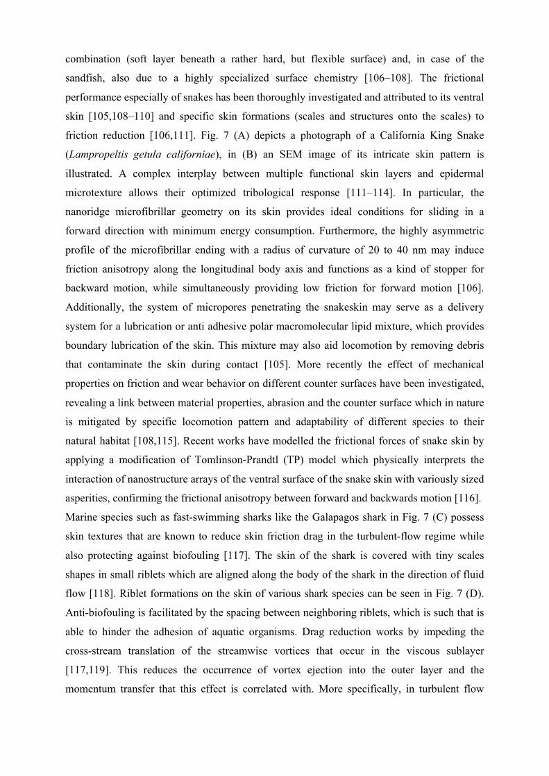
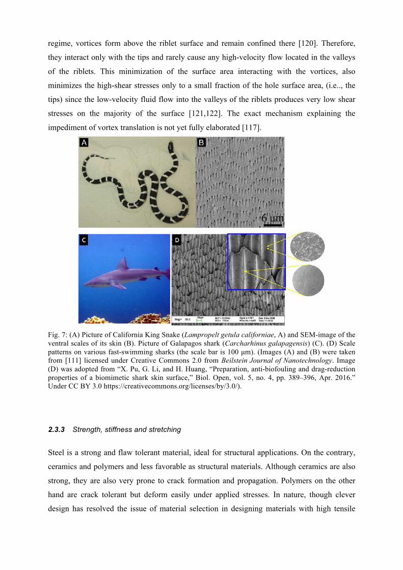
friction reduction [106,111]. Fig. 7 (A) depicts a photograph of a California King Snake
(Lampropeltis getula californiae), in (B) an SEM image of its intricate skin pattern is
illustrated. A complex interplay between multiple functional skin layers and epidermal
microtexture allows their optimized tribological response [111–114]. In particular, the
nanoridge microfibrillar geometry on its skin provides ideal conditions for sliding in a
forward direction with minimum energy consumption. Furthermore, the highly asymmetric
profile of the microfibrillar ending with a radius of curvature of 20 to 40 nm may induce
friction anisotropy along the longitudinal body axis and functions as a kind of stopper for
backward motion, while simultaneously providing low friction for forward motion [106].
Additionally, the system of micropores penetrating the snakeskin may serve as a delivery
system for a lubrication or anti adhesive polar macromolecular lipid mixture, which provides
boundary lubrication of the skin. This mixture may also aid locomotion by removing debris
that contaminate the skin during contact [105]. More recently the effect of mechanical
properties on friction and wear behavior on different counter surfaces have been investigated,
revealing a link between material properties, abrasion and the counter surface which in nature
is mitigated by specific locomotion pattern and adaptability of different species to their
natural habitat [108,115]. Recent works have modelled the frictional forces of snake skin by
applying a modification of Tomlinson-Prandtl (TP) model which physically interprets the
interaction of nanostructure arrays of the ventral surface of the snake skin with variously sized
asperities, confirming the frictional anisotropy between forward and backwards motion [116].
Marine species such as fast-swimming sharks like the Galapagos shark in Fig. 7 (C) possess
skin textures that are known to reduce skin friction drag in the turbulent-flow regime while
also protecting against biofouling [117]. The skin of the shark is covered with tiny scales
shapes in small riblets which are aligned along the body of the shark in the direction of fluid
flow [118]. Riblet formations on the skin of various shark species can be seen in Fig. 7 (D).
Anti-biofouling is facilitated by the spacing between neighboring riblets, which is such that is
able to hinder the adhesion of aquatic organisms. Drag reduction works by impeding the
cross-stream translation of the streamwise vortices that occur in the viscous sublayer
[117,119]. This reduces the occurrence of vortex ejection into the outer layer and the
momentum transfer that this effect is correlated with. More specifically, in turbulent flow
regime, vortices form above the riblet surface and remain confined there [120]. Therefore,
they interact only with the tips and rarely cause any high-velocity flow located in the valleys
of the riblets. This minimization of the surface area interacting with the vortices, also
minimizes the high-shear stresses only to a small fraction of the hole surface area, (i.e.., the
tips) since the low-velocity fluid flow into the valleys of the riblets produces very low shear
stresses on the majority of the surface [121,122]. The exact mechanism explaining the
impediment of vortex translation is not yet fully elaborated [117].
Fig. 7: (A) Picture of California King Snake (Lampropelt getula californiae, A) and SEM-image of the ventral scales of its skin (B). Picture of Galapagos shark (Carcharhinus galapagensis) (C). (D) Scale patterns on various fast-swimming sharks (the scale bar is 100 µm). (Images (A) and (B) were taken from [111] licensed under Creative Commons 2.0 from Beilstein Journal of Nanotechnology. Image (D) was adopted from “X. Pu, G. Li, and H. Huang, “Preparation, anti-biofouling and drag-reduction properties of a biomimetic shark skin surface,” Biol. Open, vol. 5, no. 4, pp. 389–396, Apr. 2016.” Under CC BY 3.0 https://creativecommons.org/licenses/by/3.0/).
2.3.3 Strength, stiffness and stretching
Steel is a strong and flaw tolerant material, ideal for structural applications. On the contrary,
ceramics and polymers and less favorable as structural materials. Although ceramics are also
strong, they are also very prone to crack formation and propagation. Polymers on the other
hand are crack tolerant but deform easily under applied stresses. In nature, though clever
design has resolved the issue of material selection in designing materials with high tensile
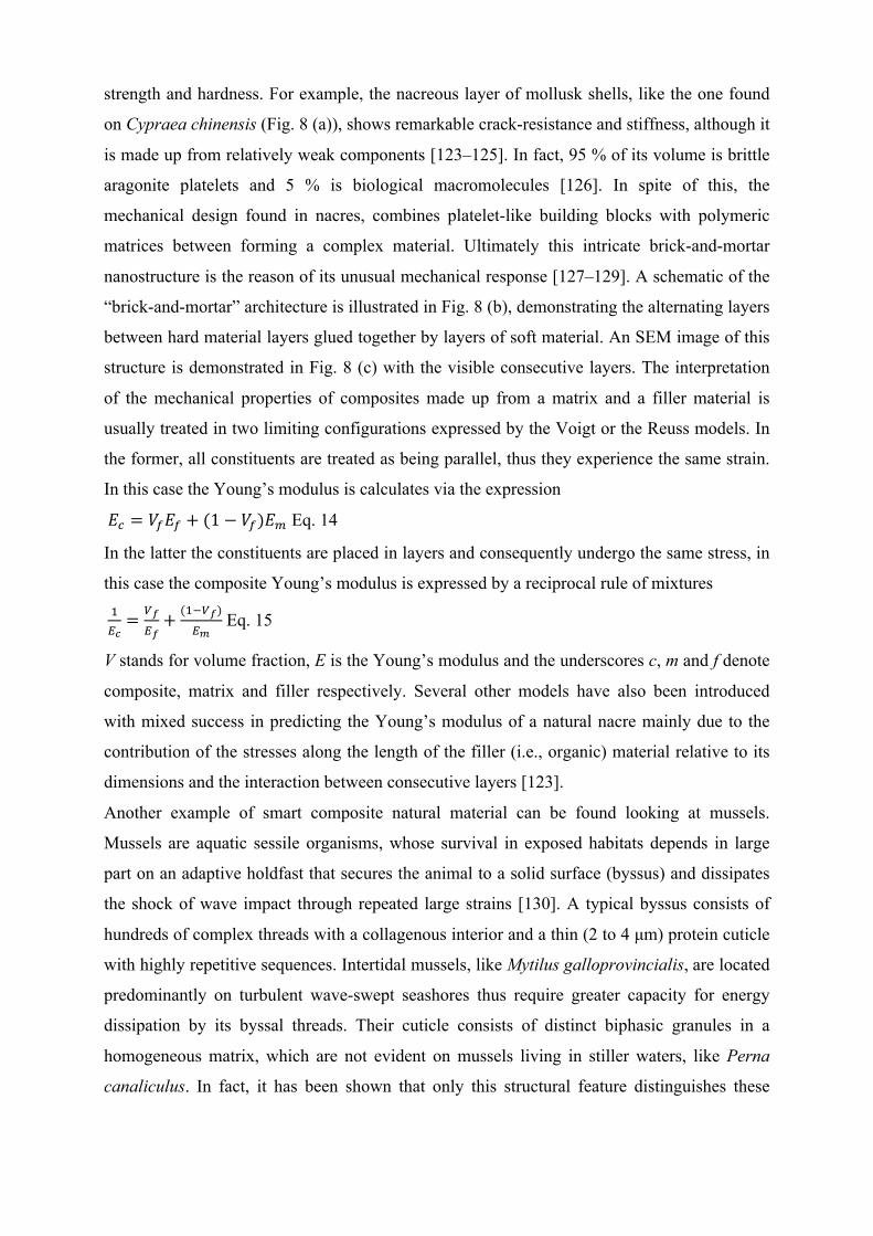
strength and hardness. For example, the nacreous layer of mollusk shells, like the one found
on Cypraea chinensis (Fig. 8 (a)), shows remarkable crack-resistance and stiffness, although it
is made up from relatively weak components [123–125]. In fact, 95 % of its volume is brittle
aragonite platelets and 5 % is biological macromolecules [126]. In spite of this, the
mechanical design found in nacres, combines platelet-like building blocks with polymeric
matrices between forming a complex material. Ultimately this intricate brick-and-mortar
nanostructure is the reason of its unusual mechanical response [127–129]. A schematic of the
“brick-and-mortar” architecture is illustrated in Fig. 8 (b), demonstrating the alternating layers
between hard material layers glued together by layers of soft material. An SEM image of this
structure is demonstrated in Fig. 8 (c) with the visible consecutive layers. The interpretation
of the mechanical properties of composites made up from a matrix and a filler material is
usually treated in two limiting configurations expressed by the Voigt or the Reuss models. In
the former, all constituents are treated as being parallel, thus they experience the same strain.
In this case the Young’s modulus is calculates via the expression
𝐸! = 𝑉!𝐸! + (1− 𝑉!)𝐸! Eq. 14
In the latter the constituents are placed in layers and consequently undergo the same stress, in
this case the composite Young’s modulus is expressed by a reciprocal rule of mixtures
!!!= !!
!!+ (!!!!)
!! Eq. 15
V stands for volume fraction, E is the Young’s modulus and the underscores c, m and f denote
composite, matrix and filler respectively. Several other models have also been introduced
with mixed success in predicting the Young’s modulus of a natural nacre mainly due to the
contribution of the stresses along the length of the filler (i.e., organic) material relative to its
dimensions and the interaction between consecutive layers [123].
Another example of smart composite natural material can be found looking at mussels.
Mussels are aquatic sessile organisms, whose survival in exposed habitats depends in large
part on an adaptive holdfast that secures the animal to a solid surface (byssus) and dissipates
the shock of wave impact through repeated large strains [130]. A typical byssus consists of
hundreds of complex threads with a collagenous interior and a thin (2 to 4 µm) protein cuticle
with highly repetitive sequences. Intertidal mussels, like Mytilus galloprovincialis, are located
predominantly on turbulent wave-swept seashores thus require greater capacity for energy
dissipation by its byssal threads. Their cuticle consists of distinct biphasic granules in a
homogeneous matrix, which are not evident on mussels living in stiller waters, like Perna
canaliculus. In fact, it has been shown that only this structural feature distinguishes these
species. The granules are typically 0.8 µm in diameter and comprise about 50 % of the cuticle
volume. Additionally, they show an intriguing phase-separated morphology with a domain
size of 20 to 40 nm. Strain tests reveal a striking difference between the cuticles of M.
galloprovincialis and P. canaliculus. When the threads of P. canaliculus are stretched 30 %
beyond its length, the cuticle began cracking. The cracks propagated following their
formation through the entire thickness of the cuticle until they were deflected from the
interface with the collagenous core. This exposes the thread core making it prone to microbial
attack and abrasion compromising its performance. On the contrary, stretching the threads of
M. galloprovincialis reveals that cracks first formed within the matrix of the composite cuticle
but did not propagate through the entire cuticle. Cuticle rupture only occurred when strain
levels reached 70 % [130]. This striking difference is due to the existence of the granules,
which seemed to arrest impinging cracks. The eventual cracking manifested when a large
number of microcracks coalesced.
Fig. 8: (a) Cowrie (Cypraea chinensis), a member of small to large marine gastropod mollusks in the family Cypraeidae. (b) Schematic of the microscopic structure of nacre layers with alternating layers of hard aragonite platelets and biological macromolecules. (c) Electron microscopy image of a fractured surface of nacre. (Image (b) was taken from © User:Kebes / Wikimedia Commons / CC-BY-SA-3.0).
2.4 Biological
For numerous applications, surface properties must be sustained to maintain their function. In
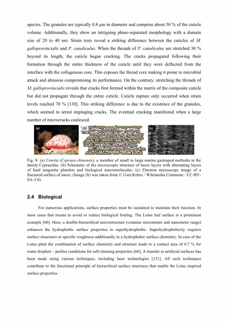
most cases that means to avoid or reduce biological fouling. The Lotus leaf surface is a prominent
example [60]. Here, a double-hierarchical microstructure (contains micrometer and nanometer range)
enhances the hydrophobic surface properties to superhydrophobic. Superhydrophobicity requires
surface structures or specific roughness additionally to a hydrophobic surface chemistry. In case of the
Lotus plant the combination of surface chemistry and structure leads to a contact area of 0.7 % for
water droplets – perfect conditions for self-cleaning properties [66]. A transfer to artificial surfaces has
been made using various techniques, including laser technologies [131]. All such techniques
contribute to the functional principle of hierarchical surface structures that enable the Lotus inspired
surface properties.
2.4.1 Anti-fouling
Turning to the aquatic environment, surfaces in contact with water often undergo fouling
contamination with particles and living organisms [132]. Unwanted fouling contamination may affect
the performance of a surface or other component of a machine. The most prominent examples are the
water vessels where the contamination of their surface reduce their hydrodynamic performance and
cause malfunction to the propulsion system [133,134]. Remarkably, various biological species have
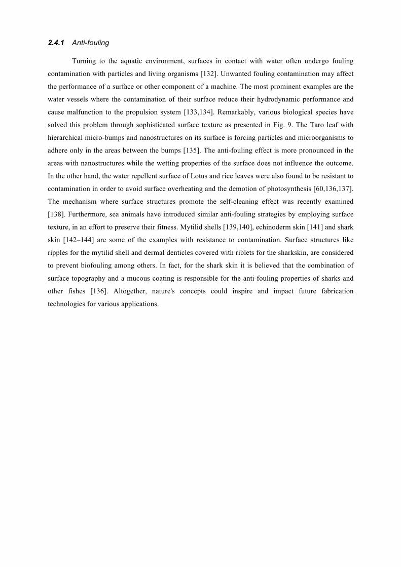
solved this problem through sophisticated surface texture as presented in Fig. 9. The Taro leaf with
hierarchical micro-bumps and nanostructures on its surface is forcing particles and microorganisms to
adhere only in the areas between the bumps [135]. The anti-fouling effect is more pronounced in the
areas with nanostructures while the wetting properties of the surface does not influence the outcome.
In the other hand, the water repellent surface of Lotus and rice leaves were also found to be resistant to
contamination in order to avoid surface overheating and the demotion of photosynthesis [60,136,137].
The mechanism where surface structures promote the self-cleaning effect was recently examined
[138]. Furthermore, sea animals have introduced similar anti-fouling strategies by employing surface
texture, in an effort to preserve their fitness. Mytilid shells [139,140], echinoderm skin [141] and shark
skin [142–144] are some of the examples with resistance to contamination. Surface structures like
ripples for the mytilid shell and dermal denticles covered with riblets for the sharkskin, are considered
to prevent biofouling among others. In fact, for the shark skin it is believed that the combination of
surface topography and a mucous coating is responsible for the anti-fouling properties of sharks and
other fishes [136]. Altogether, nature's concepts could inspire and impact future fabrication
technologies for various applications.
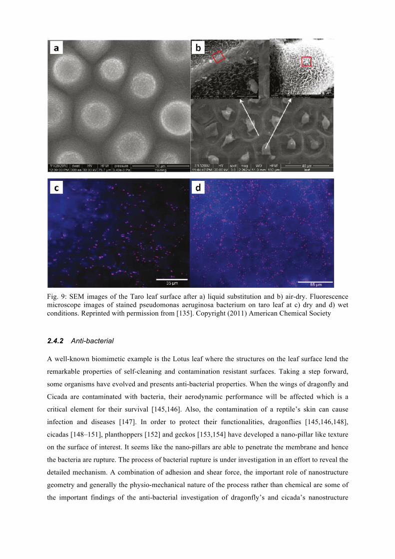
Fig. 9: SEM images of the Taro leaf surface after a) liquid substitution and b) air-dry. Fluorescence microscope images of stained pseudomonas aeruginosa bacterium on taro leaf at c) dry and d) wet conditions. Reprinted with permission from [135]. Copyright (2011) American Chemical Society
2.4.2 Anti-bacterial A well-known biomimetic example is the Lotus leaf where the structures on the leaf surface lend the
remarkable properties of self-cleaning and contamination resistant surfaces. Taking a step forward,
some organisms have evolved and presents anti-bacterial properties. When the wings of dragonfly and
Cicada are contaminated with bacteria, their aerodynamic performance will be affected which is a
critical element for their survival [145,146]. Also, the contamination of a reptile’s skin can cause
infection and diseases [147]. In order to protect their functionalities, dragonflies [145,146,148],
cicadas [148–151], planthoppers [152] and geckos [153,154] have developed a nano-pillar like texture
on the surface of interest. It seems like the nano-pillars are able to penetrate the membrane and hence
the bacteria are rupture. The process of bacterial rupture is under investigation in an effort to reveal the
detailed mechanism. A combination of adhesion and shear force, the important role of nanostructure
geometry and generally the physio-mechanical nature of the process rather than chemical are some of
the important findings of the anti-bacterial investigation of dragonfly’s and cicada’s nanostructure
wings (Fig. 10). Notably, the resistance of bacteria to traditional chemical antibiotic [155] could be
overcome by the physio-mechanical nature of the nanostructure bactericidal properties [156].
Following the great potential of nanotextured surfaces with bactericidal properties, theoretical
calculations have been conducted for an in-depth analysis in an effort to better understand the
mechanism and apply a biomimetic approach to artificial surfaces [157–160]. The main parameters
that affect the bactericidal property of a nanostructure surface have been investigated [157,159,160].
To begin with, the adhesion force is translated to bending and stretching forces on the membrane of
the bacterial. The biochemical properties of the surface can tune the amount of adhesion force [161].
In the case of a nanostructure surface, the adhesion force leads to higher stretching and bending values
due to the increase of the contact area compared to flat surfaces. Interestingly, Pogodin et al. suggested
that the membrane is more likely to rupture at the areas between the pillars where the stretching forces
are higher [158]. The bactericidal property of a nanostructure surface strongly depends on the surface
roughness where for instance higher surface roughness produces higher bending and stretching forces.
Besides, the anti-bacterial surfaces of the dragonfly and the cicada are tailored with structures at least
10 times larger than the bacterial membrane. The membranes of different bacteria have different
stretching modulus and thus can handle the respective amount of stretching and bending forces.
Consequently, membranes with lower stretching modulus are more vulnerable to rupture on a
nanostructure surface [158]. Additionally, the mechanical properties of bacterial membrane change
depending on the environmental conditions [162].
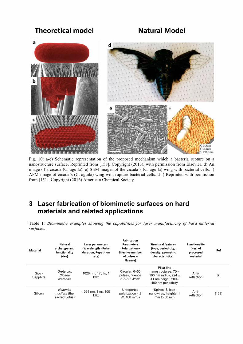
Fig. 10: a-c) Schematic representation of the proposed mechanism which a bacteria rupture on a nanostructure surface. Reprinted from [158], Copyright (2013), with permission from Elsevier. d) An image of a cicada (C. aguila). e) SEM images of the cicada’s (C. aguila) wing with bacterial cells. f) AFM image of cicada’s (C. aguila) wing with rupture bacterial cells. d-f) Reprinted with permission from [151]. Copyright (2016) American Chemical Society.
3 Laser fabrication of biomimetic surfaces on hard materials and related applications
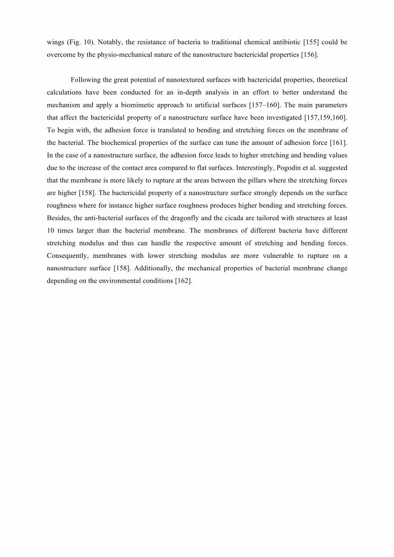
Table 1: Biomimetic examples showing the capabilities for laser manufacturing of hard material surfaces.
Material
Naturalarchetypeandfunctionality
(-ies)
Laserparameters (Wavelength-Pulseduration,Repetition
rate)
FabricationParameters
(Polarization–Effectivenumber
ofpulses–Fluence)
Structuralfeatures(type,periodicity,density,geometriccharacteristics)
Functionality (-ies)of
processedmaterial
Ref
Sio2 - Sapphire
Greta oto, Cicada
cretensis
1026 nm, 170 fs, 1 kHz
Circular, 6–50 pulses, fluence 5.7–8.3 J/cm2
Pillar-like nanostructures, 70 – 100 nm radius, 224 ± 41 nm height, 200–400 nm periodicity
Anti-reflection [7]
Silicon Nelumbo
nucifera (the sacred Lotus)
1064 nm, 1 ns, 100 kHz
Unreported polarization 4.2 W, 100 mm/s
Spikes, Silicon nanowires, heights: 1
mm to 30 mm
Anti-reflection [163]
Silicon Nelumbo
nucifera (the sacred Lotus)
800 nm, 180 fs, 1 kHz
Linearly polarized, 300 to
3000 pulses, fluence = 0.37 to
2.47 J/cm2,
Spikes 10 nm size and aspect ratio of ~
4
Water repellency
[164,165]
Steel alloy
Dysodius lunatus, Texas
horned lizard, Phyton
regius snake, Western
diamondback snake
1030 nm, 340 fs, 1 kHz – 2 MHz
Linear polarization, 0.12
J/cm2, Neff: 150000
ripples, grooves, spikes
Water repellency
[166]
Nickel Shark skin 1026 nm, 170 fs, 1 kHz,
Linear, radial and azimuthal
polarization, Pulse energy: 2.4 mJ, Neff=36 - 207
Complex ripples, Period ~1µm, Dual scale hierarchical
structures, Ripples 615 nm period
Water repellency, iridescence
[167]
Aluminum Nelumbo
nucifera (the sacred Lotus)
355 nm, several ns, 100 kHz
2.8 J/cm2, Unknown
polarization, Unknown
effective No. of pulses
Line and grid texturing with 10µm, 15 µm, 20 µm and 25 µm spacing, Ripples,
Grooves, Spikes
Water repellency [168]
Magnesium alloy
Petal of red rose
Ct-200ii engraving machine
Unknown parameters
Nanoscale flakes, flower like
microstructures 100 nm – 1 µm.
Water repellency, corrosion resistance
[169]
Copper
Morpho Butterfly,
Trogonopterabrookiana
800 nm, 100 fs, 1 kHz, 1064 nm, 1 µs,
30 kHz
Linear polarization,
Pulse energy: 2.4mJ, Unknown
No. Of pulses
Ripples 615 nm period
Hydrophobicity, structural
coloring [170]
Steel alloy
Dysodius magnus,
Texas horned lizard
1) 790 nm, 0.03 ps, 1 kHz
2) 532 nm, 9 ps, 1000 kHz
3) 1026 nm,0.17 ps, 1 kHz
4) 1030 nm, 0.5 ps, 10-1000 kHz
Linear polarization,
Fluence: 0.15 – 2.5 J/cm2, Neff: 5
- 1200
Ripples, rooves, spikes, line scanning
with spacing 20 – 100 µm
Corrosion resistance,
hydrophobicity,
unidirectional fluid
transport
[64,171]
100Cr6 steel, Al2O3
Snakes and Sand fish
lizards
1064 nm, 2 µs, 41 kHz,
11 W, unknown polarization and
number of pulses
Scale-like structures, 13 and 150 µm scale diameter, 6 ± 1 µm
height
Friction reduction [172]
100Cr6 steel Snake Phyton regius
1064 nm, 1µs, 30 kHz
Unknown parameters
Scale-like structures, lateral size 50 µm, 5
µm height
Friction reduction [173]
Stainless steel
Nelumbo nucifera (the sacred Lotus)
355 nm, 25ns, 6.8 Hz
6.7 & 18 mJ/mm2, 146 J/cm2, unknown polarization, pulse overlapping from 20 – 80%
Line scanning with spacing 20 – 100µm
Corrosion resistance,
hydrophobicity
[174]
Silicon Nelumbo
nucifera (the sacred Lotus)
1026 nm, 170 fs, 1 kHz
Linearly polarized, 300 to
3000 pulses, fluence = 0.73
J/cm2, 50 W, 500 mm/s scanning
speed.
Spikes, 6.5 – 14.2 µm height, 2.1 – 2.3
roughness ratios, round humps r = 50
µm, square protuberance L =50 µm, mountain range-like structures L =50
µm; covered by nano-scale mastoid
Corrosion resistance,
hydrophilicity [175]
structure
Graphite cast iron Dung beetles 1064 nm, 5 ms, 14
Hz
Fluence 25, 75, 125 and 175
J/cm2,
Microstructures, depth 0.141 - 0.389 mm, width 0.568 -
1.023 mm, hierarchical
structures. Spikes of 10-20 µm size and
~200 nm undulation onto spikes
Wear resistance [176]
H13 steel Dung beetle, tree leaf 1060 nm, 6 ms, 4 Hz
146 J/cm2, unknown
polarization, unknown number
of pulses
Spikes with 20 - 40 µm period, ripples with 0.5 - 0.9 µm
period (linear). Nano-pillars with 0.8 – 1.3
µm period (azimuthal)random micro structuring
Mechanical/ mechanical/
fatigue resistance
[177,178]
Aluminum alloy
Nelumbo nucifera (the
sacred Lotus), rose petals, water
striders, butterfly wings
520 nm, 380 fs, 200 ns, 20 kHz
50 W, 500 mm/s scanning speed.
Round humps r=50 µm, square
protuberance L=50 µm, mountain range-like structures L=50
µm; covered by nano-scale mastoid
structure
Anti-icing [179]
Titanium Nelumbo
nucifera (the sacred Lotus)
800 nm, 50 fs, 1 kHz Circular
polarization, 20-100 J/cm2
Hierarchical structures. Spikes of 10-20 µm size and
~200 nm undulation onto spikes
Bactericidal [180]
316 L stainless
steel
Nelumbo nucifera (the sacred Lotus)
1030 nm, 350 fs, 1 MHz, 250 kHz
Linear (20.2 – 1910 J/cm2),
Azimuthal (12.2 J/cm2)
Spikes with 20 - 40 µm period, ripples with 0.5 - 0.9 µm period (Linear).
Nano-pillars with 0.8 – 1.3 µm period
(Azimuthal) Ripples, microgratings multi-scale hierarchical
structures
Bactericidal [181]
Pyrex Namib desert beetle
520 nm, 380 fs, 200 kHz, 1032 nm, 310
fs, 1 MHz
Linear, 2.1 - 6.2 J/cm2, unknown
number of pulses
Double-hierarchical surface structures
with 16 µm hatching distance
Fog collection [182]
Titanium Cactus,
Namib desert beetles
1030 nm, 800 fs, 400 kHz
Unknown parameters
Hierarchical micro/nanostructures
Water-collection [183]
Zns Structural color of
butterflies
800 nm, 100 fs, 1‒1000 Hz kHz
Linearly polarized, 0.16 –
1 mJ/cm2
Ripples, microgratings multi-scale hierarchical
structure, Low, medium, high aspect ratio Spikes, Density:
~2.5-9.5x10⁶/cm2, Height: 1.2-8.6 µm, Period: 2.3-6.5µm
Iridescence, water
repellency [184]
Titanium alloy (ti-6al-
4v), stainless steel (x6cr17)
Collembola 1032 nm, 310 fs, 1 MHz
Circular polarization, 54-100 mJ/cm2 118 – 147 number of
pulses
Triangular LIPSS Uniform iridescence [185]
Aluminum Argyroneta aquatic 800 nm, 65 fs 1 kHz
Linear polarization, 0.8
mJ, 1 mm/s,
Line scans, 100 µm spacing
Water repellency [186]
Silicon316 L stainless
steel
Nelumbo nucifera (the sacred Lotus)
Pangolin
800 nm, 150 fs, 1 kHz1, 070 nm, 500
µs, 1 kHz
0.68 -1.50Linear polarization,
Fluence 2000 to 20000 J/cm2,
Linearly polarized
Low, medium, high aspect ratio Spikes,
Density: ~2.5-9.5x10⁶/cm2, Height: 1.2-8.6 µm, Period:
2.3-6.5µm, Overlapping
microdots with micro-riblets
Friction reduction,
anti-adhesion, Neuronal outgrowth
[187,188]
Aluminum alloy, Silicon
Structural complexity of
tissues (extracellular matrix), Leaf with venation
network
1080 nm, 800 nm, 150 fs, 1 kHz,
and 12 ns, 532 nm,
Linear polarization,
Fluence 0.20 to 0.97 J/cm2, Polarization
Ripples 146 nm periodicity, grooves
152 – 146 nm periodicity and 2.4 –
11 µm height, fs-laser irradiation,
followed by hydrophobic
chemical surface modification followed
by ns-laser processing of
venation network
Tissue engineering,
Water transport
[189,190]
Silicon
Nelumbo nucifera (the sacred lotus), Cicada orni,
Rhinotermitidae
800 nm, 150 fs, 1 kHz
Linear Polarization, 500 pulses, Fluence
0.34 to 0.69 J/cm2
Spikes, aspect ratio 2.6 – 6.9
Tissue Engineering [191]
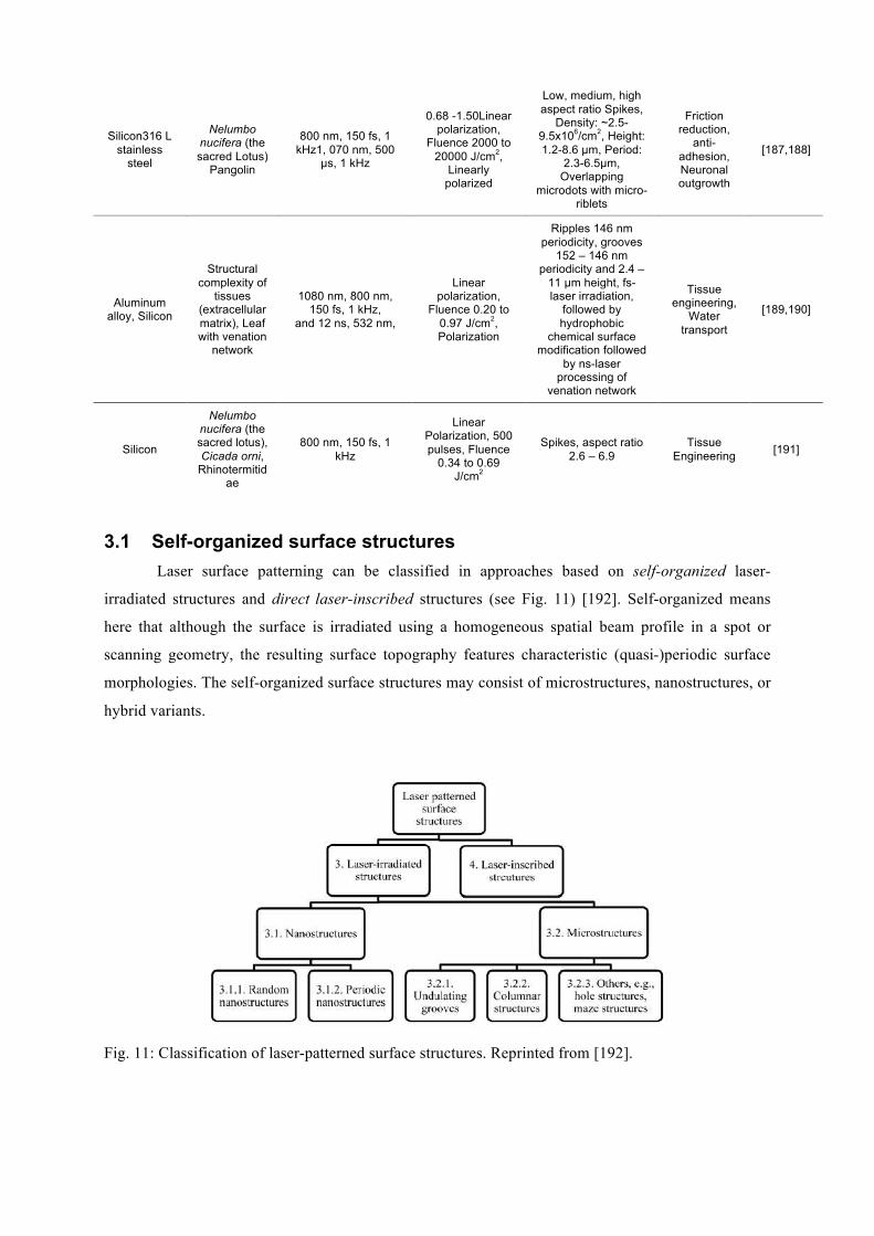
3.1 Self-organized surface structures Laser surface patterning can be classified in approaches based on self-organized laser-
irradiated structures and direct laser-inscribed structures (see Fig. 11) [192]. Self-organized means
here that although the surface is irradiated using a homogeneous spatial beam profile in a spot or
scanning geometry, the resulting surface topography features characteristic (quasi-)periodic surface
morphologies. The self-organized surface structures may consist of microstructures, nanostructures, or
hybrid variants.
Fig. 11: Classification of laser-patterned surface structures. Reprinted from [192].
The periodic self-organized surface structures are usually classified as nanometric laser-
induced periodic surface structures (LIPSS, ripples), and micrometric grooves and spikes (Fig. 12).
Ripples are observed as high spatial frequency LIPSS (HSFL, Fig. 12(a)) featuring periods
significantly smaller than the irradiation wavelength (Λ < λ/2) or as low spatial frequency LIPSS
(LSFL, Fig. 12(b)) showing periods of the order of the laser wavelength [193–195]. Additionally,
grooves (Fig. 12(c)) as transitory morphology between LIPSS and micrometric spikes (Fig. 12(d)) are
seen. LIPSS and grooves structures were not only observed in conductive and semiconductor
materials, but also in dielectrics [196,197]. LIPSS and grooves show a well-defined orientation with
respect to a linear polarization state of the incident laser light and are distorted or even absent for other
polarization states. All these different structures resemble surface morphologies found in nature and,
therefore, can be considered as “biomimetic” [198–202].
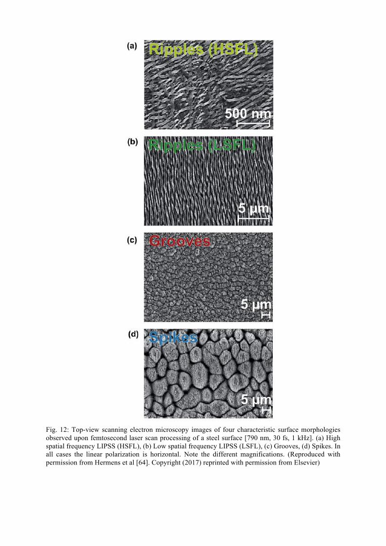
Fig. 12: Top-view scanning electron microscopy images of four characteristic surface morphologies observed upon femtosecond laser scan processing of a steel surface [790 nm, 30 fs, 1 kHz]. (a) High spatial frequency LIPSS (HSFL), (b) Low spatial frequency LIPSS (LSFL), (c) Grooves, (d) Spikes. In all cases the linear polarization is horizontal. Note the different magnifications. (Reproduced with permission from Hermens et al [64]. Copyright (2017) reprinted with permission from Elsevier)
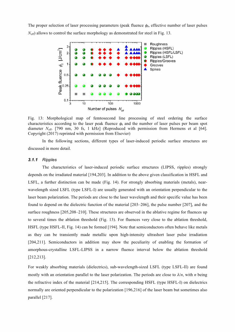
The proper selection of laser processing parameters (peak fluence φ0, effective number of laser pulses
Neff) allows to control the surface morphology as demonstrated for steel in Fig. 13.
Fig. 13: Morphological map of femtosecond line processing of steel ordering the surface characteristics according to the laser peak fluence φ0 and the number of laser pulses per beam spot diameter Neff. [790 nm, 30 fs, 1 kHz] (Reproduced with permission from Hermens et al [64]. Copyright (2017) reprinted with permission from Elsevier)
In the following sections, different types of laser-induced periodic surface structures are
discussed in more detail.
3.1.1 Ripples
The characteristics of laser-induced periodic surface structures (LIPSS, ripples) strongly
depends on the irradiated material [194,203]. In addition to the above given classification in HSFL and
LSFL, a further distinction can be made (Fig. 14). For strongly absorbing materials (metals), near-
wavelength sized LSFL (type LSFL-I) are usually generated with an orientation perpendicular to the
laser beam polarization. The periods are close to the laser wavelength and their specific value has been
found to depend on the dielectric function of the material [203–206], the pulse number [207], and the
surface roughness [205,208–210]. These structures are observed in the ablative regime for fluences up
to several times the ablation threshold (Fig. 13). For fluences very close to the ablation threshold,
HSFL (type HSFL-II, Fig. 14) can be formed [194]. Note that semiconductors often behave like metals
as they can be transiently made metallic upon high-intensity ultrashort laser pulse irradiation
[204,211]. Semiconductors in addition may show the peculiarity of enabling the formation of
amorphous-crystalline LSFL-LIPSS in a narrow fluence interval below the ablation threshold
[212,213].
For weakly absorbing materials (dielectrics), sub-wavelength-sized LSFL (type LSFL-II) are found
mostly with an orientation parallel to the laser polarization. The periods are close to λ/n, with n being
the refractive index of the material [214,215]. The corresponding HSFL (type HSFL-I) on dielectrics
normally are oriented perpendicular to the polarization [196,216] of the laser beam but sometimes also
parallel [217].
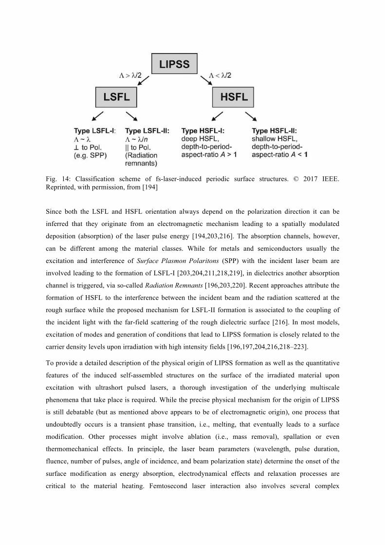
Fig. 14: Classification scheme of fs-laser-induced periodic surface structures. © 2017 IEEE. Reprinted, with permission, from [194]
Since both the LSFL and HSFL orientation always depend on the polarization direction it can be
inferred that they originate from an electromagnetic mechanism leading to a spatially modulated
deposition (absorption) of the laser pulse energy [194,203,216]. The absorption channels, however,
can be different among the material classes. While for metals and semiconductors usually the
excitation and interference of Surface Plasmon Polaritons (SPP) with the incident laser beam are
involved leading to the formation of LSFL-I [203,204,211,218,219], in dielectrics another absorption
channel is triggered, via so-called Radiation Remnants [196,203,220]. Recent approaches attribute the
formation of HSFL to the interference between the incident beam and the radiation scattered at the
rough surface while the proposed mechanism for LSFL-II formation is associated to the coupling of
the incident light with the far-field scattering of the rough dielectric surface [216]. In most models,
excitation of modes and generation of conditions that lead to LIPSS formation is closely related to the
carrier density levels upon irradiation with high intensity fields [196,197,204,216,218–223].
To provide a detailed description of the physical origin of LIPSS formation as well as the quantitative
features of the induced self-assembled structures on the surface of the irradiated material upon
excitation with ultrashort pulsed lasers, a thorough investigation of the underlying multiscale
phenomena that take place is required. While the precise physical mechanism for the origin of LIPSS
is still debatable (but as mentioned above appears to be of electromagnetic origin), one process that
undoubtedly occurs is a transient phase transition, i.e., melting, that eventually leads to a surface
modification. Other processes might involve ablation (i.e., mass removal), spallation or even
thermomechanical effects. In principle, the laser beam parameters (wavelength, pulse duration,
fluence, number of pulses, angle of incidence, and beam polarization state) determine the onset of the
surface modification as energy absorption, electrodynamical effects and relaxation processes are
critical to the material heating. Femtosecond laser interaction also involves several complex
phenomena, including energy absorption, photo-ionization processes, electron excitation and electron-
relaxation processes.
Various theoretical approaches or experimental observations were performed in a variety of conditions
to describe the evolution of the surface morphology and LIPSS formation. One approach was based on
Kuramoto-Sivashinsky that assumed self-organization processes [224], however, the underlying
theoretical approach was not sufficient to correlate the laser conditions with the induced surface
morphological features.
A systematic study to couple lattice thermal response with electrodynamical effects to describe the
formation of LSFL-I assumed firstly the interference of the SPP with the incident beam
[203,204,211,218,225,226] to determine the orientation of the periodic structures. A unified model
[219] comprises: (i) an electromagnetics component that describes SPP excitation and interference
with the incident beam that leads to a periodic modulation of the laser field energy density, (ii) a heat
transfer component that accounts for carrier-lattice thermalization through particle dynamics and heat
conduction and carrier-phonon coupling, and (iii) a hydrodynamics component that describes the
dynamics of the molten material and the subsequent resolidification process assuming an
incompressible Newtonian fluid (melt) flow (Fig. 15a) that includes recoil pressure and surface tension
contributions as well as Marangoni effects and hydrothermal convection. Due to the need for the
consideration of a phase transition for the description of an induced morphological change, fluid
dynamics is introduced. The material that undergoes melting is assumed to be an incompressible
Newtonian fluid and its dynamics is described by the following equations:
(i). for the mass conservation (incompressible fluid):
∇ ∙ 𝑢 = 0 Eq. 6
(ii). for the energy conservation:
𝐶!(!) 𝜕𝑇!
(!)
𝜕𝑡+ ∇ ∙ 𝑢𝑇!
(!) = ∇ ∙ 𝐾!(!)∇𝑇!
(!) +𝐶!𝜏!
𝑇! − 𝑇! Eq. 7
The following Navier-Stokes equation is used to describe the movement of hydrothermal waves
𝜌!(!) 𝜕𝑢
𝜕𝑡+ 𝑢 ∙ ∇𝑢 = ∇ ∙ −𝑃 + 𝜇 ∇𝑢 + 𝜇 ∇𝑢
! Eq. 8
where ur is the velocity of the fluid, µ is the liquid viscosity, P is the total pressure (hydrodynamical
and recoil) and ( )mLC stands for the heat capacity of the liquid phase. K(m)
L stands for the heat
conductivity of the molten material while Cc is the heat capacity of carrier subsystem. Finally, TC, TL,
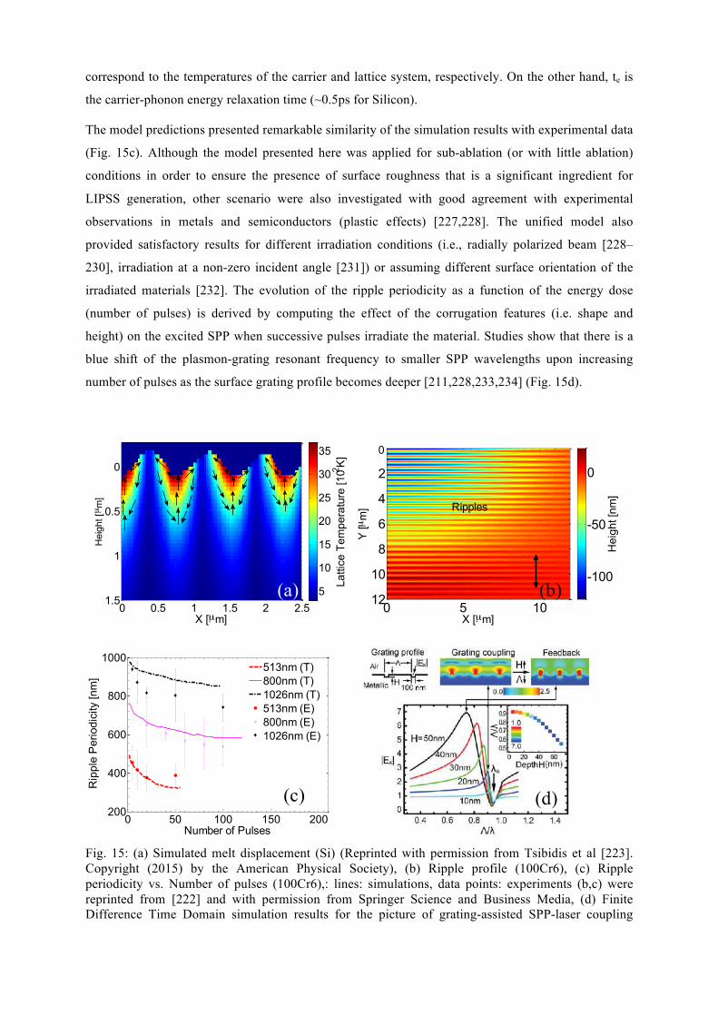
correspond to the temperatures of the carrier and lattice system, respectively. On the other hand, te is
the carrier-phonon energy relaxation time (~0.5ps for Silicon).
The model predictions presented remarkable similarity of the simulation results with experimental data
(Fig. 15c). Although the model presented here was applied for sub-ablation (or with little ablation)
conditions in order to ensure the presence of surface roughness that is a significant ingredient for
LIPSS generation, other scenario were also investigated with good agreement with experimental
observations in metals and semiconductors (plastic effects) [227,228]. The unified model also
provided satisfactory results for different irradiation conditions (i.e., radially polarized beam [228–
230], irradiation at a non-zero incident angle [231]) or assuming different surface orientation of the
irradiated materials [232]. The evolution of the ripple periodicity as a function of the energy dose
(number of pulses) is derived by computing the effect of the corrugation features (i.e. shape and
height) on the excited SPP when successive pulses irradiate the material. Studies show that there is a
blue shift of the plasmon-grating resonant frequency to smaller SPP wavelengths upon increasing
number of pulses as the surface grating profile becomes deeper [211,228,233,234] (Fig. 15d).
Fig. 15: (a) Simulated melt displacement (Si) (Reprinted with permission from Tsibidis et al [223]. Copyright (2015) by the American Physical Society), (b) Ripple profile (100Cr6), (c) Ripple periodicity vs. Number of pulses (100Cr6),: lines: simulations, data points: experiments (b,c) were reprinted from [222] and with permission from Springer Science and Business Media, (d) Finite Difference Time Domain simulation results for the picture of grating-assisted SPP-laser coupling
X [µm]
Hei
ght [µ m
]
0 0.5 1 1.5 2 2.5
0
0.5
1
1.5
Latti
ce T
empe
ratu
re [1
02 K]
5
10
15
20
25
30
35
X [µm]
Y [µ
m]
0 5 10
2
4
6
8
10
12H
eigh
t [nm
]
-100
-50
0
0
Ripples
0 50 100 150 200200
400
600
800
1000
Number of Pulses
Rip
ple
Per
iodi
city
[nm
]
513nm (T)800nm (T)1026nm (T)513nm (E)800nm (E)1026nm (E)
(a) (b)
(c) (d)
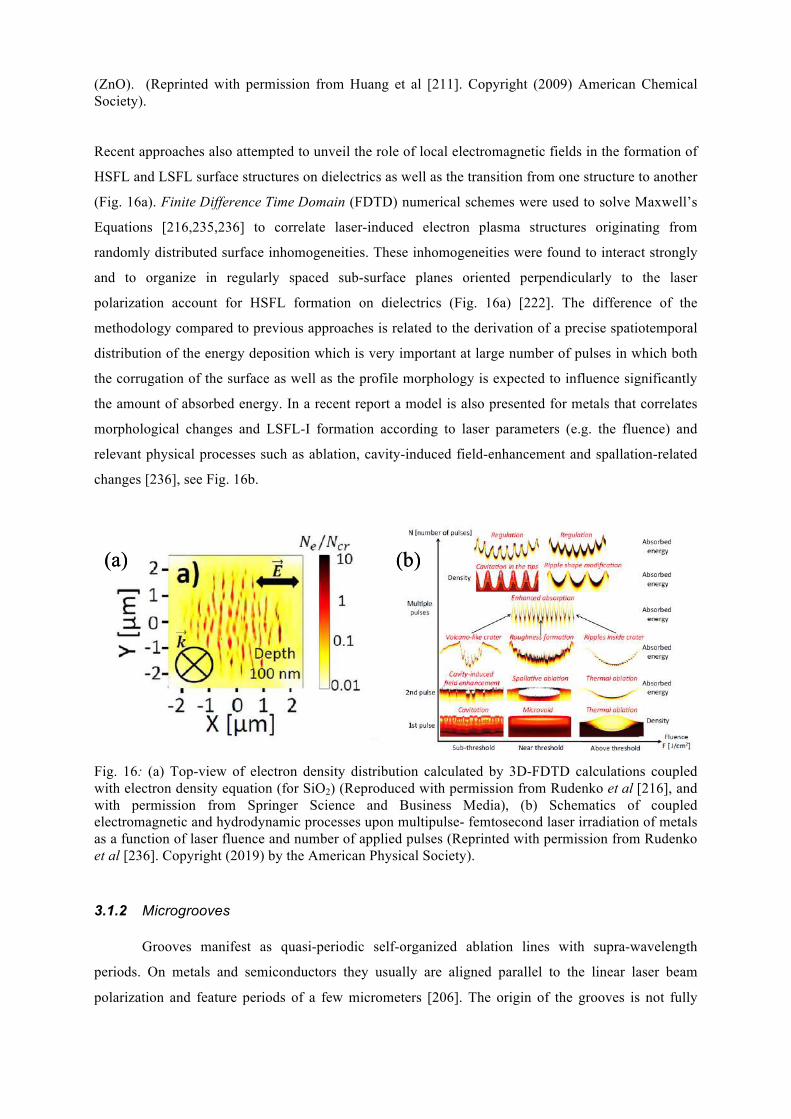
(ZnO). (Reprinted with permission from Huang et al [211]. Copyright (2009) American Chemical Society).
Recent approaches also attempted to unveil the role of local electromagnetic fields in the formation of
HSFL and LSFL surface structures on dielectrics as well as the transition from one structure to another
(Fig. 16a). Finite Difference Time Domain (FDTD) numerical schemes were used to solve Maxwell’s
Equations [216,235,236] to correlate laser-induced electron plasma structures originating from
randomly distributed surface inhomogeneities. These inhomogeneities were found to interact strongly
and to organize in regularly spaced sub-surface planes oriented perpendicularly to the laser
polarization account for HSFL formation on dielectrics (Fig. 16a) [222]. The difference of the
methodology compared to previous approaches is related to the derivation of a precise spatiotemporal
distribution of the energy deposition which is very important at large number of pulses in which both
the corrugation of the surface as well as the profile morphology is expected to influence significantly
the amount of absorbed energy. In a recent report a model is also presented for metals that correlates
morphological changes and LSFL-I formation according to laser parameters (e.g. the fluence) and
relevant physical processes such as ablation, cavity-induced field-enhancement and spallation-related
changes [236], see Fig. 16b.
Fig. 16: (a) Top-view of electron density distribution calculated by 3D-FDTD calculations coupled with electron density equation (for SiO2) (Reproduced with permission from Rudenko et al [216], and with permission from Springer Science and Business Media), (b) Schematics of coupled electromagnetic and hydrodynamic processes upon multipulse- femtosecond laser irradiation of metals as a function of laser fluence and number of applied pulses (Reprinted with permission from Rudenko et al [236]. Copyright (2019) by the American Physical Society).
3.1.2 Microgrooves Grooves manifest as quasi-periodic self-organized ablation lines with supra-wavelength
periods. On metals and semiconductors they usually are aligned parallel to the linear laser beam
polarization and feature periods of a few micrometers [206]. The origin of the grooves is not fully
(a) (b) (a) (b)
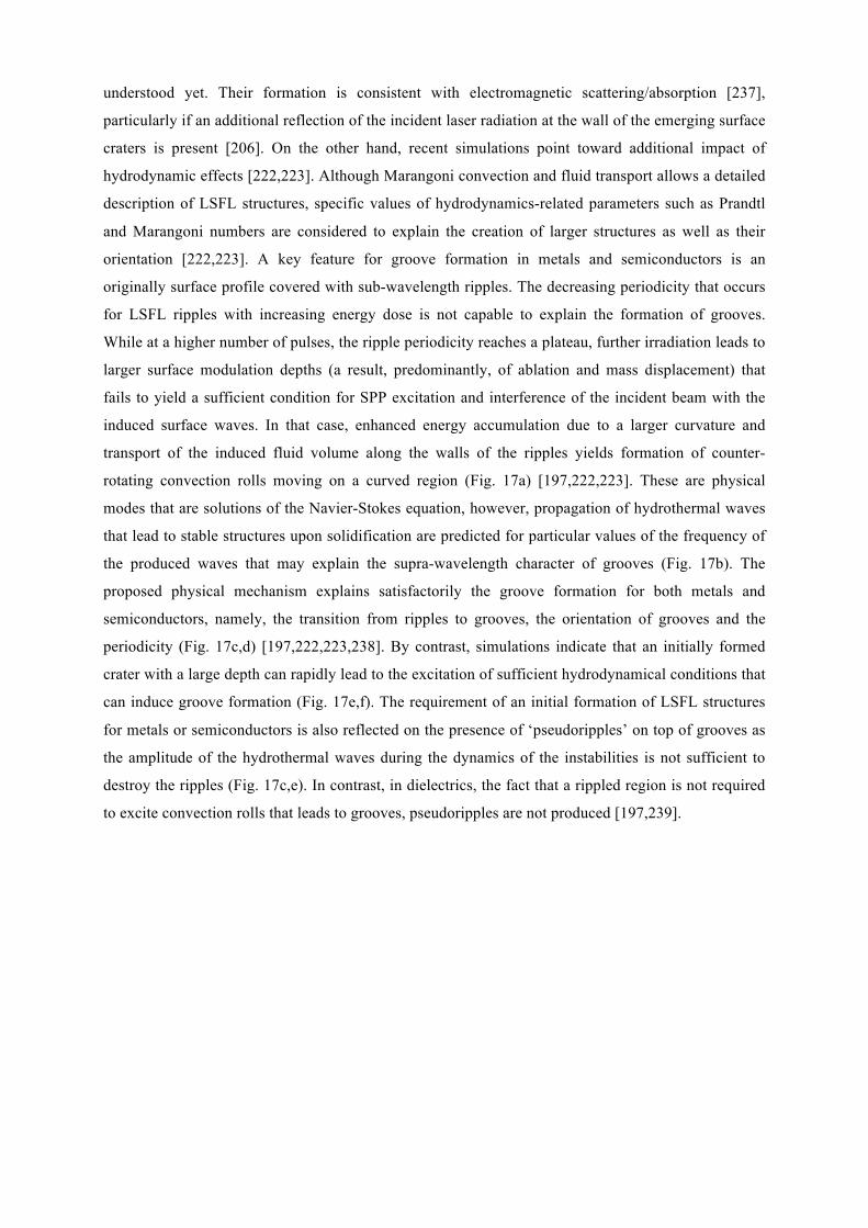
understood yet. Their formation is consistent with electromagnetic scattering/absorption [237],
particularly if an additional reflection of the incident laser radiation at the wall of the emerging surface
craters is present [206]. On the other hand, recent simulations point toward additional impact of
hydrodynamic effects [222,223]. Although Marangoni convection and fluid transport allows a detailed
description of LSFL structures, specific values of hydrodynamics-related parameters such as Prandtl
and Marangoni numbers are considered to explain the creation of larger structures as well as their
orientation [222,223]. A key feature for groove formation in metals and semiconductors is an
originally surface profile covered with sub-wavelength ripples. The decreasing periodicity that occurs
for LSFL ripples with increasing energy dose is not capable to explain the formation of grooves.
While at a higher number of pulses, the ripple periodicity reaches a plateau, further irradiation leads to
larger surface modulation depths (a result, predominantly, of ablation and mass displacement) that
fails to yield a sufficient condition for SPP excitation and interference of the incident beam with the
induced surface waves. In that case, enhanced energy accumulation due to a larger curvature and
transport of the induced fluid volume along the walls of the ripples yields formation of counter-
rotating convection rolls moving on a curved region (Fig. 17a) [197,222,223]. These are physical
modes that are solutions of the Navier-Stokes equation, however, propagation of hydrothermal waves
that lead to stable structures upon solidification are predicted for particular values of the frequency of
the produced waves that may explain the supra-wavelength character of grooves (Fig. 17b). The
proposed physical mechanism explains satisfactorily the groove formation for both metals and
semiconductors, namely, the transition from ripples to grooves, the orientation of grooves and the
periodicity (Fig. 17c,d) [197,222,223,238]. By contrast, simulations indicate that an initially formed
crater with a large depth can rapidly lead to the excitation of sufficient hydrodynamical conditions that
can induce groove formation (Fig. 17e,f). The requirement of an initial formation of LSFL structures
for metals or semiconductors is also reflected on the presence of ‘pseudoripples’ on top of grooves as
the amplitude of the hydrothermal waves during the dynamics of the instabilities is not sufficient to
destroy the ripples (Fig. 17c,e). In contrast, in dielectrics, the fact that a rippled region is not required
to excite convection rolls that leads to grooves, pseudoripples are not produced [197,239].
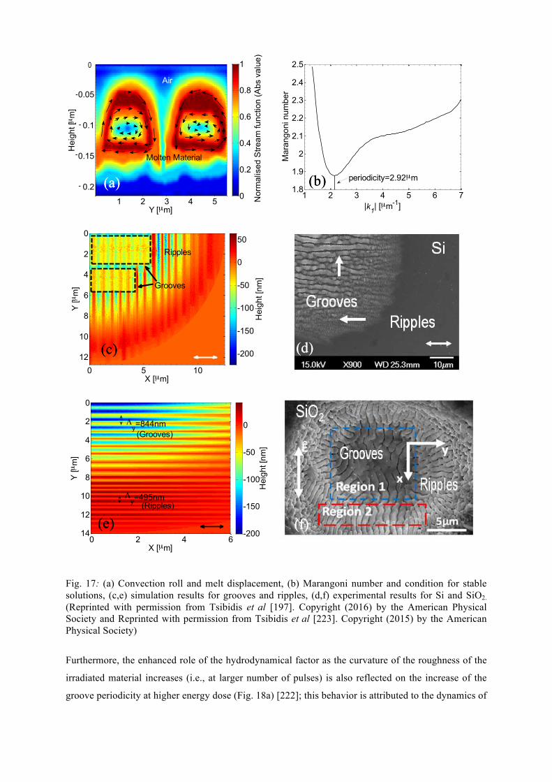
Fig. 17: (a) Convection roll and melt displacement, (b) Marangoni number and condition for stable solutions, (c,e) simulation results for grooves and ripples, (d,f) experimental results for Si and SiO2. (Reprinted with permission from Tsibidis et al [197]. Copyright (2016) by the American Physical Society and Reprinted with permission from Tsibidis et al [223]. Copyright (2015) by the American Physical Society)
Furthermore, the enhanced role of the hydrodynamical factor as the curvature of the roughness of the
irradiated material increases (i.e., at larger number of pulses) is also reflected on the increase of the
groove periodicity at higher energy dose (Fig. 18a) [222]; this behavior is attributed to the dynamics of
Y [µm]
Hei
ght [µ
m]
1 2 3 4 5
0.05
0.1
0.15
0.2
Nor
mal
ised
Stre
am fu
nctio
n (A
bs v
alue
)
0
0.2
0.4
0.6
0.8
1
-
-
-
-
0
Molten Material
Air
1 2 3 4 5 6 71.8
1.9
2
2.1
2.2
2.3
2.4
2.5
|k1| [µm-1]
Mar
ango
ni n
umbe
r
periodicity=2.92µm
X [µm]
Y [µ
m]
0 5 10
0
2
4
6
8
10
12
Hei
ght [
nm]
-200
-150
-100
-50
0
50Ripples
Grooves
X [µm]
Y [µ
m]
0 2 4 6
0
2
4
6
8
10
12
14
Hei
ght [
nm]
-200
-150
-100
-50
0
Λy=495nm
Λy=844nm
(Ripples)
(Grooves)
(a) (b)
(c) (d)
(e) (f)
(a) (b)
(c) (d)
(e) (f)
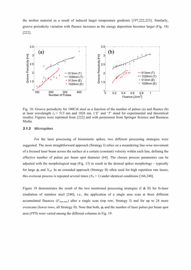
the molten material as a result of induced larger temperature gradients [197,222,223]. Similarly,
groove periodicity variation with fluence increases as the energy deposition becomes larger (Fig. 18)
[222].
Fig. 18: Groove periodicity for 100Cr6 steel as a function of the number of pulses (a) and fluence (b) at laser wavelength λL = 513 nm and 1026 nm. (‘E’ and ‘T’ stand for experimental and theoretical results). Figures were reprinted from [222] and with permission from Springer Science and Business Media
3.1.3 Microspikes For the laser processing of biomimetic spikes, two different processing strategies were
suggested. The most straightforward approach (Strategy I) relies on a meandering line-wise movement
of a focused laser beam across the surface at a certain (constant) velocity within each line, defining the
effective number of pulses per beam spot diameter [64]. The chosen process parameters can be
adjusted with the morphological map (Fig. 13) to result in the desired spikes morphology – typically
for large φ0 and Neff. In an extended approach (Strategy II) often used for high repetition rate lasers,
this overscan process is repeated several times (NS > 1) under identical conditions [166,240].
Figure 19 demonstrates the result of the two mentioned processing strategies (I & II) for fs-laser
irradiation of stainless steel [240], i.e., the application of a single area scan at three different
accumulated fluences (FΣline,max) after a single scan (top row, Strategy I) and for up to 24 more
overscans (lower rows, all Strategy II). Note that both, φ0 and the number of laser pulses per beam spot
area (PPS) were varied among the different columns in Fig. 19.
100 200 300 4001
1.5
2
2.5
3
3.5
Number of Pulses
Gro
ove
Per
iodi
city
[µm
]
513nm (T)1026nm (T)513nm (E)1026nm (E)
0 0.2 0.4 0.6 0.8 11
1.5
2
2.5
3
3.5
Fluence [J/cm2]G
roov
e P
erio
dici
ty [µ
m]
513nm (T)1026nm (T)513nm (E)1026nm (E)
(a) (b) (a) (b)
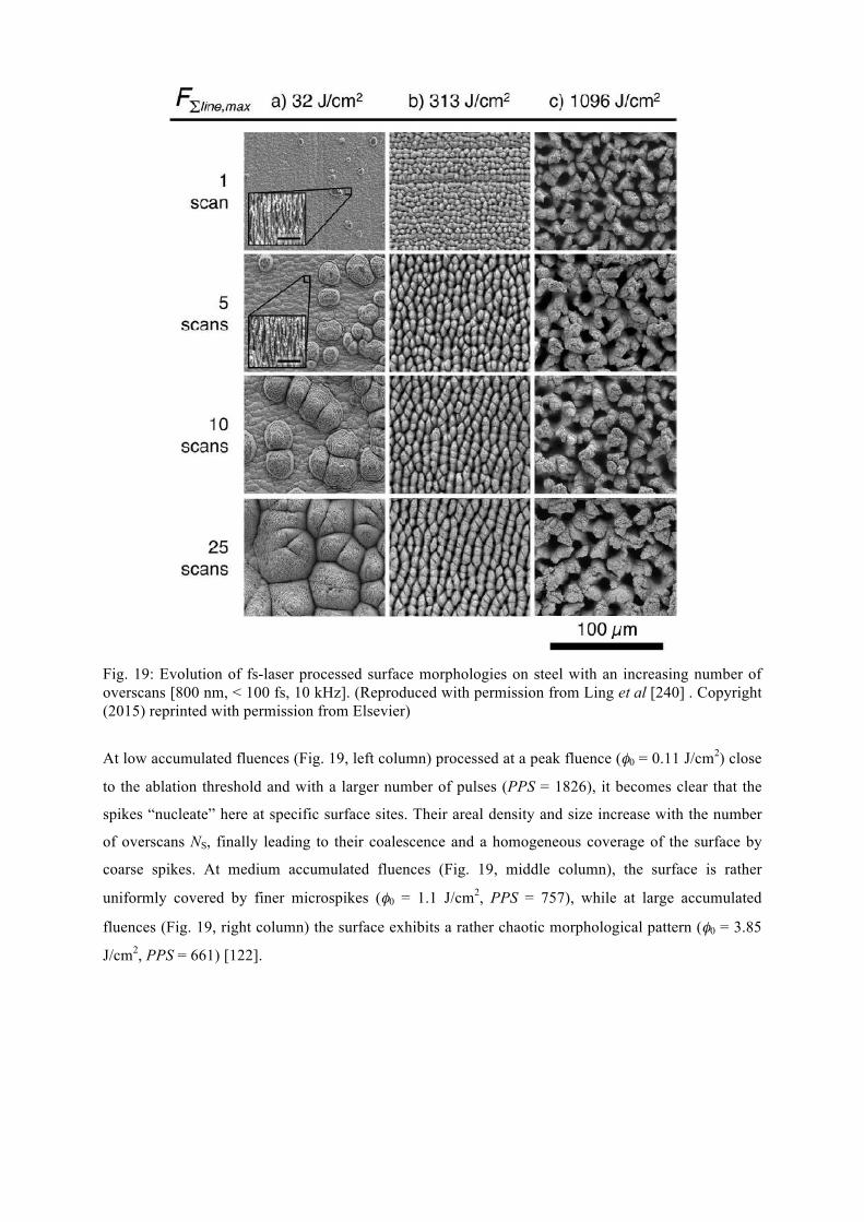
Fig. 19: Evolution of fs-laser processed surface morphologies on steel with an increasing number of overscans [800 nm, < 100 fs, 10 kHz]. (Reproduced with permission from Ling et al [240] . Copyright (2015) reprinted with permission from Elsevier)
At low accumulated fluences (Fig. 19, left column) processed at a peak fluence (φ0 = 0.11 J/cm2) close
to the ablation threshold and with a larger number of pulses (PPS = 1826), it becomes clear that the
spikes “nucleate” here at specific surface sites. Their areal density and size increase with the number
of overscans NS, finally leading to their coalescence and a homogeneous coverage of the surface by
coarse spikes. At medium accumulated fluences (Fig. 19, middle column), the surface is rather
uniformly covered by finer microspikes (φ0 = 1.1 J/cm2, PPS = 757), while at large accumulated
fluences (Fig. 19, right column) the surface exhibits a rather chaotic morphological pattern (φ0 = 3.85
J/cm2, PPS = 661) [122].
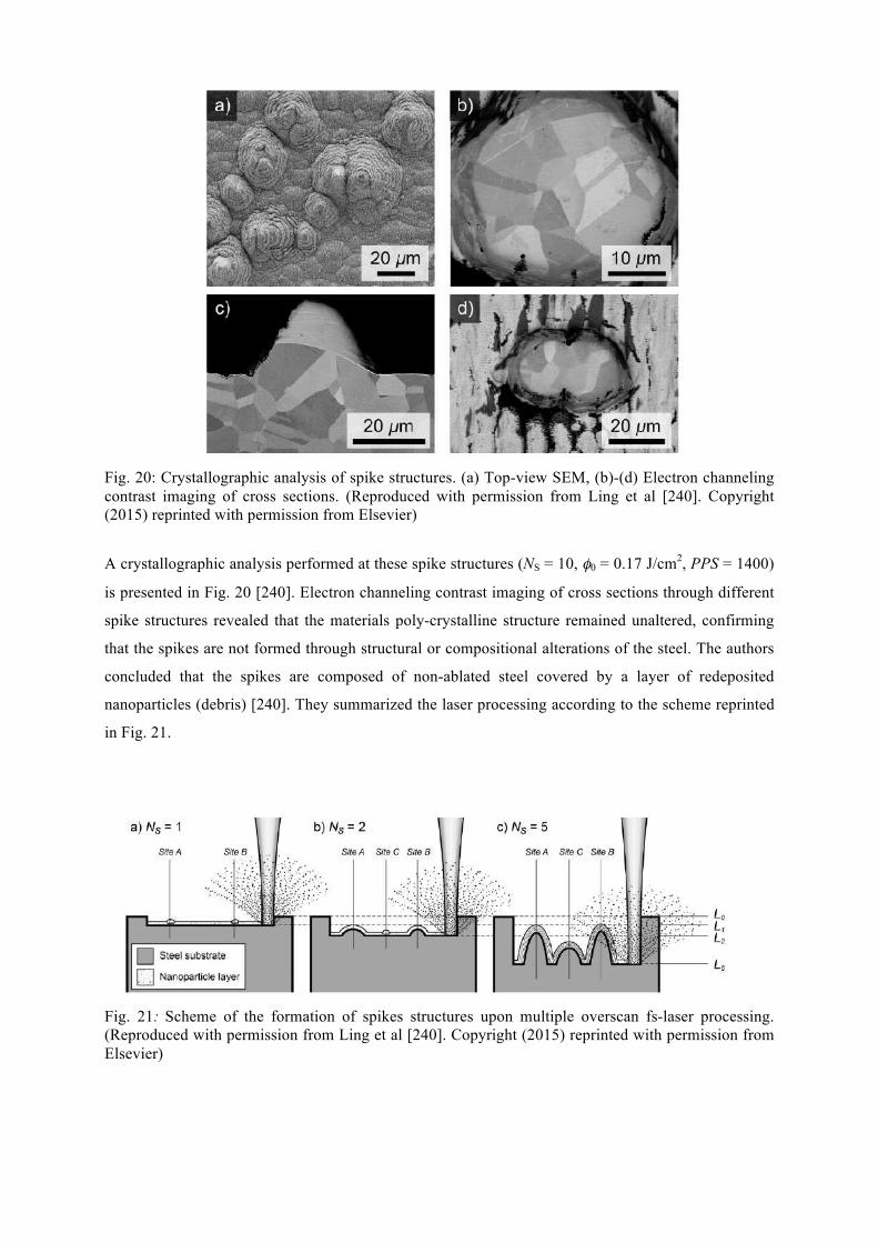
Fig. 20: Crystallographic analysis of spike structures. (a) Top-view SEM, (b)-(d) Electron channeling contrast imaging of cross sections. (Reproduced with permission from Ling et al [240]. Copyright (2015) reprinted with permission from Elsevier)
A crystallographic analysis performed at these spike structures (NS = 10, φ0 = 0.17 J/cm2, PPS = 1400)
is presented in Fig. 20 [240]. Electron channeling contrast imaging of cross sections through different
spike structures revealed that the materials poly-crystalline structure remained unaltered, confirming
that the spikes are not formed through structural or compositional alterations of the steel. The authors
concluded that the spikes are composed of non-ablated steel covered by a layer of redeposited
nanoparticles (debris) [240]. They summarized the laser processing according to the scheme reprinted
in Fig. 21.
Fig. 21: Scheme of the formation of spikes structures upon multiple overscan fs-laser processing. (Reproduced with permission from Ling et al [240]. Copyright (2015) reprinted with permission from Elsevier)
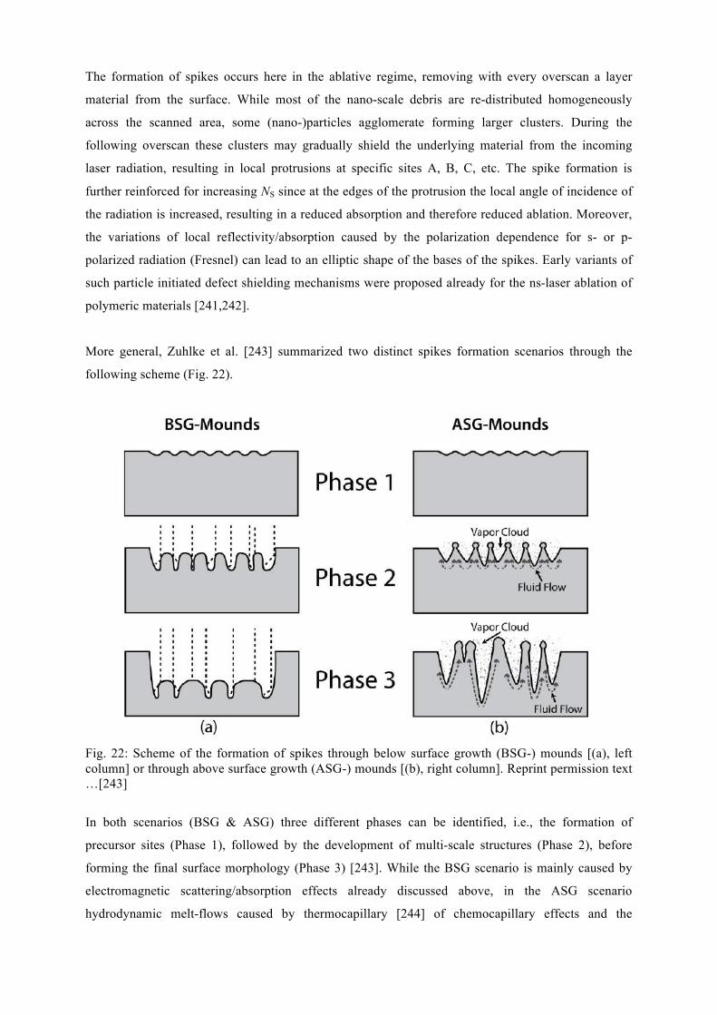
The formation of spikes occurs here in the ablative regime, removing with every overscan a layer
material from the surface. While most of the nano-scale debris are re-distributed homogeneously
across the scanned area, some (nano-)particles agglomerate forming larger clusters. During the
following overscan these clusters may gradually shield the underlying material from the incoming
laser radiation, resulting in local protrusions at specific sites A, B, C, etc. The spike formation is
further reinforced for increasing NS since at the edges of the protrusion the local angle of incidence of
the radiation is increased, resulting in a reduced absorption and therefore reduced ablation. Moreover,
the variations of local reflectivity/absorption caused by the polarization dependence for s- or p-
polarized radiation (Fresnel) can lead to an elliptic shape of the bases of the spikes. Early variants of
such particle initiated defect shielding mechanisms were proposed already for the ns-laser ablation of
polymeric materials [241,242].
More general, Zuhlke et al. [243] summarized two distinct spikes formation scenarios through the
following scheme (Fig. 22).
Fig. 22: Scheme of the formation of spikes through below surface growth (BSG-) mounds [(a), left column] or through above surface growth (ASG-) mounds [(b), right column]. Reprint permission text …[243]
In both scenarios (BSG & ASG) three different phases can be identified, i.e., the formation of
precursor sites (Phase 1), followed by the development of multi-scale structures (Phase 2), before
forming the final surface morphology (Phase 3) [243]. While the BSG scenario is mainly caused by
electromagnetic scattering/absorption effects already discussed above, in the ASG scenario
hydrodynamic melt-flows caused by thermocapillary [244] of chemocapillary effects and the
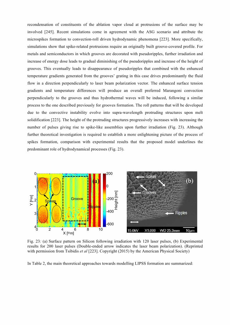
recondensation of constituents of the ablation vapor cloud at protrusions of the surface may be
involved [245]. Recent simulations come in agreement with the ASG scenario and attribute the
microspikes formation to convection-roll driven hydrodynamic phenomena [223]. More specifically,
simulations show that spike-related protrusions require an originally built groove-covered profile. For
metals and semiconductors in which grooves are decorated with pseudoripples, further irradiation and
increase of energy dose leads to gradual diminishing of the pseudoripples and increase of the height of
grooves. This eventually leads to disappearance of pseudoripples that combined with the enhanced
temperature gradients generated from the grooves’ grating in this case drives predominantly the fluid
flow in a direction perpendicularly to laser beam polarization vector. The enhanced surface tension
gradients and temperature differences will produce an overall preferred Marangoni convection
perpendicularly to the grooves and thus hydrothermal waves will be induced, following a similar
process to the one described previously for grooves formation. The roll patterns that will be developed
due to the convective instability evolve into supra-wavelength protruding structures upon melt
solidification [223]. The height of the protruding structures progressively increases with increasing the
number of pulses giving rise to spike-like assemblies upon further irradiation (Fig. 23). Although
further theoretical investigation is required to establish a more enlightening picture of the process of
spikes formation, comparison with experimental results that the proposed model underlines the
predominant role of hydrodynamical processes (Fig. 23).
Fig. 23: (a) Surface pattern on Silicon following irradiation with 120 laser pulses, (b) Experimental results for 200 laser pulses (Double-ended arrow indicates the laser beam polarization). (Reprinted with permission from Tsibidis et al [223]. Copyright (2015) by the American Physical Society)
In Table 2, the main theoretical approaches towards modelling LIPSS formation are summarized:
X [µm]
Y [µ
m]
0 2 4 6 8 10
0
1
2
3
4
Hei
ght [
nm]
-600
-400
-200
0
200
GrooveSpikesRipples
(a) (b) (a) (b)
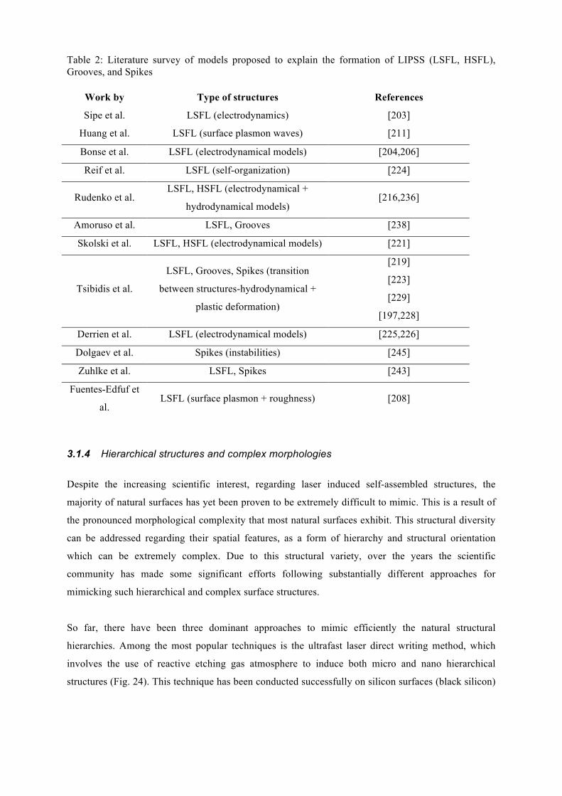
Table 2: Literature survey of models proposed to explain the formation of LIPSS (LSFL, HSFL), Grooves, and Spikes
Work by Type of structures References
Sipe et al. LSFL (electrodynamics) [203]
Huang et al. LSFL (surface plasmon waves) [211]
Bonse et al. LSFL (electrodynamical models) [204,206]
Reif et al. LSFL (self-organization) [224]
Rudenko et al. LSFL, HSFL (electrodynamical +
hydrodynamical models) [216,236]
Amoruso et al. LSFL, Grooves [238]
Skolski et al. LSFL, HSFL (electrodynamical models) [221]
Tsibidis et al.
LSFL, Grooves, Spikes (transition
between structures-hydrodynamical +
plastic deformation)
[219]
[223]
[229]
[197,228]
Derrien et al. LSFL (electrodynamical models) [225,226]
Dolgaev et al. Spikes (instabilities) [245]
Zuhlke et al. LSFL, Spikes [243]
Fuentes-Edfuf et
al. LSFL (surface plasmon + roughness) [208]
3.1.4 Hierarchical structures and complex morphologies
Despite the increasing scientific interest, regarding laser induced self-assembled structures, the
majority of natural surfaces has yet been proven to be extremely difficult to mimic. This is a result of
the pronounced morphological complexity that most natural surfaces exhibit. This structural diversity
can be addressed regarding their spatial features, as a form of hierarchy and structural orientation
which can be extremely complex. Due to this structural variety, over the years the scientific
community has made some significant efforts following substantially different approaches for
mimicking such hierarchical and complex surface structures.
So far, there have been three dominant approaches to mimic efficiently the natural structural
hierarchies. Among the most popular techniques is the ultrafast laser direct writing method, which
involves the use of reactive etching gas atmosphere to induce both micro and nano hierarchical
structures (Fig. 24). This technique has been conducted successfully on silicon surfaces (black silicon)
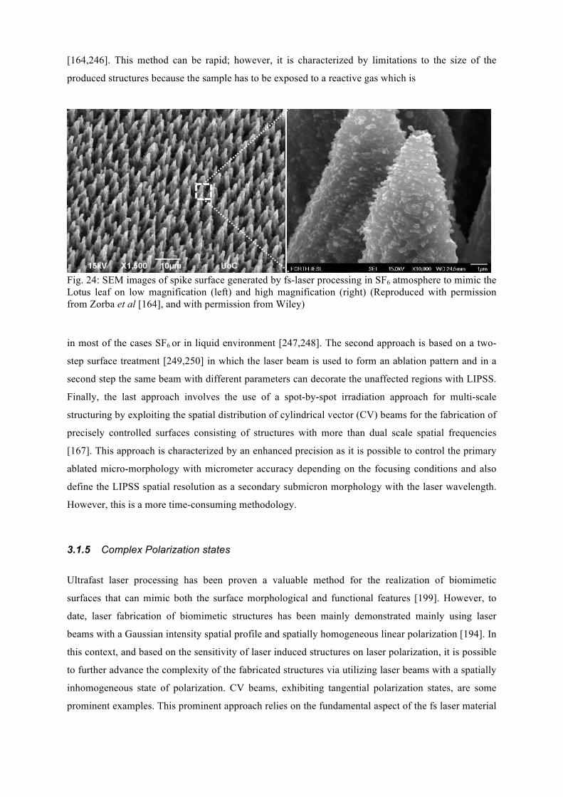
[164,246]. This method can be rapid; however, it is characterized by limitations to the size of the
produced structures because the sample has to be exposed to a reactive gas which is
Fig. 24: SEM images of spike surface generated by fs-laser processing in SF6 atmosphere to mimic the Lotus leaf on low magnification (left) and high magnification (right) (Reproduced with permission from Zorba et al [164], and with permission from Wiley) in most of the cases SF6 or in liquid environment [247,248]. The second approach is based on a two-
step surface treatment [249,250] in which the laser beam is used to form an ablation pattern and in a
second step the same beam with different parameters can decorate the unaffected regions with LIPSS.
Finally, the last approach involves the use of a spot-by-spot irradiation approach for multi-scale
structuring by exploiting the spatial distribution of cylindrical vector (CV) beams for the fabrication of
precisely controlled surfaces consisting of structures with more than dual scale spatial frequencies
[167]. This approach is characterized by an enhanced precision as it is possible to control the primary
ablated micro-morphology with micrometer accuracy depending on the focusing conditions and also
define the LIPSS spatial resolution as a secondary submicron morphology with the laser wavelength.
However, this is a more time-consuming methodology.
3.1.5 Complex Polarization states
Ultrafast laser processing has been proven a valuable method for the realization of biomimetic
surfaces that can mimic both the surface morphological and functional features [199]. However, to
date, laser fabrication of biomimetic structures has been mainly demonstrated mainly using laser
beams with a Gaussian intensity spatial profile and spatially homogeneous linear polarization [194]. In
this context, and based on the sensitivity of laser induced structures on laser polarization, it is possible
to further advance the complexity of the fabricated structures via utilizing laser beams with a spatially
inhomogeneous state of polarization. CV beams, exhibiting tangential polarization states, are some
prominent examples. This prominent approach relies on the fundamental aspect of the fs laser material
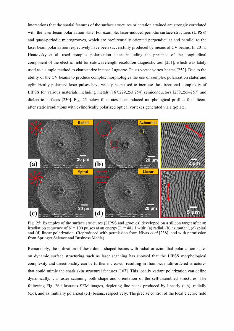
interactions that the spatial features of the surface structures orientation attained are strongly correlated
with the laser beam polarization state. For example, laser-induced periodic surface structures (LIPSS)
and quasi-periodic microgrooves, which are preferentially oriented perpendicular and parallel to the
laser beam polarization respectively have been successfully produced by means of CV beams. In 2011,
Hnatovsky et al. used complex polarization states including the presence of the longitudinal
component of the electric field for sub-wavelength resolution diagnostic tool [251], which was lately
used as a simple method to characterize intense Laguerre-Gauss vector vortex beams [252]. Due to the
ability of the CV beams to produce complex morphologies the use of complex polarization states and
cylindrically polarized laser pulses have widely been used to increase the directional complexity of
LIPSS for various materials including metals [167,229,253,254] semiconductors [238,255–257] and
dielectric surfaces [230]. Fig. 25 below illustrates laser induced morphological profiles for silicon,
after static irradiations with cylindrically polarized optical vortexes generated via a q-plate.
Fig. 25: Examples of the surface structures (LIPSS and grooves) developed on a silicon target after an irradiation sequence of N = 100 pulses at an energy E0 = 48 µJ with: (a) radial, (b) azimuthal, (c) spiral and (d) linear polarization. (Reproduced with permission from Nivas et al [238], and with permission from Springer Science and Business Media) Remarkably, the utilization of these donut-shaped beams with radial or azimuthal polarization states
on dynamic surface structuring such as laser scanning has showed that the LIPSS morphological
complexity and directionality can be further increased, resulting in rhombic, multi-ordered structures
that could mimic the shark skin structural features [167]. This locally variant polarization can define
dynamically, via raster scanning both shape and orientation of the self-assembled structures. The
following Fig. 26 illustrates SEM images, depicting line scans produced by linearly (a,b), radially
(c,d), and azimuthally polarized (e,f) beams, respectively. The precise control of the local electric field
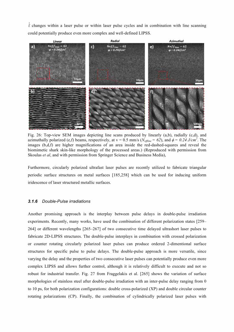
Er changes within a laser pulse or within laser pulse cycles and in combination with line scanning
could potentially produce even more complex and well-defined LIPSS.
Fig. 26: Top-view SEM images depicting line scans produced by linearly (a,b), radially (c,d), and azimuthally polarized (e,f) beams, respectively, at v = 0.5 mm/s (Neffline = 62), and ϕ = 0.24 J/cm2. The images (b,d,f) are higher magnifications of an area inside the red-dashed-squares and reveal the biomimetic shark skin-like morphology of the processed areas.) (Reproduced with permission from Skoulas et al, and with permission from Springer Science and Business Media),
Furthermore, circularly polarized ultrafast laser pulses are recently utilized to fabricate triangular
periodic surface structures on metal surfaces [185,258] which can be used for inducing uniform
iridescence of laser structured metallic surfaces.
3.1.6 Double-Pulse irradiations
Another promising approach is the interplay between pulse delays in double-pulse irradiation
experiments. Recently, many works, have used the combination of different polarization states [259–
264] or different wavelengths [265–267] of two consecutive time delayed ultrashort laser pulses to
fabricate 2D-LIPSS structures. The double-pulse interplays in combination with crossed polarization
or counter rotating circularly polarized laser pulses can produce ordered 2-dimentional surface
structures for specific pulse to pulse delays. The double-pulse approach is more versatile, since
varying the delay and the properties of two consecutive laser pulses can potentially produce even more
complex LIPSS and allows further control, although it is relatively difficult to execute and not so
robust for industrial transfer. Fig. 27 from Fraggelakis et al. [265] shows the variation of surface
morphologies of stainless steel after double-pulse irradiation with an inter-pulse delay ranging from 0
to 10 ps, for both polarization configurations: double cross-polarized (XP) and double circular counter
rotating polarizations (CP). Finally, the combination of cylindrically polarized laser pulses with
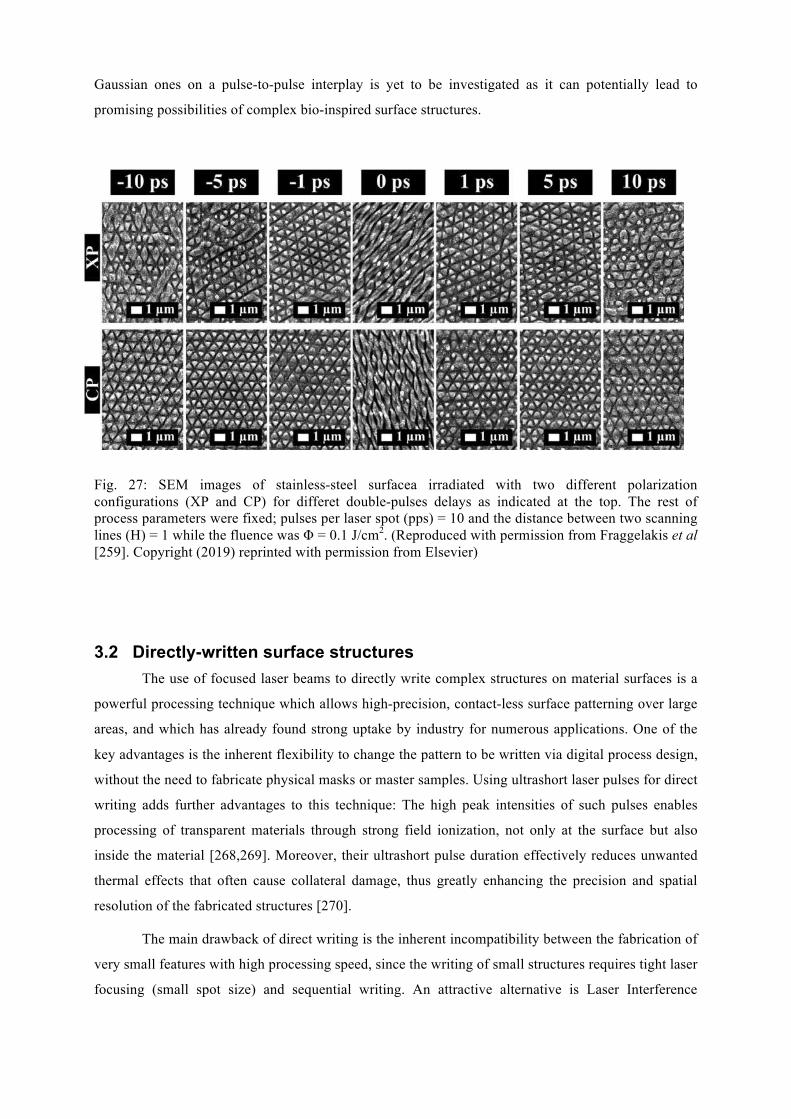
Gaussian ones on a pulse-to-pulse interplay is yet to be investigated as it can potentially lead to
promising possibilities of complex bio-inspired surface structures.
Fig. 27: SEM images of stainless-steel surfacea irradiated with two different polarization configurations (XP and CP) for differet double-pulses delays as indicated at the top. The rest of process parameters were fixed; pulses per laser spot (pps) = 10 and the distance between two scanning lines (H) = 1 while the fluence was Φ = 0.1 J/cm2. (Reproduced with permission from Fraggelakis et al [259]. Copyright (2019) reprinted with permission from Elsevier)
3.2 Directly-written surface structures The use of focused laser beams to directly write complex structures on material surfaces is a
powerful processing technique which allows high-precision, contact-less surface patterning over large
areas, and which has already found strong uptake by industry for numerous applications. One of the
key advantages is the inherent flexibility to change the pattern to be written via digital process design,
without the need to fabricate physical masks or master samples. Using ultrashort laser pulses for direct
writing adds further advantages to this technique: The high peak intensities of such pulses enables
processing of transparent materials through strong field ionization, not only at the surface but also
inside the material [268,269]. Moreover, their ultrashort pulse duration effectively reduces unwanted
thermal effects that often cause collateral damage, thus greatly enhancing the precision and spatial
resolution of the fabricated structures [270].
The main drawback of direct writing is the inherent incompatibility between the fabrication of
very small features with high processing speed, since the writing of small structures requires tight laser
focusing (small spot size) and sequential writing. An attractive alternative is Laser Interference
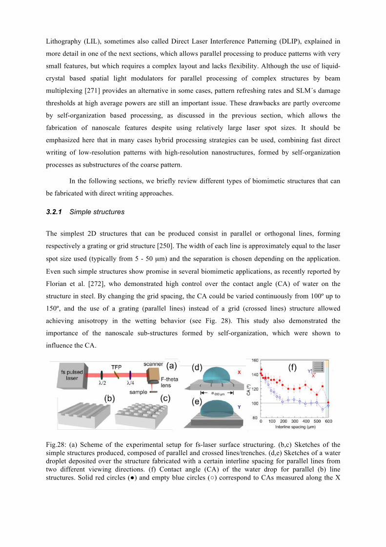
Lithography (LIL), sometimes also called Direct Laser Interference Patterning (DLIP), explained in
more detail in one of the next sections, which allows parallel processing to produce patterns with very
small features, but which requires a complex layout and lacks flexibility. Although the use of liquid-
crystal based spatial light modulators for parallel processing of complex structures by beam
multiplexing [271] provides an alternative in some cases, pattern refreshing rates and SLM´s damage
thresholds at high average powers are still an important issue. These drawbacks are partly overcome
by self-organization based processing, as discussed in the previous section, which allows the
fabrication of nanoscale features despite using relatively large laser spot sizes. It should be
emphasized here that in many cases hybrid processing strategies can be used, combining fast direct
writing of low-resolution patterns with high-resolution nanostructures, formed by self-organization
processes as substructures of the coarse pattern.
In the following sections, we briefly review different types of biomimetic structures that can
be fabricated with direct writing approaches.
3.2.1 Simple structures
The simplest 2D structures that can be produced consist in parallel or orthogonal lines, forming
respectively a grating or grid structure [250]. The width of each line is approximately equal to the laser
spot size used (typically from 5 - 50 µm) and the separation is chosen depending on the application.
Even such simple structures show promise in several biomimetic applications, as recently reported by
Florian et al. [272], who demonstrated high control over the contact angle (CA) of water on the
structure in steel. By changing the grid spacing, the CA could be varied continuously from 100º up to
150º, and the use of a grating (parallel lines) instead of a grid (crossed lines) structure allowed
achieving anisotropy in the wetting behavior (see Fig. 28). This study also demonstrated the
importance of the nanoscale sub-structures formed by self-organization, which were shown to
influence the CA.
Fig.28: (a) Scheme of the experimental setup for fs-laser surface structuring. (b,c) Sketches of the simple structures produced, composed of parallel and crossed lines/trenches. (d,e) Sketches of a water droplet deposited over the structure fabricated with a certain interline spacing for parallel lines from two different viewing directions. (f) Contact angle (CA) of the water drop for parallel (b) line structures. Solid red circles (●) and empty blue circles (○) correspond to CAs measured along the X
and Y viewing positions, respectively. Adapted with permission from Ref. [272], Copyright (2018) American Chemical Society.
3.2.2 Complex patterns
The complexity of directly-written structures is only limited by the spatial resolution achievable. The
most common implementation is the use of a laser scanning head, composed of two galvanometric
mirrors combined with a telecentric lens to focus the beam. The desired structure is designed with
computer software and the trajectories are sent to the laser scanner, which scans the beam over the
static sample. Linear processing speeds in the m/s range are easily accessible in the case of planar
samples [212]. For non-planar samples, an additional module is added that allows changing the focal
position along the beam propagation direction. A well-known example for a highly complex 3D object
fabricated that way is a metal stent inserted in a patient’s blood vessel to prevent closure [273]. A
recent example of a biomimetic structure fabricated by direct writing is a fluidic diode for passive
unidirectional liquid transport, inspired by the topography of the spermathecal duct of fleas [59].
3.2.3 Processing in vacuum/gas atmosphere
An important factor that strongly influences both the morphology and the chemical composition of the
laser-processed surface is the presence or absence of air or other types of gas during processing [242].
A gas environment of a given pressure enables chemical reactions (for instance oxidation in Ge [274])
at the surface of the laser-heated material, whereas working in vacuum increases the expansion
velocity of the ablating material [275], strongly reducing debris formation around the laser processed
region. Using non-oxygen based reactive gases allows the formation of chemically different surfaces
with radically different properties [242,276]. It has to be said, though, that the complexity and thus
cost of laser processing strongly increases when not working in air.
3.2.4 Interference patterning
As mentioned in the beginning of this section, the drawback of direct writing is the processing speed
due to the need of writing each structure sequentially. Laser interference lithography (LIL) allows
overcoming this limitation and writing a whole array of structures in parallel. In this sense, LIL is
similar to self-organization based approaches, but does not rely on a material response to generate an
interfering surface wave. Instead, the surface is irradiated by two or more coherent laser pulses [277]
that interfere, generating a periodic intensity pattern that can be imprinted upon single pulse exposure
into the material to form periodic structures over centimeter areas. For the case of two beams, the
period Λ is a direct function of the laser wavelength λ and the half-angle θ formed between the beams,
according to Λ = λ /(2⋅sin(θ)). If three or more beams interfere, complex intensity patterns can be
produced, whose shapes are also a function of the relative intensities of the individual beams and the
projected directions of incidence, defined by the angles α, β, γ (see Fig. 29(a)).
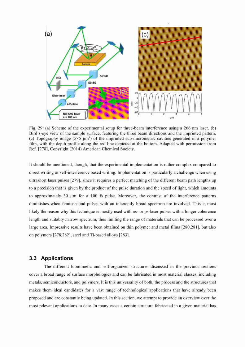
Fig. 29: (a) Scheme of the experimental setup for three-beam interference using a 266 nm laser. (b) Bird’s-eye view of the sample surface, featuring the three beam directions and the imprinted pattern. (c) Topography image (5×5 µm2) of the imprinted sub-micrometric cavities generated in a polymer film, with the depth profile along the red line depicted at the bottom. Adapted with permission from Ref. [278], Copyright (2014) American Chemical Society.
It should be mentioned, though, that the experimental implementation is rather complex compared to
direct writing or self-interference based writing. Implementation is particularly a challenge when using
ultrashort laser pulses [279], since it requires a perfect matching of the different beam path lengths up
to a precision that is given by the product of the pulse duration and the speed of light, which amounts
to approximately 30 µm for a 100 fs pulse. Moreover, the contrast of the interference patterns
diminishes when femtosecond pulses with an inherently broad spectrum are involved. This is most
likely the reason why this technique is mostly used with ns- or ps-laser pulses with a longer coherence
length and suitably narrow spectrum, thus limiting the range of materials that can be processed over a
large area. Impressive results have been obtained on thin polymer and metal films [280,281], but also
on polymers [278,282], steel and Ti-based alloys [283].
3.3 Applications The different biomimetic and self-organized structures discussed in the previous sections
cover a broad range of surface morphologies and can be fabricated in most material classes, including
metals, semiconductors, and polymers. It is this universality of both, the process and the structures that
makes them ideal candidates for a vast range of technological applications that have already been
proposed and are constantly being updated. In this section, we attempt to provide an overview over the
most relevant applications to date. In many cases a certain structure fabricated in a given material has
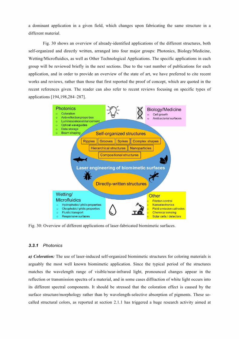
a dominant application in a given field, which changes upon fabricating the same structure in a
different material.
Fig. 30 shows an overview of already-identified applications of the different structures, both
self-organized and directly written, arranged into four major groups: Photonics, Biology/Medicine,
Wetting/Microfluidics, as well as Other Technological Applications. The specific applications in each
group will be reviewed briefly in the next sections. Due to the vast number of publications for each
application, and in order to provide an overview of the state of art, we have preferred to cite recent
works and reviews, rather than those that first reported the proof of concept, which are quoted in the
recent references given. The reader can also refer to recent reviews focusing on specific types of
applications [194,198,284–287].
Fig. 30: Overview of different applications of laser-fabricated biomimetic surfaces.
3.3.1 Photonics a) Coloration: The use of laser-induced self-organized biomimetic structures for coloring materials is
arguably the most well known biomimetic application. Since the typical period of the structures
matches the wavelength range of visible/near-infrared light, pronounced changes appear in the
reflection or transmission spectra of a material, and in some cases diffraction of white light occurs into
its different spectral components. It should be stressed that the coloration effect is caused by the
surface structure/morphology rather than by wavelength-selective absorption of pigments. These so-
called structural colors, as reported at section 2.1.1 has triggered a huge research activity aimed at
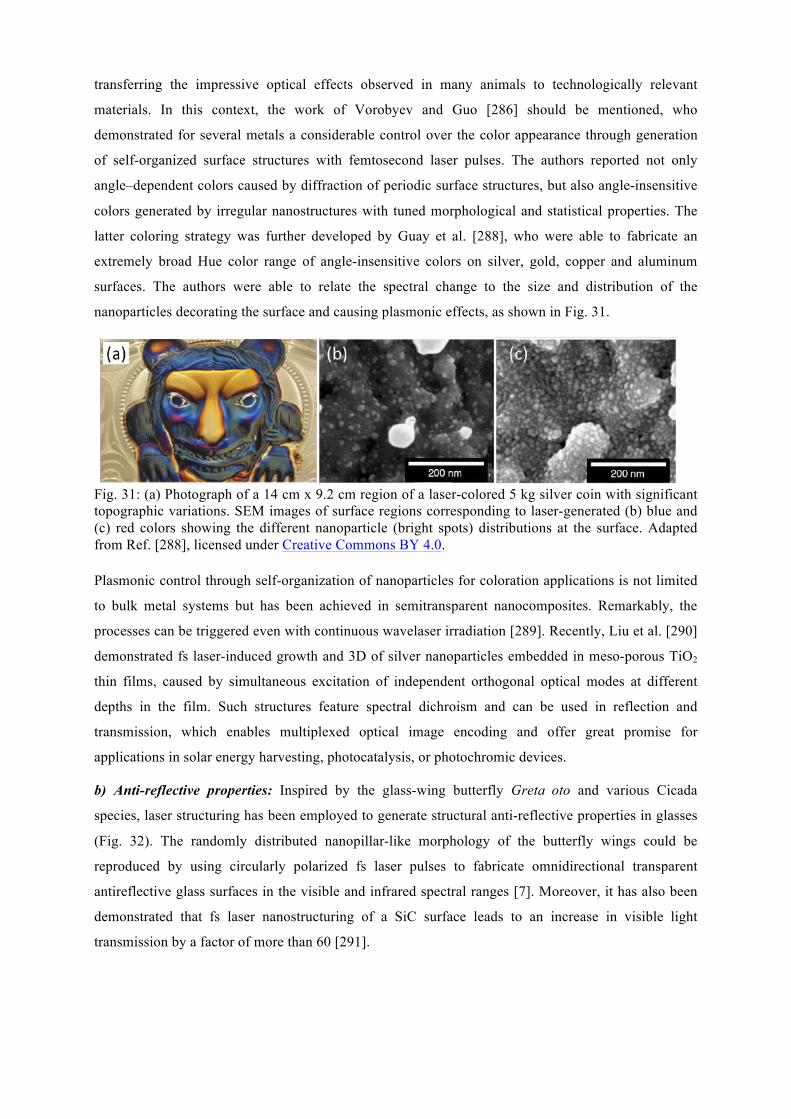
transferring the impressive optical effects observed in many animals to technologically relevant
materials. In this context, the work of Vorobyev and Guo [286] should be mentioned, who
demonstrated for several metals a considerable control over the color appearance through generation
of self-organized surface structures with femtosecond laser pulses. The authors reported not only
angle–dependent colors caused by diffraction of periodic surface structures, but also angle-insensitive
colors generated by irregular nanostructures with tuned morphological and statistical properties. The
latter coloring strategy was further developed by Guay et al. [288], who were able to fabricate an
extremely broad Hue color range of angle-insensitive colors on silver, gold, copper and aluminum
surfaces. The authors were able to relate the spectral change to the size and distribution of the
nanoparticles decorating the surface and causing plasmonic effects, as shown in Fig. 31.
Fig. 31: (a) Photograph of a 14 cm x 9.2 cm region of a laser-colored 5 kg silver coin with significant topographic variations. SEM images of surface regions corresponding to laser-generated (b) blue and (c) red colors showing the different nanoparticle (bright spots) distributions at the surface. Adapted from Ref. [288], licensed under Creative Commons BY 4.0. Plasmonic control through self-organization of nanoparticles for coloration applications is not limited
to bulk metal systems but has been achieved in semitransparent nanocomposites. Remarkably, the
processes can be triggered even with continuous wavelaser irradiation [289]. Recently, Liu et al. [290]
demonstrated fs laser-induced growth and 3D of silver nanoparticles embedded in meso-porous TiO2
thin films, caused by simultaneous excitation of independent orthogonal optical modes at different
depths in the film. Such structures feature spectral dichroism and can be used in reflection and
transmission, which enables multiplexed optical image encoding and offer great promise for
applications in solar energy harvesting, photocatalysis, or photochromic devices.
b) Anti-reflective properties: Inspired by the glass-wing butterfly Greta oto and various Cicada
species, laser structuring has been employed to generate structural anti-reflective properties in glasses
(Fig. 32). The randomly distributed nanopillar-like morphology of the butterfly wings could be
reproduced by using circularly polarized fs laser pulses to fabricate omnidirectional transparent
antireflective glass surfaces in the visible and infrared spectral ranges [7]. Moreover, it has also been
demonstrated that fs laser nanostructuring of a SiC surface leads to an increase in visible light
transmission by a factor of more than 60 [291].
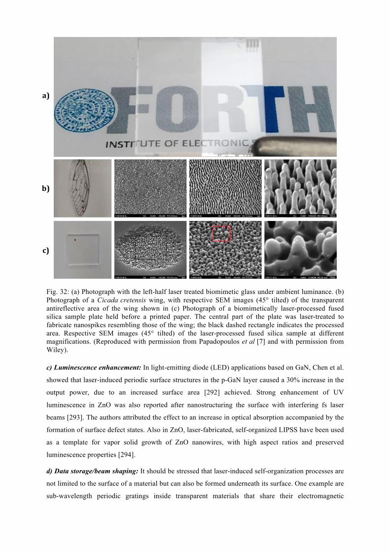
Fig. 32: (a) Photograph with the left-half laser treated biomimetic glass under ambient luminance. (b) Photograph of a Cicada cretensis wing, with respective SEM images (45° tilted) of the transparent antireflective area of the wing shown in (c) Photograph of a biomimetically laser-processed fused silica sample plate held before a printed paper. The central part of the plate was laser-treated to fabricate nanospikes resembling those of the wing; the black dashed rectangle indicates the processed area. Respective SEM images (45° tilted) of the laser-processed fused silica sample at different magnifications. (Reproduced with permission from Papadopoulos et al [7] and with permission from Wiley). c) Luminescence enhancement: In light-emitting diode (LED) applications based on GaN, Chen et al.
showed that laser-induced periodic surface structures in the p-GaN layer caused a 30% increase in the
output power, due to an increased surface area [292] achieved. Strong enhancement of UV
luminescence in ZnO was also reported after nanostructuring the surface with interfering fs laser
beams [293]. The authors attributed the effect to an increase in optical absorption accompanied by the
formation of surface defect states. Also in ZnO, laser-fabricated, self-organized LIPSS have been used
as a template for vapor solid growth of ZnO nanowires, with high aspect ratios and preserved
luminescence properties [294].
d) Data storage/beam shaping: It should be stressed that laser-induced self-organization processes are
not limited to the surface of a material but can also be formed underneath its surface. One example are
sub-wavelength periodic gratings inside transparent materials that share their electromagnetic
a)
b)
c)
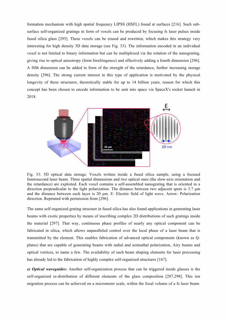
formation mechanism with high spatial frequency LIPSS (HSFL) found at surfaces [216]. Such sub-
surface self-organized gratings in form of voxels can be produced by focusing fs laser pulses inside
fused silica glass [295]. These voxels can be erased and rewritten, which makes this strategy very
interesting for high density 3D data storage (see Fig. 33). The information encoded in an individual
voxel is not limited to binary information but can be multiplexed via the rotation of the nanograting,
giving rise to optical anisotropy (form birefringence) and effectively adding a fourth dimension [296].
A fifth dimension can be added in form of the strength of the retardance, further increasing storage
density [296]. The strong current interest in this type of application is motivated by the physical
longevity of these structures, theoretically stable for up to 14 billion years, reason for which this
concept has been chosen to encode information to be sent into space via SpaceX's rocket launch in
2018.
Fig. 33: 5D optical data storage. Voxels written inside a fused silica sample, using a focused femtosecond laser beam. Three spatial dimensions and two optical ones (the slow-axis orientation and the retardance) are exploited. Each voxel contains a self-assembled nanograting that is oriented in a direction perpendicular to the light polarization. The distance between two adjacent spots is 3.7 µm and the distance between each layer is 20 µm. E: Electric field of light wave. Arrow: Polarization direction. Reprinted with permission from [296]. The same self-organized grating structure in fused silica has also found applications in generating laser
beams with exotic properties by means of inscribing complex 2D distributions of such gratings inside
the material [297]. That way, continuous phase profiles of nearly any optical component can be
fabricated in silica, which allows unparalleled control over the local phase of a laser beam that is
transmitted by the element. This enables fabrication of advanced optical components (known as Q-
plates) that are capable of generating beams with radial and azimuthal polarization, Airy beams and
optical vortices, to name a few. The availability of such beam shaping elements for laser processing
has already led to the fabrication of highly complex self-organized structures [167].
e) Optical waveguides: Another self-organization process that can be triggered inside glasses is the
self-organized re-distribution of different elements of the glass composition [287,298]. This ion
migration process can be achieved on a micrometer scale, within the focal volume of a fs laser beam.
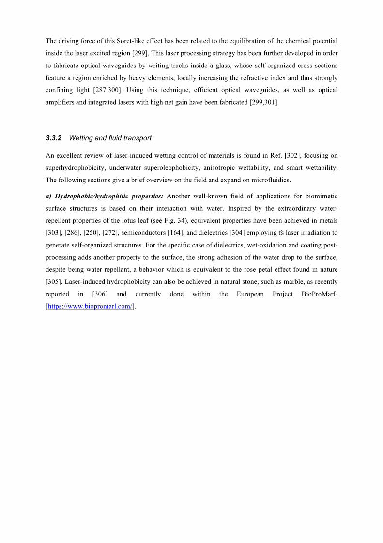
The driving force of this Soret-like effect has been related to the equilibration of the chemical potential
inside the laser excited region [299]. This laser processing strategy has been further developed in order
to fabricate optical waveguides by writing tracks inside a glass, whose self-organized cross sections
feature a region enriched by heavy elements, locally increasing the refractive index and thus strongly
confining light [287,300]. Using this technique, efficient optical waveguides, as well as optical
amplifiers and integrated lasers with high net gain have been fabricated [299,301].
3.3.2 Wetting and fluid transport An excellent review of laser-induced wetting control of materials is found in Ref. [302], focusing on
superhydrophobicity, underwater superoleophobicity, anisotropic wettability, and smart wettability.
The following sections give a brief overview on the field and expand on microfluidics.
a) Hydrophobic/hydrophilic properties: Another well-known field of applications for biomimetic
surface structures is based on their interaction with water. Inspired by the extraordinary water-
repellent properties of the lotus leaf (see Fig. 34), equivalent properties have been achieved in metals
[303], [286], [250], [272], semiconductors [164], and dielectrics [304] employing fs laser irradiation to
generate self-organized structures. For the specific case of dielectrics, wet-oxidation and coating post-
processing adds another property to the surface, the strong adhesion of the water drop to the surface,
despite being water repellant, a behavior which is equivalent to the rose petal effect found in nature
[305]. Laser-induced hydrophobicity can also be achieved in natural stone, such as marble, as recently
reported in [306] and currently done within the European Project BioProMarL
[https://www.biopromarl.com/].
Fig. 34: (a) Top row: pictures of a water droplet on an artificial structured silicon surface (dark area). Bottom row: SEM images of the artificial surface (scale bars, left: 5 µm, right: 1 µm). (b) Top: pictures of water droplets on a Nelumbo nucifera Lotus leaf. Bottom: SEM images of the leaf surface (scale bars, left: 5 µm, right: 1 µm). (c) Water droplets placed on laser-processed, wet-oxidized and coated structures on fused silica. The high adhesion is demonstrated by the hanging drop in the embedded image (d). (e) Photograph of the lizard Phrynosoma platyrhinos, which has a hydrophilic skin that enables fast and directional water transport. (f-g) Sequence of images recorded with a time lap of 0.2 seconds, featuring directional capillary transport of a liquid in surface channels on steel, fabricated by laser and resembling the lizard skin. (a,b) Reproduced with permission from [164] Copyright 2008. Wiley-VCH Verlag. GmbH & Co. KGaA. (c,d) Reprinted with permission from Ref. [305], (e-g) Reprinted with permission from Ref. [64]. Other plants and animals feature specific hydrophilic or hydrophobic properties, including the bark
bug, Texas horned lizard as well as the Namib Desert beetle. These properties have also been
successfully conferred to metals [64,166,171,307], glass [305] and silicon [302,308] using laser
processing.
b) Oleophobic/oleophilic properties: In metals, the very same self-organized structures that feature
hydrophobic behavior present oleophilic properties [171,309]. Such properties can be efficiently
exploited in technical applications using oil-based lubricants, since they contribute to the fast and
homogenous distribution of the lubricant, especially under conditions of starved lubrication [310].
The processing of “morphological gradients” featuring a continuous transition between LIPSS and
hierarchical spikes in a processed surface region may even result in an mainly unidirectional oil
transport from the rippled to spikes regions [171]. Underwater superoleophobicity, inspired by fish-
scales that protect the fish from contamination in oil-polluted water, has been achieved in glass and
silicon via fs laser processing [302].
c) Fluidic transport: The Texas horned lizard is a role model for unidirectional water transport, since
the channel network on its skin causes water to flow preferentially towards the snout, even against
gravity. Transferring this bionic concept via direct laser writing to polymers and metals was recently
demonstrated [311], [64] (see Fig. 34). Furthermore, a remarkable water transport velocity has been
demonstrated on fs laser-fabricated silicon structures exhibiting a surface tension gradient [312].
Another straightforward method to fabricate complex 3D microfluidic channels in a transparent
material is by focusing an ultrashort laser beam inside fused silica, writing the desired trajectories. As
explained in the previous section on data storage, self-organized planar nanogratings can be formed in
the focal volume. The structural change accompanied by the grating formation leads to a strong
preferential chemical etching in certain acids of these structures compared to the unexposed material.
The use of this technique has enabled laser-fabrication of optofluidic lab-on-chips, combining
microfluidic with photonic devices [313].
d) Control of condensation rates and impact on anti-icing properties: The fabrication of surfaces
with superhydrophobic and ice-repellent properties constitutes nowadays a challenging task. These
properties have an increased significance due to the abundance of potential applications where anti-
icing properties, especially for aeronautic applications[314], given that the formation of supercooled
water droplets can significantly reduce the aerodynamic performance and the operational capability.
Most of the reported studies state that there is a clear relation between the spatial period and the
surface microstructure depth, in the ice adhesion strength under low temperature conditions. Anti-icing
surface properties are directly correlated with the wetting properties, i.e superhydrophobicity. So far
there are prominent examples of surfaces that does not favor the ice accretion or extend the water
freezing time for metal surfaces directly processed with laser pulses[179,315,316], as well as with
combined laser texturing and chemical surface tailoring[317]. Furthermore, there are also studies of
the ice-phobicity effect induced in Polytetrafluoroethylene (PTFE) with rapid and cost efficient with
CW laser [318] and silicone rubber[319] achieved with picosecond laser sources. Were there was a
correlation on the mechanical stability of the laser textured rubber with the forming ice freezing
kinetics. It has been shown that droplet condensation occurs in the early stage of frosting before ice
crystals appear; Experimental reports indicated that the presence of hierarchical microstructures on the
patterned surface increased the available nucleation sites, resulting in a larger number of condensate
site formation and leading to a superhydrophobic state [320,321]. The hydrophobic nature of the
microstructured surface influence also the droplet geometrical shape, reduce droplet growth and delay
droplet solidification which are an additional reason behind the ice-prevention [322].
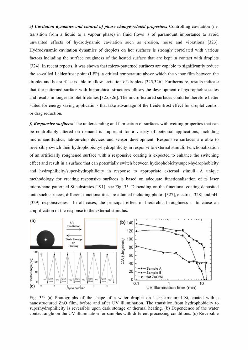
e) Cavitation dynamics and control of phase change-related properties: Controlling cavitation (i.e.
transition from a liquid to a vapour phase) in fluid flows is of paramount importance to avoid
unwanted effects of hydrodynamic cavitation such as erosion, noise and vibrations [323].
Hydrodynamic cavitation dynamics of droplets on hot surfaces is strongly correlated with various
factors including the surface roughness of the heated surface that are kept in contact with droplets
[324]. In recent reports, it was shown that micro-patterned surfaces are capable to significantly reduce
the so-called Leidenfrost point (LFP), a critical temperature above which the vapor film between the
droplet and hot surface is able to allow levitation of droplets [325,326]. Furthermore, results indicate
that the patterned surface with hierarchical structures allows the development of hydrophobic states
and results in longer droplet lifetimes [325,326]. The micro-textured surfaces could be therefore better
suited for energy saving applications that take advantage of the Leidenfrost effect for droplet control
or drag reduction.
f) Responsive surfaces: The understanding and fabrication of surfaces with wetting properties that can
be controllably altered on demand is important for a variety of potential applications, including
micro/nanofluidics, lab-on-chip devices and sensor development. Responsive surfaces are able to
reversibly switch their hydrophobicity/hydrophilicity in response to external stimuli. Functionalization
of an artificially roughened surface with a responsive coating is expected to enhance the switching
effect and result in a surface that can potentially switch between hydrophobicity/super-hydrophobicity
and hydrophilicity/super-hydrophilicity in response to appropriate external stimuli. A unique
methodology for creating responsive surfaces is based on adequate functionalization of fs laser
micro/nano patterned Si substrates [191], see Fig. 35. Depending on the functional coating deposited
onto such surfaces, different functionalities are attained including photo- [327], electro- [328] and pH-
[329] responsiveness. In all cases, the principal effect of hierarchical roughness is to cause an
amplification of the response to the external stimulus.
Fig. 35: (a) Photographs of the shape of a water droplet on laser-structured Si, coated with a nanostructured ZnO film, before and after UV illumination. The transition from hydrophobicity to superhydrophilicity is reversible upon dark storage or thermal heating. (b) Dependence of the water contact angle on the UV illumination for samples with different processing conditions. (c) Reversible
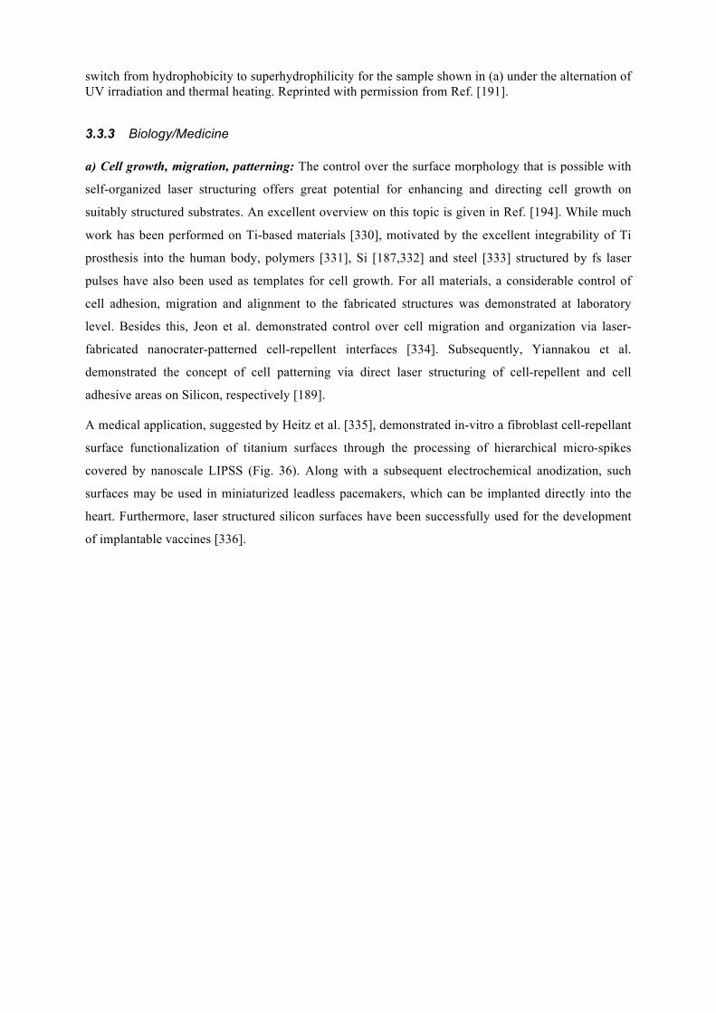
switch from hydrophobicity to superhydrophilicity for the sample shown in (a) under the alternation of UV irradiation and thermal heating. Reprinted with permission from Ref. [191].
3.3.3 Biology/Medicine a) Cell growth, migration, patterning: The control over the surface morphology that is possible with
self-organized laser structuring offers great potential for enhancing and directing cell growth on
suitably structured substrates. An excellent overview on this topic is given in Ref. [194]. While much
work has been performed on Ti-based materials [330], motivated by the excellent integrability of Ti
prosthesis into the human body, polymers [331], Si [187,332] and steel [333] structured by fs laser
pulses have also been used as templates for cell growth. For all materials, a considerable control of
cell adhesion, migration and alignment to the fabricated structures was demonstrated at laboratory
level. Besides this, Jeon et al. demonstrated control over cell migration and organization via laser-
fabricated nanocrater-patterned cell-repellent interfaces [334]. Subsequently, Yiannakou et al.
demonstrated the concept of cell patterning via direct laser structuring of cell-repellent and cell
adhesive areas on Silicon, respectively [189].
A medical application, suggested by Heitz et al. [335], demonstrated in-vitro a fibroblast cell-repellant
surface functionalization of titanium surfaces through the processing of hierarchical micro-spikes
covered by nanoscale LIPSS (Fig. 36). Along with a subsequent electrochemical anodization, such
surfaces may be used in miniaturized leadless pacemakers, which can be implanted directly into the
heart. Furthermore, laser structured silicon surfaces have been successfully used for the development
of implantable vaccines [336].
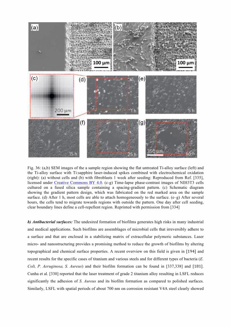
Fig. 36: (a,b) SEM images of the a sample region showing the flat untreated Ti-alloy surface (left) and the Ti-alloy surface with Ti:sapphire laser-induced spikes combined with electrochemical oxidation (right): (a) without cells and (b) with fibroblasts 1 week after seeding: Reproduced from Ref. [335], licensed under Creative Commons BY 4.0. (c-g) Time-lapse phase-contrast images of NIH3T3 cells cultured on a fused silica sample containing a spacing-gradient pattern. (c) Schematic diagram showing the gradient pattern design, which was fabricated on the red marked area on the sample surface. (d) After 1 h, most cells are able to attach homogeneously to the surface. (e–g) After several hours, the cells tend to migrate towards regions with outside the pattern. One day after cell seeding, clear boundary lines define a cell-repellent region. Reprinted with permission from [334]
b) Antibacterial surfaces: The undesired formation of biofilms generates high risks in many industrial
and medical applications. Such biofilms are assemblages of microbial cells that irreversibly adhere to
a surface and that are enclosed in a stabilizing matrix of extracellular polymeric substances. Laser
micro- and nanostructuring provides a promising method to reduce the growth of biofilms by altering
topographical and chemical surface properties. A recent overview on this field is given in [194] and
recent results for the specific cases of titanium and various steels and for different types of bacteria (E.
Coli, P. Aeruginosa, S. Aureus) and their biofilm formation can be found in [337,338] and [181].
Cunha et al. [330] reported that the laser treatment of grade 2 titanium alloy resulting in LSFL reduces
significantly the adhesion of S. Aureus and its biofilm formation as compared to polished surfaces.
Similarly, LSFL with spatial periods of about 700 nm on corrosion resistant V4A steel clearly showed
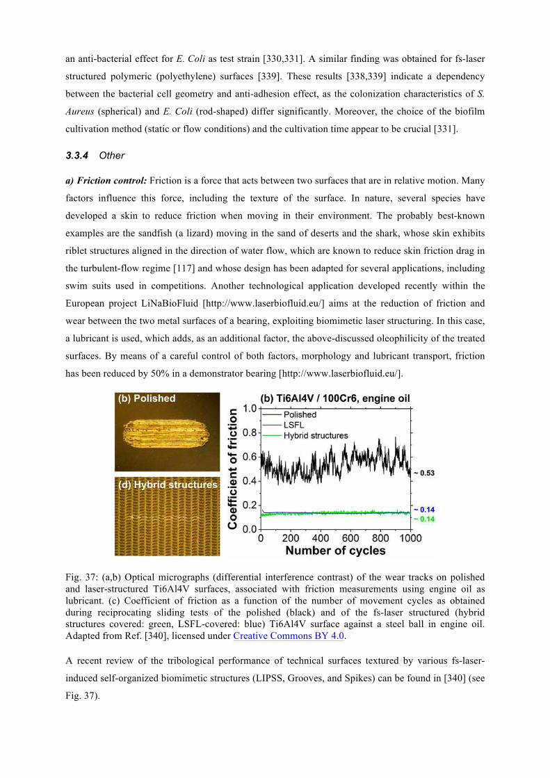
an anti-bacterial effect for E. Coli as test strain [330,331]. A similar finding was obtained for fs-laser
structured polymeric (polyethylene) surfaces [339]. These results [338,339] indicate a dependency
between the bacterial cell geometry and anti-adhesion effect, as the colonization characteristics of S.
Aureus (spherical) and E. Coli (rod-shaped) differ significantly. Moreover, the choice of the biofilm
cultivation method (static or flow conditions) and the cultivation time appear to be crucial [331].
3.3.4 Other a) Friction control: Friction is a force that acts between two surfaces that are in relative motion. Many
factors influence this force, including the texture of the surface. In nature, several species have
developed a skin to reduce friction when moving in their environment. The probably best-known
examples are the sandfish (a lizard) moving in the sand of deserts and the shark, whose skin exhibits
riblet structures aligned in the direction of water flow, which are known to reduce skin friction drag in
the turbulent-flow regime [117] and whose design has been adapted for several applications, including
swim suits used in competitions. Another technological application developed recently within the
European project LiNaBioFluid [http://www.laserbiofluid.eu/] aims at the reduction of friction and
wear between the two metal surfaces of a bearing, exploiting biomimetic laser structuring. In this case,
a lubricant is used, which adds, as an additional factor, the above-discussed oleophilicity of the treated
surfaces. By means of a careful control of both factors, morphology and lubricant transport, friction
has been reduced by 50% in a demonstrator bearing [http://www.laserbiofluid.eu/].
Fig. 37: (a,b) Optical micrographs (differential interference contrast) of the wear tracks on polished and laser-structured Ti6Al4V surfaces, associated with friction measurements using engine oil as lubricant. (c) Coefficient of friction as a function of the number of movement cycles as obtained during reciprocating sliding tests of the polished (black) and of the fs-laser structured (hybrid structures covered: green, LSFL-covered: blue) Ti6Al4V surface against a steel ball in engine oil. Adapted from Ref. [340], licensed under Creative Commons BY 4.0. A recent review of the tribological performance of technical surfaces textured by various fs-laser-
induced self-organized biomimetic structures (LIPSS, Grooves, and Spikes) can be found in [340] (see
Fig. 37).
b) Nanoelectronics: Fabricating self-organized structures with feature sizes less than 1 micrometer is
also interesting for the field of nanoelectronics. Among the materials of interest for this application is,
for instance silicon, which is the very pillar the industry is built on. The use of laser structuring for
writing circuits offers not only a more flexible and mask-less method compared to lithographic
approaches, it also allows switching the phase from crystalline to amorphous and back by using laser
pulses of different durations. Recently, high-quality, self-organized amorphous fringe structures have
been written in crystalline silicon, whose period can be tuned and which can be erased via laser
irradiation [213]. Since the electrical properties of both phases are very different, the structures can be
used to introduce anisotropy in the electrical conductivity. Finally, the fabrication of high regular,
erasable and rewritable periodic surface patterns on silver metaphosphate glass by means of ultrashort
pulsed laser processing, has been reported [341] which could potentially lead to ultrafast laser data
storage on soft glass surfaces.
c) Field emission cathodes: Field-electron emission refers to the quantum mechanical tunneling of
electrons from a solid cathode (generally in the shape of a sharp tip) into vacuum under the influence
of a strong electric field. Laser structured dense arrays of high-aspect ratio micro/nano spikes with
controllability of density and roughness ratio has been demonstrated to serve as superior electron
emitters for cold [342,343] as well as thermionic field emission applications [344].
d) Sensing: The pronounced hierarchy of many types of self-organized structures in metals leads to
strong electromagnetic field enhancement upon illumination by light. This effect is responsible for
surface enhanced Raman scattering (SERS), which can be exploited for increasing the sensitivity in
detection of certain chemicals. Microfluidic SERS chips have already been fabricated by all-
femtosecond-laser processing [345].
e) Solar cells / detectors: Some of the early applications of laser-induced self-organized structures are
based on the efficient absorption light throughout the visible and near infrared range by spike
structures in silicon processed in the presence of a gas containing sulfur hexafluoride and other
dopants. Termed “black silicon”, the group of E. Mazur has pioneered applications of these structures
as sensitive layers in photodiodes, photodetectors, solar cells, field emission and other photoelectric
devices [276].
4 Laser fabrication of biomimetic surfaces on soft materials and related applications
Table 3: Biomimetic examples showing the capabilities for laser manufacturing of soft material surfaces.
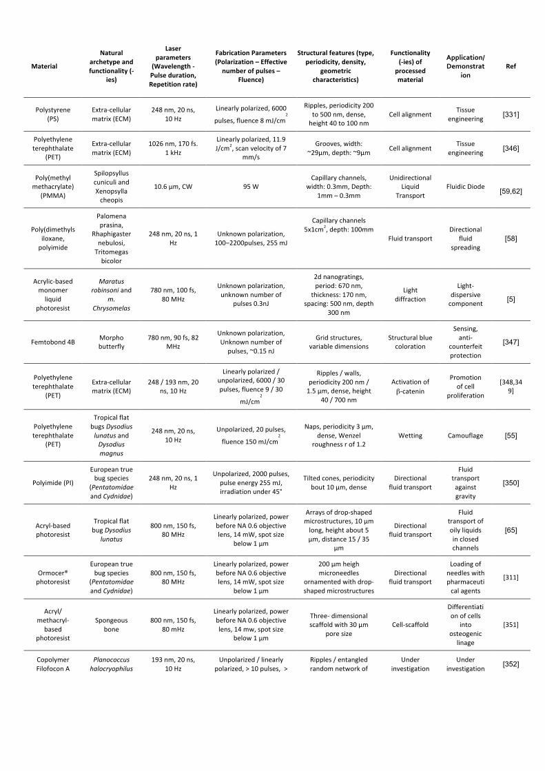
Material
Naturalarchetypeandfunctionality(-
ies)
Laserparameters
(Wavelength-Pulseduration,Repetitionrate)
FabricationParameters(Polarization–Effectivenumberofpulses–
Fluence)
Structuralfeatures(type,periodicity,density,
geometriccharacteristics)
Functionality (-ies)of
processedmaterial
Application/Demonstrat
ion Ref
Polystyrene(PS)
Extra-cellularmatrix(ECM)
248nm,20ns,10Hz
Linearlypolarized,6000
pulses,fluence8mJ/cm2
Ripples,periodicity200to500nm,dense,height40to100nm
CellalignmentTissue
engineering [331]
Polyethyleneterephthalate
(PET)
Extra-cellularmatrix(ECM)
1026nm,170fs.1kHz
Linearlypolarized,11.9J/cm2,scanvelocityof7
mm/s
Grooves,width:~29μm,depth:~9μm Cellalignment Tissue
engineering [346]
Poly(methylmethacrylate)
(PMMA)
SpilopsylluscuniculiandXenopsyllacheopis
10.6μm,CW 95WCapillarychannels,
width:0.3mm,Depth:1mm–0.3mm
UnidirectionalLiquid
TransportFluidicDiode
[59,62]
Poly(dimethylsiloxane,polyimide
Palomenaprasina,
Rhaphigasternebulosi,Tritomegasbicolor
248nm,20ns,1Hz
Unknownpolarization,100–2200pulses,255mJ
Capillarychannels5x1cm2,depth:100mm
FluidtransportDirectional
fluidspreading
[58]
Acrylic-basedmonomerliquid
photoresist
Maratusrobinsoniand
m.Chrysomelas
780nm,100fs,80MHz
Unknownpolarization,unknownnumberof
pulses0.3nJ
2dnanogratings,period:670nm,
thickness:170nm,spacing:500nm,depth
300nm
Lightdiffraction
Light-dispersivecomponent [5]
Femtobond4B Morphobutterfly
780nm,90fs,82MHz
Unknownpolarization,Unknownnumberof
pulses,~0.15nJ
Gridstructures,variabledimensions
Structuralbluecoloration
Sensing,anti-
counterfeitprotection
[347]
Polyethyleneterephthalate
(PET)
Extra-cellularmatrix(ECM)
248/193nm,20ns,10Hz
Linearlypolarized/unpolarized,6000/30pulses,fluence9/30
mJ/cm2
Ripples/walls,periodicity200nm/1.5µm,dense,height
40/700nm
Activationofβ-catenin
Promotionofcell
proliferation
[348,349]
Polyethyleneterephthalate
(PET)
TropicalflatbugsDysodiuslunatusandDysodiusmagnus
248nm,20ns,10Hz
Unpolarized,20pulses,
fluence150mJ/cm2
Naps,periodicity3µm,dense,Wenzel
roughnessrof1.2 Wetting Camouflage [55]
Polyimide(PI)
Europeantruebugspecies
(PentatomidaeandCydnidae)
248nm,20ns,1Hz
Unpolarized,2000pulses,pulseenergy255mJ,irradiationunder45°
Tiltedcones,periodicitybout10µm,dense
Directionalfluidtransport
Fluidtransportagainstgravity
[350]
Acryl-basedphotoresist
TropicalflatbugDysodius
lunatus
800nm,150fs,80MHz
Linearlypolarized,powerbeforeNA0.6objectivelens,14mW,spotsize
below1µm
Arraysofdrop-shapedmicrostructures,10µmlong,heightabout5µm,distance15/35
µm
Directionalfluidtransport
Fluidtransportofoilyliquidsinclosedchannels
[65]
Ormocer®photoresist
Europeantruebugspecies
(PentatomidaeandCydnidae)
800nm,150fs,80MHz
Linearlypolarized,powerbeforeNA0.6objectivelens,14mW,spotsize
below1µm
200µmheighmicroneedles
ornamentedwithdrop-shapedmicrostructures
Directionalfluidtransport
Loadingofneedleswithpharmaceuticalagents
[311]
Acryl/methacryl-based
photoresist
Spongeousbone
800nm,150fs,80mHz
Linearlypolarized,powerbeforeNA0.6objectivelens,14mw,spotsize
below1µm
Three-dimensionalscaffoldwith30µm
poresize Cell-scaffold
Differentiationofcells
intoosteogeniclinage
[351]
CopolymerFilofoconA
Planococcushalocryophilus
193nm,20ns,10Hz
Unpolarized/linearlypolarized,>10pulses,>
Ripples/entangledrandomnetworkof
Underinvestigation
Underinvestigation [352]
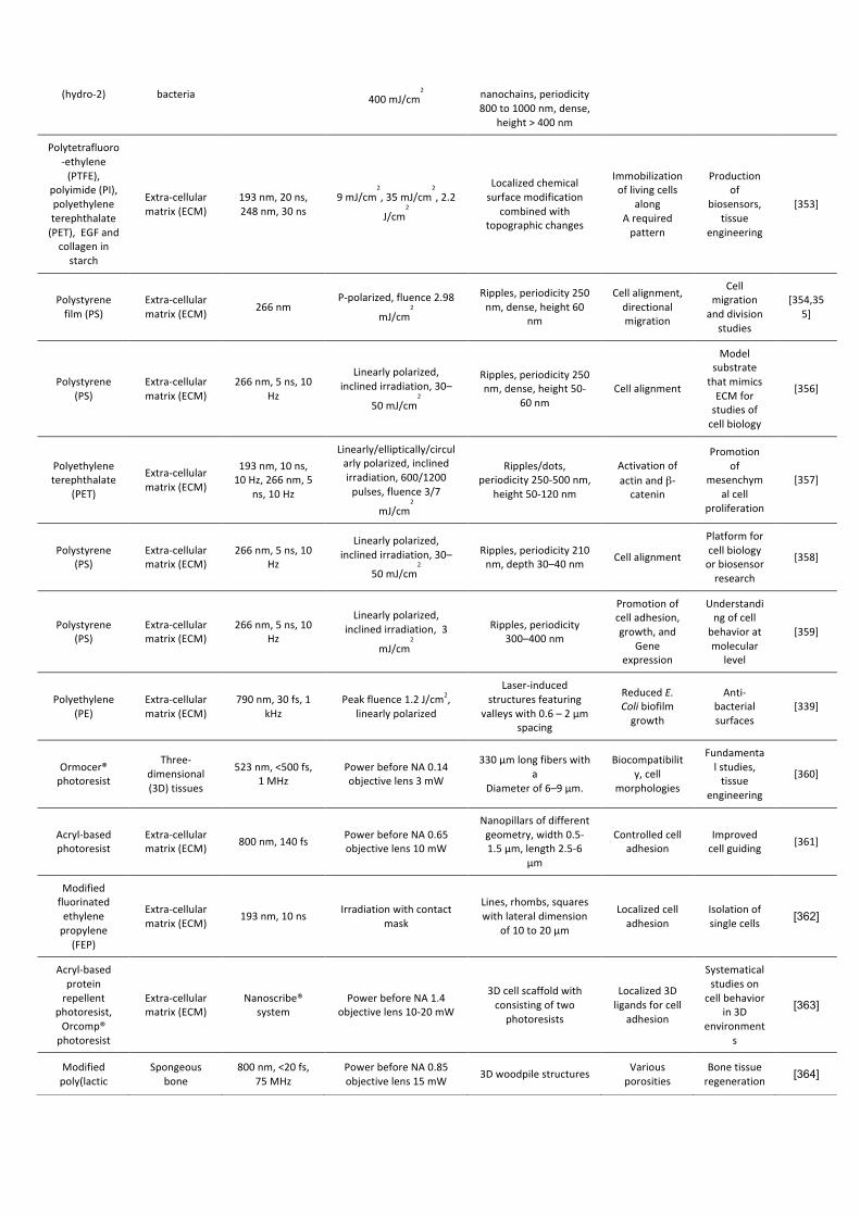
(hydro-2) bacteria 400mJ/cm2 nanochains,periodicity
800to1000nm,dense,height>400nm
Polytetrafluoro-ethylene(PTFE),
polyimide(PI),polyethyleneterephthalate(PET),EGFandcollageninstarch
Extra-cellularmatrix(ECM)
193nm,20ns,248nm,30ns
9mJ/cm2,35mJ/cm
2,2.2
J/cm2
Localizedchemicalsurfacemodification
combinedwithtopographicchanges
Immobilizationoflivingcells
along Arequiredpattern
Productionof
biosensors,tissue
engineering
[353]
Polystyrenefilm(PS)
Extra-cellularmatrix(ECM) 266nm
P-polarized,fluence2.98
mJ/cm2
Ripples,periodicity250nm,dense,height60
nm
Cellalignment,directionalmigration
Cellmigrationanddivisionstudies
[354,355]
Polystyrene(PS)
Extra-cellularmatrix(ECM)
266nm,5ns,10Hz
Linearlypolarized,inclinedirradiation,30–
50mJ/cm2
Ripples,periodicity250nm,dense,height50-
60nm Cellalignment
ModelsubstratethatmimicsECMforstudiesofcellbiology
[356]
Polyethyleneterephthalate
(PET)
Extra-cellularmatrix(ECM)
193nm,10ns,10Hz,266nm,5
ns,10Hz
Linearly/elliptically/circularlypolarized,inclinedirradiation,600/1200pulses,fluence3/7
mJ/cm2
Ripples/dots,periodicity250-500nm,
height50-120nm
Activationofactinandβ-catenin
Promotionof
mesenchymalcell
proliferation
[357]
Polystyrene(PS)
Extra-cellularmatrix(ECM)
266nm,5ns,10Hz
Linearlypolarized,inclinedirradiation,30–
50mJ/cm2
Ripples,periodicity210nm,depth30–40nm Cellalignment
Platformforcellbiologyorbiosensorresearch
[358]
Polystyrene(PS)
Extra-cellularmatrix(ECM)
266nm,5ns,10Hz
Linearlypolarized,inclinedirradiation,3
mJ/cm2
Ripples,periodicity300–400nm
Promotionofcelladhesion,growth,and
Geneexpression
Understandingofcellbehavioratmolecular
level
[359]
Polyethylene(PE)
Extra-cellularmatrix(ECM)
790nm,30fs,1kHz
Peakfluence1.2J/cm2,linearlypolarized
Laser-inducedstructuresfeaturing
valleyswith0.6–2µmspacing
ReducedE.Colibiofilmgrowth
Anti-bacterialsurfaces
[339]
Ormocer®photoresist
Three-dimensional (3D)tissues
523nm,<500fs, 1MHz
PowerbeforeNA0.14objectivelens3mW
330μmlongfiberswitha
Diameterof6–9μm.
Biocompatibility,cell
morphologies
Fundamentalstudies,tissue
engineering
[360]
Acryl-basedphotoresist
Extra-cellularmatrix(ECM) 800nm,140fs PowerbeforeNA0.65
objectivelens10mW
Nanopillarsofdifferentgeometry,width0.5-1.5µm,length2.5-6
µm
Controlledcelladhesion
Improvedcellguiding [361]
Modifiedfluorinatedethylenepropylene
(FEP)
Extra-cellularmatrix(ECM) 193nm,10ns Irradiationwithcontact
mask
Lines,rhombs,squareswithlateraldimension
of10to20µm
Localizedcelladhesion
Isolationofsinglecells [362]
Acryl-basedproteinrepellent
photoresist,Orcomp®photoresist
Extra-cellularmatrix(ECM)
Nanoscribe®system
PowerbeforeNA1.4objectivelens10-20mW
3Dcellscaffoldwithconsistingoftwophotoresists
Localized3Dligandsforcell
adhesion
Systematicalstudieson
cellbehaviorin3D
environments
[363]
Modifiedpoly(lactic
Spongeousbone
800nm,<20fs,75MHz
PowerbeforeNA0.85objectivelens15mW 3Dwoodpilestructures Various
porosities Bonetissueregeneration [364]
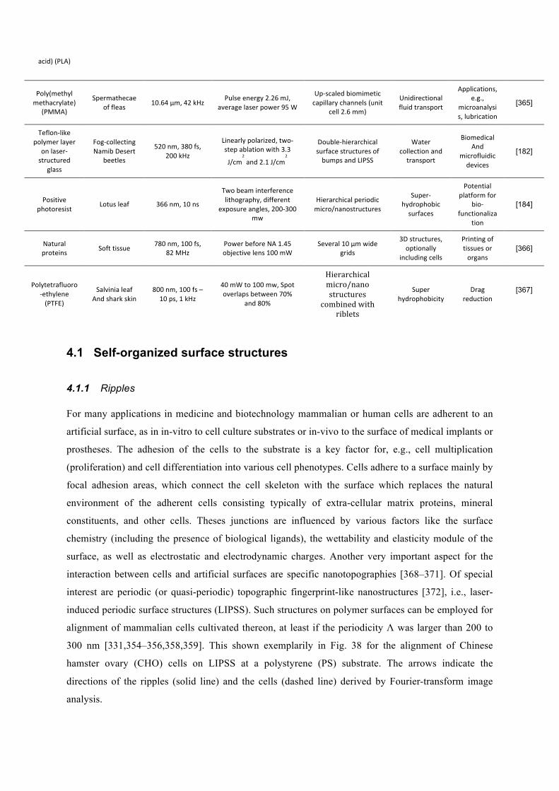
4.1 Self-organized surface structures
4.1.1 Ripples For many applications in medicine and biotechnology mammalian or human cells are adherent to an
artificial surface, as in in-vitro to cell culture substrates or in-vivo to the surface of medical implants or
prostheses. The adhesion of the cells to the substrate is a key factor for, e.g., cell multiplication
(proliferation) and cell differentiation into various cell phenotypes. Cells adhere to a surface mainly by
focal adhesion areas, which connect the cell skeleton with the surface which replaces the natural
environment of the adherent cells consisting typically of extra-cellular matrix proteins, mineral
constituents, and other cells. Theses junctions are influenced by various factors like the surface
chemistry (including the presence of biological ligands), the wettability and elasticity module of the
surface, as well as electrostatic and electrodynamic charges. Another very important aspect for the
interaction between cells and artificial surfaces are specific nanotopographies [368–371]. Of special
interest are periodic (or quasi-periodic) topographic fingerprint-like nanostructures [372], i.e., laser-
induced periodic surface structures (LIPSS). Such structures on polymer surfaces can be employed for
alignment of mammalian cells cultivated thereon, at least if the periodicity Λ was larger than 200 to
300 nm [331,354–356,358,359]. This shown exemplarily in Fig. 38 for the alignment of Chinese
hamster ovary (CHO) cells on LIPSS at a polystyrene (PS) substrate. The arrows indicate the
directions of the ripples (solid line) and the cells (dashed line) derived by Fourier-transform image
analysis.
acid)(PLA)
Poly(methylmethacrylate)
(PMMA)
Spermathecaeoffleas 10.64µm,42kHz Pulseenergy2.26mJ,
averagelaserpower95W
Up-scaledbiomimeticcapillarychannels(unit
cell2.6mm)
Unidirectionalfluidtransport
Applications,e.g.,
microanalysis,lubrication
[365]
Teflon-likepolymerlayer
onlaser-structured
glass
Fog-collectingNamibDesert
beetles
520nm,380fs,200kHz
Linearlypolarized,two-stepablationwith3.3
J/cm2and2.1J/cm
2
Double-hierarchicalsurfacestructuresofbumpsandLIPSS
Watercollectionandtransport
Biomedical And
microfluidicdevices
[182]
Positivephotoresist Lotusleaf 366nm,10ns
Twobeaminterferencelithography,different
exposureangles,200-300mw
Hierarchicalperiodicmicro/nanostructures
Super-hydrophobicsurfaces
Potentialplatformfor
bio-functionaliza
tion
[184]
Naturalproteins Softtissue 780nm,100fs,
82MHz PowerbeforeNA1.45objectivelens100mW
Several10µmwidegrids
3Dstructures,optionally
includingcells
Printingoftissuesororgans
[366]
Polytetrafluoro-ethylene(PTFE)
SalvinialeafAndsharkskin
800nm,100fs–10ps,1kHz
40mWto100mw,Spotoverlapsbetween70%
and80%
Hierarchicalmicro/nanostructures
combinedwithriblets
Superhydrophobicity
Dragreduction
[367]
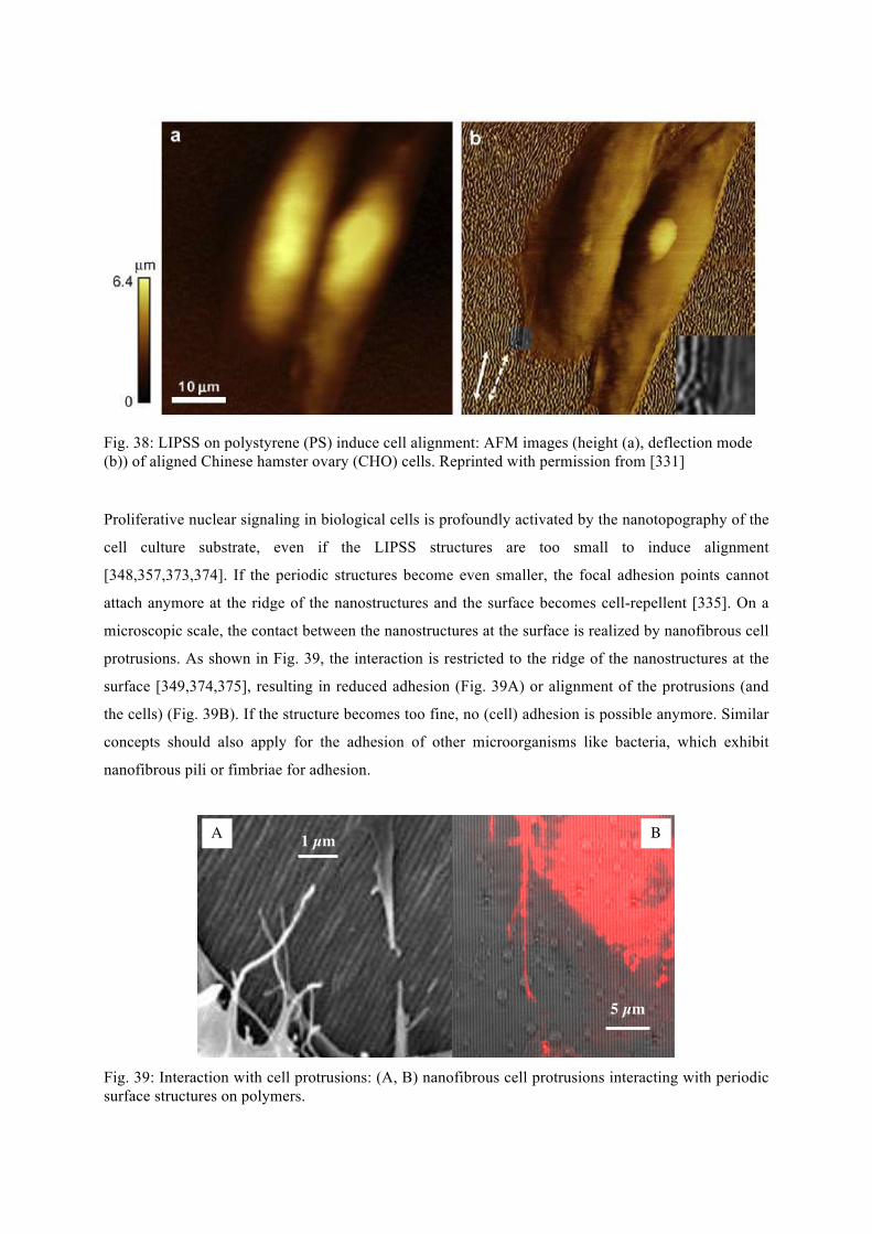
Fig. 38: LIPSS on polystyrene (PS) induce cell alignment: AFM images (height (a), deflection mode (b)) of aligned Chinese hamster ovary (CHO) cells. Reprinted with permission from [331] Proliferative nuclear signaling in biological cells is profoundly activated by the nanotopography of the
cell culture substrate, even if the LIPSS structures are too small to induce alignment
[348,357,373,374]. If the periodic structures become even smaller, the focal adhesion points cannot
attach anymore at the ridge of the nanostructures and the surface becomes cell-repellent [335]. On a
microscopic scale, the contact between the nanostructures at the surface is realized by nanofibrous cell
protrusions. As shown in Fig. 39, the interaction is restricted to the ridge of the nanostructures at the
surface [349,374,375], resulting in reduced adhesion (Fig. 39A) or alignment of the protrusions (and
the cells) (Fig. 39B). If the structure becomes too fine, no (cell) adhesion is possible anymore. Similar
concepts should also apply for the adhesion of other microorganisms like bacteria, which exhibit
nanofibrous pili or fimbriae for adhesion.
Fig. 39: Interaction with cell protrusions: (A, B) nanofibrous cell protrusions interacting with periodic surface structures on polymers.
A 1 µm
5 µm
B
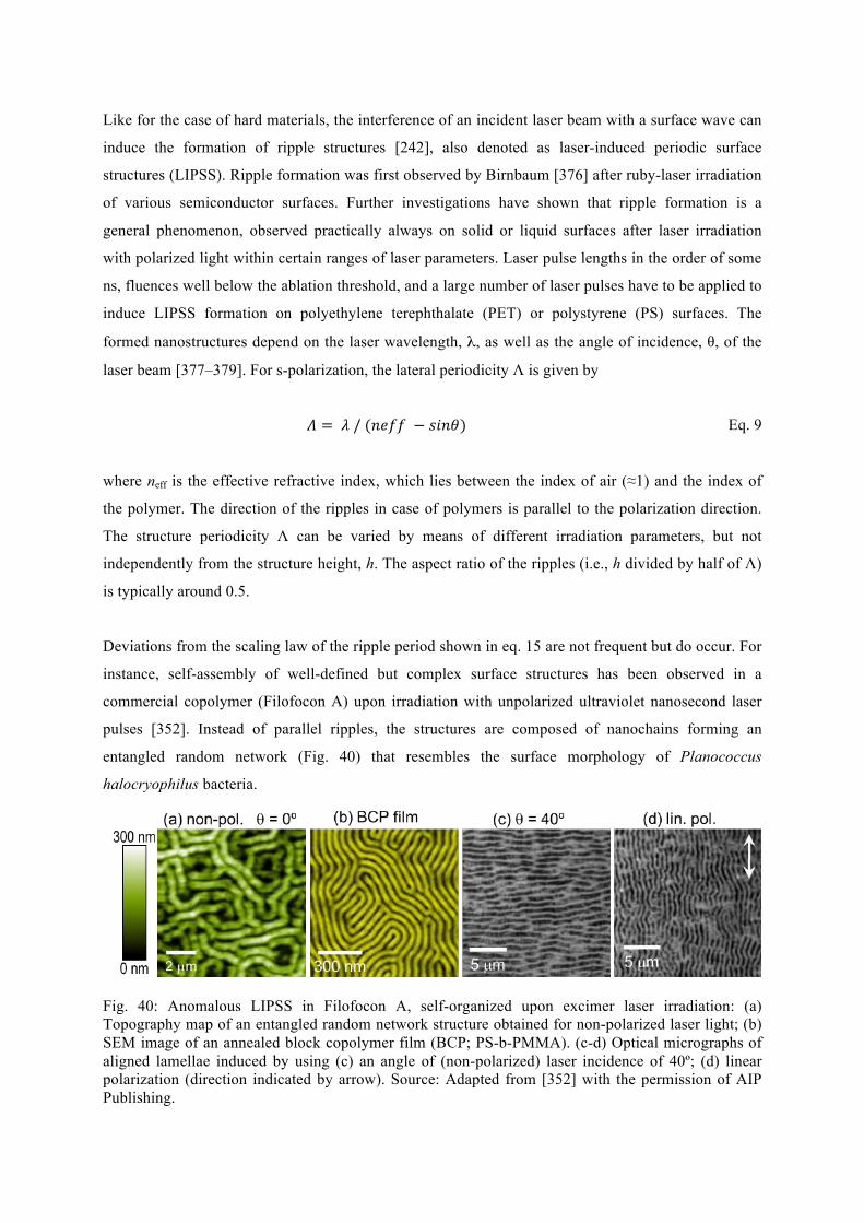
Like for the case of hard materials, the interference of an incident laser beam with a surface wave can
induce the formation of ripple structures [242], also denoted as laser-induced periodic surface
structures (LIPSS). Ripple formation was first observed by Birnbaum [376] after ruby-laser irradiation
of various semiconductor surfaces. Further investigations have shown that ripple formation is a
general phenomenon, observed practically always on solid or liquid surfaces after laser irradiation
with polarized light within certain ranges of laser parameters. Laser pulse lengths in the order of some
ns, fluences well below the ablation threshold, and a large number of laser pulses have to be applied to
induce LIPSS formation on polyethylene terephthalate (PET) or polystyrene (PS) surfaces. The
formed nanostructures depend on the laser wavelength, λ, as well as the angle of incidence, θ, of the
laser beam [377–379]. For s-polarization, the lateral periodicity Λ is given by
𝛬 = 𝜆 / (𝑛𝑒𝑓𝑓 − 𝑠𝑖𝑛𝜃) Eq. 9
where neff is the effective refractive index, which lies between the index of air (≈1) and the index of
the polymer. The direction of the ripples in case of polymers is parallel to the polarization direction.
The structure periodicity Λ can be varied by means of different irradiation parameters, but not
independently from the structure height, h. The aspect ratio of the ripples (i.e., h divided by half of Λ)
is typically around 0.5.
Deviations from the scaling law of the ripple period shown in eq. 15 are not frequent but do occur. For
instance, self-assembly of well-defined but complex surface structures has been observed in a
commercial copolymer (Filofocon A) upon irradiation with unpolarized ultraviolet nanosecond laser
pulses [352]. Instead of parallel ripples, the structures are composed of nanochains forming an
entangled random network (Fig. 40) that resembles the surface morphology of Planococcus
halocryophilus bacteria.
Fig. 40: Anomalous LIPSS in Filofocon A, self-organized upon excimer laser irradiation: (a) Topography map of an entangled random network structure obtained for non-polarized laser light; (b) SEM image of an annealed block copolymer film (BCP; PS-b-PMMA). (c-d) Optical micrographs of aligned lamellae induced by using (c) an angle of (non-polarized) laser incidence of 40º; (d) linear polarization (direction indicated by arrow). Source: Adapted from [352] with the permission of AIP Publishing.
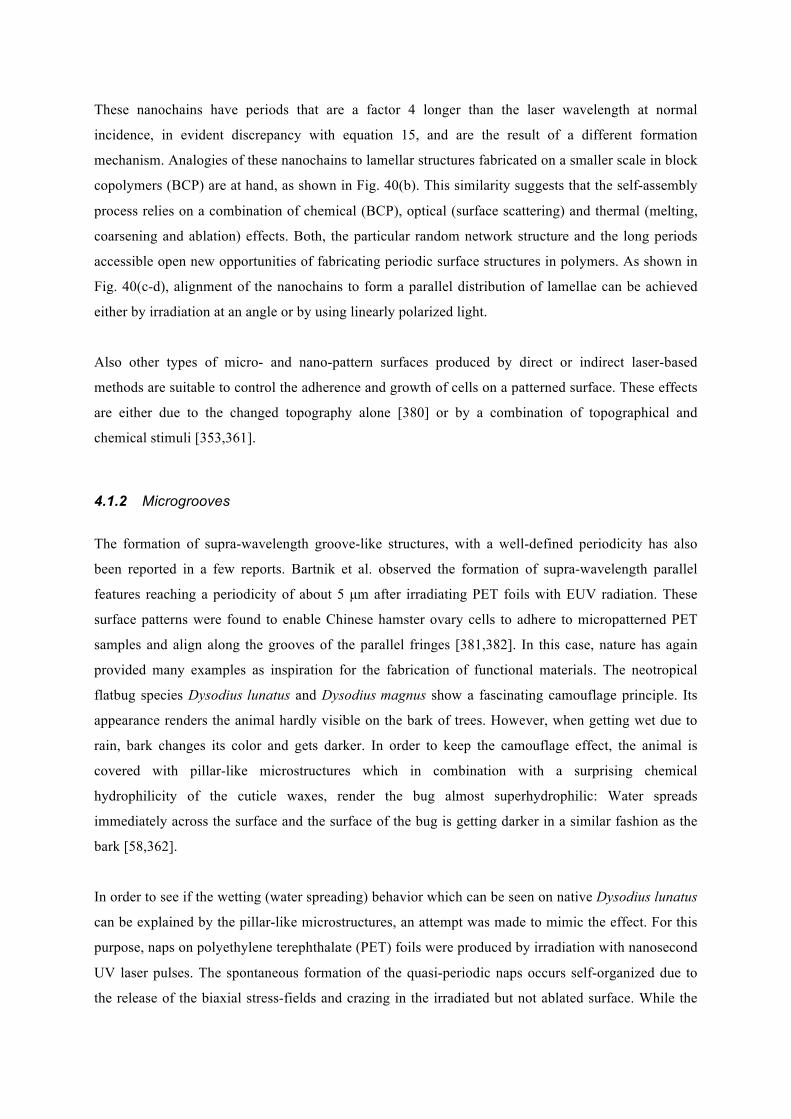
These nanochains have periods that are a factor 4 longer than the laser wavelength at normal
incidence, in evident discrepancy with equation 15, and are the result of a different formation
mechanism. Analogies of these nanochains to lamellar structures fabricated on a smaller scale in block
copolymers (BCP) are at hand, as shown in Fig. 40(b). This similarity suggests that the self-assembly
process relies on a combination of chemical (BCP), optical (surface scattering) and thermal (melting,
coarsening and ablation) effects. Both, the particular random network structure and the long periods
accessible open new opportunities of fabricating periodic surface structures in polymers. As shown in
Fig. 40(c-d), alignment of the nanochains to form a parallel distribution of lamellae can be achieved
either by irradiation at an angle or by using linearly polarized light.
Also other types of micro- and nano-pattern surfaces produced by direct or indirect laser-based
methods are suitable to control the adherence and growth of cells on a patterned surface. These effects
are either due to the changed topography alone [380] or by a combination of topographical and
chemical stimuli [353,361].
4.1.2 Microgrooves
The formation of supra-wavelength groove-like structures, with a well-defined periodicity has also
been reported in a few reports. Bartnik et al. observed the formation of supra-wavelength parallel
features reaching a periodicity of about 5 µm after irradiating PET foils with EUV radiation. These
surface patterns were found to enable Chinese hamster ovary cells to adhere to micropatterned PET
samples and align along the grooves of the parallel fringes [381,382]. In this case, nature has again
provided many examples as inspiration for the fabrication of functional materials. The neotropical
flatbug species Dysodius lunatus and Dysodius magnus show a fascinating camouflage principle. Its
appearance renders the animal hardly visible on the bark of trees. However, when getting wet due to
rain, bark changes its color and gets darker. In order to keep the camouflage effect, the animal is
covered with pillar-like microstructures which in combination with a surprising chemical
hydrophilicity of the cuticle waxes, render the bug almost superhydrophilic: Water spreads
immediately across the surface and the surface of the bug is getting darker in a similar fashion as the
bark [58,362].
In order to see if the wetting (water spreading) behavior which can be seen on native Dysodius lunatus
can be explained by the pillar-like microstructures, an attempt was made to mimic the effect. For this
purpose, naps on polyethylene terephthalate (PET) foils were produced by irradiation with nanosecond
UV laser pulses. The spontaneous formation of the quasi-periodic naps occurs self-organized due to
the release of the biaxial stress-fields and crazing in the irradiated but not ablated surface. While the
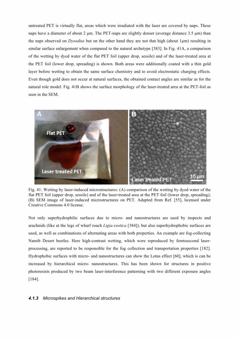
untreated PET is virtually flat, areas which were irradiated with the laser are covered by naps. These
naps have a diameter of about 2 µm. The PET-naps are slightly denser (average distance 3.5 µm) than
the naps observed on Dysodius but on the other hand they are not that high (about 1µm) resulting in
similar surface enlargement when compared to the natural archetype [383]. In Fig. 41A, a comparison
of the wetting by dyed water of the flat PET foil (upper drop, sessile) and of the laser-treated area at
the PET foil (lower drop, spreading) is shown. Both areas were additionally coated with a thin gold
layer before wetting to obtain the same surface chemistry and to avoid electrostatic charging effects.
Even though gold does not occur at natural surfaces, the obtained contact angles are similar as for the
natural role model. Fig. 41B shows the surface morphology of the laser-treated area at the PET-foil as
seen in the SEM.
Fig. 41: Wetting by laser-induced microstructures: (A) comparison of the wetting by dyed water of the flat PET foil (upper drop, sessile) and of the laser-treated area at the PET foil (lower drop, spreading); (B) SEM image of laser-induced microstructures on PET. Adapted from Ref. [55], licensed under Creative Commons 4.0 license.
Not only superhydrophilic surfaces due to micro- and nanostructures are used by inspects and
arachnids (like at the legs of wharf roach Ligia exotica [384]), but also superhydrophobic surfaces are
used, as well as combinations of alternating areas with both properties. An example are fog-collecting
Namib Desert beetles. Here high-contrast wetting, which were reproduced by femtosecond laser-
processing, are reported to be responsible for the fog collection and transportation properties [182].
Hydrophobic surfaces with micro- and nanostructures can show the Lotus effect [60], which is can be
increased by hierarchical micro- nanostructures. This has been shown for structures in positive
photoresists produced by two beam laser-interference patterning with two different exposure angles
[184].
4.1.3 Microspikes and Hierarchical structures
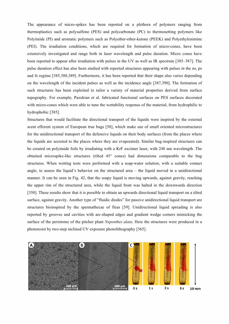
The appearance of micro-spikes has been reported on a plethora of polymers ranging from
thermoplastics such as polysulfone (PES) and polycarbonate (PC) to thermosetting polymers like
Polyimide (PI) and aromatic polymers such as Polyether-ether-ketone (PEEK) and Polyethylenimine
(PEI). The irradiation conditions, which are required for formation of micro-cones, have been
extensively investigated and range both in laser wavelength and pulse duration. Micro cones have
been reported to appear after irradiation with pulses in the UV as well as IR spectrum [385–387]. The
pulse duration effect has also been studied with reported structures appearing with pulses in the ns, ps
and fs regime [385,388,389]. Furthermore, it has been reported that their shape also varies depending
on the wavelength of the incident pulses as well as the incidence angle [387,390]. The formation of
such structures has been exploited to tailor a variety of material properties derived from surface
topography. For example, Pazokian et al. fabricated functional surfaces on PES surfaces decorated
with micro-cones which were able to tune the wettability response of the material, from hydrophilic to
hydrophobic [385].
Structures that would facilitate the directional transport of the liquids were inspired by the external
scent efferent system of European true bugs [58], which make use of small oriented microstructures
for the unidirectional transport of the defensive liquids on their body surfaces (from the places where
the liquids are secreted to the places where they are evaporated). Similar bug-inspired structures can
be created on polyimide foils by irradiating with a KrF excimer laser, with 248 nm wavelength. The
obtained microspike-like structures (tilted 45° cones) had dimensions comparable to the bug
structures. When wetting tests were performed with a soap-water solution, with a suitable contact
angle, to assess the liquid’s behavior on the structured area – the liquid moved in a unidirectional
manner. It can be seen in Fig. 42, that the soapy liquid is moving upwards, against gravity, reaching
the upper rim of the structured area, while the liquid front was halted in the downwards direction
[350]. These results show that it is possible to obtain an upwards directional liquid transport on a tilted
surface, against gravity. Another type of “fluidic diodes” for passive unidirectional liquid transport are
structures bioinspired by the spermathecae of fleas [59]. Unidirectional liquid spreading is also
reported by grooves and cavities with arc-shaped edges and gradient wedge corners mimicking the
surface of the peristome of the pitcher plant Nepenthes alata. Here the structures were produced in a
photoresist by two-step inclined UV exposure photolithography [365].
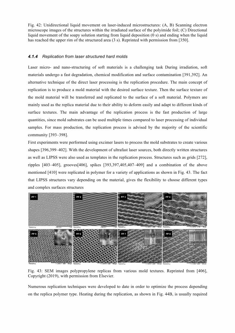
Fig. 42: Unidirectional liquid movement on laser-induced microstructures: (A, B) Scanning electron microscope images of the structures within the irradiated surface of the polyimide foil; (C) Directional liquid movement of the soapy solution starting from liquid deposition (0 s) and ending when the liquid has reached the upper rim of the structured area (3 s). Reprinted with permission from [350].
4.1.4 Replication from laser structured hard molds Laser micro- and nano-structuring of soft materials is a challenging task During irradiation, soft
materials undergo a fast degradation, chemical modification and surface contamination [391,392]. An
alternative technique of the direct laser processing is the replication procedure. The main concept of
replication is to produce a mold material with the desired surface texture. Then the surface texture of
the mold material will be transferred and replicated to the surface of a soft material. Polymers are
mainly used as the replica material due to their ability to deform easily and adapt to different kinds of
surface textures. The main advantage of the replication process is the fast production of large
quantities, since mold substrates can be used multiple times compared to laser processing of individual
samples. For mass production, the replication process is advised by the majority of the scientific
community [393–398].
First experiments were performed using excimer lasers to process the mold substrates to create various
shapes [396,399–402]. With the development of ultrafast laser sources, both directly written structures
as well as LIPSS were also used as templates in the replication process. Structures such as grids [272],
ripples [403–405], grooves[406], spikes [393,397,405,407–409] and a combination of the above
mentioned [410] were replicated in polymer for a variety of applications as shown in Fig. 43. The fact
that LIPSS structures vary depending on the material, gives the flexibility to choose different types
and complex surfaces structures
Fig. 43: SEM images polypropylene replicas from various mold textures. Reprinted from [406], Copyright (2019), with permission from Elsevier. Numerous replication techniques were developed to date in order to optimize the process depending
on the replica polymer type. Heating during the replication, as shown in Fig. 44B, is usually required
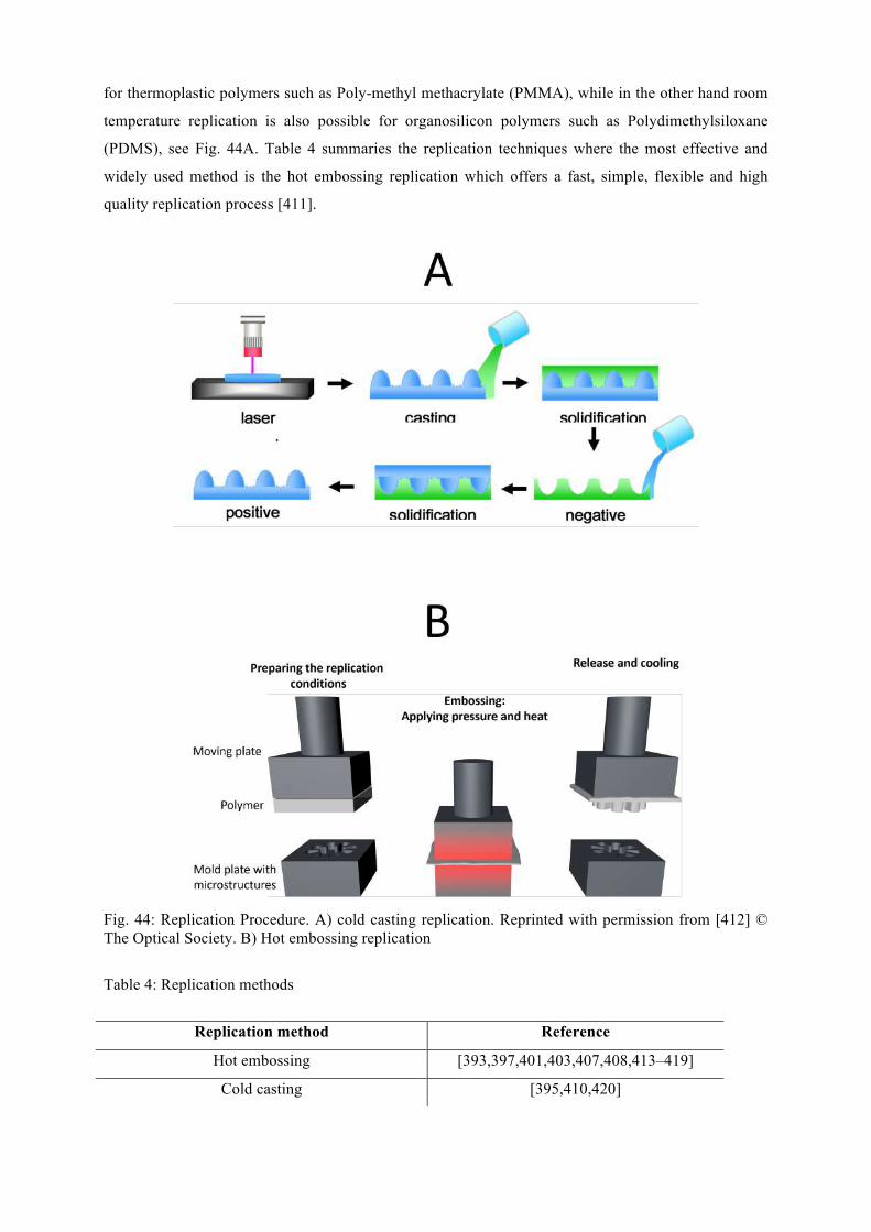
for thermoplastic polymers such as Poly-methyl methacrylate (PMMA), while in the other hand room
temperature replication is also possible for organosilicon polymers such as Polydimethylsiloxane
(PDMS), see Fig. 44A. Table 4 summaries the replication techniques where the most effective and
widely used method is the hot embossing replication which offers a fast, simple, flexible and high
quality replication process [411].
Fig. 44: Replication Procedure. A) cold casting replication. Reprinted with permission from [412] © The Optical Society. B) Hot embossing replication
Table 4: Replication methods
Replication method Reference
Hot embossing [393,397,401,403,407,408,413–419]
Cold casting [395,410,420]
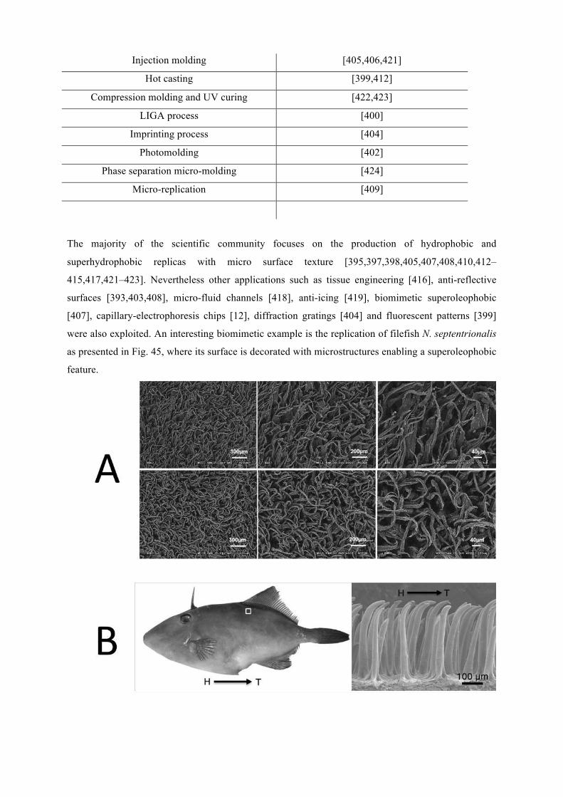
Injection molding [405,406,421]
Hot casting [399,412]
Compression molding and UV curing [422,423]
LIGA process [400]
Imprinting process [404]
Photomolding [402]
Phase separation micro-molding [424]
Micro-replication [409]
The majority of the scientific community focuses on the production of hydrophobic and
superhydrophobic replicas with micro surface texture [395,397,398,405,407,408,410,412–
415,417,421–423]. Nevertheless other applications such as tissue engineering [416], anti-reflective
surfaces [393,403,408], micro-fluid channels [418], anti-icing [419], biomimetic superoleophobic
[407], capillary-electrophoresis chips [12], diffraction gratings [404] and fluorescent patterns [399]
were also exploited. An interesting biomimetic example is the replication of filefish N. septentrionalis
as presented in Fig. 45, where its surface is decorated with microstructures enabling a superoleophobic
feature.
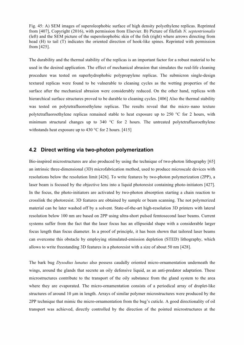
Fig. 45: A) SEM images of superoleophobic surface of high density polyethylene replicas. Reprinted from [407], Copyright (2016), with permission from Elsevier. B) Picture of filefish N. septentrionalis (left) and the SEM picture of the superoleophobic skin of the fish (right) where arrows directing from head (H) to tail (T) indicates the oriented direction of hook-like spines. Reprinted with permission from [425].
The durability and the thermal stability of the replicas is an important factor for a robust material to be
used in the desired application. The effect of mechanical abrasion that simulates the real-life cleaning
procedure was tested on superhydrophobic polypropylene replicas. The submicron single-design
textured replicas were found to be vulnerable to cleaning cycles as the wetting properties of the
surface after the mechanical abrasion were considerably reduced. On the other hand, replicas with
hierarchical surface structures proved to be durable to cleaning cycles. [406] Also the thermal stability
was tested on polytetrafluoroethylene replicas. The results reveal that the micro–nano texture
polytetrafluoroethylene replicas remained stable to heat exposure up to 250 °C for 2 hours, with
minimum structural changes up to 340 °C for 2 hours. The untreated polytetrafluoroethylene
withstands heat exposure up to 430 °C for 2 hours. [415]
4.2 Direct writing via two-photon polymerization Bio-inspired microstructures are also produced by using the technique of two-photon lithography [65]
an intrinsic three-dimensional (3D) microfabrication method, used to produce microscale devices with
resolutions below the resolution limit [426]. To write features by two-photon polymerization (2PP), a
laser beam is focused by the objective lens into a liquid photoresist containing photo-initiators [427].
In the focus, the photo-initiators are activated by two-photon absorption starting a chain reaction to
crosslink the photoresist. 3D features are obtained by sample or beam scanning. The not polymerized
material can be later washed off by a solvent. State-of-the-art high-resolution 3D printers with lateral
resolution below 100 nm are based on 2PP using ultra-short pulsed femtosecond laser beams. Current
systems suffer from the fact that the laser focus has an ellipsoidal shape with a considerable larger
focus length than focus diameter. In a proof of principle, it has been shown that tailored laser beams
can overcome this obstacle by employing stimulated-emission depletion (STED) lithography, which
allows to write freestanding 3D features in a photoresist with a size of about 50 nm [428].
The bark bug Dysodius lunatus also possess caudally oriented micro-ornamentation underneath the
wings, around the glands that secrete an oily defensive liquid, as an anti-predator adaptation. These
microstructures contribute to the transport of the oily substance from the gland system to the area
where they are evaporated. The micro-ornamentation consists of a periodical array of droplet-like
structures of around 10 µm in length. Arrays of similar polymer microstructures were produced by the
2PP technique that mimic the micro-ornamentation from the bug’s cuticle. A good directionality of oil
transport was achieved, directly controlled by the direction of the pointed microstructures at the
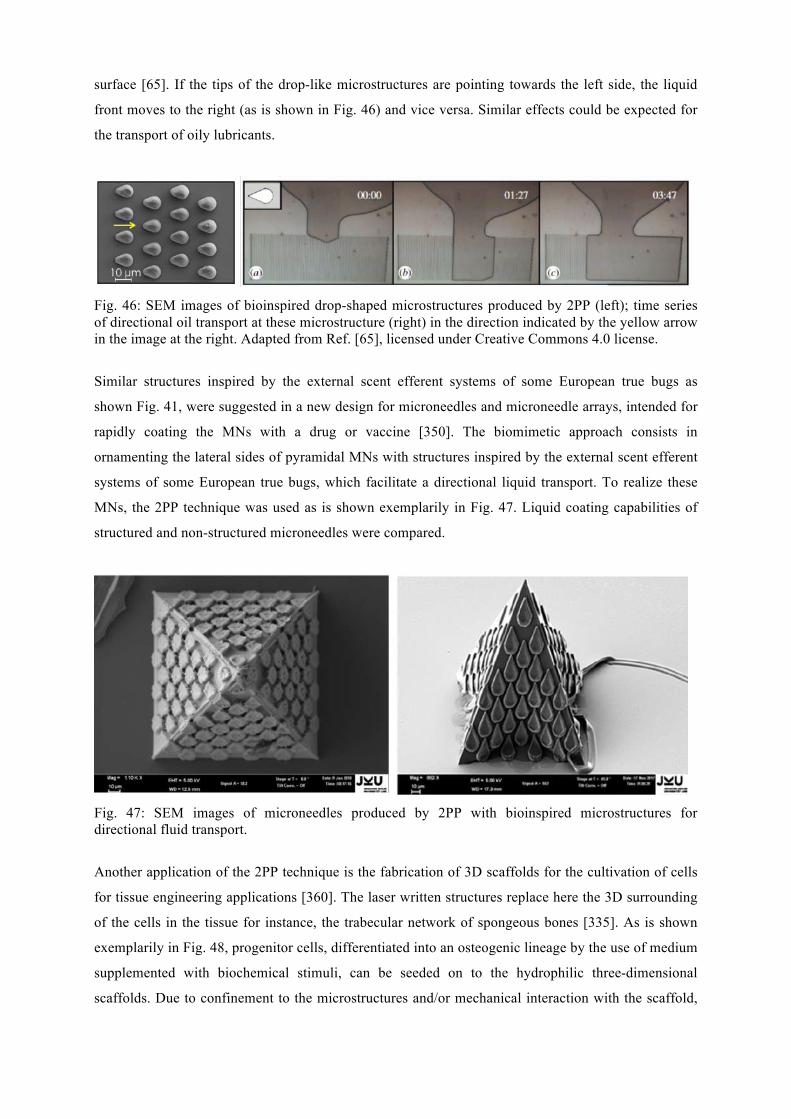
surface [65]. If the tips of the drop-like microstructures are pointing towards the left side, the liquid
front moves to the right (as is shown in Fig. 46) and vice versa. Similar effects could be expected for
the transport of oily lubricants.
Fig. 46: SEM images of bioinspired drop-shaped microstructures produced by 2PP (left); time series of directional oil transport at these microstructure (right) in the direction indicated by the yellow arrow in the image at the right. Adapted from Ref. [65], licensed under Creative Commons 4.0 license.
Similar structures inspired by the external scent efferent systems of some European true bugs as
shown Fig. 41, were suggested in a new design for microneedles and microneedle arrays, intended for
rapidly coating the MNs with a drug or vaccine [350]. The biomimetic approach consists in
ornamenting the lateral sides of pyramidal MNs with structures inspired by the external scent efferent
systems of some European true bugs, which facilitate a directional liquid transport. To realize these
MNs, the 2PP technique was used as is shown exemplarily in Fig. 47. Liquid coating capabilities of
structured and non-structured microneedles were compared.
Fig. 47: SEM images of microneedles produced by 2PP with bioinspired microstructures for directional fluid transport.
Another application of the 2PP technique is the fabrication of 3D scaffolds for the cultivation of cells
for tissue engineering applications [360]. The laser written structures replace here the 3D surrounding
of the cells in the tissue for instance, the trabecular network of spongeous bones [335]. As is shown
exemplarily in Fig. 48, progenitor cells, differentiated into an osteogenic lineage by the use of medium
supplemented with biochemical stimuli, can be seeded on to the hydrophilic three-dimensional
scaffolds. Due to confinement to the microstructures and/or mechanical interaction with the scaffold,
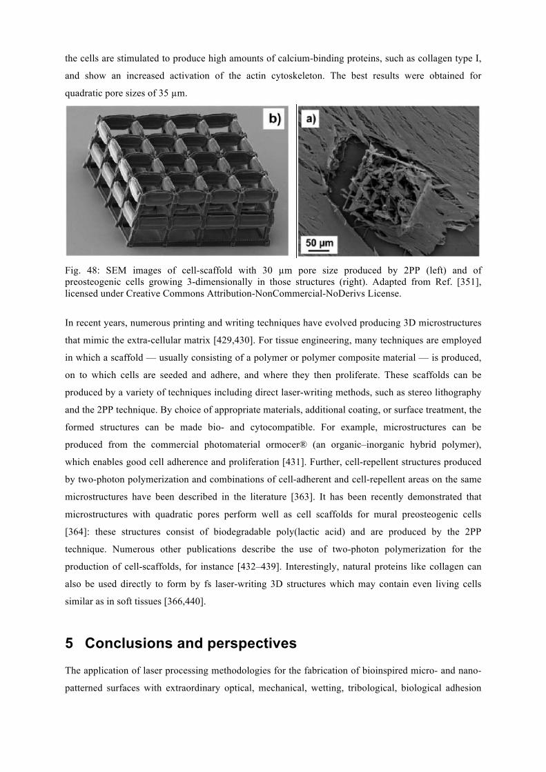
the cells are stimulated to produce high amounts of calcium-binding proteins, such as collagen type I,
and show an increased activation of the actin cytoskeleton. The best results were obtained for
quadratic pore sizes of 35 µm.
Fig. 48: SEM images of cell-scaffold with 30 µm pore size produced by 2PP (left) and of preosteogenic cells growing 3-dimensionally in those structures (right). Adapted from Ref. [351], licensed under Creative Commons Attribution-NonCommercial-NoDerivs License.
In recent years, numerous printing and writing techniques have evolved producing 3D microstructures
that mimic the extra-cellular matrix [429,430]. For tissue engineering, many techniques are employed
in which a scaffold — usually consisting of a polymer or polymer composite material — is produced,
on to which cells are seeded and adhere, and where they then proliferate. These scaffolds can be
produced by a variety of techniques including direct laser-writing methods, such as stereo lithography
and the 2PP technique. By choice of appropriate materials, additional coating, or surface treatment, the
formed structures can be made bio- and cytocompatible. For example, microstructures can be
produced from the commercial photomaterial ormocer® (an organic–inorganic hybrid polymer),
which enables good cell adherence and proliferation [431]. Further, cell-repellent structures produced
by two-photon polymerization and combinations of cell-adherent and cell-repellent areas on the same
microstructures have been described in the literature [363]. It has been recently demonstrated that
microstructures with quadratic pores perform well as cell scaffolds for mural preosteogenic cells
[364]: these structures consist of biodegradable poly(lactic acid) and are produced by the 2PP
technique. Numerous other publications describe the use of two-photon polymerization for the
production of cell-scaffolds, for instance [432–439]. Interestingly, natural proteins like collagen can
also be used directly to form by fs laser-writing 3D structures which may contain even living cells
similar as in soft tissues [366,440].
5 Conclusions and perspectives The application of laser processing methodologies for the fabrication of bioinspired micro- and nano-
patterned surfaces with extraordinary optical, mechanical, wetting, tribological, biological adhesion
and antibacterial properties has been reviewed. At the same time, the physical and biological
principles behind the exceptional functionalities exhibited by model natural surfaces, used for
inspiration, were analyzed and discussed. It was highlighted that; biological surfaces present a
virtually endless potential of technological ideas for the development of new materials and systems. In
this context, the innovative aspect of laser functionalized biomimetic surfaces for numerous current
and potential applications was particularly demonstrated.
Although current laser fabrication techniques are valuable within a limited range of applications,
the present effort is still far from the ultimate goal of realizing large-scale artificial structures that fully
mimic the architecture complexity and functionality of natural surfaces, in a convenient, rapid and
cost-effective manner. Accordingly, there are still many challenges to overcome. Indeed, to mimic the
complex hierarchical structure of natural surfaces, future fabrication methods must incorporate precise
control over different size scales in a single step, i.e. tailored fabrication of nano-features imprinted on
the surface of micro-features. Another challenge is the precision fabrication of highly complex
textures and the subsequent creation of meta-surfaces incorporating micro-/nano- features of multiple
spatial frequencies and orientations. Finally, a big challenge for laser technology is to combine both
artificially generated surface topologies with ad-hoc designed surface chemistry, as it is commonly
found in nature, in a single processing step.
To date, laser-based surface processing methods can manufacture structures at scales down to 100
nm, so there is a demand for controllable fabrication at the nanometer scale. This is one of the biggest
challenges towards engineering truly biomimetic hierarchically structured artificial surfaces and to
take full advantage of the potential of nanofeature incorporation. A key issue towards improving laser
structuring resolution is the minimization of thermal damage effects including melting, burr formation
and cracking that limit the resolution of the fabricated structures. Femtosecond (fs) lasers present
unique capabilities in this respect and it is encouraging that recent significant improvements in the fs
sources available have accelerated the acceptance of such lasers as a strong option for large-scale and
high-throughput fabrication. The lasers available today offer vastly improved peak powers and
reliability, offering the possibility to fs processing technology into a range of surface engineering
applications. Furthermore, high repetition rate fs laser systems are extensively developed and attract
much attention as new light sources due to the potential increase of the fabrication rate and thus
production throughput. Accordingly, fs laser texturing presents unique capabilities for large-scale
nanostructures production, opening new opportunities for innovation in surface functionalization and a
new paradigm in surface coatings industry.
There are also emerging aspects of laser based fabrication techniques, which may be exploited for
expanding the complexity and novelty of biomimetic textures. For example, the use of temporally
shaped ultrafast pulses may provide an additional route for controlling and optimizing the outcome of
processing. Likewise, the exploitation of filamentation effects, produced by ultrafast lasers. No doubt,
all these techniques require further development before they can become competitive. However, the
wealth of arising possibilities in laser based micro and nanofabrication and the number of new
approaches to bioinspiration prescribe a future where biomimetic control of biomimetic artificial
surfaces and subsequent functionality can be accomplished with a level of sophistication that we
cannot presently envisage.
With regard to future prospects, the coming years may primarily belong to the laser fabrication of
bioinspired multifunctional surfaces, i.e, surfaces that combine multiple functionalities.
Multifunctional surfaces are important for a broad range of applications in engineering sciences,
including adhesion, friction, wear, lubrication, filtering, sensorics, wetting phenomena, self-cleaning,
antifouling, thermoregulation, optics, to name a few. Research on responsive and intelligent materials,
combined with the use of the principles of evolution for optimization, is expected to give rise to
multifunctional biomimetic surfaces that currently remain beyond our grasp. No doubt, research in this
field involves synergies from biology, physics, chemistry, materials science and engineering and
therefore represents an excellent example of modern interdisciplinary science.
6 Acknowledgements This work was supported by the European Union’s Horizon 2020 research and innovation program
through the project “BioCombs4Nanofibers” [grant agreement No. 862016] and “BioProMarL” [grant
agreement No. 852048], the Excellence Initiative of the German federal and state governments and the
Spanish Research Agency (AEI, Ministry of Research and Innovation) jointly with the European
Regional Development Fund (ERDF) through project “UDiSON [grant No. TEC2017-82464-R].
7 References [1] T.C.Barr,J.R.Holsinger,Annu.Rev.Ecol.Syst.16(1985)313–337.
[2] S.Mammola,M.Isaia,Proc.R.Soc.BBiol.Sci.284(2017)20170193.
[3] L.Deharveng,A.Bedos,in:O.T.Moldovan,Ľ.Kováč,S.Halse(Eds.),Springer
InternationalPublishing,Cham,2018,pp.107–172.
[4] V.Welch,V.Lousse,O.Deparis,A.Parker,J.P.Vigneron,Phys.Rev.E75(2007)
041919.
[5] B.-K.Hsiung,R.H.Siddique,D.G.Stavenga,J.C.Otto,M.C.Allen,Y.Liu,Y.-F.Lu,D.D.
Deheyn,M.D.Shawkey,T.A.Blackledge,Nat.Commun.8(2017)2278.
[6] R.H.Siddique,G.Gomard,H.Hölscher,Nat.Commun.6(2015)6909.
[7] A.Papadopoulos,E.Skoulas,A.Mimidis,G.Perrakis,G.Kenanakis,G.D.Tsibidis,E.
Stratakis,Adv.Mater.(2019)1901123.
[8] P.Vukusic,J.R.Sambles,Nature424(2003)852.
[9] Aristotle,TheHistoryofAnimals,BookIX,n.d.
[10] R.Hooke,Micrographia,TheRoyalSociety,London,1665.
[11] I.Newton,ATreatiseoftheReflections,Refractions,InflectionsandColoursof
Light,4thed.,1730.
[12] F.E.Beddard,AnimalColoration;anAccountofthePrincipalFactsandTheories
RelatingtotheColoursandMarkingsofAnimals.ByFrankE.Beddard,S.
Sonnenschein&co.,London,1892.
[13] S.D.Finkbeiner,A.D.Briscoe,R.D.Reed,Evolution(N.Y).68(2014)3410–3420.
[14] M.B.Girard,M.M.Kasumovic,D.O.Elias,PLoSOne6(2011)e25390.
[15] B.D.Wilts,K.Michielsen,H.DeRaedt,D.G.Stavenga,Proc.Natl.Acad.Sci.111
(2014)4363–4368.
[16] D..Stavenga,S.Foletti,G.Palasantzas,K.Arikawa,Proc.R.Soc.BBiol.Sci.273
(2006)661–667.
[17] K.Valenta,O.Nevo,C.Martel,C.A.Chapman,Evol.Ecol.31(2017)249–267.
[18] T.B.H.Schroeder,J.Houghtaling,B.D.Wilts,M.Mayer,Adv.Mater.30(2018)
1705322.
[19] K.Kjernsmo,H.M.Whitney,N.E.Scott-Samuel,J.R.Hall,H.Knowles,L.Talas,I.C.
Cuthill,Curr.Biol.30(2020)551-555.e3.
[20] P.R.Stoddart,P.J.Cadusch,T.M.Boyce,R.M.Erasmus,J.D.Comins,Nanotechnology
17(2006)680–686.
[21] D.E.McCoy,T.Feo,T.A.Harvey,R.O.Prum,Nat.Commun.9(2018)1.
[22] J.Morikawa,M.Ryu,G.Seniutinas,A.Balčytis,K.Maximova,X.Wang,M.Zamengo,
E.P.Ivanova,S.Juodkazis,Langmuir32(2016)4698–4703.
[23] A.R.Parker,R.C.Mcphedran,Nature409(2001)36–37.
[24] A.R.Parker,H.E.Townley,Nanosci.Technol.ACollect.Rev.fromNat.Journals
(2009)230–238.
[25] P.Vukusic,D..Stavenga,J.R.Soc.Interface6(2009)S133–S148.
[26] A.R.Parker,J.Exp.Biol.201(1998)2343–2347.
[27] A.R.Parker,N.Martini,Opt.LaserTechnol.38(2006)315–322.
[28] S.Kinoshita,S.Yoshioka,J.Miyazaki,ReportsProg.Phys.71(2008)076401.
[29] J.Sun,B.Bhushan,J.Tong,RSCAdv.3(2013)14862.
[30] Z.W.Han,Z.Wang,X.M.Feng,B.Li,Z.Z.Mu,J.Q.Zhang,S.C.Niu,L.Q.Ren,Biosurface
andBiotribology2(2016)137–150.
[31] D.E.McCoy,V.E.McCoy,N.K.Mandsberg,A.V.Shneidman,J.Aizenberg,R.O.Prum,
D.Haig,Proc.R.Soc.BBiol.Sci.286(2019)20190589.
[32] S.Chattopadhyay,Y.F.Huang,Y.J.Jen,A.Ganguly,K.H.Chen,L.C.Chen,Mater.Sci.
Eng.R69(2010)1–35.
[33] J.C.M.Garnett,Philos.Trans.R.Soc.London205(1906)237.
[34] D.A.G.Bruggeman,Ann.Phys.416(1935)636.
[35] R.O.Prum,Integr.Comp.Biol.43(2003)591–602.
[36] Y.Yue,J.P.Gong,J.Photochem.Photobiol.CPhotochem.Rev.23(2015)45–67.
[37] J.P.Vigneron,P.Simonis,Phys.BCondens.Matter407(2012)4032–4036.
[38] J.Cai,L.Qi,Mater.Horizons2(2015)37–53.
[39] N.Bonod,J.Neauport,Adv.Opt.Photonics8(2016)156.
[40] C.S.Law,L.F.Marsal,A.Santos,in:Handb.Nanomater.Anal.Chem.,Elsevier,2020,
pp.201–226.
[41] S.Niu,B.Li,Z.Mu,M.Yang,J.Zhang,Z.Han,L.Ren,12(2015)170–189.
[42] B.D.Wilts,V.Saranathan,Small14(2018)1802328.
[43] B.-K.Hsiung,R.H.Siddique,L.Jiang,Y.Liu,Y.Lu,M.D.Shawkey,T.A.Blackledge,
Adv.Opt.Mater.5(2017)1600599.
[44] V.L.Welch,J.-P.Vigneron,Opt.QuantumElectron.39(2007)295–303.
[45] V.R.Binetti,J.D.Schiffman,O.D.Leaffer,J.E.Spanier,C.L.Schauer,Integr.Biol.1
(2009)324.
[46] M.D.Cardwell,Herpetol.Rev.37(2006)142–144.
[47] A.M.Rijke,J.Exp.Biol.56(1972)195–200.
[48] W.F.C.Blumer,C.Gans,R.Merlin,Amphibia-Reptilia3(1982)57–64.
[49] H.B.Lillywhite,P.Licht,Copeia1974(1974)165.
[50] H.B.Lillywhite,B.R.Stein,J.Zool.211(1987)727–734.
[51] G.N.Louw,in:Symp.Zool.Soc.London,1972,pp.297–314.
[52] W.C.Sherbrooke,J.Herpetol.24(1990)302.
[53] C.R.Tracy,N.Laurence,K.A.Christian,Am.Nat.178(2011)553–558.
[54] K.Koch,B.Bhushan,W.Barthlott,Prog.Mater.Sci.54(2009)137–178.
[55] F.Hischen,V.Reiswich,D.Kupsch,N.DeMecquenem,M.Riedel,M.Himmelsbach,
A.Weth,E.Heiss,O.Armbruster,J.Heitz,W.Baumgartner,Biol.Open6(2017)
1209–1218.
[56] P.Comanns,G.Buchberger,A.Buchsbaum,R.Baumgartner,A.Kogler,S.Bauer,W.
Baumgartner,J.R.Soc.Interface12(2015)20150415.
[57] M.Yenmiş,D.Ayaz,W.C.Sherbrooke,M.Veselý,Zoomorphology135(2016)137–
148.
[58] F.Hischen,G.Buchberger,C.Plamadeala,O.Armbruster,E.Heiss,K.Winands,M.
Schwarz,B.Jüttler,J.Heitz,W.Baumgartner,J.R.Soc.Interface15(2018)
20170975.
[59] G.Buchberger,A.Kogler,A.Weth,R.Baumgartner,P.Comanns,S.Bauer,W.
Baumgartner,J.BionicEng.15(2018)42–56.
[60] W.Barthlott,C.Neinhuis,Planta202(1997)1–8.
[61] P.Comanns,K.Winands,M.Pothen,R.A.Bott,H.Wagner,W.Baumgartner,in:
Proc.SPIE9797,2016,p.979711.
[62] G.Buchberger,F.Hischen,P.Comanns,R.Baumgartner,A.Kogler,A.Buchsbaum,
S.Bauer,W.Baumgartner,ProcediaEng.120(2015)106–111.
[63] P.Comanns,K.Winands,K.Arntz,F.Klocke,W.Baumgartner,Int.J.Des.Nat.
Ecodynamics9(2014)206–215.
[64] U.Hermens,S.V.Kirner,C.Emonts,P.Comanns,E.Skoulas,A.Mimidis,H.
Mescheder,K.Winands,J.Krüger,E.Stratakis,J.Bonse,Appl.Surf.Sci.418(2017)
499–507.
[65] C.Plamadeala,F.Hischen,R.Friesenecker,R.Wollhofen,J.Jacak,G.Buchberger,E.
Heiss,T.A.Klar,W.Baumgartner,J.Heitz,R.Soc.OpenSci.4(2017)160849.
[66] W.Barthlott,M.Mail,C.Neinhuis,Philos.Trans.R.Soc.AMath.Phys.Eng.Sci.374
(2016)20160191.
[67] V.R.Gray,in:Chem.Ind.,1965,p.969.
[68] J.C.Moore,A.Kazachkov,A.G.Anders,C.Willis,InformalLearn.PublicUnderst.Sci.
(2005)399–404.
[69] E.Y.Bormashenko,WettingofRealSurfaces,WalterdeGruyterGmbH&CoKG,
2013.
[70] T.Young,Philos.Trans.R.Soc.London95(1805)65–87.
[71] R.N.Wenzel,Ind.Eng.Chem.28(1936)988–994.
[72] A.B.D.Cassie,S.Baxter,Trans.FaradaySoc.40(1944)546.
[73] M.Nosonovsky,B.Bhushan,Ultramicroscopy107(2007)969–979.
[74] J.N.Israelachvili,IntermolecularandSurfaceForces,3rded.,Elsevier,Amsterdam,
2011.
[75] L.D.Landau,E.M.Lifshitz,FluidMechanics,2ndEditio,Elsevier,Oxford,UK,1987.
[76] M.A.Meyers,P.-Y.Chen,A.Y.-M.Lin,Y.Seki,Prog.Mater.Sci.53(2008)1–206.
[77] B.Bhushan,Philos.Trans.R.Soc.AMath.Phys.Eng.Sci.367(2009)1445–1486.
[78] B.Bhushan,Y.C.Jung,Prog.Mater.Sci.56(2011)1–108.
[79] K.Autumn,Y.A.Liang,S.T.Hsieh,W.Zesch,W.P.Chan,T.W.Kenny,R.Fearing,R.J.
Full,Nature405(2000)681–685.
[80] H.Gao,X.Wang,H.Yao,S.Gorb,E.Arzt,Mech.Mater.37(2005)275–285.
[81] A.Malshe,K.Rajurkar,A.Samant,H.N.Hansen,S.Bapat,W.Jiang,CIRPAnn.62
(2013)607–628.
[82] T.W.Kim,B.Bhushan,J.Adhes.Sci.Technol.21(2007)1–20.
[83] K.Autumn,M.Sitti,Y.A.Liang,A.M.Peattie,W.R.Hansen,S.Sponberg,T.W.Kenny,
R.Fearing,J.N.Israelachvili,R.J.Full,Proc.Natl.Acad.Sci.99(2002)12252–
12256.
[84] K.L.Johnson,K.Kendall,A.D.Roberts,Proc.R.Soc.London.A.Math.Phys.Sci.324
(1971)301–313.
[85] E.Arzt,S.Gorb,R.Spolenak,Proc.Natl.Acad.Sci.100(2003)10603–10606.
[86] B.N.J.Persson,J.Chem.Phys.118(2003)7614.
[87] P.M.Favi,S.Yi,S.C.Lenaghan,L.Xia,M.Zhang,J.Adhes.Sci.Technol.28(2014)
290–319.
[88] S.S.F.Geiselhardt,W.Federle,B.Prüm,S.S.F.Geiselhardt,S.Lamm,K.Peschke,J.
InsectPhysiol.56(2010)398–404.
[89] S.N.Gorb,M.Sinha,A.Peressadko,K.A.Daltorio,R.D.Quinn,Bioinspir.Biomim.2
(2007)S117–S125.
[90] W.Federle,J.Exp.Biol.209(2006)2611–2621.
[91] S.Gorb,AttachmentDevicesofInsectCuticle,KluwerAcademicPublishers,
Dordrecht,2002.
[92] M.Scherge,S.S.Gorb,BiologicalMicro-andNanotribology,Springer,Berlin,
Heidelberg,2001.
[93] J.M.R.R.Bullock,P.Drechsler,W.Federle,J.Exp.Biol.211(2008)3333–3343.
[94] J.S.Edwards,M.Tarkanian,Proc.R.Entomol.Soc.London.Ser.A,Gen.Entomol.45
(2009)1–5.
[95] G.Walker,A.B.Yulf,J.Ratcliffe,J.Zool.205(1985)297–307.
[96] S.ISHII,Appl.Entomol.Zool.22(1987)222–228.
[97] A.KOSAKI,R.YAMAOKA,JapaneseJ.Appl.Entomol.Zool.40(1996)47–53.
[98] T.Eisner,D.J.Aneshansley,Proc.Natl.Acad.Sci.97(2000)6568–6573.
[99] W.Federle,W.J..J.P.Barnes,W.Baumgartner,P.Drechsler,J..M.Smith,J.R.Soc.
Interface3(2006)689–697.
[100]S.B.Emerson,D.Diehl,Biol.J.Linn.Soc.13(1980)199–216.
[101]I.Scholz,W.J.P.Barnes,J.M.Smith,W.Baumgartner,J.Exp.Biol.212(2009)155–
162.
[102]A.Ohler,Asiat.Herpetol.Res.6(1995)85–96.
[103]W.J.P.Barnes,MRSBull.32(2007)479–485.
[104]E.J.DeSouza,M.Brinkmann,C.Mohrdieck,E.Arzt,Langmuir24(2008)8813–
8820.
[105]H.A.Abdel-Aal,J.Mech.Behav.Biomed.Mater.79(2018)354–398.
[106]J.Hazel,M.Stone,M..S.Grace,V..V.Tsukruk,J.Biomech.32(1999)477–484.
[107]H.Huang,Y.Zhang,L.Ren,J.BionicEng.9(2012)465–469.
[108]M.-C.G.Klein,S.N.Gorb,J.R.Soc.Interface9(2012)3140–3155.
[109]H.A.Abdel-Aal,J.Mech.Behav.Biomed.Mater.22(2013)115–135.
[110]M.J.Benz,A.E.Kovalev,S.N.Gorb,in:Proc.SPIE8339,2012,p.83390X.
[111]M.J.Baum,L.Heepe,E.Fadeeva,S.N.Gorb,BeilsteinJ.Nanotechnol.5(2014)
1091–1103.
[112]P.F.A.Maderson,T.Rabinowitz,B.Tandler,L.Alibardi,J.Morphol.236(1998)1–
24.
[113]M.Toni,L.Alibardi,Zoology110(2007)41–47.
[114]M.Toni,L.DallaValle,L.Alibardi,J.ProteomeRes.6(2007)3377–3392.
[115]M.-C.G.Klein,S.N.Gorb,Zoology117(2014)295–314.
[116]A.E.Filippov,S.N.Gorb,Sci.Rep.6(2016)23539.
[117]B.Dean,B.Bhushan,Philos.Trans.R.Soc.AMath.Phys.Eng.Sci.368(2010)
4775–4806.
[118]D.W.Bechert,M.Bruse,W.Hage,Exp.Fluids28(2000)403–412.
[119]D.W.Bechert,M.Bruse,W.Hage,J.G.T.T.VanDerHoeven,G.Hoppe,J.FluidMech.
338(1997)59–87.
[120]J.Oeffner,G.V.Lauder,J.Exp.Biol.215(2012)785–795.
[121]S.K.Robinson,TheKinematicsofTurbulentBoundaryLayerStructure,Stanford
University,1991.
[122]S.-J.Lee,S.-H.Lee,Exp.Fluids30(2001)153–166.
[123]A.P.Jackson,J.F.V.Vincent,andR.M.Turner,Proc.R.Soc.London.Ser.B.Biol.Sci.
234(1988)415–440.
[124]I.A.Aksay,M.Trau,S.Manne,I.Honma,N.Yao,L.Zhou,P.Fenter,P.M.Eisenberger,
S.M.Gruner,Science,273(1996)892–898.
[125]B.L.Smith,T.E.Schäffer,M.Viani,J.B.Thompson,N.A.N.A.Frederick,J.Kindt,A.
Belcher,G.D.Stucky,D.E.Morse,P.K.Hansma,M.Vlani,J.B.Thompson,N.A.N.A.
Frederick,J.Klndt,A.Belcher,G.D.Stucky,D.E.Morse,P.K.Hansma,Nature399
(1999)761–763.
[126]F.Barthelat,Philos.Trans.R.Soc.AMath.Phys.Eng.Sci.365(2007)2907–2919.
[127]Z.Tang,N.A.Kotov,S.Magonov,B.Ozturk,Nat.Mater.2(2003)413–418.
[128]P.Podsiadlo,A.K.Kaushik,E.M.Arruda,A.M.Waas,B.S.Shim,J.Xu,H.Nandivada,
B.G.Pumplin,J.Lahann,A.Ramamoorthy,N.A.Kotov,Science(80-.).318(2007)
80–83.
[129]L.J.Bonderer,A.R.Studart,L.J.Gauckler,Science(80-.).319(2008)1069–1073.
[130]N.Holten-Andersen,G.E.Fantner,S.Hohlbauch,J.H.Waite,F.W.Zok,Nat.Mater.6
(2007)669–672.
[131]E.I.Stratakis,V.Zorba,in:NanotechnologiesLifeSci.,Wiley-VCHVerlagGmbH&
Co.KGaA,Weinheim,Germany,2012.
[132]B.T.Scheer,Biol.Bull.89(1945)103–121.
[133]M.P.Schultz,G.W.Swain,Biofouling15(2000)129–139.
[134]W.H.O.Institution,U.S.N.D.B.ofShips,MarineFoulingandItsPrevention,United
StatesNavalInstitute,1952.
[135]J.Ma,Y.Sun,K.Gleichauf,J.Lou,Q.Li,Langmuir27(2011)10035–10040.
[136]G.D.Bixler,B.Bhushan,SoftMatter8(2012)11271.
[137]W.K.Smith,T.M.McClean,Am.J.Bot.76(1989)465–469.
[138]T.Heckenthaler,S.Sadhujan,Y.Morgenstern,P.Natarajan,M.Bashouti,Y.
Kaufman,Langmuir35(2019)15526–15534.
[139]A..Bers,G..Prendergast,C..Zürn,L.Hansson,R..Head,J..Thomason,Biol.Lett.2
(2006)88–91.
[140]A.V.Bers,E.R.Díaz,B.A.P.daGama,F.Vieira-Silva,S.Dobretsov,N.Valdivia,M.
Thiel,A.J.Scardino,C.D.McQuaid,H.E.Sudgen,J.C.Thomason,M.Wahl,Biofouling
26(2010)367–377.
[141]J.D.Mckenzie,I.VGrigolava,Biofouling10(1996)261–272.
[142]H.Chen,X.Zhang,L.Ma,D.Che,D.Zhang,T.S.Sudarshan,Appl.Surf.Sci.316
(2014)124–131.
[143]G.D.Bixler,B.Bhushan,Adv.Funct.Mater.23(2013)4507–4528.
[144]Y.L.Peng,C.G.Lin,L.Wang,Adv.Mater.Res.79–82(2009)977–980.
[145]D.E.Mainwaring,S.H.Nguyen,H.Webb,T.Jakubov,M.Tobin,R.N.Lamb,A.H.-F.
Wu,R.Marchant,R.J.Crawford,E.P.Ivanova,Nanoscale8(2016)6527–6534.
[146]C.D.Bandara,S.Singh,I.O.Afara,A.Wolff,T.Tesfamichael,K.Ostrikov,A.Oloyede,
ACSAppl.Mater.Interfaces9(2017)6746–6760.
[147]E.Hoppmann,H.W.Barron,J.Exot.PetMed.16(2007)210–224.
[148]K.Nowlin,A.Boseman,A.Covell,D.LaJeunesse,J.R.Soc.Interface12(2015)
20140999.
[149]E.P.Ivanova,J.Hasan,H.K.Webb,V.K.Truong,G.S.Watson,J.A.Watson,V.A.
Baulin,S.Pogodin,J.Y.Wang,M.J.Tobin,C.Löbbe,R.J.Crawford,Small8(2012)
2489–2494.
[150]J.Hasan,H.K.Webb,V.K.Truong,S.Pogodin,V.A.Baulin,G.S.Watson,J.A.Watson,
R.J.Crawford,E.P.Ivanova,Appl.Microbiol.Biotechnol.97(2013)9257–9262.
[151]S.M.Kelleher,O.Habimana,J.Lawler,B.O’Reilly,S.Daniels,E.Casey,A.Cowley,
ACSAppl.Mater.Interfaces8(2016)14966–14974.
[152]G.S.Watson,D.W.Green,B.W.Cribb,C.L.Brown,C.R.Meritt,M.J.Tobin,J.
Vongsvivut,M.Sun,A.-P.Liang,J.A.Watson,ACSAppl.Mater.Interfaces9(2017)
24381–24392.
[153]G.S.Watson,D.W.Green,L.Schwarzkopf,X.Li,B.W.Cribb,S.Myhra,J.A.Watson,
ActaBiomater.21(2015)109–122.
[154]X.Li,G.S.Cheung,G.S.Watson,J.A.Watson,S.Lin,L.Schwarzkopf,D.W.Green,
Nanoscale8(2016)18860–18869.
[155]K.Bush,P.Courvalin,G.Dantas,J.Davies,B.Eisenstein,P.Huovinen,G.A.Jacoby,R.
Kishony,B.N.Kreiswirth,E.Kutter,S.A.Lerner,S.Levy,K.Lewis,O.Lomovskaya,
J.H.Miller,S.Mobashery,L.J.V.Piddock,S.Projan,C.M.Thomas,A.Tomasz,P.M.
Tulkens,T.R.Walsh,J.D.Watson,J.Witkowski,W.Witte,G.Wright,P.Yeh,H.I.
Zgurskaya,Nat.Rev.Microbiol.9(2011)894–896.
[156]A.Elbourne,R.J.Crawford,E.P.Ivanova,J.ColloidInterfaceSci.508(2017)603–
616.
[157]X.Li,Phys.Chem.Chem.Phys.18(2016)1311–1316.
[158]S.Pogodin,J.Hasan,V.A.Baulin,H.K.Webb,V.K.Truong,T.H.PhongNguyen,V.
Boshkovikj,C.J.Fluke,G.S.Watson,J.A.Watson,R.J.Crawford,E.P.Ivanova,
Biophys.J.104(2013)835–840.
[159]G.S.Watson,D.W.Green,J.A.Watson,Z.Zhou,X.Li,G.S.P.Cheung,M.Gellender,
Adv.Mater.Interfaces6(2019)1801646.
[160]F.Xue,J.Liu,L.Guo,L.Zhang,Q.Li,J.Theor.Biol.385(2015)1–7.
[161]D.R.Absolom,F.V.Lamberti,Z.Policova,W.Zingg,C.J.vanOss,A.W.Neumann,
Appl.Environ.Microbiol.46(1983)90–97.
[162]J.J.Thwaites,U.C.Surana,J.Bacteriol.173(1991)197–203.
[163]J.Yang,F.Luo,T.S.Kao,X.Li,G.W.Ho,J.Teng,X.Luo,M.Hong,LightSci.Appl.3
(2014)e185–e185.
[164]V.Zorba,E.Stratakis,M.Barberoglou,E.Spanakis,P.Tzanetakis,S.H.Anastasiadis,
C.Fotakis,Adv.Mater.20(2008)4049–4054.
[165]V.Zorba,E.Stratakis,M.Barberoglou,E.Spanakis,P.Tzanetakis,C.Fotakis,Appl.
Phys.A93(2008)819.
[166]C.FlorianBaron,A.Mimidis,D.Puerto,E.Skoulas,E.Stratakis,J.Solis,J.Siegel,
BeilsteinJ.Nanotechnol.9(2018)2802–2812.
[167]E.Skoulas,A.Manousaki,C.Fotakis,E.Stratakis,Sci.Rep.7(2017)45114.
[168]R.Jagdheesh,M.Diaz,J.L.Ocaña,RSCAdv.6(2016)72933–72941.
[169]Y.Liu,X.Yin,J.Zhang,Y.Wang,Z.Han,L.Ren,Appl.Surf.Sci.280(2013)845–849.
[170]Y.Liu,S.Li,S.Niu,X.Cao,Z.Han,L.Ren,Appl.Surf.Sci.379(2016)230–237.
[171]S.V.Kirner,U.Hermens,A.Mimidis,E.Skoulas,C.Florian,F.Hischen,C.
Plamadeala,W.Baumgartner,K.Winands,H.Mescheder,J.Krüger,J.Solis,J.Siegel,
E.Stratakis,J.Bonse,Appl.Phys.A123(2017)754.
[172]J.Schneider,V.Djamiykov,C.Greiner,BeilsteinJ.Nanotechnol.9(2018)2561–
2572.
[173]C.Greiner,M.Schäfer,Bioinspir.Biomim.10(2015)044001.
[174]T.Chen,H.Liu,H.Yang,W.Yan,W.Zhu,H.Liu,RSCAdv.6(2016)43937–43949.
[175]C.Lanara,A.Mimidis,E.Stratakis,Materials(Basel).12(2019)3428.
[176]H.Zhou,N.Sun,H.Shan,D.Ma,X.Tong,L.Ren,Appl.Surf.Sci.253(2007)9513–
9520.
[177]D.Cong,H.Zhou,Z.Ren,Z.Zhang,H.Zhang,C.Meng,C.Wang,Mater.Des.55
(2014)597–604.
[178]D.Cong,H.Zhou,M.Yang,Z.Zhang,P.Zhang,C.Meng,C.Wang,Opt.LaserTechnol.
53(2013)1–8.
[179]Y.Liu,X.Li,J.Jin,J.Liu,Y.Yan,Z.Han,L.Ren,Appl.Surf.Sci.400(2017)498–505.
[180]E.Fadeeva,V.K.Truong,M.Stiesch,B.N.Chichkov,R.J.Crawford,J.Wang,E.P.
Ivanova,Langmuir27(2011)3012–3019.
[181]A.H.A.Lutey,L.Gemini,L.Romoli,G.Lazzini,F.Fuso,M.Faucon,R.Kling,Sci.Rep.
8(2018)10112.
[182]E.Kostal,S.Stroj,S.Kasemann,V.Matylitsky,M.Domke,Langmuir34(2018)
2933–2941.
[183]J.Lu,C.-V.Ngo,S.C.Singh,J.Yang,W.Xin,Z.Yu,C.Guo,Langmuir35(2019)3562–
3567.
[184]M.-N.Liu,L.Wang,Y.-H.Yu,A.-W.Li,Opt.Mater.Express7(2017)2208.
[185]J.-M.Romano,R.Helbig,F.Fraggelakis,A.Garcia-Giron,C.Werner,R.Kling,S.
Dimov,J.MicroNano-Manufacturing7(2019)024504.
[186]Z.Zhan,M.ElKabbash,J.Cheng,J.Zhang,S.Singh,C.Guo,ACSAppl.Mater.
Interfaces11(2019)48512–48517.
[187]C.Simitzi,P.Efstathopoulos,A.Kourgiantaki,A.Ranella,I.Charalampopoulos,C.
Fotakis,I.Athanassakis,E.Stratakis,A.Gravanis,Biomaterials67(2015)115–128.
[188]C.Li,Y.Yang,L.Yang,Z.Shi,Micromachines10(2019)816.
[189]C.Yiannakou,C.Simitzi,A.Manousaki,C.Fotakis,A.Ranella,E.Stratakis,
Biofabrication9(2017)025024.
[190]W.Liu,P.Fan,M.Cai,X.Luo,C.Chen,R.Pan,H.Zhang,M.Zhong,Nanoscale11
(2019)8940–8949.
[191]E.Stratakis,A.Ranella,C.Fotakis,Biomicrofluidics5(2011)013411.
[192]K.Ahmmed,C.Grambow,A.-M.Kietzig,Micromachines5(2014)1219–1253.
[193]A.Borowiec,H.K.Haugen,Appl.Phys.Lett.82(2003)4462–4464.
[194]J.Bonse,S.Hohm,S.V.Kirner,A.Rosenfeld,J.Kruger,IEEEJ.Sel.Top.Quantum
Electron.23(2017)9000615.
[195]M.Barberoglou,D.Gray,E.Magoulakis,C.Fotakis,P.A.Loukakos,E.Stratakis,Opt.
Express21(2013)18501.
[196]S.Höhm,A.Rosenfeld,J.Krüger,J.Bonse,J.Appl.Phys.112(2012)014901.
[197]G.D.Tsibidis,E.Skoulas,A.Papadopoulos,E.Stratakis,Phys.Rev.B94(2016)
081305.
[198]E.Stratakis,Sci.Adv.Mater.4(2012)407–431.
[199]F.Müller,C.Kunz,S.Gräf,Materials,9(2016)476.
[200]E.Fadeeva,B.Chichkov,Appl.Sci.8(2018)1424.
[201]J.Zhang,F.Chen,J.Yong,Q.Yang,X.Hou,LaserOptoelectron.Prog.55(2018)
110001.
[202]J.Yong,Q.Yang,C.Guo,F.Chen,X.Hou,RSCAdv.9(2019)12470–12495.
[203]J.E.Sipe,J.F.Young,J.S.Preston,H.M.vanDriel,Phys.Rev.B27(1983)1141–1154.
[204]J.Bonse,A.Rosenfeld,J.Krüger,J.Appl.Phys.106(2009)104910.
[205]T.Y.Hwang,C.Guo,J.Appl.Phys.108(2010)073523.
[206]J.Bonse,M.Munz,H.Sturm,J.Appl.Phys.97(2005)013538.
[207]J.Bonse,J.Krüger,S.Höhm,A.Rosenfeld,J.LaserAppl.24(2012)042006.
[208]Y.Fuentes-Edfuf,J.A.Sánchez-Gil,C.Florian,V.Giannini,J.Solis,J.Siegel,ACS
Omega4(2019)6939–6946.
[209]X.Sedao,A.AbouSaleh,A.Rudenko,T.Douillard,C.Esnouf,S.Reynaud,C.
Maurice,F.Pigeon,F.Garrelie,J.-P.Colombier,ACSPhotonics5(2018)1418–
1426.
[210]Y.Fuentes-Edfuf,J.A.Sánchez-Gil,M.Garcia-Pardo,R.Serna,G.D.Tsibidis,V.
Giannini,J.Solis,J.Siegel,Appl.Surf.Sci.493(2019)948–955.
[211]M.Huang,F.Zhao,Y.Cheng,N.Xu,Z.Xu,ACSNano3(2009)4062–4070.
[212]D.Puerto,M.Garcia-Lechuga,J.Hernandez-Rueda,A.Garcia-Leis,S.Sanchez-
Cortes,J.Solis,J.Siegel,Nanotechnology27(2016)265602.
[213]Y.Fuentes-Edfuf,M.Garcia-Lechuga,D.Puerto,C.Florian,A.Garcia-Leis,S.
Sanchez-Cortes,J.Solis,J.Siegel,Sci.Rep.7(2017)4594.
[214]M.Soileau,IEEEJ.QuantumElectron.20(1984)464–467.
[215]J.Bonse,S.V.Kirner,S.Höhm,N.Epperlein,D.Spaltmann,A.Rosenfeld,J.Krüger,
ProcSPIE10092(2017)100920N.
[216]A.Rudenko,J.-P.Colombier,S.Höhm,A.Rosenfeld,J.Krüger,J.Bonse,T.E.Itina,
Sci.Rep.7(2017)12306.
[217]J.Heitz,E.Arenholz,D.Bauerle,R.Sauerbrey,H.M.Phillips,Appl.Phys.A59
(1994)289–293.
[218]G.Miyaji,K.Miyazaki,Opt.Express16(2008)16265.
[219]G.D.Tsibidis,M.Barberoglou,P.A.Loukakos,E.Stratakis,C.Fotakis,Phys.Rev.B
86(2012)115316.
[220]S.Höhm,A.Rosenfeld,J.Krüger,J.Bonse,Appl.Phys.Lett.102(2013)054102.
[221]J.Z.P.Skolski,G.R.B.E.Römer,J.V.Obona,V.Ocelik,A.J.Huisin’tVeld,J.T.M.De
Hosson,Phys.Rev.B85(2012)075320.
[222]G.D.Tsibidis,A.Mimidis,E.Skoulas,S.V.Kirner,J.Krüger,J.Bonse,E.Stratakis,
Appl.Phys.A124(2018)27.
[223]G.D.Tsibidis,C.Fotakis,E.Stratakis,Phys.Rev.B92(2015)041405.
[224]O.Varlamova,F.Costache,J.Reif,M.Bestehorn,Appl.Surf.Sci.252(2006)4702–
4706.
[225]T.J.-Y.Derrien,T.E.Itina,R.Torres,T.Sarnet,M.Sentis,J.Appl.Phys.114(2013)
083104.
[226]T.J.-Y.Derrien,J.Krüger,T.E.Itina,S.Höhm,A.Rosenfeld,J.Bonse,Appl.Phys.A
117(2014)77–81.
[227]G.D.Tsibidis,E.Stratakis,K.E.Aifantis,J.Appl.Phys.111(2012)053502.
[228]G.D.Tsibidis,E.Stratakis,J.Appl.Phys.121(2017)163106.
[229]G.D.Tsibidis,E.Skoulas,E.Stratakis,Opt.Lett.40(2015)5172.
[230]A.Papadopoulos,E.Skoulas,G.D.Tsibidis,E.Stratakis,Appl.Phys.A124(2018)
146.
[231]C.A.Zuhlke,G.D.Tsibidis,T.Anderson,E.Stratakis,G.Gogos,D.R.Alexander,AIP
Adv.8(2018)015212.
[232]L.Museur,G.D.Tsibidis,A.Manousaki,D.Anglos,A.Kanaev,J.Opt.Soc.Am.B35
(2018)2600.
[233]E.Fontana,R.H.Pantell,Phys.Rev.B37(1988)3164–3182.
[234]T.S.Rahman,A.A.Maradudin,Phys.Rev.B21(1980)2137–2143.
[235]R.Buschlinger,S.Nolte,U.Peschel,Phys.Rev.B89(2014)184306.
[236]A.Rudenko,C.Mauclair,F.Garrelie,R.Stoian,J.-P.Colombier,Phys.Rev.B99
(2019)235412.
[237]S.He,J.J.Nivas,A.Vecchione,M.Hu,S.Amoruso,Opt.Express24(2016)3238.
[238]J.JJNivas,S.He,A.Rubano,A.Vecchione,D.Paparo,L.Marrucci,R.Bruzzese,S.
Amoruso,Sci.Rep.5(2015)17929.
[239]S.Gräf,C.Kunz,F.Müller,Materials(Basel).10(2017)933.
[240]E.J.Y.Ling,J.Saïd,N.Brodusch,R.Gauvin,P.Servio,A.-M.Kietzig,Appl.Surf.Sci.
353(2015)512–521.
[241]P.E.Dyer,S.D.Jenkins,J.Sidhu,Appl.Phys.Lett.49(1986)453–455.
[242]D.Bäuerle,LaserProcessingandChemistry,4thed.,SpringerBerlinHeidelberg,
Berlin,Heidelberg,2011.
[243]C.A.Zuhlke,T.P.Anderson,D.R.Alexander,Opt.Express21(2013)8460.
[244]F.Sánchez,J.L.Morenza,R.Aguiar,J.C.Delgado,M.Varela,Appl.Phys.Lett.69
(1996)620–622.
[245]S.I.Dolgaev,S.V.Lavrishev,A.A.Lyalin,A.V.Simakin,V.V.Voronov,G.A.Shafeev,
Appl.Phys.AMater.Sci.Process.73(2001)177–181.
[246]T.-H.Her,R.J.Finlay,C.Wu,S.Deliwala,E.Mazur,Appl.Phys.Lett.73(1998)
1673–1675.
[247]D.Zhang,K.Sugioka,Opto-ElectronicAdv.2(2019)19000201–19000218.
[248]J.Liu,T.Jia,K.Zhou,D.Feng,S.Zhang,H.Zhang,X.Jia,Z.Sun,J.Qiu,Opt.Express
22(2014)32361.
[249]X.Wang,C.Li,W.Hong,C.Ma,Y.Xing,J.Feng,Opt.Express26(2018)18998.
[250]M.Martínez-Calderon,A.Rodríguez,A.Dias-Ponte,M.C.Morant-Miñana,M.
Gómez-Aranzadi,S.M.Olaizola,Appl.Surf.Sci.374(2016)81–89.
[251]C.Hnatovsky,V.Shvedov,W.Krolikowski,A.Rode,Phys.Rev.Lett.106(2011)
123901.
[252]E.Allahyari,J.JJNivas,F.Cardano,R.Bruzzese,R.Fittipaldi,L.Marrucci,D.Paparo,
A.Rubano,A.Vecchione,S.Amoruso,Appl.Phys.Lett.112(2018)211103.
[253]O.J.Allegre,W.Perrie,S.P.Edwardson,G.Dearden,K.G.Watkins,J.Opt.14(2012)
085601.
[254]O.J.Allegre,Y.Jin,W.Perrie,J.Ouyang,E.Fearon,S.P.Edwardson,G.Dearden,Opt.
Express21(2013)21198.
[255]K.K.Anoop,A.Rubano,R.Fittipaldi,X.Wang,D.Paparo,A.Vecchione,L.Marrucci,
R.Bruzzese,S.Amoruso,Appl.Phys.Lett.104(2014)241604.
[256]J.JJNivas,S.He,Z.Song,A.Rubano,A.Vecchione,D.Paparo,L.Marrucci,R.
Bruzzese,S.Amoruso,Appl.Surf.Sci.418(2017)565–571.
[257]J.JJNivas,E.Allahyari,F.Cardano,A.Rubano,R.Fittipaldi,A.Vecchione,D.Paparo,
L.Marrucci,R.Bruzzese,S.Amoruso,Sci.Rep.8(2018)13613.
[258]J.-M.Romano,A.Garcia-Giron,P.Penchev,S.Dimov,Appl.Surf.Sci.440(2018)
162–169.
[259]F.Fraggelakis,G.Mincuzzi,J.Lopez,I.Manek-Hönninger,R.Kling,Appl.Surf.Sci.
470(2019)677–686.
[260]W.Qin,J.Yang,Surf.Sci.661(2017)28–33.
[261]Q.Liu,N.Zhang,J.Yang,H.Qiao,C.Guo,Opt.Express26(2018)11718.
[262]F.Fraggelakis,E.Stratakis,P.A.Loukakos,Appl.Surf.Sci.444(2018)154–160.
[263]G.Giannuzzi,C.Gaudiuso,R.DiMundo,L.Mirenghi,F.Fraggelakis,R.Kling,P.M.
Lugarà,A.Ancona,Appl.Surf.Sci.494(2019)1055–1065.
[264]M.Rohloff,S.K.Das,S.Höhm,R.Grunwald,A.Rosenfeld,J.Krüger,J.Bonse,J.Appl.
Phys.110(2011)014910.
[265]F.Fraggelakis,G.Giannuzzi,C.Gaudiuso,I.Manek-Hönninger,G.Mincuzzi,A.
Ancona,R.Kling,Materials(Basel).12(2019)1257.
[266]S.Höhm,M.Herzlieb,A.Rosenfeld,J.Krüger,J.Bonse,Appl.Surf.Sci.374(2016)
331–338.
[267]J.Cong,J.Yang,B.Zhao,X.Xu,Opt.Express23(2015)5357.
[268]R.Osellame,G.Cerullo,R.Ramponi,FemtosecondLaserMicromachining,Springer,
Berlin,Heidelberg,2012.
[269]M.Garcia-Lechuga,L.Haahr-Lillevang,J.Siegel,P.Balling,S.Guizard,J.Solis,Phys.
Rev.B95(2017)214114.
[270]W.Kautek,J.Krueger,in:Proc.SPIE2207,1994.
[271]S.Hasegawa,Y.Hayasaki,Opt.Rev.14(2007)208–213.
[272]C.Florian,E.Skoulas,D.Puerto,A.Mimidis,E.Stratakis,J.Solis,J.Siegel,ACSAppl.
Mater.Interfaces10(2018)36564–36571.
[273]C.Momma,U.Knop,S.Nolte,Prog.Biomed.Res.4(1999)39–44.
[274]M.A.Seo,D.S.Kim,H.S.Kim,D.S.Choi,S.C.Jeoung,Opt.Express14(2006)4908.
[275]J.Gonzalo,J.Siegel,A.Perea,D.Puerto,V.Resta,M.Galvan-Sosa,C.N.Afonso,Phys.
Rev.B76(2007)035435.
[276]J.Lv,T.Zhang,P.Zhang,Y.Zhao,S.Li,NanoscaleRes.Lett.13(2018)110.
[277]H.vanWolferen,L.Abelmann,in:T.C.Hennessy(Ed.),Lithogr.Princ.Process.
Mater.,NovaPublishers,HauppaugeNY,USA,2011,pp.133–148.
[278]I.Martín-Fabiani,S.Riedel,D.R.Rueda,J.Siegel,J.Boneberg,T.A.Ezquerra,A.
Nogales,Langmuir30(2014)8973–8979.
[279]J.H.Klein-Wiele,J.Bekesi,P.Simon,Appl.Phys.A79(2004)775–778.
[280]T.Geldhauser,P.Leiderer,J.Boneberg,S.Walheim,T.Schimmel,Langmuir24
(2008)13155–13160.
[281]S.Riedel,M.Schmotz,P.Leiderer,J.Boneberg,Appl.Phys.A101(2010)309–312.
[282]S.Storm,S.Alamri,M.Soldera,T.Kunze,A.F.Lasagni,Macromol.Chem.Phys.
(2019)1900205.
[283]A.Lasagni,S.Alamri,A.Aguilar-Morales,F.Rößler,B.Voisiat,T.Kunze,Appl.Sci.8
(2018)1260.
[284]E.Stratakis,H.Jeon,S.Koo,MRSBull.41(2016)993–1001.
[285]K.Sugioka,Y.Cheng,LightSci.Appl.3(2014)e149–e149.
[286]A.Y.Vorobyev,C.Guo,LaserPhoton.Rev.7(2013)385–407.
[287]T.T.Fernandez,M.Sakakura,S.M.Eaton,B.Sotillo,J.Siegel,J.Solis,Y.Shimotsuma,
K.Miura,Prog.Mater.Sci.94(2018)68–113.
[288]J.-M.Guay,A.CalàLesina,G.Côté,M.Charron,D.Poitras,L.Ramunno,P.Berini,A.
Weck,Nat.Commun.8(2017)16095.
[289]N.Destouches,N.Crespo-Monteiro,G.Vitrant,Y.Lefkir,S.Reynaud,T.Epicier,Y.
Liu,F.Vocanson,F.Pigeon,J.Mater.Chem.C2(2014)6256–6263.
[290]Z.Liu,J.Siegel,M.Garcia-Lechuga,T.Epicier,Y.Lefkir,S.Reynaud,M.Bugnet,F.
Vocanson,J.Solis,G.Vitrant,N.Destouches,ACSNano11(2017)5031–5040.
[291]E.V.Barmina,A.A.Serkov,G.A.Shafeev,E.Stratakis,C.Fotakis,Phys.Wave
Phenom.22(2014)15–18.
[292]J.-T.Chen,W.-C.Lai,Y.-J.Kao,Y.-Y.Yang,J.-K.Sheu,Opt.Express20(2012)5689.
[293]P.Xiong,T.Jia,X.Jia,D.Feng,S.Zhang,L.Ding,Z.Sun,J.Qiu,Z.Xu,NewJ.Phys.13
(2011)023044.
[294]E.dePrado,C.Florian,B.Sotillo,J.Siegel,J.Solis,P.Fernández,CrystEngComm20
(2018)2952–2960.
[295]R.Taylor,C.Hnatovsky,E.Simova,LaserPhotonicsRev.2(2008)26–46.
[296]P.Kazansky,A.Cerkauskaite,M.Beresna,R.Drevinskas,A.Patel,J.Zhang,M.
Gecevicius,SPIENewsroom(2016).
[297]R.Drevinskas,P.G.Kazansky,APLPhotonics2(2017)066104.
[298]Y.Liu,M.Shimizu,B.Zhu,Y.Dai,B.Qian,J.Qiu,Y.Shimotsuma,K.Miura,K.Hirao,
Opt.Lett.34(2009)136.
[299]A.Dias,F.Muñoz,A.Alvarez,P.Moreno-Zárate,J.Atienzar,A.Urbieta,P.
Fernandez,M.Pardo,R.Serna,J.Solis,Opt.Lett.43(2018)2523.
[300]J.delHoyo,R.M.Vazquez,B.Sotillo,T.T.Fernandez,J.Siegel,P.Fernández,R.
Osellame,J.Solis,Appl.Phys.Lett.105(2014)131101.
[301]J.delHoyo,P.Moreno-Zárate,G.Escalante,J.A.Vallés,P.Fernández,J.Solís,J.Light.
Technol.35(2017)2955–2959.
[302]J.Yong,F.Chen,Q.Yang,X.Hou,SoftMatter11(2015)8897–8906.
[303]A.-M.Kietzig,S.G.Hatzikiriakos,P.Englezos,Langmuir25(2009)4821–4827.
[304]Y.Lin,J.Han,M.Cai,W.Liu,X.Luo,H.Zhang,M.Zhong,J.Mater.Chem.A6(2018)
9049–9056.
[305]S.Stroj,S.Kasemann,M.Domke,G.Piredda,J.Zehetner,V.Matylitskaya,Appl.Surf.
Sci.420(2017)550–557.
[306]A.J.López,A.Ramil,J.S.Pozo-Antonio,T.Rivas,D.Pereira,Sustainability11(2019)
4079.
[307]A.Y.Vorobyev,C.Guo,J.Appl.Phys.117(2015)033103.
[308]A.Y.Vorobyev,C.Guo,Opt.Express18(2010)6455.
[309]C.Liang,B.Li,H.Wang,B.Li,J.Yang,L.Zhou,H.Li,X.Wang,C.Li,J.Dispers.Sci.
Technol.35(2014)1345–1350.
[310]T.Stark,T.Kiedrowski,H.Marschall,A.F.Lasagni,Lubricants7(2019)54.
[311]G.Buchberger,R.Baumgartner,A.Kogler,T.Fritz,S.Bauer,W.Baumgartner,
SensorsActuatorsAPhys.283(2018)375–385.
[312]I.Paradisanos,C.Fotakis,S.H.Anastasiadis,E.Stratakis,Appl.Phys.Lett.107
(2015)111603.
[313]R.Osellame,H.J.W.M.Hoekstra,G.Cerullo,M.Pollnau,LaserPhoton.Rev.5(2011)
442–463.
[314]R.Zhou,Z.Zhang,M.Hong,J.Appl.Phys.127(2020)080902.
[315]V.Vercillo,S.Tonnicchia,J.Romano,A.García-Girón,A.I.Aguilar-Morales,S.
Alamri,S.S.Dimov,T.Kunze,A.F.Lasagni,E.Bonaccurso,Adv.Funct.Mater.30
(2020)1910268.
[316]G.Römer,D.A.delCerro,R.C.J.Sipkema,M.N.W.Groenendijk,A.J.Huisin‘tVeld,in:
Int.Congr.Appl.LasersElectro-Optics,LaserInstituteofAmerica,2009,pp.30–
37.
[317]T.V.J.Charpentier,A.Neville,P.Millner,R.W.Hewson,A.Morina,J.Colloid
InterfaceSci.394(2013)539–544.
[318]Y.L.Zhan,M.Ruan,W.Li,H.Li,L.Y.Hu,F.M.Ma,Z.L.Yu,W.Feng,ColloidsSurfaces
APhysicochem.Eng.Asp.535(2017)8–15.
[319]A.M.Emelyanenko,L.B.Boinovich,A.A.Bezdomnikov,E.V.Chulkova,K.A.
Emelyanenko,ACSAppl.Mater.Interfaces9(2017)24210–24219.
[320]M.Martínez-calderon,A.Rodríguez,M.Gómez-aranzadi,E.Granados,in:Lasers
Manuf.Conf.,2017.
[321]D.VenkataKrishnan,G.UdayaKumar,S.Suresh,M.Jubal,M.R.Thansekhar,R.
Ramesh,Int.J.HeatMassTransf.140(2019)886–896.
[322]S.Milles,M.Soldera,B.Voisiat,A.F.Lasagni,Sci.Rep.9(2019)13944.
[323]A.Ferrari,Proc.R.Soc.AMath.Phys.Eng.Sci.473(2017)20160345.
[324]M.Petkovšek,M.Hočevar,P.Gregorčič,Ultrason.Sonochem.67(2020)105126.
[325]C.Kruse,T.Anderson,C.Wilson,C.Zuhlke,D.Alexander,G.Gogos,S.Ndao,
Langmuir29(2013)9798–9806.
[326]D.ArnaldodelCerro,Á.G.Marín,G.R.B.E.Römer,B.Pathiraj,D.Lohse,A.J.Huisin’t
Veld,Langmuir28(2012)15106–15110.
[327]E.L.Papadopoulou,M.Barberoglou,V.Zorba,A.Manousaki,A.Pagkozidis,E.
Stratakis,C.Fotakis,J.Phys.Chem.C113(2009)2891–2895.
[328]M.Barberoglou,V.Zorba,A.Pagozidis,C.Fotakis,E.Stratakis,Langmuir26(2010)
13007–13014.
[329]E.Stratakis,A.Mateescu,M.Barberoglou,M.Vamvakaki,C.Fotakis,S.H.
Anastasiadis,Chem.Commun.46(2010)4136.
[330]T.Shinonaga,M.Tsukamoto,T.Kawa,P.Chen,A.Nagai,T.Hanawa,Appl.Phys.B
119(2015)493–496.
[331]E.Rebollar,I.Frischauf,M.Olbrich,T.Peterbauer,S.Hering,J.Preiner,P.
Hinterdorfer,C.Romanin,J.Heitz,Biomaterials29(2008)1796–1806.
[332]A.Ranella,M.Barberoglou,S.Bakogianni,C.Fotakis,E.Stratakis,ActaBiomater.6
(2010)2711–2720.
[333]M.Martínez-Calderon,M.Manso-Silván,A.Rodríguez,M.Gómez-Aranzadi,J.P.
García-Ruiz,S.M.Olaizola,R.J.Martín-Palma,Sci.Rep.6(2016)36296.
[334]H.Jeon,S.Koo,W.M.Reese,P.Loskill,C.P.Grigoropoulos,K.E.Healy,Nat.Mater.14
(2015)918–923.
[335]J.Heitz,C.Plamadeala,M.Muck,O.Armbruster,W.Baumgartner,A.Weth,C.
Steinwender,H.Blessberger,J.Kellermair,S.V.Kirner,J.Krüger,J.Bonse,A.S.
Guntner,A.W.Hassel,Appl.Phys.A123(2017)734.
[336]I.Zerva,C.Simitzi,A.Siakouli-Galanopoulou,A.Ranella,E.Stratakis,C.Fotakis,I.
Athanassakis,Vaccine33(2015)3142–3149.
[337]A.Cunha,A.-M.Elie,L.Plawinski,A.P.Serro,A.M.BotelhodoRego,A.Almeida,M.C.
Urdaci,M.-C.Durrieu,R.Vilar,Appl.Surf.Sci.360(2016)485–493.
[338]N.Epperlein,F.Menzel,K.Schwibbert,R.Koter,J.Bonse,J.Sameith,J.Krüger,J.
Toepel,Appl.Surf.Sci.418(2017)420–424.
[339]K.Schwibbert,F.Menzel,N.Epperlein,J.Bonse,J.Krüger,Materials(Basel).12
(2019)3107.
[340]J.Bonse,S.V.Kirner,M.Griepentrog,D.Spaltmann,J.Krüger,Materials(Basel).11
(2018)801.
[341]I.Konidakis,E.Skoulas,A.Papadopoulos,E.Serpetzoglou,E.Margariti,E.
Stratakis,Appl.Phys.A124(2018)839.
[342]A.V.Karabutov,V.D.Frolov,E.N.Loubnin,A.V.Simakin,G.A.Shafeev,Appl.Phys.A
Mater.Sci.Process.76(2003)413–416.
[343]V.Zorba,P.Tzanetakis,C.Fotakis,E.Spanakis,E.Stratakis,D.G.Papazoglou,I.
Zergioti,Appl.Phys.Lett.88(2006)081103.
[344]E.V.Barmina,A.A.Serkov,E.Stratakis,C.Fotakis,V.N.Stolyarov,I.N.Stolyarov,
G.A.Shafeev,Appl.Phys.A106(2012)1–4.
[345]Y.Yu,S.Bai,S.Wang,A.Hu,Engineering4(2018)779–786.
[346]E.Babaliari,P.Kavatzikidou,D.Angelaki,L.Chaniotaki,A.Manousaki,A.Siakouli-
Galanopoulou,A.Ranella,E.Stratakis,Int.J.Mol.Sci.19(2018)2053.
[347]G.Zyla,A.Kovalev,S.Heisterkamp,C.Esen,E.L.Gurevich,S.Gorb,A.Ostendorf,
Opt.Mater.Express9(2019)2630.
[348]M.Schernthaner,B.Reisinger,H.Wolinski,S.D.Kohlwein,A.Trantina-Yates,M.
Fahrner,C.Romanin,H.Itani,D.Stifter,G.Leitinger,K.Groschner,J.Heitz,Acta
Biomater.8(2012)2953–2962.
[349]M.Schernthaner,G.Leitinger,H.Wolinski,S.D.Kohlwein,B.Reisinger,R.-A.Barb,
W.F.Graier,J.Heitz,K.Groschner,J.Nanomater.2013(2013)1–10.
[350]C.Plamadeala,S.R.Gosain,S.Purkhart,B.Buchegger,W.Baumgartner,J.Heitz,in:
201820thInt.Conf.TransparentOpt.Networks,IEEE,2018,pp.1–4.
[351]J.Heitz,C.Plamadeala,M.Wiesbauer,P.Freudenthaler,R.Wollhofen,J.Jacak,T.A.
Klar,B.Magnus,D.Köstner,A.Weth,W.Baumgartner,R.Marksteiner,J.Biomed.
Mater.Res.PartA105(2017)891–899.
[352]C.Dorronsoro,J.Bonse,J.Siegel,J.Appl.Phys.114(2013)153105.
[353]S.Yakunin,M.Fahrner,B.Reisinger,H.Itani,C.Romanin,J.Heitz,J.Biomed.Mater.
Res.PartBAppl.Biomater.100B(2012)170–176.
[354]X.Wang,C.A.Ohlin,Q.Lu,J.Hu,J.Biomed.Mater.Res.PartA78A(2006)746–754.
[355]X.Wang,C.A.Ohlin,Q.Lu,J.Hu,Biomaterials29(2008)2049–2059.
[356]B.Zhu,Q.Lu,J.Yin,J.Hu,Z.Wang,J.Biomed.Mater.Res.70B(2004)43–48.
[357]E.Rebollar,S.Pérez,M.Hernández,C.Domingo,M.Martín,T.A.Ezquerra,J.P.
García-Ruiz,M.Castillejo,Phys.Chem.Chem.Phys.16(2014)17551.
[358]B.Zhu,Q.Zhang,Q.Lu,Y.Xu,J.Yin,J.Hu,Z.Wang,Biomaterials25(2004)4215–
4223.
[359]C.Y.Jin,B.S.Zhu,X.F.Wang,Q.H.Lu,W.T.Chen,X.J.Zhou,J.Mater.Sci.Mater.Med.
19(2008)2215–2222.
[360]H.Hidai,H.Jeon,D.J.Hwang,C.P.Grigoropoulos,Biomed.Microdevices11(2009)
643–652.
[361]B.Hopp,T.Smausz,B.Papdi,Z.Bor,A.Szabó,L.Kolozsvári,C.Fotakis,A.Nógrádi,
Appl.Phys.A93(2008)45–49.
[362]R.Silberglied,A.Aiello,Science,207(1980)773–775.
[363]F.Klein,B.Richter,T.Striebel,C.M.Franz,G.vonFreymann,M.Wegener,M.
Bastmeyer,Adv.Mater.23(2011)1341–1345.
[364]P.Danilevicius,L.Georgiadi,C.J.Pateman,F.Claeyssens,M.Chatzinikolaidou,M.
Farsari,Appl.Surf.Sci.336(2015)2–10.
[365]H.Chen,L.Zhang,Y.Zhang,P.Zhang,D.Zhang,L.Jiang,J.Mater.Chem.A5(2017)
6914–6920.
[366]M.Gebinoga,J.Katzmann,U.Fernekorn,J.Hampl,F.Weise,M.Klett,A.Läffert,T.A.
Klar,A.Schober,Eng.LifeSci.13(2013)368–375.
[367]K.M.T.Ahmmed,J.Montagut,A.M.Kietzig,Can.J.Chem.Eng.(2017).
[368]M.Arnold,E.A.Cavalcanti-Adam,R.Glass,J.Blümmel,W.Eck,M.Kantlehner,H.
Kessler,J.P.Spatz,ChemPhysChem5(2004)383–388.
[369]A.I.Teixeira,P.F.Nealey,C.J.Murphy,J.Biomed.Mater.Res.71A(2004)369–376.
[370]M.J.Dalby,M.O.Riehle,D.S.Sutherland,H.Agheli,A.S.G.Curtis,Biomaterials25
(2004)5415–5422.
[371]M.J.P.Biggs,R.G.Richards,N.Gadegaard,C.D.W.Wilkinson,M.J.Dalby,J.Mater.Sci.
Mater.Med.18(2007)399–404.
[372]C.Simitzi,K.Karali,A.Ranella,E.Stratakis,ChemPhysChem19(2018)1143–1163.
[373]R.-A.Barb,C.Hrelescu,L.Dong,J.Heitz,J.Siegel,P.Slepicka,V.Vosmanska,V.
Svorcik,B.Magnus,R.Marksteiner,M.Schernthaner,K.Groschner,Appl.Phys.A
117(2014)295–300.
[374]T.Peterbauer,S.Yakunin,J.Siegel,S.Hering,M.Fahrner,C.Romanin,J.Heitz,J.
Nanomater.2011(2011)1–10.
[375]T.Peterbauer,S.Yakunin,J.Siegel,J.Heitz,Macromol.Symp.296(2010)272–277.
[376]M.Birnbaum,J.Appl.Phys.36(1965)3688–3689.
[377]E.Rebollar,S.Pérez,J.J.Hernández,I.Martín-Fabiani,D.R.Rueda,T.A.Ezquerra,M.
Castillejo,Langmuir27(2011)5596–5606.
[378]S.Pérez,E.Rebollar,M.Oujja,M.Martín,M.Castillejo,Appl.Phys.A110(2013)
683–690.
[379]D.Baeuerle,E.Arenholz,V.Svorcik,J.Heitz,B.S.Luk’yanchuk,N.M.Bityurin,in:
Proc.SPIE2403,1995,p.312.
[380]N.Buch-Månson,A.Spangenberg,L.P.C.Gomez,J.-P.Malval,O.Soppera,K.L.
Martinez,Sci.Rep.7(2017)9247.
[381]A.Bartnik,H.Fiedorowicz,R.Jarocki,J.Kostecki,M.Szczurek,A.Biliński,O.
Chernyayeva,J.W.Sobczak,Appl.Phys.A99(2010)831–836.
[382]B.Reisinger,M.Fahrner,I.Frischauf,S.Yakunin,V.Svorcik,H.Fiedorowicz,A.
Bartnik,C.Romanin,J.Heitz,Appl.Phys.A100(2010)511–516.
[383]E.Arenholz,V.Svorcik,T.Kefer,J.Heitz,D.Bauerle,Appl.Phys.ASolidsSurfaces
53(1991)330–331.
[384]M.Tani,D.Ishii,S.Ito,T.Hariyama,M.Shimomura,K.Okumura,PLoSOne9
(2014)e96813.
[385]H.Pazokian,A.Selimis,J.Barzin,S.Jelvani,M.Mollabashi,C.Fotakis,E.Stratakis,J.
MicromechanicsMicroengineering22(2012)035001.
[386]S.Baudach,J.Kruger,W.Kautek,Rev.LaserEng.29(2001)705–709.
[387]I.Michaljaničová,P.Slepička,S.Rimpelová,N.SlepičkováKasálková,V.Švorčík,
Appl.Surf.Sci.370(2016)131–141.
[388]N.S.Murthy,R.D.Prabhu,J.J.Martin,L.Zhou,R.L.Headrick,J.Appl.Phys.100
(2006)023538.
[389]H.Pazokian,A.Selimis,E.Stratakis,M.Mollabashi,J.Barzin,S.Jelvani,Appl.Surf.
Sci.258(2011)169–175.
[390]H.Pazokian,M.Mollabashi,S.Jelvani,J.Barzin,J.Phys.Conf.Ser.414(2013)
012022.
[391]R.Srinivasan,B.Braren,R.W.Dreyfus,L.Hadel,D.E.Seeger,J.Opt.Soc.Am.B3
(1986)785.
[392]R.Suriano,A.Kuznetsov,S.M.Eaton,R.Kiyan,G.Cerullo,R.Osellame,B.N.
Chichkov,M.Levi,S.Turri,Appl.Surf.Sci.257(2011)6243–6250.
[393]P.O.Caffrey,B.K.Nayak,M.C.Gupta,Appl.Opt.51(2012)604.
[394]R.Truckenmüller,S.Giselbrecht,M.Escalante-Marun,M.Groenendijk,B.
Papenburg,N.Rivron,H.Unadkat,V.Saile,V.Subramaniam,A.vandenBerg,C.
vanBlitterswijk,M.Wessling,J.deBoer,D.Stamatialis,Biomed.Microdevices14
(2012)95–107.
[395]C.-V.Ngo,G.Davaasuren,H.-S.Oh,D.-M.Chun,Int.J.Precis.Eng.Manuf.16(2015)
1347–1353.
[396]A.Braun,K.Zimmer,B.Hösselbarth,J.Meinhardt,F.Bigl,R.Mehnert,Appl.Surf.
Sci.127–129(1998)911–914.
[397]S.D.Bhagat,M.C.Gupta,Surf.CoatingsTechnol.270(2015)117–122.
[398]M.Psarski,J.Marczak,J.Grobelny,G.Celichowski,J.Nanomater.2014(2014)1–
11.
[399]P.E.Dyer,S.M.Maswadi,C.D.Walton,M.Ersoz,P.D.I.Fletcher,V.N.Paunov,Appl.
Phys.AMater.Sci.Process.77(2003)391–394.
[400]J.Arnold,U.Dasbach,W.Ehrfeld,K.Hesch,H.Löwe,Appl.Surf.Sci.86(1995)251–
258.
[401]S.W.Youn,M.Takahashi,H.Goto,R.Maeda,Microelectron.Eng.83(2006)2482–
2492.
[402]W.Pfleging,W.Bernauer,T.Hanemann,M.Torge,Microsyst.Technol.9(2002)
67–74.
[403]T.-F.Yao,P.-H.Wu,T.-M.Wu,C.-W.Cheng,S.-Y.Yang,Microelectron.Eng.88
(2011)2908–2912.
[404]C.Y.Lin,J.LaserMicro/Nanoengineering7(2012)54–57.
[405]P.H.Wu,C.W.Cheng,C.P.Chang,T.M.Wu,J.K.Wang,J.Micromechanics
Microengineering21(2011)115032.
[406]J.-M.Romano,M.Gulcur,A.Garcia-Giron,E.Martinez-Solanas,B.R.Whiteside,S.S.
Dimov,Appl.Surf.Sci.476(2019)850–860.
[407]S.FalahToosi,S.Moradi,M.Ebrahimi,S.G.Hatzikiriakos,Appl.Surf.Sci.378
(2016)426–434.
[408]B.K.Nayak,P.O.Caffrey,C.R.Speck,M.C.Gupta,Appl.Surf.Sci.266(2013)27–32.
[409]T.Jiang,J.Koch,C.Unger,E.Fadeeva,A.Koroleva,Q.Zhao,B.N.Chichkov,Appl.
Phys.A108(2012)863–869.
[410]J.Noh,J.-H.Lee,S.Na,H.Lim,D.-H.Jung,Jpn.J.Appl.Phys.49(2010)106502.
[411]A.Kolew,D.Münch,K.Sikora,M.Worgull,Microsyst.Technol.17(2011)609–618.
[412]T.O.Yoon,H.J.Shin,S.C.Jeoung,Y.-I.Park,Opt.Express16(2008)12715.
[413]D.Jucius,V.Grigaliūnas,M.Mikolajūnas,A.Guobienė,V.Kopustinskas,A.
Gudonytė,P.Narmontas,Appl.Surf.Sci.257(2011)2353–2360.
[414]A.T.Mulroney,M.C.Gupta,Surf.CoatingsTechnol.325(2017)308–317.
[415]D.Gong,J.Long,P.Fan,D.Jiang,H.Zhang,M.Zhong,Appl.Surf.Sci.331(2015)
437–443.
[416]T.Nuutinen,M.Silvennoinen,K.Päiväsaari,P.Vahimaa,Biomed.Microdevices15
(2013)279–288.
[417]D.-M.Chun,G.Davaasuren,C.-V.Ngo,C.-S.Kim,G.-Y.Lee,S.-H.Ahn,CIRPAnn.63
(2014)525–528.
[418]H.W.Choi,S.Bong,D.F.Farson,C.Lu,L.J.Lee,J.LaserAppl.21(2009)196–204.
[419]Y.H.Yeong,M.C.Gupta,Surf.CoatingsTechnol.313(2017)17–23.
[420]G.Davaasuren,C.-V.Ngo,H.-S.Oh,D.-M.Chun,Appl.Surf.Sci.314(2014)530–536.
[421]J.Bekesi,J.J.J.Kaakkunen,W.Michaeli,F.Klaiber,M.Schoengart,J.Ihlemann,P.
Simon,Appl.Phys.A99(2010)691–695.
[422]L.Y.L.Wu,Q.Shao,X.C.Wang,H.Y.Zheng,C.C.Wong,SoftMatter8(2012)6232.
[423]X.C.Wang,L.Y.L.Wu,Q.Shao,H.Y.Zheng,J.MicromechanicsMicroengineering19
(2009)085025.
[424]M.N.W.Groenendijk,J.Meijer,CIRPAnn.55(2006)183–186.
[425]Y.Cai,L.Lin,Z.Xue,M.Liu,S.Wang,L.Jiang,Adv.Funct.Mater.24(2014)809–
816.
[426]T.Tanaka,H.-B.Sun,S.Kawata,Appl.Phys.Lett.80(2002)312–314.
[427]S.Maruo,O.Nakamura,S.Kawata,Opt.Lett.22(1997)132.
[428]T.A.Klar,R.Wollhofen,J.Jacak,Phys.Scr.T162(2014)014049.
[429]A.Schober,U.Fernekorn,S.Singh,G.Schlingloff,M.Gebinoga,J.Hampl,A.
Williamson,Eng.LifeSci.13(2013)352–367.
[430]A.Ovsianikov,B.N.Chichkov,in:HumanaPress,Totowa,NJ,2012,pp.311–325.
[431]R.J.Narayan,C.Jin,A.Doraiswamy,I.N.Mihailescu,M.Jelinek,A.Ovsianikov,B.
Chichkov,D.B.Chrisey,Adv.Eng.Mater.7(2005)1083–1098.
[432]S.Turunen,E.Käpylä,M.Lähteenmäki,L.Ylä-Outinen,S.Narkilahti,M.Kellomäki,
Opt.LasersEng.55(2014)197–204.
[433]S.A.Skoog,A.K.Nguyen,G.Kumar,J.Zheng,P.L.Goering,A.Koroleva,B.N.
Chichkov,R.J.Narayan,Biointerphases9(2014)029014.
[434]A.Koroleva,A.Deiwick,A.Nguyen,S.Schlie-Wolter,R.Narayan,P.Timashev,V.
Popov,V.Bagratashvili,B.Chichkov,PLoSOne10(2015)e0118164.
[435]A.A.Gill,Í.Ortega,S.Kelly,F.Claeyssens,Biomed.Microdevices17(2015)27.
[436]M.Chatzinikolaidou,C.Pontikoglou,K.Terzaki,M.Kaliva,A.Kalyva,E.Papadaki,
M.Vamvakaki,M.Farsari,ColloidsSurfacesBBiointerfaces149(2017)233–242.
[437]M.M.Nava,N.DiMaggio,T.Zandrini,G.Cerullo,R.Osellame,I.Martin,M.T.
Raimondi,J.TissueEng.Regen.Med.11(2017)2836–2845.
[438]I.A.Paun,R.C.Popescu,C.C.Mustaciosu,M.Zamfirescu,B.S.Calin,M.Mihailescu,M.
Dinescu,A.Popescu,D.Chioibasu,M.Soproniy,C.R.Luculescu,Biofabrication10
(2018)025009.
[439]B.Florian,K.Michel,G.Steffi,H.Nicole,M.Frant,L.Klaus,S.Henning,Biomed.
Mater.14(2019)035001.
[440]K.Kuetemeyer,G.Kensah,M.Heidrich,H.Meyer,U.Martin,I.Gruh,A.
Heisterkamp,Opt.Express19(2011)15996.