lakes and rivers improvement act technical guidelines ... lria... · lakes and rivers improvement...
TRANSCRIPT

EBR - pb04e6001
central site feedback search site map français
Search MNR Sites
MNR Sites
Location: MNR Home > Supplementary EBR Materials
Lakes and Rivers Improvement Act Technical Guidelines - Criteria and Standards for Approval
This index page has been created to provide access to the Draft Lakes and Rivers Improvement Act Technical Guidelines - Criteria and Standards for Approval and related material. Once finalized, these Technical Guidelines will replace the 1977 Guidelines and Criteria for Approvals under the Lakes and Rivers Improvement Act. A notice for this proposal has been posted at the Environmental Bill of Rights website, under EBR Registry Number
PB04E6001. Comments on the draft will be accepted until September 9, 2004.
Draft Lakes and Rivers Improvement Act Technical Guidelines – Criteria and Standards for Approval
● Table of Contents (PDF - 835 KB)
● Section 1 - Introduction (PDF - 954 KB)
● Section 2 - Approval Process (PDF - 1046 KB)
● Section 3 - Works Requiring Approvals (PDF - 857 KB)
● Section 4 - Location Approval Requirements (PDF - 905 KB)
● Section 5 - Plans and Specifications Approval Requirements (PDF - 1092 KB)
● Appendix A - Design Floods (PDF - 260 KB)
● Appendix B - Frequently Asked Questions will be added here (PDF - 54 KB)
● Appendix C - Best Management Practices for Public Safety Measures Around Dams (PDF - 304 KB)
● Appendix D - Glossary of Terms (PDF - 114 KB)
● Appendix E - References & Additional Sources of Information (PDF - 95 KB)
Applicable Legislation at E-Laws
● The Lakes and Rivers Improvement Act
● Ontario Regulation 454/96
For additional information on water management in Ontario, visit MNR’s Water Resources Internet site.
http://www.mnr.gov.on.ca/mnr/ebr/lria%5Fguidelines/index.html (1 of 2) [9/14/2004 2:05:38 PM]

EBR - pb04e6001
NOTE: You do require Adobe Acrobat Reader 4.05 (or higher) to view these files. A free copy of the software can be downloaded from http://www.adobe.com/prodindex/acrobat/readstep.html.
PLEASE ALSO NOTE: WINDOWS users: To save a copy for printing, "right-click" on the link and "Save Target as" to your hard drive. MACINTOSH users: Hold-click on link "Save Link Target As...".
[ MEDIA CENTRE | PUBLICATIONS | MNR OFFICES | TELEPHONE DIRECTORY ]
Central Site | Feedback | Search | Site Map | Français
[ Program | Topic | Location | Service ]
This Web Site has been created as a public service by the Ministry of Natural Resources of the Government of Ontario. Every reasonable effort has been made to ensure the currency and accuracy of the information presented at the Site. However, the Government of Ontario assumes no
responsibility and Users of this Site should verify the information from other sources prior to making decisions or acting upon it.
© Queen's Printer for Ontario, 2003 Modified: July 24, 2003
http://www.mnr.gov.on.ca/mnr/ebr/lria%5Fguidelines/index.html (2 of 2) [9/14/2004 2:05:38 PM]

2004 June DRAFT
Ministry of Natural Resources Ministère des richesses naturelles
LAKES & RIVERS IMPROVEMENT ACT TECHNICAL GUIDELINES -
CRITERIA AND STANDARDS FOR APPROVAL

9-Jul-04 10:31 AM DRAFT 2004 June TOC - Page i of x
TABLE OF CONTENTS FOREWORD............................................................................................ ix PREFACE ................................................................................................ x SECTION 1.0: INTRODUCTION............................................................ 1.1 1.1 GUIDELINE ORGANIZATION..........................................................................1.1 1.2 PURPOSE OF THE LRIA.................................................................................1.2 1.3 HISTORICAL PERSPECTIVE OF THE LAKES AND RIVERS IMPROVEMENT ACT.......................................................................................1.3 1.4 WHY HAVE TECHNICAL GUIDELINES ..........................................................1.3 1.5 AMENDMENTS TO TECHNICAL GUIDELINES ..............................................1.4 SECTION 2.0: THE LRIA APPROVAL PROCESS ................................ 2.1 2.1 APPLICATIONS FOR APPROVAL UNDER SECTIONS 14 AND 16 ...............2.2 2.2 STAGES OF APPROVAL.................................................................................2.2
2.2.1 Section 14 Approvals for New Works ............................................................... 2.2 2.2.2 Section 16 Approvals for Existing Works.......................................................... 2.3
2.3 WORKS REQUIRING AN ENGINEER TO DESIGN ........................................2.3
2.3.1 Works That Require an Engineer to Design..................................................... 2.3
2.4 REQUIREMENTS FOR CIRCULATION AND CONSULTATION .....................2.4 2.4.1 Provincial .......................................................................................................... 2.4 2.4.2 Federal ............................................................................................................. 2.4 2.4.3 Local................................................................................................................. 2.4
2.5 REFUSALS: INQUIRIES AND APPEALS .......................................................2.5 SECTION 3.0: WORKS REQUIRING APPROVALS ............................. 3.1 3.1 TYPES OF WORKS REQUIRING APPROVAL................................................3.2
3.1.1 Dam.................................................................................................................. 3.2 3.1.2 Channelization.................................................................................................. 3.3

9-Jul-04 10:31 AM DRAFT 2004 June TOC - Page ii of x
3.1.2.1 Revetments, Embankments, and Retaining Walls............................. 3.3 3.1.2.2 Diversions .......................................................................................... 3.3 3.1.2.3 Enclosures ......................................................................................... 3.4 3.1.2.4 Cables, Pipelines, and Heat Loops.................................................... 3.43.1.2.5 Dam Removal: Decommissioning..................................................... 3.5 3.1.2.6 Channelization (including Dredging) .................................................. 3.5 3.1.2.7 Interconnecting Channels of the Great Lakes ................................... 3.5
3.1.3 Water Crossings: Bridges, Culverts, and Causeways ..................................... 3.5
3.2 TYPES OF LAKES AND RIVERS FOR WHICH WORKS REQUIRE AN APPROVAL ................................................................................................3.6
3.2.1 Lakes (including Ponds) ................................................................................... 3.6 3.2.2 Rivers (including Streams, Creeks, and Brooks).............................................. 3.7
3.2.2.1 Permanent Rivers ................................................................................. 3.7 3.2.2.2 Intermittent Rivers And Streams........................................................... 3.7
3.2.3 Artificial Lakes and Rivers ................................................................................ 3.8 3.3 TYPES OF WORKS FOR WHICH AN APPROVAL IS NOT REQUIRED.........3.8
3.3.1 Water Crossings............................................................................................... 3.8 3.3.2 Municipal Drains............................................................................................... 3.8 3.3.3 Dams ................................................................................................................ 3.9 3.3.4 Temporary Partial Diversion Not Involving a Dam............................................ 3.9
3.3.5 Fill in a Flood Plain ........................................................................................... 3.9 3.3.6 Conservation Authority Dams........................................................................... 3.10
3.3.7 Provincial Ministries: Dams and Other In-Water Works .................................. 3.10
3.3.8 Great Lakes...................................................................................................... 3.10
SECTION 4.0: LOCATION APPROVAL REQUIREMENTS.................... 4.1 4.1 GENERAL .........................................................................................................4.1 4.2 INFORMATION REQUIREMENTS....................................................................4.1
4.2.1 Description of Work (Dam, Water Crossing, Channelization)............................ 4.1 4.2.2 Location Plan And/Or Diagram.......................................................................... 4.2 4.2.3 Additional Information........................................................................................ 4.2

9-Jul-04 10:31 AM DRAFT 2004 June TOC - Page iii of x
4.3 REQUIREMENTS FROM EXISTING WATER MANAGEMENT PLAN (WMP) ....................................................................................................4.2
4.3.1 General............................................................................................................. 4.2 4.3.2 River Reaches with Water Management Plans ................................................ 4.3
4.4 ASSESSMENT OF UPSTREAM IMPACTS WITHIN ZONE OF INFLUENCE..4.3
4.4.1 General............................................................................................................. 4.3 4.4.2 Work Site And Area To Be Flooded ................................................................. 4.4
4.4.2.1 Land Ownership or Rights ................................................................. 4.4 4.4.2.2 Water Levels and Flows .................................................................... 4.6 4.4.2.3 Clearing Areas to Be Flooded............................................................ 4.7 4.4.2.4 Erosion and Sediment ....................................................................... 4.7
4.4.3 Natural Amenities ............................................................................................ 4.7 4.4.4 Taking of Water ................................................................................................ 4.8 4.4.5 Navigable Waters ............................................................................................. 4.8 4.4.6 Historical and Archaeological Sites .................................................................. 4.9 4.4.7 Fill, Construction, and Alternation to Waterways .............................................. 4.9
4.5 ASSESSMENT OF DOWNSTREAM IMPACTS WITHIN ZONE OF INFLUENCE.4.10
4.5.1 General............................................................................................................. 4.10 4.5.2 Flooding and Erosion ....................................................................................... 4.11
4.5.3 Total Diversions................................................................................................ 4.11 4.5.4 Low Flows ........................................................................................................ 4.11
4.5.5 Turbidity and Sediment .................................................................................... 4.12
4.5.6 Consent or Release from Riparian Owners...................................................... 4.12
4.6 REQUIREMENTS TO ASSESS THE AQUATIC RESOURCES.......................4.13
4.6.1 General............................................................................................................. 4.13 4.6.2 Fisheries Policy ................................................................................................ 4.13
4.6.2.1 General .............................................................................................. 4.13 4.6.2.2 Protocol Detailing the Fish Habitat Referral Process in Ontario ........ 4.13 4.6.2.3 Conservation of Fish Habitat ............................................................. 4.14

9-Jul-04 10:31 AM DRAFT 2004 June TOC - Page iv of x
4.6.3 Features of Lakes and Streams ....................................................................... 4.16 4.6.3.1 Flow Regime...................................................................................... 4.16 4.6.3.2 Fluvial Geomorphology...................................................................... 4.18 4.6.3.3 Aquatic Habitat .................................................................................. 4.19
4.6.4 Water Quality .................................................................................................... 4.21
4.6.5. Wildlife Habitat ................................................................................................. 4.22
4.6.5.1 General............................................................................................. 4.22 4.6.5.2. Marshes, Swamps, and Bogs........................................................... 4.22 4.6.5.3. Valuable, Threatened, or Endangered (VTE) Species Habitat ......... 4.22
4.7. WATERPOWER..............................................................................................4.22 4.8. FLOW CHART FOR LOCATION APPROVAL.................................................4.24 SECTION 5.0: PLANS AND SPECIFICATIONS APPROVAL REQUIREMENTS......................................................... 5.1 5.1 GENERAL ........................................................................................................5.1 5.2 INFORMATION REQUIRED WITH ALL APPLICATIONS FOR APPROVAL ......................................................................................................5.2
5.2.1 General............................................................................................................. 5.2 5.2.1.1 General Organization and Format of Information Submitted for the Work ...................................................................................... 5.4 5.2.1.2 Design Parameters........................................................................... 5.4
5.2.2 Dams ................................................................................................................ 5.5
5.2.2.1 Dam Reports...................................................................................... 5.5 5.2.2.2 Hydrological Information .................................................................... 5.5 5.2.2.3 Reservoir Information ........................................................................ 5.5 5.2.2.4 Hydraulic Information......................................................................... 5.6 5.2.2.5 Foundation Information...................................................................... 5.6 5.2.2.6 Dam Design and Construction Information........................................ 5.7 5.2.2.7 Operational Information ..................................................................... 5.8 5.2.2.8 Ecological Information ....................................................................... 5.8 5.2.2.9 Water Management Planning for Waterpower Facilities.................... 5.8
5.2.3 Channelization.................................................................................................. 5.9 5.2.3.1 Design Report.................................................................................... 5.9 5.2.3.2 Hydrological Information .................................................................... 5.9 5.2.3.3 Hydraulic Information......................................................................... 5.9 5.2.3.4 Foundation Information...................................................................... 5.10 5.2.3.5 Design and Construction Information ............................................... 5.10 5.2.3.6 Ecological Information ....................................................................... 5.11

9-Jul-04 10:31 AM DRAFT 2004 June TOC - Page v of x
5.2.4 Water Crossings............................................................................................... 5.11 5.2.4.1 Design Report.................................................................................... 5.11 5.2.4.2 Hydrological Information .................................................................... 5.12 5.2.4.3 Hydraulic Information......................................................................... 5.12 5.2.4.4 Foundation Information...................................................................... 5.12 5.2.4.5 Design and Construction Information ................................................ 5.13 5.2.4.6 Ecological Information ....................................................................... 5.13
5.3 CRITERIA AND STANDARDS FOR DAMS .....................................................5.14
5.3.1 Classification of Dams...................................................................................... 5.14 5.3.1.1 General .............................................................................................. 5.14 5.3.1.2 Assessment of Hazard Potential Classification ................................. 5.16
5.3.2 Inflow Design Floods ........................................................................................ 5.17 5.3.2.1 General .............................................................................................. 5.17 5.3.2.2 Inflow Design Flood Criteria............................................................... 5.18 5.3.2.3 Flood and Erosion Impacts to Third Parties....................................... 5.19
5.3.3 Hydraulic Capacity and Spillway Structures..................................................... 5.19 5.3.4 Freeboard......................................................................................................... 5.20 5.3.5 Structural Design and Factors of Safety........................................................... 5.22 5.3.6 Earth Embankments......................................................................................... 5.23 5.3.7 Soils and Foundations...................................................................................... 5.25 5.3.8 Temporary Works............................................................................................. 5.28 5.3.9 Environmental Considerations.......................................................................... 5.28 5.3.10 Dam Removal and Decommissioning .............................................................. 5.29
5.3.10.1 General .............................................................................................. 5.29
5.3.11 Fishways .......................................................................................................... 5.30 5.3.11.1 General .............................................................................................. 5.30 5.3.11.2 Criteria for Assessment of Fishways in Dams ................................... 5.31 5.3.11.3 Criteria for Assessment of Downstream Passage at Dams............... 5.31
5.4 CRITERIA AND STANDARDS FOR THE PREPARATION OF OPERATIONS, MAINTENANCE, SURVEILLANCE, AND EMERGENCY PREPAREDNESS PLANS FOR DAMS ...........................5.31
5.4.1 General............................................................................................................. 5.31 5.4.2 Operations Plan................................................................................................ 5.32
5.4.2.1 Contents of the Operations Plan........................................................ 5.32 5.4.2.2 Personnel........................................................................................... 5.33

9-Jul-04 10:31 AM DRAFT 2004 June TOC - Page vi of x
5.4.2.3 Records ............................................................................................. 5.33 5.4.2.4 Operating Instructions........................................................................ 5.34 5.4.2.5 Flood Operating Procedures.............................................................. 5.34 5.4.2.6 Emergency Operating Procedures .................................................... 5.35 5.4.2.7 Ice and Debris Handling .................................................................... 5.35 5.4.2.8 Flood Forecasting .............................................................................. 5.35 5.4.2.9 Water Balance for Tailings Basins..................................................... 5.35 5.4.2.10 Schedule of Routine Tasks................................................................ 5.36
5.4.3 Maintenance Plan............................................................................................. 5.36 5.4.3.1 Contents of the Maintenance Plan..................................................... 5.36 5.4.3.2 Maintenance Priorities ....................................................................... 5.36 5.4.3.3 Emergency Maintenance (Immediate Maintenance) ......................... 5.36 5.4.3.4 Major Maintenance (Required Maintenance)..................................... 5.37 5.4.3.5 Minor Maintenance (Routine or Continuing Maintenance) ................ 5.38 5.4.4 Surveillance Inspection Plan ............................................................................ 5.38 5.4.4.1 Contents of the Surveillance Inspection Plan .................................... 5.38 5.4.4.2 Types of Inspection............................................................................ 5.39
5.4.4.3 Regular Inspections (including Routine Visual Inspections and Scheduled Inspections) ..................................................................... 5.39 5.4.4.4 Special Inspections............................................................................ 5.40
5.4.5 Surveillance Monitoring Plan (Inspection and Instrumentation) ....................... 5.40 5.4.5.1 Contents of the Surveillance Monitoring Plan.................................... 5.40 5.4.5.2 Instrumentation .................................................................................. 5.41 5.4.5.3 Tests ................................................................................................. 5.41 5.4.5.4 Operation of Flow Control Equipment................................................ 5.42 5.4.5.5 Emergency Equipment ...................................................................... 5.42 5.4.5.6 Frequency of Monitoring .................................................................... 5.43
5.4.6 Operation, Maintenance, and Surveillance Manual (OMS Manual) ................. 5.43 5.4.6.1 Report Sections ................................................................................. 5.43 5.4.7 Emergency Preparedness Plan........................................................................ 5.44 5.4.7.1 General .............................................................................................. 5.44 5.4.7.2 Requirement of an EPP..................................................................... 5.45 5.4.7.3 Development of an EPP .................................................................... 5.46 5.4.7.4 Contents of an EPP ........................................................................... 5.46 5.5 BEST MANAGEMENT PRACTICES FOR PUBLIC SAFETY AROUND DAMS
(PSAD) .............................................................................................................5.47 5.5.1 General............................................................................................................. 5.47 5.5.2 Types of Dams for Assessment of PSAD BMP’s ............................................. 5.47 5.5.3 Convention for Describing the Orientation of Dams ........................................ 5.48
5.5.4 Best Management Practices (BMP) for Public Safety Measures Plans ........... 5.48
5.5.4.1 General .............................................................................................. 5.48

9-Jul-04 10:31 AM DRAFT 2004 June TOC - Page vii of x
5.5.4.2 Site Description.................................................................................. 5.48 5.5.4.3 Hazards Identification ........................................................................ 5.49 5.5.4.4 Safety Measures Identification........................................................... 5.49 5.5.4.5 Inspection, Operation, and Maintenance BMP Schedule .................. 5.50
5.5.5 Public Safety BMP Measures Guidelines ......................................................... 5.51
5.6 CRITERIA AND STANDARDS FOR CHANNELIZATIONS ..............................5.51
5.6.1 General............................................................................................................. 5.51 5.6.2 Design Considerations ..................................................................................... 5.51 5.6.3 Retaining Walls and Embankments ................................................................. 5.54
5.6.4 By-Pass Ponds................................................................................................. 5.55 5.6.5 Environmental Considerations.......................................................................... 5.55
5.6.6 Enclosures........................................................................................................ 5.56
5.6.7 Buried Pipelines or Cables ............................................................................... 5.57
5.7 CRITERIA AND STANDARDS FOR WATER CROSSINGS ............................5.57
5.7.1 General............................................................................................................. 5.57 5.7.2 Water Crossings Requiring Approval ............................................................... 5.57 5.7.3 Design Flood Magnitudes................................................................................. 5.57 5.7.4 Structural and Loading ..................................................................................... 5.59 5.7.5 Soils and Foundations...................................................................................... 5.60 5.7.6 Environmental Considerations.......................................................................... 5.60
5.8 CRITERIA AND STANDARDS FOR EROSION AND SEDIMENT CONTROL.5.62
5.8.1 General............................................................................................................. 5.62 5.8.2 Best Management Practices............................................................................. 5.62
5.8.2.1 Best Management Practices in Planning and Design........................ 5.63 5.8.2.2 Best Management Practices in Construction Administration ............. 5.63
5.8.2.3 Best Management Practices for On-land Stormwater Erosion and Sediment Control ............................................................................... 5.64
5.8.2.4 Best Management Practices for Construction Work in Water............ 5.64 5.8.3 Sediment Control Planning............................................................................... 5.64
5.9 REFERENCE CHART FOR PLANS AND SPECIFICATION APPROVAL........5.66

9-Jul-04 10:31 AM DRAFT 2004 June TOC - Page viii of x
TABLES Table 1.1 Table of Amendments ........................................................................................... 1.5 Table 2.1 Quick Reference - Summary of Approval Process ................................................ 2.1 Table 3.1 Summary of Types of Work Requiring Approval ................................................... 3.1 Table 4.1 Reference Chart to Guidelines and Criteria for Location Approval for Dams........ 4.24 Table 5.1 Check List of Approval Requirements and Types of Work .................................... 5.3 Table 5.2 Hazard Potential Classification Criteria for Regulated Dams ................................ 5.15 Table 5.3 Minimum Inflow Design Floods for Dams.............................................................. 5.18 Table 5.4 Minimum Freeboard for Small Dams..................................................................... 5.22 Table 5.5 Unified Soil Classification System - Suitability for Construction ............................ 5.26 Table 5.6 Minimum Suggested Frequency for Surveillance Inspection................................. 5.37 Table 5.7 Permissible Channel Velocities ............................................................................. 5.54 Table 5.8 Minimum Design Floods for Road Crossings ........................................................ 5.58 Table 5.9 Reference Chart to Guidelines and Criteria for Plans and Specifications Approval ................................................................................................................. 5.66 APPENDICES APPENDIX A DESIGN FLOODS APPENDIX B FREQUENTLY ASKED QUESTIONS AND ANSWERS APPENDIX C BEST MANAGEMENT PRACTICES FOR PUBLIC SAFETY MEASURES
AROUND DAMS APPENDIX D GLOSSARY OF TERMS APPENDIX E REFERENCES AND ADDITIONAL SOURCES OF INFORMATION

9-Jul-04 10:31 AM DRAFT 2004 June TOC - Page ix of x
Foreword These Technical Guidelines have been prepared by the Lands and Waters Branch and distributed to the field offices of the Ministry to assist in the process of administration of the Lakes and Rivers Improvement Act (LRIA). They are based on policies and principles enunciated in the 1977 version of the Guidelines, updated to include data collection, technical advancements, and information collected during the 1980s and 1990s. During that time, MNR conducted a comprehensive review of its role, mandate, and responsibilities and set new directions for management of water resources in Ontario. These directions reflect the Ministry’s mission of ecological sustainability and the development of economic opportunities that result from wise allocation and use of Ontario’s natural resources. Our role is to ensure that the water resources and their hydrologic functions are sustained in support of the needs of the public and a healthy natural environment now and in the future. The Ministry of Natural Resources has legislative responsibilities for and plays a significant role in water quantity management through the administration of the Lakes and Rivers Improvement Act and the Conservation Authorities Act. The Ministry is therefore looked upon by other agencies and jurisdictions to provide leadership and guidance in such areas as technical matters related to water management in Ontario. Guidelines contained in this document are not intended to be rigid procedures, and it is acknowledged that advances in technology will continue to improve the methods and techniques that are currently employed in the fields of aquatic biology, hydrology, hydraulics, and dam safety. Furthermore, situations encountered in the field are often unique and must be addressed on a case-by-case basis. With this in mind, the Guidelines define the provincial performance standards for design, construction, operation maintenance, and safety of dams, channel alterations, diversions, and other works on lakes and rivers by which applications will be processed for approval by the Ministry. MNR looks upon these guidelines as one of the many tools available to us as managers of Ontario’s natural resources, enabling us to continue effective implementation of our integrated resource management program and ensure ecological sustainability. Gail L. Beggs Deputy Minister Minister of Natural Resources

9-Jul-04 10:31 AM DRAFT 2004 June TOC - Page x of x
Preface Guidelines contained in this document have been prepared for internal use by field staff of the Ministry of Natural Resources (MNR). They are formulated on the basis of selected assumptions, recognizing that problems encountered in the field are often unique in their character and scope. Furthermore, advances in technology will continue to improve the techniques that are currently employed in hydrology, hydraulics, structural design, and construction as well as in the operation and maintenance of dams. It is expected, therefore, that engineers and managers responsible for the management of water resources will give due recognition to these factors during the decision-making process. Where appropriate, criteria other than those indicated in this document may be used, provided that they are in general agreement with the policies and principles contained in the Guidelines, are approved by the Ministry, and deliver the product which meets the performance standards specified by the Ministry. It will be necessary to deal individually with site-specific conditions encountered at projects and apply innovative approaches to address specific situations encountered in the field. The Ministry may request additional information from applicants, as required, to complement and/or supplement those specified in these guidelines. While the Ministry has no objection to the use of these Guidelines by external individuals, groups, and agencies, the Ministry does not provide any expressed or implied warranty of any kind and, in no event, shall be held liable for direct, indirect, or consequential damages of any kind associated with and / or arising from the performance or use of these Guidelines.

2004 June DRAFT
Ministry of Natural Resources Ministère des richesses naturelles
Lakes and Rivers Improvement Act Technical Guidelines – Criteria & Standards for Approval
SECTION 1 - INTRODUCTION

22-Jul-04 4:55 PM DRAFT 2004 June Section 1.0 - Page 1 of 5
1.0 INTRODUCTION The Lakes and Rivers Improvement Act Technical Guidelines - Criteria and Standards for Approval (2004) are an update of the 1977 Guidelines and Criteria for Approvals under the Lakes and Rivers Improvement Act (LRIA). These technical guidelines should be used in conjunction with the Administrative Guidelines for Approvals under the LRIA. Since 1977, the Ministry of Natural Resources (MNR) has adopted the concept of ecological sustainability that is reflected in these updated guidelines. Other updates include clarification on legislative amendments, technical advances in resource management tools, and public support for enhanced protection against man-made hazards and protection of the environment. The intent of the technical guidelines is to provide a reference document to apply the LRIA in a consistent manner addressing the rights of the public, riparian landowners, protection of persons and property, natural resources, aquatic habitats, and other amenities associated with lakes and rivers impacted by proposed works. Applications for approval under the LRIA in the MNR have been incorporated into a standard, multi-use work permit application form for various pieces of legislation. Sections 14 and 16 of the LRIA require that letters of approval be issued for works in the circumstances set out in Ontario Regulation 454/96. The guidelines are published in loose-leaf format allowing revisions to be easily incorporated. A copy of the guidelines is available on the MNR, Lands and Waters Branch Water Section, Intranet site. A copy of the most recent version of the LRIA and Ontario Regulation 454/96 can be obtained from the following internet web site:
http://www.e-laws.gov.on.ca/DBLaws/Statutes/English/90l03_e.htm
http://www.e-laws.gov.on.ca/DBLaws/Statutes/English/90l03_e.htm
1.1 GUIDELINE ORGANIZATION These Technical Guidelines are organized into five major sections for use by the reader. The content of the first two sections are introductory. • Section 1 identifies the purpose of the LRIA, the intent and use of these guidelines, and provides a
historical perspective of the LRIA. • Section 2 of these guidelines provides a general overview of the LRIA approval process. This
includes applications for approval, stages of approval, works requiring an engineer to design, circulation and consultation requirements, and refusals, inquiries, and appeals.
The remaining 3 sections are organized to closely reflect the steps that should be followed in the review of an application for approval. A quick reference table is provided at the beginning of Sections 3 and 4. • Section 3 provides a detailed outline of the process to follow in determining whether the proposed
works require review and approval under the LRIA. The process is divided into 2 steps:
1) determination of the types of works requiring approval.

22-Jul-04 4:55 PM DRAFT 2004 June Section 1.0 - Page 2 of 5
2) determination of the types of lakes and rivers for which the above works require approval.
In addition, Subsection 3.3 provides a description of some works that do not require approval under the LRIA.
• Section 4 provides a detailed description of the requirements for assessment for Location Approval
for new works under the LRIA. It can also be used to assist in the evaluation of improvements to existing works.
• Section 5 identifies the requirements for approval of the Plans and Specifications for new works or
improvements to existing works. These guidelines follow the textual convention that: 1) all references to Sections within these guidelines have the “S” in section capitalized; 2) all references to sections within the LRIA have the “s” in section as a small letter unless it is
the start of a sentence. 1.2 PURPOSE OF THE LRIA Section 2 of the LRIA sets out the purpose of the Act as follows:
The purposes of this Act are to provide for:
a) the management, protection, preservation and use of the waters of the lakes and rivers of Ontario and the land under them;
b) the protection and equitable exercise of public rights in or over the waters of the lakes and rivers of Ontario;
c) the protection of the interests of riparian owners;
d) the management, perpetuation, and use of the fish, wildlife, and other natural resources dependent on the lakes and rivers;
e) the protection of the natural amenities of the lakes and rivers and their shores and banks; and f) the protection of persons and of property by ensuring that dams are suitably located, constructed,
operated and maintained and are of an appropriate nature with regard to the purposes of clauses (a) to (e).
Under section 1 of the LRIA, a dam means a structure or work forwarding, holding back, or diverting water and includes a dam, tailings dam, dike, diversion, channel alteration, artificial channel, culvert, or causeway. This broad definition is to be used in the application of the various sections of the LRIA except where approvals are required as defined in Ontario Regulation 454/96.
22-Jul-04 4:55 PM DRAFT 2004 June Section 1.0 - Page 3 of 5
For the purposes of approvals under sections 14 and 16 of the LRIA, the Ontario Regulation 454/96 identifies a narrower category of types of structures or works requiring approval. In this regulation, structures or works include channelization, water-crossings, and dams. A dam is defined as a structure constructed as a barrier across a river, lake, pond, or stream to hold back water in order to raise its level, create a reservoir to control flooding, or divert the flow of water. In addition, Ontario Regulation 454/96 defines channelize and water crossing.
1.3 HISTORICAL PERSPECTIVE OF THE LAKES AND RIVERS IMPROVEMENT ACT
The LRIA was first passed in 1927 and brought together six previous acts governing dam construction and other works on lakes and rivers. The main purpose of the Act at that time was the protection of public interest in rivers, timber-driving, timber slide companies, and waterpower privileges. When the LRIA was passed, most dams were constructed for log driving, water supply, and waterpower purposes. Between the period 1927 to 1950, very few dams were constructed for private recreation. Many of the industrial mill dams were built prior to the 1940’s. The legislation, technology, and standards that existed did not adequately address the protection of persons and property and did not recognize the need to protect the aquatic natural resources to the standards of today. The LRIA has been amended a number of times, including the following: 1) In 1996 the province approved major amendments to the LRIA. Reference to timber driving and the
protection of interests of timber slide companies were repealed. The purposes of the Act were strengthened through the recognition of Engineers and Inspectors and their powers were defined. In addition, the enforcement and penalty provisions were updated.
2) In 1998, section 15 of the LRIA was amended to allow the Minister to delegate authority for reviews and approvals to external agencies.
3) In 2001, section 3 of the LRIA was amended to provide the Minister with additional powers to make
regulations respecting dam safety. 4) In 2000, section 23.1 of the LRIA was added and in 2002 it was amended to establish the statutory
authority for the Minister to order the preparation of water management plans and to establish a new process for the preparation and amendment of water management plans.
5) In 2002, section 17 of the LRIA was amended to provide the Minister with the statutory authority to
issue specific orders to a dam owner where the location or the plans and specifications have not been approved.

22-Jul-04 4:55 PM DRAFT 2004 June Section 1.0 - Page 4 of 5
1.4 WHY HAVE TECHNICAL GUIDELINES The Ministry has developed and continues to maintain and update these technical guidelines to: 1) ensure the consistent application of the LRIA; 2) ensure that sufficient information is submitted for informed decision making; and 3) ensure that identifiable and measurable parameters are established for the location design,
construction, operation, maintenance, inspection, monitoring, and emergency preparedness of structures for determination of compliance and enforcement, if necessary.
1.5 AMENDMENTS TO TECHNICAL GUIDELINES Amendments to the Technical Guidelines will include minor housekeeping corrections, changes in references, and will address gaps in direction on implementation of established policies. All amendments to these guidelines will be recorded in Table 1.1, Table of Amendments.

22-Jul-04 4:55 PM DRAFT 2004 June Section 1.0 - Page 5 of 5
Table 1.1: Table of Amendments
LAKES AND RIVERS IMPROVEMENT ACT: TECHNICAL GUIDELINES
TABLE OF AMENDMENTS
PAGES (section & page #) REVISIONS DATE
(YR/MM/DD)

2004 June DRAFT
Ministry of Natural Resources Ministère des richesses naturelles
Lakes and Rivers Improvement Act Technical Guidelines – Criteria & Standards For Approval
SECTION 2 - THE LRIA APPROVAL PROCESS

22-Jul-04 5:03 PM DRAFT 2004 June Section 2.0 - Page 1 of 6
2.0 THE LRIA APPROVAL PROCESS The following table is a quick reference of the application, review, and approval process under the LRIA.
Table 2.1: Quick Reference - Summary of Approval Process
STEPS IN APPROVAL PROCESS
ACTION COMMENTS
Multi-use work permit application form submitted by applicant
Request additional information to support Location Approval, if required..
If the additional information is for the Plans and Specifications approval stage, the reviewer should be reasonably sure that Location Approval can be given.
Circulate to other affected parties. Notice of intent to refuse Location Approval
Inquiry requested. Inquiry process begins.
Inquiry not requested. Refuse. Location Approval and Plans and Specification Approval
Location Approval Letter and Plans and Specifications Approval Letter are issued.
On simple projects where both letters of approval can be issued at the same time.
Location Approval Letter of Location Approval is issued.
Notice to produce and provide detailed Plans and Specifications.
Only applies if Location Approval letter has been issued.
Notice of intent to refuse Location Approval
Inquiry requested. Inquiry process begins.
Inquiry not requested. Refuse. Plans and Specification Approval Plans and Specifications review by MNR Engineering Services Unit is required
Plans and Specifications Approval Letter is issued with Plans and Specifications stamped approved.
On complex projects the Plans and Specifications may be reviewed and revised a number of times.
Additional information required or modifications are needed. Note requirement for an engineer to design certain works.
When significant modifications are needed, they should be made by applicant rather than incorporated into Approval Letter as changes or conditions.
Notice of intent to refuse Plans and Specifications
Inquiry requested. Inquiry process begins.
Inquiry not requested. Refuse. Approval with Conditions Approval Letter issued with attached
Plans and Specifications showing minor changes or conditions (marked in red).
On complex projects, the Plans and Specifications may be revised a number of times.
22-Jul-04 5:03 PM DRAFT 2004 June Section 2.0 - Page 2 of 6
2.1 APPLICATIONS FOR APPROVAL UNDER SECTIONS 14 AND 16
For LRIA review, the application must be submitted with the information filled out on a multi-use work permit application form. Note: There is no reference to a Work Permit within the LRIA legislation. A Work Permit cannot be
issued under the LRIA and the use of the multi-use work permit application form is simply an MNR approach for administrative efficiency.
The application contains a request for general information related to the site and to the proposed work. Completion of parts 1 through 5 in the application depends on the type of project. Relevant sections of Part 4 for Water Crossings and Bridges and Part 5, Works within a Water Body, identify information required for an Application for Approval under the LRIA. Note: All applications and subsequent information that is submitted for approval must follow the
convention of naming the components of a dam and the left and right banks of a water course facing downstream.
Three copies of the completed application must be provided, signed, and dated, on a multi-use work permit application form with the following information filled out or attached:
1) basic stream information; 2) ownership of work site; 3) purpose of work; 4) description of work; and 5) specific project information (dam, channelization, etc.). The following is a hotlink to the multi-use work permit application form template.
http://mnronline.mnr.gov.on.ca/spectrasites/viewers/showarticle.cfm?id=8A8A8EAF-B024-4BB8-89C89193805ACB27&method=displayfull_r&ObjectID=8A8A8EAF-B024-4BB8-89C89193805ACB27
2.2 STAGES OF APPROVAL 2.2.1 Section 14 Approvals for New Works An approval under section 14 of the LRIA for new works requires two distinct approvals: Location Approval and Plans and Specifications Approval. Location Approval and Plans and Specifications Approval are issued as two separate letters of approval. For administration purposes, if the two approvals are to be sent together, sufficient project detail must be submitted with the application to allow granting of both approvals. Depending upon the size and complexity of a project, the Location Approval letter and the Plans and Specification Approval letter may be issued separately or at the same time.

22-Jul-04 5:03 PM DRAFT 2004 June Section 2.0 - Page 3 of 6
The review for Location Approval, in addition to considering and recording the requirements as identified in Section 4, should consider the feasibility of meeting the conditions required to approve Plans and Specifications. For the above reasons, the review for Location Approval by Area Supervisors in the District offices, should be conducted with the assistance of the Engineering Services Unit, where required. 2.2.2 Section 16 Approvals for Existing Works An approval under section 16 of the LRIA for existing works requires only Plans and Specifications Approval. Where applications for improvements to existing works are submitted for Plans and Specifications Approval under section 16 of the LRIA without prior Location Approval, the Area Supervisor shall request the required information as identified for supporting the Location and Plans and Specifications Review. The Area Supervisor shall review the information associated with Location Approval and determine that it is compatible with the purpose of the LRIA. Review and approval of the Plans and Specifications by the Engineering Services Unit project engineers should be done in consultation with the Area Supervisors. For more detail on administration of section 14 and 16 approvals, refer to the “Administration Guidelines for Approvals Under the LRIA”.
2.3 WORKS REQUIRING AN ENGINEER TO DESIGN The majority of works need calculations and drawings completed by a professional engineer. Applicants should be advised, in almost all situations, to hire a professional engineer to provide services to them. Professional engineers must design and provide stamped Plans and Specifications per Section 2.3.1 where there is a significant risk to public safety. In these situations the construction phase must also be inspected by the engineer or engineer's representative as frequently as may be required to ensure compliance with the Plans and Specifications. The requirements for an engineer to provide service to the applicant does not remove the need for a review of the proposal by an engineer representing the Ministry of Natural Resources or other approving authority.
2.3.1 Works that Require an Engineer to Design: 1) dams with height more that 3.0 metres above the original streambed; 2) dams with height more than 2.0 metres above the original streambed and a reservoir surface area of
2.0 hectares or more; 3) dams with a watershed area of 5.0 square kilometres or more; 4) dams, water crossings, and channelization works (see item 6 below) the failure of which could cause
loss of life or property damage in excess of $100,000;

22-Jul-04 5:03 PM DRAFT 2004 June Section 2.0 - Page 4 of 6
5) a dam, water crossing, or channelization to be on a lake or stream, the failure of which could release into a lake or stream any pollutant likely to impair the quality of the water, e.g., mine waste (tailings) dams; and
6) channelization that may harmfully alter fish habitat or impede the movement of fish in a stream or
lake or which will alter the main channel of a stream; and 7) mine tailings dams. Items 1) to 3) above are determined by the District Area Supervisor. Items 4) to 6) are determined by the Regional Engineering Services Unit. Consultation between the staff of both offices during the above determinations is encouraged.
2.4 REQUIREMENTS FOR CIRCULATION AND CONSULTATION
District Area Supervisors and Engineering Services Unit project engineers will consult with other agencies as needed to ensure integration with the mandates of the other agencies. Approval under LRIA does not exempt the applicant from any other approval required by legislation administered by MNR or other agencies. Agencies that may have parallel jurisdictions are listed as follows: 2.4.1 Provincial 1) Ontario Ministry of Environment (MOE): permit to take water, water quality for discharge from
tailings dams; 2) Ontario Ministry of Transportation (MTO): consultation is required per section 4.4.2.2; and 3) Ministry of Northern Development and Mines (MNDM): consultation is required for mine tailing
dams. 2.4.2 Federal 1) Department of Fisheries and Oceans (DFO)
a) Canadian Coast Guard approval under Navigable Waters Protection Act (NWPA); and b) Fish Habitat Referral Process Protocol
2.4.3 Local
1) Conservation Authority (CA): permit to alter a watercourse, place fill in a floodplain, or construct in
a floodplain; 2) Municipality: local bylaws and planning restrictions; and 3) Niagara Escarpment Commission: development permit.
The Niagara Escarpment Planning and Development Act, Section 24(3), requires that the development permit must be issued before any other permit that relates to development in the Niagara Escarpment Planning area. In addition, any other permit must be consistent with the development permit.
22-Jul-04 5:03 PM DRAFT 2004 June Section 2.0 - Page 5 of 6
For Location Approval and/or Plans and Specifications approval, the District will offer to circulate the completed multi-use work permit application form with any supporting information to the CA and DFO which includes the Canadian Coast Guard on behalf of the applicant. Where the applicant applies for approval under the LRIA and the proposed project is in or around water or it is on navigable waters, the applicant should be informed that approval cannot be issued until CA/ DFO has provided a Letter of Advice on protecting fish habitat or has provided authorization under Section 35(2) of the Fisheries Act. In addition, DFO should provide advice regarding requirements under the NWPA. Please consult the Administrative Guidelines for further detail.
2.5 REFUSALS: INQUIRIES AND APPEALS
The inquiry and appeal process for an Application for Approval under the LRIA is described below. The actions of the Minister are carried out by a Ministry official as specified in the MNR’s Delegation of Authority Manual. Step 1: Notice of Intent to Refuse: LRIA section 11 (1) The Minister must give the applicant a notice of intent to refuse Location Approval. More detailed procedures will be included in the LRIA Administrative Guidelines Step 2: Person Appointed to Hold Inquiry: LRIA section 11 (6) If an inquiry is requested by the applicant, the Minister will appoint a person to hold the inquiry. In the appointment, the Minister may specify the particulars of the inquiry. Inquiries under the LRIA are heard by the Ontario Mining and Lands Commissioner whose office has the required training and infrastructure. Step 3: Procedures for the Inquiry: LRIA sections 11 (7), (8), and (9) The office of the Mining and Lands Commissioner will specify the time and place of and will issue procedural directions for the inquiry. At least 20 days before the inquiry, each party to the inquiry will serve to the others a statement indicating the grounds and documents on which it intends to rely. Any relevant material or documents will be made available for inspection by the parties. The office of the Mining and Lands Commissioner may require additional circulation of documentation between the parties and may conduct mediation in appropriate cases. The Mining and Lands Commissioner will give notice of the inquiry. Step 4: Inquiry: LRIA section 11(10) The inquiry hearing is held. Its purpose is to inquire as to whether the refusal of the approval is fair, sound and reasonably necessary to achieve the purposes of the LRIA. Step 5: Report of Inquiry: LRIA section 11 (11) and (12) The Mining and Lands Commissioner will make a report to the Minister summarizing the evidence and include a recommendation to approve or refuse the application. Copies of the report are provided to all the parties. Step 6: Minister's Decision: LRIA section 11 (14) and (15)

22-Jul-04 5:03 PM DRAFT 2004 June Section 2.0 - Page 6 of 6
The Minister considers the report and makes a decision with reasons. Step 7: Appeal: LRIA section (12) If the Minister upholds the refusal, the applicant may, within 28 days from the time of the decision, file a petition with the Clerk of Executive Council. The Lieutenant Governor in Council may confirm, vary, or rescind the refusal or require the Minister to cause a new inquiry to be held. Such petitions rarely occur.

2004 June DRAFT
Ministry of Natural Resources Ministère des richesses naturelles
Lakes and Rivers Improvement Act Technical Guidelines – Criteria & Standards For Approval
SECTION 3 - WORKS REQUIRING APPROVALS

22-Jul-04 5:03 PM DRAFT 2004 June Section 3.0 - Page 1 of 10
3.0 WORKS REQUIRING APPROVALS Works requiring approval under the LRIA are defined by Ontario Regulation 454/96 and as further explained in this section. The following Table 3.1 provides a quick reference summary.
Table 3.1: Summary of Types of Work Requiring Approval
Classification per Regulations Type of Works Drainage Area drainage area
< 5.0 km2 drainage area
> 5.0 km2
Dam permanent X X seasonal X X tailings X X temporary X X emergency X X reconstruction X X improvements X X
Water Crossing1 bridge3 X culvert X causeway X
Channelization2 channelization X X diversion X X dredging5 X X in-stream pond X X off-channel pond bypass pond X X retaining wall 3 X X embankment 3 X X complete dam removal X X
Pipe Enclosure > 20 m pipe enclosure > 20 m X X Buried Pipe Line or Cable buried pipe line or cable 4 X X
X indicates that approval is required.
Notes:
1. Approval for a water crossing is not required by a ministry, municipality, or CA on lands owned by the Crown, the municipality, or the CA undertaking the construction. In addition, no approval is required for a water crossing to which the Public Lands Act applies or that has been constructed as part of a forest operation to which the Forest Operation and Silvicultural Manual under the Crown Forest Sustainability Act applies.
2. Approval of channelization only applies where fish habitat may be harmfully altered or fish movement impeded. In these cases, all purposes of the LRIA must be provided for.
3. Only if the work encroaches on the river channel. (See definition of river channel.) 4. Except heat loops, water intakes, and service cables to private residences and only if their installation dams,
diverts, or forwards water. 5. LRIA approval for dredging of river beds or around docks on lakes is not required for periodic or annual
maintenance of navigational channels or boat slips to remove accumulated sediment. Approvals for these projects will be administered under the PLA.

22-Jul-04 5:03 PM DRAFT 2004 June Section 3.0 - Page 2 of 10
3.1 TYPES OF WORKS REQUIRING APPROVAL The following typical works require approval under Ontario Regulation 454/96 where they are to be located on the bed of or to be connected to the types of lakes and rivers listed in Section 3.2.
3.1.1 DAM A dam is a structure constructed as a barrier across a river, lake, pond, or stream to hold back water in order to raise its level, create a reservoir to control flooding, or divert the flow of water. For the purpose of section 14 and section 16 of the LRIA, approval is required for: 1) a permanent dam including locks and weirs; 2) a seasonal dam (where a dam and pond is maintained during a portion of the year only, usually the
summer season); 3) a temporary dam including coffer dams; 4) an emergency dam;
Refer to section 14 of the LRIA regarding the procedure to be followed if a temporary emergency dam or temporary emergency repair is to be or has been constructed.
5) a dam to be constructed on a lake or river where the failure of the dam could release into a lake or
river any pollutant likely to impair the quality of the water (e.g., mine waste tailings dams) and release accumulated silt behind a dam;
6) improvements to a dam;
Improvements to existing dams require approval under section 16 of the LRIA where the dam’s
structural integrity or safety could be affected or if the improvement will change the impact that the dam could have on its surrounding water bodies and natural resources. This includes:
a) a change in the size of the dam;
b) a change in the size of a spillway or any other appurtenant discharge facility for the dam;
c) reconstruction or partial reconstruction of a dam or any appurtenant discharge facilities including
intakes, penstocks, tailraces, turbines and draft tubes; and
d) change in any part of an approved dam Operating Plan or previously approved dam operating requirements under section 14 or 16 of the LRIA.

22-Jul-04 5:03 PM DRAFT 2004 June Section 3.0 - Page 3 of 10
3.1.2 CHANNELIZATION Channelization means an alteration to the alignment, width, depth, sinuosity, conveyance, or bed or bank material of a river or stream channel which includes one or more of straightening, widening, or deepening of a river channel. Note: The river or stream channel is defined as that portion of the channel which conveys the mean
annual flood and/or which lies between the high water mark on both banks but does not include the overbank flood plain.
The high water mark is a mark made by the action of water under natural conditions on the shore
or bank of a body of water which action has been so common and usual and so long continued that it has created a difference between the character of the vegetation or soil on one side of the mark and the character of the vegetation or soil on the other side of the mark.
For the purpose of section 14 and section 16 of the LRIA, approval is required for channelization of a river or stream that may harmfully alter fish habitat or impede the movement of fish in a river, stream, or lake, except for the installation or maintenance of a Municipal Drain subject to (approved under) the Drainage Act; The following subsections identify the types of works which are included within the category of channelization and require approval.
3.1.2.1 Revetments, Embankments, and Retaining Walls Where revetments, embankments or retaining walls are to be located within or encroach on a river channel.
3.1.2.2 Diversions 1) River Diversion Stream flow is returned to the same river from which it was diverted.
a) Total diversion:
All stream flow is diverted from one point to another in the same river; the river channel is relocated, usually involving the construction of a new channel (or pipe); a section of the natural channel is blocked off from further flow; either temporary or permanent works, e.g., channel relocation.
b) Partial diversion:
A portion of the stream flow is diverted from the river channel; a portion of the flow remains in the natural channel; the diverted water is returned to the same river directly or indirectly through a tributary.
i) permanent diversion works include a pipe or channel connected to the river channel,

22-Jul-04 5:03 PM DRAFT 2004 June Section 3.0 - Page 4 of 10
Examples include: (1) a by-pass pond with or without the construction of a check dam in the natural channel; the
by-pass pond may be formed by a dam;
Note: A by-pass pond is an impoundment located separate from the bed of a natural stream into which a portion of the stream flow is diverted, usually by gravity flow through a pipe of channel. A check-dam is a low head weir or overflow dam which does not raise the normal level of the stream over its banks.
(2) a connected pond, a pond not on the stream, having inlet works permanently connected to
the stream but with no outlet works discharging water directly back to the stream; and
ii) temporary diversion works, includes a removable pipe connected to the river channel with a control dam on the river.
2) Watershed Diversion Water is diverted from one watershed to another of any size, e.g., between watersheds of two tributary streams of the same river. The above two types of diversions, River and Watershed, include both temporary and permanent total diversions and permanent partial diversions. Temporary partial diversions are included if a dam on the river is involved; if no dam is involved, see Section 3.3.2. Diversion works may consist of:
a) channels, pipes, and conduits to convey part or all of the stream flow; and
b) a diversion dam to regulate or block the flow of water in the river and/or a control dam on the
diversion channel. 3.1.2.3 Enclosures Enclosures which cover or enclose:
a) a length of river or stream greater than twenty metres in length; and.
b) a length of river or stream less than 20 meters if it meets the definition of “water crossing”. (See
Section 3.1.3, Water Crossings – Bridges, Culverts, and Causeways.) Enclosures are not considered as such unless they impact the natural functions of the stream or lake by partially blocking one or more of its natural functions, e.g., a large bridge high off the water surface may have little or no impact on fish movement, sunlight penetration, and aquatic growth and therefore may not be considered as an enclosure. 3.1.2.4 Cables, Pipelines, and Heat Loops Installation of a cable or pipeline into the bed of a river, stream or lake, if the installation may result in damming, forwarding, or diverting water except for the installation of heat loops, water intakes, and service cables for private residences.

22-Jul-04 5:03 PM DRAFT 2004 June Section 3.0 - Page 5 of 10
3.1.2.5 Dam Removal: Decommissioning Dam removal or decommissioning of a dam is considered a form of channelization since it will change the alignment, width, depth, sinuosity, conveyance, or bed or bank material of a river or stream channel at the dam site. It will include one or more of straightening, widening, or deepening of the altered river channel at the dam site to more closely mimic its original hydraulic conveyance characteristics. 3.1.2.6 Channelization (including Dredging) Channelization includes one or more of straightening, widening, or deepening of a stream channel to alter the stream alignment, sinuosity, conveyance, or the bed or bank material. These channelization works require approval under the LRIA where they may harmfully alter fish habitat or impede the movement of fish in a river, stream, or lake. LRIA approval for maintenance dredging of river beds or around docks on lakes of any size is not required for periodic or annual removal of accumulated sediment to restore navigational channels or boat slips respectively. Application for dredging in this category will be administered using the PLA and processed as a Work Permit Approval. 3.1.2.7 Interconnecting Channels of the Great Lakes LRIA approval is required for all types of channelization works on the interconnecting channels of the Great Lakes except for maintenance dredging as previously indicated in Section 3.1.2.6. 3.1.3 WATER CROSSINGS: BRIDGES, CULVERTS, AND CAUSEWAYS Water crossing means a bridge, culvert, or causeway that is constructed to provide access between two places separated by water but that also holds back, forwards, or diverts water. No LRIA approval is required for water crossings on Provincial Crown land (i.e., subject to the Public Lands Act) or that have been constructed as part of a forest operation to which the Forest Operation and Silvicultural Manual under the Crown Forest Sustainability Act (CFSA) applies. However, similar considerations and level of detail of information should be requested for input into the PLA review and approval process to ensure consistency of addressing MNR concerns. In addition, where water crossings are subject to the Public Lands Act, the requirements of the Crown Land Bridge Policy must be followed. For the purpose of approval under section 14 and section 16 of the LRIA, Ontario Regulation 454/96, approval is required for a water crossing draining an area greater than five square kilometres, unless construction is undertaken by a Ministry, municipality, or CA on lands owned by the Crown, the municipality, or the CA undertaking the construction. 1) A bridge, culvert, or causeway may be classed as a seasonal or periodic dam under the LRIA if the
structure causes the forwarding, holding back, or diverting of water by:
a) altering flows and/or water levels in a lake or river, either intentionally or unintentionally; b) forwarding water causing increased velocity resulting in increased erosion and sediment
downstream;

22-Jul-04 5:03 PM DRAFT 2004 June Section 3.0 - Page 6 of 10
c) holding back water causing flooding and/or erosion on lands owned by others upstream;
Note: Most bridges, culverts, and causeways with fill approaches, abutments, or piers located in the river channel or its flood plain will cause some temporary hold back of water during flood periods which may cause upstream flooding. The amount of flooding depends on the degree of restriction to flow created by the structure.
2) Where any one of the above would occur and the drainage area at the proposed site is greater then 5
sq. km., a proposed private bridge, culvert, or causeway shall be subject to approval of the location and plans and specifications as defined in Ontario Regulation 454/96 by coming within either or both of the following two categories:
a) the water crossing is required to meet the design flood criteria and flow capacity for bridges and
culverts outlined in Section 5.7.3, Table 5.8; or b) the water crossing is a clear span bridge which does not meet the design flood criteria and flow
capacity for bridges and culverts outlined in Section 5.7.3, Table 5.8; and
c) if a) or b) above applies and the water crossing causes the following adverse effects:
i) may harmfully alter fish habitat in the river or lake or may impede fish movement ii) will cause or increase erosion iii) will adversely affect other natural resources dependent on the river or lake.
Where the water crossing does not fall into the categories in Section 2), a) or b), above, it will not be subject to approval under the Regulation 454/96 The Regional Engineering Services Unit project engineers will determine if the structure falls into categories a) and b) in Subsection 2) above. The District Area Supervisors will determine if the structure falls into categories 2 b) i), ii), and iii) above in consultation with Regional Engineering Services Unit.
3.2 TYPES OF LAKES AND RIVERS FOR WHICH WORKS REQUIRE
APPROVAL A lake includes a pond and a river includes a creek and a stream by definition in the LRIA. Approval is required for the types of works listed in Section 3.1 above if proposed on or to be connected to the following types of lakes and rivers. 3.2.1 LAKES (INCLUDING PONDS) All classes of lakes and ponds including swamps, marshes, and bogs if located on the classes of rivers listed in Section 3.2.2 below are included. The types of works must be one of those listed in Section 3.1. 3.2.2 RIVERS (INCLUDING STREAMS, CREEKS, AND BROOKS)

22-Jul-04 5:03 PM DRAFT 2004 June Section 3.0 - Page 7 of 10
3.2.2.1 Permanent Rivers For the purposes of this guideline, a permanent river, creek, or stream is defined as one which flows for 9 or more consecutive months per year under average annual precipitate conditions. A permanent creek or stream must have a channel with defined bed and banks of a permanent nature. Approval is required for types of works (as defined in Section 3.1) to be located on all permanent rivers, up to, or over the source. This includes works on permanent streams which originate on the owner's property. Approval is also required for a dam and channel which connects a permanently flowing spring source with a natural stream channel where overland flow only and not a defined stream channel connected the source with the stream previously. 3.2.2.2 Intermittent Rivers and Streams For the purposes of this guideline, an intermittent river, creek, or stream is defined as one which flows for fewer than 9 consecutive months per year under average annual precipitation conditions. An intermittent creek or stream must have a channel with defined bed and banks of a permanent nature. Types of works as defined in Section 3.1 of these guidelines and proposed on an intermittent stream will require approval under the LRIA where one or more of the following criteria apply:
1) the maximum height of a dam above the original streambed will be 3 metres or 10 feet or more;
OR
the maximum height of a dam above the original streambed will be 2 metres or more and the surface area of the reservoir will be 2 hectares or more;
2) the watershed area above the proposed site is 1.5 square kilometres or more; 3) significant fisheries or other natural resources dependent on the stream will be adversely affected; 4) failure of the proposed works could release into a lake or stream any pollutant likely to impair the
quality of the water; and 5) channelization is proposed that will alter the hydraulic capacity and/or storage characteristics of the
natural channel. The District Area Supervisor will determine items 1), 2), and 3) above with assistance (where required) from the Regional Engineering Services Unit. The Regional Engineering Services Unit, in consultation with the Area Supervisor, will determine items 4) and 5) above. Where the above criteria do not apply to proposed works on an intermittent stream, approval will not be required under the Act.

22-Jul-04 5:03 PM DRAFT 2004 June Section 3.0 - Page 8 of 10
3.2.3 ARTIFICIAL LAKES AND RIVERS Types of works as defined in Section 3.1 proposed on existing artificial lakes or rivers (e.g., channels, canals, and pipes) that are not on the bed of a natural lake or river should be referred to Legal Services Branch to determine if the Act applies.
3.3 TYPES OF WORKS FOR WHICH APPROVAL IS NOT REQUIRED The following location, type, and ownership of a dam or other in-water work identified below as well as any other types of in-water works not listed in Section 3 do not require approval under the LRIA.
3.3.1 WATER CROSSINGS Approval is not required under section 14 or section 16 of the LRIA for water crossings :
1) to which the Public Lands Act applies; 2) that will be constructed as part of a forest operation to which the Forest Operation and Silvicultural
Manual under Crown Forest Sustainability Act applies; 3) draining an area greater than five square kilometres where construction is undertaken by a Ministry,
municipality, or CA on lands owned by the Crown, the municipality, or the CA undertaking the construction;
4) clear span bridges that meet the required design flood criteria flow capacity
Note: Clear span bridges do not have piers or abutments located in any portion of the full bank flow natural channel section or stream banks channel section.
The stream banks channel section is defined as the usual boundaries not the flood boundaries of a stream channel. This channel section does not include the flood plain located in the overbanks.
3.3.2 MUNICIPAL DRAINS Approval is not required under section 14 or section 16 of the LRIA for installation or maintenance of a municipal drain created under the Drainage Act. Other types of works defined in Section 3.1 and proposed on municipal drains created under the Drainage Act or works proposed on other types of drains should be referred to MNR, Legal Services Branch, to determine if the LRIA applies. Where it is determined that the LRIA applies, the application in addition, should be referred to the Ministry of Agriculture and Food, the municipality, and adjacent property owners for comment and recommendations.
Note: Municipal Drains are created under the authority of the Drainage Act Private Drains; they are
essentially ditches that land owners have constructed on their own properties in order to drain their land. Mutual Agreement Drains are private drains that have been constructed through agreement between two or more property owners. Award Drains are ditches constructed under legislation called the Ditches and Watercourses Act.

22-Jul-04 5:03 PM DRAFT 2004 June Section 3.0 - Page 9 of 10
3.3.3 DAMS
Approval under the LRIA is not required for a dam listed in Section 3.1.1: 1) if it is not to be located on or connected to a lake or river, including a dam to create an off-stream
dug-out or run-off pond supplied by groundwater or intermittent surface run-off with no connection to a stream by a pipe or channel.
2) if the improvements are for routine maintenance or minor repairs that do not:
a) affect the structural integrity or safety of the dam; b) affect the ability of the dam to forward, hold back, or discharge water; and
c) affect the impact that the dam would have on its surrounding water bodies and natural resources,
such as, cause harmful alteration or disruption of fish habitat or impede the movement of fish.
3.3.4 TEMPORARY PARTIAL DIVERSION NOT INVOLVING A DAM Approval is not required for a temporary or seasonal partial diversion where no dam of any type is proposed on the lake or river channel, e.g., partial diversion by pumping from a stream for irrigation use with a pump and piping which is removed from the site after use. This type of diversion may require authorization for a Permit to Take Water under Section 37 of the Ontario Water Resources Act and should be referred to the local regional office of the Ministry of the Environment.
3.3.5 FILL IN A FLOOD PLAIN
1) Fill to be placed in the flood plain of a lake or river shall not require approval under this Act if it:
a) will be located outside of and will not encroach on a river channel; and
b) will not be part of a dam across a lake or river.
Note: A flood plain is the lowland area bordering a river channel that is normally dry but subject to
flooding when the river overflows its banks.
2) Many CAs have fill regulations made under The Conservation Authorities Act covering this type of work in a flood plain. When such activity is observed, it should be brought to the attention of the local CA. Generally, the placing of fill in a floodplain will cause increased flood levels on the river and is therefore not recommended.
3) Fill to be placed in the floodplain of a lake below the high water mark (and also below the normal
water level) may require authorization for occupation of the bed of the lake under The Navigable Waters Protection Act (Federal) if it is to be on navigable waters.
Note: The high water mark made by the action of water under natural conditions on the shore or
bank of a body of water which action has been so common and usual and so long continued

22-Jul-04 5:03 PM DRAFT 2004 June Section 3.0 - Page 10 of 10
that it has created a difference between the character of the vegetation or soil on one side of the mark and the character of the vegetation or soil on the other side of the mark.
3.3.6 CONSERVATION AUTHORITY DAMS A proposed project on a dam to be undertaken by a CA in the province does not require approval under the LRIA where that proposed project has been approved by the MNR under Section 24 (technical approval) of the Conservation Authorities Act. Where section 24 approval under the Conservation Authorities Act is not obtained, approval for construction of a new dam or improvement to an existing dam is required under the LRIA. It should be noted that a dam proposed by person(s) or organization(s) other than a CA and located within the boundaries of a CA is subject to approval under The LRIA.
3.3.7 PROVINCIAL MINISTRIES: DAMS AND OTHER IN-WATER WORKS The LRIA does not bind the Crown, therefore, dams and other works subject to the LRIA but constructed by the Province and Federal governments do not require approvals. This includes Federal Crown corporations (e.g., TransCanada Pipe Line) operating under the authority of a Federal statute (e.g., National Energy Board). The LRIA does not apply to projects proposed on Federal Crown Lands. As a matter of policy, the criteria and standards contained in these guidelines for Location and Plans and Specifications Approvals shall apply to dams and other in-water works to be constructed and maintained by the Province, although formal approval under the LRIA is not required. 3.3.8 GREAT LAKES Channelization works, including revetments, retaining walls, and embankments located on the Great Lakes (not including the interconnecting channels) do not require approval under the LRIA. These projects will be reviewed for approval under the PLA where they are proposed to be located on Provincial Crown Lands.

2004 June DRAFT
Ministry of Natural Resources Ministère des richesses naturelles
Lakes and Rivers Improvement Act Technical Guidelines – Criteria & Standards for Approval
SECTION 4 - LOCATION APPROVAL REQUIREMENTS

22-Jul-04 5:04 PM DRAFT 2004 June Section 4.0 - Page 1 of 24
4.0 LOCATION APPROVAL REQUIREMENTS
4.1 GENERAL The guidelines and criteria in this section have been established to provide for the adequate protection of natural resources, interests of riparian landowners, other uses, and natural amenities where a location for a dam, water crossing, or channelization is proposed on a lake or river. Where the information supporting the location for a dam, water crossing, or channelization is submitted for approval under Section 14 of the LRIA and is within the guidelines and meets the information requirements and criteria in this section, it may be granted Location Approval.
The need for calculations and assessments will depend on the complexity of the proposal and the potential impacts. Certain requirements may be waived for simple projects where the impacts are insignificant. Large-scale or controversial projects may require an environmental assessment.
For Location Approval administration procedures, refer to the Administration Guidelines for Approvals Under the LRIA. Approval is required under Section 14 of the LRIA only in the circumstances set out in Ontario Regulation 454/96. See Section 3.0 for more details. 4.2 INFORMATION REQUIREMENTS An application for Location Approval for a dam, water crossing, or channelization shall be filled out using a multi-purpose work permit application form completed in triplicate by the applicant, including Parts 1 to 5, and the form signed and dated by the applicant with supporting documentation as set out below. The three (3) copies of the application form are distributed as follows: 1) One (1) copy is retained by the applicant for his records; and 2) Two (2) copies are submitted to the District Office. The District Area Supervisor will forward one (1)
copy to the Regional Engineering Services Unit with the request for application for Plans and Specifications Approval. Refer to Administration Guidelines for Approvals Under the LRIA.
4.2.1 DESCRIPTION OF WORK (DAM, WATER CROSSING, CHANNELIZATION) An application for Location Approval for a work which includes a dam, water crossing, or channelization (as identified in Section 3.0) shall describe and/or show:
1) purpose of work;
2) type of work; 3) size of work; 4) temporary or permanent;

22-Jul-04 5:04 PM DRAFT 2004 June Section 4.0 - Page 2 of 24
5) quantity of water to be held; and 6) rate of flow of water that may be diverted.
4.2.2 LOCATION PLAN AND/OR DIAGRAM An application for Location Approval for a work must include a location plan or diagram showing the following:
1) location of property boundaries; 2) stream location on property;
3) proposed location of work; 4) distance from work to township lot line and/or to a township road; 5) area to be permanently flooded by work; and 6) map of watershed
4.2.3 ADDITIONAL INFORMATION Other pertinent information may be required, including the following: 1) an environmental impact assessment for the zone of impact from the dam to ensure conformity with
section 2 (c), (d), and (e) of the LRIA; 2) a description of the existing ecosystem (fish community and aquatic habitat conditions in the stream); 3) identification and consultation with all affected riparian owners and other water users to address
concerns; and 4) other information as may be required for evaluation of the application (e.g., preliminary hazard
potential classification for a dam, in-flow design flood, and associated management of water levels and flows to address all upstream and downstream concerns and constraints).
4.3 REQUIREMENTS FROM EXISTING WATER MANAGEMENT PLAN (WMP)
4.3.1 GENERAL The MNR regulates waterpower development and the operation of waterpower facilities pursuant to the provisions of the LRIA and the Public Lands Act. In December 2000 and in June 2002, the LRIA was amended to establish the statutory authority for the Minister to issue an order to the owners of existing dams (waterpower facilities) to prepare a water

22-Jul-04 5:04 PM DRAFT 2004 June Section 4.0 - Page 3 of 24
management plan (WMP), where required, following the planning process set out in “Water Management Planning Guidelines for Waterpower” (WMPG). The WMPG require owners of dams used in the generation of electricity to document their dam operating plans and to consult and review them with all affected riparian water users including, government agencies, commercial users, and recreational users. The goal of water management planning is to balance water usage among those users to ensure that the environmental, social, and economic purposes of the LRIA have been provided for. Owners of dams that do not generate electricity but are within the planning area are required to participate in the preparation of the water management plan to ensure that the operation of their dam is compatible with and supports the flows and levels determined though the planning process. The Minister may also issue an order to owners of existing dams to regulate the water levels in, or use of a lake or river or regulate the use and operation of any dam in order to resolve conflict among interests on the lake or river.
See Water Management Planning Guidelines for Water Power, 2002, Lands and Waters Branch, Water Section Website. (The following hotlink accesses the above document.)
http://documents.mnr.gov.on.ca/Document/View.asp?Document_ID=2481&Attachment_ID=6905
4.3.2 RIVER REACHES WITH WATER MANAGEMENT PLANS The Area Supervisor shall inform the applicant (submitting an application for Location Approval for a dam) of the existence of an approved WMP for that watershed or river reach or inform them that a WMP is in the process of being developed in that river reach or watershed. The Area Supervisor will provide a copy of the approved WMP to the applicant. The Area Supervisor, in consultation with the Regional Engineering Services Unit, must identify any requirements and conditions of the Location Approval that the applicant must address in the design and operation of their dam so that the operation of the new structure will maintain the water levels and flows identified in the approved WMP. Where an approved WMP exists and the applicant proposes to alter any water levels and flows to effect upstream or downstream dam owners, the applicant must address any environmental concerns and obtain legal authority from those owners of dams and other water users that may be affected by any proposed changes to the water levels and flows prior to the Area Supervisor providing Location Approval. This may require appropriate amendments to the WMP documenting the changes. Where an approved WMP exists and the applicant will not be altering any water levels or flows to affect upstream or downstream dam owners, the approved dam operating plan under section 14 for the facility will not require an amendment to the existing WMP until a full review of the WMP for the river system is deemed to be necessary and a Minister’s Order is issued to do so.
4.4 ASSESSMENT OF UPSTREAM IMPACTS WITHIN ZONE OF INFLUENCE
4.4.1 GENERAL The following purposes of the LRIA applicable to this section of the guidelines are:

22-Jul-04 5:04 PM DRAFT 2004 June Section 4.0 - Page 4 of 24
a) the management, protection, preservation, and use of the waters of the lakes and rivers of Ontario and
the land under them; b) the protection and equitable exercise of public rights in or over the waters of the lakes and rivers of
Ontario; and c) the protection of the interests of riparian owners. The review for Location Approval under the LRIA must consider the effects of the proposed works on public rights and riparian owners and their properties. The protection and exercise of public rights in or over lakes and rivers includes such activities as water related recreation, hunting, fishing and food gathering, and right of navigation and portage around man-made and natural obstructions. A riparian owner has land adjoining a natural watercourse. Interference with an owner's riparian interests that causes loss or damage may lead to legal liability for the dam owner/applicant. A riparian owner's interest includes maintaining the flow of water in its natural state, undiminished in quality or quantity, and protection from flooding due to blockage. Riparian interests and concerns include the following:
1) increased flooding; 2) reduced or increased water levels; 3) reduced ability to drain; 4) erosion and slumping of land in reservoir area and upstream and downstream; 5) reduction or increase in normal sediment supply; 6) loss of flow through
a) diversions; b) withdrawals; c) the taking of water into storage; and; d) increased evaporation.
Withdrawal of water and the initial taking of water into storage are also regulated through the Ontario Water Resources Act water taking permits, administered by the Ministry of the Environment (see Section 4.4.2.6.). The removal of water through a diversion is not normally permitted without an environmental assessment and legal agreements with affected landowners.
4.4.2 WORK SITE AND AREA TO BE FLOODED
4.4.2.1 Land Ownership or Rights 1) Private Land
A proposed dam site and reservoir area to be permanently flooded at the regulated water level, including periodic flooding up to the level of the in-flow design flood level,
or,

22-Jul-04 5:04 PM DRAFT 2004 June Section 4.0 - Page 5 of 24
a water crossing and approach roads including both banks and bed of the stream, or;
the full extent of the channelization, shall be located a) entirely on lands owned by the applicant, and/or b) on lands which the applicant has obtained legal authority from the owner (e.g., by easement,
lease, or purchase as appropriate) to construct a dam, a water crossing, or channelize a length of stream and cause flooding.
For determination of required flooding rights refer to Section 4.4.2.2 Water Levels and Flows below. Note: The ownership or exclusive right to use water is not vested in the Crown in right of Ontario.
Approval to work within water is not in and of itself considered to be a disposition of rights to a Crown resource. For works on private lands where the river bed and banks are privately owned, MNR is not required to follow the Class EA for MNR Resource Stewardship and Facility Development Projects.
2) Public Land
a) If a work site and/or flooded area are to be located on or near public land, authorization must be
obtained from the MNR in the form of a license of occupation, land use permit, easement, or a lease under the Public Lands Act. Authorization for occupation and for both permanent and periodic flooding is required. Note: The Disposition of Rights to a Crown Resource occurs when MNR issues a form of permit
or license to carry out work on Crown Land or to occupy Crown Land in some manner. In these cases, the Area Supervisor is required to ensure that the proposed works adhere to the requirements of the Class EA for MNR Resource Stewardship and Facility Development Projects.
For determination of required flooding rights refer to Section 4.4.2.2 Water Levels below.
b) Where the work site or area to be flooded is proposed on public lands that are subject to an
existing approval issued to someone else (i.e., public land presently reserved for or occupied by other uses, such as, a park, road reserve or waterpower lease agreement, license of occupation, mining lease, or land use permit issued under the PLA, CSFA, and the Mining Act), MNR must advise the appropriate government authority and the applicant of the conflict and hold the granting of Location Approval for the proposed works in abeyance until the matter is resolved.
c) The local regional office of the Ministry of Transportation shall be advised and given the
opportunity to comment on applications for works if they are to be located near provincial highways (Queen’s or secondary highways) as follows: i) dams to be located downstream and other works to be located upstream or downstream that
will have a detrimental effect on a provincial highway, e.g., will cause erosion or flooding to a highway structure or embankment due to the location near the highway.
ii) the Ministry of Transportation will review applications for possible flooding and erosion
effects on public bridges and culverts and will check if the proposed location for the works conflicts with the location for any planned new highways.

22-Jul-04 5:04 PM DRAFT 2004 June Section 4.0 - Page 6 of 24
4.4.2.2 Water Levels and Flows
1) Regulated Water Level (Range) for a Reservoir
The maximum regulated water level or Full Supply Operating Level (FSOL) proposed for the area to be permanently flooded by a dam shall not exceed the existing summer water surface elevation of the river at the applicant's property boundary without legal authorization. This is required to prevent flooding and erosion on upstream property owned by others and detrimental effects of altering upstream flow characteristics, e.g., on tile drainage outlets. The normal regulated water level should be at least 0.3 metres below this elevation.
2) Flood Level
a) As a result of the location, design, construction, operation, and/or maintenance, a dam, water
crossing, or channelization shall not cause flooding on land located upstream owned by others and upon which the applicant does not have the legal right to flood, both permanently and periodically up to the Inflow Design Flood (IDF) level, above that which would occur under existing conditions. For further information refer to Section 5.3.2. Note: A rule of thumb is to base upstream flooding limits on the top-of-dam elevation. However,
a backwater analysis is usually necessary as part of the Plans and Specifications submission (particularly for flat gradient streams). Flooding of developed areas (existing or future) based on Provincial flood criteria is not permitted. Flood flows and water surface profiles should be determined according to the Natural Hazards Technical Guide released by MNR in 2002.
b) Where complaints of flooding (permanent or periodic) are received from property owner(s)
upstream of an existing dam, contact the Regional Engineering Services Unit to have an assessment made of the amount and extent of flooding caused by the dam and of the modifications that may be required in the construction and/or operation of the dam to eliminate the flooding.
c) Roadway crossings with bridges and culverts often create a backwater during floods. The depth of backwater depends on the design standard for the culvert and the possibility of providing relief flow over the roadway during overtopping of high flows. The minimum standards for road crossings are shown in Section 5.6 of these guidelines and are also identified in the above-referenced Natural Hazards Technical Guide.
d) Provincial policy requires that flood plain management problems are not to be created or
aggravated and vehicular movement is maintained during flooding.
e) The backwater effects of structures on upstream flood lines are to be accounted for in the hydraulic calculations. Flood levels and flood line maps should be adjusted as structures are added or replaced.
3) Dam Operations Plan
The review for approval of a dam must take into account the operation of the dam and potential impacts on riparian interests. Where the operation of a dam involves flow and water level manipulation, the procedures must be described in the Dam Operations Plan. The Dam Operations

22-Jul-04 5:04 PM DRAFT 2004 June Section 4.0 - Page 7 of 24
Plan is required as part of the submission for Plans and Specifications Approval, and adherence to the Dam Operations Plan is a condition of that approval.
4.4.2.3 Clearing Areas to be Flooded 1) Crown timber located on areas to be permanently flooded by construction of a dam shall be cleared
from that area under supervision of and to the satisfaction of the District Area Supervisor. Where applicable, the clearing will be done in compliance with the CFSA requirements including considering the holder of the Forest Resource License. All merchantable timber must be salvaged and paid for, and the remainder satisfactorily disposed of under suitable conditions and under proper supervision. A fire permit is required for burning.
2) Similarly, privately owned timber on areas to be permanently flooded, that is, below the regulated
water level, should be cleared to the satisfaction of the District Area Supervisor. All merchantable timber must be salvaged.
3) A vegetated buffer zone (i.e. trees, shrubs, and grasses) should be retained around the perimeter of a
pond down to the regulated water level to provide shade over the pond to help minimize summer water temperature increases in the pond, reduce erosion, and subsequent transportation of nutrients into the water and increased subsurface nutrient uptake.
4.4.2.4 Erosion and Sediment During construction and operation of a dam, erosion and turbidity must be controlled around the shores of the reservoir or during and after the channelization of a stream or the construction of a water crossing to minimize possible sedimentation downstream. Refer to Section 5.8 for more detail. See also Water Quality under Section 4.6.4.4. The owner of the dam should be advised that they would be responsible for any increased erosion and sediment damage which may occur on upstream property as a result of construction and/or operation of a works.
4.4.3 NATURAL AMENITIES One purpose of the LRIA is to protect the natural amenities of the lakes and rivers and their shores and banks. Refer to section 2(e) of the LRIA. Natural amenities are areas of streams, rivers, and lakes that can be used and enjoyed by the public and riparian owners and include beaches, vegetation, trees, unique physical features, scenic areas, areas for swimming, areas for canoeing and boating, and areas for fishing. The natural amenities may be a feature of the water, the bed, or the shores and the banks. Natural amenities on shores of lakes and rivers should not be destroyed or altered without a full evaluation of the trade-offs involved. Adequate compensation should be made by the provision of equivalent amenities. Natural amenities can be altered by flooding, channelization, diversion, or other means.

22-Jul-04 5:04 PM DRAFT 2004 June Section 4.0 - Page 8 of 24
1) Lands Adjoining Lakes and Rivers Natural amenities on shores of lakes and banks of rivers that exist under natural conditions should not
be destroyed by flooding and channelization unless adequate compensation is made for the loss. Compensation may be made by the provision of equivalent amenities acceptable to MNR at the flooded level or on the banks of new channels. Natural amenities include beaches, trees, vegetation, scenic areas, and unique physical features.
2) Water in Lakes and Rivers Natural amenities of existing waters in lakes and rivers including its quality should be preserved.
4.4.4 TAKING OF WATER The taking of water from surface or groundwater sources for most uses by means of works constructed after March 29, 1961, is subject to authorization by permit from the Ministry of the Environment (MOE) under Section 37 of The Ontario Water Resources Act, where the taking exceeds 50,000 litres per day. This includes the taking of water from a lake or river directly for use and/or into storage in both in-stream and off-stream ponds.
For dams, adequate downstream flow must be maintained for established uses and the natural functions of the stream as a condition of the permit to take water. The MOE will investigate complaints of stream flow interference due to dams and, when necessary, will establish minimum flows to be maintained from the dam.
1) The local regional office of the MOE shall be advised of all applications received for approval and
shall be given the opportunity to comment, within 30 days, on the application prior to the granting of an approval to determine if the proposal would conflict with policies, criteria, or programs of that Ministry.
2) If the MOE comments within 30 days that the proposal conflicts with their policies, criteria, or
programs but does not conflict with MNR’s policies, etc., and would otherwise be granted approval under the LRIA, the application for Location Approval should be held in abeyance pending resolution.
Refer to Administrative Guidelines for Approvals under the LRIA.
4.4.5 NAVIGABLE WATERS
If a dam (including a safety boom), water crossing (including a causeway), or channelization (including shore protection or dredging) is proposed on navigable waters, the applicant must contact the DFO, Canadian Coast Guard, Central and Arctic Region (CCG), Navigable Waters Protection Program, for information on approval requirements under The Navigable Waters Protection Act. When an applicant applies for approval and the proposed works is potentially within navigable waters, the applicant must be informed that approval can not be issued without the required authorization or sign-off from DFO/CCG.

22-Jul-04 5:04 PM DRAFT 2004 June Section 4.0 - Page 9 of 24
Note: Navigable Waters are any body of water capable, in its natural state, of being navigable by floating vessels of any description of the purpose of transportation, recreation, or commerce. This includes a canal and any other body of water created or altered as a result of the construction of any work. There are three categories of navigability: clearly navigable, questionable, and clearly non-navigable.
The Navigable Waters Protection Program (NWP) of DFO/CCG is responsible for safeguarding the navigability of all waters, including coastal and inland waterways, and ensuring the safety of marine navigation and protection of the marine environment. This is accomplished through administering and enforcing the provisions of the Federal Navigable Waters Protection Act (NWPA) and Sections 108 and 109 of the National Energy Board Act (i.e., international/inter-provincial pipeline navigable water crossings). Under the provisions of the NWPA, it is unlawful to construct or place a work in a navigable waterway without the approval of DFO/CCG. Construction of projects without the required authorization may be subject to removal at the owner’s expense and other legal consequences. In addition, where appropriate on navigable waterways (especially canoe routes), the public must be provided with a safe right of portage around the structure.
4.4.6 HISTORICAL AND ARCHAEOLOGICAL SITES The proposed location for a dam and flooded area should be checked to determine if historical sites or archaeological sites might be destroyed or flooded. If such sites may be located at the dam site or in the area to be flooded, the appropriate authority (Ministry for Culture and Heritage) should be advised of the proposal and comments requested during the approval procedure.
4.4.7 FILL, CONSTRUCTION, AND ALTERATION TO WATERWAYS Many CA’s have made regulations under The Conservation Authorities Act which require that a permit be obtained authorizing the placement of fill in a regulated area, the construction of a structure (including a dam) in a flood plain, or the altering of a watercourse. 1) When an Application for Approval for a works which is to be located within a CA is received, the CA
shall be advised of the proposal and given the opportunity to comment, within 30 days, on the application to determine if the proposal would conflict with the policies, criteria, or programs of the Authority before granting an approval under the LRIA.
2) If the CA comments within 30 days that the proposal conflicts with CA policies, criteria, or programs
but does not conflict with Ministry policies, etc., and would otherwise be granted approval under the LRIA, the Application for Approval should be held in abeyance pending resolution.
Refer to Administrative Guidelines for Approval under the LRIA.

22-Jul-04 5:04 PM DRAFT 2004 June Section 4.0 - Page 10 of 24
4.5 ASSESSMENT OF DOWNSTREAM IMPACTS WITHIN ZONE OF INFLUENCE
4.5.1 GENERAL Riparian owners are usually thought of as those affected directly by the works and having property near the site. However, riparian concerns can extend throughout the watershed. Additionally, the impact should not be judged solely on the works being proposed but should also consider the potential impact of a number of similar works. The cumulative impacts of a number of works can cause serious damage to riparian owners. The overriding two concerns in downstream parts of the watershed are: 1) decreased low flows during dry periods due, in some cases, to increases in evaporation or the taking
of water into storage (see Section 4.5.3.4); and 2) increased flows from increased conveyance capacity or the taking of water from storage during heavy
snowmelt and rainfall events leading to flooding and erosion damages. Any changes to the natural flow and storage characteristics of the stream can cause increased downstream flows. Not only reductions in storage but changes to the timing of flood peaks (delayed or advanced) can cause increased downstream flows. There is a need to understand the impacts in downstream areas of the watershed for all works that modify the natural storage and flow characteristics. This may require detailed analysis or modifications to the works to eliminate flow and storage changes. If it can be readily seen that releases from storage will not aggravate downstream flooding, a detailed analysis is not required. An example of this is a large receiving body of water immediately below the works where the impacts of increased flow would be insignificant.
Channelization works are often proposed to improve drainage by increasing the conveyance capacity and reducing local flooding impacts. Such works shall not increase flooding damage upstream and downstream of the channel and shall not lower river levels detrimentally from those under natural conditions. To meet this criterion, the hydraulic characteristics of the natural river channel and its flood plain must be maintained. This applies to all lengths and sizes of diversions and channelization to prevent a cumulative effect of increased flood levels and erosion rates. The following hydraulic characteristics of the natural river channel shall remain the same in the proposed channel:
1) travel time (not to be decreased); and
2) the stage storage and stage discharge relationships of the natural river and its flood plain are to be
maintained (evaluated in 0.3 m elevation increments from the channel bed to the flood level per Provincial Natural Hazards Technical Guide, 2002).
These criteria maintain a flood plain area in the channelized reach identical to that of the original watercourse. The strength of these criteria is that they are straightforward to apply and easily verified by the approving agency. However, their strict application may be inhibiting. Exceptions may be considered where the following objectives of the criteria are met:

22-Jul-04 5:04 PM DRAFT 2004 June Section 4.0 - Page 11 of 24
1) the cumulative impacts of all future works in the watershed are quantified through sub-watershed studies and are considered insignificant;
2) there are no downstream impacts (i.e., channel outlets to one of the Great Lakes); 3) the discharge storage relationship of the water course is maintained on an incremental basis for all
floods from the 2 year return flood to the flood per provincial standards for defining natural hazards; and
4) routing calculations are provided which conclusively demonstrate that there would be no increase in
downstream peak flows and total storage has been maintained or increased.
4.5.2 FLOODING AND EROSION 1) A dam, water crossing, or channelization shall not cause permanent or periodic flooding or erosion
on land located downstream owned by others on which the applicant does not have the legal authority to flood or erode above that which would occur under existing conditions as a result of the location, design, construction, state of repair, and/or operation of the works.
2) The hazard potential from flooding and erosion damage to downstream property or loss of life due to
failure of a dam at the proposed location must be minimized. The larger the downstream property damage and/or hazard potential for loss of life that would be caused by failure of a dam, the higher the design requirements must be for the dam. Refer to Section 5.3.2 for further information.
3) Downstream flood levels and flood line maps should not be altered because of new structures.
4.5.3 TOTAL DIVERSIONS A river shall not be totally diverted unless adequate compensation is made for the loss of water for established downstream uses, interests of riparian owners, and the production of natural resources dependent on the water in the natural channel downstream of the total diversion in which stream flow is to be permanently stopped. Compensation may be made by providing equivalent alternative water supplies for existing uses elsewhere and by creating equivalent habitat for fish and wildlife in the diversion channel or its receiving waters. A total diversion will require authorization by DFO under the federal Fisheries Act. Compensation will be required.
4.5.4 LOW FLOWS Adequate downstream flow shall be maintained during both construction and operation of a dam to protect the interests of riparian owners and to ensure the continued production of natural resources dependent on the stream. See section 2(b) and 2(c) of the LRIA.
1) Provision shall be made in the design and operation of a dam or partial diversion to maintain
adequate downstream flow when there is flow in the stream, e.g., a low flow opening in a dam. Generally, two-thirds of the stream flow at any time should be maintained downstream, unless conditions warrant otherwise. Refer also to item 3) below and Section 5.3.3.

22-Jul-04 5:04 PM DRAFT 2004 June Section 4.0 - Page 12 of 24
2) If evaporation loss from a reservoir (including an artificial lake or pond) exceeds inflow to it, an adequate amount for outflow shall be maintained downstream by drawing from storage in the reservoir. A dam forming a pond with a large surface area should not be located on a permanent stream of such small size that evaporation from the pond surface will necessitate large pond drawdowns during dry periods to maintain downstream flow. A rule-of-thumb value for estimating average evaporation loss from a pond during the day in the summer is 68 litres per minute per hectare of water surface area. See reference text book, Water Quality Resources of Ontario, 1984.
3) The Ministry of the Environment, in their Permit to Take Water (PTTW) program, regulates the
amount of water to be initially taken into storage by a dam or partially diverted through channelization. A condition of a permit to divert water in a stream or to take water into storage requires that the stream flow shall not be stopped or reduced to a rate that will cause interference with downstream uses of water or the natural functions of the stream.
4) Minimum low-flow requirements must be identified.
Refer also to Sections 4.4.2.7 and 4.5.1.
4.5.5 TURBIDITY AND SEDIMENT Turbidity and sediment must be minimized downstream during construction of the works. Refer to Water Quality under Section 4.6.4.4. The owner of the dam should be advised that they would be responsible for any erosion and sedimentation damage which may occur on downstream property as a result of construction and/or operation of a dam, water crossing, or channelization.
4.5.6 CONSENT OR RELEASE FROM RIPARIAN OWNERS Applicants should make every effort to maintain the interests of riparian owners according to the above criteria. If this cannot be achieved, consent or a release from the affected riparian owners must be obtained. Applications may be approved under the LRIA if the applicant obtains the consent of the affected riparian owner(s). This could take the form of a letter from the owner(s) to the effect that:
1) they have been informed of the nature of the proposal and its impacts; 2) they understand that, as a riparian owner, their property is currently affected in a certain manner
(specify); 3) they understand that the proposal will result in a change to current conditions (specify); and 4) they have no objection(s) and consent to the application.
The applicant should be advised to seek legal advice on obtaining consent or release from riparian owners. To protect against future claims, the applicant may wish to register a document against title to the property, for example, some type of Quit Claim or release. If a registerable document is obtained, it

22-Jul-04 5:04 PM DRAFT 2004 June Section 4.0 - Page 13 of 24
would be sufficient for approval purposes under the LRIA and an additional letter of consent would not be required.
4.6 REQUIREMENTS TO ASSESS THE AQUATIC RESOURCES
4.6.1 GENERAL This section deals with aquatic resources and how they should be evaluated and protected. Two of the purposes of the LRIA deal with aquatic resources. One purpose, Section 2(d), provides for the use, management, and perpetuation of fish, wildlife, and other natural resources dependent on the waters of lakes and rivers. The other purpose, Section 2(e), provides for the preservation of the natural amenities of the waters, shores, and banks of lakes and rivers. The majority of this section relates to fisheries, but other aquatic resources, natural amenities, and wildlife are also covered.
4.6.2 FISHERIES POLICY
4.6.2.1 General The purposes of the LRIA outlined above make fish and fish habitat relevant when considering applications under the LRIA. The habitat protection provisions of the Fisheries Act (Canada) also apply to works requiring approval under LRIA. Section 35(1) stipulates that “No person shall carry on any work or undertaking that results in the harmful alteration, disruption, or destruction of fish habitat…” unless prior authorization has been obtained from DFO under section 35(2). Therefore, it is a violation of the Fisheries Act to cause unauthorized “harmful alteration, disruption, or destruction” of fish habitat. Section 36(3) of the Fisheries Act also stipulates that the unauthorized introduction of a deleterious substance (including sediment) into a water body is a violation. The LRIA is proactive legislation allowing the review of proposed works that may affect fish and fish habitat with the objectives of finding alternative solutions to reducing or eliminating harmful alteration, disruption, or destruction of fish habitat thereby avoiding a potential violation of the Fisheries Act. The long-term objective of the federal “Policy for the Management of Fish Habitat” is to achieve an overall net gain in the productive capacity of fish habitat. A fundamental strategy for achieving this long-term objective is to prevent further erosion of the productive capacity of existing habitat by applying the No Net Loss Guiding Principles to habitat management decisions.
4.6.2.2 Protocol Detailing the Fish Habitat Referral Process in Ontario To further improve client services in Ontario, DFO has signed agreements with CA’s to undertake review of project proposals under Section 35 of the Fisheries Act. A similar agreement also exists with Parks Canada for National Parks, National Marine Conservation Areas, National Historic Canals, and National Historic Sites. In the interest of good fisheries management and client service, MNR will continue to support the Fish Habitat Referral Processes dated August 2000. MNR supports the referral process by screening and referring multi-use work permit applications under the Public Lands Act and the LRIA and by providing fisheries information to CAs and DFO. MNR will continue to review Section 35 proposals for MTO highway and bridge construction, Community Fish and Wildlife Improvement Program (CFWIP), and

22-Jul-04 5:04 PM DRAFT 2004 June Section 4.0 - Page 14 of 24
Crown Forest Sustainability Act (CFSA) applications and support the development of satisfactory solutions to aquatic habitat management issues.
Works carried out under the CFWIP are considered to be Crown projects and are exempt from the LRIA. However, it is MNR policy that we will adhere in spirit to the requirements of the LRIA for any of these types of projects. See Section 3.3.7.
DFO and MNR will continue to seek opportunities to maintain and streamline the current operating agreements between agencies and to ensure the protection of fish habitat in Ontario. The referral process is described in greater detail in the publication “A Protocol Detailing the Fish Habitat Referral Process” in Ontario between DFO, Parks Canada, MNR, and Conservation Ontario, dated August 2000. For specific reference to the LRIA within the document, refer to Appendix A, Section 3.2, page A-3, of the August 2000 publication. (The hotlink access for the above-mentioned document is not available at this time.)
4.6.2.3 Conservation of Fish Habitat The objective of Federal-Provincial policy is to increase the productive capacity of fish habitat. No Net Loss is a key element of this policy. Mitigation of impacts is required to avoid harmful alteration, disruption, or destruction of fish habitat. In some cases, the DFO may authorize harmful alteration, disruption, or destruction if compensation (replacement of lost habitat) is provided.
If proposed works requiring approval under the LRIA will result in a HADD, an authorization under Section 35(2) of the Fisheries Act is required. The issuance of an authorization by DFO requires a compensation plan for lost habitat to be developed between MNR, the applicant, and DFO.
1) Fish Habitat Definition
The definition of fish in the federal Fisheries Act includes shellfish, crustaceans, and marine animals and the eggs, spawn, spat, and juvenile life stages of fish, shellfish, crustaceans, and marine mammals. Fish habitat consists of spawning grounds, nursery areas, rearing areas, food supply, and migration areas on which fish depend directly or indirectly to carry their life processes.
Fish habitat is comprised of those physical, chemical, and biological attributes of the environment and includes all the features of waters and surrounding land that supply food and cover and provide for successful reproduction. Habitat also includes the waterways that act as corridors to allow fish to move from one feature to another.
2) Fish Habitat Features
Examples of fish habitat features include:
a) substrate provides habitat for food organisms and protection for developing eggs and embryos; b) aquatic vegetation provides cover, spawning substrate for some species, and substrate for food
organisms; c) rocks and woody debris (e.g., stumps, logs, etc.) in the water provide cover and sources of food
for all life stages of fish and invertebrates;

22-Jul-04 5:04 PM DRAFT 2004 June Section 4.0 - Page 15 of 24
d) riparian vegetation provides overhead cover and sources of food, such as, insects, leaves, or twigs which fall into the water and are consumed by a variety of aquatic life;
e) riparian vegetation influences water quality by providing shade that moderates temperature; f) channel features, such as, pools and riffles, provide sources of food and spawning areas; g) undercut banks provide cover for all life stages; h) the stream channel provides the corridor that links feeding, cover, and reproductive areas; i) riffles contribute to water quality by increasing dissolved oxygen concentrations; j) riffles provide shelter and feeding for some species, feeding and reproduction for others; k) pools provide shelter, feeding, and over-wintering habitat;
l) the cold, deep sections of oligotrophic lakes provide summer habitat for species, such as, lake
trout, whitefish, and lake herring; and
m) upwelling areas, where groundwater is discharged, provide cleansing and cooling of fish eggs (especially important for brook trout).
3) Harmful Alteration, Disruption, or Destruction (HADD)
Any changes that adversely affect the abilities of the physical habitat to provide the basic life requirements are considered harmful. Examples include:
1) dams prevent fish movement and can drastically change the ecology of a stream; 2) a raised structure, such as, a perched culvert, is a harmful alteration of habitat because it prevents
movement of fish from one habitat type to another; and 3) the removal of bottom substrates by channelization may eliminate spawning or rearing habitat
areas. The preferred approach is to always leave the river or lake in its natural state. It is DFO’s responsibility to determine if a proposed works will cause a HADD. Applications must be referred to DFO for their review and authorization. For further information assess the following hot link to “Fact Sheet #15 Working Around Water – What you should know about obtaining a Section 35 Fisheries Act Authorization.”
http://www.dfo-mpo.gc.ca/regions/central/pub/fact-fait/l1_e.htm 4) Mitigation
The Policy for the Management of Fish Habitat defines mitigation as actions undertaken during the planning, design, construction, or operation of the works to alleviate potential adverse effects on the productive capacity of fish habitat. Examples include:
1) changing from a culvert to a clear span bridge;

22-Jul-04 5:04 PM DRAFT 2004 June Section 4.0 - Page 16 of 24
2) altering the timing of construction to avoid the spawning season; and 3) erosion and sediment control.
5) Compensation
A HADD (of fish habitat) is prohibited unless formally authorized by DFO. No authorization will be considered without some sort of compensation. Compensation is defined as the creation of new habitat or the enhancement of existing habitat to replace lost or damaged habitat. Compensation is usually achieved through the replacement of natural habitat or an increase in the productive capacity of existing habitat. Mitigation techniques need to be thoroughly examined before compensation is considered.
These are in preferred order of Preferences for Compensation: 1) create similar habitat (like for like) at or near the site and within the same ecological unit; 2) create similar habitat in a different ecological unit (off-site compensation) that supports the same
stock or species; 3) increase the productive capacity of existing habitat at or near the site and within the same
ecological unit; 4) increase the productive capacity of existing habitat in a different ecological unit that supports the
same stock or species; and 5) increase the productive capacity of existing habitat for a different stock or a different species of
fish, either on or off site.
4.6.3 FEATURES OF LAKES AND STREAMS
4.6.3.1 Flow Regime The flow regime of streams, lakes, and rivers is important to maintaining the channel geometry and aquatic features including fish habitat. The following should be considered in assessing the flow regime:
1) Alterations in the timing and magnitude of flood flows because they can cause:
a) bank erosion; b) increased sedimentation; c) modifications of pool riffle sequences; and d) changes to the width-to-depth ratio of the stream.
2) Such alterations are brought about by:

22-Jul-04 5:04 PM DRAFT 2004 June Section 4.0 - Page 17 of 24
a) land use changes; b) the operation of dams; and c) the cumulative effect of upstream channelization projects.
3) Individual project concerns should be addressed as well as the cumulative impacts of other similar
projects on the same river system.
4) Flow in lakes is generally slower than rivers, and changes in flow and water level are usually more gradual.
5) Currents and water level fluctuations in lakes are induced by wind as well as flow moving through the
lake. 6) Flow causes the movement of suspended and bed-load sediments. These movements are limited in
lakes.
7) In lakes with large surfaces, the main movement of sediments is due to wind-induced wave action. Sediments are produced by wave erosion along parts of the shoreline of a lake. Sediment is moved by wave action to other parts of the lake. Coarse sediment form beaches along parts of the shoreline. The predominant movement of lake sediments by wave action is usually in the direction of the longest fetch.
8) Flow manipulation of dams and other changes in the flow regime must be reviewed for potential
impairment of:
a) fish habitat;
b) water quality;
c) water quantity;
d) fish and wildlife;
e) recreational and aesthetic uses; and
f) navigation, etc.
9) Changes to flow and water levels can be caused by:
a) storing or releasing water for hydropower;
b) dewatering; and
c) flushing.
10) Reductions in peak flow can reduce the necessary washing of gravel substrate used by salmon, trout, and other species for egg incubation.
11) A certain length of time is needed for water to sit in the flood plain and provide submergence for pike
eggs and pike fry. A peaked hydrograph with less overall flooding time may strand the eggs and fry.

22-Jul-04 5:04 PM DRAFT 2004 June Section 4.0 - Page 18 of 24
4.6.3.2 Fluvial Geomorphology It is important to have an understanding of the physical patterns within the aquatic systems that interact with the flow regime. Fluvial Geomorphology is the study of river processes and resulting channel patterns. The following are important factors for consideration:
1) Over long periods, stable channels have adjusted to:
a) flow;
b) gradient;
c) sediment load; and
d) geological formation.
2) the meander pattern (sinuosity), pool, and riffle pattern; 3) Channel and floodplain dimensions are in balance with flow, gradient, sediment load, and geological
formation. Such channels are said to be in a state of dynamic equilibrium. 4) The pools and riffles and substrates adjust relatively frequently as a result of high flows. 5) The general form of a reach of a channel in dynamic equilibrium remains relatively stable over long
periods of time. 6) Natural stream systems rely on the flood plain to carry excess flows.
7) Bank vegetation will:
a) resist erosion;
b) preserve channel geometry on headwater streams; and
c) reduce scour and sedimentation.
8) A channel bank's resistance to scour also results in deeper rather than wider channels with greater
ability to discharge sediment load. 9) Channel alterations can trigger significant changes to a stream.
A system such as the Rosgen classification system (Rosgen, 1996) can be used to understand such channels and how the various features contribute to a stable regime. The Rosgen system is based on the concept that there are a number of distinct channel types, each with its own set of characteristic values.
These characteristics include:
1) slope; 2) sinuosity (meander pattern);

22-Jul-04 5:04 PM DRAFT 2004 June Section 4.0 - Page 19 of 24
3) width-to-depth ratio; 4) range and size of bed and bank material; 5) stream entrenchment ratio (i.e., flood prone width/bankfull width); and
6) land form feature (Rosgen type A, B, or C).
See Provincial Natural Hazards Technical Guidelines, 2002.
4.6.3.3 Aquatic Habitat A dam, water crossing, or channelization should be constructed during the time of year outside of fish spawning and egg incubation periods in the stream using acceptable construction practices that will minimize adverse impacts on the stream particularly from turbidity and sedimentation. Refer to MNR’s Timing Guidelines for Work in Water. See also Sections 5.8. A dam, water crossing, or channelization should not be located on a lake or river in which significant fish habitat will be destroyed or adversely affected by the construction and/or operation of the works except where equivalent fish habitat or production capability can be provided in the lake, river, or elsewhere that is acceptable to the MNR and DFO. Major types of fish habitat and the resulting productive capacity which can be significantly and adversely affected by the construction of the works shall be protected as follows:
1) Migration Routes
a) The works shall not be located on a lake or river that is an existing or potential fish migration route for migratory fish species except where b) below applies. The migratory species shall be resident or reasonably expected to be resident in the lake or river in significant numbers as may be documented in various resource management plans (e.g., a Fish Habitat Management Plan).
b) Where the MNR determines, in consultation with DFO, that it is in the public interest1 for a dam
to be located on a lake or river that is an existing or potential fish migration route, the location for a dam may be approved, subject to the provisions of one or more of the following types of facilities meeting the conditions and criteria as listed for that facility.
i) Fish Passage Facility
The dam shall be provided with a suitable fish passage facility, such as a fishway, by-pass channel, lock, lift, gate, or other works, for the purpose of moving fish over, through, or around the dam where:
(i) the migratory species of fish are capable of using a fish passage facility; (ii) the dam is of such design as to permit the safe descent of the migratory species of fish in the river
at any time of the year; and
1 Subject to prior approval being given to the undertaking under Section 6 of the Environmental Assessment Act.

22-Jul-04 5:04 PM DRAFT 2004 June Section 4.0 - Page 20 of 24
(iii) the reservoir formed by the dam meets all water quality criteria referred to in section 4.6.4.4 and, in particular, the criterion that water temperature not be increased downstream in cold-water (trout and salmon) rivers and streams.
The fish passage facility shall:
(i) permit free passage of all sizes and species of migratory fish ascending the river at any season of
the year; (ii) be in a location satisfactory to the Ministry; (iii) meet all design criteria as outlined in Section 5.3.11 for fishways and any other criteria
established by the Ministry; (iv) be operated by the owner according to a procedure that is acceptable to the Ministry; and (v) have the Location and Plans and Specifications include the fish passage facility design and be
processed for approval of the dam under the LRIA. Refer to section 14(5) of the LRIA.
Generally, fishways, by-pass channels, or other types of fish pass facilities substantially increase the cost of a dam; have lower efficiency in passing fish than a natural or open river due to the restriction on species, size, and number of fish that can use such a facility; and provide a poor substitute for a natural or open river system.
Fishways, by-pass channels, or other types of fish pass facilities should only be considered where there is no other viable alternative. A proposal for a fishway, by-pass channel, or other fish pass facility for a dam must be discussed with the Regional Engineering Services Unit, District Area Supervisor, and DFO prior to making it a condition for Location Approval.
ii) Artificial Spawning and Rearing Facility
A suitable artificial spawning and rearing facility shall be provided on the stream below the dam where:
(i) the species of fish are not capable of successfully utilizing a fish passage facility,
OR
the cost of a fish passage facility will exceed that of an artificial spawning and rearing area in the stream below the dam; and
(ii) the portion of stream above the proposed dam site has moderate or low production capability for
the fish species compared to the stream as a whole.
The artificial spawning and rearing facility shall:
(i) have equal or greater production capability to the natural spawning and rearing habitat above the dam;
(ii) be in a location satisfactory to the Ministry and DFO;
(iii) be operated by the owner according to a procedure acceptable to the Ministry and DFO; and

22-Jul-04 5:04 PM DRAFT 2004 June Section 4.0 - Page 21 of 24
(iv) have the Location and Plans and Specifications include the artificial spawning and rearing facility design and be processed for approval of the dam under the LRIA. Refer to Section 14(5) of the LRIA.
Artificial spawning and rearing facilities may have high maintenance costs in addition to the substantial capital cost and are generally poor substitutes for natural habitat. Where appropriate, guidelines and criteria in Section 4.6.3.3 1) b) above may be applied to existing dams on streams with fish migration routes.
iii) By-Pass Ponds
(i) A by-pass pond should be considered as an alternative to the construction of an in-stream dam
with a fishway or spawning facility where such is deemed advisable for the stream; (ii) If a low head check dam or deflector is required in the stream to divert flow into the by-pass
pond, it must not block fish movement; and (iii) A by-pass pond shall meet all design criteria outlined in Section 5.7.4.
2) Spawning Areas A dam, water crossing, or channelization shall not be located where significant natural spawning habitat for fish will be flooded, drained, cut off, or otherwise destroyed by the works unless equivalent spawning area of equal capacity is created at the site or elsewhere that is acceptable to the MNR and DFO.
3) Coldwater Streams a) An in-stream dam should not be located on a coldwater stream. b) Approval may be granted for a reservoir connected to the stream, such as, a by-pass pond equipped
with a bottom draw-off spillway that will prevent an increase in downstream temperature due to the connected pond. A proposed by-pass pond shall meet all design criteria outlined in Section 5.7.4.
c) Channelization, including diversion channels, shall not be located on coldwater streams unless
equivalent or greater fish habitat production capacity to that cut off or destroyed in the natural channel is created in the new channel or elsewhere acceptable to the MNR and DFO. The proposed channel shall meet all design criteria outlined in Section 5.7.
4.6.4 WATER QUALITY All water quality criteria, as established by the Ministry of the Environment for the protection of fish and other aquatic life, should be met in a lake or river at the location of a dam both during and after construction. Refer to Ministry of the Environment publication “Water Management: Policies, Guidelines, Provincial Water Quality Objectives”, July, 1994. The following water quality characteristics in particular should be met in the outflow from the dam, water crossing, or channelization:
1) temperature;
2) dissolved oxygen;

22-Jul-04 5:04 PM DRAFT 2004 June Section 4.0 - Page 22 of 24
3) plant nutrients and nuisance growths; and 4) turbidity and sediment (i.e., settable material).
4.6.5 WILDLIFE HABITAT
4.6.5.1 General Considerable weight should be given to protecting wildlife that depends on lakes, rivers, and adjoining wetlands. Wetlands include marshes, fens, bogs, and swamps. Approvals under the LRIA should not, therefore, normally be given to works that adversely impact on wildlife habitat. Valuable riparian wildlife that should be protected include semi-aquatic fur bearers, such as, beaver, otter, mink, and muskrat, as well as species that frequent wetlands, such as, moose, great blue heron, and various types of waterfowl. Municipal planning authorities should be consulted to find out the location of significant wetlands and significant wildlife habitat. The local office of the MNR may be contacted for additional information as well as the potential for impacts to threatened or endangered species. A number of documents and guidelines have been generated in association with the MNR wetlands management program and planning policies, such as, the Ontario Provincial Policy Statement, 1996. An important source of technical information can be found in the “Temperate Wetlands Restoration Guidelines”, March, 1998. These documents are a source of information, and they provide guidance on approaches that may be applied to approvals under the LRIA.
4.6.5.2 Marshes, Swamps, and Bogs A dam, water crossing, or channelization should not be located on a lake or river on which a marsh, swamp, or bog exists in which significant wildlife habitat will be flooded, drained, or otherwise destroyed by construction and/or operation of the works unless adequate compensation is made for the loss. Compensation may be made by the provision of equivalent or greater productive habitat at the site or elsewhere that is acceptable to the MNR.
4.6.5.3 Valuable, Threatened, or Endangered (VTE) Species Habitat The proposed location for a works and any area to be flooded should be checked to determine if habitat for VTE species of plants, animals, or birds may be destroyed by the construction or flooding and, if so, brought to the attention of the appropriate authority for assessment. The Endangered Species Act makes it an offense to willfully destroy or interfere with the habitat of endangered species listed in the regulations under that Act. The Federal Species at Risk Act (SARA) contains a List of Wildlife Species at Risk. The habitat of these species must also be included in the above assessment.
4.7 WATERPOWER Development for waterpower usually involves the construction of a dam. As with any dam, a full assessment of the impacts must be undertaken before approval is granted.
22-Jul-04 5:04 PM DRAFT 2004 June Section 4.0 - Page 23 of 24
In addition to the requirement for approval under the LRIA, the following authorization is required for dams that use waterpower to produce electricity:
1) A waterpower lease agreement is required under the Public Lands Act if the facility is on Crown land
and the maximum generating capacity is 75 kilowatts or more. Refer to the MNR Waterpower Guidelines, 1986.
2) If the waterpower development on Crown land will be less than 75 kilowatts, a lease or land use
permit will be used to authorize the occupation of Crown land by the waterpower facility (i.e., a dam and/or powerhouse) rather then a waterpower lease agreement. Other associated activities on Crown land, such as, flooding for a headpond, transmission line right-of-ways, and other works may be authorized by easements, licenses of occupation, or land use permits.
3) Storage reservoirs required for power generation that are separate from the head pond of the power
generation station shall be authorized separately in the form of a lease for the dam site and an easement or license of occupation for flooding of the storage reservoir if they occupying Crown land.
4) Waterpower facilities and any associated activities developed on private land do not require tenure
under the PLA. Additional advice and guidance will be provided in the form of amendments to these guidelines or as a separate set of guidelines when available. For presently proposed waterpower projects, site-specific LRIA requirements will be identified in consultation with the Engineering Services Unit and the Lands and Waters Branch, Water Management Section, and Land Management Section.

22-Jul-04 5:04 PM DRAFT 2004 June Section 4.0 - Page 24 of 24
4.8 FLOW CHART FOR LOCATION APPROVAL The following flow chart provides a reference to the sequence and pertinent sections for the guidelines and criteria related to Location Approval.
TABLE 4.1: FLOW CHART FOR LOCATION APPROVAL
REQUIREMENTS FOR EXISITNG WATER MANAGEMENT PLANS Section 4.3
TYPES OF WORKS
Approval Required Section 3.1
Approval Not Required Section 3.3
TYPES OF LAKES OR RIVERS
Approval Required Section 3.2
Approval Not Required Section 3.2
4.0 IS APPROVAL REQUIRED?
APPLICATION – INFORMATION REQUIRED Section 4.2
ASSESSMENT OF UPSTREAM IMPACTS WITHIN ZONE OF INFLUNECE Section 4.4
ASSESSMENT OF DOWNSTREAM IMPACTS WITHIN ZONE OF INFLUNECE Section 4.5
REQUIREMENTS TO ASSESS AQUATIC RESOURCES Section 4.6
COORDINATION WITH OTHER MINISTRIES, CAS, AND AGENCIES Section 2.4

2004 June DRAFT
Ministry of Natural Resources Ministère des richesses naturelles
Lakes and Rivers Improvement Act Technical Guidelines – Criteria & Standards for Approval
SECTION 5 - PLANS AND SPECIFICATIONS APPROVAL REQUIREMENTS

22-Jul-04 5:05 PM DRAFT 2004 June Section 5.0 – Page 1 of 66
5.0 PLANS AND SPECIFICATIONS APPROVAL REQUIREMENTS
5.1 GENERAL The guidelines and criteria in this Section have been established to provide adequate protection for public safety, interests of riparian landowners, and natural resources where the construction of specific works (e.g., dams, water crossings, channelization) is proposed on a lake or river. Where plans and specifications for specific works submitted for approval under Section 14 or Section l6 of the LRIA are within the guidelines and meet the design and operating criteria in this section, they may be granted approval. Refer to Section 3.0 for the types of projects requiring approval. A Flow Chart of the plans and specification guidelines approval requirements is provided in section 5.9. For administration of approvals, refer to the Administration Guidelines for Approval under the LRIA. Plans and specifications under Section 14 of the LRIA shall not be approved until the location approval has been provided. An application for Plans and Specifications Approval under Sections 14 and 16 of the Act shall include a multi-use work permit application form including Part 1 and, as appropriate, Parts 2 through 5, completed as an original, signed and dated by the applicant, and submitted with two copies. If a dam was not previously approved, applicable information in Section 4.0 is required to be identified and provided for review as part of the submission for Plans and Specifications Approval. The following plans and specifications are required for all applications: 1) three (3) completed copies of design calculations, hydrologic and hydraulic analyses, all input
parameters and assumptions, construction drawings and specifications. The documents (i.e., studies, reports, drawings, specifications, etc.) shall be stamped and signed by a professional engineer, if required (see section 2.3);
2) Details on proposed methods of construction, site access, phasing, and timing; and
3) An erosion and sediment control plan.
For new works (under Section 14 of the Act), applications shall be accompanied by: 1) a copy of the location approval conditions and requirements, and support documentation, and other
agency sign-off or approvals granted; 2) a copy of the site inspection report documenting the MNR District Area Team’s findings and
recommendations. See the Administration Guidelines for a site inspection template.
Other information, required to be identified for review and to be included as part of the Plans and Specifications for works are described in the following sections. Additional information not included in the following sections may also be identified to be required for review.

22-Jul-04 5:05 PM DRAFT 2004 June Section 5.0 – Page 2 of 66
5.2 INFORMATION REQUIRED WITH ALL APPLICATIONS FOR APPROVAL
5.2.1 GENERAL Plans and specifications information requirements common to all works include:
1) legal right to construct a project and flood land, obtained by ownership or otherwise;
2) a license of occupation or lease under the Public Lands Act for a worksite or reservoir on Crown Land;
3) hydrological (watershed) calculations;
4) hydraulic calculations (i.e., dams, water crossings, and channelizations);
5) geotechnical investigations/considerations for dams and most other structures;
6) detailed plans and specifications for location, design, construction (including operation and maintenance for most dams);
7) proposed scheduling of construction;
8) an assessment of habitat affected by the project (e.g., fish, wildlife, endangered species); and
9) reports documenting all design calculations, analyses, input parameters, assumptions, and considerations identifying how criteria and standards in guidelines have been met or exceeded.
A checklist of most requirements is provided in Table 5.1. The need for or the extent of detailed information will be determined by the Regional Engineering Services Unit (RESU) project engineer on a project-by- project basis. A specified time period for the completion of construction of the work, in whole or in part, (e.g., all in-water work including temporary control works), must be included for review and approval by the RESU project engineer or added as a condition of approval.

22-Jul-04 5:05 PM DRAFT 2004 June Section 5.0 – Page 3 of 66
Table 5.1: Check List of Information Requirements and Types of Works
Types of Information Requirements Types of Work Ownership or Authorized Rights
1 Map showing extent of worksite and legal property boundaries all 2 Legal Instruments – right to flood all 3 Statements of authorization from affected riparian owners all Topographic Information
4 Topographic survey at proposed site and surrounds all 5 Watershed maps, Official Plans – existing and future (20 yr) land use all Hazard Potential Classification
6 Hazard Potential Classification (HPC) dams Hydrologic and Hydraulic Analyses
7 Inflow design flood all 8 Stage-storage-discharge calculations all 9 Flood routing computations/modeling dams 10 Floodplain mapping all 11 Dam break analysis and inundation mapping dams 12 Water balance calculations; evaporation, withdrawals dams, ponds 13 Hydraulic capacity calculations all 14 Stilling Basin Design Calculations dams 15 Channel velocity calculations all 16 Travel time calculations (time to peak and time of concentration) channelization 17 Channel and bank protection all Geotechnical field and office Investigations and Calculations
19 Structure all 20 Embankment, reservoir and borrow areas dams 21 Channel diversion channelization 22 Stability calculations dams, retaining walls Soils Analysis
23 Classification (United Soils Classification System) all 24 Soil strength all 25 Bearing capacities all except channelization 26 Standard Proctor test dams, embankments 27 Permeability dams Detailed (stamped) plans and specifications;
28 Construction Drawings and Specifications all 29 Operation Maintenance and Surveillance Plans (OMS Manual) dams 30 Emergency Preparedness Plan (EPP) dams 31 Public Safety Measures Plan (PSMP) dams Environmental Analyses
32 Reservoir features map; terrain, historical or archeological, ecological, residential, commercial and industrial and supporting infrastructure
dams
33 Aquatic habitat assessment (existing stream ecosystem) all 34 Water quality information including thermal impacts, oxygen content dams, ponds 35 Wildlife assessment dams, channelization 36 Assessment of sedimentation and resulting storage loss dams 37 Natural channel design, including meandering patterns, pool and riffle patterns,
sediment load channelization

22-Jul-04 5:05 PM DRAFT 2004 June Section 5.0 – Page 4 of 66
5.2.1.1 General Organization and Format of Information Submitted for the Work Information should be submitted in a manner that the association between the site constraints (i.e., legal, physical, socio-economic and environmental) and the work can easily be determined. The application must contain complete information on key plans, topographical maps, and general arrangement drawings in plan view and cross-section with all dimensions labeled (i.e., length, width, horizontal and vertical dimensions). Constraints are required to be identified for all phases or stages of the work up to and including completion of construction and commissioning of the works. For example, temporary construction works may impact a legal boundary necessitating the negotiation of a working easement with an adjoining landowner or approval for a temporary cofferdam. All analyses and investigations including input parameters and assumptions are to be presented in report format with associated computer model inputs and outputs as appendices. 5.2.1.2 Design Parameters All proposed work on a dam, submitted for LRIA approval, must be presented based on the Hazard Potential Classification System. See Section 5.3 for more complete information. All works requiring approval under the LRIA will involve holding back, forwarding, or diverting water and will have hydrologic and/or hydraulic analyses requirements. Geotechnical investigative and ecological/environmental requirements are work-site and structure-type specific. Geotechnical and biological expertise is expected to be involved in all but the simplest and common works. Other engineering requirements such as structural, mechanical, and electrical, also demand special fields of expertise. The work should be presented referencing the direction contained in current MNR Guides. See the Reference Section for sourcing the various applicable guidelines. They include: 1) Great Lakes – St. Lawrence River System and Large Inland Lakes, Parts E & G
2) Adaptive Management of Stream Corridors in Ontario
a) Rivers & Stream Systems, Flooding Hazard Limit Technical Guide b) Rivers & Stream Systems, Erosion Hazard Limit Technical Guide c) Hazardous Sites Technical Guide
3) A Class Environmental Assessment for MNR Resource Stewardship and Facility Development Projects
4) A Class Environmental Assessment for Provincial Parks and Conservation Reserves
The plans and specifications, including reports and support documentation, where applicable, must be certified (stamped) by a qualified professional engineer(s) practicing in the province of Ontario. To expedite the LRIA review and approval, the plans and specifications describing the work must identify, in the design reports or on the drawings, how they satisfy the pertinent codes, policies, standards, guidelines, best management practices, and the conditions/requirements of the Location Approval. The proposed work described in the plans and specifications must be in sufficient detail for the stamped-approved documents to be used for compliance and enforcement purposes.

22-Jul-04 5:05 PM DRAFT 2004 June Section 5.0 – Page 5 of 66
5.2.2 DAMS 5.2.2.1 Dam Reports The need for or extent of information will be dependent on the extent and complexity of the proposed works. The final design and supporting information must be provided in report format following some typical semblance of order as follows: 1) Final Design Report a) Watershed Description b) Location and Description of the Proposed Work c) Hazard Potential Classification (HPC) d) Hydrologic and Hydraulic Analyses e) Inflow Design Flood (IDF) d) Geotechnical Field Investigations and Analyses e) Structural Engineering Analyses d) Final Design
e) Electronic and hard copy of all hydrotechnical computer simulations, including input and output.
2) Operation, Maintenance, and Surveillance Plans or an OMS Manual 3) Emergency Preparedness Plan (EPP) 4) Public Safety Measures Plan (PSMP) – discretionary information and not required for approval
5.2.2.2 Hydrological Information For most dams, deterministic hydrologic methods and procedures are required. Hydrologic calculations/simulations are required for: 1) the inflow design flood flow and resulting flood hydrograph; 2) any reservoir flood routing; and 3) calibration and/or verification of the hydrologic input parameters. 5.2.2.3 Reservoir Information
The reservoir information should include for all the areas within and adjacent to the new or change in the existing reservoir. 1) A drawing(s) showing the area to be flooded and resulting shoreline by providing the:
a) topographic and bathymetric (natural) contours; b) existing water level and high water mark (see Glossary); c) lowest, normal, highest operating and regulated water levels during each month of the year which
address the upstream and downstream environmental and riparian water level and flow constraints identified;
d) maximum design flood level resulting from the IDF; and

22-Jul-04 5:05 PM DRAFT 2004 June Section 5.0 – Page 6 of 66
e) freeboard 2) A reservoir stage-storage curve showing the various existing, regulated, and maximum water levels;
and 3) A reservoir features map(s) indicating location, elevation, and information on:
a) terrain, vegetation, soils, groundwater, and anomalies; b) aquatic and wildlife habitat; c) historical, cultural, or archeological sites; d) flood-susceptible buildings, access roads, and docks around the reservoir e) wells, septic tile beds; and f) mineral and forest resources locations adjacent to the reservoir.
5.2.2.4 Hydraulic Information The discharge facilities must be capable of passing the IDF, taking into account the routing effect of the reservoir, without the resultant reservoir flood level infringing on the freeboard. Where the works are associated with a waterpower facility, the facility should be considered to be out of operation during passage of short period IDF’s (less than two weeks). If the tailwater level exceeds the elevation of the powerhouse floor, the turbine discharge capacity should be reduced to zero. The dam, waterpower facility, and all discharge facilities (including emergency spillways and downstream energy dissipation channel) shall be designed to handle ice and debris, protect the dam, and resist anticipated high water velocities. 1) Hydraulic analyses/simulations must include identification of all input parameters and assumptions in
the determination of the;
a) maximum and minimum discharge capabilities; b) water loss assessment; evaporation, and seepage; c) stage-discharge curve and maximum discharge capacity for each discharge facility for the dam; d) stage-discharge curve for the immediate downstream channel; e) downstream energy dissipation details; f) downstream channel and reservoir shore protection details; and g) dam break analysis, where required, including an inundation map showing land use, the flooding
hazard limit, and the inundation resulting from the dam failure for a distance downstream sufficient for effects of the dam break flood wave to be dissipated.
Note: The Flooding Hazard Limit is the regulatory flood plain as was previously defined in the
1988 Flood Plain Policy Statement. 5.2.2.5 Foundation Information Both the dam and foundation conditions will determine the need for and extent of information gathered. The foundation includes the area beneath the dam and adjacent to the dam. The extent of investigation beyond the dam into the reservoir or downstream will be site specific. Because of the complex nature of foundations, any work to investigate and report on foundations must be performed by geotechnical engineers.

22-Jul-04 5:05 PM DRAFT 2004 June Section 5.0 – Page 7 of 66
The field work will include setting out locations to probe, expose, and sample the dam foundation and reservoir areas to document and retrieve materials for laboratory analysis. It may include but not be limited to: 1) excavating multiple test pits to sample soils and locate the ground water table; 2) drilling, coring, and recovering soils, rock, and concrete; 3) setting in place instrumentation to record and monitor subsurface conditions; and 4) reporting on the fieldwork, existing conditions, and recommendations or preferences regarding
design. The geotechnical report will be used to assess the need for additional field work, additional laboratory work, and to establish design parameters. The design methods and calculations will vary depending on the dam design. For most dams, consideration must be given to seepage paths, bearing capacity, sliding potential, materials (filters) compactability, erosion susceptibility and protection, and emergency spillways set on natural conditions. 5.2.2.6 Dam Design and Construction Information Design calculations should include: 1) identification of all input parameters, assumptions, and criteria; 2) stability calculations for overturning, sliding, and overstressing; 3) seepage analysis; and 4) structural testing, analysis, and recommendations. Design drawings should include: 1) General arrangement in plan view of the reservoir, dam, all appurtenant facilities and downstream-
receiving channel shown in relationship to any acquired easements or property boundary constraints; 2) Plans, profiles, and detailed cross-sections clearly illustrating:
a) the surface and subsurface conditions; b) all natural and proposed water levels, to geodetic datum; c) all associated infrastructure, such as, discharge facilities, waterpower, saddle/plug dams d) temporary facilities, e.g., cofferdam, staging areas .
3) A sediment and erosion control plan; and 4) Specifications for materials and equipment for the works and related infrastructure must also be
submitted on the drawings or as a separate document as part of the final design.

22-Jul-04 5:05 PM DRAFT 2004 June Section 5.0 – Page 8 of 66
5.2.2.7 Operational Information The extent of operational information required for submission will vary with the HPC of the dam and the degree of operational control necessary to manage the water levels and flows to provide for all the purposes of the LRIA (e.g., structural safety, riparian, and environmental constraints). For example, dams having a High and Significant HPC require all of the following items to be submitted for review. General requirements include: 1) Upstream sediment loading, reservoir sediment accumulation and storage loss, and downstream
sediment mass balance; 2) A listing and location plan of other in-line and by-pass reservoirs on the river system upstream and
downstream to ensure integrated operation and account for the cascade failure of dams; 3) A dam operations plan, maintenance plan, and surveillance (inspection and monitoring) plan or OMS
manual; 4) Emergency Preparedness Plan (EPP); and 5) Public Safety Measures Plan (PSMP).(discretionary information - not required for approval) 5.2.2.8 Ecological Information In addition to the above reservoir information, an environmental report should be included describing the effects on: 1) Water quality (i.e., existing and anticipated changes); 2) Water temperature(s) (i.e., existing and anticipated during operation); 3) Aquatic and wildlife habitat (i.e., existing and anticipated impact or changes to fish and wildlife); 4) Identification of rare, threatened, or endangered species; 5) Changes in reservoir sedimentation accumulation; and 6) Downstream channel due to changes in flow and water level patterns, impact on natural conditions,
scour, and sediment load. 5.2.2.9 Water Management Planning for Waterpower Facilities The District Area Supervisor will confirm the existence of an approved Water Management Plan (WMP) for the watershed or reach of river and the associated zone of influence. The Area Supervisor will provide a copy of the WMP to the applicant and the RESU. Where applicable, a proposed dam operation plan must either conform to an existing WMP or the applicant must obtain authorization to alter the WMP through a plan amendment.

22-Jul-04 5:05 PM DRAFT 2004 June Section 5.0 – Page 9 of 66
5.2.3 Channelization Channelization could include works to straighten, widen, or deepen an existing channel. They include dredging and constructing a diversion, retaining wall, revetment, off-line pond, enclosure longer than 20 metres, or decommissioning a dam. See Section 3 for detail on the regulatory requirements of Ontario Regulation 454/96. 5.2.3.1 Design Report The amount and type of information required will depend on the extent to which the main channel and flood plain of the natural stream is to be altered or otherwise affected. The final design and supporting information must be provided in the form of: 1) The final design report including a:
a) Watershed Description b) Location and Description of Existing Channel Conditions c) Description of Proposed Works d) Design Flood e) Hydrologic and Hydraulic Analyses f) Geotechnical Field Investigations and Analyses (if required) g) Structural and/or Slope Stability analyses
2) Final Design 3) Electronic and hard copy of all hydro-technical computer simulations including input and output 5.2.3.2 Hydrological Information The hydrologic information must include hydrologic analyses for the 2-year flood up to and including the Hazard Flood Limit or Regulatory Flood (RF). 5.2.3.3 Hydraulic Information Hydraulic information will be required for works that will increase flow capacity and/or decrease flood plain storage. This could result in increased flooding in downstream reaches unless storage compensation is provided. The following information is required: 1) design parameters and assumptions; 2) maximum and minimum discharge capabilities; 3) flows and velocities in the channel and flood plain for water levels corresponding to the return period
flood events; 4) stage-detention storage curve(s) in 0.3 meter elevation increments from the channel bed to the
Regulatory Flood level;

22-Jul-04 5:05 PM DRAFT 2004 June Section 5.0 – Page 10 of 66
5) stage-discharge curve(s) in 0.3 meter elevation increments from the channel bed to the Regulatory Flood level;
6) energy dissipation details downstream of water crossings (where required); and 7) channel and bank protection details. All work, including the upstream and downstream channel and infrastructure, must be designed to handle ice and debris, protect the work, and resist anticipated high water velocities. 5.2.3.4 Foundation Information
Both the design and foundation conditions will determine the need for and extent of information gathered. The design methods and calculations will vary depending on the proposed design. Because of the complex nature of foundations any work to investigate and report on foundations must be performed by geotechnical engineers. For most work, consideration must be given to bearing capacity, passive and active soil pressure, materials (filters) compactability, and erosion protection set on natural conditions. 5.2.3.5 Design and Construction Information The channel and infrastructure design and/or assessment must be provided as design calculations and drawings. Design calculations should include: 1) all assumptions and input parameters/criteria; 2) stability calculations for overturning, sliding, and overstressing; and 3) infrastructure testing, analysis, and recommendations. Design drawings should include: 1) general arrangement drawings in plan view of the work showing any legal constraints; 2) location and elevation of buildings, septic tank tile fields, wells, historical or archeological sites, in or
adjacent to the (proposed) flooded area; 3) general arrangement drawings in plan view of temporary facilities, e.g., cofferdam, staging and
disposal areas; 4) sufficient plans, profiles, cross sections, and details showing:
a) existing conditions, e.g., channel alignment; b) surface and subsurface conditions; c) proposed work, e.g., channel alignment, length, side and bottom slopes, channel lining, or other
surface protection; d) all natural and proposed water levels, to geodetic datum;

22-Jul-04 5:05 PM DRAFT 2004 June Section 5.0 – Page 11 of 66
e) all infrastructure related to the work, e.g., drop structures or energy dissipaters and transition sections.
5) A sediment and erosion control plan Specifications for materials and equipment related to infrastructure must also be submitted as part of the final design. 5.2.3.6 Ecological Information For work where there are aquatic resources of known or anticipated significance a short report should include: 1) discussion regarding channel changes; 2) impact on natural conditions, scour, and sediment load; 3) discussion regarding lake changes, e.g., littoral drift; and 4) discussion regarding mitigation and/or compensation for fisheries. 5.2.4 Water Crossings Water crossings include bridges, culverts, channel enclosures less than 20 m, and causeways. See Section 3 for detail on the regulatory requirements of Ontario Regulation 454/96. Structures with a bearing support span of more than three (3) metres should be designed with regard to the current Ontario requirements as found in the Canadian Highway Bridge Design Code CAN/CSA S6-00. The amount and type of information required will depend on the extent to which the flood plain is to be altered or otherwise affected 5.2.4.1 Design Report The required information can vary from a few simple plans for a small culvert installation to a set of complex plans and specifications for a large bridge or culvert with high roadway fill embankments and approach roads. The approach roads to some bridges or culvert crossings can hold back water at some point during the IDF flood event to the extent that a reservoir is created with the roadway performing as a dam. The final design and supporting information must be provided in the form of a: 1) Final design report including a:
a) watershed description b) location and description of existing conditions c) description of proposed works d) design flood (IDF) e) hydrologic and hydraulic analyses f) geotechnical field investigations and analyses g) structural and/or slope stability analyses (if required)

22-Jul-04 5:05 PM DRAFT 2004 June Section 5.0 – Page 12 of 66
2) Final Design 3) Electronic and hard copy of all hydrotechnical computer simulations including input and output 5.2.4.2 Hydrological Information The design flood magnitude must be established in accordance with the Ministry of Transportation’s road crossing standards contained in Table 5.8. The following information is required: 1) design flood magnitude; and 2) inflow design flood hydrograph and reservoir flood routing, where applicable. 5.2.4.3 Hydraulic Information Hydraulic information will be required for the works to ensure that no increases in upstream water levels are created affecting upstream riparian rights. Hydraulic analyses and calculations of the design must include: 1) design parameters and assumptions; 2) existing water level and high water mark (see glossary); 3) design flood level for the watercourse and flood plain;
4) calculations/simulations to determine the flood plain backwater elevations and channel velocities under existing conditions and proposed conditions;
5) stage-discharge-velocity table(s) under existing and proposed conditions for the river at the bridge
site; and 6) channel and shore protection details. All work, including the upstream and downstream channel transitions, shall be designed to handle ice and debris, protect the work, and resist anticipated high-water velocities. 5.2.4.4 Foundation Information
Both the design and foundation conditions will determine the need for and extent of information gathered. The design methods and calculations will vary depending on the proposed design. Because of the complex nature of foundations, any work to investigate and report on foundations must be performed by geotechnical engineers. For most work, consideration must be given to bearing capacity, passive and active soil pressure, materials (filters) compactability, and erosion protection set on natural conditions.

22-Jul-04 5:05 PM DRAFT 2004 June Section 5.0 – Page 13 of 66
5.2.4.5 Design and Construction Information Design calculations should include: 1) all assumptions and design parameters; 2) backwater simulations and inundation mapping; 3) stability calculations for overturning, sliding, and overstressing; and 4) infrastructure testing, analysis, and recommendations. Design drawings submitted for LRIA approval should include: 1) general arrangement drawings in plan view of the work showing all related property boundaries and
any legal constraints; 2) location and elevation of buildings, septic tank tile fields, wells, historical or archeological sites, in or
adjacent to the proposed flooded area; 3) general arrangement drawings in plan view of all temporary facilities, e.g., cofferdam, staging and
disposal areas; 4) sufficient plans, profiles, cross-sections, and detailed drawings to clearly describe the works:
a) flood plain, e.g., area flooded, may include regulatory flood plain where required b) surface and subsurface conditions; c) proposed work, e.g., bridge and infrastructure related works (e.g., channel transition sections and
erosion protection measures); d) all natural and proposed water levels, to geodetic datum, where required; and
5) A sediment and erosion control plan. Specifications for materials and equipment related to infrastructure must also be submitted as part of the final design. 5.2.4.6 Ecological Information For work where there are aquatic resources of known or anticipated significance, a short report should include: 1) discussion regarding channel changes; 2) impact on natural conditions, scour and sediment load; and 3) discussion regarding mitigation and/or compensation for fisheries.

22-Jul-04 5:05 PM DRAFT 2004 June Section 5.0 – Page 14 of 66
5.3 CRITERIA AND STANDARDS FOR DAMS 5.3.1 CLASSIFICATION OF DAMS 5.3.1.1 General All dams are to be classified according to the potential impact of dam failure or mis-operation that it would have on life, property, and the environment at the site, upstream, downstream, or at other areas remote from the dam. The hazard potential related to possible loss of life or property damage (social and economic) is based on both present land use and on future development potential within 20 years. There are four hazard potential classification levels based on the order of increasing adverse incremental consequences. The primary purpose of the classification system is to provide appropriate selection of the design standards and operation and maintenance practices. Criteria for determining the HPC of dams are described in Table 5.2. 1) Definitions
a) Hazard Potential means possible adverse incremental consequences that result from the release of water or stored contents due to failure or mis-operation of a dam or appurtenances.
b) HPC means a system that categorizes dams according to the degree of possible adverse
incremental consequences that result from failure or mis-operation of a dam.
c) Very Low Hazard Potential: Dams in this classification are those where adverse incremental consequences of failure or mis-operation of the dam would be minor and limited to the dam structure and confined to the immediate vicinity, principally within the limits of the property belonging to the dam owner. There is no expected loss of life, no incremental damage to property (other than the dam itself). Adverse consequences on the environment would be minimal in the short term and none in the long term.
d) Low Hazard Potential: Dams in this classification are those where adverse incremental
consequences of failure or mis-operation of the dam would be low and primarily limited to the property belonging to the dam owner. There is no expected loss of life and any adverse social and economic impacts on other property are low. There would be no significant loss or deterioration of fish and/or wildlife habitat and only a probable loss of marginal habitat. Feasibility and/or practicality of restoration or compensation in kind must be high and/or good capability of channel to maintain or restore itself.

22-Jul-04 5:05 PM DRAFT 2004 June Section 5.0 – Page 15 of 66
Table 5.2: Hazard Potential Classification Criteria for Regulated Dams
Hazard Potential
Loss of Life
Economic and Social Losses Environmental Losses
Very
Lo
w
Potential for Loss of life: NONE.
Damage to dam only. Little damage to other property. Estimated losses do not exceed $100,000
Environmental Losses. Short term: Minimal Long term: None
Low
Potential for Loss of life: NONE
Minimal damage to agriculture, other dams, or structures not for human habitation. The inundation area that could be flooded, if the dam fails, is typically undeveloped. No damage to residential, commercial, industrial, or land to be developed within 20 years Estimated losses do not exceed $1 million.
No significant loss or deterioration of fish and/or wildlife habitat. Loss of marginal habitat only. Feasibility and/ or practicality of restoration or compensation in kind is high and/or good capability of channel to maintain or restore itself.
Sign
ifica
nt
Potential for loss of life: NONE EXPECTED
Appreciable damage to agricultural operations, other dams or residential, commercial, industrial development, or land to be developed within 20 years. Development within inundation area is predominantly rural or agricultural, or it is managed so that the land usage is for transient activities such as with day-use facilities. Estimated losses do not exceed $10 million.
Loss or significant deterioration of important fish and/or wildlife habitat. Feasibility and/or practicality of restoration and/or compensation in kind is high and/or good capability of channel to maintain or restore itself.
Hig
h
Potential for loss of life: ONE OR MORE
Extensive damage to communities, agricultural operations, and infrastructure. Typically includes destruction of or extensive damage to large residential areas, concentrated commercial and industrial land uses, highways, railways, power lines, pipelines, and other utilities. Estimated losses exceed $10 million.
Loss or significant deterioration of critical fish and/or wildlife habitat. Feasibility and/or practicality of restoration and/or compensation in kind are low and/or poor capability of channel to maintain or restore itself.
Notes:
1) Losses refer to incremental losses resulting from failure of the dam, appurtenant facilities, or mis-operation of the dam.
2) Consideration must be given to the cascade effect of dam failures. If failure of an upstream dam could contribute to failure of downstream dams, the minimum HPC of the upstream dam should be the same as or greater than the highest downstream HPC of the downstream dam(s).
3) Economic losses refer to all direct losses to third parties; they do not include losses to owner, such as, loss of the dam, associated facilities and appurtenances, loss of revenue, etc.
4) The HPC assigned to a dam should be based on the worst-case scenario (i.e., failure condition that will result in the greatest potential for loss of life, property damage, and/or environmental impact).
5) Social economic losses to take into consideration planned development outlined in official planning documents (projected 20 year horizons).
6) The HPC does not reflect the current condition of the dam.
7) Flooding and/or erosion rights may also be acquired downstream to reduce the possibility of raising the HPC in the future and/or increasing the IDF.

22-Jul-04 5:05 PM DRAFT 2004 June Section 5.0 – Page 16 of 66
e) Significant Hazard Potential: Dams in this classification are those where adverse incremental consequences of failure or mis-operation of the dam would be significant, but there is no expected loss of life. Damage to property and the environment would be significant and will extend beyond the property of the dam owner. There may be loss or significant deterioration of important fish and/or wildlife habitat. Feasibility and/or practicality of restoration and/or compensation in kind would be high and/or good capability of channel to maintain or restore itself.
f) High Hazard Potential: Dams in this classification are those where adverse incremental
consequences of failure or mis-operation of the dam would result in probable loss of life; damage to property and the environment would be extensive, extending beyond the property of the dam owner and affecting communities. There may be loss or significant deterioration of critical fish and/or wildlife habitat. Feasibility and/or practicality of restoration and/or compensation in kind would be low and/or poor capability of channel to maintain or restore itself.
5.3.1.2 Assessment of Hazard Potential Classification The HPC for a dam is based on the incremental adverse consequences of failure or mis-operation and has no relationship to the current structural integrity, operational status, flood routing capability, or condition of the dam or its appurtenances. For these purposes, the dam should be classified assuming that Emergency Preparedness Plans, if existing, will not be activated and that warning time will be limited or non-existent. In the event of an uncontrolled release of stored water, there is always the possibility of personal injury and fatalities. However, from the standpoint of the HPC, potential for loss of life is based on probable or expected losses. The potential for loss of life is defined as likely to occur, reasonable, and/or realistic. Occasional recreational users (except overnight camping) of the river and downstream lands would not be considered probable at the same time as a dam failure. High usage areas of any type should be considered appropriately. Engineering judgement and common sense must ultimately be a part of any decision for assigning a HPC.
The selection of the HPC for a dam can be made on a presumptive basis in cases that are obvious. If the HPC is not obvious from the visual evidence, then an incremental hazard evaluation would be conducted. This evaluation would consider the incremental flood depths and velocities resulting from an uncontrolled release of water under various flood conditions, during an earthquake, or under fair weather conditions on downstream property and land use. Expected damages and loss of life would be determined based on both depth and velocity resulting from detailed dam break studies. Industry-accepted computer programs that simulate the dynamic effects of dam failure flood waves include, but are not limited to, the Dam Break (DAMBRK) and Flood Wave (FLDWAV) models developed by the National Weather Service. The dam break studies are used to determine the incremental rise in the water surface elevation between the flood produced by a dam failure or mis-operation and the flow being passed through the dam discharge facilities prior to its failure or mis-operation (referred to as an incremental analysis).
The classification assigned should be based on the worst-case scenario of failure or mis-operation of the dam, i.e., the assigned classification should be based on failure occurring under the worst-case scenario (e.g., flood, earthquake, etc.) and at the worst possible time thereby resulting in the highest HPC of all probable failure and mis-operation scenarios. Each element of the dam or associated appurtenances of a
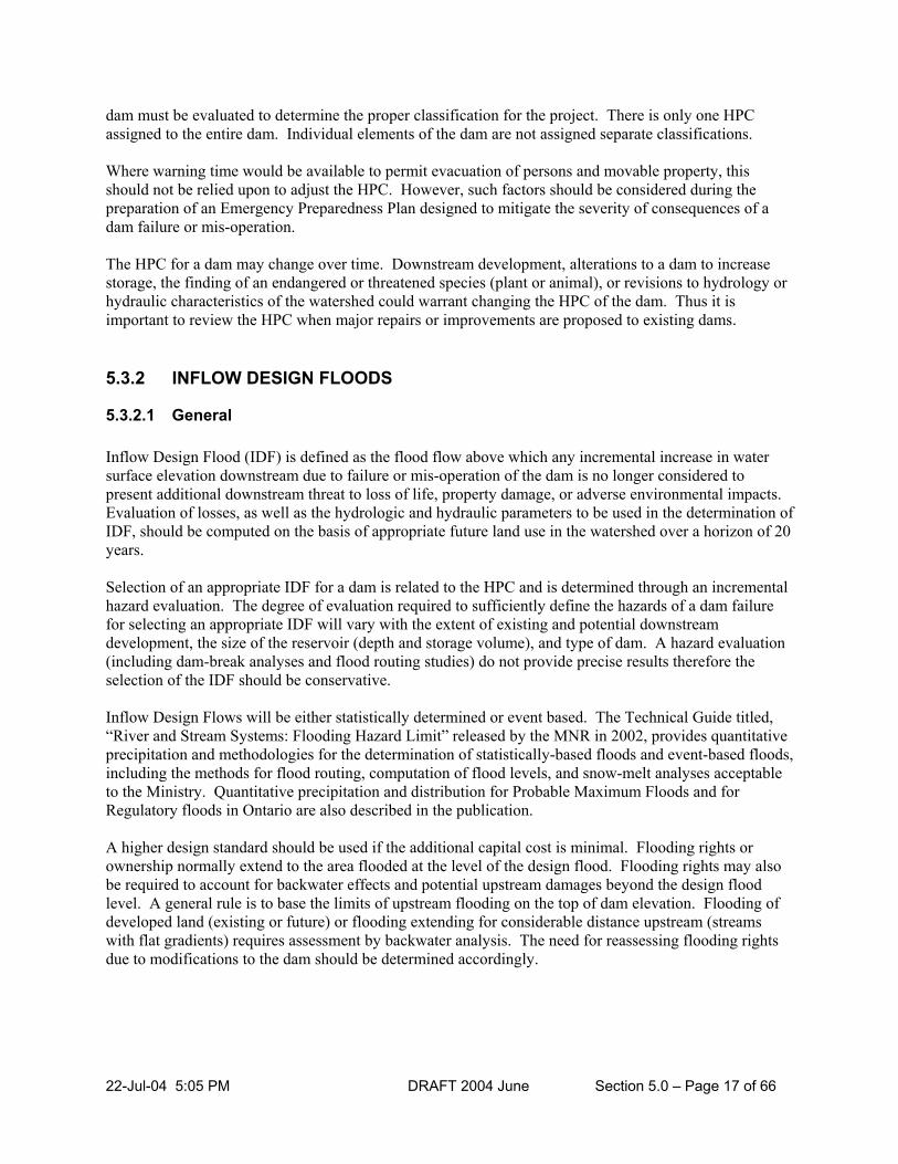
22-Jul-04 5:05 PM DRAFT 2004 June Section 5.0 – Page 17 of 66
dam must be evaluated to determine the proper classification for the project. There is only one HPC assigned to the entire dam. Individual elements of the dam are not assigned separate classifications. Where warning time would be available to permit evacuation of persons and movable property, this should not be relied upon to adjust the HPC. However, such factors should be considered during the preparation of an Emergency Preparedness Plan designed to mitigate the severity of consequences of a dam failure or mis-operation. The HPC for a dam may change over time. Downstream development, alterations to a dam to increase storage, the finding of an endangered or threatened species (plant or animal), or revisions to hydrology or hydraulic characteristics of the watershed could warrant changing the HPC of the dam. Thus it is important to review the HPC when major repairs or improvements are proposed to existing dams. 5.3.2 INFLOW DESIGN FLOODS
5.3.2.1 General Inflow Design Flood (IDF) is defined as the flood flow above which any incremental increase in water surface elevation downstream due to failure or mis-operation of the dam is no longer considered to present additional downstream threat to loss of life, property damage, or adverse environmental impacts. Evaluation of losses, as well as the hydrologic and hydraulic parameters to be used in the determination of IDF, should be computed on the basis of appropriate future land use in the watershed over a horizon of 20 years. Selection of an appropriate IDF for a dam is related to the HPC and is determined through an incremental hazard evaluation. The degree of evaluation required to sufficiently define the hazards of a dam failure for selecting an appropriate IDF will vary with the extent of existing and potential downstream development, the size of the reservoir (depth and storage volume), and type of dam. A hazard evaluation (including dam-break analyses and flood routing studies) do not provide precise results therefore the selection of the IDF should be conservative. Inflow Design Flows will be either statistically determined or event based. The Technical Guide titled, “River and Stream Systems: Flooding Hazard Limit” released by the MNR in 2002, provides quantitative precipitation and methodologies for the determination of statistically-based floods and event-based floods, including the methods for flood routing, computation of flood levels, and snow-melt analyses acceptable to the Ministry. Quantitative precipitation and distribution for Probable Maximum Floods and for Regulatory floods in Ontario are also described in the publication.
A higher design standard should be used if the additional capital cost is minimal. Flooding rights or ownership normally extend to the area flooded at the level of the design flood. Flooding rights may also be required to account for backwater effects and potential upstream damages beyond the design flood level. A general rule is to base the limits of upstream flooding on the top of dam elevation. Flooding of developed land (existing or future) or flooding extending for considerable distance upstream (streams with flat gradients) requires assessment by backwater analysis. The need for reassessing flooding rights due to modifications to the dam should be determined accordingly.

22-Jul-04 5:05 PM DRAFT 2004 June Section 5.0 – Page 18 of 66
5.3.2.2 Inflow Design Flood Criteria The following information is to be used in the application of the inflow design flood criteria shown in Table 5.3 below. 1) The flood magnitudes are minimum criteria for design floods. Where the value of the structure or of
downstream or upstream improvements or development is so high that the cost of exceeding the upstream design flood level and creating flood damages or failure of the owner’s dam could be greater than the additional cost incurred in providing additional discharge and/or flood storage capacity, the owner may wish to use a larger design flood. The owner of a dam will likely be held liable for damages caused by the dam.
2) The height of a dam is the vertical distance from the bottom of the stream bed at the downstream toe
of dam to the highest point along the crest of the dam. For dams located on perched erodible foundations, the depth of erosion of the foundation material resulting from dam failure should be used in place of the downstream toe of the dam
3) Storage capacity is taken as the total storage space in the reservoir that would be released below the
design flood elevation. 4) Where reservoir flood storage capacity is insignificant in attenuating the flood peak, the IDF is then
the same as the spillway design flood (SDF). Note that the IDF includes inflow to the dam from the watershed area upstream of the dam as well as the reservoir area.
Table 5.3: Minimum Inflow Design Flood Criteria for Dams
HAZARD POTENTIAL MINIMUM INFLOW DESIGN FLOODS
Very Low 25-Year Flood to Regional Flood
Low Regional Flood to ½ Probable Maximum Flood
Significant ½ Probable Maximum Flood to Probable Maximum Flood
High Probable Maximum Flood
Notes:
1) For dams, having a significant or high HPC, the IDF must be determined by an incremental analysis unless the top of the IDF range is used.
2) For dams having a very low or low HPC, the IDF should be determined through an incremental analysis. Where an incremental analysis is not considered appropriate, the selection of the IDF may be determined from the range of flows indicated in Table 5.3, subject to Minister’s approval.
3) Where an IDF range of flows are indicated in Table 5.3, the magnitude within the range that most closely relates to the hazard potential of the dam should be selected by interpolation as follows:
a) If the dam height is less than 7.5 metres and/or the reservoir volume is less than 100,000 cubic metres, the IDF should be in the lower end of the range.
b) If the dam height is greater than 15 metres and/or the reservoir volume is greater then 1,000,000 cubic metres, the IDF should be at the top of the range.
4) The criteria shown above are for permanent structures; for temporary structures, lower design floods may be used commensurate with the hazard.
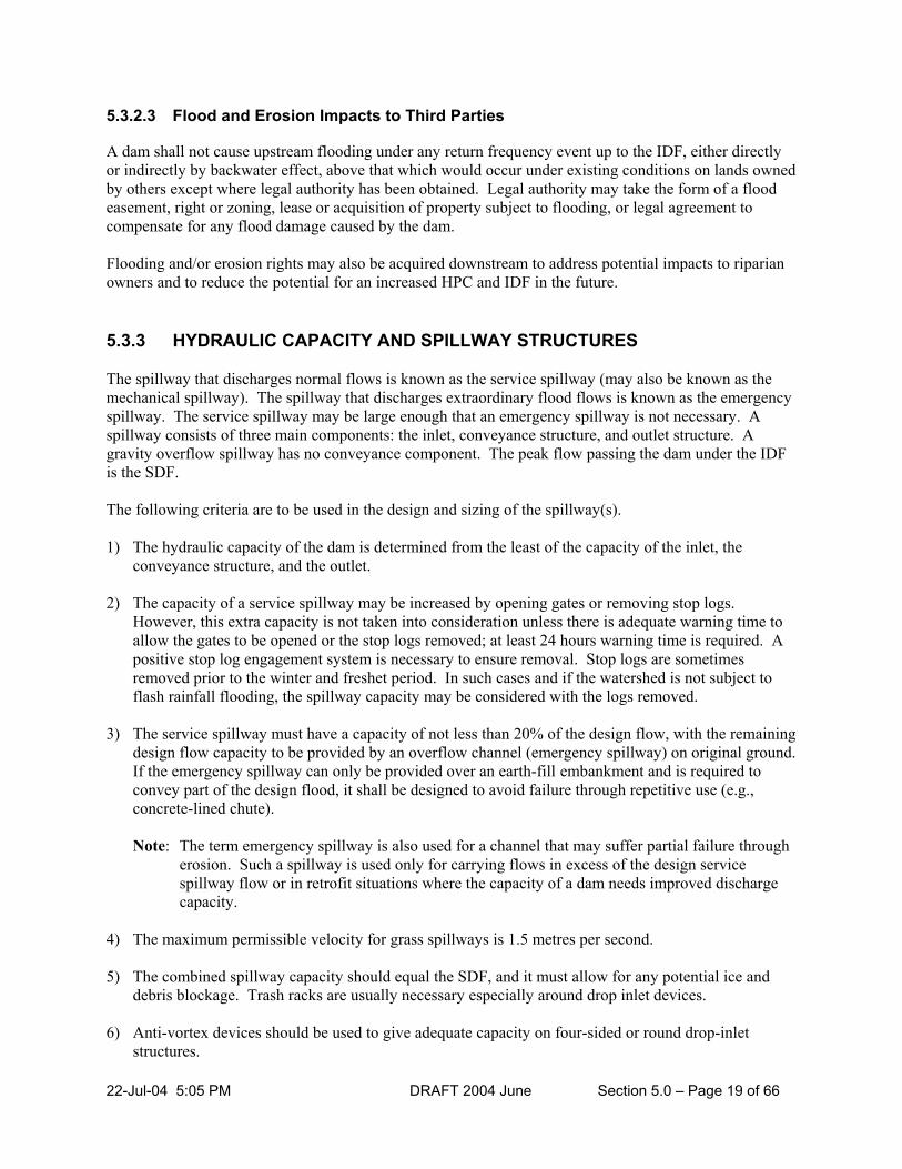
22-Jul-04 5:05 PM DRAFT 2004 June Section 5.0 – Page 19 of 66
5.3.2.3 Flood and Erosion Impacts to Third Parties A dam shall not cause upstream flooding under any return frequency event up to the IDF, either directly or indirectly by backwater effect, above that which would occur under existing conditions on lands owned by others except where legal authority has been obtained. Legal authority may take the form of a flood easement, right or zoning, lease or acquisition of property subject to flooding, or legal agreement to compensate for any flood damage caused by the dam. Flooding and/or erosion rights may also be acquired downstream to address potential impacts to riparian owners and to reduce the potential for an increased HPC and IDF in the future. 5.3.3 HYDRAULIC CAPACITY AND SPILLWAY STRUCTURES The spillway that discharges normal flows is known as the service spillway (may also be known as the mechanical spillway). The spillway that discharges extraordinary flood flows is known as the emergency spillway. The service spillway may be large enough that an emergency spillway is not necessary. A spillway consists of three main components: the inlet, conveyance structure, and outlet structure. A gravity overflow spillway has no conveyance component. The peak flow passing the dam under the IDF is the SDF. The following criteria are to be used in the design and sizing of the spillway(s). 1) The hydraulic capacity of the dam is determined from the least of the capacity of the inlet, the
conveyance structure, and the outlet. 2) The capacity of a service spillway may be increased by opening gates or removing stop logs.
However, this extra capacity is not taken into consideration unless there is adequate warning time to allow the gates to be opened or the stop logs removed; at least 24 hours warning time is required. A positive stop log engagement system is necessary to ensure removal. Stop logs are sometimes removed prior to the winter and freshet period. In such cases and if the watershed is not subject to flash rainfall flooding, the spillway capacity may be considered with the logs removed.
3) The service spillway must have a capacity of not less than 20% of the design flow, with the remaining
design flow capacity to be provided by an overflow channel (emergency spillway) on original ground. If the emergency spillway can only be provided over an earth-fill embankment and is required to convey part of the design flood, it shall be designed to avoid failure through repetitive use (e.g., concrete-lined chute).
Note: The term emergency spillway is also used for a channel that may suffer partial failure through
erosion. Such a spillway is used only for carrying flows in excess of the design service spillway flow or in retrofit situations where the capacity of a dam needs improved discharge capacity.
4) The maximum permissible velocity for grass spillways is 1.5 metres per second.
5) The combined spillway capacity should equal the SDF, and it must allow for any potential ice and
debris blockage. Trash racks are usually necessary especially around drop inlet devices.
6) Anti-vortex devices should be used to give adequate capacity on four-sided or round drop-inlet structures.

22-Jul-04 5:05 PM DRAFT 2004 June Section 5.0 – Page 20 of 66
7) Earth around a drop-inlet structure should be protected from erosion with riprap. 8) The outlet structure must safely discharge water back to the stream and avoid eroding the base of the
dam or the downstream channel. Special energy dissipation structures may be required. At the very least, the outlet structure should extend a sufficient distance beyond the base of the earth embankment to avoid undermining by erosion. The outlet structure may be an extension of the conveyance structure.
9) A low flow outlet must be provided to maintain dry weather flow. A low flow outlet may be separate
or combined with a service spillway. 10) Anti-seepage collars or cut-off walls are required on conveyance structures through dam
embankments. 11) Joints on all spillway structures must be watertight.
12) If the outlet works are controlled by stop logs, they must be designed to be removed under flood
conditions.
5.3.4 FREEBOARD Freeboard provides a margin of safety against overtopping failure of dams. It is generally not necessary to prevent splashing or occasional overtopping of a dam by waves under extreme conditions. However, the number and duration of such occurrences should not threaten the structural integrity of the dam, interference with project operation, or create hazards to personnel. Freeboard provided for concrete dams can be less conservative than for embankment dams because of their resistance to wave damage and erosion. If studies demonstrate that concrete dams can withstand the IDF while overtopping without significant erosion of foundation or abutment material, then no freeboard should be required for the IDF condition. Special consideration may be necessary in cases where a waterpower facility is located near the toe of a dam. Normal freeboard is defined as the difference in elevation between the top of the dam and the normal maximum reservoir elevation. Minimum freeboard is defined as the difference in reservoir elevation between the top of the dam and the maximum reservoir elevation water surface elevation that would result from routing the IDF through the reservoir. Intermediate freeboard is defined as the difference between intermediate storage level and the top of the dam. Intermediate freeboard may be applicable when there is exclusive flood control storage. The following guidelines should be used to determining appropriate freeboard allowances. 1) Freeboard allowances should be based on site-specific conditions and the type of dam (concrete or
embankment). Both normal and minimum freeboard requirements should be evaluated in determining the elevation of the top of dam. The resulting higher top-of-dam elevation should be adopted for design. Freeboard allowances for wind-wave action should be based upon the most reliable wind data available that are applicable to the site. The significant wave should be the minimum used in determining requirements for this component of freeboard.

22-Jul-04 5:05 PM DRAFT 2004 June Section 5.0 – Page 21 of 66
2) Computations of wind-generated wave height, set-up, and run-up should incorporate selection of a reasonable combined occurrence of reservoir level, wind velocity, wind direction, and wind durations based on site-specific studies. It is highly unlikely that maximum wind speeds will occur when the reservoir water surface elevation is at its maximum elevation resulting from routing the IDF, unless the reservoir capacity is small compared to flood volume because the maximum level generally persists only for a relatively short period of time (i.e., a few hours). Consequently, winds selected for computing wave heights should be appropriate for the short period that the reservoir would reside at or near maximum levels. Normal reservoir levels persist for long periods of time. Consequently, maximum winds should be used to compute wave heights.
3) Freeboard allowance for settlement should be applied to account for consolidation of foundation and
embankment materials when uncertainties exist in computational methods or the where data contained unreliable values for camber to be accurately accounted for in the design. Freeboard allowance for settlement should not be applied where accurate determination of settlement can be made and is included in the camber. Freeboard allowance for embankment dams for estimated earthquake-generated movement, resulting seiches, and permanent embankment displacement or deformations should be considered if a dam is located in an area with potential for intense seismic activity. Reduction of freeboard allowance on embankment dams may be appropriate for small fetches, obstructions that impede wave generation, special slope and crest protection, and other factors.
4) Freeboard for wave and volume displacement due to potential landslides which cannot be
economically removed or stabilized should be considered if a reservoir is located in a topographic setting where the wave or higher water resulting from displacement may be destructive to the dam or may cause serious downstream damage.
5) Total freeboard allowances should include only those components of freeboard which can reasonably
occur simultaneously for a particular reservoir water surface elevation. Components of freeboard and the combination of those components which have a reasonable probability of simultaneous occurrence are listed in the following paragraphs for estimating minimum, normal, and intermediate freeboards. The top of the dam should be established to accommodate the most critical of water surface elevation and freeboard components from the following combinations.
f) Freeboard on earth embankments may also be used to protect the core from the action of direct
contact with surface water and from development of frost lenses and cracks caused by drying.
g) Additional freeboard is often necessary, especially if there is a question about spillway adequacy due to debris blockage.
For minimum freeboard combinations, the following components, when they can reasonably occur simultaneously, should be added to determine the total minimum freeboard requirement: 1) Wind-generated wave run-up and set-up for a high wind event appropriate for the maximum
reservoir stage for the IDF; 2) Effects of possible malfunction of the spillway and/or outlet works during routing of the IDF; 3) Settlement of embankment and foundation not included in the crest camber; and

22-Jul-04 5:05 PM DRAFT 2004 June Section 5.0 – Page 22 of 66
4) Landslide-generated waves and/or displacement of reservoir volume should only be considered where landslides are triggered by the occurrence of higher water elevations and intense precipitation associated with the occurrence of the IDF.
The following Table 5.4 provides minimum freeboard allowances for small dams based on potential wave action.
Table 5.4: Minimum Freeboard for Small Dams
Reservoir Fetch (Length) Freeboard
Under 200 m 300 mm
Up to 400 m 450 mm
Up to 800 m 600 mm
Over 800 m Individual analysis required
For normal freeboard combinations, the more critical of the following two combinations of components should be used for determining normal freeboard requirements. 1) Wind-generated wave run-up and set-up for maximum wind and settlement of embankment and
foundation not included in camber. 2) Landslide-generated waves and/or displacement of reservoir volume, settlement of embankment and
foundation not included in camber, and settlement of embankment and foundation or seiches as a result of the occurrence of the maximum credible earthquake (MCE).
For intermediate freeboard combinations, in special cases, a combination of intermediate winds and water surface elevation between normal and maximum levels should be evaluated to determine whether this condition is critical. This may apply where there are exclusive flood control storage allocations. 5.3.5 STRUCTURAL DESIGN AND FACTORS OF SAFETY This section applies to gravity-type structures that resist a head of water on the upstream side. A gravity spillway incorporates wing walls and aprons and may include a downstream stilling basin. Basic Structural Design Requirements and Factors of Safety include the following: 1) Factors of Safety for a gravity section (at middle third) must be at least 2.0 for overturning and 1.75
for sliding under normal operating conditions. These factors may be reduced to 1.5 and 1.25 respectively under flood conditions, and the following loading conditions must be considered:
a) Uplift pressures vary linearly from full headwater to tailwater level. Structures founded on
competent bedrock with little jointing may reduce the total uplift pressures by up to one-third. Uplift pressures may also be reduced if the dam has special drainage and/or monitoring (instrumentation) systems.

22-Jul-04 5:05 PM DRAFT 2004 June Section 5.0 – Page 23 of 66
b) Specific density for silt behind a dam should be taken as 1.4 for horizontal loading, 1.9 for vertical loading.
c) Ice loading depends on climatic conditions and constraining factors. Ice loading should be
applied 0.3 m below the normal water surface. In Ontario, the maximum ice loading normally considered is 75.0 kN/m (5000 pound-force per foot). For major dams in Ontario, consideration should be given to ice loading as high as 146kN/m. Ice loading on timber stop logs is taken as 29.0 kN/m (2000 pound-force per foot).
2) If post-tensioned rock anchorage is used to increase resistance to sliding and overturning, the design
must be based on the soundness of the rock established by field investigation. The specifications for the work must include on-site pull out testing and all relevant installation and material specification details.
3) Expansion joints must be watertight and be provided in concrete gravity dams every 6.0 metres or as
required by the design. 5.3.6 EARTH EMBANKMENTS
Earth embankment dams constitute the majority of structures in Ontario and in other parts of North America and the world. The majority of dam failures are also associated with embankment dams due to overtopping, foundation problems, piping, and seepage. It is therefore important to give serious consideration to geotechnical aspects of these dams and their foundations during the design, construction, operation, and maintenance.
Earth embankment design requires the input of specialized geotechnical engineers. The design depends on:
1) the foundation conditions, 2) the available soils for construction, and 3) the head of water to be retained.
Homogeneous embankments are constructed of impervious soils. Such embankments may require special drainage and filter measures to avoid excessive wetting and sloughing of the downstream face and to control seepage erosion through the dam (piping). Such measures include toe drains and drainage blankets. Drainage blankets are layers of pervious soil extending horizontally from the toe of the dam into the downstream area. Zoned embankments consist of an impervious central core surrounded by shells of pervious, well-draining soils. An upstream layer of impervious material on the front face is sometimes used as an alternative to a central core. Impervious soil materials can be replaced by synthetic materials, such as, plastic membranes, bentonite clay blankets, sheet piles, or concrete.
1) Design Principles
a) The embankment must be designed to avoid excessive stresses on the foundation.
b) Sufficient hydraulic capacity and freeboard must be provided to make the embankment safe
against overtopping from flood flows and wave action.

22-Jul-04 5:05 PM DRAFT 2004 June Section 5.0 – Page 24 of 66
c) Seepage flow must be controlled through the embankment, including its foundation and abutments. Uncontrolled seepage will lead to internal erosion known as piping and sloughing of the downstream face.
d) The upstream slope must be protected against erosion by wave action using riprap or similar
materials. Grass protection may be satisfactory on low hazard structures with small reservoirs. e) The downstream slope must be protected against erosion from rain and any seepage. The portion
of slopes that are normally dry and not otherwise protected from erosion should be sodded or seeded in such a way that a solid cover of sod will be established
f) The embankments should be protected from burrowing animals using typically 60 mm wire mesh,
placed 1.5 m above and below waterline at a depth of 15 cm below the surface.
g) Trees & shrubs whose root systems may promote piping failure are not to be planted onto fill embankments.
h) Earth-fill embankments shall:
i) be constructed with side slopes that will remain stable under saturated conditions ii) have an impervious core consisting of one or more of
(a) clay or other cohesive soil capable of being compacted into an impervious mass; method
of compaction must be such that a standarProctor density of not less than 95% is achieved
(b) a plastic sheet so placed that it remains whole and undamaged during placement of fill
(c) steel sheet piling
(d) wakefield piling (e) concrete (f) grout curtain; or
iii) consist of homogeneous construction material using well-graded granular soil compacted in
layers and with not less than 15 percent of the material passing a 200 sieve screen. Maximum grain size of granular soil is limited only by capability of the compaction equipment used to produce a dense fill with a Standard Proctor density of not less than 95%.
iv) Upstream and downstream slopes must be protected from sloughing by placement of a free-
draining granular layer; upstream protection must extend through the drawdown range; downstream protection must extend from the toe upward to an elevation (H/3 + 0.75 m) above the tailwater where H is the difference in elevation, in metres, between headwater and tailwater. Riprap must be placed as required to protect against erosion.
2) Typical Design for Small Earth Dam
a) top width 3.0 m (usually considered minimum)

22-Jul-04 5:05 PM DRAFT 2004 June Section 5.0 – Page 25 of 66
b) upstream slope 3:1, downstream slope 2:1 (flatter for unstable soils and weak foundations) c) the embankment compacted to not less than 95% Standard Proctor density in 150 mm to 200 mm
layers d) the embankment height increased 300 mm for a freeboard allowance and a further 300 mm for
settlement allowance (camber) e) impervious clay core - top width 1.5 m, 1.5:1 side slopes, 10-6 cm/s permeability
5.3.7 SOILS AND FOUNDATIONS Test pits or borings are required every 15.0 m to 20.0 m, with depth at least 1.5 times the height of the dam. Test pits or borings are required in the reservoir area, one per ha, and for the borrow area. Soil should be classified by the Unified Classification System. Testing is required for strength, natural moisture content, grain size distribution, standard proctor density, and permeability. The foundation, including the abutments (i.e., banks on the side of the dam), should be sufficiently strong to support the structure. Pervious foundations need special measures for seepage control, such as, impervious cut-off trenches and/or drainage and filter devices. Alternatives to cut-off trenches include sheet piling. Grout curtains are used to seal fissures in rock foundations. Seepage from the reservoir may also need controlling. If a clay cut-off trench is used, it should be dug a minimum of 300 mm into the impervious soil. The trench must be a minimum of 1.0 m at the bottom with side slopes no steeper than 1 horizontal to 1 vertical. The material should have a coefficient of permeability less than 10-6 cm/s.
Dams should be founded on undisturbed soil or rock. Soils for use in dam embankments are summarized in Table 5.5.
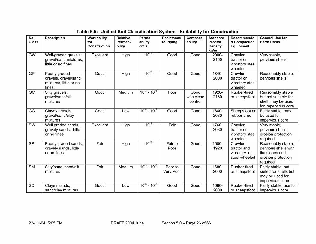
22-Jul-04 5:05 PM DRAFT 2004 June Section 5.0 – Page 26 of 66
Table 5.5: Unified Soil Classification System - Suitability for Construction Soil Class
Description Workability for Construction
Relative Permea- bility
Perme- ability cm/s
Resistance to Piping
Compact- ability
Standard Proctor Density kg/m
Recommended Compaction Equipment
General Use for Earth Dams
GW Well-graded gravels, gravel/sand mixtures, little or no fines
Excellent High 10-2 Good Good 2000-2160
Crawler tractor or vibratory steel wheeled
Very stable, pervious shells
GP Poorly graded gravels, gravel/sand mixtures, little or no fines
Good High 10-2 Good Good 1840-2000
Crawler tractor or vibratory steel wheeled
Reasonably stable, pervious shells
GM Silty gravels, gravel/sand/silt mixtures
Good Medium 10-3 - 10-6 Poor Good with close
control
1920-2160
Rubber-tired or sheepsfoot
Reasonably stable but not suitable for shell; may be used for impervious core
GC Clayey gravels, gravel/sand/clay mixtures
Good Low 10-6 - 10-8 Good Good 1840-2080
Sheepsfoot or rubber-tired
Fairly stable; may be used for impervious core
SW Well graded sands, gravely sands, little or no fines
Excellent High 10-3 Fair Good 1760-2080
Crawler tractor or vibratory steel wheeled
Very stable, pervious shells; erosion protection required
SP Poorly graded sands, gravely sands, little or no fines
Fair High 10-3 Fair to Poor
Good 1600-1920
Crawler tractor and vibratory or steel wheeled
Reasonably stable; pervious shells with flat slopes and erosion protection required
SM Silty/sand, sand/silt mixtures
Fair Medium 10-3 - 10-6 Poor to Very Poor
Good 1680-2000
Rubber-tired or sheepsfoot
Fairly stable; not suited for shells but may be used for impervious cores
SC Clayey sands, sand/clay mixtures
Good Low 10-6 - 10-8 Good Good 1680-2000
Rubber-tired or sheepsfoot
Fairly stable; use for impervious core

22-Jul-04 5:05 PM DRAFT 2004 June Section 5.0 – Page 27 of 66
Soil Class
Description Workability for Construction
Relative Permea- bility
Perme- ability cm/s
Resistance to Piping
Compact- ability
Standard Proctor Density kg/m
Recommended Compaction Equipment
General Use for Earth Dams
ML Inorganic silts and very fine sands, silty or clayey fine sands, silty clays
Fair Medium 10-3 - 10-6 Poor to Very poor
Good to Poor Close Control Essential
1540-1920
Sheepsfoot Poor stability; may be used for embankments with close control of construction.
CL Inorganic clays of low to medium plasticity, gravely sand, silty clays
Good to Fair Low 10-6 - 10-8 Good to Fair
Fair to Good
1540-1920
Sheepsfoot Stable, impervious core
OL Organic silts and silty clays of low plasticity
Fair Medium to Low
10-4 - 10-6 Good to Poor
Fair to Poor
1280-1600
Sheepsfoot Not Suitable
MH Inorganic silts, elastic silts
Poor Medium to Low
10-4 - 10-6 Good to Poor
Poor to Very Poor
1120-1540
Sheepsfoot Not Suitable
CH Inorganic clays of high plasticity
Poor Low 10-6 - 10-8 Excellent Fair to Poor
1200-1680
Sheepsfoot Fair stability with flat slopes, impervious cores
OH Organic clays and silts with medium to high plasticity
Poor Low 10-6 - 10-8 Good to poor
Poor to Very Poor
1040-1600
Sheepsfoot Not Suitable
Pt Peat and other highly Organic soils
Not suitable for construction

22-Jul-04 5:05 PM DRAFT 2004 June Section 5.0 – Page 28 of 66
5.3.8 TEMPORARY WORKS
Temporary works should be designed to provide for their intended purpose taking into account the risks of failure involved. Delays in the construction schedule must be taken into consideration in the design requirements. They must be installed and removed promptly as intended. Temporary works (such as cofferdams):
1) may be designed using lower design floods than those identified in Table 5.3, Inflow Design Floods. 2) required for one season can be designed based on an appropriate seasonal design storm. 3) should be located taking into consideration the impact on aquatic resources and riparian rights. 4) should have an outlet capable of passing the base flows in the watercourse during the construction
period. 5) should contain a description of the installation and removal sequence.
Conditions regarding the time of the year for installation and removal of temporary works must be included in the approval. Sedimentation prevention is an important concern with any temporary works. See Section 5.8.
5.3.9 ENVIRONMENTAL CONSIDERATIONS The dam and reservoir often have impact on valuable natural resources, such as, fish and wildlife habitat, timber, mineral, oil and gas, etc. The dam and reservoir may also impact on valuable historical and archeological sites. Potential impact on fish habitat and other aquatic resources are discussed in Section 4.6.
1) The ecology of a reservoir will be different from the previously-existing stream. This will lead to
different habitat and fish species. A dam and reservoir will require an authorization under the Federal Fisheries Act and a compensation agreement will be required.
2) Bottom draw-off outlets should be considered for all dams over 3 metres in height. Such outlets
should be placed at least three metres below the water surface so that there will be no increase in downstream temperature.
3) A dam that blocks fish migration should be equipped with a fishway. Both safe ascent and descent of
fish passage should be provided. 4) Dams should not generally be constructed to interfere with marshes, swamps, fens, or significant
wildlife habitat. 5) The reservoir area behind a dam should not interfere with wells, septic sites, or waste disposal areas.
Seepage water from the reservoir should not cause wetting of land owned by others. 6) The design of the dam discharge facilities and operating plan for the reservoir should minimize the
impact of trapping suspended sediments.

22-Jul-04 5:05 PM DRAFT 2004 June Section 5.0 – Page 29 of 66
7) Water quality in the reservoir and downstream should be assessed, including water temperature, dissolved oxygen, plant nutrients, and turbidity.
8) Provision should be made in the design and operation of a dam to maintain adequate downstream
flows at all times. These provisions must be described in the operating manual. Generally, at least two-thirds of normal stream flow should be maintained at all times.
9) The outlet works must be provided with a low flow outlet which shall be of sufficient size to pass the
base flow in the stream during the summer months. Base flow is that portion of the stream flow which originates from groundwater storage. The requirement for downstream minimum flow may be increased based on ecological and riparian concerns.
10) Large evaporation losses may require drawdown of the reservoir to maintain downstream base flow.
A dam with a large surface area should not be located on a small stream on which flows have to be maintained. Evaporation losses for summer days can be estimated as 68 litres per minute per hectare of reservoir area.
5.3.10 DAM REMOVAL AND DECOMMISSIONING 5.3.10.1 General
A large number of dams in Ontario were constructed during the early part of the last century. They were built for specific purposes, such as, timber transport, provision of motive power for sawmills and gristmills, water supply for livestock and agriculture, etc. With the advent of electricity and shift of population from rural to urban Ontario, many of these structures are no longer required for the purpose for which they were originally built. Dams which do not serve a useful purpose and pose a hazard to life and property should be considered for decommissioning. Planning and implementation of decommissioning of dams should take into account all relevant physical, social, economic, and environmental factors. Before decommissioning takes place, the dam owner should prepare appropriate decommissioning plans. A full hydraulic and ecological impact assessment is normally required to support a dam removal. The objective is to restore the site as close as possible to its original condition prior to the construction of the dam. However, it is acknowledged that site conditions, in most situations, would have been permanently altered due to the presence of the dam over an extended period. Nevertheless, every effort should be made to restore the site in an environmentally responsible manner. Other impacts of decommissioning or removal of the dam may include downstream deposition of material eroded from the reservoir area. Natural channel design techniques and a sediment transport evaluation should be applied to minimize disruption to downstream features.
A dam should be considered as decommissioned or removed only when all the requirements of the decommissioning plan are met. Prior to decommissioning, the owner should be required to prepare a detailed plan for withdrawal of the dam from service, indicating measures necessary for site safety, especially with regard to public safety and flood discharge capability of spill structures. The possibility of exposure of any remaining structures to loads or combinations of loads not foreseen in the original design or to otherwise unacceptable conditions should be checked in detail. If the decommissioned dam has not been totally removed, it may

22-Jul-04 5:05 PM DRAFT 2004 June Section 5.0 – Page 30 of 66
still require regular surveillance. The need for ongoing surveillance and maintenance should be determined prior to decommissioning. The possible consequences of the decommissioning on downstream development, including the operation and safety of downstream dams and reservoirs, should be examined with special attention to emergency-related aspects and the possible ongoing need for an Emergency Preparedness Plan if significant portions of the dam remain. A dam has an influence on the production of ice in a river. Sheet ice will be produced in the reservoir, leading to possible ice jamming below the dam. However, in many situations ice stays in place and melts in the reservoir. Also, ice breaks up falling over a dam. A dam may be used to reduce the hydraulic gradient of a river reach by creating a backwater and promoting ice sheet formation, thus eliminating an open water frazil ice producing section of fast water. This is seen as a positive result in reducing downstream ice jamming due to frazil ice production. It is critical that the designer determines the physical characteristics of the sediment that have accumulated in the reservoir upstream of the dam that is proposed for decommissioning. These characteristics would include grain size, depth of material, and volume. Removal of the dam structure may lead to erosion of some of the material in the reservoir, and the material may settle out in the channel downstream. Natural channel design techniques and sediment transport evaluation should be applied to ensure that: 1) a stable natural stream system develops in the long term both downstream, in the reservoir area, and
upstream; and 2) the dam removal causes minimum environmental damage in the short term.
Demolition of the dam or removal of any of its structural components or equipment should generally not be started before the reservoir has been emptied. In special cases where this is not possible, demolition must not constitute a safety hazard. Structures that remain after decommissioning shall be physically and chemically stable and should not impose an unacceptable risk to public health and safety or to the environment. The stability of remaining structures should be examined taking into account the possible effects and consequences of scouring, erosion, and/or deterioration of the foundation. The consequences of any chemical instability and leaching of chemicals into the environment should not endanger public health, safety, or the environment. Chemical stability of the dam must be considered in relation to its ability to maintain the integrity of its constituent parts. 5.3.11 FISHWAYS
5.3.11.1 General Fishways are structures that allow fish to move upstream past obstructions in the river and can include structures and devices to allow fish to move safely downstream. Fishways for upstream movement are usually flume-type structures incorporating a series of baffles and by-pass channels. Most common types of flumes are pool and weir, denil, and vertical slot. Flumes with pools and weirs are only suitable for salmonoid species and are only effective over a small range of flows. The design flow for fish passage should not exceed a frequency of a 1:10 year 3 day delay. This is the flow that is exceeded on average every ten years for three consecutive days.

22-Jul-04 5:05 PM DRAFT 2004 June Section 5.0 – Page 31 of 66
Fishways generally increase the cost of a dam substantially and, in most cases, have a much lower efficiency than a natural stream. Some species may not be able to use certain types of fishways. Fishways are poor substitutes for natural systems and a dam requiring a fishway should only be considered where there is no other alternative. 5.3.11.2 Criteria for Assessment of Fishways in Dams 1) Fishways shall be of a design satisfactory to the Ministry and DFO. 2) Fishways shall be designed such that they will allow free passage of all anadromous species of fish
resident or that may be reasonably expected to be resident in the stream and shall meet the following general criteria.
a) The lower end of the fishway should be located where the majority of fish will be attracted and
can access the fishway. b) The fishway must remain operable over the range of headwater and tailwater levels that are
anticipated during the migration periods. c) Pool size and gradient in the fishway must be designed for adequate fish-holding capacity and
energy dissipation.
3) The local MNR District Area office and DFO shall be contacted for information on target fish species and specific fish design requirements.
5.3.11.3 Criteria for Assessment of Downstream Passage at Dams Safe downstream passage of fish species at dams is site specific in all cases and usually includes a combination of physical, chemical, or biologic conditions to be met. The local MNR District Area office and DFO shall be contacted for information on target fish species and specific fish design requirements. 5.4 CRITERIA AND STANDARDS FOR THE PREPARATION OF
OPERATIONS, MAINTENANCE, SURVEILLANCE, AND EMERGENCY PREPAREDNESS PLANS FOR DAMS
5.4.1 GENERAL One of the purposes of the LRIA, as defined in section 2(f), is the protection of persons and of property by ensuring that dams are suitably operated and maintained. Plans and Specifications approval must include a condition which requires the dam owner to comply with the provisions contained in the Dam Operations, Maintenance, and Surveillance Plans for their dams. An Operations Plan details the manner in which the dam will be operated under expected and possible adverse operating conditions to protect life, property, and the environment and to deliver the expected benefits from the dam. The scope of an Operations Plan depends on the complexity of the structure, including factors, such as, dam size, type of appurtenances, and other facilities, such as, waterpower, fishways, saddle dams, municipal and private potable intakes, and other water users.
The operation of a dam involves adjustment of downstream flows and reservoir water levels, controlling debris and ice, opening and closing of discharge facilities, and most importantly, ensuring public safety. Most dams in Ontario do not require full-time operators; however, specified operating procedures must be

22-Jul-04 5:05 PM DRAFT 2004 June Section 5.0 – Page 32 of 66
followed on a regular basis to adhere to all constraints contained in the dam operation plan especially leading up to and during emergency situations. A good Maintenance Plan will protect a dam against deterioration and prolong its life. Virtually all components of a dam including materials and equipment used in its construction and operation are susceptible to deterioration and will require maintenance. Furthermore, the cost of a proper maintenance program is relatively small compared to the cost of repairs, dam failure, or mis-operation. A maintenance program should consist of three basic components: namely, emergency or immediate maintenance, major or required maintenance, and minor or routine maintenance. Instructions for performing maintenance should be described in detail, in writing, so that new personnel can understand the tasks that can then be verified after they have been completed. All needed maintenance work should be identified and listed in the above three categories. An effective Surveillance (inspection and monitoring) Plan is essential for early identification of problems providing timely maintenance of a dam. Inspections performed on a regular basis are one of the most economical means of monitoring to ensure the safety and longevity of a dam. Instruments designed for monitoring potential deficiencies at existing dams must take into account the threat to loss of life, property damage, and environmental impacts that the dam failure presents. Therefore, the extent of instrumentation needed for a facility depends on the complexity of the structure, size of the reservoir, modes of failure, or mis-operation as well as the hazard to upstream and downstream persons, property, and the environment. The instrumentation program should involve instruments and evaluation methods that are appropriate for the facilities, and the requirements should be identified in a Monitoring Plan which shall be specific for the dam. For less complex dam sites, the Operation, Maintenance, and Surveillance (inspection and monitoring) Plans can be documented in a single OMS Manual. The OMS Manual contains information on the dam operation and maintenance as well as inspection, monitoring, and instrumentation for the dam. For dams in the very low HPC, this document will vary from being very brief to just a check list of actions. 5.4.2 OPERATIONS PLAN 5.4.2.1 Contents of the Operations Plan The Operations Plan should provide complete, clear, and step-by-step instructions for operating all mechanical and electrical mechanisms associated with the dam, including outlet control works and spillway gates. Proper sequence should be emphasized and the correct method of opening and closing of the discharge facilities during high and low flows should be stipulated. Operating concerns/constraints peculiar to a specific structure should be listed. For hydraulic and electric gates, a schematic diagram should be provided showing each component, including any back-up equipment and its place in the operating sequence. This may include off-site equipment for automatically or manually controlled dams. Instructions on routine and general operation of the reservoir, including the management of inflows, water levels and outflows, should be given. These instructions should state the maximum water level to be permitted at different times of the year, maximum and minimum permissible storage in the reservoir, maximum and minimum permissible outflows, and other operating instructions. The plan should also

22-Jul-04 5:05 PM DRAFT 2004 June Section 5.0 – Page 33 of 66
describe the constraints that may exist upstream and downstream that may limit or prevent excessive ramping rates, spillway releases, or taking water into storage. The Operations Plan sets out the operating limits for the facility and the rule curve for the operation of the structure. The plan will also set out the sequence for the operation of the discharge facilities, depending on the level of the reservoir and upstream and downstream conditions. In addition, other requirements, such as, maintenance of minimum flows, maintenance of water levels within specified limits during certain times of the year, and operation of the structure during emergency situations, etc., will also be defined in the Operations Plan. Please refer to Section 4.5.1 for details on conditions of approval. 5.4.2.2 Personnel The required duties and qualifications of operators in regard to the safe operation of the dam should be defined listing the appropriate areas of involvement. The description may include details of suitable training programs. 5.4.2.3 Records Conditions of approval should require the dam owner to maintain permanent tables and/or spreadsheets containing operational information and records appropriate to the type of dam. A table is a record of pertinent data on the operation of the dam. Permanent records should be maintained as an ongoing history available for general use and reference. The records should be appropriate for transfer to the appropriate regulatory agency or new owner upon transfer of ownership or control of the facility. If the security of the permanent records cannot be guaranteed on site, the records should be duplicated off site. Where appropriate, the following items should be recorded:
1) weather conditions; 2) changes to normal operation; 3) unusual events, conditions, or public activity; 4) unusual maintenance activities; 5) alarms or annunciations; 6) inspection activity; 7) date and time of altered dam settings 8) water levels, stop log settings, gate openings, flow information, etc; and 9) operational test of flow control equipment. The following items should also be covered or referenced in a permanent record file: 1) instructions given by regulatory agencies, dam designer or other authority, and the record of
compliance and details of any remedial action;

22-Jul-04 5:05 PM DRAFT 2004 June Section 5.0 – Page 34 of 66
2) as-built drawings from original construction and all subsequent construction phases; 3) readings on any instrumentation; 4) all design data including both original and modifications or revisions; 5) all inspections and Dam Safety Reviews; 6) chronological history of the structure; 7) photographic record; and 8) stage-discharge-storage curves and operating rule curves.
Suitable instructions should be in place for the recording of this operating information, including references to drawings and technical operation and maintenance manuals. 5.4.2.4 Operating Instructions Operating Instructions in the Operations Plan should include: 1) guidelines and procedures for the initial operation of a new dam and requirements relating to factors,
such as, impounding procedures, maximum allowable flows, reservoir levels, drawdown procedures in case of emergency, and other emergency procedures. The operation of a dam shall not violate any important design assumptions that could impair the safety of the dam;
2) details of spillway operating parameters, rating curves, power requirements, and restrictions; 3) a pre-determined set of operating rules and objectives for all discharge facilities to be operated at all
times. The development of such rules shall consider the safe passage of all hydrological events, including the IDF.
4) Rule curves for operation during the flood season such that all floods, including the IDF, can be
passed safely. Rules for flood operations are normally based on reservoir level, rate of level rise, snow pack, rainfall, time of year, and (to some extent) weather forecasts. Such operating rules should be documented in the Operations Plan.
5.4.2.5 Flood Operating Procedures The Operations Plan should define accurately the procedures to ensure that the reservoir will be operated in such a manner that inflows can be routed safely. Drawdown or other reservoir operating restrictions should be documented. Descriptions of all the various parts of the dam that affect the above requirements should be provided and, where appropriate, manufacturer’s operating manuals should be referenced and readily available. Concise operating instructions should be provided for use during normal operation as well as in the case of extreme floods by qualified dam operators who are not necessarily familiar with the particular dam.

22-Jul-04 5:05 PM DRAFT 2004 June Section 5.0 – Page 35 of 66
Details of normal operating conditions should be provided to indicate such items as: inflows and discharges, normal levels, storage volumes, spillway and tailwater rating curves, spillway operating parameters, power supplies, and environmental restrictions. Potential emergency conditions should be identified and listed with related recommended operating parameters and restraints. The instructions should detail the flow capacities of the structures and related water elevations, list the hazard areas and flows at which they are affected, and provide details about warning systems as well as primary and backup power systems. 5.4.2.6 Emergency Operating Procedures General procedures and considerations should be outlined, such as, any special instructions for spillway operation and instructions on reservoir drawdown to alleviate the effects of emergencies. These should include any limitations on reservoir surcharge or drawdown, implications of rising flows downstream, list of erosion-prone areas of river banks, and reservoir slopes that should be monitored. Operations just prior to and during an emergency would follow procedures contained in the Emergency Preparedness Plan. Operation for emergency drawdown of the reservoir in the event of damage to the dam, including precautions to avoid damage to facilities and any restrictions on the rate of drawdown, should be provided. Procedures for reservoir control and discharge in the case of a developing breach or potential breach and for any emergency drawdown of the reservoir should also be established and specified in the Operations Plan. 5.4.2.7 Ice and Debris Handling Where contributing watershed areas or reservoirs contain significant quantities of ice or debris, procedures shall be established for safe handling of ice and/or debris. The details, functions, and required operating activities of log, trash, and ice booms, including trash removal and any ice-growth restrictions on structures or gates, should be described in the Operations Plan. The operation of any required bubbler systems or other devices for ice prevention should be described. 5.4.2.8 Flood Forecasting The Operations Plan should identify the methods and/or sources of flow/flood forecasting with a list of other available sources of flood forecast information. In Ontario, agencies that maintain information which may be relevant for flood forecasting include Provincial Ministries, Conservation Authorities, Ontario Power Generation, other upstream dam owners, Ottawa River Regulation Planning Board, Lake of the Woods Control Board, Trent-Severn Waterway, etc. References of the relevant agencies and the names of the contacts should be included in the Plan.
5.4.2.9 Water Balance for Tailings Basins For tailings basins, the Operations Plan should contain the requirement to review the water balance on a periodic basis, at least annually, to ensure safe operation during flood or drought conditions. The gains to and losses from a tailings basin can vary on a daily, monthly, and yearly basis. These variations should be taken into account as they may differ from average conditions. At a minimum, the water balance study should take into account:

22-Jul-04 5:05 PM DRAFT 2004 June Section 5.0 – Page 36 of 66
1) direct precipitation; 2) tailings transport water; 3) mine water; and 4) contributing watershed inflows and reservoir losses including evaporation, water retained in tailings,
seepage, and recirculation to the mill or other industrial processes. 5.4.2.10 Schedule of Routine Tasks The Operations Plan should contain a schedule that includes routine tasks as well as less frequent tasks. Such a schedule serves to formalize the requirements and facilitate the operator to perform their duties.
5.4.3 MAINTENANCE PLAN 5.4.3.1 Contents of the Maintenance Plan A typical Maintenance Plan would consist of the following components:
1) maintenance policies and procedures; 2) responsibilities for maintenance of dam and appurtenant structures; 3) responsibilities for maintenance of equipment including instrumentation (including off-site equipment
for remotely operated dams); and 4) record keeping, storage, and retrieval. 5.4.3.2 Maintenance Priorities The relative priorities of maintenance should be as follows: 1) Emergency maintenance (immediate); 2) Major maintenance (required); and 3) Minor maintenance (routine or continuing). 5.4.3.3 Emergency Maintenance (Immediate Maintenance) There are some maintenance requirements which are brought about due to conditions which are critical and call for immediate attention. For example, a spillway can be blocked by debris or ice and rendered partly or fully inoperable. If the normal discharge is restricted, overtopping of the dam can occur resulting in disastrous consequences. In other situations, a dam may be showing signs of piping or internal erosion which is usually indicated by increasingly cloudy seepage. Evidence of excessive seepage appearing anywhere at the dam site should be taken seriously. Progressive erosion and slope failures can occur on the upstream or downstream face of the dam due to seepage through the embankment or after heavy rainfall.

22-Jul-04 5:05 PM DRAFT 2004 June Section 5.0 – Page 37 of 66
Although remedy for critical problems may be obvious, most of the immediate maintenance programs require services of a professional engineer familiar with the construction and maintenance of dams and such action should be activated when any of the immediate maintenance problems are encountered. 5.4.3.4 Major Maintenance (Required Maintenance) Required maintenance items are less critical than those of immediate maintenance; nevertheless, they should be completed as soon as possible after defective conditions are noted. The following are some examples of required maintenance: 1) All underbrush and trees should be removed from the dam, and a good grass cover should be
maintained; 2) Eroded areas and gullies on embankment dams should be restored and reseeded; 3) Defective spillway gates, valves, and other appurtenant features of a dam should be repaired; and 4) Deteriorated concrete should be repaired as soon as weather permits.
Table 5.6: Minimum Suggested Frequency for Surveillance Inspection
Item High
Hazard Potential (c)
Significant
Hazard Potential (c)
Low Hazard Potential c)
Routine Visual Inspection(a) Monthly Semi-annually Annually
Scheduled Inspection (b) Annually Every 5 years Every 5 years
Special Inspection (d) As required As required As required
Instrumentation As per
Surveillance Plan
As per
Surveillance Plan
As per
Surveillance Plan
Test Operation of Outlet Gates and Mechanical Components
Annually Annually Annually
Note:
All dams with High Hazard Potential may be inspected more frequently than the minimum suggested schedule outlined above.
1) Frequency of the Routine Visual Inspections may be selected to suit seasonal restraints and dam and site conditions. Note: Seepage readings (or any other conditions subject to change) should be measured at this time.
2) Scheduled Inspections are intended as more thorough inspections performed by the appropriate representatives of the owner responsible for safety surveillance.
3) See Table 5.1 for Selection Criteria for HPC for dams.
4) Special Inspections should be conducted after floods, earthquakes, or other unusual events

22-Jul-04 5:05 PM DRAFT 2004 June Section 5.0 – Page 38 of 66
5.4.3.5 Minor Maintenance (Routine or Continuing Maintenance) All routine maintenance tasks should be performed regularly and on a continuing basis. A checklist of all continuing maintenance items should be prepared for each dam and should be available for dam safety inspection during each visit. Records must be maintained to ensure that the maintenance items are addressed and all actions are taken. Some of the routine and continuing maintenance items applicable to each dam are:
1) general maintenance and routine mowing, etc., including removal of unwanted vegetation; 2) maintenance and filling of any cracks and joints on concrete dams; 3) maintenance of mechanical and electrical equipment to meet requirements as stipulated by the
manufacturer; 4) routine restoration of displaced riprap and other materials; 5) stop log replacement; 6) operator / public safety items, such as, log booms, safety cables, signs, etc., and other items as
required by the Ontario Occupational Health and Safety Act; 7) repair of any damage caused by vandalism; 8) repair and maintenance of access roads to ensure that there is unobstructed access to the site at all
times; and 9) maintenance of security and alarm systems (if any) to ensure that they are fully operational at all
times. 5.4.4 SURVEILLANCE INSPECTION PLAN 5.4.4.1 Contents of the Surveillance Inspection Plan A typical Surveillance Inspection Plan should outline:
1) the need for inspection of the site, structures, and other works; 2) types of inspections, timings, etc., and the procedure for major and routine activities that should take
place; 3) responsibilities for undertaking such works as may be necessary to remedy any deficiencies
identified during inspections; 4) procedures to include an action code to ensure that appropriate action will be taken, depending on
the severity of observed deficiency; and 5) record keeping, storage, and retrieval.

22-Jul-04 5:05 PM DRAFT 2004 June Section 5.0 – Page 39 of 66
5.4.4.2 Types of Inspection An Inspection Plan should involve the following types of inspections: 1) Regular Inspections including:
a) routine visual inspections; and b) scheduled inspections.
2) Special Inspections
Routine Visual Inspections are performed more frequently than Scheduled Inspections in order to detect, at an early stage, any developments which may be detrimental to the dam. Scheduled Inspections should examine ancillary structures and the adjacent environment. Also, the frequency of inspections will vary, depending on the type of the dam and consequences of failure. Minimum suggested frequency for various types of inspections is shown in Table 5.6.
5.4.4.3 Regular Inspections (including Routine Visual Inspections and Scheduled
Inspections) Regular Inspections should include: 1) an initial inspection on a new dam in order to obtain baseline data. 2) periodic inspections to determine the condition of integral portions of fluid-retaining structures. 3) appropriate investigations of all potential deficiencies disclosed by regular inspection. 4) annual inspections of all operating tailings dams. Depending on the HPC, instructions and procedures for dam inspection should provide the following information: 1) checklists from initial inspections of structures and equipment indicating details of all baseline data
required for future comparisons;
2) checklists for routine, intermediate, and comprehensive inspections for all structures and equipment;
3) frequency, responsibility, and requirements for recording and reporting;
4) description of additional inspections which may be required, including underwater inspections and inspections required during initial reservoir filling;
5) requirement and frequency of alignment and deformation surveys; and
6) monitoring of deterioration of exposed structures or synthetic membranes. The program of inspections, including the frequency of inspections, should be devised based upon the dam classification, industry standards, manufacturers' recommendations, operating history and condition of particular structures, and equipment.

22-Jul-04 5:05 PM DRAFT 2004 June Section 5.0 – Page 40 of 66
Visual inspection is critical for all dams and should be undertaken by personnel experienced in discerning potential or developing problems through visual inspections. Where required, inspection reports should include photographic records. Routine Visual Inspections should be performed by dam operating staff that has knowledge of the structure and training in visual inspection. 5.4.4.4 Special Inspections Special inspections should be performed following potentially damaging events. Instructions and procedures for the dam should describe special inspections and other surveillance and procedures required after significant floods, windstorms, earthquakes, and unusual observations, such as, cracks, settlements, sinkholes, and slope failures. A procedure must be in place and outlined in the Inspection Plan for timely inspection, reporting, and corrective action after all potentially damaging events. Dams should be inspected and monitored following significant changes in design water levels as well as after severe events, such as, earthquakes or extreme floods. Scheduled and unscheduled changes to standard or normal operations, construction activity, and other unusual events or conditions may trigger special inspections. Requirements for documentation and reporting should be specified with inspection checklists including procedures for review following the occurrence of the above events. 5.4.5 SURVEILLANCE MONITORING PLAN (INSPECTION AND
INSTRUMENTATION) 5.4.5.1 Contents of the Surveillance Monitoring Plan A typical Surveillance Inspection Plan should outline:
1) instrumentation commensurate with the HPC to adequately monitor the dam and evaluate its
performance; 2) instrumentation to measure the performance of the dam relative to the design criteria during
significant stages of construction, initial reservoir filling, reservoir drawdown, and operation; 3) an embankment or foundation instrumentation program that targets potential failure modes and serves
to monitor the facility and give an indication of changing or deteriorating performance, or the onset of distress.
4) recordkeeping, storage, and retrieval The purposes of instrumentation are to: 1) provide data to validate design assumptions; 2) provide information on the ongoing performance of the dam and foundations; and 3) observe performance of critical areas.

22-Jul-04 5:05 PM DRAFT 2004 June Section 5.0 – Page 41 of 66
The instrumentation program should allow for additional instrumentation to be installed as critical areas are identified. A pre-determined schedule of instrumentation readings and dam safety evaluations should be followed during construction so that timely design changes can be implemented if required. Acceptable limits for instrumentation readings should be set during the design phase and monitored during construction and early operation. Sufficient instrumentation should be provided to allow for some instrument failures while providing adequate coverage to meet the design criteria. For tailings dams, the instrumentation requirements to address geotechnical issues may change over the life of the dam. General requirements for instrumentation should be determined early in the safety evaluation of an existing dam or in the design of a new project, and the rationale for additional instrumentation should be thoroughly documented. Factors that will influence the need for and the type of instrumentation include the geology of the foundation, size and type of dam and reservoir, HPC, location of the project, critical failure modes, and past performance. All instrument-reading equipment should be calibrated regularly. Intrinsic to an instrumentation program is the schedule for reading the instruments throughout the service life of the dam 5.4.5.2 Instrumentation Initial readings of all instruments should be made and formalized as baseline data. Instrumentation shall be monitored, evaluated, and maintained, and the data shall be compared with the previous readings. Descriptions of instruments should include their initial datums, design limits, dates of and requirements for calibration, normal operating ranges, and alarm levels at which point a detailed review of the readings is required. The responsibility for taking routine instrument readings, identification of changes to datums, calibration, interpretation, and evaluation of the results should be assigned to an identified person(s). Reading the frequencies of all instruments should be reviewed frequently during impounding; an overall review of reading frequencies should be undertaken after 2 years of normal operation. The mode and methodology of readings should be described, i.e., automated or manual. If automated, the system should be described including modem telephone numbers. If manual, there should be documentation of methodology, maintenance, calibration, and storage of instrumentation reading equipment. Exact locations and details of the instrument installations should be provided, complete with plan views and cross-sectional drawings. The documentation of instrumentation could be covered in a separate instrumentation report, with reference to it in the Monitoring Plan. 5.4.5.3 Tests All operating equipment and facilities necessary to pass extreme floods shall be inspected and tested annually, recognizing that they will be required to function during extreme flood events. Control gates cannot often be tested under full operating head and a fully open position. They can often only be tested either under partial opening and full head or fully open under low or no head. For power generation applications, intake flow control equipment should be subject to a balance pressure test (i.e., equal pressure upstream and downstream of the gate). Spillway gates should have annual operation tests
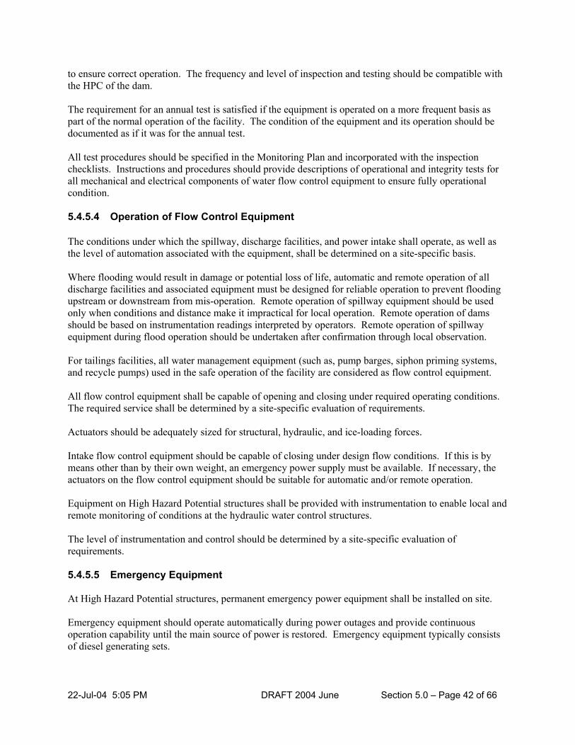
22-Jul-04 5:05 PM DRAFT 2004 June Section 5.0 – Page 42 of 66
to ensure correct operation. The frequency and level of inspection and testing should be compatible with the HPC of the dam. The requirement for an annual test is satisfied if the equipment is operated on a more frequent basis as part of the normal operation of the facility. The condition of the equipment and its operation should be documented as if it was for the annual test. All test procedures should be specified in the Monitoring Plan and incorporated with the inspection checklists. Instructions and procedures should provide descriptions of operational and integrity tests for all mechanical and electrical components of water flow control equipment to ensure fully operational condition. 5.4.5.4 Operation of Flow Control Equipment The conditions under which the spillway, discharge facilities, and power intake shall operate, as well as the level of automation associated with the equipment, shall be determined on a site-specific basis. Where flooding would result in damage or potential loss of life, automatic and remote operation of all discharge facilities and associated equipment must be designed for reliable operation to prevent flooding upstream or downstream from mis-operation. Remote operation of spillway equipment should be used only when conditions and distance make it impractical for local operation. Remote operation of dams should be based on instrumentation readings interpreted by operators. Remote operation of spillway equipment during flood operation should be undertaken after confirmation through local observation. For tailings facilities, all water management equipment (such as, pump barges, siphon priming systems, and recycle pumps) used in the safe operation of the facility are considered as flow control equipment. All flow control equipment shall be capable of opening and closing under required operating conditions. The required service shall be determined by a site-specific evaluation of requirements. Actuators should be adequately sized for structural, hydraulic, and ice-loading forces. Intake flow control equipment should be capable of closing under design flow conditions. If this is by means other than by their own weight, an emergency power supply must be available. If necessary, the actuators on the flow control equipment should be suitable for automatic and/or remote operation. Equipment on High Hazard Potential structures shall be provided with instrumentation to enable local and remote monitoring of conditions at the hydraulic water control structures. The level of instrumentation and control should be determined by a site-specific evaluation of requirements. 5.4.5.5 Emergency Equipment At High Hazard Potential structures, permanent emergency power equipment shall be installed on site. Emergency equipment should operate automatically during power outages and provide continuous operation capability until the main source of power is restored. Emergency equipment typically consists of diesel generating sets.

22-Jul-04 5:05 PM DRAFT 2004 June Section 5.0 – Page 43 of 66
Portable equipment should be identified and accessible when required. This equipment should be driven with a reliable independent source of power. Controls and instrumentation should permit operation and monitoring during power outage conditions for High Hazard Potential structures. In locations where emergency power is not supplied, DC equipment, battery banks, and ancillary equipment should be provided to permit operation of the instrumentation and controls for an eight-hour period. 5.4.5.6 Frequency of Monitoring The frequency of instrument readings or making observations of a dam depends on several factors, including: 1) relative hazard to life and property that the dam presents; 2) height of the dam; 3) reservoir capacity; 4) age of the dam; 5) conditions, such as, seismic activity; 6) special conditions, such as, development in the flood plain; 7) time of the year, such as, spring freshets, etc.; and 8) requirements imposed by regulatory agencies. In general, as each of the above factors increases, the frequency of monitoring should also increase. For example, frequent readings should be taken during high water levels and at the time of significant storms. Frequency of monitoring should be determined for each structure, based on each structure’s specific physical and environmental characteristics, and identified in the Monitoring Plan. 5.4.6 OPERATION, MAINTENANCE, AND SURVEILLANCE MANUAL (OMS
MANUAL) For less complex dam sites, the Operation, Maintenance, and Surveillance (inspection and monitoring) Plans can be documented in a single OMS Manual. 5.4.6.1 Report Sections An OMS Manual typically contains the following report sections, figures, tables, and appendices. 1) OMS report sections include:
a) List of OMS revisions b) Preface or summary
22-Jul-04 5:05 PM DRAFT 2004 June Section 5.0 – Page 44 of 66
c) Introduction – Background d) Watershed description and site location and access e) Description of dam and facilities, such as, hydro plant, fishways, saddle dams, municipal and
private potable intakes f) Objectives of the plan relative to social, economic, and environmental benefits g) Seasonal operating procedures documenting dam manipulations, regulated water level zones, and
discharges h) Operating procedures during flood, emergency, and low flow conditions i) Personnel, tools, and safety procedures j) Records k) Maintenance l) Monitoring and instrumentation
2) Figures
a) Watershed boundary b) Site location and access c) Stage-discharge curves d) Stage-storage curves e) Rule curve (zone(s) of operation)
3) Tables
a) stage-discharge tables b) stage-storage tables
4) Appendices
a) Dam and facility site plans, profiles, and sections (11” by 17” as-built) b) Record (table and/or spreadsheet) of operations c) Record (table and/or spreadsheet) of maintenance d) Record (table and/or spreadsheet) of visual inspections e) Equipment and tools for dam operations f) Maintenance manuals (if applicable)
5.4.7 EMERGENCY PREPAREDNESS PLAN (EPP) 5.4.7.1 General The Emergency Preparedness Plan (EPP) is a formal written plan that identifies the procedures and processes that the dam operators would follow in the event of an emergency at a dam. The emergency could be, for example, failure of essential equipment, such as, flood gates, slope failure having the potential to cause dam failure, or a complete failure of the dam caused by overtopping, earthquake, or piping. By their nature, EPP's are site-specific. Emergencies can arise due to natural or man-made situations, such as, equipment failure, operator error, floods, erosion, fire, washout of access routes, power line failures, etc., and could affect residents and communities upstream and downstream. The EPP describes actions which would be required during emergencies, including notification to downstream communities

22-Jul-04 5:05 PM DRAFT 2004 June Section 5.0 – Page 45 of 66
and sets out the responsibility of the dam owner, municipalities, affected individuals, and agencies. The flood warning and flood response plans form a part of the EPP. Dams having a significant and high HPC must have an EPP. Dams having a very low HPC do not require an EPP. The question of whether a dam poses a hazard to downstream areas and therefore requires an EPP will often be obvious by examination. For example, a large, high-hazard dam retaining a large volume of storage within a confined valley containing significant habitation downstream would clearly need an EPP. Conversely, a low hazard dam in a relatively uninhabited area usually would not. If inhabited areas are potentially affected, an EPP must be prepared. 5.4.7.2 Requirement of an EPP The potential emergencies at a dam shall be assessed, identified (i.e., modes of failure and mis-operation) and evaluated with consideration given to the consequences of failure or mis-operation so that appropriate preventative or remedial actions can be identified and taken.
1) An EPP shall be prepared, tested, issued, and maintained for any dam whose failure could be
expected to result in loss of life as well as for any dam for which advance warning would reduce upstream or downstream damage.
2) In the case of a dam under construction, the approved EPP shall be issued and tested prior to first
filling the reservoir of the dam. 3) A notification process shall be initiated, as specified in the EPP, anytime that an emergency situation
is identified or immediately upon finding a hazardous condition that could potentially lead to a dam breach.
4) The dam owner or operator shall assess whether emergency warnings should be issued directly to
inhabitants in areas immediately downstream of a dam, in addition to emergency response agencies, due to the short period of time before the anticipated arrival of a flood wave.
5) Where preventative actions are available, these actions shall be initiated, as appropriate, to prevent
failure or to limit damages where failure is inevitable. In Ontario, the MNR (in unorganized townships) and Conservation Authorities (where they exist) have the responsibility to warn residents of a flood hazardous situation. Where municipalities exist with no CA’s the flood warning responsibility rests with the municipality. In all cases, their respective responsibilities in this regard should be explicitly defined in the dam owner’s EPP. The warnings would normally be based on the information provided by the dam owner or his operator. The dam owner or operator is responsible for linking appropriate dam surveillance with the emergency response procedures. Normally, provincial or local governments have their own emergency response procedures that would incorporate or include information provided by the dam owner.
For a tailings dam, the EPP prepared by the owner would also document the immediate action required to mitigate the short-term and potential long-term environmental impacts of an unwanted release of the reservoir contents. The failure of a tailings dam could result in impacts ranging from minor to substantial affects on the environment. The level of detail within the EPP should reflect the degree of potential impact.

22-Jul-04 5:05 PM DRAFT 2004 June Section 5.0 – Page 46 of 66
In the case of a cofferdam used in a water body for construction of new works or in the rehabilitation of existing works and where the consequences of failure warrants it, an EPP shall be prepared, issued, and tested prior to impoundment behind the cofferdam. 5.4.7.3 Development of an EPP
1) An EPP shall describe the actions to be taken by the dam owner and operator in an emergency. The
EPP shall assign responsibility for each action to be taken by an individual (identified by organizational position) and/or a backup.
2) The required actions of other agencies and affected parties shall be developed in conjunction with the
dam owner and operator and shall be included in the EPP as appropriate. 3) Copies of the EPP or summaries of relevant information shall be provided to those who have
responsibilities under the plan.
The steps in developing an EPP are generally as follows.
1) Identify those situations or events that would require initiation of an emergency action; specify the actions to be taken and by whom.
2) Identify all jurisdictions, agencies, and individuals who will be involved in responding to the emergency.
3) Identify primary and auxiliary communications systems, both internal (between persons at the dam) and external (between dam personnel and outside agencies).
4) Identify all persons and agencies involved in the notification process, and draft a notification flowchart which shows whom should be notified, in what order, and what actions are expected of downstream agencies.
5) Develop a draft of the EPP.
6) Hold coordination meeting(s) with all parties included in the notification list for review and comment
on the draft EPP.
7) Make any revisions, obtain any necessary regulatory approval, finalize, and distribute EPP.
5.4.7.4 Contents of an EPP Document
The EPP may include the following procedures and information: 1) emergency identification and evaluation; 2) preventative actions (where available); 3) notification procedure; 4) notification list and flowchart; 5) communication systems;

22-Jul-04 5:05 PM DRAFT 2004 June Section 5.0 – Page 47 of 66
6) access to site; 7) response during periods of darkness; 8) response during periods of adverse weather; 9) sources of equipment; 10) stockpiling supplies and materials; 11) emergency power sources, if required; 12) inundation maps; and 13) warning systems (if used). 5.5 BEST MANAGEMENT PRACTICES FOR PUBLIC SAFETY
AROUND DAMS (PSAD) 5.5.1 GENERAL The objective of these Best Management Practices (BMP) are to provide consistent information to MNR field staff involved in providing advice and guidance regarding public safety along provincial waterways as it relates to the potential for drowning, accidental deaths, and serious injuries at and around dams. The review and approval under sections 14 and 16 LRIA does not require the inclusion of the information in this section. Dam owners should be encouraged to take reasonable precautions to safeguard the public from harm at and around the site of a dam. The evaluation and identification of the potential hazards should be conducted on a site-specific basis, as each dam and downstream channel has its own unique characteristics, reservoir size, topography, and recreational uses upstream and downstream. Potential hazards also vary widely requiring a Public Safety Measures Plan to address the potential hazards through the use of signs and other safety devices tailored to suit the unique features of a site. A qualified engineer should be used to evaluate and identify the necessary safety devices. The services of a qualified engineer are not needed if the dam owner is able to document through the Public Safety Measures Plan that the signs as identified in these BMP’s are sufficient in warning the public of the hazards and that no further safety measures are needed. 5.5.2 TYPES OF DAMS FOR ASSESSMENT OF PSAD BMP’S
The PSAD BMP’s apply only to dams identified as follows:
1) any dam that measures more than 3 metres in height;

22-Jul-04 5:05 PM DRAFT 2004 June Section 5.0 – Page 48 of 66
2) any dam that measures 2 metres or more and has a reservoir surface area of 2 hectares or more. The PSAD BMP’s do not apply to mine tailings dams or to dams located on private land on non-navigable watercourses to which there is no public access by land or water. 5.5.3 CONVENTION FOR DESCRIBING THE ORIENTATION OF DAMS In order that Public Safety Measures Plans are consistently interpreted, it is important to define the orientation of an observer viewing the dam and the water flow. The orientation of the observer and the dam should be as follows:
The left and right components of a dam and/or left and right banks of a watercourse should be referenced based on the observer facing in a downstream direction and this reference should be followed in complying with all requirements identified within these BMP’s.
5.5.4 BEST MANAGEMENT PRACTICES (BMP) FOR PUBLIC SAFETY
MEASURES PLANS 5.5.4.1 General
A BMP for a Public Safety Measures Plan (The Plan) should be prepared to identify and document why and where public safety measures are necessary at the dam site, as well as in upstream and downstream areas. The Plan should include the following components:
1) Site Description; 2) Hazards Identification; 3) Safety Measures Identification; 4) Description of the site operating practices; and 5) Inspection, operation, and maintenance schedule for the safety devices. 5.5.4.2 Site Description
The Site Description should include the following information.
1) A detailed map of the location of the dam and its associated appurtenances and surrounding area.
This map should include:
a) the site property boundaries; b) the location of the various hazards identified and assessed; c) the location of all roads, access roads and trails over land, and water leading to areas where the
hazards to the public exist;

22-Jul-04 5:05 PM DRAFT 2004 June Section 5.0 – Page 49 of 66
d) the various types of activities and level of use by the public, including, portages, public beaches, camp grounds, boat launches, snowmobile and hiking trails, scenic outlooks, etc.; and
e) the location and plans and specifications of all the safety devices.
2) Description of each of the component dam discharge facilities, including their stage-discharge rating curves;
3) A drawing indicating the watershed and extent of reservoir inundation; and 4) All additional reports and analyses conducted by the owner and the engineer to determine the location
and types of safety devices and/or safety measures. 5.5.4.3 Hazards Identification
Only those public safety hazard(s) that may exist at the dam site and upstream and downstream, as a result of the existence and operation of the dam or its appurtenances, should be identified. A public safety hazard exists if there is a reasonable potential for person(s) to suffer serious injury, drowning, or death because of the hazard. The plan should document:
1) an inventory of potential hazardous areas at the dam upstream and downstream and provide a detailed
description of the hazards. 2) the types of users that could be affected by these hazardous areas including the access routes taken by
these users. 3) hazard identification and assessment process which includes the rationale for making decisions to
install public safety measures to protect the public.
4) The assessment should include all the areas affected by the dam (at the dam, upstream and downstream) during various water levels, water flows, as well as seasonal changes in the public activities.
5) The degree to which the general public would not recognize the severity of a given hazard should be
taken into consideration in the hazard assessment. 5.5.4.4 Safety Measures Identification Based on the hazard identification, the following Determinant Criteria should be used in the selection of the dam safety measures BMP’s:
1) the extent of public interaction (i.e., level of use, ease of access) at the dam and areas which may be
affected by its operation; 2) the proximity of the dam to designated swimming / recreation areas; and 3) the level of inconvenience that safety measures may cause the surrounding population.
The Plan should identify:

22-Jul-04 5:05 PM DRAFT 2004 June Section 5.0 – Page 50 of 66
1) those hazards that can be eliminated, or 2) the restrictions to control access to the hazard(s) through the use of physical barriers, or 3) where options 1) or 2) above are not practical, the hazards should be addressed based on the
Determinant Criteria by selecting the number and type of safety measures necessary to reduce the potential for drowning, serious injury, and other accidental deaths resulting from the hazards.
The degree to which the general public would not recognize the severity of a given hazard must be taken into consideration in selecting the appropriate dam safety measure(s). The Determinant Criteria that most accurately describes the site and hazard(s) should correspond with the use of the following dam safety measures: 1) eliminate the hazard; 2) Signs; 3) Fences and Railings; 4) Safety Booms and Buoys; 5) Illumination; and 6) Sirens, Warning Lights, and Surveillance Cameras. A Public Safety Measures Plan should include the plans and specifications of all existing and proposed safety measures. 5.5.4.5 Inspection, Operation, and Maintenance BMP Schedule The Plan should include: 1) a schedule for routine inspections and maintenance work required to ensure that the public safety
measures installed or implemented continue to remain operational. 2) procedures, where safety devices are damaged or no longer effective, should be repaired or replaced
as soon as possible. Temporary safety measures should be installed during the repair or replacement period.
3) the frequency of regularly-scheduled inspection and maintenance cycles; in no case should the cycle
be longer than one year. 4) the frequency of scheduled inspections and maintenance cycles that are commensurate (increased)
where the potential hazard is moderate or high. 5) a table of recorded inspections, maintenance work, and all modifications to the safety measures. 6) the operating procedures to be followed when using the dam’s safety measures including their
relationship to the operation of each of the dam discharge facilities.

22-Jul-04 5:05 PM DRAFT 2004 June Section 5.0 – Page 51 of 66
5.5.5 PUBLIC SAFETY BMP MEASURES GUIDELINES See Appendix C for Public Safety BMP Measures Guidelines on signs, railings and fences, booms and buoys, and sirens. 5.6 CRITERIA AND STANDARDS FOR CHANNELIZATIONS 5.6.1 GENERAL Channelization means an alteration to the alignment, width, depth, sinuosity, conveyance, or bed or bank material of a river or stream channel. Dam decommissioning, diversions, ponds excavated in the stream and/or by-pass ponds and retaining walls, embankments, revetments, enclosures, cables, pipelines, and heat loops or other structures that alter existing conditions fall in the category of channelization. Channelization may hold back, forward, or divert water. Therefore, the assessment of existing conditions as well as proposed works will require consulting the following documents for approval requirements. 1) MNR Natural Hazards Technical Guidelines; and 2) MNR Adaptive Management of Stream Corridors in Ontario. A soils investigation is required if a substantial channel realignment is proposed. Channel banks should be stable under saturated conditions, usually not steeper than 2 horizontal to 1 vertical. The bed and the banks should be able to resist scour under extreme flow conditions. Revetments should be placed on safe slopes (two horizontal to one vertical or flatter). Filter materials should be placed under revetments to allow drainage and prevent the escape of fine soils. Wherever possible, the natural channel design approach should be used for channel design. This approach considers the stability of natural systems in which there is continuous movement of bed-load material and biological plant growth (above and below ground) to provide resistance to bank erosion. 5.6.2 DESIGN CONSIDERATIONS 1) Channelization, including diversions, retaining walls, or revetments which will alter the storage or
discharge characteristics of the flood plain of a river, may be designed using the design flood criteria shown for the small size category for dams table 5.3. The PMF is not normally used for channel design. The channel capacity may be designed for less than the 25 year flood, e.g., 10, 5, or 2 year flood, but the combined capacity of the channel and flood plain must meet the design flood criteria for small dams in the table.
Bankfull discharge of a river natural flow channel usually corresponds to the 1:2.33 year to the 1:5 year return period depending upon the stream type and basin conditions.
2) Diversion channels and other types of channelization works shall be designed in accordance with
sound engineering principles. 3) Unless legal authority is obtained to do so, channelization, including diversion channels, shall not
increase flooding damage and/or frequency or increase erosion rates and/or frequency along both

22-Jul-04 5:05 PM DRAFT 2004 June Section 5.0 – Page 52 of 66
sides of, or upstream or downstream of, the proposed channel and shall not lower river levels detrimentally upstream from those existing under natural channel conditions. To meet this criterion, the hydraulic characteristics of a natural river channel and its flood plain and/or of the watershed system shall be maintained in any diversion or channelization of the river or watershed system. This shall apply to all lengths and sizes of diversions and channelization works to prevent a cumulative effect of increased flood levels and/or frequency and increased erosion rates and/or frequency in the river or watershed system due to each additional diversion or channelization. To ensure that the conveyance and storage characteristics of the channel reach are identical to that of the original watercourse, the hydraulic characteristics of the natural watercourse must remain the same in the proposed channel. The following design requirements must be addressed in the submission for approval of channelization works: a) the travel time and therefore the same time-of-concentration of the watershed must be
maintained; b) the stage-discharge relationship in the natural river channel and its flood plain at the design peak
flood flow and the corresponding flood levels must not be greater than existing conditions
c) the stage-storage relationship of the natural river channel and its flood plain must be compared to the proposed channel and resulting flood plain in 30 cm channel elevation increments from channel bed up to the design flood level to ensure that the flood plain storage will not to be decreased at any water level.
Example 1
i) If the river channel only (not flood plain) is to be totally diverted (relocated), the new
channel should have a length, slope, cross-sectional area, and roughness coefficient sufficient to maintain the above 3 hydraulic characteristics.
OR
ii) If the new channel must be shorter than the existing channel being replaced, then it must
have a larger cross-sectional area to maintain the same channel storage volume and a lower water velocity to maintain the same travel time.
Example 2
If both the river channel and the flood plain are to be totally diverted or altered or if the river channel is to be channelized, there must not be any increase and/or change in:
i) the design peak flood level as compared to the existing channel and its flood plain; and
ii) the stage-storage relationship in 30 cm elevation increments as compared to the existing
channel and flood plain or in floodwater detention areas in the watershed above or immediately below the site.

22-Jul-04 5:05 PM DRAFT 2004 June Section 5.0 – Page 53 of 66
The above criteria ensures that the conveyance and storage capacity of the channelized reach is identical to that of the original watercourse.
Exceptions to the criteria of maintaining identical hydraulic properties may be considered where:
i) the objectives of the criteria are met if the cumulative impacts of all future works in the watershed are quantified through sub-watershed studies and are considered insignificant.
ii) there are no downstream impacts (i.e., channel outlets into and the flow is retained by a lake and/or reservoir).
iii) the discharge-storage relationship of the watercourse is maintained on an incremental basis
for all floods (from the 2 year return flood to the flood per provincial standards for defining natural hazards).
iv) routing calculations that demonstrate that there would be no increase in downstream peak
flows and total storage has been maintained or increased.
4) Permissible water velocities shall be not be greater than those listed in table 5.8. 5) Alignment of the channel should be curvilinear wherever possible to reduce flow velocities and
maintain natural conditions. 6) Side slopes of channels shall be constructed with slopes that will remain stable under saturated
conditions. Side slopes should be no steeper than one vertical to two horizontal or flatter for most soils. The river bed and embankments should be able to resist scour under extreme events. Filter materials should be placed under revetments to allow drainage and to prevent the escape of fine soils.
7) If a channel is proposed where velocities at flows up to and including design flood flow are above the
upper limit permitted, means (such as, weirs or drop structures) must be provided to dissipate energy and reduce water velocity to the permissible level.
8) Erosion protection using bio-engineering techniques or riprap or equivalent material should be placed
on side slopes of diversion channels at bends and other locations where flow velocity will be at or will exceed the maximum permissible velocity to prevent erosion and shall extend from the tie of the slope to the high-water level.
9) Diversion banks (side slopes) above the normal water surface shall be protected from erosion from
surface run-off by placement of sod or by the planting of grass using a bio-engineering fiber mat or other approved means of limiting erosion until a satisfactory sod is created.
10) Fish habitat existing in the natural channel that will be cut off or otherwise destroyed by the
construction of the new channel shall be created in the new channel in accordance with the advice of the District Biologist and/or Fish and Wildlife Supervisor.
11) Bed material equivalent to that existing in the natural channel at the diversion location shall be placed
in the bed of the diversion channel in accordance with the advice of DFO. 12) Shade-creating vegetation (trees and/or bushes) to provide a shaded water area not less than that
existing on the natural stream at the diversion shall be planted on the banks of the diversion in accordance with the advice of the area team biologist.

22-Jul-04 5:05 PM DRAFT 2004 June Section 5.0 – Page 54 of 66
13) Construction of the diversion channel must be carried out in such a way that sediment is controlled during the construction period. This may require that a settling basin with an outlet filter be used to stop downstream movement of sediment.
14) The diversion channel shall be constructed in the dry, that is, with no flow through it and shall not be
opened during the spawning periods for migratory or permanent species of fish in the river as determined by the Area Biologist and DFO.
Table 5.7: Permissible Channel Velocities
Maximum Permissible Velocity (m/s) Original Material
Excavated for Channel
Clear Water, No Detritus
Water Transporting
Colloidal Silts
Water Transporting Non-colloidal Silt, Sands,
Gravel, or Rock Fragments
Fine sand (non-colloidal) 0.46 0.76 0.46
Sandy loam (non-colloidal) 0.53 0.76 0.61
Silt loam (non-colloidal) 0.61 0.91 0.61
Alluvial silts (non-colloidal) 0.61 1.07 0.61
Ordinary firm loam 0.76 1.07 0.69
Volcanic ash 0.76 1.07 0.61
Fine gravel 0.76 1.52 1.14
Stiff clay (very colloidal) 1.14 1.52 0.91
Graded, loam to cobbles (non-colloidal) 1.14 1.52 1.52
Alluvial silts (colloidal) 1.14 1.52 0.91
Graded silt to cobbles (colloidal) 1.22 1.68 1.52
Coarse gravel (non-colloidal) 1.22 1.83 1.98
Cobbles and shingles 1.52 1.68 1.98
Shales and hardpans 1.83 1.83 1.52
Note:
The above velocities are for straight channels. Multiply velocities by 0.9 for slightly sinuous channels, 0.95 for moderately sinuous channels, and 0.85 for highly sinuous channels. 5.6.3 RETAINING WALLS AND EMBANKMENTS Retaining wall designs should take into account active and passive soil pressures and the unit weights of the soil. The backfill material must be free-draining and relief drains must be provided in the structure if the unit weights are based on dry conditions. Rigid structures must be founded below the frost line and set back from the channel bed on a slope of 2 horizontal to 1 vertical (2H:1V) or flatter. Scour velocities must be determined and checked to avoid undermining. The alignment of embankments and retaining walls should not cause currents to impinge on and erode unprotected banks.

22-Jul-04 5:05 PM DRAFT 2004 June Section 5.0 – Page 55 of 66
Embankments, including berms, dykes, or abutments, that encroach into rivers or streams can only be considered if the district biologist and DFO provide input and acceptance. For example, compensating excavation could be carried out to maintain the flow-storage characteristics if the stream and the fisheries issues are addressed. Embankment soils should consist of clean fill, free of deleterious materials. The foundation soils should be capable of supporting the weight of the embankment. Slopes for earth embankments should be no steeper than 2H:1V. Rock-fill embankments can have steeper slopes, typically 1.5H:1V. Like revetments, stable slopes typically require filter material to separate the large and small particles, allow drainage at various water levels, and prevent the escape of fine soils. Granular(s) or synthetic (geotextile) materials can be used between riprap and native soil. 5.6.4 BY-PASS PONDS
Ponds are a form of channelization that increase the water surface area and depth of the channel. On-stream ponds are generally discouraged because of the thermal impacts on fish habitat. Ponds off-line but located parallel to the main channel with an inlet and outlet to the stream constitute a type of diversion called by-pass ponds. The inlet and outlet connections are often made with pipes. Embankments are often added to by-pass ponds to increase the water depth. Embankments must be safe from over-topping and anti-seepage collars installed on pipes through embankments.
1) Structural integrity of dams or dikes (embankments) between the pond and stream should be assessed
using similar procedures as for dams in section 5.3. 2) No more than one-third of the streamflow may be diverted through the pond at any time. 3) The inlet to the pond must be equipped with a shut-off valve or gate. 4) If located on a coldwater stream, the outflow must be through a bottom draw-off with entry to the
draw-off at a minimum pond depth of 3 metres. 5) If located in the headwater area of a coldwater stream, the surface area of the pond should not exceed
0.4 hectares or 1 acre. 6) Approval shall be subject to the operating condition that the inlet gate be closed during summer
periods if the water temperature of a coldwater (trout) stream downstream of the pond outlet is increased due to the by-pass pond.
5.6.5 ENVIRONMENTAL CONSIDERATIONS
Channelization of natural streams can have serious adverse impacts on the natural channel and on the environment. Diversions that take all stream flow from a natural to an artificial channel environment may be particularly damaging. A range of environmental impacts and mitigation measures should be considered and assessed for channelization projects, as outlined below:

22-Jul-04 5:05 PM DRAFT 2004 June Section 5.0 – Page 56 of 66
1) Fish habitat loss is a prime concern with channelization works and their associated artificial channel features, such as, drop structures which may impede fish movement.
2) A diversion from one watershed to another can have serious implications and should not be
contemplated without an environmental assessment. 3) Channels should be constructed using natural channel design principles. 4) A river system depends on the main channel to carry the bankfull flow (1:2.33 to 1:5 runoff events)
and the flood plain to convey the larger portion of a flood event. 5) Channels in their natural form depend on vegetation to protect banks. Hardening of channels with
walls or revetments should be minimized. Bioengineering techniques should be used wherever possible.
6) Channels that are designed to simulate natural forms, such as, pool and riffle formations, will provide
enhanced ecological benefits. 7) Channelization may be improved by adding fish structures, such as, deflectors and root wads.
8) In-stream ponds and by-pass ponds cause warming and evaporation losses. These can be reduced by
shade plantings. 9) Ponds with a surface area greater than 0.4 ha should not be considered on the headwaters of a
coldwater stream (depends on fish species and downstream water body). 10) Fish that are stocked in by-pass ponds should be kept out of the main stream by screens. 11) Ponds, or parts of ponds, may tend to become stagnant and form algae. Straw-wheat bales can be
submerged along the waters edge to help control algae growth. 12) Ponds should be designed to promote circulation and avoid stagnancy. 5.6.6 ENCLOSURES
Enclosures are similar to culverts (see water crossings) and channelizations. A culvert longer than 20 metres is considered an enclosure. Enclosures are constructed to cover streams, usually to allow development to take place on the surface. Pipes installed on small streams are typical enclosure candidates. The environmental impacts are basically the same as those with culverts and channelization but are likely to be more severe. Large sections of streams can be effectively sterilized by enclosures and lose all ability to provide fish passage, other water resource dependent habitats, and other amenities. The criteria for water crossings and other channelization works should be used for the review of enclosures.

22-Jul-04 5:05 PM DRAFT 2004 June Section 5.0 – Page 57 of 66
5.6.7 BURIED PIPELINES OR CABLES
Approvals are required under the LRIA for buried pipelines that are installed by excavation of the streambed. The area in which damage can be caused to the stream is often relatively small. The excavation of the streambed is identical to a channelization project involving lowering the streambed for a very short distance. Excavation for a pipeline or cable is backfilled when the installation is complete. Pipeline and cable projects usually involve clearing and trenching of the banks and areas adjacent to the stream potentially leading to increased sedimentation and possible increased backwater. Erosion and Sediment Control measures should be applied. 5.7 CRITERIA AND STANDARDS FOR WATER CROSSINGS 5.7.1 GENERAL
A water crossing, as defined in Ontario Regulation 454/96, means a bridge, culvert, or causeway that is constructed to provide access between two places separated by water but that also holds back, forwards, or diverts water. Water crossings, including channels and drainage systems (conveyance and overland), must be designed such that there is no damage to a third party during the design flood event. The most effective drainage system would generally consist of:
1) a conveyance system to pass the flows generated by more frequent floods through pipes, culverts, and
bridge openings; and 2) a secondary system which will pass overland flow flood waters over a depression in the roadway
when the capacity of the convenience system is exceeded. 5.7.2 WATER CROSSINGS REQUIRING APPROVAL Approval, where required, shall not be deemed to include approval of the structural integrity of the bridge and shall be so stated in the plans and specification approval letter. Channel alterations required in connection with the structure shall be in accordance with section 5.6. Water crossings causing problems should be brought to the attention of the appropriate authority for resolution. 5.7.3 DESIGN FLOOD MAGNITUDES
1) Criteria for assessment of the design flood magnitude for private bridges, culverts, and causeways
must be in accordance with those of the Ministry of Transportation and Communications.
The following table provides minimum design flood standards for road crossings.
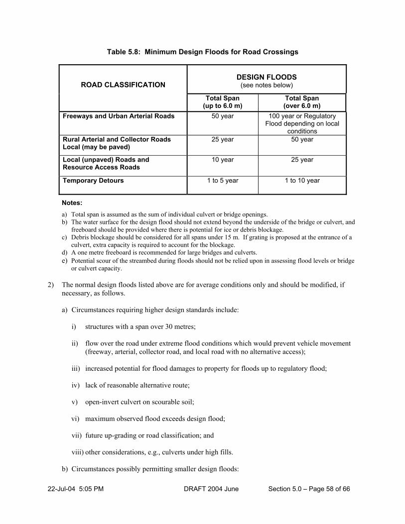
22-Jul-04 5:05 PM DRAFT 2004 June Section 5.0 – Page 58 of 66
Table 5.8: Minimum Design Floods for Road Crossings
DESIGN FLOODS
(see notes below)
ROAD CLASSIFICATION
Total Span (up to 6.0 m)
Total Span (over 6.0 m)
Freeways and Urban Arterial Roads 50 year 100 year or Regulatory Flood depending on local
conditions Rural Arterial and Collector Roads Local (may be paved)
25 year 50 year
Local (unpaved) Roads and Resource Access Roads
10 year 25 year
Temporary Detours 1 to 5 year 1 to 10 year
Notes: a) Total span is assumed as the sum of individual culvert or bridge openings. b) The water surface for the design flood should not extend beyond the underside of the bridge or culvert, and
freeboard should be provided where there is potential for ice or debris blockage. c) Debris blockage should be considered for all spans under 15 m. If grating is proposed at the entrance of a
culvert, extra capacity is required to account for the blockage. d) A one metre freeboard is recommended for large bridges and culverts. e) Potential scour of the streambed during floods should not be relied upon in assessing flood levels or bridge
or culvert capacity.
2) The normal design floods listed above are for average conditions only and should be modified, if necessary, as follows.
a) Circumstances requiring higher design standards include:
i) structures with a span over 30 metres; ii) flow over the road under extreme flood conditions which would prevent vehicle movement
(freeway, arterial, collector road, and local road with no alternative access); iii) increased potential for flood damages to property for floods up to regulatory flood; iv) lack of reasonable alternative route;
v) open-invert culvert on scourable soil; vi) maximum observed flood exceeds design flood; vii) future up-grading or road classification; and
viii) other considerations, e.g., culverts under high fills.
b) Circumstances possibly permitting smaller design floods:

22-Jul-04 5:05 PM DRAFT 2004 June Section 5.0 – Page 59 of 66
i) unusually low traffic volume for class of road; ii) future down-grading of road classification; iii) summer use only (if relief flow over roadway is possible in larger floods); and iv) other considerations.
c) Use of Regulatory Flood
Design to Regulatory Flood criteria is to be considered if, under Regulatory Flood conditions, a facility designed to normal criteria would:
i) materially increase flood damage to buildings over that which would occur under existing
conditions at the site, or ii) create a backwater which would materially reduce the area of developable land upstream,
provided that building development is expected within 20 years.
In all cases the probable benefit, tangible and intangible, should be commensurate with the added cost of the facility and should be discussed with the municipality and with the landowners adversely affected.
3) To minimize the size of the structure, full account should be taken of relief flow over the roadway
(except where the Regulatory Flood is the design flood) up to the maximum allowable backwater dictated by existing conditions and of any other means of reducing the backwater caused by the structure.
5.7.4 STRUCTURAL AND LOADING
The primary purpose of the review of water crossings is to ensure that there are no negative hydraulic and environmental impacts as a result of constructing the structures. Structural reviews are not carried out for water crossings unless a water crossing and associated works such as embankments act like a dam and hold back water. In this circumstance, the water crossing should be reviewed in the same manner as a dam. Small bridges and culverts should be based on standard engineering designs and may use standard pre-manufactured components, such as, corrugated metal pipes. Bridges must be designed by a qualified engineer. Public water crossings having clear spans of 3 metres or more, from bearing support to bearing support, must be designed following the Canadian Highway Bridge Design Code CAN/CSA-S6-00, or latest version. Private water crossings located on or deemed to have the potential of affecting Crown Land must also abide by the Crown Land Bridge Policy (i.e., bridges over provincial Crown Land). Buckling in thin wall culvert pipes under buoyant conditions (uplift) can be a problem. Appropriate counter-measures include anchoring to headwalls, covering culvert ends with sloping fill material, as well as ensuring adequate flow capacity through regular maintenance to clear debris.

22-Jul-04 5:05 PM DRAFT 2004 June Section 5.0 – Page 60 of 66
5.7.5 SOILS AND FOUNDATIONS Rigid structures should be founded below the frost line with the footing designed to spread the load according to the allowable bearing strengths. Footings may be supported on pilings if they are designed to meet the code CAN/CSA S6-00. Retaining wall designs should take into account active and passive soil pressures and unit weights of the soil. The backfill material must be free-draining and relief drains provided in the structure if unit weights are based on dry conditions. Soil around culverts must be carefully placed and compacted in thin layers. Cut-off walls are used along culverts to prevent piping. Headwalls and aprons are used to prevent erosion at the entrance and exit. The alignment of bridges or culverts should not cause currents to impinge and erode embankments. Soil for causeways should be suitable for placing in water and remain stable in water. Riprap or similar material should be placed around the waterline to prevent erosion from high velocities. 5.7.6 ENVIRONMENTAL CONSIDERATIONS
Water crossings may directly affect fish, wildlife habitat, and water quality. The design and construction phases of a water crossing must be carefully planned to properly locate the crossing to avoid releasing sediment into a watercourse. The MNR Environmental Guidelines for Access Roads and Water Crossings should be consulted for requirements of approval for water crossings under the LRIA. The selection of the type of structure depends on several factors like site conditions, biological sensitivity, hydraulic characteristics, transportation requirements, and cost. Bridges have several environmental advantages over culverts because they span the waterway avoiding obstructions to fish movement and in-water disturbances during construction. Site conditions suitable for bridge construction include: 1) narrow water width; 2) rock foundations for abutments; 3) erosion-resistant soils; and 4) shallow water depths. At rapids or riffles, the bridge length should be selected to clear span the bankfull channel with the bridge deck of sufficient height off the streambed to provide the required discharge capacity. The number of piers required to break a bridge span should be kept to a minimum. A culvert is typically used for water crossings with smaller drainage basins. The corrugated steel pipe is the most common type with the open-bottomed arch pipe preferred as a means of protecting fish habitat values. Site conditions suitable for a culvert water crossing include:

22-Jul-04 5:05 PM DRAFT 2004 June Section 5.0 – Page 61 of 66
1) stream reaches with low sinuosity so that the straight pipe will fit the channel; 2) water depth less than half the pipe diameter and less then 1 metre at the time of installation; 3) streambed slope less than 0.5 percent and flow velocities less than 0.5 metres/second; 4) a fine-grained substrate to provide suitable bedding (gravel or finer); 5) a stable foundation that is free of boulders or bedrock and will not settle unevenly when the roadfill is
placed over the pipe in the streambed; and 6) a water surface width comparable to the culvert span. Normal or typical culvert installation practices can be followed if the streambed has a slope of 0.5 percent or less. Good design practices to achieve fish passage include: 1) design the culvert with an opening to pass the design flood; 2) install the culvert on a flat gradient; and 3) embed the culvert at least 10 percent of its diameter below the streambed elevation with at least a 20
cm depth of water. The embedded culvert design is to allow the installation of round or semi-arched culverts on low to moderate gradient fish migration routes. The pipe is set deeply into the stream in order to allow substrate material to form and stay in the bottom of the culvert. It is used where streambed slopes exceed 0.5 percent, but is less than 3.5 percent. Primary design requirements include: 1) select the culvert diameter to be at least 1.25 times the bankfull channel width; 2) install the culvert on a flat gradient; 3) sink the downstream invert at least 20 percent of the culvert diameter below the streambed; 4) the cross-sectional area (sq. m.) above the expected substrate level must be equal to or larger than the
culvert size (sq. m.) required to pass the design flood. 5) field surveys are required to obtain data for design purposes, such as, natural channel bed width and
the natural channel slope. 6) placement of material to simulate the natural substrate is required. On smaller culverts, filling by
natural bed-load movement may be the only practical method. The embedded culvert can only be considered where the product of channel slope and culvert length does not exceed 20 percent of the culvert diameter. Beaver dams can be a problem at culvert sites. Beavers can take advantage of the constricted waterway and build a dam leading to blockage and increased water levels. The need for corrective action depends on the circumstances. A solution that has been successful in some areas is to construct a submerged discharge system which by-passes the dam.

22-Jul-04 5:05 PM DRAFT 2004 June Section 5.0 – Page 62 of 66
5.8 CRITERIA AND STANDARDS FOR EROSION AND SEDIMENT CONTROL
5.8.1 GENERAL
Sediment introduced into streams and rivers from construction sites can be harmful to fish and the environment. In-water construction of dams, channels, ponds, pipelines, and other structures require the implementation of an erosion and sediment control plan. The MNR Environmental Guidelines for Access Roads and Water Crossings – Section 7 – Erosion and Sediment Control should be consulted for requirements for Plans and Specifications approval. It is the responsibility of the dam owner and the owner’s contractor to exercise due diligence in order to prevent unauthorized harmful alteration, disruption or destruction of fish habitat, the impairment of water quality, and other adverse impacts on the environment. Due diligence requires using appropriate designs, materials, construction practices, mitigation techniques, and monitoring. At certain times of the year, fish are more vulnerable to harm from sediment than at other times. The risk to fish can be reduced considerably by scheduling construction outside the fish spawning, incubation, and fry emergence times. This occurs at different times of the year for different fish species. The District Area Supervisor shall provide information on the aquatic resources to be protected on the water body and times of the year when in-water construction is acceptable.
Erosion and sediment must be effectively controlled at all times. This means that the constructor must minimize the impact by reasonable use of erosion and sediment control measures. All projects approved under the LRIA must be built so that any sediment introduced during construction will be reduced to the lowest practical amount. This is achieved by using Best Management Practices (BMP’s). Potential long-term impacts must be eliminated through site stabilization. Although short-term impact may be unavoidable, most streams will recover as high flows flush the sediment downstream to natural settling areas (ponds or lakes). The adverse impacts of erosion and sediment can be avoided by good planning and control. Erosion is a two-part process. First is the loosening of soil particles and second is their transportation by flowing water or wind. Erosion rates are affected by precipitation (duration and force of loosening agents), soil characteristics (susceptibility to erosion), topography (slope and force of erosion and transporting agent), and ground cover (vegetation). Erosion control treatments must address at least one of these factors to be effective. 5.8.2 BEST MANAGEMENT PRACTICES Best Management Practices (BMP’s) for erosion and sediment control must be followed during the planning, design, construction, and monitoring phases. Although there are many BMP's to choose from, the selection of BMP’s must suit the particular construction site.
Control of erosion and sediment requires a risk management approach. What is the worst that can happen? What are the consequences? What is the likelihood that it will happen? The consequences

22-Jul-04 5:05 PM DRAFT 2004 June Section 5.0 – Page 63 of 66
may include damage to the fish resource resulting in charges, convictions, and restoration orders. The MNR recommends the practices shown below to achieve satisfactory erosion and sediment control. These practices are effective, practical, and can be implemented at relatively low cost.
5.8.2.1 Best Management Practices in Planning and Design
1) Include sediment control measures in all project stages, including the conceptual design. In addition,
the need for sediment control measures should be considered when evaluating alternatives, e.g., a long, single-span bridge that requires no work in water may be preferred over a multiple span.
2) Fit the water-crossing approaches to the terrain to reduce cut and fill grading.
3) Identify construction methods and erosion and sediment control issues that may arise. 4) Consider how streamflow will be managed during construction. For example, when placing a small
culvert, will the pipe be installed in flowing water or will a temporary by-pass channel be used? If it is a complex project or if there is a high risk to fish habitat, the sub-contractors should be provided with draft work staging sequences and include erosion and sediment control details at each stage.
5) Provide permanent, end-of-construction erosion control techniques to ensure that the area will be
stable before and after equipment moves off site. 6) Schedule grading and construction activities to minimize the duration of soil exposure. Winter is not
a good time to do construction near water. If work cannot be scheduled at another time, special care must be taken to ensure that erosion and sediment will be under control by spring.
5.8.2.2 Best Management Practices in Construction Administration
1) Assign clear accountability for sediment control to named individuals (e.g., planning, monitoring, and
response to problems). 2) Use experienced contractors for work in water. 3) Encourage the contractor’s input to erosion and sediment control planning. 4) Conduct ‘tailgate’ training for all workers to review planned erosion and sediment control measures,
including the reasons that they are important. 5) Have contingency plans and extra materials on site or readily available on short notice in case of
heavy rainfall.
6) Delay work in wet weather, especially if the creek or river is at flood stage when work in water is scheduled.
7) Work in a continuous manner and install erosion controls as early as possible. 8) Use regular inspection and maintenance procedures to ensure that erosion and sediment control
measures are working.

22-Jul-04 5:05 PM DRAFT 2004 June Section 5.0 – Page 64 of 66
5.8.2.3 Best Management Practices for On-land Stormwater Erosion and Sediment Control
1) Select mitigation techniques that will be effective for the particular type of erosion to occur (e.g.,
splash, sheet, rill, gully, channel). 2) Divert flow away from exposed soil by using diversion berms and/or interceptor ditches. 3) Slow down flowing water to reduce erosion and allow sediment to settle out close to its source
through the use of such techniques as silt fences, rock check dams, and multiple silt fences. 4) For larger drainage areas, direct the flow into channels that are protected from erosion. Channels
must be adequately sized and include lining, check dams, transition sections, and energy dissipaters as necessary. Also, detention ponds should be considered to settle out soil particles before entering the channels.
5) Use coarse granular soil or other erosion-resistant material for fill placements near water. 6) Grade disturbed soils to a stable angle then apply a seed mixture that is appropriate to the work site
area; fertilize and mulch to encourage early re-vegetation. Vegetation will provide long-term, self-perpetuating, and flexible erosion control and, therefore, it is the key component in site stabilization. Bioengineering techniques should be used for stream bank stabilization where possible.
7) Install soil coverings if immediate erosion control is required (i.e., by using erosion blankets, woody
debris mulch, riprap, etc.). 5.8.2.4 Best Management Practices for Construction Work in Water
1) In-water works should be done quickly and in a sustained manner to minimize the amount of in-water
time. 2) When work in water is expected to last more than a day or two, flowing water should be separated
from the work areas. Techniques include silt fences fastened to posts, floating silt curtains, temporary by-pass channels, damming and pumping flow around the work site, and erosion-resistant cofferdams (i.e., steel-sheet pile or similar).
3) Choose materials which are placed in water to minimize sediment transported downstream. It is a
good practice to use materials that are coarser than the existing streambed material. Materials for restoring stream substrate should be stable under flood flows as well as suitable for fish.
4) Clean diverted, water-carrying sediments using a settling basin or filter bag prior to discharging back
into the stream. 5.8.3 SEDIMENT CONTROL PLANNING
Sediment control plans are effective tools for regulators and constructors to ensure that sediment is kept under control. These plans are especially important for works where there is a high risk of harm to fish habitat. Sediment and erosion control plans are used to:

22-Jul-04 5:05 PM DRAFT 2004 June Section 5.0 – Page 65 of 66
1) assist in establishing the construction sequence, 2) identify operations that could cause sediment to enter the water body, and 3) identify measures that will be taken to control erosion and sediment. The benefits of using sediment control plans include the following. 1) The plan preparation process encourages advance thinking to control sediment and identify mitigation
measures. 2) The use of a plan may allow more flexibility as to the timing of the work (i.e., spawning or incubation
period). 3) The plan provides a mechanism to ensure that clear instructions are provided to workers on site and
defines performance criteria that can be monitored. 4) Review and approval of the plan before construction helps establish due diligence defense if the plan
is followed. 5) Owners and regulators are assured that administrative controls are in place to keep environmental
impacts within expected levels.

22-Jul-04 5:05 PM DRAFT 2004 June Section 5.0 – Page 66 of 66
5.9 FLOW CHART FOR PLANS AND SPECIFICATIONS APPROVAL The following chart provides a reference to the sequence and pertinent sections for site location approval.
TABLE 5.9: FLOW CHART FOR PLANS AND SPECIFICATIONS APPROVAL
INFORMATION REQUIRED WITH ALL APPLICATIONS FOR
APPROVAL
IS PROFESSIONAL ENGINEER REQUIRED
FOR PLANS?
Professional Engineer Required
Section 2.3
Professional Engineer Not Required
Refer to Section 2.3
CRITERIA AND STANDARDS DAMS
Section 5.3
CRITERIA AND STANDARDSCHANNELIZATION
Section 5.7
CRITERIA AND STANDARDSWATER CROSSINGS
Section 5.6
OPERATIONS, MAINTENANCE, SURVEILLANCE AND
EMERGENCY PREPAREDNESS PLANS
Section 5.4
PUBLIC SAFETY AROUND DAMS
Section 5.5
CRITERIA AND STANDARDS EROSION AND SEDIMENT CONTROL
Section 5.8

Lakes and Rivers Improvement Act Technical Guidelines – Criteria & Standards for Approval
APPENDIX A: DESIGN FLOODS A-1.0 GENERAL A design flood is used as a design standard for a dam, channelization, and water crossing or similar structure or works. It is the flood for which protection is to be provided against. The level of protection is consistent with the value of human life, property, and the environment that could be damaged or destroyed downstream resulting from failure or mis-operation of these works or as a result of flooding upstream by these works.
Protection of human life, upstream and downstream property, and the environment and any land to be developed in the future (20 year horizon) are main considerations in selecting the flood to be safely passed by the works. The level of protection to be provided is outlined in Section 5.0. The design standards are minimum standards and higher standards should always be considered. The risk of the design flood being equaled or exceeded during the service life of the structure is given by the following equation.
r = 1-(1-1/T)L
Where r is the risk probability, T is the design flood return period, and L is the service life. The following Table A.1 provides the tabular results.
Table A.1: Risks for Various Design Floods and Service Lives
Service Life of Structure (years) 25 50 75 100 Design Flood
return period (years)
Risk Probability (%)
1000 2.5 4.9 7.2 9.5 900 2.7 5.4 8.0 10.5 800 3.1 6.1 9.0 11.8 700 3.5 6.9 10.2 13.3 600 4.1 8.0 11.8 15.4 500 4.9 9.5 13.9 18.1 400 6.1 11.8 17.1 22.1 300 8.0 15.4 22.2 28.4 200 11.8 22.2 31.3 39.4 100 22.2 39.5 52.9 63.4 50 39.7 63.6 78 86.7 25 64.0 87.0 95.3 98.3
As an example, using the above table, the risk involved of a flood occurring of equal or greater magnitude than a design flood of a 100 year return period within an intended life of the structure of 50 years is approximately 40 percent. To reduce the risk of failure to approximately 5 percent, a 975 year design flood would have to be used. See the same information plotted as a graph in Figure A.1
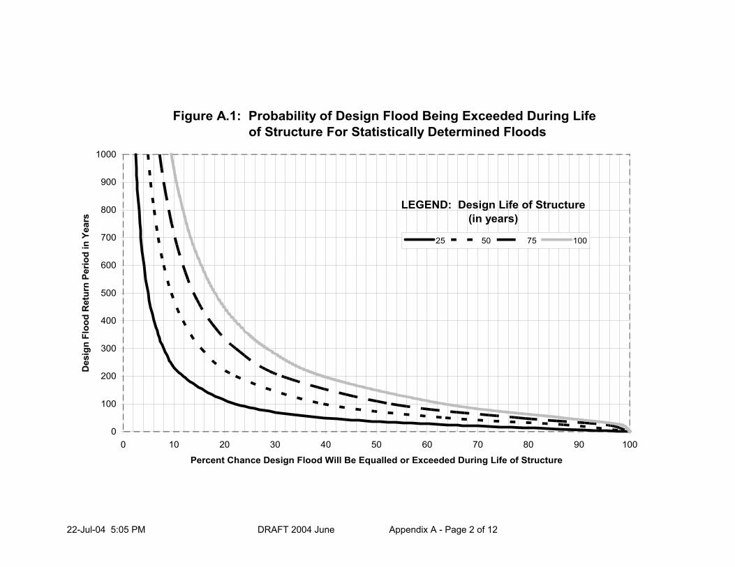
22-Jul-04 5:05 PM DRAFT 2004 June Appendix A - Page 2 of 12
Figure A.1: Probability of Design Flood Being Exceeded During Life of Structure For Statistically Determined Floods
0
100
200
300
400
500
600
700
800
900
1000
0 10 20 30 40 50 60 70 80 90 100
Percent Chance Design Flood Will Be Equalled or Exceeded During Life of Structure
Des
ign
Floo
d R
etur
n Pe
riod
in Y
ears
25 50 75 100
LEGEND: Design Life of Structure(in years)

22-Jul-04 5:05 PM DRAFT 2004 June Appendix A - Page 3 of 12
A-1.2 PROCEDURES FOR DESIGN FLOOD DETERMINATION The methods for determining design floods are:
1) Rational Method: suitable for small watersheds under 25 km
2) Frequency Analysis: statistical analysis of stream gauge data
3) Regional Extrapolation: using frequency analysis data from other parts of the watershed or similar watersheds
4) Region Analysis Methods: using regional equations and index methods
5) Hydrograph Simulation: used for Regulatory Storms and Probable Maximum Flood to calculate flood hydrographs. May also be used to determine an inflow design flood hydrograph for reservoir routing. Can also be used on urban watersheds where there are no stream gauges and regional analysis methods are unsuitable.
A-1.2.1 Rational Method
This method uses the empirical equation:
Q = 0.0028 A.I.C
Where Q is the peak flow, metres3/second, A is the drainage area in hectares, I is the average rainfall intensity in millimeters/hour, and C is the runoff coefficient.
The Rational Method requires calculation of the time of concentration for the drainage area. The average rainfall for the time of concentration is determined from rainfall intensity duration curves. Intensity Duration Frequency (IDF) curves have been calculated for rainfall stations in the Province of Ontario for various return frequencies. The return frequency to be used is the same as the design flood, e.g., 100 years. The runoff coefficient is based on the soil types and land use. A full description of the rational method is contained in the Drainage Manual, Ontario Ministry of Transportation.
A-1.2.2 Frequency Analysis
Statistically-determined floods are defined by the average interval of time (return period) between the occurrence of a peak flood flow equal to or greater than a specified peak flood flow. It is usually expressed in years, i.e., 25, 50, or 100 year return period flood (or 25 year recurrence interval or 1 in 25 year flood frequency or 25 year flood). It is of lower magnitude than the Hazel or Timmins floods or the Probable Maximum Flood (PMF) with the exception of the 100 year flood in certain watershed size ranges. The more frequent the occurrence of a flood, i.e., the smaller the return period, the smaller its magnitude. Maximum instantaneous annual flows for the period of record are used at a gauging station. Peak stream flows may be produced from runoff from rainfall, snowmelt, or a combination of both. Stream gauge flow records are available from Water Survey of Canada for many rivers in the Province of Ontario. A distribution technique is used to fit the data and then extrapolate to the required design flood frequency. The recommended distributions are the Log Normal, Log Normal 3 Parameter, and Log Pearson Type 3. For details, consult Adaptive Management of Stream Corridors in Ontario - Rivers & Stream Systems, Flooding Hazard Limit Technical Guide.

22-Jul-04 5:05 PM DRAFT 2004 June Appendix A - Page 4 of 12
A-1.2.3 Regional Extrapolation
If there is a stream gauge located upstream in the watershed, the hydrographs producing peak flows can be analyzed and routed to the site of interest. A frequency analysis of flows at the site is carried out to determine the design flood. Simple proportioning techniques can also be used to obtain the flow at the site. If there are a number of gauges in the watershed or in adjacent watersheds, regression equations can be developed to determine the relationship between the drainage area and the return period flood. More sophisticated regression analyses incorporate other watershed factors into the relationship, such as, length and slope as well as area.
A-1.2.4 Regional Analysis Methods These are similar to the above regional extrapolation but use regional equations that have been calculated (predetermined) for various parts of the province. Available methods are: 1. Modified Watershed Index Method: Ontario Ministry of Transportation
2. Regression Method: Ontario Ministry of Natural Resources (based on a study by Cumming Cockburn and Associates Ltd.)
3. Index Flood Method: Environment Canada, Ontario Ministry of Natural Resources (Moin and Shaw, 1985)
4. Multiple Regression Method: Environment Canada, Ontario Ministry of Natural Resources (Moin and Shaw, 1985)
A-1.2.4 Hydrograph Simulation Hydrograph simulation is used to determine the maximum resulting runoff of a design storm centered over the watershed above the point of interest. On many small watersheds only a short period of record or no stream flow records are available at or near the site of interest. In these cases, statistically determined storm rainfall, i.e., 25, 50, 100 year return period rainfall from rainfall records in the area, may be used to derive the associated synthetic flood hydrograph for determination of the design storm over the watershed. Storm rainfall depths for various durations and frequencies may be obtained from point rainfall intensity-duration frequency data. See Atmospheric Environment Service, Environment Canada Publications. Unit hydrographs are determined for each increment of runoff (i.e., rainfall converted to runoff using infiltration loss equations). The composite hydrograph is calculated by adding these unit hydrographs for each increment. The shape of the unit hydrograph is based on the time to peak and regression time relationships for the watershed. Standard equations may be used to determine hydrograph shape factors. Hydrographs based on return period rainfall may also be adjusted to match the peak with a given return period flow. This can be done by adjusting inputs such as loss factors and hydrograph shape parameters. If the inflow hydrograph is to be used for reservoir routing and determination of the spillway design discharge capacity, both the volume and peak flow should represent the design flood frequency. Stream flow records from gauging stations on the watershed and/or on adjacent watersheds having similar physical and meteorological characteristics should be used to check and correlate the time of concentration, flood peak flow, and the run-off volume calculated for the synthetic flood hydrograph.

22-Jul-04 5:05 PM DRAFT 2004 June Appendix A - Page 5 of 12
Unit hydrographs may be derived from stream flow records at gauges on the watershed in which the site is located for rainfall floods and corresponding storm rainfall characteristics obtained from rainfall records where hydrograph shape is required in order to check run-off volume and time of concentration as well as peak flow in synthetic hydrograph. Frequency analysis of stream flow records at gauges on the watershed or on adjoining similar watersheds should be made and available methods used for estimating flood flow at the site under consideration from the observed flows in order to estimate the frequency of the flood flow in synthetic flood hydrograph. Note that the rainfall of a given frequency may not produce a flood of the same frequency due to effects of storage, soil moisture condition, and other characteristics and variables of the watershed. Computer simulation models are usually used for hydrograph simulation. These models incorporate channel flood routing. The watershed is normally divided into basins and sub-basins with similar hydrologic features with each basin routed, and a design hydrograph generated by summing the routed hydrographs. Assumptions made in the methodology on which these models are based determine the accuracy of the results. A-1.3 REGULATORY STORMS AND FLOODS A-1.3.1 Definition The regulatory floods used for design in Ontario are one of: Zone 1 the peak flow resulting from the Hurricane Hazel1 Storm or the 100 year flood, whichever is
greater; Zone 2 the 100 year flood Zone 3 the peak flow resulting from the Timmins2 Storm or the 100 year flood, whichever is greater; depending on the location in the province. See Figure A.2 for location of zones for each of the above floods. All areas of the province outside of Zones 1 and 2 are in Zone 3.
1 See the October 15-16, 1954, Storm “Hurricane Hazel” in Ontario by Mason, Thomas, Boyd, Canada Department of Transport, CIR-2606, TEC-210. 2 See Timmins Flood, August 31 – September 01, 1961, “A Design Story for Ontario”, by D.N. McMullen, Canada Department of Transport, CIR-3746, TEC-428.

22-Jul-04 5:05 PM DRAFT 2004 June Appendix A - Page 6 of 12
Figure A.2: Regulatory Storm Zones

22-Jul-04 5:05 PM DRAFT 2004 June Appendix A - Page 7 of 12
A-1.3.2 Types of Regulatory Storms and Floods 1. Floods Produced from Regulatory Storms
The regulatory floods resulting from the Hazel and Timmins storms are produced from rainfall. Hurricane Hazel was a tropical storm of 48 hours’ duration; the first 36 hours of which were of low intensity and created near saturated conditions on the watershed but did not produce high stream flow. The last 12 hours of the storm were of high intensity and produced the maximum run-off and peak stream flow. For the purposes of peak flow calculation, the last 12 hours of storm rainfall only may be used to estimate design flood flows. The Timmins storm was a thunderstorm of 12 hours duration.
For the meteorologically-similar region in which each applies, the Hazel and Timmins storm events are to be transposable from the location in which they occurred to any watershed within that region as shown on the map. The storms are to be centered over the watershed for which the Regulatory flood is to be calculated so as to result in maximum run-off. Hazel and Timmins storm rainfall characteristics, aerial reductions and rainfall intensity distribution, are prescribed as shown in Tables A.2 and A.3 respectively. There is no Regulatory Storm for Zone 2 at this time.
2. Floods produced from Regulatory 100 Year Flood The 100 year flood may be produced from rainfall, snowmelt, or the combination of both. It is the flood that is likely to be equaled or exceeded once every 100 years on the average (1% chance of being equaled or exceeded annually). For large watersheds, particularly on the Pre-Cambrian Shield (most of Zone 2 and part of Zone 3), the regulatory flood is often the 100 year flood produced from snowmelt (i.e., snowmelt flood) or the combination of rainfall and snowmelt rather than from rainfall only. In Zones 1 and 3, it must be compared to the size of the Hazel or the Timmins flood, respectively. The 100 year flood is determined statistically by a frequency analysis of maximum stream flows on record for the river(s) in the watershed under consideration where a sufficiently long period of record is available, i.e., preferably over 20 years and not from rainfall records. Particular attention should be given to the Harrow Storm in Southwestern Ontario and the 49th Parallel Storm in Northwestern Ontario in the determination of the 100 year return flood event. Where very short periods or no stream flow records are available, a synthetic hydrograph derived from the 100 year rainfall may be used for small watersheds. Methods for deriving synthetic flood hydrographs for the 100 year return period snowmelt or snowmelt plus rainfall for larger watersheds where few or no stream flow records are available. However, as for all statistically-determined floods where synthetic hydrograph methods are used to derive them, values to be used in and results obtained from these methods must be compared and correlated with values obtained from analyses of stream flow records in the same or adjoining watersheds, adjusted for differing watershed size and variation in watershed characteristics.

22-Jul-04 5:05 PM DRAFT 2004 June Appendix A - Page 8 of 12
A-1.3.3 Aerial Reduction Rainfall amounts shown in Table A.2 are point rainfall amounts. For areas greater than 10 square kilometres, the point rainfall amounts need to be reduced to reflect the way rainfall fans out from the eye of a storm. The area of a circle circumscribing the watershed with a diameter equal to the long axis of watershed is used to determine the circular watershed area (sometimes referred to as the equivalent circular area). The isohyetal pattern over the watershed is assumed to be circular for these two storms. Care should be exercised with elongated watersheds to avoid reductions that are too large. In such situations, the aerial reduction should be rationalized by reviewing isohyetal patterns for the design storm. For watersheds less than 25 square kilometers in area, the 25 square kilometer rainfall may be used as point rainfall for all storms. Rainfall reductions for the Hurricane Hazel and Timmins storms are shown in Table A.3. Reductions for other rainfalls can be based on the curves produced by the World Meteorological Office (WMO), shown in Figure A.3. These curves are similar to those of the U.S. National Weather Service.
Table A.2: Rainfall Distributions (Percent)
Hours Type of Storm Storm Duration 1 2 3 4 5 6 7 8 9 10 11 12
PMP 6 hour 8 9 11 49 15 8 PMP 12 hour 2 3 3 4 6 51 15 4 4 3 3 2 Hurricane Hazel (total rainfall 211 mm) 12 hour 3 2 3 6 8 6 11 6 6 25 18 6
Timmins Storm (total rainfall 193 mm) 12 hour 8 10 6 1 3 10 23 10 12 6 7 4
SCS 2 24 hours* 2 3 3 4 6 48 16 6 4 3 3 2 AES Southern Ont. 12 hour 15 25 22 14 12 8 9 1 0 0 0 0 AES Northern Ont. 12 hour 8 17 15 14 18 14 6 3 3 1 1 0
* 2 hour increments

22-Jul-04 5:05 PM DRAFT 2004 June Appendix A - Page 9 of 12
Table A.3: Aerial Reduction Factors
Aerial Reductions Hazel Aerial Reductions Timmins Area (km2) Percentage of
Total Area (km2) Percentage of
Total 0 - 25 100 0 -25 100
26 - 45 99.2 26 - 50 97 46 - 65 98.2 51 - 75 94 66 - 90 97.1 76 - 100 90
91 - 115 96.3 101 - 150 87 116 - 140 95.4 151 - 200 84 141 - 165 94.8 201 - 250 82 166 - 195 94.2 251 - 375 79 196 - 220 93.5 376 - 500 76 221 - 245 92.7 501 - 750 74 246 - 270 92.0 751 - 1000 70 271 - 450 89.4 1001 - 1250 68 451 - 575 86.7 1251 - 1500 66 576 - 700 84.0 1501 - 1800 65 701 - 850 82.4 1801 - 2100 64
851 - 1000 80.8 2101 - 2300 63 1001 - 1200 79.3 2301 - 2600 62 1201 - 1500 76.6 2601 - 3900 58 1501 - 1700 74.4 3901 - 5200 56 1701 - 2000 73.3 5201 - 6500 53 2001 - 2200 71.7 6501 - 8000 50 2201 - 2500 70.2 2501 - 2700 69.0 2701 - 4500 64.4 4501 - 6000 61.4 6001 - 7000 58.9 7001 - 8000 57.4

22-Jul-04 5:05 PM DRAFT 2004 June Appendix A - Page 10 of 12
Figure A.3: Aerial Reduction Factors, WMO Method
AERIAL REDUCTION FACTORSWMO Method
0.75
0.80
0.85
0.90
0.95
1.00
0.75
0.80
0.85
0.90
0.95
1.00
0 100 200 300 400 500 600 700 800 900 1000
Ratio to Total
Area - square kilometres
24 Hour 12 Hour 6 Hour
A-1.3.4 Antecedent Moisture Content
The amount of run-off generated by a storm depends on the soils and land use in the watershed. The amount of rainfall lost to infiltration also depends on the moisture condition of the soil. If the soil is already saturated, the run-off will be much greater. The soil moisture condition is known as the antecedent moisture condition (AMC). If the run-off calculations are based on the Soil Conservation Service (SCS) triangular unit hydrograph method, the AMC-II should be used for the determination of floods less then the 1:100 year return frequency. For determination of the following Regulatory Floods, the AMC’s on a watershed must be as identified:
Hurricane Hazel AMC III: wet condition; watershed nearly saturated Timmins Storm AMC II: average condition 100 year AMC II: average condition
The selection of the appropriate antecedent condition for other design storms depends on the condition being simulated and requires the judgment of the designer.

22-Jul-04 5:05 PM DRAFT 2004 June Appendix A - Page 11 of 12
A-1.3.5 Use of Regulatory Floods and the PMF
1) Downstream Property It is not government policy to permit new industrial, commercial, or residential development in a regulatory flood plain (Flooding Hazard Limit). Where development exists in unregulated flood plain areas which would suffer significant damage from a dam failure inundation wave, the risk of failure of the dam by overtopping must be minimized by designing it for safe passage of the Regulatory flood without failing as the minimum design standard. Where development exists outside the Regulatory Flood Limits, higher IDF standards must be applied as identified in Section 5.3. Where development exists or is planned to occur over the next 20 years outside the Regulatory Flood Limits, greater IDF standards must be applied as identified in Section 5.3. It is also possible that failure of a dam could cause increased downstream flooding outside the Regulatory Floodplain on land to be developed in excess of 20 years. In these cases the land must be adequately protected by designing the dam to at least the Regulatory Flood as the minimum standard. If development occurs in the future outside the regulatory flood limits, a higher IDF standard up to the PMF may be required as identified in Section 5.3. 2) Upstream Property An upstream design flood level for all types of dams is determined such that there will not be any damage to existing development and/or flooding of land to be developed in the future (outside the existing regulatory floodplain boundaries) upstream of a dam unless flooding rights are obtained. This is usually determined by reservoir routing and/or backwater modeling and ground survey. The discharge capacity of the dam and, where significant, the storage effect of the reservoir is then calculated such that the dam can pass the IDF at that design flood water level. Discharge over the crest of a dam to a depth that the design permits may be included in determining total discharge capacity at the upstream design flood level where overtopping without failure is possible, e.g., concrete dams on rock foundations. For earth-fill dams, it is assumed that the dam will fail if the water level exceeds the impermeable crest of the dam for any length of time. To determine the upstream design flood level for this type of dam, the crest of the dam is selected at an elevation such that no upstream flood damage or flooding of land to be developed will occur. For concrete dams, it is assumed that failure occurs at a water depth over the crest of the dam which varies with the design of the dam and the erosion resistance of the foundation. To determine the upstream design flood level for this type of dam, the overtopping depth on the dam above which failure occurs is determined and the height or location of the dam selected such that no upstream flood damage or flooding of land to be developed occurs at this overtopping level. Note that if a concrete dam is located on an erodible foundation, it should not be designed to be overtopped. If a backwater effect is created by any dam, this must be included and the upstream design flood level for the dam lowered accordingly. A-1.3.6 Probable Maximum Flood (PMF) Calculation The PMF is required for the design of dams having a high hazard potential classification where loss of life is expected to occur and/or significant property and/or environmental damage would result due to failure or mis-operation. It is also used in the assessment of existing high hazard potential classification dams. The PMF is based on maximizing all factors that can occur simultaneously and contribute to a flood: 1. rainfall

22-Jul-04 5:05 PM DRAFT 2004 June Appendix A - Page 12 of 12
2. snow accumulation 3. snow melt rate 4. initial basin conditions (e.g., soil moisture) The Probable Maximum Snow Accumulation is known as the PMSA. The Probable Maximum Precipitation is known as the PMP. The PMP to be used may be the maximum rainfall that could occur on the Probable Maximum Snow Accumulation. Alternatively, the PMP to be used could be the amount that would occur outside the snow season and would probably be a higher value. The combined conditions producing the largest flood would be selected. Probable maximum rainfall amounts were determined by Bruce in 1965 for the Toronto area. The maximum point rainfall amounts, due to either thunderstorms or tropical storms, are shown in Table A.4. The probable maximum flood is principally used for determining the capacity of the emergency spillway and/or freeboard for dams and freeboard for flood levees for protection of these structures against failure where loss of life is expected. The reduction to point rainfall for watershed shape should be applied in a similar fashion as the regulatory floods. Probable maximum precipitation (PMP) rainfall distributions with 6 and 12 hour time durations are shown in Table A.2. For watersheds less than 500 square miles, thunderstorm precipitation of 6 or 12 hours duration is normally used as it produces the higher peak flood flow. AMC II is used in deriving the PMF.
Table A.4: Probable Maximum Rainfall Amounts (per Bruce)
Storm Duration (hours)
Probable Maximum Point Rainfall (mm)
48 460 36 445 24 440 12 420 6 405
Individual PMF studies are required for new dams. Such studies require research of the current and most valid approaches to PMF calculations and research of all relevant hydrologic and meteorological data. Current approaches to PMF calculations include the World Meteorological Organization (WMO) method.

Lakes and Rivers Improvement Act Technical Guidelines – Criteria & Standards for Approval
APPENDIX B: FREQUENTLY ASKED QUESTIONS AND ANSWERS
Frequently Asked Questions and Answers will be added as they become available.

Lakes and Rivers Improvement Act Technical Guidelines – Criteria & Standards for Approval
22-Jul-04 5:06 PM DRAFT 2004 June Appendix C - Page 1 of 26
APPENDIX C: BEST MANAGEMENT PRACTICES FOR PUBLIC SAFETY MEASURES AROUND DAMS
C-1.0 PUBLIC SAFETY MEASURES BEST MANAGEMENT PRACTICES (BMP’s) Objectives in planning for reducing hazards and for providing public safety measures around dams and appurtenances should be prioritized as follows:
1) Eliminate the hazard where possible;
2) Install safeguarding devices to restrict the access by the public to hazardous areas (e.g., fences, railings, booms, locking devices, etc.);
3) Install warning devices (e.g., signs, buoys, sirens, warning lights, etc.);
4) Install illumination and surveillance devices (e.g., lighting, cameras, etc.);
5) Install protective devices to allow for response to accidents and emergencies (e.g., floatation devices, ladders, ramps, emergency telephones, etc.); and
6) Support the development and delivery of information, education, and training programs for the public.
C-2.0 BEST MANAGEMENT PRACTICES TO ELIMINATE THE HAZARD For some situations it may be possible to eliminate the hazard completely in order to minimize or eliminate the potential for person(s) to suffer serious injury, drowning, or other accidental death(s) because of these hazards (i.e., by altering operation of the dam discharge facilities or by other means; see description of water thresholds in Sections C-3.1, items 5), 6), and 7) and C-7.2. C-3.0 BEST MANAGEMENT PRACTICES FOR WARNING SIGNS These Standards address the application of safety / warning signs only. Warning signs are one of the primary means of informing the public of hazards. It is recommended that directional signs (i.e., no-trespassing, parking areas, portage routes and interpretative information, etc.) be used to direct people away from or around hazardous areas. 1) Basic elements of an effective safety signage program include:
(a) a completed hazard assessment (Section 5.5.4.3);
(b) a consistent approach to sizing, colouring, formatting, and messaging of signs is crucial (Section C-3.2);
(c) proper location and installation of signs (Section C-3.1);
(d) regular inspections and replacement of damaged or destroyed signs

22-Jul-04 5:06 PM DRAFT 2004 June Appendix C - Page 2 of 26
(e) (Section 5.5.4.5), and installation of new signs as needed; and
(f) a comprehensive record of the inspection and maintenance activities. 2) It is important that the intended message on the signs is easily understood. Therefore, the message
contained on the sign needs to be concise, the number and size of signs should be appropriate, and the critical messages should be highlighted to avoid confusion.
C-3.1 Best Management Practices for Location of Signs
1) At least one sign should be visible at any time by person(s) approaching the dam either by land or water.
2) A minimum of 4 signs is required at all dams (see suggested sign locations below).
3) To ensure that the viewer does not have to enter the hazard area to read the sign: (a) signs should be located at a sufficiently safe distance from the dam; (b) one or more signs should be visible from land and water; and (c) signage of a sufficient size and number should be installed on the dam or upstream of the dam to
be visible from land or water.
4) Where specific hazards at or around dams are identified, such as intake and outflow structures, additional signs should be appropriately erected upstream or downstream of the dam, on the dam, or on each bank (such as Figures C-5, C-6, and C-8).
5) Where the rate of rise in water level exceeds 0.50 metres in any 15 minute period in any portion of the
downstream channel due to the release of water from the dam, signs as depicted in Figure 7 should be installed along each bank, spaced such that the message would be visible throughout the affected length of the watercourse.
6) Where the flow velocity in any portion of the downstream channel exceeds a 0.30 metres per second
increase in any 15 minute period due to the release of water from the dam, signs as depicted in Figure 7 should be installed spaced such that the message would be visible throughout the affected length of the watercourse.
7) Where the flow velocity in any portion of the upstream or downstream channel exceeds a 1.0 metre
per second increase in any 15 minute period due to the release of water from the dam, signs as depicted in Figure 8 should be installed spaced such that the message would be visible throughout the affected length of the watercourse.
8) Where areas of the dam site pose a threat to public safety, signs should be erected indicating that
access is prohibited as depicted in Figure 9 where appropriate. No Trespassing signs should also be installed in areas where vertical drops, steep slopes, machinery, and electrical equipment at the site pose a risk of potential injury or death to person(s) at a site.
9) All warning signs should be located free from obstructions and orientated in the line of sight such that
the sign is clearly visible in daylight under normal conditions and viewed from a safe distance far enough away to allow the viewer to respond to the warning.

22-Jul-04 5:06 PM DRAFT 2004 June Appendix C - Page 3 of 26
10) Signs should be located such that persons approaching a hazardous area from normal access points can see one or more of the signs.
11) It is recommended that a minimum of 2 of these signs should be located in the middle of the dam on its crest
plus a minimum of two additional signs, one located at each end of the dam on land. These signs should be erected and orientated as follows:
(a) one sign in the middle of the dam facing upstream (such as Figures C-3, C-5, or C-8);
(b) one sign in the middle of the dam facing downstream (such as Figures C-4, C-6, or C-7); and
(c) one sign at both ends of the dam facing land (such as Figures C-9 or C-11);
(d) for named facilities the dam owner is encouraged to include the name of the dam and a 24 hour emergency contact number on one or more signs at the site.
12) It is recommended that, where sign installation in the middle of the dam is not practical, signs should
be erected and orientated as follows:
(a) upstream of the dam on both banks facing upstream (such as Figures C-3, C-5, or C-8); and
(b) downstream of the dam on both banks facing downstream (such as Figures C-4, C-6, or C-7).
13) Where the discharge of water downstream of the dam is expected to be high (life threatening), signs as shown in Figure C-6 should be used.
14) Prohibition signs (e.g., Keep Out) should be used for areas where there is a direct hazard to human life (e.g., intake structures, high velocity or water level changes in channels).
15) Signs should be positioned so that they attract the attention of the intended viewer and stand out from their surroundings. In some cases, a floating sign or buoy may be most appropriate.
16) To avoid confusion, posting of signs should be consistent within the site and from one site to another.
17) Where the hazard is present over a large area such as a long dam, spillway, or conveyance structure, signs should be installed along the full length of the hazard or where a bend in the river approaching the dam exists. If a number of signs are installed at a set spacing, an illusion of safety may exist where a sign is omitted. Under these circumstances, one may conclude that the prohibited activities are permitted and safe in that area where the sign was omitted..
18) Spillway warning signs should be placed far enough upstream of the dam so that swimmers and boaters will be able to move against the current to shore without being swept over the spillway. These distances should be assessed under high flow conditions when the currents are strongest.
19) Generally, safety warning signs are located at public access points. To increase awareness, safety signage information (such as Figure C-13) should be placed next to interpretative displays, restrooms, garbage cans, fish cleaning stations, and boat ramps where applicable. Dual exposure methods, such as placing dam warning signs at boat ramps and then again on buoys or boat barriers, increase the viewer's exposure and compliance rate.
20) Warning signs can be posted on both sides of the watercourse, upstream and downstream of the dam, warning of a dam ahead (such as Figure C-12).
21) Occasionally, moving signs to different locations or changing the sign in some noticeable way may keep frequent users from passing a sign that becomes ‘part of the landscape’ after repeated viewing.

22-Jul-04 5:06 PM DRAFT 2004 June Appendix C - Page 4 of 26
22) Some other factors to be considered in determining proper sign placement are sun glare and shadows.
C-3.2 Best Management Practices for Design and Construction of Signs All sign installation procedures should recognize varying site-specific conditions. The development of message wording, installation methods, material used, and choice of pictographs require proper planning to be effective. C-3.2.1 MATERIAL 1) The recommended standard signage material is 2 mm thick aluminum. Lexan may also be used
where warranted. 2) Signs should have rounded corners with a 25 mm (1 inch) radius and should be predrilled for ease of
installation. 3) In order to enhance visibility in low-light conditions, the background and lettering should be
reflective (e.g., Scotchlite 3290 or 2290 printed 700 series ink or equivalent). 4) The reflective background should be laminated and it is recommended that the lettering be screen-
printed. Vinyl lettering is not recommended with the exception of the facility name and associated 24 hour emergency contact number on large standard waterway signs in the bottom left corner.
C-3.2.2 INSTALLATION
1) The method of mounting the sign should follow standard engineering practices and should be adequate to withstand elements to which the sign will likely be subjected (e.g., weather and minor vandalism).
2) The method of sign installation and location will vary depending on the size, ground surface
conditions, and wind forces. When in doubt concerning an adequate mounting, a qualified engineer should be consulted.
3) Mounting height is measured from the viewer's ground level up to the bottom edge of the sign panel.
Post lengths should be adjusted for grade changes off trails and roads. Changing reservoir levels also may affect proper attachment height and method.
4) Small signs should typically be located at eye height where the bottom of the sign is approximately
1.5 metres (4.5 feet) above the ground. 5) Large signs should be located at a height to maximize viewing capability. Signage should take into
consideration issues such as drifting snow and snowmobiles. 6) Reservoirs that have large water level fluctuations should have signage placed at access points to be
best viewed at full-pond level as well as to cover conditions that may pose a hazard to the public. 7) Signs should be positioned where they provide adequate time for viewer response, considering such
factors as approach speed. In some cases, consideration should be given to installing a warning sign (Figure 12) a suitable distance before a danger sign.
22-Jul-04 5:06 PM DRAFT 2004 June Appendix C - Page 5 of 26
C-3.2.3 SIZE
1) A sign should be of sufficient size that a person does not have to enter the hazard area to read the sign.
2) Text and letter size on signs should be determined based on the viewing distance and other factors, such as, the speed at which the viewer approaches the hazard and the severity of the hazard (see Figures 1 and 2).
C-3.2.4 COLOUR AND CONTRAST 1) Danger and Extreme Danger are meant to indicate the greatest level of hazard due to a risk of serious
injury or death. These signs should be produced with white lettering on a red background. 2) Warning signs are meant to identify a hazardous area, where there is risk of minor injury or as an
advanced warning. These signs should be produced with black lettering on a yellow or white background.
3) An Information sign typically does not have a headline text and is usually on a white background. 4) A No Trespassing sign identifying a Danger area should be produced with white lettering on a red
background. 5) General No Trespassing signs should typically have yellow background and black lettering. 6) Red colour should be similar to Pantone® Matching System (PMS) 485 Red. 7) Yellow colour should be similar to Pantone® Matching System (PMS) Yellow.
C-3.2.5 FORMAT
1) The format of a sign should consist of a headline text at the top and have a message text in the centre (see Figure 1).
2) Headline text height should be 1.5 times the height of one line of message text in bold font or equivalent and capitalized.
3) Message text should be in bold font or equivalent with only the first letter capitalized for each word.
4) All text on the sign should be left-aligned except for the corporate logo. The headline text, due to its size, may have the appearance of being centred.
5) The white protected space at the bottom of all signs should be equal in height to a single line of message text.
6) Large waterway signs may have the facility name and 24-hour emergency contact phone number located on the bottom left corner of the sign in the white protected space.

22-Jul-04 5:06 PM DRAFT 2004 June Appendix C - Page 6 of 26
Figure C-1: Text and Format of Signs
“Headline Text” height is 1.5 times one line of
“message text” and capitalized in bold font
HEADLINE
“Message Text” is in bold font with the first letter only capitalized
on each word
Message Text
Coloured Background
Known as the “protected space” equal in height to a
single line of “message text”
Pictograph Area
White Background
Information Text (optional)
Company Logo
(optional)
White
Background
(Source: FERC, Safety Signage at Hydropower Stations, 2001)

22-Jul-04 5:06 PM DRAFT 2004 June Appendix C - Page 7 of 26
7) The dam owner may use their Corporate Logo, to be located in the bottom right corner of the sign. 8) Appropriate signage to identify safe access routes around a dam should be installed. (Portage routes
can not be eliminated as a result of these Standards; usage of the area and right of passage by the public for these types of activities should be maintained.)
9) Figure C-2 should be followed when determining the size of lettering for the message text based on necessary viewing distance from a sign.
Figure C-2: Minimum Size of Letters Minimum Letter Height 6cm 0 25m
12cm
50m
24cm
100m
36cm
150m
48cm
200m
59cm
250m
71cm
300m
Distance from Sign in Metres
(Source: FERC, Safety Signage at Hydropower Stations, 2001)

22-Jul-04 5:06 PM DRAFT 2004 June Appendix C - Page 8 of 26
C-3.2.6 WORDING 1) Where there is a risk of serious injury or death, dam owners should place Danger or Extreme
Danger signs on waterways immediately upstream and downstream of a structure. 2) Signs should convey a message that clearly advises the reader of the actual hazard and the
avoidance action to be followed. 3) At facility locations where audible warning devices, warning lights, or video cameras are in
place, information signs should explain to the public the use of the above warning devices and communicate the action required by the public. These signs can be stand-alone signs but should be mounted directly below or adjacent to existing waterway hazard signs.
4) In the event that a hazard identified at a site differs from the hazards described in the signage
examples in these Standards, a message text should be developed to accurately reflect the hazard.
5) Signs should meet the language requirements in areas designated under the French Language
Services Act (Provincial). 6) Message text phrase such as Keep Out is acceptable wording for waterway danger signs
(refer to Figure 13, danger symbol). 7) Instances may exist where large red waterway danger signs are used in the place of Booms or
Buoys to delineate the dangerous water area immediately upstream or downstream of a water conveyance structure. In these instances the message text should state Keep Away (refer to Figure 13, exclusion area symbol).
C-3.2.7 PICTOGRAPHS 1) Pictographs should be of a size equal to or greater than the size of the message text and they
should be used in conjunction with message text and not as a replacement. 2) One or more pictographs should be located vertically on the left side of a sign reflecting the
different types of unsafe public usage occurring (see figures 3-8). 3) Pictographs should be black on a white background. 4) When using pictographs they should describe the restricted activity and not the hazard.
Where wording describing the danger is provided on the sign, restricted activity pictographs are preferred. Where wording describing the danger is not included, triangular hazard symbols should be used. For notices of restricted activity, the American National Standards Institute (ANSI) recommends placing a red circle with a slash through it over the activity symbol.
5) It is preferred that descriptive wording for pictographs (i.e. No swimming) not be used on
signs in Figures 3 to 8 since the lettering should be of sufficient size to be read from a safe distance.

22-Jul-04 5:06 PM DRAFT 2004 June Appendix C - Page 9 of 26
6) When pictographs are used on signs such as in Figures 9 to 12, it is preferable that they be
located vertically on the left side of the sign. Alternatively, they can be located horizontally across the bottom of the sign. The inclusion of descriptive wording with these pictographs (i.e. No swimming) is preferred where safe viewing distance is not a concern.

22-Jul-04 5:06 PM DRAFT 2004 June Appendix C - Page 10 of 26
Figure C-3: Warning Sign – Dam Ahead
DANGER
Dam Ahead – Keep Away

22-Jul-04 5:06 PM DRAFT 2004 June Appendix C - Page 11 of 26
Figure C-4: Warning Sign – Dam Outflow
DANGER
Dam Outflow – Keep Away

22-Jul-04 5:06 PM DRAFT 2004 June Appendix C - Page 12 of 26
Figure C-5: Warning Sign – Extreme Danger of Drowning
EXTREME DANGER
Dam Ahead - Keep Out Access beyond this point May Result in Drowning
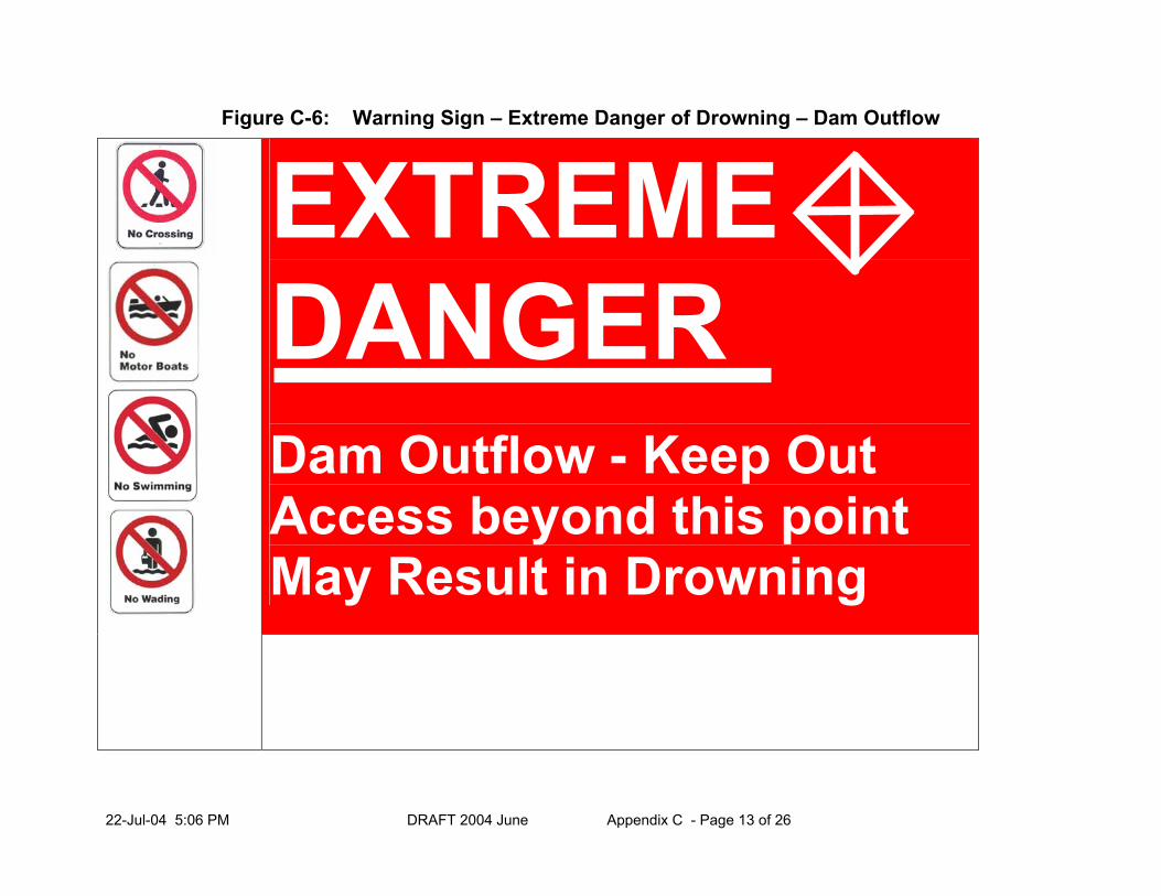
22-Jul-04 5:06 PM DRAFT 2004 June Appendix C - Page 13 of 26
Figure C-6: Warning Sign – Extreme Danger of Drowning – Dam Outflow
EXTREME DANGER
Dam Outflow - Keep Out Access beyond this point May Result in Drowning

22-Jul-04 5:06 PM DRAFT 2004 June Appendix C - Page 14 of 26
Figure C-7: Warning Sign – Riverbed Floods
EXTREME DANGER
Dam Upstream –Keep Away This Riverbed Floods Without Warning

22-Jul-04 5:06 PM DRAFT 2004 June Appendix C - Page 15 of 26
Figure C-8: Warning Sign – Swift Currents and Undertow
EXTREME DANGER
Keep Out – Swift Currents & Undertow May Occur At Anytime

22-Jul-04 5:06 PM DRAFT 2004 June Appendix C - Page 16 of 26
Figure C-9: Warning Sign – No Trespassing
DANGER
Dam- No Trespassing
Information Text Company Logo (Optional) (Optional)

22-Jul-04 5:06 PM DRAFT 2004 June Appendix C - Page 17 of 26
Figure C-10: Warning Sign – Dam Outflow
DANGER
Dam Outflow- Keep Out
Information Text Company Logo (Optional) (Optional)

22-Jul-04 5:06 PM DRAFT 2004 June Appendix C - Page 18 of 26
Figure C-11: Extreme Danger – No Trespassing
EXTREME DANGER
Dam- No Trespassing
Information Text Company Logo (Optional) (Optional)
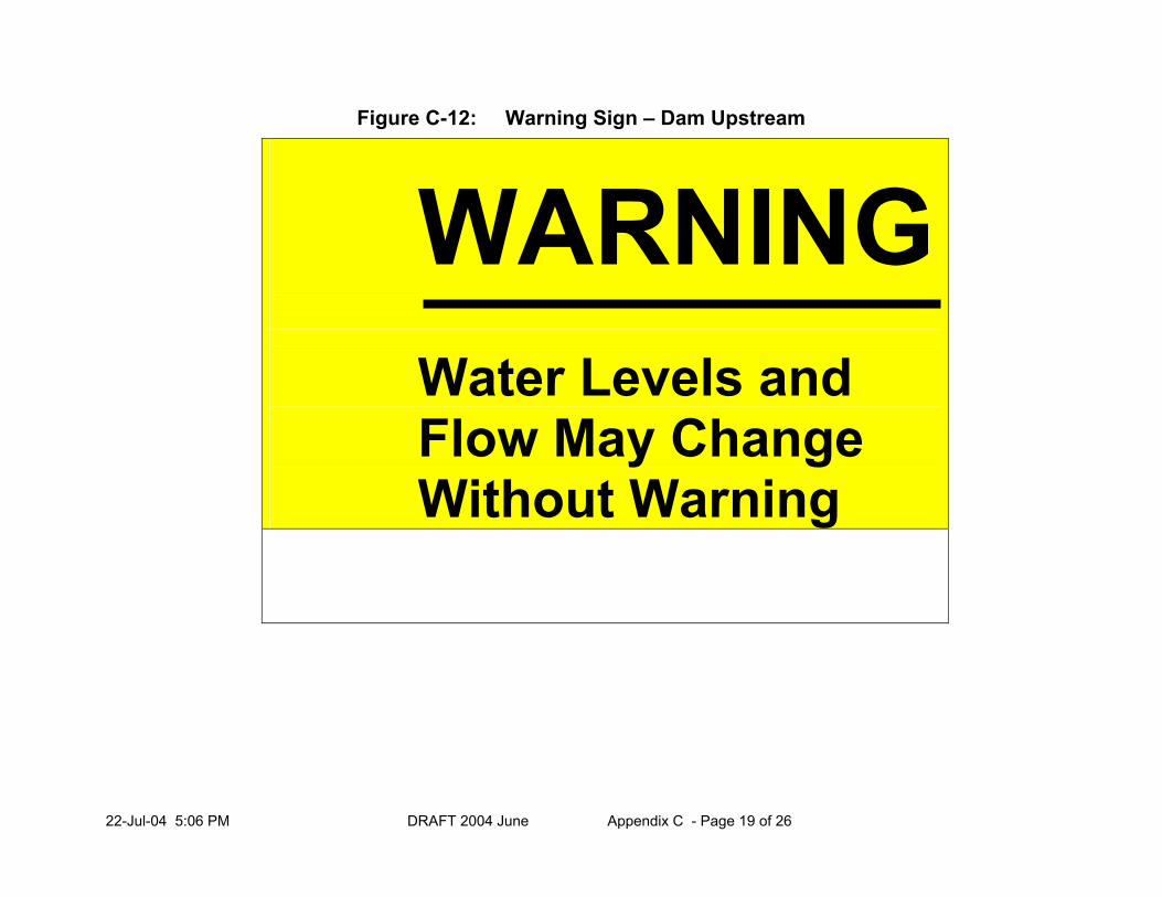
22-Jul-04 5:06 PM DRAFT 2004 June Appendix C - Page 19 of 26
Figure C-12: Warning Sign – Dam Upstream
WARNING
Water Levels and Flow May Change Without Warning

22-Jul-04 5:06 PM DRAFT 2004 June Appendix C - Page 20 of 26
Figure C-13: Symbols and Pictograms

22-Jul-04 5:06 PM DRAFT 2004 June Appendix C - Page 21 of 26
C-4.0 BEST MANAGEMENT PRACTICES FOR FENCING AND RAILINGS
C-4.1 General
In many instances, deterrents (in addition to signage) in the form of physical barriers will be required to restrict access to hazardous areas and to address public safety. Where the Public Safety Assessment has been completed in Section 5.5.4.3 and it has been determined that the general public may not recognize the severity of a given hazard, the Public Safety Measures BMP Plan should identify appropriate physical barriers, in addition to signs, that should be used to restrict access where access could lead to encounters with man-made hazards that are deemed as unsafe areas on and around dams.
1) Railings should, at a minimum, meet requirements consistent with those prescribed
under the Occupational Health and Safety Act (OHSA). 2) Railings and/or fencing and appropriate safety signage may be required, when public
access to a dam is desired (e.g., scenic lookouts or other recreational activity) or unavoidable (e.g., public roadways or pedestrian crossings) consistent with the Ontario Building Code.
3) Where the dam owner has determined to prohibit access to the hazard by land or
water as a result of the public safety assessment (outlined in Sections 5.5.4.3 and 5.5.4.4 of these BMP’s), and there is a high level of use and access by the public, railings and/or fencing should be used to restrict access to the hazardous area.
4) It is recommended that a minimum a 3 bar railing with horizontal bars should be used where
a vertical drop of 1 metre or more exists and where the dam is in an area with a low level of use and access by the public.
5) It is recommended that a minimum 1 metre high railing, with vertical bars spaced 4 inches
apart, should be used where a vertical drop of 1 metre or more exists and the dam is in an area with a high level of use and access by the public.
6) A chain link fence 2 metres in height may be required where it is likely that the general public
may not recognize the severity of a given hazard and where a vertical drop of 3 metres or more exists, and there is significant evidence of use by the public of the land and water at and surrounding the dam site.
7) Machinery and other potentially dangerous elements of dams should be contained
within a fenced area. 8) Areas along steep embankments located above vertical drops should be protected with
barricades or guard rails.

22-Jul-04 5:06 PM DRAFT 2004 June Appendix C - Page 22 of 26
C-5.0 SAFETY BOOMS AND BUOYS
C-5.1 General A safety boom is intended to perform the following functions:
1) provide a visual warning of a dangerous water zone;
2) promote self-rescue of stranded boaters and swimmers due to the orientation of the boom (booms should be located at a sufficient distance from the hazard, potentially providing a physical restraint device for stranded boaters or swimmers on the waterway);
3) act as a fence on water to minimize the risk of boaters entering a hazardous area; and
4) supplement the signage at the site.
5) Ideally, booms should be installed at an angle to the current so that a swimmer holding on to the cable will be pushed toward the shore. Tailrace barriers should be placed far enough downstream so that watercraft cannot approach too closely and be swamped when the facility begins operation. This is particularly true in areas where fishing tubes are popular.
6) Debris booms are not intended to function as safety booms and can present navigability problems due to visibility issues for boaters. Debris booms typically are not coloured and are designed to float low in the water to be effective in holding and/or directing floating debris to either bank for removal.
7) Debris booms, if oriented properly and at a sufficiently safe distance from the hazard, may be modified for use as a safety boom. This is accomplished by the installation of buoys or markers either immediately upstream or as part of the debris boom to warn boaters of the boom location. Site-specific conditions will govern the exact location of the safety booms and buoys.
8) All safety booms and buoys should meet municipal, provincial, and federal regulations for
installation and navigation. All booms and buoys on navigable watercourses should be registered with the appropriate regulatory agency to ensure that the boating public is aware of the locations (e.g., federal agencies, such as, the Canadian Coast Guard, Department of Fisheries and Oceans, and Environment Canada).

22-Jul-04 5:06 PM DRAFT 2004 June Appendix C - Page 23 of 26
C-5.2 Upstream Safety Booms and Buoys 1) Where the Hazard Identification has determined that the general public may not recognize the
severity of a given hazard, safety boom(s), in addition to signs, should be used to restrict access (entrance) to:
(a) hydropower water intake canals, where the intake canal has vertical or steep side slopes and currents would prevent egress; and
(b) overflow service spillways (not including emergency spillways) where: (i) there is significant level of use and access by the public of land and water at and
surrounding the dam site; or (ii) dams are close to areas designated for swimming/recreation.
2) Booms should also be considered for use upstream of sluice gates, stop-log spillways, and
other locations where there exists a potential for members of the public to access dangerous waters upstream of a dam.
C-5.3 Downstream Safety Booms and Buoys
1) Booms are preferable to buoys as they provide a continuous visual barrier; however, booms often have performance issues in turbulent flows associated with tailrace and discharge channels.
2) It is recommended that either safety booms or buoys be placed to establish a dangerous water zone downstream of sluice gates and generating station tailraces where there is a minimum water level retained year round for boating and the downstream area has a history of use by the public.
C-5.4 Installation, Removal and Storage of Booms 1) In the instances where safety booms and buoys are required and cannot be left in place year
round, they should be installed no later than May 15 and removed no earlier than October 15. 2) Booms should be secured and appropriately marked so as not to present a hazard to the
public. 3) Unusual ice conditions or other circumstances, such as high flows, may necessitate removal
or installation of the booms and buoys outside of the prescribed dates in 8.4.1. In these instances the installation or removal should be done as expeditiously as possible.
4) When installing and removing booms, procedures should be reviewed to ensure that hazards
are not presented to the public.

22-Jul-04 5:06 PM DRAFT 2004 June Appendix C - Page 24 of 26
C-6.0 BEST MANAGEMENT PRACTICES FOR ILLUMINATION
1) Lighting should be considered at dams and appurtenances to provide for night visibility, particularly if boating at night is a regular activity in that area.
2) Lights may be used to illuminate signs, the dam itself, and potentially hazardous areas. Signs with reflective paint should be considered so that safety devices are effective under adverse weather conditions.
3) In areas of heavy use, lighting also may reduce vandalism, thereby enhancing public safety. C-7.0 BEST MANAGEMENT PRACTICES FOR SIRENS, WARNING
LIGHTS, AND SURVEILLANCE CAMERAS
C-7.1 General
In areas where it is not practical to provide sufficient physical barriers to eliminate public access to hazardous areas, particularly automatic or remote controlled sluices, alternative forms of warning are to be considered such as sirens and warning lights.
1) Wherever sirens or warning lights are used, signs may be used to inform the public of the meaning of the alerts.
2) Where video surveillance cameras are installed as a part of these Standards, signs may be used to inform the public of the presence of the surveillance.
C-7.2 Best Management Practices for Audible Warning Devices (Sirens)
and Warning Lights
1) Where the Hazard Identification has determined that hazards cannot be eliminated or where access by the public cannot be restricted by means of physical barriers (i.e., fences and booms), and the general public may not recognize the severity of a potential hazard, sirens, in addition to signs, should be installed based on the following criteria:
(a) Dams that measure more than 7.5 metres of height and that have a reservoir storage capacity of more than 100,000 cubic metres, where those dams have discharge facilities from which the release of water creates an increase in the flow velocity and/or rate of rise of water level in any portion of the downstream channel that could result in serious injury, drowning, or other accidental death; and
(b) Dams that have remotely and/or automatically operated sluice gates or have powerhouse tailraces and where the operator cannot clearly view the entire tailwater area to ensure that no person(s) are at risk prior to operating the discharge facilities from which the release of water creates an increase in the flow velocity and/or rate of rise of water level in any portion of the downstream channel that could result in serious injury, drowning, or other accidental death.
2) The sequence of sounding a siren should be designed in the control logic for the sluice gate opening. The timing and duration of the audible alert and lapse period prior to opening and subsequent operation of discharge facilities should be sufficient to provide the public adequate time to egress the hazard area. This is especially critical where a water flow

22-Jul-04 5:06 PM DRAFT 2004 June Appendix C - Page 25 of 26
velocity and/or rate of rise of water level is created that could result in serious injury, drowning,or other accidental death.
3) The audible warning signal should have a designated signal reception area in which persons are intended to recognize and react to a warning signal.
4) An audible warning signal is defined as that which marks the onset and, if necessary, the duration and the end of a hazardous situation.
5) The siren may emit a signal that is clearly audible where the minimum level is 65dB(A) or 15dB(A) above all other background noise (whichever is greater), convey a level of urgency, and be unlike any other audible signals used at the facility within the signal reception area.
6) The location / audible rating of the siren should not allow any member of the public to be exposed to 115dB(A) or higher.
7) In all applications, the siren may be effective in alerting the public of changing water level and flow conditions for the full length of the hazard in the downstream channel which may require multiple warning devices connected in series:
(a) The system, as designed, requires a level of redundancy consistent with the hazard;
(b) The design of the system should include contingency plans in the event that the siren is out of service; and
(c) As identified in Section C-3.2.6, item 3), signage should be used accordingly.
8) The threshold in terms of increased flow velocity and/or rate of rise of water level in any portion of the downstream channel that could result in serious injury, drowning, or other accidental death is where:
a) an increase in the flow velocity exceeds 0.5 metres per second in any 15 minute period; and/or
b) an increased rate of rise of water level exceeds 0.5 metres in any 15 minute period.
The above threshold concepts are derived from Natural Hazards Technical Guides: Provincial Policy Statement (2002) for safe access and egress across a hazardous area.
9) A sudden stepwise increase up to the maximum permissible, as identified in the threshold, is more dangerous than a uniform increase.
10) In some instances it may not be acceptable to use sirens due to the proximity of the public and the frequency of gate operation. In this instance, alternatives such as warning lights may be used for alerting the public.
11) The steady state of background ambient noise associated with spilling water requires the audible warning signal to be a sweeping signal (i.e., a sliding change in frequency). Given this requirement, the standard Slow Whoop signal is recommended for use on water conveyance structures.
12) Audible warning signals are not to be confused with an audible emergency evacuation signal. The audible emergency evacuation signal is a specific temporal three pattern (T3) which is defined under its own ISO Standard 8201. The audible emergency evacuation signal (T3) has

22-Jul-04 5:06 PM DRAFT 2004 June Appendix C - Page 26 of 26
been reserved in Canada by the National Building Code for building fire alarms and should not be used.
13) An audible warning signal can have the following optional characteristics.
Character available for ON phase Temporal pattern
• Sweeping
• Bursts
• Alternating pitch (two or three frequency steps)
Note: Urgency can be implied by rapid rhythm, dissonance, or high pitch.
• Continuous or alternating ON/OFF
• Alternating ON/OFF
• Continuous alternating ON/OFF
C-7.3 Best Management Practices for Surveillance Cameras (i.e., Video
Surveillance)
It is possible that the public whose private property is adjacent to the facilities may deem sirens an annoyance.
1) In conjunction with audible warning devices (sirens) and warning lights, particularly in locations where there is an absence of on-site observations, video surveillance may be installed and used during the following applications:
a) prior to unit start-up at hydro-electric generation stations;
b) sluice gate openings; and
c) at all powerhouse tailraces where the operation has the potential to cause loss of life (i.e., the release of water is in excess of that prescribed in the Standards).
2) Video surveillance cameras may be an acceptable daytime public safety device, provided that full surveillance of the hazardous area in the downstream channel is achievable prior to releasing water from the reservoir or unit start-up.
3) In the case of video camera surveillance, once the operating controller determines that there is no person(s) at risk within the field of view of the camera, then the sluice gate may be opened or the generator started according to prescribed procedures.
Information on public safety measures is available from a variety of sources including:
• Federal Energy Regulatory Commission of the U.S.A. (FERC); Safety Signage at Hydropower Projects, October 2001 Internet Site: http://www.ferc.gov/hydro/safety/site/report/safety_signage.htm
• Ontario Power Generation (OPG); Guidelines for Waterways Public Safety, January 2003
• U.S. Army Corps of Engineers Sign Manual. Internet Site: http://www.mvp.usace.army.mil/mcx/sign_standards_prog

Lakes and Rivers Improvement Act Technical Guidelines – Criteria & Standards for Approval
APPENDIX D: GLOSSARY OF TERMS Abutment: The end of a dam, or other structure, consisting of a wall or natural formation. An abutment wall is similar to a wing wall.
Active Pressure: The horizontal push from earth on a retaining wall.
Anti-Seepage Collars: Plates that are placed around a structure, such as a pipe, in a watertight manner to force any seepage water to travel around the pipe thereby lengthening the flow path and reducing the amount of seepage.
Anti-Vortex Device: A device, such as a baffle plate, that prevents the swirling action of water at an inlet to a spillway thereby increasing the capacity of the inlet.
Apron: A hard surface on the bed of a stream to prevent scour. An apron may be made of concrete, riprap, or other materials. An apron can also refer to a layer of impervious material placed in front of a dam.
Arterial Road: A main road to carry traffic from one centre to another.
Backfill Material: Earth or other material used to replace material removed during construction.
Backwater: The curve of the raised water surface resulting from the construction of a dam.
Baffles (In Culverts): Steel plates or concrete blocks anchored inside a culvert to break up flow in the lower portion of the culvert allowing fish to swim through the culvert.
Bedload: Sediment moving along the streambed.
Bioengineering: Using natural living materials for bank stabilization, erosion control, and habitat creation, for example, willow plantings, brush layering, or transplanted trees.
Borehole: A hole driven into the ground to obtain information about the soil’s stratum and to obtain samples for testing.
Borings: A hole made in soil or rock used in connection with boreholes for soil testing.
Borrow Area: An area containing a pit for obtaining earth for the construction of a dam or embankment.
Bottom Draw-Off: A draw, usually a pipe, placed well below the surface of the water to take cooler water from a lower elevation of the reservoir.
By-pass Ponds: A partial diversion of stream flow from a river or stream whereby the diverted water is passed through a pond. The pond may be excavated or formed by embankments.
Channelization: Altering the alignment, width, depth, sinuosity, conveyance, or bed or bank material of a river or stream channel.
Coldwater Streams: Streams that support coldwater species such as trout. The maximum temperature of such a stream should not exceed 20 degrees.
Collector Road: A road that serves to connect local roads to main routes (arterial roads).
Compensation: The creation of new habitat or the enhancement of existing habitat to replace habitat loss as a result of the undertaking. Compensation, by definition, implies loss or damage to habitat and should only be considered when mitigation is not possible or inadequate.
Culvert: A conduit for carrying water through an embankment.
Cut-off Wall: A wall intended to prevent seepage or undermining.

22-Jul-04 5:06 PM DRAFT 2004 June Appendix D - Page 2 of 6
Cut-off Trench: A trench filled with impervious soil, such as clay, to prevent seepage of water under a dam.
Denil Fishway: A fishway consisting of a flume containing closely spaced baffles intended to break up the flow in the lower part of the fishway and create a swimming path for fish. Denil baffles usually consist of steel plates with large notches.
Design Flood: The maximum flow in a stream or river that a dam is designed to pass safely.
Design Life: The length of time for which it is economically sound to require a structure to serve without major repairs.
Dynamic Equilibrium: Refers to an open system in a steady state in which there is continuous inflow of materials but within which the form of character of the system remains unchanged. Within dynamic equilibrium, the channel exhibits patterns of erosion and deposition, but there is no net change in input or output of materials. The state is stable but features may change over time.
Embankment: A bank of earth or rock constructed above the normal ground surface.
Emergency Spillway: The spillway that is designed to carry extraordinary flows such as the design flood.
Energy Dissipation Structure: A stilling basin structure, often containing baffle blocks, intended to cause turbulence and break up the flow energy resulting from discharge from a dam.
Factor of Safety: The maximum resisting forces divided by the maximum loading forces.
Fetch: The free distance wind can drive across a lake or reservoir.
Filter Cloth: A filter constructed of cloth type material, also known as geotextile.
Filter: A granular material placed to facilitate drainage and at the same time strain or prevent the admission of fine soils. A filter may also be constructed of a cloth-type material (geotextile).
Fish Habitat: Spawning grounds, nursery, rearing, food supply, and migration areas on which fish depend directly or indirectly in order to carry out their life processes (Department of Fisheries and Oceans definition).
Fish: Includes shellfish, crustaceans, marine animals, and the eggs, sperm, spawn, spat, larvae, and juvenile life stages of fish, shellfish, crustaceans, and marine mammals (based on the Department of Fisheries And Oceans definition).
Fishway: A combination of structural and/or non-structural conditions, including biological and chemical, which accomplish the safe passage of fish upstream and/or downstream past obstructions in the river.
Fluvial Geomorphology: The study of river processes and resulting channel patterns.
Footing: That portion of the structure, usually below ground, that distributes the pressure to the soil.
Foundation: The soil or rock upon which the structure or embankment rests. An alternative definition is similar to footing.
Frazil Ice: Also known as slush ice is formed by agitated water in rapids during cold spells. Frazil develops when water is super cooled (cooled below freezing) but solid ice is prevented by fast flowing agitated water; instead ice crystals form to create an ice crystal blizzard. When the ice crystals reach calmer water, they rapidly bind together to form large ice masses.

22-Jul-04 5:06 PM DRAFT 2004 June Appendix D - Page 3 of 6
Freeboard: The distance from normal maximum water level (i.e., full supply operating level) to the crest of a dam that provides for wave action without overflow. Also used with other structures, e.g., the distance from the maximum water level to the underside of a bridge.
Freeway: A main arterial road designed to a high standard with limited access.
Frost Line: The line or distance below ground to which frost will penetrate.
Geotextile: A filter constructed of cloth type material.
Gravity Spillway: The spillway of a dam that sustains a head of water and resists overturning and sliding by virtue of its own weight.
Groundwater: Sub-surface water or water stored in the pores, cracks, and crevices in the ground below the water table.
Grout Curtains: A row of holes drilled into rock beneath a dam filled with cement or chemical grout to seal the fissures in the rock.
Hardening Channels: The process of adding materials such as stone or concrete to the bed or banks of a stream to prevent erosion.
Harmful Alteration: Any changes that adversely affect the abilities of the physical habitat to provide the basic life requirements can be considered harmful (Federal Fisheries Act definition).
Head: The height of water above a point of reference (also the potential energy of water above a point of reference).
Headwater: The water upstream (sometimes the depth of water upstream). Alternative usage is the source of a stream.
Heat Loop: A loop of pipe extending from a building into a body of water for the purpose of transferring heat from the water to the building.
Hydraulic Capacity: The maximum flow that a dam, spillway, or other structure can safely pass.
Hydraulic: Relating to the flow of liquids particularly water.
Hydrograph: The relationship between time and flow, or time and water level, often illustrated on a graph.
Hydrology: The study of water.
Hypolimnion: The deep, cold stratum of water that is undisturbed and oxygen deficient. Cold bottom waters are typical summer holding habitats for coldwater fish species, such as, lake trout, whitefish, and lake herring (cisco). Hypolimnia is the plural of hypolimnion.
Impervious Core: The central portion of an earth dam made of an impervious material, such as clay, to prevent excessive seepage.
Inflow Design Flood: The maximum flood entering a reservoir for which the dam and reservoir are designed.
Invertebrates: Animals that do not possess a backbone (i.e., insects, clams, crayfish).
Local Road: A road to residences, farms, and buildings not used as a main route.
Lock: A chamber separating two reaches of a river or canal at different elevations. Locks are intended for the passage of boats.
Mitigation: Actions taken during project planning, design, construction, or operation to alleviate adverse effects on habitat.

22-Jul-04 5:06 PM DRAFT 2004 June Appendix D - Page 4 of 6
Net Gain (of fish habitat): An increase in the area and/or number of fish habitats through creation of new fish habitat areas or the expansion of and/or rehabilitation of existing fish habitat areas.
No Net Loss (of fish habitat): No loss of fish habitat through no change or habitat replacement. Net loss is reviewed on a project-by-project basis so that further reductions to Ontario’s fisheries resources may be prevented.
Oligotrophic: Trophic state of a waterbody characterized by low amounts of inorganic and organic nutrients and low biological rates; used in reference to lakes with low nutrient supply relative to the volume of water they contain. The lakes are generally deep (>15m mean depth) and clear with high concentrations of dissolved oxygen in hypolimnion.
Passive Pressure: The resistance of a vertical earth face to deformation by a horizontal force.
Piezometer: A measuring tube device for water pressure.
Piping: The movement through a dam of water and soil. Uncontrolled piping can lead to serious internal erosion and failure.
Pool and Riffle: Deeper section and shallower section of a stream forming an undulating series.
Pool and Weir Fishway: A fishway consisting of a series of pools separated by baffle weirs over which fish jump.
Probable Maximum Flood (PMF): The largest possible flood based on an analysis of the maximum possible precipitation in a given area.
Productive Capacity: The maximum natural capability of habitats to produce healthy fish or to support or produce aquatic organisms upon which fish depend.
Reach: A length of stream.
Regional Flood: A specified flood on a watershed for various regions in Ontario or the 1:100 year flood, whichever is the greater.
Regulatory Flood: The flood used in Ontario for the purpose of regulating land development.
Relief Drains: Drains constructed in a dam to relieve pore-water pressure.
Retaining Wall: A wall built to hold back earth along a river.
Return Period Flood: The flood that will be equaled or exceeded once during the specified period.
Revetments: A wall or facing of stone, or concrete, or other materials placed on a stream bank to prevent erosion.
Riffle: Shallow section of a stream often comprised of gravel bars.
Rigid Structures: A structure with little or no flex under load, e.g., reinforced concrete wall.
Riparian Vegetation: Vegetation that grows on land beside a stream, creek, or river.
Riparian: Adjacent to a river or lake.
Riprap: Rough stone of various sizes placed compactly or irregularly to prevent scour by water or debris.
Routing: The reduction in the peak of a flood by using the storage of a section of stream or reservoir.
Salmonoid: Relating to various salmon or trout fish species.
Sedimentation: The process by which particles of material, usually soil, fall into the water. Particles may cause turbidity and also settle. The rate of settlement depends on the particle size.

22-Jul-04 5:06 PM DRAFT 2004 June Appendix D - Page 5 of 6
Sheet Piling: Closely set piles of timber or, more commonly, steel driven vertically into the ground to keep out water or earth. Steel sheet piling is manufactured to be interlocked.
Shell: The outer layers of a dam constructed of erosion-resistant material and good draining soils such as course sand and gravel.
Siltation: Similar to sedimentation but refers to fine particle sizes but not as fine as clays (from 0.002 - 0.06 mm).
Sinuosity: The meandering pattern of a stream or river (wavy form).
Spillway Design Flood: The maximum amount of water for which the spillway(s) of a dam is designed. Spillway Design Flood is less than the Inflow Design Flood if reservoir routing is used.
Spillway: A passage serving a dam through which water may be discharged.
Stage: The water level measured from a chosen reference line.
Stage Discharge: The relationship between stage and flow.
Stage Storage: The relationship between stage and water held in storage for a reservoir or reach of river.
Standard Proctor Density: A standard laboratory test for compacting soils. Optimum compaction is obtained with a certain moisture content. Various moisture contents are tested and the maximum dry density obtained.
Stilling Basin: A basin at the end of a dam containing a pool to dampen the flow energy resulting from discharge from the dam.
Stop Logs: A beam, usually of timber, that fits between vertical grooves in walls or piers to close a spillway. The stop logs are laid horizontally one on top of the other.
Tailings Dam: A dam constructed of mine waste material intended to impound an area for the capture of additional mine waste and process water.
Tailwater: The downstream water (sometimes the downstream water depth).
Test Pits: A trial excavation used to study the soil stratums and take soil samples.
Trash Rack: Parallel bars or a screen protecting a spillway intake from floating debris.
Travel Time: The time taken by water to flow through a section of stream, usually determined under maximum flow.
Unified Classification System: This system takes into account the engineering properties of soils, is descriptive, and is easily associated with actual soils. Soils can readily be classified by visual and manual examination without the necessity of laboratory tests. The system is based on the size of soil particles, their distribution, and the characteristics of very fine-grained particles.
Unit Weights: The density of a material.
Upwelling: Areas on a stream’s banks or bed containing springs releasing groundwater into the stream.
Vertical Slot Fishway: A fishway consisting of a flume with pools separated by baffles. The baffles contain vertical slots through which fish burst to make a rapid move from one resting pool to the other.
Water Crossing: A bridge, culvert or causeway that is constructed to provide access between two places separated by water but that also holds back, forwards, or diverts water.
Waterpower: Water used for hydroelectric purposes.

22-Jul-04 5:06 PM DRAFT 2004 June Appendix D - Page 6 of 6
Wetlands: An area that is connected to, or considered part of, a river or lake where shallow flooding occurs, either periodically or permanently. A wetland contains hydrophytic or water-tolerant plants typical of shallow flooding.
Wing Walls: A wall along the side of a spillway (or other structure) that extends beyond the spillway to retain earth.

Lakes and Rivers Improvement Act Technical Guidelines – Criteria & Standards for Approval
APPENDIX E: REFERENCES AND ADDITIONAL SOURCES OF INFORMATION Design Floods Bruce, J. P. 1965. Preliminary estimates of probable maximum precipitation over Southern
Ontario. Department of Planning, Ontario. Moin, S. M. A, and M. A. Shaw. 1985. Regional flood frequency for Ontario streams, vol. 1- 3.
Canada /Ontario Flood Damage Reduction Program, Inland Waters Directorate, Environment Canada, Burlington, Ontario.
Ontario Government. 1996. Provincial policy statement. Queens Printer, Ontario. Ontario Ministry of Natural Resources. 1988. Floodplain management in Ontario technical
guidelines. Ontario Ministry of Natural Resources, Ontario. Ontario Ministry of Natural Resources. 1997. Natural hazards training manual, Provincial policy
statement, public health and safety policies 3.1, version 1.0. Ontario Ministry of Natural Resources, Peterborough, Ontario.
Ontario Ministry of Transportation. 1980-1988. MTO drainage manual, chapter B and chapter H
Ontario Ministry of Transportation, Downsview, Ontario. U.S. Department of Agriculture. 1972. S.C.S. national engineering handbook, section 4.
Hydrology Soil Conservation Service, United States Government Printing Office, Washington, D.C.
United States Department of the Interior, Bureau of Reclamation, 1974. Design of small dams, a
water resources technical publication, United States Government Printing Office, Washington, D.C.
Weather Bureau. 1961. Rainfall frequency atlas of the United States for durations of 30 minutes
to 24-hours and return periods from 1 to 100 years, technical paper No. 40. United States Government Printing Office, Washington, D.C.
World Meteorological Organization. 1974. Guide to hydrological practice, WMO No.168, World Meteorological Organization, Geneva. Natural Resources References Department of Fisheries and Oceans, Canada 1993. Habitat conservation guidelines developed
from the policy for the management of fish habitat (1986). Department of Fisheries and Oceans, Canada, Ottawa, Ontario.
Department of Fisheries and Oceans, Canada. 1986. Policy for the management of fish habitat
Department of Fisheries and Oceans, Canada, Ottawa, Ontario.

22-Jul-04 5:06 PM DRAFT 2004 June Appendix E - Page 2 of 4
Department of Fisheries and Oceans, Canada. 1987. Canada’s fish habitat law. Information and Publications Branch, Communications Directorate, Department of Fisheries and Oceans, Canada, Ottawa, Ontario.
Kerr, S. J. 1993. A bibliography of selected fish habitat protection guidelines and references
(volume 1, aquatic habitat, volume 2, impacts of activities on aquatic habitat in Ontario). Ontario Ministry of Natural Resources, Peterborough, Ontario.
Kerr, S. J. 1993. A summary of policies and guidelines for the protection of fish habitat in
Ontario. Ontario Ministry of Natural Resources, Peterborough, Ontario. Kerr, S. J. and H. J. Rietveld. 1994. Aquatic habitat mitigation and compensation reference
manual. Watershed, Shorelines and Habitat Section, Aquatic Ecosystems Branch, Ontario Ministry of Natural Resources, Peterborough, Ontario.
Leopold, L. B., M. G. Wolman, and J. P. Miller. 1964. Fluvial processes in geomorphology. W.
H. Freeman. Ontario Ministry of Natural Resources and Ontario Ministry of Municipal Affairs. 1992. Manual
of implementation guidelines for the wetlands policy statement. Queens Printer, Ontario. Ontario Ministry of Natural Resources. (in writing). The wetlands evaluation system, 3rd edition,
technical manual for natural heritage under planning policy. Ontario Ministry of Natural Resources, Toronto, Ontario.
Ontario Ministry of Natural Resources. 1986. Waterpower program guidelines. Ontario Ministry
of Natural Resources, Toronto. Ontario Ministry of Natural Resources. 1994. Fish habitat guidelines for developing areas.
Ontario Ministry of Natural Resources, Aquatic Ecosystems Branch, Peterborough, Ontario. Ontario Ministry of Natural Resources. 1994. Natural channel systems: an approach to
management and design. Queens Printer, Ontario. Ontario Ministry of Natural Resources. 1997. Natural heritage training manual for policy 2.3 of
the provincial policy statement. Ontario Ministry of Natural Resources, Land Use Planning Branch, Peterborough, Ontario.
Ontario Ministry of Natural Resources. 1997. Standards for fish habitat classification and
mapping in Ontario, interim. Ontario Ministry of Natural Resources, Fish and Wildlife Branch, Peterborough, Ontario.
Ontario Provincial Policy Statement. 1996. Provincial policy statement, issued under section 3 of
the Planning Act, Order in Council 764-96 and 102-97. Queens Printer, Ontario. Rosgen, D. L. 1994. A classification of natural rivers. Catena 22: 169-199.

22-Jul-04 5:06 PM DRAFT 2004 June Appendix E - Page 3 of 4
Riparian Interests Ontario Government. 1996. Provincial policy statement. Queens Printer, Ontario.
Ontario Ministry of Natural Resources and Ontario Ministry of Municipal Affairs. 1988. The provincial floodplain planning policy statement and associated implementation guidelines. Queens Printer, Ontario.
Ontario Ministry of Natural Resources. 1988. Floodplain management in Ontario technical
guidelines. Ontario Ministry of Natural Resources, Toronto. Ontario Ministry of Natural Resources. 1997. Natural hazards training manual, Provincial policy
statement, public health and safety policies 3.1, version 1.0. Ontario Ministry of Natural Resources, Peterborough, Ontario.
Technical References Canadian Dam Safety Association. 1995. Dam safety guidelines. Canadian Dam Safety
Association, Edmonton, Alberta. Clay, C. H. 1994 (2nd edition). Design of fishways and other fish facilities. Lewis Publishers,
Boca Raton, Florida. D’Eon, R. G, R. Lapointe, N. Bosnick, J. C. Davies, R. McLean, W. E. Watt, and R. G Wilson.
1995. The Beaver handbook: a guide to understanding and coping with beaver activity. Ontario Ministry of Natural Resources, Northeast Science and Technology, Timmins, Ontario.
Dane, B. G. 1978. A review and resolution of fish passage problems at culvert sites in British
Columbia, Fisheries and Marine Services Tech. Rep. No 810, British Columbia Ministry of Environment, Victoria, British Columbia.
Ontario Government. 1996. Provincial policy statement. Queens Printer, Ontario. Ontario Ministry of Natural Resources. 1988. Environmental Guidelines for Access Roads and
Water Crossings. Ontario Ministry of Natural Resources, Toronto. Ontario Ministry of Natural Resources. 1997. Natural hazards training manual, Provincial policy
statement, public health and safety policies 3.1, version 1.0. Ontario Ministry of Natural Resources, Peterborough, Ontario.
Ontario Ministry of Natural Resources. Floodplain management in Ontario Technical Guidelines.
Ontario Ministry of Natural Resources, Ontario.
Ontario Ministry of Northern Affairs and Mines. (in writing). The Mine Rehabilitation Code of Ontario. Queens Printer, Toronto.
United States Department of the Interior, Bureau of Reclamation. 1987 (3rd edition). Design of
small dams, a water resources technical publication, United States Government Printing Office, Washington, D.C.

22-Jul-04 5:06 PM DRAFT 2004 June Appendix E - Page 4 of 4
United States Department of the Interior, Bureau of Reclamation. 1983. Safety evaluation of existing dams, a manual for the safety evaluation of existing embankments and concrete dams, a water resources technical publication, United States Government Printing Office, Washington, D.C.
Wilson, R. G. 1994. CSP culvert installation at water crossings on forest access roads. Ontario
Ministry of Natural Resources, Northeast Science and Technology, Timmins, Ontario. Sediment / Erosion Control References Adamson, B. 1993 Generic sediment control plans for TransCanada pipeline water
crossings. Ontario Ministry of Natural Resources, Thunder Bay, Ontario. Adamson, B., and A. Harris. 1992. Sediment control plans: reducing sediment concerns
at water crossings, technical note, TN-20. Ontario Ministry of Natural Resources, Northwest Region Science and Technology Unit, Thunder Bay, Ontario.
Goldman, S. J., K. Jackson, and T. A. Bursztynsky. 1986. Erosion and sediment control
handbook. McGraw Hill, New York. Ontario Ministry of Environment and Energy. 1996 Erosion and sediment control on
construction sites, (draft April 1996). Ontario Ministry of Environment and Energy, Toronto.
Ontario Ministry of Natural Resources and others. 1987. Guidelines on erosion and
sediment control for urban construction sites. Ontario Ministry of Natural Resources, Toronto.
Ontario Ministry of Natural Resources and Trow Consulting Engineers Ltd. 1996.
Instream sediment control, field implementation manual. Ontario Ministry of Natural Resources, Northeast Region Science and Technology Unit, Timmins, Ontario.
Ontario Ministry of Natural Resources. 1988. Environmental Guidelines for Access
Roads and Water Crossings. Ontario Ministry of Natural Resources, Toronto. Ontario Ministry of Natural Resources. 1997. Natural hazards training manual, Provincial policy
statement, public health and safety policies 3.1, version 1.0. Ontario Ministry of Natural Resources, Peterborough, Ontario.
Ontario Ministry of Transportation. 1980 - 1988. Drainage manual, chapter F (vol. 2) -
erosion control. Ontario Ministry of Transportation, Downsview, Ontario.