journal of engineering transient responses of beam with...
TRANSCRIPT

International Journal of Engineering and Technology Volume 1 No. 2, November, 2011
137
Copyright IJET © 2011 - IJET Publications UK
Transient Responses of Beam with Elastic Foundation Supports under
Moving Wave Load Excitation
1Yi Wang,
2Yong Wang,
3 Biaobiao Zhang,
4Steve Shepard
1,2The Enjoyor Company,No.2, Xiyuan 8th Rd, Hangzhou City,
Zhejiang Province, 310030, P.R.China 3,4
Department of Mechanical Engineering, University of Alabama, Tuscaloosa,
AL35487,USA
ABSTRACT
In this paper, the responses of a free to free boundary constrained beam on elastic foundation to various moving loads are
studied by the application of finite element method. We apply the Newmark integration method for numerical simulation.
Results are verified by using commercial ANSYS package through modeling the beam with elastic foundation supports excited
by moving point load at the constant speed. The effects of the following parameters on the dynamic behavior of the beam
under both moving point load and pressure wave load are evaluated: the traveling speed of load, stiffness of the elastic
foundation base and viscous damping. This study offers a good basis for research work on the beam under moving acoustic
wave loads in the future.
Key words: Free to free beam, Elastic Foundation, Moving loads.
1. INTRODUCTION
Beam structures with elastic foundation supports
are widely used in many areas, such as mechanical and
aerospace engineering, long historical research work in
them can be seen in the literature of engineering
mechanics. Most of these beam problems focused on beam
issues subjected to time and space varying loads. Moving
loads have considerable effects on the dynamic behavior
of the structures. In order to make a better understanding
of dynamic responses from moving loads on beam
structure, it is necessary for us to review previous papers
in the literature. Olsson [1] studied the dynamics of a
simple supported beam subjected to the point load moving
at a constant speed by using both analytical and the finite
element method. Jaiswal and Iyengar [2] studied the
dynamics of the infinite beam on a finite elastic foundation
base subjected to a moving load. Effects of various
parameters, such as foundation mass, velocity of the
moving load, damping and axial force on the beam are
investigated. Thambiratnam and Zhuge[3]analyzed the
dynamic analysis of beams on an elastic foundation
subjected to moving point loads through simplifying the
foundation with springs of variable stiffness. Effects of
some parameters such as the speed of the moving load, the
foundation stiffness and the length of the beam on the
response of the beam were investigated. Chen et al. [4]
studied the response of an infinite Timoshenko beam on a
viscoelastic foundation under a harmonic moving load.
Kim and Roesset [5] analyzed dynamic response of an
infinitely long beam on the frequency-independent linear
hysteretic damping foundation base by using the constant
amplitude or a harmonic moving load as an excitation
force. In the model developed by Kim [6], the vibration
and stability of an infinite Euler - Bernoulli beam on a
Winkler foundation were investigated through applying a
static axial force and a moving load with either constant or
harmonic amplitude variations to excite the system. Some
important results were obtained from the process of
changing relative parameters. Bogacz, etc.,[7] studied
dynamical problems caused by a distributed load which
was acting on a beam on an elastic foundation at a moving
velocity, The load was represented by the Heaviside
function(or its linear superposition) and by a moving load
harmonically distributed in space. Shi,etc.[8] established
the mathematic model which was used to describe the
issue about the elastic foundation beam with cantilevered
support excited by the moving load velocity, the transient
response under the moving load velocity was obtained.
Nayyeriamiri and Onyango[9] studied the problem of a
simply-supported beam on elastic foundation to repeated
moving concentrated loads by means of the Fourier sine
transformation method in order to obtain the analytical
forced responses.
The objective of this paper is to develop a
numerical procedure for evaluating the dynamic response
of the elastic foundation beam when subjected to
sinusoidal moving loads. The finite element method is
used for modeling beam elements. We use the Newmark
integration method to obtain the dynamic response. Effects
of the following parameters on the dynamic behavior of
the beam are evaluated: the traveling speed of the load; the
stiffness of the elastic foundation base; viscous damping.
This will make a good basis for developing beam acoustic
sensor with the help of force reconstruction method which
is used to identify moving acoustic loads through their
excitation process on the beam structure.

International Journal of Engineering and Technology Volume 1 No. 2, November, 2011
138
Copyright IJET © 2011 - IJET Publications UK
2. THEORETICAL MODEL
Consider a finite-length Bernoulli – Euler beam
resting on an elastic foundation under moving sinusoidal
loads as illustrated in Fig. 1.
f(x,t)
The equation of motion is [10]
2 4
2 4
( , ) ( , ) ( , )2 ( , ) ( , )b f
W x t W x t W x tEI C W x t f x t
tt x
,
(1)
where the beam flexural rigidity is EI , the beam mass
density is , the foundation elasticity constant is fC , b
is the damping circular modal frequency, and ( , )f x t
represents moving loads. Note that the mass and bending
stiffness of the elastic foundation are being neglected. For
an elastically supported free to free end beam illustrated in
Fig.1 above, its boundary conditions are:
2 2
2 2
(0, ) ( , )0
W t W L t
t t
,
(2a) 3 3
3 3
(0, ) ( , )0
W t W L t
t t
.
(2b)
3. FE FORMULATION FOR THE BEAM
UNDER THE MOVING POINT LOAD
Generally the finite element analysis procedure is
to develop the model approximating the deformation
within an element through using nodal values of
displacement and rotation. Here it should be noted that the
energy contributions from each element depend on the
displacements and rotations at the nodes associated with
that element. By calculating the kinetic and strain energy
for each element, the contributions of each element will be
added together to obtain a global model of the structure.
The damping matrix is obtained through using the
dissipation function. The Euler-Bernoulli beam theory is
used for constituting the finite element matrices. The beam
illustrated in Fig.1 is modeled with 15 equally sized
elements. A straight beam element i with uniform cross
section under a moving point load is shown in Fig.2 as
following
Fig.2: Moving load on a straight beam element
A standard beam element is modeled using two
nodes (at the ends of the beam element), and two degrees
of freedom per node (translation and rotation), as shown in
Fig.2. The deformation within the ith element, ( , )W x t , is
approximated using cubic shape functions, the kinetic
energy and strain energy of a single element are:
2
0
( , ).
2
LA W x t
K E dxt
,
(3a) 2
2
2
0
( , ).
2
LEI W x t
S E dxx
.
(3b)
The shape functions of element i are represented as:
2 3
1
2 3
2
2 3
3
2 3
4
1 3 2
2
3 2
e
e e
e e e
e e
e
e e
e e e
e e
x xN
L L
x xN x L L
L L
x xN
L L
x xN L L
L L
.
(4)
Fig.1. Elastic foundation beam subjected to moving wave loads
Cf
x
c T
N=3 Beam
eL
x
E I ρA
Element i
2eW
2eW
1e
2e
F c
International Journal of Engineering and Technology Volume 1 No. 2, November, 2011
139
Copyright IJET © 2011 - IJET Publications UK
Mass matrix of this beam element is:
2 2
2 2
156 22 54 13
22 4 13 3
54 13 156 22420
13 3 22 4
e e
e e e ee
e e
e e e e
L L
L L L LALM
L L
L L L L
.
(5)
Stiffness matrix of the beam element is:
2 2
3
2 2
12 6 12 6
6 4 6 2
12 6 12 4
6 2 6 4
e e
e e e ee
e ee
e e e e
L L
L L L LELK
L LL
L L L L
.
(6)
Supposing that the beam structure is on the
Winkler's foundation base, the elastic foundation is
assumed to have constant linear spring modulus,
21 1 1
2 2 2
TT
foundation f f e f eU C W dA W C WdA d K d , (7)
in which the Winkler’s foundation stiffness matrix for the
element is:
T
f f e eK C N N dA .
(8)
Where matrix eN is shape function matrix
illustrated in the Eqn. (4), ed represents node
displacement vectors and dA is represented as Bdx ,
where B is the width of the beam face contact with the
foundation, so the foundation stiffness matrix is:
2 2
2 3 2 3
2 2
2 3 2 3
13 11 9 13
35 210 70 420
11 13
210 105 420 140
9 13 13 11
70 420 35 210
13 11
420 140 210 105
e f e f e f e f
e f e f e f e f
f
e f e f e f e f
e f e f e f e f
bL C bL C bL C bL C
bL C bL C bL C bL C
KbL C bL C bL C bL C
bL C bL C bL C bL C
. (9)
The expression of the beam element deflection is:
1 1 2 1 3 2 4 2( ) ( ) ( ) ( ) ( )e e e e e e e e eW x N x W N x N x W N x
, (10)
where ( )eiN x (i=1,2,3,4) are the interpolation functions
shown in Eqn. (4). After decouping equation (1) by using
equation (10), we get the equation of motion for a multiple
degree of freedom damped structural system is represented
as follows:
( )fM y C y K K y F t ,
(11)
where y , y and y are the respective acceleration,
velocity and displacement vectors for the whole structure
and ( )F t is the external force vector which is depended
on the moving point load. For the case that the moving
load is the pressure wave load rather than point load, the
problem will be more complicated, but the solution
procedure is similar.
4. RESULTS AND DISCUSSION
4.1 Moving point load at the constant speed
Table 1 provides a list of the initial modeling parameters,
including the geometry and material properties for both the
beam and elastic foundation. Here, E is the Young’s
modulus of beam material and FE is the Young’s
modulus of foundation material. The foundation elasticity
constant can be obtained from f F
BC E
H , where B is
width of the beam and h is the thickness of the foundation
base.
Table 1: Parameter Definition
The transverse point load F has a constant
velocityL
C
the beam and L is the total length of the beam. For the
Item Description Units Value
L Beam length M 0.5
B Beam width M 0.03
H Beam thickness M 0.001
c Moving load speed ms-1 343
ρ Beam density kgm-3 2700
E Beam young’s modulus Nm-2 70Gpa
μ Poisson’s ratio - 0.33
TH Foundation thickness m 1
EF Foundation Young’s
modulus
Nm-2 33.1MPa
International Journal of Engineering and Technology Volume 1 No. 2, November, 2011
140
Copyright IJET © 2011 - IJET Publications UK
forced vibration analysis, an implicit time integration
method named as the Newmark integration method [13] is
used with the integration parameters 1 4 and
1 2 , which lead to the constant-average acceleration
approximation. The time step is chosen as 20
20
Tt
during the beam transient response analysis to ensure that
all the 20 modes contribute to the dynamic response. Here
20T is the period of the 20th natural mode of the structure.
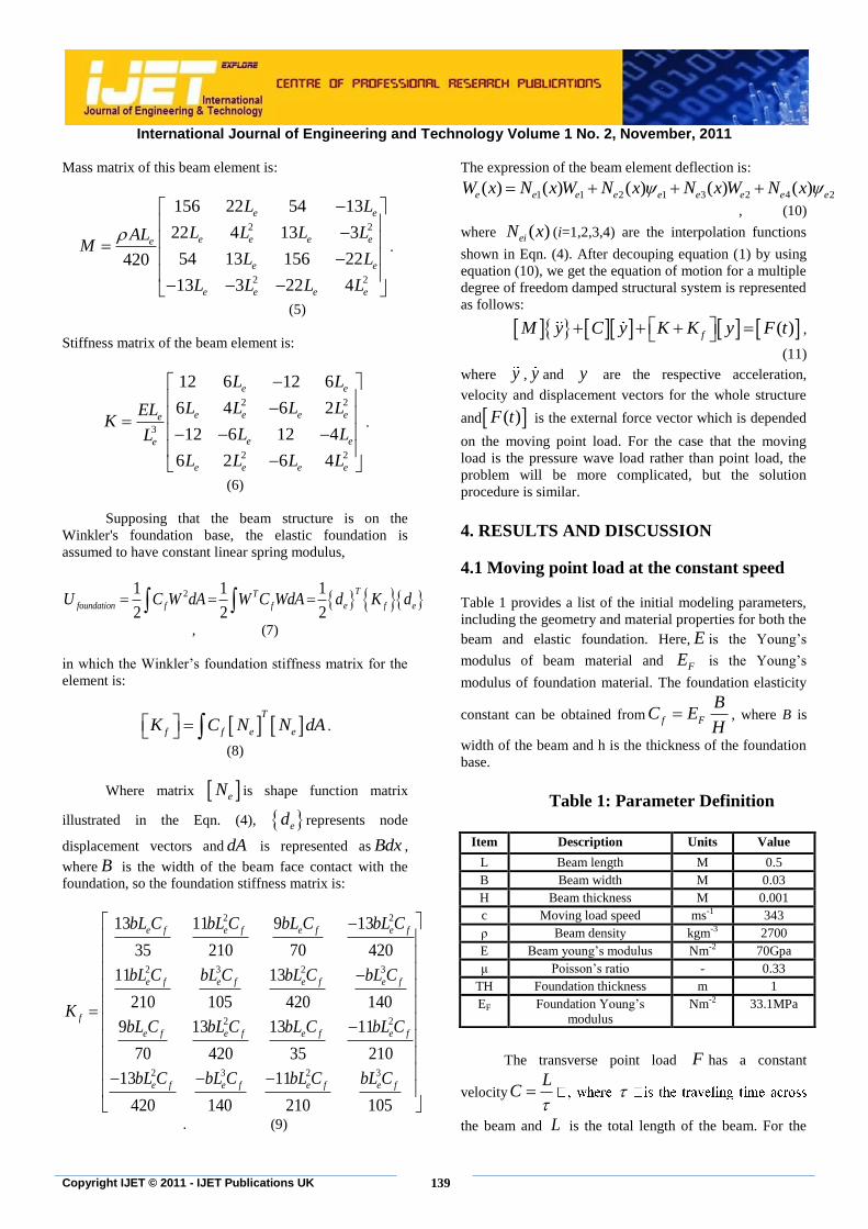
Responses of beam with elastic foundation under the
moving point load are obtained by using Matlab software
package and Ansys simulation results. As shown in Fig.3
and Fig.4, Matlab results show high agreement with Ansys
results.
Fig.3 Response of beam end point when the moving load is
leaving at 146m/s
Fig.4 Response of beam end point when the moving load is
leaving at 343m/s
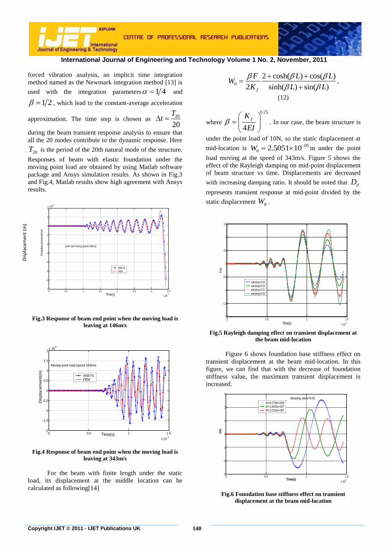
For the beam with finite length under the static
load, its displacement at the middle location can be
calculated as following[14]
0
2 cosh( ) cos( )
2 sinh( ) sin( )f
F L LW
K L L
,
(12)
where
0.25
4
fK
EI
. In our case, the beam structure is
under the point load of 10N, so the static displacement at
mid-location is 05
0 2.5051 10W m under the point
load moving at the speed of 343m/s. Figure 5 shows the
effect of the Rayleigh damping on mid-point displacement
of beam structure vs time. Displacements are decreased
with increasing damping ratio. It should be noted that dD
represents transient response at mid-point divided by the
static displacement 0W .
Fig.5 Rayleigh damping effect on transient displacement at
the beam mid-location
Figure 6 shows foundation base stiffness effect on
transient displacement at the beam mid-location. In this
figure, we can find that with the decrease of foundation
stiffness value, the maximum transient displacement is
increased.
Fig.6 Foundation base stiffness effect on transient
displacement at the beam mid-location
0 0.5 1 1.5 2 2.5 3 3.5
x 10-3
-7
-6
-5
-4
-3
-2
-1
0
1
2x 10
-5
Time(s)
Dis
pla
cem
ent(
m)
point load moving speed 146m/s
ANSYSFEM
0 0.5 1 1.5
x 10-3
-2
-1.5
-1
-0.5
0
0.5
1
1.5
2x 10
-5
Time(s)
Dis
pla
cem
ent(
m)
Moving point load speed 343m/s
ANSYSFEM
0 0.5 1 1.5
x 10-3
-2
-1.5
-1
-0.5
0
0.5
1
1.5
Time(s)
Dd
damping=0.05damping=0.03damping=0.01damping=0.00
Dis
pla
cem
ent
(m)
0 0.5 1 1.5
x 10-3
-3
-2
-1
0
1
2
3
Time(s)
Dd
damping value=0.01
Kf=8.2759e+006Kf=1.6552e+007Kf=3.3103e+007

International Journal of Engineering and Technology Volume 1 No. 2, November, 2011
141
Copyright IJET © 2011 - IJET Publications UK
Figure 7 shows the deflection of the beam mid-
location under a moving load for different load velocities.
With the increase of moving load velocity, the maximum
deflection at the middle location has increased.
Fig.7 Deflection of the beam mid-location under a
moving load for different load velocities
4.2 Moving sinusoidal load at the
constant speed
In this study, a finite set of traveling
sinusoidal half-cycles will be considered as the
loading on the structure. In modeling this
continuous wave load ( , )f x t traveling over the
beam sensor structure, three different time stages
must be considered [10]. When the distributed
force load begins to progressively step on the beam
until it is entirely on the beam, it is expressed by
2
( , ) sin ( ) 1 ( ) , 0f x t A x ct H x ct t NTcT
, (12a)
In the equation above, N is the number of
half-cycles, T is single half-cycle time period as
shown in Fig. 1 and H is the Heaviside step
function. The speed of the wave is denoted by c,
which for the cases considered here will be the
speed of sound in air. This equation represents a
discrete number of half-cycles in a traveling
sinusoidal wave. Once the load is completely on
the beam, the force is expressed as
2
( , ) sin ( ) ( ( ) ( ) ,L
f x t A x ct H x c t NT H x ct NT tcT c
(12b)
Until it reaches the other end of the beam.
Finally, the load begins to leave the beam as :
Note that Eq.(12a~c) are used to represent
sinusoid wave loads traveling across the beam
structure at parallel direction to the beam axial
direction. By discretizing the elastically supported
beam structure with the finite element method,
transient responses can be calculated numerically
in the time domain by using Newmark’s integration
scheme [13]. Specifically the elastically supported
beam is discretized into 15 beam elements with 16
nodal points. Of course, the response at any point
can be interpolated by using the shape functions
and the weight factors. Although not specifically
shown, 15 beam elements have been determined to
be sufficient for convergence of the FEM transient
response calculations. When increasing the number
of elements from 15 to 30, no appreciable increase
in the accuracy of the solution is obtained. Because
of the time T chosen for the excitation force, most
of the frequency content of that excitation is not
that much greater than the fundamental frequency
of the beam. In our work, the beam structure
damping ratio is assumed to be very small and
ignored initially. Damping will be addressed in
future work.
Similar to Table 1,Table 2 provides a list of
the initial modeling parameters for the beam
structure under wave loads excitation, including the
geometry and material properties for both the beam
and elastic foundation.
Table 2: Parameter Definition
Item Description Units Value
L Beam length M 0.5
B Beam width M 0.03
H Beam thickness M 0.001
C Moving load speed ms-1 343
T Half-cycle duration Sec 0.0004
A Force amplitude N 10
N The number of half-cycles 2
ρ Beam density kgm-3 2700
E Beam young’s modulus Nm-2 70Gpa
μ Poisson’s ratio - 0.33
T Foundation thickness Mm 1
EF Foundation Young’s modulus Nm-2 8.27586
MPa
0 0.1 0.2 0.3 0.4 0.5 0.6 0.7 0.8 0.9 1-1.2
-1
-0.8
-0.6
-0.4
-0.2
0
0.2
0.4
Time(s)
Dd
V=100m/sV=150m/sV=200m/s

International Journal of Engineering and Technology Volume 1 No. 2, November, 2011
142
Copyright IJET © 2011 - IJET Publications UK
72.3645 10fK
2N m
58.27586 10fK
2N m
Fig.8: Effect of foundation stiffness on beam transient responses under wave loads
Figure 8 shows the effect of foundation
stiffness on beam transient responses under
sinusoidal wave loads, it can be found that by
reducing beam elastic foundation base stiffness,
beam transient responses under wave loads
increase.
5. CONCLUSIONS
The response of a free to free beam on
elastic foundation to moving concentrated load and
sinusoidal wave load by means of the finite
element method has been presented in this paper.
Numerical results have been verified by
corresponding results obtained from ANSYS
commercial codes. This technique is attractive for
treating the problems of beams on an elastic
foundation under moving loads, which are
extended to develop the acoustic wave sensor by
using force identification method. The effect of
some important parameters, such as the foundation
stiffness, the travelling speed has been studied.
Numerical examples are given in order to
determine the effects of various parameters on the
response of the beam. Within the range of values
considered, an increase in velocity parameter of the
moving loads results in the increase in dynamic
deflections. This study contains useful
contributions to the literature on moving loads
problems relation to transportation systems,
furthermore, the technique and the findings can
offer a good basis in practical applications such as
acoustic wave beam sensor development by means
of force reconstruction method.
REFERENCES
[1] Olsson,M.,(1991): On the foundamental
moving load problem, Journal of Sound and
Vibration,145,299-307.
[2] O. R. Jaiswal and R. N. Iyengar,(1993): Dynamic response of a beam on elastic
foundation of finite depth under a moving
force, Acta Mechanica ,Volume 96, Numbers
1-4, 67-83.
[3] D. Thambiratnam and Y. Zhuge,(Nov.1996):
Dynamic analysis of beams on an elastic
foundation subjected to moving loads, Journal
(a) (b)
(c) (d)
International Journal of Engineering and Technology Volume 1 No. 2, November, 2011
143
Copyright IJET © 2011 - IJET Publications UK
of Sound and Vibration Volume 198, Issue 2,
28, pp.149-169.
[4] Chen, Y.H., Huang, Y.H. & Shih,
C.T.,(2001): Response of an infinite
Timoshenko beam on a viscoelastic
foundation to a harmonic moving load.
Journal of Sound and Vibration 241(5) 809-
824.
[5] Seong-Min Kim, Jose M Roesset,(2003):
Dynamic response of a beam on a frequency-
independent damped elastic foundation to
moving load, Canadian Journal of Civil
Engineering,30:(2) 460-467, 10.1139/l02-109.
[6] Kim, Seong-Min,(2004): Vibration and
Stability of axial loaded beams on elastic
foundation under moving harmonic loads.
Engineering Structures (26) 95-105.
[7] Roman Bogacz and Włodzimierz
Czyczuła,(2008): Response of Beam on visco-
elastic foundation to moving distributed load,
Journal of theoretical and applied mechanics
46, 4, pp. 763-775, Warsaw.
[8] Lei Shi, Wen Liu & Chunyan Zhou,(2009):A
mathematic model for dynamic transient
response of electromagnetic rail on elastic
foundation, Modern applied
science,Vol3,No.9,October.
[9] Shahin Nayyeriamiri and Mbakisya
Onyango,(2010):Simply supported beam
response on elastic foundation carrying
repeated rolling concentrated loads, Journal
of Engineering Science and Technology,Vol.
5, No. 1, pp.52 – 66.
[10] W. S. Shepard, Jr., B. B. Zhang and C.-C.
Chen, (2008):Structural configuration study
for an acoustic wave sensor, in Proceedings of
SPIE, 15th Annual International Symposium
on Smart Structures and Materials &
Nondestructive Evaluation and Health
Monitoring (San Diego, CA, March 10-14)
Paper No. 6932-131.
[11] Daniel J. Inman,(2000):Engineering vibration,
Prentice Hall, Upper Saddle River, New
Jersey, TS176.K34.
[12] Hanselman, Duane C. (2001): Mastering
Matlab 6. Prentice Hall, Upper Saddle.
[13] J.N. Reddy,(2006): An Introduction to the
Finite Element Method (Third Edition),
McGraw-Hill Higher Education, Boston.
[14] Robert Cook and Warren
Young,(1998):Advanced mechanics of
materials(2nd
edition), Prentice Hall, U.S.A