itest remote fiber test system - alcon · pdf fileitest remote fiber test system ......
TRANSCRIPT
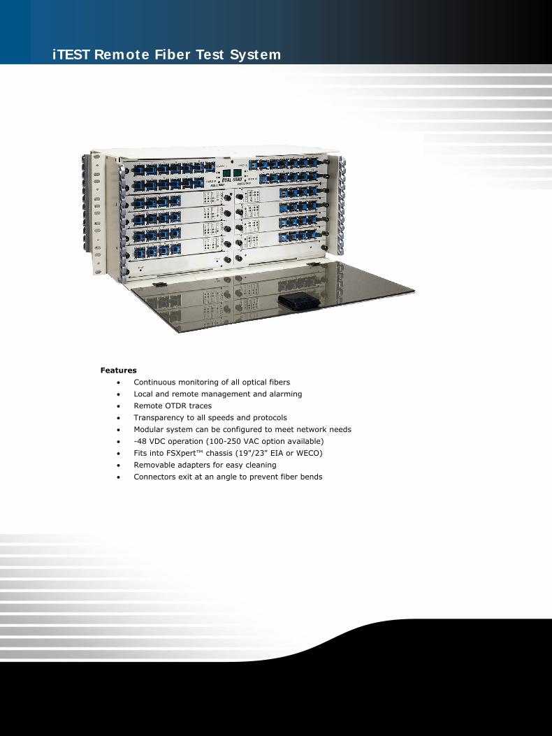
iTEST Remote Fiber Test System
Features
• Continuous monitoring of all optical fibers
• Local and remote management and alarming
• Remote OTDR traces
• Transparency to all speeds and protocols
• Modular system can be configured to meet network needs
• -48 VDC operation (100-250 VAC option available)
• Fits into FSXpert™ chassis (19"/23" EIA or WECO)
• Removable adapters for easy cleaning
• Connectors exit at an angle to prevent fiber bends

2w w w . a l c o n - t e c h . c o m • + 1 - 9 5 2 - 4 4 5 - 4 0 7 2
The Problem
As fiber optic networks evolve, installation and maintenance personnel need a flexible and efficient way to test during installation, maintenance, and repair procedures. Each fiber needs to be tested and characterized during installation to assure that the link meets all optical requirements and to establish an optical test reference. In order to maintain a high level of network performance after turn-up, preventive maintenance must be performed on a regular basis to monitor the fibers for degradation and other performance changes. Finally, in the event of a fiber cut, network degradation, or other physical layer network problems, quick and efficient troubleshooting must take place. Unfortunately, traditional fiber test equipment is either labor intensive manual gear requiring operator dispatches with the associated high costs, or automated Remote Fiber Test System (RFTS) equipment that is cost prohibitive for many carriers.
The Solution
Alcon Technologies solves the problems associated with fiber network testing with the iTEST Remote Fiber Test System. iTEST is a cost effective system that reduces the time and labor costs associated with installation, maintenance, and
fault location testing. iTEST provides installation and maintenance personnel the ability to single handedly access and test fibers from any location. This can reduce dispatches by over 75% and reduces the personnel and travel costs required to maintain and repair fiber networks. The iTEST System is non-intrusive, and can be used on dark and live traffic-carrying fibers.
iTEST Remote Fiber Test System
6/
06
•
81
90
00
5
iT
EST
RFT
S
3w w w . a l c o n - t e c h . c o m • + 1 - 9 5 2 - 4 4 5 - 4 0 7 2
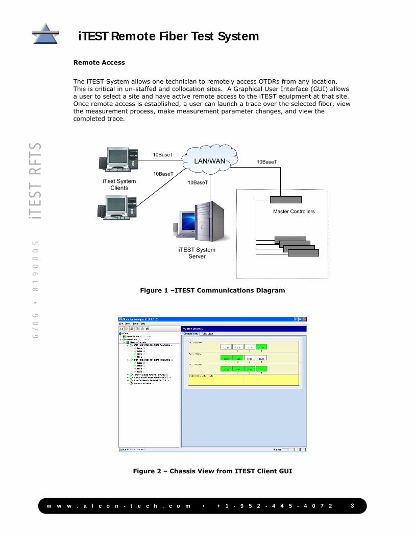
Remote Access
The iTEST System allows one technician to remotely access OTDRs from any location. This is critical in un-staffed and collocation sites. A Graphical User Interface (GUI) allows a user to select a site and have active remote access to the iTEST equipment at that site. Once remote access is established, a user can launch a trace over the selected fiber, view the measurement process, make measurement parameter changes, and view the completed trace.
Figure 1 –ITEST Communications Diagram
Figure 2 – Chassis View from ITEST Client GUI
Master Controllers
LAN/WAN 10BaseT
10BaseT
10BaseT
iTEST System Server
iTest System Clients
10BaseT
iTEST Remote Fiber Test System
6/
06
•
81
90
00
5
iT
EST
RFT
S
4w w w . a l c o n - t e c h . c o m • + 1 - 9 5 2 - 4 4 5 - 4 0 7 2
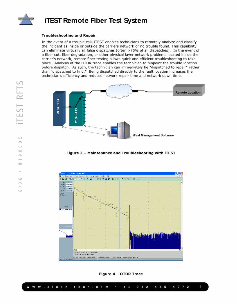
Troubleshooting and Repair
In the event of a trouble call, iTEST enables technicians to remotely analyze and classify the incident as inside or outside the carriers network or no trouble found. This capability can eliminate virtually all false dispatches (often >75% of all dispatches). In the event of a fiber cut, fiber degradation, or other physical layer network problems located inside the carrier’s network, remote fiber testing allows quick and efficient troubleshooting to take place. Analysis of the OTDR trace enables the technician to pinpoint the trouble location before dispatch. As such, the technician can immediately be “dispatched to repair” rather than “dispatched to find.” Being dispatched directly to the fault location increases the technician’s efficiency and reduces network repair time and network down time.
Figure 3 – Maintenance and Troubleshooting with iTEST
Figure 4 – OTDR Trace
O T D R
Remote Location
O T A U
iTest Management Software
iTEST Remote Fiber Test System
6/
06
•
81
90
00
5
iT
EST
RFT
S
5w w w . a l c o n - t e c h . c o m • + 1 - 9 5 2 - 4 4 5 - 4 0 7 2
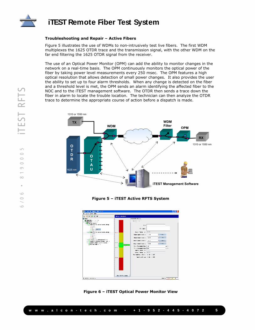
Troubleshooting and Repair – Active Fibers
Figure 5 illustrates the use of WDMs to non-intrusively test live fibers. The first WDM multiplexes the 1625 OTDR trace and the transmission signal, with the other WDM on the far end filtering the 1625 OTDR signal from the receiver. The use of an Optical Power Monitor (OPM) can add the ability to monitor changes in the network on a real-time basis. The OPM continuously monitors the optical power of the fiber by taking power level measurements every 250 msec. The OPM features a high optical resolution that allows detection of small power changes. It also provides the user the ability to set up to four alarm thresholds. When any change is detected on the fiber and a threshold level is met, the OPM sends an alarm identifying the affected fiber to the NOC and to the iTEST management software. The OTDR then sends a trace down the fiber in alarm to locate the trouble location. The technician can then analyze the OTDR trace to determine the appropriate course of action before a dispatch is made.
Figure 5 – iTEST Active RFTS System
Figure 6 – iTEST Optical Power Monitor View
O T D R
TX WDM
WDM Filter
RX
1625 nm
1310 or 1550 nm
O T A U
OPM
1310 or 1550 nm
iTEST Management Software
iTEST Remote Fiber Test System
6/
06
•
81
90
00
5
iT
EST
RFT
S
iTEST Remote Fiber Test System
6/
06
•
81
90
00
5
iT
EST
RFT
S
Alcon Technologies, Inc., 11201 Hampshire Ave S, Minneapolis, Minnesota USA 55438Specifications published here are current as of the date of publication of this document. Because we are continuously improving ourproducts, Alcon reserves the right to change specifications without prior notice. At any time, you may verify product specifications bycontacting us. Alcon Technologies, Inc. views its patent portfolio as an important corporate asset and vigorously enforces its patents.Products or features contained herein may be covered by one or more U.S. or foreign patents.
8190005 6/06 © 2006 Alcon Technologies, Inc. All Rights Reserved An Equal Opportunity Employer
Web Site: www.alcon-tech.com Customer Service: +1-952-445-4072 Fax: +1-952-445-4082 Email: [email protected]
System Components
Optical Power Monitor (OPM) The optical power monitors can play a critical role in the RFTS system. This device continuously monitors the fiber, taking power level measurements every 250 msec. The optical power monitor is a dedicated device, assuring there is no delay in detecting network problems. Its low 0.02 dB resolution allows detection of minor changes of power in the fiber. Optical Time Domain Reflectometer (OTDR) The OTDR pinpoints the trouble location in the fiber optic network. It uses 1330, 1550 nm, or 1625 nm wavelength to allow uninterrupted traffic while testing the network. Optical Test Access Unit (OTAU) The OTAU is a 1xN optical switch that enables use of the OTDR among multiple fibers in the network. This switch is available with 2 to 130 optical ports. Wave Division Multiplexer (WDM) and WDM Filter The WDM multiplexes the out-of-band OTDR trace at 1625 nm with the network traffic at 1310 or 1550 nm. A WDM filter is used to allow uninterrupted transmission during the testing process. Chassis and Controller The Chassis and Controller provide power and communication to all modules. The chassis mounts in a 19” or 23” rack, and uses redundant -48 VDC power input. The controller has an Ethernet and a serial interface for external communications. Different chassis types are available including 3RU and 5RU high (5. 25 and 8.75 inches).