low noise frequency stable fiber lasers for optical remote
TRANSCRIPT

Crystal Fibre • aeroLASE • Koheras • SuperK
Low Noise Frequency Stable Fiber Lasers for Optical Remote Sensing Applications
Jens Engholm Pedersen
Oct 22, 2012
NKT Photonics A/S Denmark

Crystal Fibre • aeroLASE • Koheras • SuperK
NKT Photonics
Crystal Fibre aeroGAIN SuperK Koheras
Argos
High Peak Power Pulsed Lasers • Material Processing • Military & Defense
• High-end research & development • Gyroscope
Replacement of conv. multiple lasers • Imaging (bio.)
• Inspection (semicon.) • High-end R&D
Advanced sensing • Wind LIDAR
• Seismic • Security
• SHM
Spectroscopy
• Military & Defense • High-end research &
development

Crystal Fibre • aeroLASE • Koheras • SuperK
1. Laser source requirements for remote sensing 2. What’s on the market? 3. Fiber DFB laser:
a) general operational principles b) noise c) new class of frequency stabilized fiber lasers
4. Applications 5. Summary
Fiber lasers for remote sensing:

Crystal Fibre • aeroLASE • Koheras • SuperK
Security Seismic Structural Health Monitoring
Vibrometry Wind LIDAR / Ranging
PDV
Pipes Fences Data
Oil &Gas exploitation Navy
Water pipes Oil and gas pipes Other
Laser Doppler vibrometry
Wind turbines Wind assessment Airports Atmospheric sensing Aircraft monitoring
Shock wave analysis @ km/sec velocities
fiber interferometry
Laser based remote sensing

Crystal Fibre • aeroLASE • Koheras • SuperK
Laser source requirements for remote sensing applications
Example: Wind LIDAR • back scatter coefficient from atmospheric aerosols <10-14
(depending on aerosol concentration (clean air is a problem!)) • => good signal-to-noise ratio requires high power + low noise
• Fiber optic sensing: low levels of change in phase, frequency or intensity ⇒
• low noise laser source – low phase & amplitude noise • compact • fiber coupled • maintenance free • frequency tuneability for some applications

Crystal Fibre • aeroLASE • Koheras • SuperK
Compact low noise laser sources NPRO laser has set the standard for compact low noise lasers for years. Last 10 years: new class of laser products for fiber optic and remote sensing.
SCL: RIO (talk later this session), Teraxion
Fiber lasers: Orbits Lightwave, NP Photonics, NKT Photonics
• greater wavelength selection • compact (similar foot print) • fiber coupled • maintenance free • single frequency • narrow linewidth • low phase noise – some
comparable to NPRO

Crystal Fibre • aeroLASE • Koheras • SuperK
Focus: Distributed Feed-Back Fiber Laser – UV processing
photo-sensitive & rare earth doped fiber
Pump light δlgap = λB/4 Stimulated laser emission at a wavelength λB
Typical length:
2 - 10 cm
passive fiber
passive fiber
Laser wavelength: λB = ΛB ∙ n(λB,ε,T)

Crystal Fibre • aeroLASE • Koheras • SuperK
Distributed Feed-back fiber laser - packaging
Fiber laser grating mounted under tension on substrate. λB = ΛB(ε,T) ∙ n(λB,ε,T) Fiber laser wavelength determined by grating pitch, tension, temperature
pump laser
Isolator
WDM coupler
10 – 50 mW

Crystal Fibre • aeroLASE • Koheras • SuperK
Single mode operation
Phase shifted FBG of DFB fiber laser:
• strong grating with narrow spectral width (< 100 pm)
• DFB cavity: FSR > grating bandwidth => robust single mode operation
• single mode operation un-changed during frequency tuning
• Polarization modes - degeneracy lifted through: − residual fiber birefringence − UV-induced birefringence
• Laser polarization modes discriminated through differential Q-values

Crystal Fibre • aeroLASE • Koheras • SuperK
Wavelength ranges
DFB fiber lasers
RE dopant Wavelength range
Yb 980-1200 nm
Er 1500-1620 nm
Tm 1730-2100 nm
Er3+:silica
Yb3+:silica Tm3+:silica
Crystal Fibre • aeroLASE • Koheras • SuperK
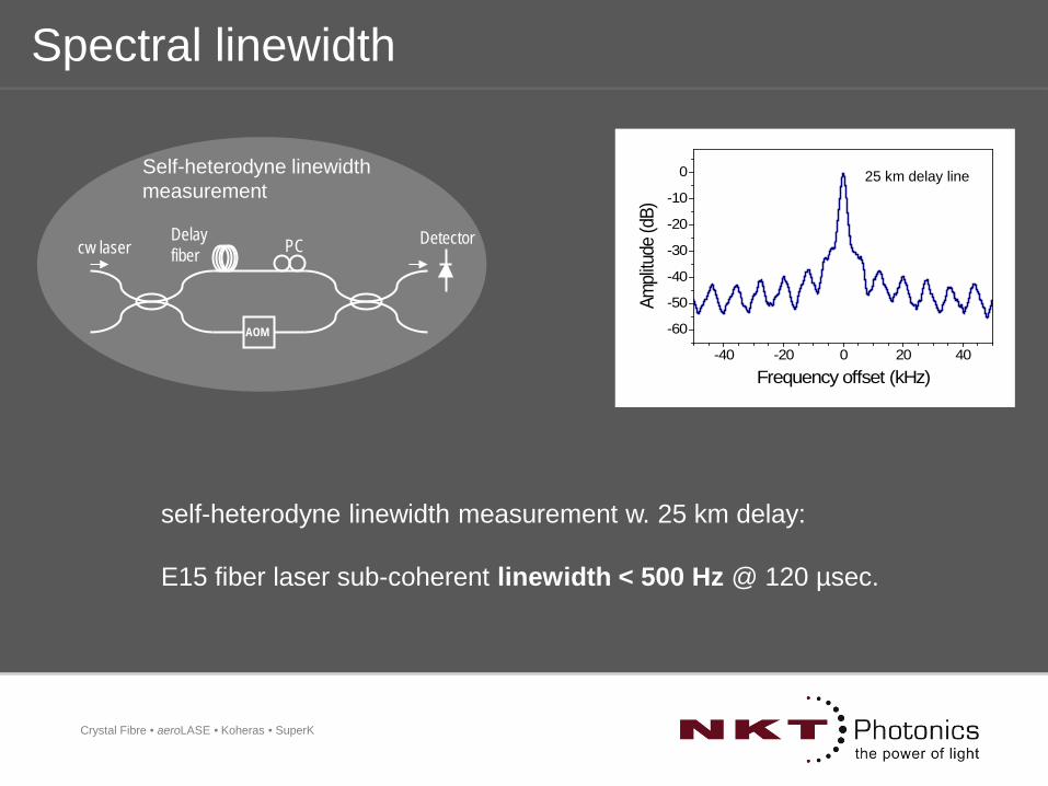
Spectral linewidth
self-heterodyne linewidth measurement w. 25 km delay: E15 fiber laser sub-coherent linewidth < 500 Hz @ 120 µsec.
-40 -20 0 20 40
-60
-50
-40
-30
-20
-10
0
Ampli
tude
(dB)
Frequency offset (kHz)
25 km delay line Self-heterodyne linewidth measurement
AOM
Detector Delay fiber PC cw laser

Crystal Fibre • aeroLASE • Koheras • SuperK
Coherence length
E15 fiber laser (free running) ~ 56 km
E15 fiber laser (locked) ~ 8000 km

Crystal Fibre • aeroLASE • Koheras • SuperK
Phase noise
Combination of fiber waveguide properties, FBG cavity and long rare earth lifetimes account for a very low level of phase noise
Key to optical remote sensing (Fiber Optic interferometric sensing)
E15 phase noise spec
Slavik et al, Southampton, OFS 2011
2
Geoseismic sensing limit

Crystal Fibre • aeroLASE • Koheras • SuperK
Frequency-lock fiber laser to compact & stable frequency reference:
Lower phase noise – higher frequency stability: A new class of frequency stabilized fiber lasers
compact & stable frequency
discriminator
laser
frequency stabilized laser output
laser frequency control (piezo tuning)
frequency stabilized fiber DFB laser module (X15)

Crystal Fibre • aeroLASE • Koheras • SuperK
Frequency-locking fiber laser on stablized frequency locker (stable interferometer)
• reduce phase noise by approx 20 dB
• Meet requirements for Geo-seismic fiber optic sensing: low phase noise @ low frequencies
Frequency noise reduction
-170
-150
-130
-110
-90
-70
0.1
1
10
100
1000
10000
1 10 100 1000
Phas
e N
oise
[dB(
rad R
MS)/
rt-H
z]
Freq
uenc
y Noi
se [H
z/rt
-Hz]
Frequency [Hz]
freq. stabilized laser
non-stabilized laser
Geoseismic limit

Crystal Fibre • aeroLASE • Koheras • SuperK
Frequency stability over time
• Locked laser shows clear improvement in frequency stability over time
• Frequency drift < 1 MHz/10 hours
-6
-4
-2
0
2
4
6
8
10
0 2 4 6 8 10 12 14 16
Beat
freq
uenc
y (M
Hz)
Time (h)
un-lockedlocked
frequency stability - free running vs. freq. stabilized

Crystal Fibre • aeroLASE • Koheras • SuperK
Frequency stability – Allan Variance analysis
1.E-13
1.E-12
1.E-11
1.E-10
1.E-09
1.E-08
1.E-07
1.E-06 1.E-05 1.E-04 1.E-03 1.E-02 1.E-01 1.E+00 1.E+01 1.E+02 1.E+03 1.E+04 1.E+05
Alla
n de
viat
ionσ
y(t)
σy2 (
t) =
½<(
y n+1
-yn)
2 >, y
n=
<dν/ν>
n
Sample period (s)
Allan variance: E15PM BasiK and X15PM
E15 S/N 09220147 & 09220149X15 S/N 12110179 & 12110180X15 S/N 12110179 & 12110181X15 S/N 12110179 & 12110182X15 S/N 12110179 & 12110182 unlocked

Crystal Fibre • aeroLASE • Koheras • SuperK
Fiber DFB laser frequency tuning
λB = ΛB(ε,T) ∙ n(λB,ε,T) Laser grating bonded to susbtrate => change wavelength by changing substrate length
Slow tuning - thermal tuning – mount fiber laser grating on e.g. aluminum substrate:
1. Fiber laser wavelength tunes as:
2. Tuning range approx. 1 nm or 125 GHz
@ 1550nm
3. Slow tuning: approx. 1 GHz/sec
4. Single mode operation maintained during tuning
fibersubstraten
nTn
ndTd α
εαλ
λ•
∂∂
•+∂∂
•+=•111

Crystal Fibre • aeroLASE • Koheras • SuperK
Fast tuning - piezo frequency tuning
1
10
100
1000
0.1 1 10 100 1000 10000 100000
Wav
elen
gth
tuni
ng (M
Hz/
V)
Modulation frequency (Hz)
1.Piezo electric transducer built into substrate
2.Fiber laser wavelength tunes with ΛB (Upiezo)
2.Tuning range. 25 - 500 pm or 3- 62 GHz @ 1550nm depending on piezo type
3.Tuning speed
4.Single mode operation maintained during tuning
Piezo: 10 GHz @ 200 V

Crystal Fibre • aeroLASE • Koheras • SuperK
Frequency tuneable FL: application in Frequency-conversion PDV
“Limiting performance can be achieved at any (measurable) velocity!” ref.: D.H.Dolan, PDV Workshop, Sept. 2010
master laser
slave laser
PD mixer
RF generator
Fast laser frequency control
phase meter
Lock reference laser (laser 2) to pre-set frequency offset from target laser (laser 1) using PZT frequency tuning:
Frequency-conversion PDV:

Crystal Fibre • aeroLASE • Koheras • SuperK
Koheras Laser Solutions
BasiK Module
AdjustiK System
AcoustiK System
BoostiK Module
BoostiK System
• Low to high power • Single to multi wavelengths • Laser properties are the same
10 W @ 1550
1 W @ 1550
10 – 50 mW @ 1550

Crystal Fibre • aeroLASE • Koheras • SuperK
Multi-channel source
AcoustiK System
up to 32 channels multiplexed in a single PM fiber

Crystal Fibre • aeroLASE • Koheras • SuperK
Security Seismic Structural Health Monitoring
Vibrometry Wind LIDAR / Ranging
Injection seeding
Scientific Instrumentation
Space Fusion
Pipes Fences Data
Oil &Gas exploitation Navy
Water pipes Oil and gas pipes Other
Laser Doppler vibrometry
Wind turbines Wind assessment Airports Atmospheric sensing Aircraft monitoring
High power YAG lasers
Spectroscopy Atomic physics
Magnetic field surveys Gravitational wave detection Telescope radio antennas
Fusion energy
Sensor interferometry Instrumentation & Science LIDAR
Koheras Laser Key Applications

Crystal Fibre • aeroLASE • Koheras • SuperK
Summary
The DFB Fiber Laser is a perfect match for fiber optic sensing applications:
compact, fiber coupled laser source single mode – also under frequency tuning low phase noise & narrow linewidth ~ long coherence length fast & wide range frequency tuning - 10’s of GHz tuning @ kHz speed high power (up to 10 W @ 1550nm) multi-wavelength systems remote digital control

Crystal Fibre • aeroLASE • Koheras • SuperK
Questions?

Crystal Fibre • aeroLASE • Koheras • SuperK
Application slides .......

Crystal Fibre • aeroLASE • Koheras • SuperK
27
• Laser radiation scatters from atmospheric aerosols • Aerosol movement follows the wind • Scattered radiation is ‘Doppler’ shifted by the wind speed • Measure ‘in-line’ component of wind speed
LASER
DETECTOR TARGET
transmitted light
Doppler shift
local oscillator
CW LIDAR: Wind speed measurement
Courtesy of:
coherent detection

Crystal Fibre • aeroLASE • Koheras • SuperK
CW LIDAR: ranging
CW LIDAR range information:
dominant contribution to scattering comes from focus region (within Rayleigh length)
A CW LIDAR lacks the ranging that is inherent to a pulsed system
⇒range resolution depends on distance.
⇒Max range limited to a few x 100 m

Crystal Fibre • aeroLASE • Koheras • SuperK
LIDAR & laser noise
shot noise & coherent noise
-165
-160
-155
-150
-145
-140
-10 -8 -6 -4 -2 0 2 4 6 8 10frequency [MHz]
Noi
se s
pect
ral d
ensi
ty [d
Bm
/Hz]
Shot noise
Coherent noise @ LW
Coherent noise @ linewidth 10 x LW
Coherent noise @ linewidth 100 x LW
LASER
DETECTOR
transmitted light
Doppler shifted back-
scattered light
local oscillator (reference beam)
spurious reflections in LIDAR optics ⇒ • coherent white noise floor • magnitude depends on
spectral linewidth of LIDAR laser
• level may increase beyond shot noise
⇒ sensitivity of CW LIDAR system depends on laser linewidth

Crystal Fibre • aeroLASE • Koheras • SuperK
CW Wind LIDAR: Natural Power ZephIR
Courtesy of Natural Power

Crystal Fibre • aeroLASE • Koheras • SuperK
PDV vs wind LIDAR – laser noise requirements
PDV: probe return 10-4
Wind LIDAR: return 10-14
=> noise impact: Wind LIDAR requires shot noise limited detection (RIN shot noise limited, narrow linewidth to reduce coherent noise from residual reflections and non-perfect isolation in system)

Crystal Fibre • aeroLASE • Koheras • SuperK
PDV vs wind LIDAR
Crystal Fibre • aeroLASE • Koheras • SuperK
PDV & laser requirements
The main disadvantage of the heterodyne system compared to the Fabry-Perot or VISAR techniques is the limited maximum velocity of the heterodyne method. The velocity range of the Fabry-Perot or VISAR may be adjusted to arbitrarily high velocity by the choice of etalons. The heterodyne system described here is limited by the bandwidth of the high-sample-rate digitizer. “A Novel System for High- Speed Velocimetry Using Heterodyne Techniques” O. T. Strand, D. R. Goosman, C. Martinez, T. L. Whitworth, W. W. Kuhlow Review of Scientific Instruments 2005
The phenomenon of shock waves reaching the measurement surface is known as shock breakout. The time from detonation to shock breakout is about 1 to 2 μsec. The primary goal of velocimetry is to capture the initial details of the shock breakout. Unfortunately, these measurements are the most difficult to achieve. A secondary goal is to capture the evolution of surface velocities in the first 15 mm of travel, as the target begins to spall. “Design, construction, alignment, and calibration of a compact velocimetry experiment” Morris I. Kaufman*a, Robert M. Malonea, Brent C. Froggeta, David L. Esquibela, Vincent T. Romeroa, Gregory A. Larea, Bart Briggsa, Adam J. Iversona, Daniel K. Frayera, Douglas DeVorea, Brian Cataa, David B. Holtkampb, Mark D. Wilkeb, Nick S. P. Kingb, Michael R. Furlanettob, Matthew E. Briggsb, Michael D. Furnishc DOE/NV/25946--250

Crystal Fibre • aeroLASE • Koheras • SuperK
Acoustic sensing: Geo-seismic sensing for Oil & Gas
page 34
Geoseismic sensing: airgun + hydrophone array.
•Systems traditionally based on electric transducers (e.g. piezo electric hydrophones)
•systems based on fibre optical sensors now available
Search for new oilfields (streamers)
Permanent reservoir monitoring (e.g. this conference presentation SWA1)

Crystal Fibre • aeroLASE • Koheras • SuperK
Fiber optical hydrophones
page 35
• Laser used as interrogator for phase changes in fiber optical interferometer • Key laser parameter: LOW PHASE NOISE • Fiber Lasers ideal candidates for fiber optic geoseismic sensor systems
FBG FBG
Grating based interferometry (Optoplan / this conf.: SWA1)
Fiber optic un-balanced Mach-Zender interferometer
Delay fiber

Crystal Fibre • aeroLASE • Koheras • SuperK
Acoustic sensing: Fiber laser direct hydrophone element
Courtesy of:

Crystal Fibre • aeroLASE • Koheras • SuperK
Fiber laser hydrophone – basic configuration
Courtesy of:

Crystal Fibre • aeroLASE • Koheras • SuperK
Fence/ Borders
Perimeter/ tunnels Oil or Gas Pipe
Acoustic sensing: Pipeline Monitoring / perimeter security
• Distributed fiber sensor, ~ 100 km
• long base-line interferometers
• DFB fiber laser: long coherence length
• Observing phase-shift of signal
• Acoustic ”Finger print” of intruder
Reference: Future Fibre Technologies, Australia

Crystal Fibre • aeroLASE • Koheras • SuperK
FFT Microstrain Locator Technology Bidirectional fibre optic Mach Zehnder interferometer with counter-propagating signals.
Event location resolved by measuring time difference between counter propagating signals.
Requires highly coherent laser (low phase noise)