introduction to synchronous...
TRANSCRIPT
1
Introduction to Synchronous Machines
Definition:
A synchronous machine is an ac rotating machine whose speed under
steady state condition is proportional to the frequency of the current in its
armature. The magnetic field created by the stator currents rotates at the
synchronous speed ,and that created by the field current on the rotor is
rotating at the synchronous speed also, and a steady torque results. So,
these machines are called synchronous machines because they
operate at constant speeds and constant frequencies under steady-
state conditions. Synchronous machines are commonly used as
generators especially for large power systems, such as turbine generators
and hydroelectric generators in the grid power supply. Because the rotor
speed is equal to the synchronous speed of stator magnetic field,
synchronous motors can be used in situations where constant speed drive is
required. Since the reactive power generated by a synchronous machine can
be adjusted by controlling the magnitude of the rotor field current,
unloaded synchronous machines are also often installed in power systems
for power factor correction or for control of reactive kVA flow. Such
machines, known as synchronous condensers, and may be more
economical in the large sizes than static capacitors.
The bulk of electric power for everyday use is produced by polyphase
synchronous generators( alternators), which are the largest single-unit
electric machines in production. For instance, synchronous generators
with power ratings of several hundred megavolt-amperes (MVA) are
fairly common, and it is expected that machines of several thousand
megavolt- amperes will be in use in the near future. Like most rotating
machines, synchronous machines are capable of operating both as a
motor and as a generator. They are used as motors in constant-speed
drives, and where a variable-speed drive is required ,a synchronous
motor is used with an appropriate frequency changer such as an
inverter. As generators, several synchronous machines often operate
in parallel, as in a power station. While operating in parallel, the
generators share the load with each other; at a given time one of the
generators may not carry any load. In such a case, instead of shutting
down the generator, it is allowed to "float" on the line as a
synchronous motor on no-load.
2
Construction of synchronous machines : The synchronous machine has 3 phase winding on the stator and a d.c. field winding
on the rotor.
1. Stator : It is the stationary part of the machine and is built up of sheet-steel laminations
having slots on its inner periphery. A 3-phase winding is placed in these slots. The
armature winding is always connected in star and the neutral is connected to ground.
2. Rotor : The rotor carries a field winding which is supplied with direct current through two slip
rings by a separate d.c. source. Rotor construction is of two types, namely;
(i) Salient (or projecting) pole type .
(ii) Non-salient (or cylindrical) pole type .
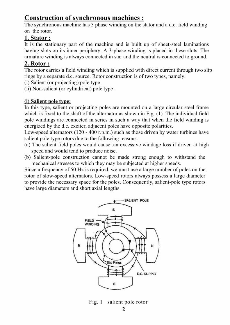
(i) Salient pole type:
In this type, salient or projecting poles are mounted on a large circular steel frame
which is fixed to the shaft of the alternator as shown in Fig. (1). The individual field
pole windings are connected in series in such a way that when the field winding is
energized by the d.c. exciter, adjacent poles have opposite polarities.
Low-speed alternators (120 - 400 r.p.m.) such as those driven by water turbines have
salient pole type rotors due to the following reasons:
(a) The salient field poles would cause .an excessive windage loss if driven at high
speed and would tend to produce noise.
(b) Salient-pole construction cannot be made strong enough to withstand the
mechanical stresses to which they may be subjected at higher speeds.
Since a frequency of 50 Hz is required, we must use a large number of poles on the
rotor of slow-speed alternators. Low-speed rotors always possess a large diameter
to provide the necessary space for the poles. Consequently, salient-pole type rotors
have large diameters and short axial lengths.
Fig. 1 salient pole rotor

3
(ii) Non-salient pole(cylindrical) type :
In this type, the rotor is made of smooth solid forged-steel radial cylinder having a
number of slots along the outer periphery. The field windings are embedded in
these slots and are connected in series to the slip rings through which they are
energized by the d.c. exciter. The regions forming the poles are usually left
unslotted as shown in Fig. (2). It is clear that the poles formed are non-salient i.e.,
they do not project out from the rotor surface.
Fig. 2 cylindrical rotor
High-speed alternators (1500 or 3000 r.p.m.) are driven by steam turbines and
use non-salient type rotors due to the following reasons:
(a) This type of construction has mechanical robustness and gives noiseless
operation at high speeds.
(b) The flux distribution around the periphery is nearly a sine wave and hence
a better e.m.f. waveform is obtained than in the case of salient-pole type.
Since steam turbines run at high speed and a frequency of 50 Hz is required, we
need a small number of poles on the rotor of high-speed alternators (also called
turboalternators). We can use not less than 2 poles and this fixes the highest
possible speed. For a frequency of 50 Hz, it is 3000 r.p.m. The next lower speed is
1500 r.p.m. for a 4-pole machine. Consequently, turboalternators possess 2 or 4
poles and have small diameters and very long axial lengths.
4
Classification of synchronous machines according to the form of excitation:
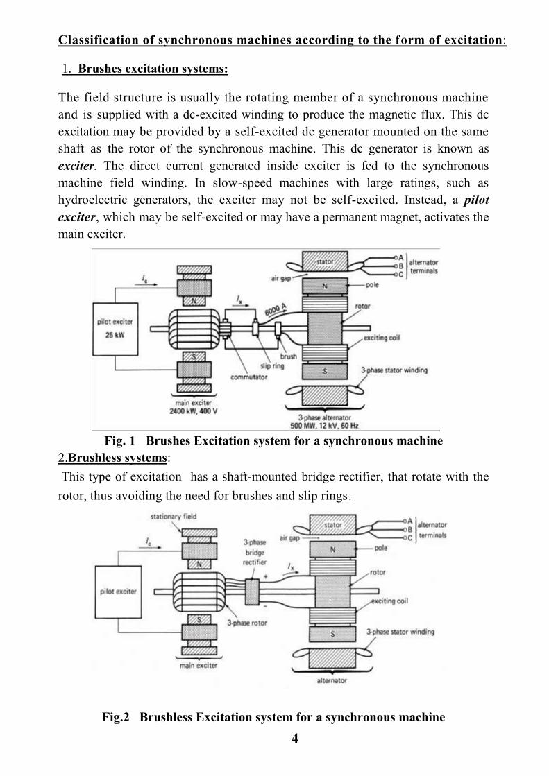
1. Brushes excitation systems:
The field structure is usually the rotating member of a synchronous machine
and is supplied with a dc-excited winding to produce the magnetic flux. This dc
excitation may be provided by a self-excited dc generator mounted on the same
shaft as the rotor of the synchronous machine. This dc generator is known as
exciter. The direct current generated inside exciter is fed to the synchronous
machine field winding. In slow-speed machines with large ratings, such as
hydroelectric generators, the exciter may not be self-excited. Instead, a pilot
exciter, which may be self-excited or may have a permanent magnet, activates the
main exciter.
Fig 1 Block Diagram of Excitation system by pilot &main
Fig. 1 Brushes Excitation system for a synchronous machine
2.Brushless systems:
This type of excitation has a shaft-mounted bridge rectifier, that rotate with the
rotor, thus avoiding the need for brushes and slip rings.
Fig.2 Brushless Excitation system for a synchronous machine

5
3.static systems:
This type of exctation is widely used in small size alternators, in which portion of
the AC from each phase of synchronous generator is fed back to the field winding
as a DC excitation through a system of transformer ,rectifiers and reactors.
External source of a DC is necessary for initial excitation of the field windings.
Advantages of stationary armature ;
The field winding of an alternator is placed on the rotor and is connected to d.c.
supply through two slip rings. The 3-phase armature winding is placed on the stator.
This arrangement has the following advantages:
(i) It is easier to insulate stationary winding for high voltages , because they are not
subjected to centrifugal forces .
(ii) The stationary 3-phase armature can be directly connected to load without going
through large, unreliable slip rings and brushes.
(iii) Only two slip rings are required for d.c. supply to the field winding on the rotor.
Since the exciting current is small, the slip rings and brush gear required are of light
construction.
(iv) Due to simple and robust construction of the rotor, higher speed of rotating d.c.
field is possible. This increases the output obtainable from a machine of given
dimensions.
Cooling :
Because synchronous machines are often built in extremely large sizes, they
are designed to carry very large currents. A typical armature current density
may be of the order of 10 A/mm2 in a well-designed machine. Also, the
magnetic loading of the core is such that it reaches saturation in many regions.
The severe electric and magnetic loadings in a synchronous machine produce
heat that must be appropriately dissipated. Thus the manner in which the
active parts of a machine are cooled determines its overall physical structures.
In addition to air, some of the coolants used in synchronous machines include
water, hydrogen, and helium.

6
Damper Bars :
So far we have mentioned only two electrical windings of a synchronous machine:
the three-phase armature winding and the field winding. We also pointed out that,
under steady state, the machine runs at a constant speed, that is, at synchronous
speed. However, like other electric machines, a synchronous machine undergoes
transients during starting and abnormal conditions. During transients, the rotor may
undergo mechanical oscillations and its speed deviates from the synchronous speed,
which is an undesirable phenomenon. To overcome this, an additional set of
windings, resembling the cage of an induction motor, is mounted on the rotor. When
the rotor speed is different from the synchronous speed, currents are induced in
the damper windings .the damper winding acts like the cage rotor of an induction
motor, producing a torque to restore the synchronous speed. Also, the damper bars
provide a means of starting to the synchronous motors, which is otherwise not self-
starting. Fig6 shows the damper bars on a salient rotors
Fig .6 salient pole rotor showing the field winding and damper bars

7
Differences between three phase induction machine and synchronous machine
Synchronous machine Three phase induction machine
Stator phase are star connected only
connected Stator phases either star or delta
Rotor windings are fed by dc source.
Rotor windings are not fed by electricity,
currents flow through rotor due to induction
process.
Run at synchronous speed for both motor and
generator
Run below synchronous speed, as a motor
Run above synchronous speed, as a generator
Need damper bars to start , as a motor
Self starting , as a motor
Operate with lagging, leading, and unity power
factor
Operate with lagging power factor only
Complex in construction , expensive.
Simple in construction , rugged, low
maintenance, cheap , especially in squirrel cage
type.
Active in both low and high speed operation
, as a motor
Not active in low speed operation, as a motor
Used widely in generation of electricity
Not active in generating mode
Precise speed regulation, as a motor
Difficult in speed regulation, as a motor

8
THREE PHASE STATOR WINDINGS
The stator windings for alternating-current motors and generators are alike. It should be
noted that direct-current and alternating-current windings differ essentially by the former
being of the closed-circuit type (through commutator) ,while alternating-current windings
are of the open-circuit type.
Types of A-C Windings: With reference to the arrangements of coils used in three phase stator, windings may be
divided into two general classes as follows:
I. Distributed Windings:
1. Spiral or chain.
2. Lap.
3. Wave.
II. Concentrated Windings:
1. Lap.
2. Wave.
Distributed Windings: An armature winding which has its conductors of any one phase under a single pole placed
in several slots, is said to be distributed. When these conductors are bunched together in
one slot per pole per phase, the winding is called concentrated. It is usual in a distributed
winding to distribute the series conductors in any phase of the winding among two or more
slots under each pole. A distributed winding has two principal advantages, first, a distributed
winding generates a voltage wave that is nearly a sine curve, secondly, copper is evenly
distributed on the armature surface, therefore, heating is more uniform and this type of
winding is more easily cooled.
Concentrated Windings: The concentrated winding gives the largest possible emf from a given number of conductors
in the winding. That is for a definite fixed speed and field strength in an alternator, the
concentrated winding requires a less number of conductors than a distributed winding, but
increases the number of turns per coil.
Lap and Wave Windings:
Both distributed and concentrated windings make use of lap and wave connections. These
arrangements are in principle the same as used in direct-current windings. The diagrams of
Figs. 1 and 2 show distributed lap and wave windings .

9
Fig. 1 Single-phase lap winding
Fig 2. Three-phase wave winding , using one slot per pole per phase, star-connected.
Chain Winding : In this winding as shown in Fig. 3 there is only one coil side in a slot. An odd or even
number of conductors per slot may be used but several shapes of coils are required since the
coils enclose each other. The number of coils required in this winding is also small
compared with other windings. This type of winding is mainly used in alternating current
generators.
Fig. 3 Three-phase chain winding

10
Single layer and double layer winding :
In double layer winding two coil sides are located in each armature slot [Fig. 4 ].
If there is only one coil side located in each armature slot, the winding is called
single layer.
Fig. 4 A double layer winding. One side of the coil lies in the top of the slot and the other side in the
bottom of the of the slot.
Full pitch and fractional pitch windings:
For a three-phase winding the total number of coil sides or the total number of slots should
be just divisible by three (the number of phases) and sometimes by the number of poles.
This will result in a full pitch winding, that is, a winding in which a coil spans exactly the
distance between the centers of adjacent poles. If the coil spans less than this distance, so
that its two sides are not exactly under the centers of adjacent poles at the same time, it is
said to have a fractional-pitch. When a fractional pitch is used, the total number of slots
per phase must be a whole number. The fractional-pitch coils are frequently used in a.c.
machines for two main reasons. First, less copper is required per coil and secondly the
waveform of the generated voltage is improved .The number of stator slots, divided by the
number of poles gives a value of the pole pitch expressed in terms of the slots. Coil pitch
is expressed as a fraction of the pole pitch, in slots, or in electrical degrees. In the case of a
6 pole machine having 72 stator slots, and a double-layer winding, the pole pitch would be
12 slots(72 / 6). If the coil pitch were given as 2/3, this would be 120° ( 2/3 * 180°) or 8
slots (2/3 * 12). A full coil pitch for this winding would be 180 degrees, or 12 slots. A full
pitch winding is one in which the coil pitch is equal to the pole pitch, and a fractional pitch
winding is one in which the coil pitch is not equal to the pole pitch. For the coils used in
small machines round insulated wire is most employed. These coils are either wound in
the slots by hand or assembled by use of specially formed coils wound in forms and
insulated before being placed in the slots. Such formed coils are usually used except in
cases where the slots are closed or nearly closed. For large machines where the amperes to
be carried in each armature circuit is a large value, copper straps are frequently employed
for making up the armature coils. In very large machines a copper bar is used instead of
the copper straps. In such a case one bar serves as a conductor of a coil having one turn per
slot. The copper bars are connected to the end connections of the coils by brazing, welding
or bolting. In all cases, whatever the construction of the coil used, the slots must be
properly insulated with mica, polyester film or other suitable insulating material according

11
to the adequate class of insulation. The coil throw refers to the start of coil from one stator
slot to the finish of this coil at another stator slot . Figures 5 (a) , (b) , (c), and (d) show
four different coils, in each of them the pole pitch is of 12 slots while the coil pitch in (a) is
11 slots , in (b) is 13 slots, in (c) is 9 slots, and in (d) is 15 slots .
Fig. 5. Possible pitch for one coil per slot windings(pole pitch=24 slots/2poles=12) (a) coil throw 1 to 12,
coil pitch=12-1=11 (b) coil throw 1 to 14, coil pitch=14-1=13 (c) coil throw 1 to 10, coil pitch=10-1=9 ,
(d) coil throw 1 to 16, coil pitch=16-1=15 .
Phase belt and phase spread :
A group of adjacent slots belonging to one phase under one pole pair is known
as phase belt. The angle subtended by a phase belt is known as phase spread.
The 3-phase windings are always designed for 60° phase spread . Fig. (6)
shows a 2-pole, 3-phase double-layer, full pitch, distributed winding for the
stator of an alternator. There are 12 slots and each slot contains two coil sides.
The coil sides that are placed in adjacent slots belong to the same phase such
as( a1, a3 ) or (a2, a4 )constitute a phase belt. Since the winding has double-
layer arrangement, one side of a coil, such as (a1), is placed at the bottom of a
slot and the other side (- a1 ) is placed at the top of another slot spaced one pole
pitch apart. Note that each coil has a span of a full pole pitch or 180 electrical
degrees. Therefore. the winding is a full-pitch winding. Note that there are 12
total coils and each phase has four coils. The four coils in each phase are
connected in series so that their voltages aid. The three phases then may be
connected to form Y or -connection. Fig. (7) shows how the coils are

12
connected to form a Y-connection. Any star diagram can be readily changed
into a corresponding delta diagram by opening the star points and connecting
the inner end of phase A to the outer end of phase B, the inner end of phase B
to the outer end of phase C , and the inner end of phase C to the outer end of
phase A .
Fig. 6 Fig. 7
Simple rule for checking proper phase relationship in a three-phase winding:
A fundamental consideration when checking the instantaneous flow of current
in a three phase circuit, is to imagine that when the current flows in the same
direction in two legs of the circuit, it flows in the opposite direction in the third
leg. This principle can be applied to both motors and generators. In Figure 8, it
must be supposed that current flows in all three leads of the star connection
toward the point of the star connection. And that in the case of a delta
connection the current flows around the three sides of the delta in the same
direction. Then in either case for a three-phase winding, the polarity of each of
the pole-phase groups will alternate regularly around the winding and can be
indicated by arrows as in Fig. 8. By the use of this scheme there is no chance

13
for a reversal of a phase to be passed by not noticed when checking the
winding.
. Fig. 8 Simple scheme of alternately reversing arrows of pole-phase groups to check correct phase
polarity of a 3-phase winding. It is supposed in this case that current flows in the three leads
toward the star points of the winding which are indicated thus ( *) .
Why the alternators have their windings connected in star?
Because the star connection has the following advantages over delta connection:
(i) To obtain a desired voltage between outside terminals of a generator, the voltage built up in any one phase need be only 58 percent(1 / √3) of the terminal value. Hence only 58 percent of the turns required for a Δ-connected armature are necessary with a consequent lowering of insulation cost.
(ii) A star connected winding offers the advantage of a fourth or neutral lead making possible the advantages of a four -wire system, with or without grounded neutral.
(iii)The wave shape of a star-connected winding is improved, owing to the elimination of third harmonics and multiples of third harmonics from the terminal voltage. Fig.9 shows a star connected armature( stator), The terminal voltages E12, E23 and,E31 are 120 electrical degrees apart. In the third harmonics the e.m.f.'s of three phases (e01 ,e02 ,e03) are being in phase(3 X 120º = 360º= 0º ),to obtain terminal voltages, the resultant is zero. Hence no third harmonics appears between terminals.The circulating currents from the third harmonics cause unnecessary losses and dangerous heating in Δ-connected alternator, where it is not in the Y-connected alternator case. In addition the use of

14
a(5/6)th pitch winding in three-phase Y-connected generators reduces the fifth and seventh harmonics, if pesent, to almost nil, so the lowest harmonics that can be present is eleventh.
Fig. 9

15
Windings factors:
The stator winding of synchronous machine is distributed over the entire stator.
The distributed winding produces nearly a sine waveform and the heating is
more uniform. Likewise, the coils of armature winding are not full-pitched i.e.,
the two sides of a coil are not at corresponding points under adjacent poles. The
fractional pitched armature winding requires less copper per coil and at the
same time waveform of output voltage is improved. The distribution and
pitching of the coils affect the voltages induced in the coils. We shall discuss
two winding factors:
(i) Distribution factor (Kd).
(ii) Pitch factor (Kp).
(i) Distribution factor (Kd) :
A winding with only one slot per pole per phase is called a concentrated
winding. In this type of winding, the e.m.f. generated/phase is equal to the
arithmetic sum of the individual coil e.m.f.s in that phase. However, if the
coils/phase are distributed over several slots in space (distributed winding), the
e.m.f.s in the coils are not in phase (i.e., phase difference is not zero) but are
displaced from each by the slot angle (The angular displacement in electrical
agrees between the adjacent slots is called slot angle). The e.m.f./phase will be
the phasor sum of coil e.m.f.s. The distribution factor Kd is defined as:
The distribution factor can be determined by constructing a phasor diagram for
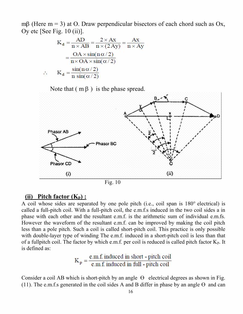
the coil e.m.f.s. Let m = 3. The three coil e.m.f.s are shown as phasors AB, BC
and CD [See Fig. 10 (i)] each of which is a chord of circle with centre at O and
subtends an angle at O. The phasor sum of the coil e.m.f.s subtends an angle
16
m(Here m = 3) at O. Draw perpendicular bisectors of each chord such as Ox,
Oy etc [See Fig. 10 (ii)].
Note that ( m is the phase spread.
Fig. 10
(ii) Pitch factor (Kp) : A coil whose sides are separated by one pole pitch (i.e., coil span is 180electrical) is
called a full-pitch coil. With a full-pitch coil, the e.m.f.s induced in the two coil sides a in
phase with each other and the resultant e.m.f. is the arithmetic sum of individual e.m.fs.
However the waveform of the resultant e.m.f. can be improved by making the coil pitch
less than a pole pitch. Such a coil is called short-pitch coil. This practice is only possible
with double-layer type of winding The e.m.f. induced in a short-pitch coil is less than that
of a fullpitch coil. The factor by which e.m.f. per coil is reduced is called pitch factor Kp. It
is defined as:
Consider a coil AB which is short-pitch by an angle Өelectrical degrees as shown in Fig.
(11). The e.m.f.s generated in the coil sides A and B differ in phase by an angle Өand can

17
be represented by phasors EA and EB respectively as shown in Fig. (12). The diagonal of the
parallelogram represents the resultant e.m.f. ER of the coil.
Fig. 11 Fig. 12
For a full-pitch winding, Kp = 1. However, for a short-pitch winding, Kp < 1.
Note that Өis always an integer multiple of the slot angle .

18
SYNCHRONOUS GENERATOR
The machine which produces 3-phase electrical power from mechanical power is called
an alternator or synchronous generator. Alternators are the primary source of all the
electrical energy we consume. These machines are the largest energy converters found
in the world.
Alternator Operation : Like the dc generator, a synchronous generator functions on the basis of Faraday's
law, which state if the flux linking the coil changes in time, a voltage is induced
in a coil. Stated in another form, a voltage is induced in a conductor if it cuts
magnetic flux lines. The rotor winding is energized from the d.c. exciter and alternate N
and S poles are developed on the rotor. When the rotor is rotated by a prime mover, the
stator or armature conductors are cut by the magnetic flux of rotor poles. Consequently,
e.m.f. is induced in the armature conductors due to electromagnetic induction. The
induced e.m.f. is alternating since N and S poles of rotor alternately pass the armature
conductors. The frequency of induced e.m.f. is given by;
Where N = speed of rotor in r.p.m. ,
P = number of rotor poles.
The magnitude of the voltage induced in each phase depends upon the rotor flux, the
number and position of the conductors in the phase and the speed of the rotor.
[Fig. 1 (i)] shows star-connected armature winding and d.c. field winding. When the rotor
is rotated, a 3-phase voltage is induced in the armature winding.. The magnitude of e.m.f.
in each phase of the armature winding is the same. However, they differ in phase by 120°
electrical as shown in the phasor diagram [ Fig. 1 (ii)].
Fig. 1

19
Considering the round rotor synchronous generator in Fig.2,which shows a simple
consentrated stator winding ( 1 slot / pole / phase).
Fig .2 (a) A round rotor synchronous generator
(b) Air gap flux density distribution produced by the rotor excitation
and assuming that the flux density in the air gap is uniform implies that sinu-
soidally varying voltages will be induced in the three coils aa' ,bb' and cc' if the rotor,
rotates at a synchronous speed, Ns. Also if Φр is the flux per pole, ω is the angular
frequency, and T is the number of turns in phase a (coil aa'), then the voltage
induced in phase a is given as:
ea = ω T Φр sin ωt
= Em sin ωt
Where Em = ω T Φр , and ω =2 π f .
Because phases b and c are displaced from phase a by +_ 120º , the corresponding
voltages may be written as
eb = Em sin (ωt – 120º)
ec = Em sin (ωt + 120º)
These voltages are sketched in Fig. 3 and correspond to the voltages from a three-
phase generator.

20
Fig. 3 A three-phase voltage produced by a three-phase synchronous generator
Generated E.M.F. Equations:
The magnetic flux cut by one armature conductor, when the rotor of an alternator is made to revolve through one revolution, is Φр * P, where Φр is the magnetic flux per pole and P is the number of poles. If N is the speed in revolution per minute, then the flux cut per second becomes
Φр * P *( N /60)
Since 1 volt is generated when 1 weber of flux is cut per second, the average voltage generated in this conductor becomes
Eav = Φр * P *( N /60) volts
If the total number of conductors on the armature is Z and they are connected into A parallel paths, the average voltage between terminals becomes Eav per conductor * ( Z / A )
In case of alternating current generators the e.m.f. depends not only upon the total flux cut per second but also upon the way in which the flux and the conductors are distributed. A change in distribution of flux changes the relative values of the maximum and effective (r.m.s.) e.m f.'s.
In addition, the e.m.f. built up in any one conductor, when considered vectorially, cannot always be added directly to that of another as there may be a phase displacement between them. The instantaneous values, though can be added algebraically, but in adding the effective values it is necessary to consider the phase differences between the different e.m.f.'s to be added. In order to take these factors in account, the flux distribution and winding types must be known.
Fig.4(a) shows the space distribution of the airgap flux of an alternator. In this case, the flux density B is assumed to be sinusoidal in space when measured around the inside periphery of the stator. This flux density B can be expressed as
B=Bmax sinθ.
where θ is measured from the position midway between the poles ; B is the flux density measured in webers per length of the field pole (L ) as shown in Fig.4(b) per length of pole pitch arc ; and Bmax is the maximum flux density produced by a pole.

21
The total flux per pole is
Φp =ο∫π LBmax sin θ dθ = -| LBmax cos θ |ο
π =2 LBmax Weber ...(i)
As this flux wave is moved around the air gap the conductors a and b of the stator coil will have voltages induced in them.
Fig 4 Shapes of flux density waves
The voltage induced in conductor a will be
ea=BL v ...(ii)
where v is the velocity of the flux wave in radians per second, or v = 2 π f , f being the frequency of the flux wave or e.m.f. induced.
The voltage in conductor a is
ea=BmaxL 2π f sin θ
But θ = ω t where ω is the angular velocity of the rotor in radians per second and t is the time of rotation from the position shown in Fig.4(a). Therefore,
ea = BmaxL 2π f sin ω t ...(iii)
Substituting equation (i) in equation (iii)
ea = (Φp /2 ) *2π f sin ω t ...(iv)
Likewise, the voltage induced in conductor b
eb = (Φp /2 ) *2π f sin ω t ...(v)

22
and the voltage at the terminals of the turn made up of the conductors a and b is
eturn = Φp 2π f sin ω t ...(vi)
If the single turn on the armature (stator) were replaced by a coil of T turns, the voltage per coil would be
eeoil = Φp 2π f T sin ω t ...(vii)
The effective value of generated e.m.f.
Er.m.s = Emax / √2 = (2π / √2) f Φp T volts (r.m.s) ...(viii)
Er.m.s =4.44 f Φp T volts (r.m.s) ...(ix)
As the r.m.s. value is related to the average value so,
Form factor (kf) = (r.m.s. value) / (average value)
* For sinusoidal wave of e.m.f., kf = 1.11
Er.m.s . = 4 kf T f Φp volts
Also, since the induced e.m.f.'s in the conductors of an alternator are not all in phase, the above relation for Er.m.s. must be multiplied by kp and kd, the pitch factor and the distribution (breadth) factor.
Therefore,
Er.m.s. =4 kf kp k d f T Φp volts per phase ...(x)
* For full pitched and concentrated windings kd =1 and kP =1.
If the alternator is star connected, and neglecting the effect of armature reaction, the alternator line voltage is,
EL = √ 3 (Er.m.s. per phase) , so
EL = √ 3( 4 kf kp kd f T Φp) volts.

23
Synchronous Generator Characteristics :
( i ) Magnetisation curve:
A plot of the exciting current versus terminal voltage of alternator is known as
the magnetisation curve. This magnetisation curve is obtained by passing different
values of currents in exciting windings, thereby giving, correspondingly
different values of terminal voltage. The no load magnetisation curve is
shown in Fig.5-I] ,which has the same general shape as B-H curve of armature
steel.
The full load magnetisation characteristics with unity power factor and with 0.8 lagging power factor have been shown at ( II ) and ( III ) in Fig.5.
Fig. 5 Magnetization Curve
Fig. 5 Magnetization curves for alternator at different loading conditions
( ii ) Load characteristics :
If the speed and exciting current remain constant, the terminal voltage of the alternator changes with the load currents. The plot between the terminal voltage and the load (or armature) current of an alternator is known as load characteristics. An increase in the armature (or load) currents make the terminal voltage drops. This has been shown in Fig. 6. The drop in terminal voltage is attributed to many reasons but primarily because of the following:
( a ) Resistance and reactance of the armature (or stator) winding.
( b ) Armature reaction.
The resistance and reactance of the armature winding causes the drop in
generated e.m.f. (voltage) ,whereas the armature reaction weakens the magnetic
field and thereby decreases the generated e.m.f. (voltage).

24
The magnitude of the effect of armature reaction depends upon, the power factor
of load i.e. angle of lag or lead of the stator (armature) current. In case of a
unity power factor of load, each phase of alternator when connected to the
load takes a current which is in phase with its generated voltage. But the
magnetic field is strengthened, instead of weakening, if the load (or armature)
current, is leading. In the above case, when the power factor is leading, the drop
in voltage due to resistance and reactance of stator winding may be less than the
increase in voltage due to armature reaction. Thus the terminal voltage on
load may be more than that at no-load, if the angle of lead of the load (or
armature) current is sufficient.
Fig. 6. Load Characteristic of alternator
( iii ) Effect of variation of power factor on terminal voltage :
The load characteristics at different power factors with leading and lagging armature currents are shown in Fig. 7. If the load, current and excitation are kept constant, the terminal voltage falls on changing the power factor from leading to lagging one.This effect is because of the armature flux helping the main flux, in case p.f. is leading, hence generating more e.m,f. and the armature flux, opposing the main flux, in case the p.f. is lagging, hence generating less e.m.f., Therefore, the terminal voltage at lagging power factor decreases from that on leading p.f. because of decrease in generated e.m.f.

25
Fig. 7
Armature Leakage & Synchronous Reactances :
When the current pass through the stator conductors the flux is set up, and a portion of this flux does not cross the air gap but completes the path inside the stator as shown in Fig. 8. This flux is known as leakage flux,which sets up an e.m.f. in the stator winding .This e.m.f. leads the load current by 90° and proportional to the magnitude of load current. This e.m.f. is due to the leakage inductance of the armature winding. The magnitude of the leakage inductance in practical units,henrys, is given by the general equation :
L = (Flux in webers per amperes) * (No. turns) henrys
And leakage reactance per phase,
Xl = ω L = 2 π f L ohms/ph
Xl causes a voltage drop in alternator terminal voltage and this drop is equal to an e.m.f. set up by the leakage flux. Also, there is another source causes voltage drop , that is due to armature reaction which can be represented by a fictitious reactance Xa.
Xl + Xa = Xs
Where Xs is the per phase synchronous reactance of armature winding.
Fig 8

26
Performance Of A Round-Rotor Synchronous Generator :
At the outset we wish to point out that we will study the machine on a per phase basis,
implying a balanced operation. Thus let us consider a round-rotor machine operating as
a generator on no-load. Variation of the terminal voltage with the exciting current
(field current) is shown in Fig. 5-I , and is known as the open-circuit characteristic
of a synchronous generator. Let the open-circuit phase voltage be Eo for a certain
field current If. Here Eo is the internal voltage of the generator. We assume that If is
such that the machine is operating under unsaturated condition. Next we short-circuit
the armature at the terminals, keeping the field current unchanged (at If), and
measure the armature phase current Ia In this case, the entire internal voltage Eo is
dropped across the internal impedance of the machine. In mathematical terms,
Eo = IaZs
and Zs is known as the synchronous impedance , which is equal to
Zs= Ra + j XS
If the generator operates at a terminal voltage Vt, while supplying a load corresponding
to an armature current Ia, then
Eo = Vt + Ia (Ra +
j XS)
In an actual synchronous machine, except in very small ones, we almost always
have XS >> Ra , in which case Zs ≈ j XS. Among the steady-state characteristics of a
synchronous generator, its voltage regulation and power-angle characteristics are the
most important ones.
We define the voltage regulation of a synchronous generator at a given load as
percent voltage regulation = (Eo - Vt) / Vt * 100 %
where Vt is the terminal voltage on load and Eo is the no-load terminal voltage.
The voltage regulation is dependent on the power factor of the load. the voltage
regulation for a synchronous generator may even become negative. The angle
between Eo and Vt is defined as the power angle, δ. Notice that the power angle, δ, is
not the same as the power factor angle, φ. To justify this definition, we consider
Fig. 9, from which we obtain
Ia XS cos φ = Eo sin δ …(i)

27
Fig. 9 Phasor diagram of round rotor generator
Now, from the approximate equivalent circuit (assuming that XS >> Ra )as shown
in Fig 10-a,
the power delivered by the generator = power developed, Pd = Vt Ia cos φ ,
which follows from Fig. 9 also. Hence, in conjunction with the (i) equation, we get
Pd = (Eo Vt / XS ) sin δ per phase …(ii)
Pd = 3(Eo Vt / XS ) sin δ for three phases
Which shows that the internal power of the machine is porportional to sin δ,
Equation (ii) is often said to represent the power-angle characteristic of a round
rotor synchronous machine.
Fig. 10-b shows that for a negative δ, the machine will operate as a motor.
Fig 10 : (a) an approximate equivalent circuit of synchronous machine
(b) power-angle characteristics of a round-rotor synchronous machine

28
Performance Of A Salient-Pole Synchronous Generator :
Because of saliency, the reactance measured at the terminals of a salient-rotor machine
will vary as a function of the rotor position. This is not so in a round-rotor machine.
Thus a simple definition of the synchronous reactance for a salient-rotor machine is
not immediately forthcoming. To overcome this difficulty, we use the two-reaction
theory proposed by "Andre Blondel". The theory proposes to resolve the given
armature mmf's into two mutually perpendicular components, with one located along
the axis of the rotor salient pole, known as the direct (or d )axis and with the other in
quadrature and known as the quadrature (or q )axis. Correspondingly, we may
define the d-axis and q-axis synchronous reactances, Xd and Xq for a salient-pole
synchronous machine. Thus, for generator operation, we draw the phasor diagram of
Fig. 11. Notice that Ia has been resolved into its d- and q-axis (fictitious) components,
Id and Iq With the help of this phasor diagram, we obtain
Id = Ia sin ( δ + φ )
Iq = Ia cos ( δ + φ )
Vt sin δ = Iq Xq = Ia Xq cos ( δ + φ )
From these we get
Vt sin δ = Ia Xq cos δ cos φ - Ia Xq sin δ sin φ
Or (Vt + Ia Xq sin φ) sin δ = Ia Xq cos δ cos φ
Dividing both sides by cos δ and solving for tan δ yields
tan δ = (Ia Xq cos φ) / (Vt + Ia Xq sin φ) …(iii)
With δ known (in term of φ), the voltage regulation may be computed from
Eo = Vt cos δ + Id Xd
Percent regulation = (Eo - Vt) / Vt *100%
Fig. 9 Phasor Diagram of a Salient-Pole Generator
Fig 11 Phasor diagram of salient-pole generator

29
In fact, the phasor diagram depicts the complete performance characteristics of the
machine.
Let us now use Fig. 11 to drive the power-angle characteristics of a salient-pole
generator. If armature resistance is neglected, Pd = Vt Ia cos φ, Now, from Fig. 11, the
projection of Ia on Vt is
Pd / Vt = Ia cos φ = Iq cos δ + Id sin δ
Solving
Iq Xq = Vt sin δ and Id Xd = Eo - Vt cos δ
For Iq and Id , and substituting in (i), gives
Pd = (Eo Vt / Xd ) sin δ + ( Vt2 / 2 ) [ 1/ Xq – 1/ Xd ] sin 2δ per phase ...(iv)
Pd = 3 (Eo Vt / Xd ) sin δ + 3 ( Vt2 / 2 ) [ 1/ Xq – 1/ Xd ] sin 2δ for three phases
The equation can also be established for a salient-pole motor (δ<0), the graph of above
equation is given in Fig. 12. Observe that for Xd = Xq = XS, reduces to the round-rotor
equation.
Fig. 12 Power-angle characteristic of salient-pole machine

30
Parallel Operation of Synchronous Generators
An electric power station often has several synchronous generators operating in
parallel with each other. Some of the advantages of parallel operation are :
1. In the absence of the several machines, for maintenance or some other reason, the
power station can function with the remaining units.
2. Depending on the load, generators may be brought on line, or taken off, and thus
result in the most efficient and economical operation of the station.
3. For future expansion, units may be added on and operate in parallel.
In order that a synchronous generator may be connected in parallel with a system
(or bus), the following conditions must be fulfilled:
1. The frequency of the incoming generator must be the same as the frequency
of the power system to which the generator is to be connected.
2. The magnitude of the voltage of the incoming generator must be the same
as the system terminal voltage.
3. With respect to an external circuit, the voltage of the incoming generator
must be in the same phase as system voltage at the terminals.
4. In a three-phase system, the generator must have the same phase sequence
as that of the bus.
The process of properly connecting a synchronous generator in parallel with a
system is known as synchronizing. Tow generators can be synchronized either by
using a synchroscope or lamps. Figure 1. shows a circuit diagram showing lamps as
well as synchroscope. The potential transformers (PTs) are used to reduce the
voltage for instrumentation. Let the generator G1 be already in operation with its
switch Sg1 closed. Other switches Sg2, S1, and S2 are all open.
After the generator G2 is started and brought up to approximately synchronous
speed, S2 is closed. Subsequently, the lamps La , Lb ,and Lc begin to flicker at a
frequency equal to the difference of the frequencies of G1 and G2. The equality
of the voltages of the two generators is ascertained by the voltmeter V, connected by
the double-pole double-throw switch S. Now, if the voltages and frequencies of the
two generators are the same, but there is a phase difference between the two

31
voltages, the lamps will glow steadily. The speed of G2 is then slowly adjusted
until the lamps remain permanently dark (because they are connected such that
two voltages through them are in opposition). Next, Sg2 is closed and S2 may be
opened.
Fig 1. Synchronizing Two Generators
In the discussion above, it has been assumed that G1 and G2 both have the same
phase rotation. On the other hand, let the phase sequence of G1 be abc
counterclockwise and that of G2 be a'b'c' clockwise. At the synchronous speed of
G1, a and a' may be coincident. This will be indicated by a dark La, but Lb and
Lc will have equal brightness,the phase rotation of G2 must be reversed. When
G2 runs at a speed slightly less than the synchronous speed, with reverse phase
sequence with respect to G1 ,the lamps will be dark and bright in the cyclical
order La,Lb and Lc, the phase rotation of G2 must be reversed with increasing of its
speed to synchronous speed. This process of testing the phase sequence is known as
phasing out.

32
A synchroscope is often used to synchronize two generators which have Previously
been phased out. A synchroscope is an instrument having a rotating pointer,
which indicates whether the incoming machine is slow or fast. One type of
synchroscope is shown schematically in Fig. 2. It consists of a field coil, F,
connected to the main busbars through a large resistance Rf to ensure that the
field current is almost in phase with the busbar voltage, V. The rotor consists of
two windings R and X, in space quadrature, connected in parallel to each other and
across the incoming generator.
Fig 2 A Synchroscope
The windings R and X are so designed that their respective currents are
approximately in phase and 90° behind the terminal voltage, Vi, of the incoming
generator. The rotor will align itself so that the axes of R and F are inclined at an
angle equal to the phase displacement between V and Vi. If there is a difference
between the frequencies of V and Vi, the pointer will rotate at a speed proportional
to this difference. The direction of rotation of the pointer will determine if the
incoming generator is running below or above synchronism. At synchronism, the
pointer will remain stationary at the index. In present-day power stations,
automatic synchronizers are used.

33
Circulating Current and Load Sharing
At the time of synchronizing (that is, when S2 of Fig.1 is closed), if G2 is
running at a speed slightly less than that of G1 the phase relationships of their
terminal voltages with respect to the local circuit are as shown in Fig.3(a). The
resultant voltage Vc acts in the local circuit to set up a circulating current Ic
lagging Vc by a phase angle φc For simplification, if we assume the generators to be
identical, then
tan φc = Ra / Xs
Ic = Vc / 2Zs
Where Ra + J Xs = synchronous impedance , Ra = armature resistance , Xs =
synchronous reactance.
Fig 3 Circulating Currents between Tow Generators

34
Notice from Fig. 3(a) that Ic has a component in phase with V1, and thus acts as a
load on G1 and tends to slow it down. The component of Ic in phase opposition to V2
aids G2 to operate as a motor and thereby G2 picks up speed. On the other hand, if
G2 was running faster than G1 at the instant of synchronization, the phase
relationships of the voltages and the circulating current become as shown in Fig.
3(b). Consequently, G2 will function as a generator and will tend to slow down;
and while acting as a motor, G1 will pick up speed. Thus there is an inherent
synchronizing action which aids the machines to stay in synchronism.
We now recall the power developed by a synchronous machine that Vt is the
terminal voltage, which is the same as the system busbar voltage. The voltage E
is the internal voltage of the generator and is determined by the field excitation.
As we have discussed earlier, a change in the field excitation merely controls the
power factor and the circulation current at which the synchronous machine operates.
The power developed by the machine depends on the power angle δ. For G2 to share
the load, for a given Vt and E the power angle must be increased by increasing the
prime-mover power. The load sharing between two synchronous generators is
illustrated by the following examples.
Example 1: Two identical three-phase wye-connected synchronous generators share equally a
load of 10 MW at 33 kV and 0.8 lagging power factor. The synchronous
reactance of each machine is 6 Ω per phase and the armature resistance is
negligible.If one of the machines has its field excitation adjusted to carry 125 A
of lagging current, what is the current supplied by the second machine ? The
prime mover inputs to both machines are equal.
SOLUTION
The phasor diagram of current division is shown in Fig.4, where in I1= 125 A.
Because the machines are identical and the prime-mover inputs to both machines are
equal, each machine supplies the same true power:
Fig 4

35
I1 cos φ1= I2 cos φ2 = 0.5 I cos φ
I = 10 * 106 / (√3 * 33*10
3 * 0.8) = 218.7 A
I1 cos φ1= I2 cos φ2 = 0.5 * 218.7 * 0.8 = 87.5 A
The reactive current of the first machine is therefore
I1 | sin φ1 | = √ (1252 – 87.5
2) = 89.3 A
And since the total reactive current is
I | sin φ | = 218.7 * 0.6 = 131.2 A
The reactive current of the second machine is
I2 | sin φ2 | = 131.2 – 89.3 = 41.9 A
Hence
I2 = √ (87.52 + 41.9
2) = 97 A
Example 2: Consider the tow machines of example 1. if the power factor of the first machine is
0.9 lagging and the load is shared equally by the tow machines, what are the power
factor and current of the second machine?
SOLUTION
Load:
Power = 10,000 KW, Apparent power =12,500 KVA, Reactive power = 7500 KVar
First machine:
Power = 5000 KW
φ1 = cos-1
0.9 = –25.8º
Reactive power = 5000 tan φ1 = –2422 KVar
Second machine:
Power = 5000 KW
Reactive power = –7500 – (–2422) = – 5078 KVar
tan φ2 = – 5078 / 5000 = – 1.02
cos φ2 = 0.7
I2 = 5000 / (√3 * 33 * 0.7) = 124.7 A

36
Determination of Synchronous Reactance from Open
Circuit and Short Circut Tests
i- Open Circuit Test: The machine is run on no load and the induced
e.m.f. per phase is measured corresponding to various values of field
current and a curve between induced e.m.f. per phase, Eo and field current, If is
drawn which is known as open circuit characteristic (O.C.C.) and has been
illustrated in Fig 5.
Fig 5 Open Circuit Characteristic
ii- Short Circuit Test: The armature winding is short-circuited through a low resistance ammeter. The speed is kept constant during this test and short-circuit current is measured corresponding to various values of field current. The field current or excitation is increased to give short-circuit current about twice the full load current. The short circuit characteristic (S.C.C.) is drawn by plotting a curve between short circuit current Isc as ordinate and field current, If as abscissa, as shown in Fig. 5.
Consider OC the normal field current, then BC gives short circuit current, Isc corresponding to this value of field current on the S.C.C. and AB gives the induced e.m.f. per phase on the O.C.C. for the same excitation. Since on short circuit for field current OC,the whole of the induced e.m.f. AC is utilized to create a short circuit current, Isc given by BC.
Hence synchronous Impedance,
Zs = AC (in volts) / BC (in amperes)
And synchronous reactance,
Xs = √ ( Zs2 – Ra
2)

37
Where Ra is the effective armature resistance per phase which can be measured
directly by volt-meter and ammeter method or by using the wheat-stone bridge.
For normal working conditions the armature resistance measured so is increased by
60% or so. This is being done to allow for skin effect and thus effective armature
resistance Ra is obtained.
Measurement of Xd and Xq
The d-axis synchronous reactance is determined from O.C. and S.C. tests, the q-axis
synchronous reactance can be measured by many methods, one of these methods is
the slip test method.
Slip test method:
From this test, the value of Xd and Xq can be determined. The synchronous machine
is driven by a separate prime-mover (or motor) at a speed slightly different from
synchronous speed. The field windings are left open and positive sequence balanced
voltages of reduced magnitude (around 25% of rated value) and of rated frequency
are impressed across the armature terminals. Under these conditions, the
relative velocity between the field poles and the rotating armature m.m f.
waves is equal to the difference between synchronous speed and the rotor
speed,i.e. the slip speed. A small A.C.voltage across the open field
winding indicates that the field poles and rotating m.m.f. wave, are revolving
in the same direction,and this is what is required in slip test. if field poles
revolve in a direction opposite to the rotating m.m.f. wave, negative sequence
reactance would be measured.
At one instant, when the peak of armature m.m.f. wave is in line with the field
pole or direct axis,the reluctance offered by the small air gap is minimum as shown
in fig. 6 (a). At this instant the impressed terminal voltage per phase divided by
the corresponding armature current per phase, gives d -axis synchronous
reactance Xd. After one-quarter of slip cycle, the peak of armature m.m.f. wave acts on the
interpolar or q-axis of the magnetic circuit, Fig. 6 (b). and the reluctance
offered by long air-gap is maximum. At this instant, the ratio of armature
terminal voltage per phase to the corresponding armature current per
phase, gives q-axis synchronous reactance Xq. Oscillograms of armature
current, terminal voltage and the e.m.f. induced in the open-circuited field
winding are shown in Fig.7. A much larger slip than would be used in practice,
has been shown in Fig.7, merely for the sake of clarity.

38
Fig. 6 pertaining to the physical concepts of (a) Xd , (b) Xq
Fig. 7 Typical oscillograms in slip test
When the armature m.m.f. wave is along the direct axis, the armature flux
passing through open field winding is maximum, therefore, the induced field
e.m.f., i.e. dфa/dt is zero. The d-axis can, therefore, be located on the
oscillogram of Fig.7 where the induced field e.m.f. is zero. When armature
m.m.f. wave is along q-axis, the armature flux linking the field winding is zero,
therefore, the induced field e.m.f. dфa/dt is maximum. Thus the q-axis can also be
located on the oscillogram. If oscillograms can't be taken, then an ammeter
and a voltmeter are used as shown in the connection diagram of Fig.8. The prime-
mover (or d.c. motor) speed is adjusted till ammeter and voltmeter pointers

39
swing slowly between maximum and minimum positions. Under this
condition, maximum and minimum readings of both ammeter and voltmeter are
recorded in order to determined Xd and Xq.
Fig 8 Slip-test connection diagram for obtaining Xd and Xq
Since the applied voltage is constant, the air-gap flux would be constant. When
crest of the rotating m.m.f. wave is in line with the field-pole axis, Fig. 6 (a),
minimum air-gap offers minimum reluctance, consequently the armature
current, required for the establishment of constant air-gap flux, must be
minimum. Constant applied voltage minus the minimum impedance voltage drop
(armature current being minimum) in the leads and 3-phase variac gives
maximum armature-terminal voltage. Thus the d-axis, synchronous reactance is
given by
Xd = (Max. armature terminal voltage per phase) / (Min. armature current per phase)
By a similar thought process
Xq = (Min. armature terminal voltage per phase) / (Max. armature current per phase)
During slip test, it would be observed that swing of the ammeter pointer is
very wide, whereas the voltmeter has only small swing because of the low
impedance voltage drop in the leads and 3-phase variac. Since low armature-
terminal voltages are used, values of reactances obtained are unsaturated values.
When performing this test, the slip should be made as small as possible,
otherwise the currents induced in the amortisseur circuits would cause large
errors in the measurement of Xd and Xq (lower value of reactances for larger
slips). It is however quite difficult to maintain very small slips, as the
reluctance torque due to saliency tends to bring the rotor into synchronism with
the rotating armature m.m.f. wave. It is because of this reason that the slip test
must be conducted at low values of armature terminal voltage so that reluctance
torque due to saliency is low.

40
The advantages of oscillographic method over voltmeter-ammeter methods are
i- elimination of the inertia effects of voltmeter and ammeter
ii- the possibility of large slip-speed, which in turn allows higher armature-
terminal voltages to be applied.
In practice, there may be error in reading the oscillograms. At the same time.
voltmeter ammeter readings are not very reliable because of their inertia effect. In
view of these shortcomings, slip test is conducted only to determine the ratio of
Xd / Xq.
Now, using the value of Xd computed from o.c. and s.c. tests, Xq can be deter-
mined as follow :
Xq = Xd / Xq (from slip test) * Xd (from O.C. and S.C. tests)

41
Voltage Regulation of Alternator
From the previous discussion, it has been known that, the terminal voltage of an alternator changes from no load to full load.
The voltage regulation of an alternator is the difference between the no-load voltage and the full-load voltage exprsed in per cent of full load voltage.
i.e. percentage regulation =( Vno load – V ful l load ) / V ful l load * 100%
= (Eo – Vt) / Vt *100%
Where Eo is no load terminal voltage, Vt is the full load rated terminal voltage
In case of leading power factor, Eo is less than Vt hence the regulation will be
negative.
The regulation of an alternator is usually much higher than that of power transformers. This large regulation results from:
the large amount of leakage reactance present in the alternator.
the armature resistance.
effect of armature reaction (this is the most predominant factor). To make the generator voltage constant, automatic control on the field
current (excitation) is necessary. A change in load will cause readjustment
of excitation in sufficient magnitude so as to provide the constant-potential
characteristic. The device used to control the field current (excitation) is
called a voltage regulator. The regulator changes the alternator from a variable-
voltage machine to a constant- voltage machine.
1. Determination of Voltage Regulation by Synchronous
impedance method or E.M.F. method:
The magnitude of voltage regulation depends upon the load current and power
factor of the load. The vector diagram for any load at any power factor can
be drawn. This has been illustrated in Fig. 1.
Let I be the load current lagging behind the terminal voltage Vt by a phase angle φ.
No load terminal voltage, Eo = OF
Full load terminal voltage, Vt = OA
Armature resistance drop, I Ra= AC, this drop is always in phase with the
load current I.
Synchronous impedance drop, I XS = CF, this drop is always perpendicular to
the load current and also the resistance drop.

42
Fig. 1 Vector Diagram of Alternator
Now
OF2 = OD
2 + DF
2 = ( OB + BD )
2 + ( DC + CF )
2
Or
Eo2 = ( Vt cos φ + I Ra)
2 + ( Vt sin φ + I XS)
2
Since
AC = BD = I Ra And AB = CD = Vt sin φ
Then
Eo = √ [( Vt cos φ + I Ra)
2 + ( Vt sin φ + I XS)
2]
percentage regulation = (Eo – Vt) / Vt *100%
For leading power factor of load, the phase angle φ will be taken as negative and the value Eo will be even less than Vt at large magnitude of leading power factor and the percentage regulation will be negative. For unity power factor taking phase angle φ as zero, the load current will be in phase, with the terminal voltage, Vt .These cases have been illustrated in Fig. 2(a) and 2 (b).
(a) Unity power factor of load (b) Leading power factor of load
Fig 2
The regulation obtained by this method is always higher than the actual
values and is therefore a pessimistic method. However, the results are more
on the safe side and the method is theoretically accurate for non-salient pole

43
machines with distributed field windings when saturation is not considered.
The value of synchronous reactance varies with the saturation. At low
saturation its value is larger because of the effect of armature reaction is
greater than that higher saturation. Under short circuit conditions, saturation
is very low and the value of synchronous impedance (or reactance) measured is
higher than that in actual working conditions.
2. Zero power factor method:
This is also called the general method, Potier reactance (or triangle) method
of obtaining the voltage regulation.
In the e.m.f. method. the phasor diagram involving voltages is used, For the z.p.f
method, the e.m.fs. are handled as voltages and the m.m.fs. as field ampere-turns
or field amperes.
Zero-power-factor characteristic (z.p.f c.), in conjunction with O.C.C., is useful in
obtaining the armature leakage reactance Xl and armature reaction m.m.f. Fa For an
alternator, z.p.f c. is obtained as follows
The synchronous machine is run at rated synchronous speed by the prime-
mover.
A purer inductive load is connected across the armature terminals and field
current is increased till full load armature current is flowing.
The load is varied in steps and the field current at each step is adjusted to
maintain full-load armature current. The plot of armature terminal voltage and
field current recorded at each step, gives the zero -power- factor characteristic
at full-load armature current.
From fig 3(a), it can be seen that the terminal voltage Vt and the air-gap voltage Er are very nearly in phase and are, therefore, related by the simple algebraic equation
Vt = Er – I Xl The resultant m.m.f. Fr and the field m.m.f. Ff are also very nearly in phase and are related by the simple algebraic equation
Ff = Fr + Fa
Assume that O.C.C. gives the exact relation between air-gap voltage Er and the resultant m.m.f. Fr under load. Also, assume armature leakage reactance to be constant.
The O.C.C. and z.p.f c. are shown in Fig.3(b). For field excitation Ff or field current If, equal to OP the open-circuit voltage is PK. With the field excitation and speed remaining unchanged, the armature terminals are connected to a purely inductive load such that full load armature current flows. An examination of Fig. 3(a) and (b) reveals that under zero power. factor load, the net excitation Fr is OF which is less than OP (=Ff)by Fa According to the resultant m.m.f. OF the air-gap voltage Er is FC and if

44
CB=IXl is subtracted from Er= FC, the terminal voltage FB = PA = Vt is obtained. Since z.p.f c. is a plot between the terminal voltage and field current If or Ff, which has not changed from its no-load value of OP, the point A lies on the z.p.f.c. The triangle ABC so obtained is called the Potier triangle, where CB=IXl and BA = Fa. Thus, from the Potier triangle, the armature leakage reactance Xl and armature reaction m.m.f. Fa can be determined.
Fig 3
(a) General phasor diagram of Round-Rotor Alternator at zero power factor
(b) O.C.C., z.p.f c. And potier triangle
If the armature resistance is assumed zero and the armature current is kept constant, then the size of Potier triangle ABC remains constant and can be shifted parallel to itself with its corner C, remaining on the O.C.C. and its corner A, tracing the z.p.f.c. Thus the z.p.f.c. has the same shape as the O.C.C. and is shifted vertically downward by an amount equal to IXl (i.e., ieakage reactance voltage drop) and horizontally to the right by an amount equal to the armature reaction m.m.f. Fa.or the field current equivalent to armature reaction m.m.f.
For determining IXl and Fa experimentally, it is not necessary to plot the entire z.p.f.c. Only two points A and F' shown in Fig 3(b) are sufficimt. The point A(PA=rated voltage) is obtained by actually loading the alternator so that the rated armature current flows in the alternator. The other point F' on the z.p.f.c. corresponds to the zero terminal voltage and can, therefore, be obtained by performing short-circuit test. So here OF' is the field current required to circulate short-circuit current equal to the armature current (generally rated current) at which the point A is determined in the zero(near zero) power-factor test.

45
Now draw a horizontal line AD, parallel and equal to F'O. Through point D, draw a straight line parallel to the air-gap line, intersecting the O.C.C. at C. Draw CB perpendicular to AD. Then ABC is the Potier triangle from which
BC = IXl
AB = Fa
Since the armature current I at which the point A is obtained, is Known, Xl can be calculated.
Then determine the air-gap voltage Er by the relation,
Er = Vt + I ( Ra + j Xl )
According to the magnitude of Er obtain Fr from O.C.C. and draw it leading
Er by 90º, The armature reaction m.m.f. Fa and armature leakage reactance Xl,
can be determined from the Potier triangle, as explained before. Now Fa is
drawn in phase with I as shown in Fig. 3(a) Then
Ff = Fr – Fa
is obtained and corresponding to Ff, excitation voltage Ef (or Eo) is recorded
from O.C.C. and the voltage regulation obtained.
Z.p.f. method requires O.C.C. and z.p.f.c., and gives quite accurate results.
Example 1:
A three phase 6000 V Alternator gave the following open circuit characteristic at
normal speed:
Field current in amper 14 18 23 30 43
Terminal Voltage in volt 4000 5000 6000 7000 8000
With the alternator short circuited and full load current folwing, the field current is
16 A. Neglecting the armature resistance and using synchronous impedance method,
Determine the voltage regulation of the alternator supplying the full load of 200
KVA, at 0.8 power factor lagging.
Solution
The open circuit characteristics have been drawn in fig 4, and corresponding to an
excitation (field) current , If of 16 ampers, the open circuit voltage is 4700 V.
The phase O.C. voltage = 4700 / √3 = 2714 V
Full load current = (200 * 1000) / (√3 * 6000 * 0.8) = 24 A

46
Fig 4
Short curcuit current corresponding to field current of 16 ampers is 24 ampers
Synchronuos impedance ,
Zs = O.C. voltage / S.C. current
= 2714 / 24 = 113 Ω
Now rated voltage of alternator per phase,
V= 6000 / √3 = 3464 volts
And
Cos φ = 0.8
Sin φ = 0.6
Load current, I = 24 ampers
Eo = √ [( Vt cos φ + I Ra)
2 + ( Vt sin φ + I XS)
2]
= √[(3464 * 0.8 + 0)2 + (3464 * 0.6 +24 * 113)
2]
= 5533 V
Therefore,
Percentage regulation at full load = (Eo – Vt) / Vt *100%
= (5533 – 3464) / 3464 *100
= 59.7%
Example 2:
A 220 V, 50 Hz, 6-pole star-connected alternator with, ohmic resistance of 0.06 Ω/ph, gave the following data for open-circuit, short-circuit and full-load zero-power-factor characteristics :
Find the percentage voltage regulation at full-load current of 40 amps at power-factor of 0.8 lag by
(a) e.m f. method (b) z. p. f .

47
Field current, A 0.2 0.4 0.6 0.8 1.0 1.2 1.4 1.8 2.2 2.6 3.0
O.C. voltage, V 29 58.0 87.0 116 146 172 194 232 261.5 284 300
S.C. current, A 6.6 13.2 20.0 26.5 32.4 40.0 46.3 59 - - -
z.p.f. terminl voltage, v - - - - - 0.0 29 88 140 177 208
Solution
Rated per phase voltage = 220 / √3 = 127 V
Per phase values for O.C.C. and z.p.f.c. are tabulated below and O.C.C., S.C.C. and
z.p.f.c. are plotted in fig 5.
Field current, A 0.2 0.4 0.6 0.8 1.0 1.2 1.4 1.8 2.2 2.6 3.0
O.C. voltage, V 16.7 33.5 50.2 67 84.3 99.3 112 134 151 164 173
z.p.f. terminl voltage,v - - - - - 0.0 16.73 50.8 80.8 102 120
A- E.M.F. Method:
Zs = O.C. voltage / S.C. current
From above tables, Zs ≈ 134 / 59 = 2.27 Ω
Here Xs ≈ Zs = 2.27 Ω, since Ra is quite small.
Eo = √ [( Vt cos φ + I Ra)
2 + ( Vt sin φ + I XS)
2]
= √ [(127 * 0.8 + 40 * 0.06)2 + (127 * 0.6 + 40 * 2.27)
2]
= 196 volts
Percentage regulation = (Eo – Vt) / Vt *100%
= (196 – 127) / 127 *100 = 54%
B- Zero power factor Method:
First of all, the Potier triangle ABC is drawn as described before, Point A corresponds to the rated voltage of 127 V on the Z. p.f.c. The line AD is drawn parallel and equal to F'O = 1.2 A.Then DC is drawn parallel to the air-gap line, meeting the O.C.C. at point C. Perpendicular CB on AD, lives IXl drop equal to 30 volts.
Armature leakage reactance Xl = 30 / 40 = 0.75 Ω
The air-gap voltage Er,
Er = Vt + I ( Ra + j Xl ) = 127(0.8+j0.6) + 40*(0.06+j0.75)= 148.6∟45.6º
Or = √ [( Vt cos φ + I Ra)2 + ( Vt sin φ + I Xl)
2]
=√ [(127 * 0.8 + 40 * 0.06)2 + (127 * 0.6 + 40 * 0.75)
2]
= 148.6 volts

48
Fig 5
Corresponding to Er = 148.6 V, the field current Fr from O.C.C. is 2.134 A, the
armature m.m.f. Fa, from Potier triangle is AB = 0.84 A.
Fr = 2.134 ∟(45.6º+ 90º) = 2.134 ∟135.6º
Fa = 0.84 A
Ff = Fr – Fa = 2.134 ∟135.6º – 0.84
= 2.797 ∟147.7º A
For Ff = 2.797 A, the excitation voltage from O.C.C. is Eo=169.0 volts
Percentage regulation = (Eo – Vt) / Vt *100%
= (169 – 127) / 127 *100 = 33.1%
As already stated, z.p.f. method gives quite accurate results and here the voltage regulation with this method is 33.1%.
The voltage regulation by e.m.f. method is 54% , This value is much higher than the accurate value of 331 % and in view of this, this method may be called pessimistic method.

49
The Automatic Voltage Regulator
The method of operation in the power station is to maintain the terminal voltage of the alternator at the rated value and to adjust the excitation with change in load current accordingly. As the variations in load may be very violent both as regards magnitude and rapidity, it is clear that hand regulation of the excitation is impossible and that automatic means must be adopted. Now the flux per pole of a large turbo-alternator may amount to several webers, and therefore the self-induction of the field winding will be very high. Consider, for example, a 15,000 kVA, 4 pole turbo-alternator having a flux per pole of 1.15 webers, a rotor current of 600 amperes, and a rotor winding of 66 turns per pole. L(per pole)=(Flux per ampere) * (No. of turns)
= (1.15 / 600 )* 66 = 0.127 henry
And Inductance, L = 4 * 0.127 = 0.508 henry for the whole winding
Winding resistance, R=0.2 Ω
The time constant = L / R = 0.508 / 0.2 = 2.54
The time constant L / R of the field circuit gives the value in seconds, and is the time taken for the flux to reach 0.6321 of its final value. With modern large two-pole, turbo-alternators the time constant is considerably greater. What is required in the power station that there shall be an almost instantaneous increase in excitation to the desired value. An increase in load calls for an increase in excitation. This increase is made much greater than is ultimately required, and as a result the flux builds up very rapidly. Before the flux can build up too far, the excitation is reduced again. This is known as the "overshooting-the-mark" principle. There are two types of quick acting regulator which work on this principle : (a) the vibrator type, in which a fixed resistance is rapidly cut in and
out. (b) the rheostat type in which the resistance is variable.
Transistor-Cruntrolled or Transistor Type-Automatic
Voltage Regulators The automatic voltage regulation is affected by matching a quantity proportional to the alternator voltage against a 'reference'. The difference between these two, called 'error' has to be rectified before it can be fed to the excitor, and this is affected by means of transistor amplifiers. This is a 'brushless' method of voltage control for an alternator. Here no slip rings, commutators and brush gear is required. These types of regulators are also called electronic voltage regulators

50
The reference circuit is supplied by voltage feed back from the alternator, the
general scheme of control has been illustrated in block diagram of fig 6.
Fig 6 Block diagram of the control system of a transistor-controlled alternator

51
Synchronous Motor Three Phase
We know that the stator of a three-phase synchronous machine, carrying a
three-phase winding currents produces a rotating magnetic field in the air
gap of the machine. Referring to Fig. 1(a), we will have a rotating magnetic
field in the air gap of the salient pole machine when its stator windings are
fed from a three-phase source. Let the rotor (or field) winding be unexcited.
The rotor will have a tendency to align with the rotating field at all times in
order to present the path of least reluctance. Thus if the field is rotating, the
rotor will tend to rotate with the field. From Fig 1(b) we see that a round
rotor will not tend to follow the rotating magnetic field because the uniform air
gap presents the same reluctance all around the air gap and the rotor does not
have any preferred direction of alignment with the magnetic field. This torque,
which we have in the machine of Fig 1(a), but not in the machine of Fig 1(b), is
called the reluctance torque. It is present by virtue of the variation of the
reluctance around the periphery of the machine.
(a) (b)
Fig. 1 (a) A Salient-rotor machine
(b) A Round-rotor machine
Next, let the field winding [Fig. 1(a) or (b)] be fed by a dc source that produces
the rotor magnetic field of definite polarities, and the rotor will tend to align with
the stator field and will tend to rotate with the rotating magnetic field. We
observe that for an excited rotor, a round rotor, or a salient rotor, both will tend
to rotate with the rotating magnetic field, although the salient rotor will have an

52
additional reluctance torque because of the saliency. In the past lecture we derive
expressions for the electromagnetic torque in a synchronous machine attributable to
field excitation and to saliency.
So far we have indicated the mechanism of torque production in a round-rotor
and in a salient-rotor machine. To recapitulate, we might say that the stator rotating
magnetic field has a tendency to "drag" the rotor along, as if a north pole on the
stator "locks in" with a south pole of the rotor. However, if the rotor is at a
standstill, the stator poles will tend to make the rotor rotate in one direction and then
in the other as they rapidly rotate and sweep across the rotor poles. Therefore, a
synchronous motor is not self-starting. In practice, as mentioned earlier, the
rotor carries damper bars that act like the cage of an induction motor and thereby
provide a starting torque. The mechanism of torque production by the damper bars
is similar to the torque production in an induction motor. Once the rotor starts
running and almost reaches the synchronous speed, it locks into position with the
stator poles. The rotor pulls into step with the rotating magnetic field and runs at
the synchronous speed; the damper bars go out of action. Any departure from the
synchronous speed results in induced currents in the damper bars, which tend to
restore the synchronous speed.
Performance of a Round-rotor Synchronous Motor
Except for some precise calculations, we may neglect the armature resis tance
as compared to the synchronous reactance. Therefore, the steady-state per
phase equivalent circuit of a synchronous machine simplifies to the one shown
in fig 2(a). in which we show the terminal voltage Vt, the internal voltage Eo, and
the armature current Ia, going "into" the machine or "out of" it, depending
on the mode of operation "into" for motor and "out of" for generator .
With the help of this circuit we will study some of the steady-state operating
Fig 2 : (a) an approximate equivalent circuit
(b) power-angle characteristics of a round-rotor synchronous machine

53
characteristics of a synchronous motor. In Fig. 2(b) we show the power-angle
characteristics as given by the power developed equation. Here positive
power and positive δ imply the generator operation, while a negative δ
corresponds to a motor operation. Because δ is the angle between Eo and Vt,
Eo is ahead of Vt in a generator, whereas in a motor, Vt is ahead of Eo. The
voltage-balance equation for a motor is, from Fig. 2(a),
Vt = Eo + j Ia XS
The per phase power developed is
Pd = (Eo Vt / XS ) sin δ
If the motor operates at a constant power,then from above equations required that
Ia XS cos φ = Eo sin δ …(i)
We recall that Eo depends on the field current, If. Consider tow cases:
(1) when If is adjusted so that Eo< Vt, and the machine is underexcited.
(2) when If is increased to a point that Eo > Vt , and the machine becomes
overexcited.
The voltage-current relationships for the two cases are shown in Fig. 3(a).
For Eo > Vt at constant power, δ is greater than the δ for Eo < Vt .Notice that
an underexcited motor operates at a lagging power factor (Ia lagging Vt),
whereas an overexcited motor operates at a leading power factor.
In both cases the terminal voltage and the load on the motor are the same.
Thus we observe that the operating power factor of the motor is
controlled by varying the field excitation, hence altering Eo. This is a very
important property of synchronous motors. The locus of the armature current
at a constant load, as given by (i), for varying field current is also shown in Fig
3(a). From this we can obtain the variations of the armature current Ia with the
field current, If (corresponding to Eo ), and this can be done for different
loads, as shown in figures 3(b)and(c).

54
(c)
Fig 3 (a) phasor diagram for motor operation (Eo', Ia', φ', δ')for underexcited
operation,( Eo'', Ia'', φ'', δ'')for overexcited operation
(b), (c) V-Curves of a synchronous motor
These curves are known as the V- Curves of the synchronous motor. One of the
applications of a synchronous motor is in power factor correction, as demonstrated
by the following examples. In addition to the V curves, we have also shown the
curves for constant power factors. These curves are known as compounding
curves. In the preceding paragraph, we have discussed the effect of change in
the field current on the synchronous machine power factor. However, the load
supplied by a synchronous machine cannot be varied by changing the power factor.
Rather, the load on the machine is varied by instantaneously changing the speed (in
case of a generator, by supplying additional power by the prime mover), and thus
changing the power angle corresponding to the new load. In a synchronous
motor, a load change results in a change in the power angle.

55
EXAMPLE:
A three-phase wye-connected load takes 50 A of current at 0.707 lagging power
factor at 220 V between the lines. A three-phase wye-connected, round-rotor
synchronous motor, having a synchronous reactance of 1.27 Ω per phase. is
connected in parallel with the load. The power developed by the motor is 33
kW at a power angle, δ, of 30°. Neglecting the armature resistance, calculate (a)
the reactive kilovolt-amperes (kVAR) of the motor and (b) the overall power
factor of the motor and the load.
Solution
The circuit and the phasor diagram on a per phase basis are shown in figures
4(a)and(b). From power developed equation, we have
Pd = 1/3 * 33,000 = 220/√3 * Eo/1.27 * sin 30º
Which yield Eo = 220
And from phasor diagram, Ia XS = 127, or Ia = 127/ 1.27 = 100 A, and φa = 30º
The reactive kilovolt-amperes of the motor = √3 * Vt Ia sin φa
=√3* 220/1000 * 100* sin 30 = 19 VAR
Notice that φa is the power-factor angle of the motor, φL is the power angle of the
load, φ is the overall power-factor angle, are shown in fig 4(b). The power angle δ,
is also shown in this phasor diagram, from which
I = IL + Ia
Fig 4 (a) Circuit diagram (b) Phasor diagram
Or algebraically adding the real and reactive components of the currents, we obtain
Ireal = Ia cos φa + IL cos φL
Ireactive = Ia sin φa – IL sin φL
The overall power factor angle, φ, is thue given by
tan φ = [Ia sin φa – IL sin φL ] / [Ia cos φa + IL cos φL] = 0.122
Or φ = 7º and cos φ = 0.992 leading.
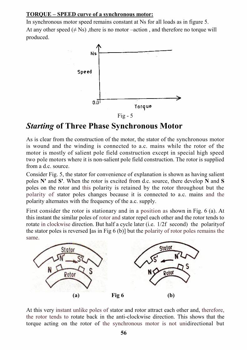
56
TORQUE – SPEED curve of a synchronous motor:
In synchronous motor speed remains constant at Ns for all loads as in figure 5.
At any other speed (≠ Ns) ,there is no motor –action , and therefore no torque will
produced.
Fig - 5
Starting of Three Phase Synchronous Motor
As is clear from the construction of the motor, the stator of the synchronous motor
is wound and the winding is connected to a.c. mains while the rotor of the
motor is mostly of salient pole field construction except in special high speed
two pole motors where it is non-salient pole field construction. The rotor is supplied
from a d.c. source.
Consider Fig. 5, the stator for convenience of explanation is shown as having salient
poles N' and S'. When the rotor is excited from d.c. source, there develop N and S
poles on the rotor and this polarity is retained by the rotor throughout but the
polarity of stator poles changes because it is connected to a.c. mains and the
polarity alternates with the frequency of the a.c. supply.
First consider the rotor is stationary and in a position as shown in Fig. 6 (a). At
this instant the similar poles of rotor and stator repel each other and the rotor tends to
rotate in clockwise direction. But half a cycle later (i.e. 1/2f second) the polarityof
the stator poles is reversed [as in Fig 6 (b)] but the polarity of rotor poles remains the
same.
(a) Fig 6 (b)
At this very instant unlike poles of stator and rotor attract each other and, therefore,
the rotor tends to rotate back in the anti-clockwise direction. This shows that the
torque acting on the rotor of the synchronous motor is not unidirectional but

57
pulsating one. It is because of inertia of the rotor, it will not move in any
direction. That is why the synchronous motor is not self-starting one.
Now let the rotor (which is yet unexcited) is speeded up to synchronous or
near synchronous speed by some external arrangement and then it is excited
through the d.c. source. The moment the rotor running at nearly
synchronous speed is excited, it is magnetically locked into position with
the stator poles which runs synchronously and that both in the same
direction. Because of this interlocking between the rotor and stator poles, the
synchronous motor has either to run synchronously or not at all.
Methods of Starting Synchronous Motors
Since the three phase synchronous motor has no starting torque,so artificial
means must be provided for starting it as below:
1. External source. If the d.c. field of a synchronous motor is supplied by a
direct-connected exciter, this exciter can be used as a starting motor. This
method is now rarely used.
2. Induction-motor start. If a squirrel cage winding is constructed in the pole
faces of the synchronous motor (damper bars), it can be used to develop a
starting torque (as well as provide damping) similar to that of the ordinary
induction motor. As the motor reaches about 95 per cent of synchronous speed
(it is operating as an induction motor with 5 percent slip) its field is excited and the
motor pulls into step.
For such a set up, the problem of limiting the starting current without to low a value
of starting torque is met in several ways:
. (a) Auto-transformers are used which are similar in design to those employed on
induction motors. The stator is connected to the reduced voltage supply of the auto-transformer until synchronous or near synchronous speed is reached, and is then connected to the full voltage.
(b) The voltage supplied to the stator can be reduced by using a series reactors
in the supply lines. These reactors give a large voltage drop and low P.F. at
starting.
(c) Various types of rotor windings are used like double squirrel
cage, or using special bar cross-sections (T bar, L bar, or simply deep,
narrow bars) to give high skin effect to the squirrel cage and thus limit
the starting current.
(d) Multiple winding. This involves a special arrangement of stator coils
so that two or more complete windings are paralleled for normal
operation. The paralleled windings have normal values of' reactance.
If one winding is left open during starting process the resistance will
double and the leakage reactance will be greater than the normal value and
will result in a reduced current without the utilization of an auto-
starter. Switching arrangement is shown in Fig. 7.

58
(a) For starting, the short-circuited switch is open and only winding 1 is utilized
(b) The short circuiting switch closes the neutral of the second winding for parallel
operation at normal load
Fig 7 Arrangement of the double-winding synchronous motor
Synchronous Condenser
When a three phase synchronous motor is used for power factor correction with no
mechanical output (no load), it is known as a synchronous condenser. The term
'condenser' applied to device that it draws leading current as does a static
condenser. There is a considerable increase in leading kilovolt- amperes
available when the horsepower load of a synchronous motor is less than its rated
load.
The synchronous condenser is especially designed so that practically all its rated
kVA are available for p.f. correction. Because of the absence of shaft load,
the mechanical design is modified from the ordinary motor standards. Because of
the p.f. adjustment possible, the synchronous condenser is particularly applicable to
transmission line control.
The ability to control the power factor of the synchronous motor by simply
varying the excitation is of very great practical importance. The importance lies in
the fact that the motor can be operated at a leading power factor when desired,
and consequently if the remaining installation has a low power factor, the
overall. power factor for the installation can be brought close to unity.

59
Hunting and Damping of Synchronous Motor
When a synchronous motor is operating under steady-load conditions and
an additional load is suddenly applied, the developed torque is less than
that required by the load and the motor starts to slow down. A slight
reduction in speed increases the phase angle of the generated voltage
and permits more current to flow through the armature Some of the
kinetic energy of the rotating parts is given out to the load during speed
reduction . When the motor is slowing down, it cannot cease deceleration
at exactly the correct torque angle corresponding to the increased load. It
passes beyond this point, develops more than required torque, and
increases in speed. This is followed by a reduction in speed and a
repetition of the entire cycle. Such a periodic change in speed is called
hunting.
The mass of the rotating part and the 'spring effect' of the flux lines are
the necessary elements which give the rotating field structure a natural
oscillating period. If the load varies periodically with this same
frequency or some multiple of it, the tendency is for the amplitude of
these oscillations to increase cumulatively until the motor is thrown
out of step, causing corresponding current and power pulsations. The
mechanical stresses are likely to be severe, and the armature current
greatly increases when the motor leaves synchronism.
A solid pole gives a damping action but has the disadvantage of
excessive pole-face losses unless closed slots are used on the armature.
The most satisfactory arrangement from the standpoint of simplicity
seems to be laminated poles with the squirrel-cage 'amortisseur' or
damping winding. The effectiveness of damper depends upon its
resistance and to a lesser extent upon the length of the airgap. A low
resistance damping winding produces the stronger effect, but if the
synchronous motor is to be started by induction-motor action, using
this squirrel cage, the winding resistance should be fairly high to
produce good starting torque. Because of these opposing tendencies, a
compromise usually must be reached in damping winding design.

60
SHEET 5
SOLVED EXAMPLES IN SYNCHRONOUS MACHINES
Example 1 :
Calculate the percent voltage regulation for a three-phase wye-connected 2500 kVA
6600-V turboalternator operating at full-load and 0.8 power factor lagging. The per
phase synchronous reactance and the armature resistance are 10.4 Ω and 0.071 Ω,
respectively?
Solution:
Clearly, we have XS >> Ra, The phasor diagram for the lagging power factor
neglecting the effect of Ra is shown in Fig. (a). The numerical values are as follows:
Vt = 6600 / √3 = 3810 V
Ia = ( 2500 * 1000 ) / ( √3 * 6600) = 218.7 A
Eo = 3810 + 218.7( 0.8 – j 0.6) j10.4 = 5485∟19.3º
Percentage regulation = ( 5485 – 3810 )/ 3810 *100 = 44%
Example 2 :
Repeat Ex.1 calculations with 0.8 power factor leading as shown in Fig. (b) ?
Solution:
Eo = 3810 + 218.7( 0.8 + j 0.6) j10.4 = 3048∟36.6º
Percentage regulation = ( 3048 – 3810 )/ 3810 *100 = -20%
Fff
H.W. : Repeat Ex.1 calculations with unity power factor , and draw the phasor
diagram for this case ?

61
Example 3 :
A 20-KVA, 220 V, 60 Hz, way-connected three phase salient-pole synchronous
generated supplies rated load at 0.707 lagging power factor.The phase constants of
the machine are Ra = 0.5 Ω and Xd =2 Xq = 4 Ω. Calculate the voltage regulation at
the specified load. ?
Solution:
Vt = 220 / √3 = 127 V
Ia = 20000 / (√3 * 220) = 52.5 A
φ = cos-1
0.707 = 45º
tan δ = (Ia Xq cos φ) / (Vt + Ia Xq sin φ)
= 52.5 * 2 * 0.707 / ( 127 * 52.5 * 2 * 0.707)
= 0.37
δ = 20.6º
Id = 52.5 sin ( 20.6 + 45 ) = 47.5 A
Id Xd = 47.5 * 4 = 190 V
Eo = Vt cos δ + Id Xd = 127 cos 20.6 + 190 = 308 V
Percent regulation = (Eo – Vt ) / Vt *100%
= ( 308 – 127 ) / 127 *100%
= 142 %
Example 4: The stator core of a 4-pole, 3-phase a.c. machine has 36 slots. It carries a short pitch 3-phase winding with coil span equal to 8 slots. Determine the distribution and coil pitch factors?
Solution:
Number of slots per pole = 36 / 4 = 9
Angular displacement between slots = β = 180º / 9 = 20º
Coil span = 20º * 8 =160º

62
Therefore, pitch factor = kp = cos (θ/2) , θ = 180º – 160º = 20º
kp = cos 10º = 0.985
Now, number of slots per pole per phase,
m = 9 /3 = 3
Distribution factor,
kd = ( Length of long chord ) / (Sum of lengths of short chords )
= [sin (mβ/2)] / [m sin (β/2)]
= sin 30º / (3 sin 10º) = 0.96
Example 5:
3- phase, 50 Hz generator has 120 turns per phase. The flux per pole is 0.07 weber, assume sinusoidally distributed. Find (a) the e.m f. generated per phase. (b) e.m.f. between the line terminals with star connection. Assume full pitch winding and distribution factor equal to 0.96 ?
Solution:
(a) E.m.f. generated per phase = 4 kf kp k d f T Φp volts
= 4 * 1.11 * 0.96 * 1 * 0.07 * 50 * 120
=1792 volts
(b) E.m.f. between line terminals= √ 3 E.m.f. generated per phase =√ 3 * 1792
= 3100 volts
Example 6:
A three phase, 16-pole, star-connected alternator, has 192 stator slots with eight conductors per slot and the conductors of each phase are connected in series. The coil span is 150 electrical degrees. Determine the phase and line voltages if the machine runs at 375 r.p m. and the flux per pole is 64 mWb distributed sinusoidally over the pole?
Solution:
The flux is sinusoidally distributed over the pole, hence from factor, kf = 1.11
Pitch factor , kp = cos [(180º - 150º) / 2 ] = cos 15º = 0.966
Distribution factor, kd = [sin (mβ/2)] / [m sin (β/2)]
m = Number of slots per pole per phase = 192 / (16 * 3) = 4
β = 180º / (No. of slots/pole) = 180º / (192/16) = 15º

63
kd = [ sin (4 * 15º / 2)] / [4 * sin (15º/2)] = sin 30º / (4 * sin 7.5º) = 0.958
Now total number of conductors per phase
=Total number of slots per phase * number of conductors per slot.
= ( 192 / 3 ) * 8 = 512
Number of turns per phase = T = 512 / 2 = 256
Frequency of generated e.m.f. = f = P N / 120
=[ Number of poles * Synchronous Speed] / 120
=[ 16 * 375] / 120 = 50 cycle per second
Flux per pole = Φp=0.064 wb
Therefore, e.m.f. per phase = 4 kf kp k d f T Φp volts
= 4 * 1.11 * 0.966 * 0.958 * 0.064 * 50 * 256
= 3367 volts
Hence for star connected alternator, Line voltage = √3 * 3367 = 5830 volts
Example 7:
A 2200 volt, star-connected, 50 cycle alternator has 12 poles. The stator has 108 slots each with 5 conductors per slot. Calculate the necessary flux per pole to give 2200 volts on no-load. The winding is concentric and the value of kf can be taken as
1.11 ?
Solution:
Slots per phase = 108 / 3 = 36
Therefore, conductors per phase = 36 * 5 = 180
and number of turns per phase = 180 / 2 = 90
Slots per pole per phase = 36 / 12 =12
Frequency, f =50 cycle per second
kf = 1.11
kp= 1.0 for concentric winding

64
kd = [sin (mβ/2)] / [m sin (β/2)]
Where β = 180º / (No. Of slots/pole) = 180º / (108/12) = 20º
m = Number of voltage vectors= Number of slots per pole per phase
= 108 / (12*3) = 3
kd = [sin (3*20º/2)] / [ 3 sin (20º/2)] = [sin 30º] / [3 sin 10º] = 0.96
Also e.m.f. per phase = Eph = 2200 /√3 volts
The e.m.f. equation for Alternator is
Eph = 4 kf kp k d f T Φp volts
Φp = Flux per pole = Eph / [4 kf kp k d f T ] =( 2200 /√3) / [ 4*1.11*1*0.96*50*90]
= 0.066 wb
Example 8: Find the number of armature conductors in series per phase required for the armature of a 3 phase, 50 Hz, 10 pole alternator with 90 slots. The winding is to be star connected to give a line voltage of 11,000 volts. The flux per pole is 0.16
webers?
Solution:
Number of slots per pole = 90 / 10 = 9
Therefore, β = 180º / 9 = 20º
Slots per pole per phase, m = 9 / 3 = 3
Distribution factor, kd = [sin (mβ/2)] / [m sin (β/2)]
kd = [sin (3*20º/2)] / [ 3 sin (20º/2)] = [sin 30º] / [3 sin 10º] = 0.96
Since there is no mention about the type of winding, the full pitched winding is assumed.
Hence , kp = 1.0
Also , Eph = 11000 / √3 = 6352 volts.
Now , Eph = 4 kf kp k d f T Φp volts
T = [Eph] / [4 kf kp k d f Φp]
= [6352] / [4 * 1.11 * 0.96 * 1 * 0.16 * 50]
= 1863
Number of Armature conductors in serues per phase = 1863 * 2 = 3726
65
Example 9 :
A six-pole, 3-phase, 60 cycle alternator has 12 slots per pole and 4 conductors per slot. The winding is 5/6 th pitched. There is 0.025 wb flux entering the armature from each north pole and the flux is sinusoidally distributed along the air gap. The armature coils are all connected in series. The winding is star-
connected. Determine the open circuit e.m.f of the alternatorper phase?
Solution:
Here, number of conductors connected in series per phase
=12 * 6 * 4 / 3 = 96
Therefore, number of turns per phase , T = 96 / 2 = 48
Flux per pole , Φp = 0.025 wb
Frequency, f =50 cycle per second .
kf = 1.11
kp = cos [180º(1 – 5/6) / 2] = cos 15º = 0.966.
Number of slots per pole per phase, m = 12 / 3 = 4
β = 180º / 12 = 15º
Distribution factor ,
kd = [sin (mβ/2)] / [m sin (β/2)]
kd = [sin (4*15º/2)] / [ 4 sin (15º/2)] = [sin 30º] / [4 sin 7.5º] = 0.958
Hence induced e.m.f.,
Eph = 4 kf kp k d f T Φp volts
= 4 * 1.11 * 0.966 * 0.958 * 0.025 * 50 * 48
= 295 volts.