internal fault detection in padmounted distribution transformers western underground committee fall...
TRANSCRIPT

Internal Fault Detection in Padmounted Distribution Transformers
Western Underground Committee
Fall Meeting – 9/26/12Paul Henault – IFD Corporation

Presentation Outline An overview of distribution transformer faults
Current industry issues and practices
Options for improvement
Questions
Common Utility Goals
Improve safety for line workers
Reduce outage times
Improve system reliability
Improve asset utilization
Prepare for the workforce of the future

What does an internal transformer fault look like?
A rapid, transient pressure rise occurs in every internal arcing fault
Variable peak pressure
Consistent rate of rise

What does an internal transformer fault look like?
Certification tests at Powertech Labs
500A test
Arc Voltage
Fault Current
Pressure Rise
IFD activates before peak
~ 3 psi

Why internal fault detection is important
Linemen Safety Operating challenges Crew pressures Risk every time we re-close
Troubleshooting Effectiveness Speed Accuracy
System Reliability Reduce outage times SAIDI/SAIFI

Why is internal fault detection important?
Linemen Safety Operating challenges Crew pressures Risk every time we re-close
Troubleshooting Effectiveness Speed Accuracy
System Reliability Reduce outage times SAIDI/SAIFI

Potential Costs Due to Unidentified Faulted Transformers
Safety & Environmental
Long outage times
SAIDI/SAIFI
Removing unfaulted transformers from service
Cost of troubleshooting tools

Causes of padmounted transformer fuse operations
Secondary Faults
Overloads
Oil Temperature (Dual Element Fuse)
Internal Transformer Faults

Internal Faults in Padmounted Transformers are usually not obvious externally
Current Industry Practices
1) Automatic Replacement2) Field Testing3) Trial & Error

Automatic Replacement
Most of the time the transformer is OK
Expensive and time consuming to remove the transformer, transport it to the shop, test it, and return it to service

Portable Field Testers*
“Testers are expensive and not every vehicle has them”
“They often don’t detect low grade transformer faults at the voltages that they generate”
“I no longer use it because it kept indicating unfaulted transformers, but when I reenergized them, they often were faulted”
*Lineman feedback

Trial and Error
1. Visual examination2. Manual checks,
PRV “Sniff…don’t inhale”
3. Attempt to reclose on transformer
“Push and pray” “Now, crawl inside your
helmet” “Go get the new guy"

What about PRV’s?
PRV operation:P > 10±2 psi ≠ Internal fault
(Poppet style PRV) ‘does not have time to react to the overpressure rates of rise and values produced when low-impedance faults occur.’ A. Even et al., “Safety of Distribution Transformers against internal failure”,
Conference Publication No. 438., IEEE, 1997

Product Development Co-Sponsors
National Research Council
Utilities: BC Hydro Hydro Quebec Manitoba Hydro Others
Transformer Manufacturers
Technical specs
Fault testing
Field testing
Certification
Financial support
Product value

Application Requirements
1) Primary function: Reliable detection of internal arcing faults
>0.5 psi/5-7ms transient internal pressure [± 500 amps]
High visibility Easy to install Maintenance free No effect on transformer Etc…
2) Also: Incorporate pressure relief valve in design

The Purpose
To give electric utility employees the information they need to troubleshoot and restore power to distribution transformers faster, safer, and more
economically than they used to.

1) Always wear the appropriate personal protective equipment including fire retardant clothing, hard hats, safety glasses and rubber gloves.
2) When performing any close inspections of or repairs to the transformer always deenergize the unit and take precautions from any sources of power including customer generators.
3) Prior to re-fusing transformers, make a thorough inspection of the transformer and the surrounding area, looking for indicators such as: animal carcasses, bulged tank or cover, discolored tank, oil leak, burned oil aroma, flashed or broken bushings, any short circuits such as wrapped wires in the secondary or service.
4) Prior to re-fusing transformers, test the transformer with an approved instrument such as a Transformer Turns Ratio tester. Some companies require some form of testing on every transformer before they are energized.
5) When re-fusing a suspected faulty transformer, position yourself as far away as possible by using an extendable live line tool. Some companies specify maintaining a distance of at least 10 ft. when re-fusing transformers.
6) When re-fusing a suspected faulty transformer, always disconnect the customer’s load. 7) Test the transformer with a smaller test fuse. (Some companies have test fuse tables
based on the transformer size and voltage). 8) If the transformer blows a fuse and the pressure relieve valve has operated, do not re-fuse
and proceed with replacement. 9) If the transformer has an auxiliary current limiting fuse that has blown, do not re-fuse;
proceed with replacement. Checking transformer condition 10) Maintain proper distance when re-fusing. In this condition: do not refuse 11) Always make sure the neutral is connected first before connecting a transformer and that it
is removed last if disconnecting a transformer. 12) Do not allow the paralleling of transformers across any point that might be used to isolate a
line section, such as switches, disconnects and double dead ends to avoid the possibility of back feed into a cleared line section.
13) Always wear rubber gloves when working on the secondary side of a suspected faulty transformer.
14) Take precautions when removing the lid from a suspected faulty transformer by operating the pressure relief valve. If it is an older unit without a valve, tie a sling over the lid before loosing the attachments.
15) Some companies have established step-by-step procedures for investigating transformer problems while others allow the lineworker to access the situation and take precautions they deem necessary within mandatory safety guidelines.
16) It is recommended that step-by-step procedures be developed as they are good training aids and can serve as a refresher for lineworkers. They also help ensure certain key steps are followed
Look At the Transformer
Complex troubleshooting procedures
OR

One-Size-Fits All

How it works
Fault occursRapid
pressure rise
IFD activates
3


Application Notes
Expulsion Fuses
Expulsion Fuses with Isolation Links
Expulsion Fuses with Current Limiting Fuses
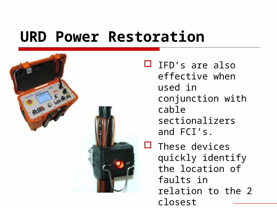
URD Power Restoration
IFD’s are also effective when used in conjunction with cable sectionalizers and FCI’s.
These devices quickly identify the location of faults in relation to the 2 closest transformers.
The IFD indicates whether the fault is in either of those 2 transformers, or external to them.

Improve linemen safety
Enable faster and more accurate troubleshooting, and reduce outage times
Keep unfaulted units in service
Prepare for the next generation of linemen
The Goals –
Use visual internal fault indication to:

Thank you…questions?