interchangevs 3000 series vs3000u and vs3000s · 2020-05-27 · email: [email protected] ftp...
TRANSCRIPT
™
InterChangeVS 3000 SeriesVS3000U and VS3000S
Installation and ConfigurationGuide
Copyright © 1997, 1998. Comtrol Corporation. All Rights Reserved.Second Edition, March 3, 1998Comtrol Corporation makes no representations or warranties with regard to the contents of this guide or to the suitability of Comtrol products for any particular purpose. Specifications subject to change without notice. Some software or features may not be available at the time of publication. Contact your reseller for current product information.
TrademarksComtrol and InterChangeVS are trademarks of Comtrol Corporation.Microsoft and Windows NT are registered trademarks of Microsoft Corporation.Novell and NetWare are registered trademarks and MultiProtocol Router, IntranetWare, and NetWare Connect are trademarks of Novell, Inc.Citrix and WinFrame are registered trademarks of Citrix Systems, Inc.Other product names mentioned herein may be trademarks and/or registered trademarks of their respective companies.
Corporate Corporate Headquarters:Internet URL: www.comtrol.comemail: [email protected] site: ftp.comtrol.comFAX: (612) 631-8117
Phone: (612) 631-7654Comtrol Europe:Internet URL: www.comtrol.co.ukemail: [email protected]: +44 (0) 1 869-323-211Phone: +44 (0) 1 869-323-220Comtrol has a staff of software and hardware engineers, and technicians available to help you.
Document Part Number: 6620D
Table of Contents
List of Tables ........................................................................................ 5
Introduction ......................................................................................... 7Product Overview ................................................................................... 7
Features ............................................................................................ 7ISDN Service Standards Supported................................................ 8Operating System Requirements .................................................... 8Connectivity Requirements ............................................................. 8
Installation Overview ............................................................................. 9Backup Server Overview ...................................................................... 10
Backup Server Configuration and Hierarchy ............................... 10Distributing the Workload ............................................................. 10Returning Control to the Primary Server..................................... 11
Software or Document Updates ........................................................... 12Comtrol Corporate Headquarters.................................................. 12Comtrol Europe .............................................................................. 12
Installing VS-Link (Windows NT).................................................. 13
3
Removing Existing VS-Link Software ................................................. 13Installing the VS-Link Software .......................................................... 14
Extracting the Files........................................................................ 14Software Installation...................................................................... 15Primary and Backup Servers Explained....................................... 22Installing Additional Virtual Servers ........................................... 22Changing SPIDs ............................................................................. 23
Installing and Configuring RAS .......................................................... 24Replacing Units in Service (“Hot-Swapping”) ..................................... 34

Table of Contents
Troubleshooting ................................................................................ 35Problem Resolution Checklist .............................................................. 35
Understanding the Ethernet LEDs............................................... 36Understanding the Port LEDs....................................................... 37
Obtaining Software and Document Updates....................................... 38Placing a Support Call.......................................................................... 38
Comtrol Corporate Headquarters.................................................. 40Comtrol Europe .............................................................................. 40
ISDN Cause Codes............................................................................. 41
Index..................................................................................................... 49
4

List of Tables
Table 1. Ethernet LED Descriptions ..................................................36Table 2. Port LED Descriptions ..........................................................37Table 3. Support Call Information......................................................38Table 4. ISDN Cause Codes ................................................................41
5

List of Tables
6

Introduction
Product Overview
The Comtrol™ InterChangeVS™ 3000 virtual remote access server is a rack-mountable or stackable “network appliance” that connects via Ethernet to a host Windows NT® or Novell® NetWare® server and terminates four Basic Rate Interface (BRI) ISDN lines. Each ISDN line (“port”) consists of two 64 Kbps B channels and one 16 Kbps D channel: each B channel can be used independently, for up to eight simultaneous 64 Kbps connections, or the B channels can be bonded, for connections of up to 512 Kbps. This bandwidth, along with the flexible data compression schemes that are supported, makes the VS3000 ideal for site-to-site file transfers and graphics-intensive Internet/intranet applications.
Features
• Supports both ISDN Datalink Layer ITU-T Q.921 and ITU-T Q.931 D-channel signaling.
• Supports both North American (VS3000U) and international (VS3000S) users with the same product family and software.
• Provides the performance and features of a standalone remote access
Product Overview 7
server with reduced implementation and operating costs.• Automatic backup server switching ensures that ISDN services stay
available even if the primary server goes down.• “Hot-swapping” lets you take VS3000 units in or out of service
without downing the server or interrupting other network services.• VS-Link software gives you direct and immediate control of the
VS3000, including monitoring and diagnostic functions.• Full support for Windows NT RAS, Novell NetWare MultiProtocol
Router™, and Novell NetWare Connect™ functionality.
Introduction
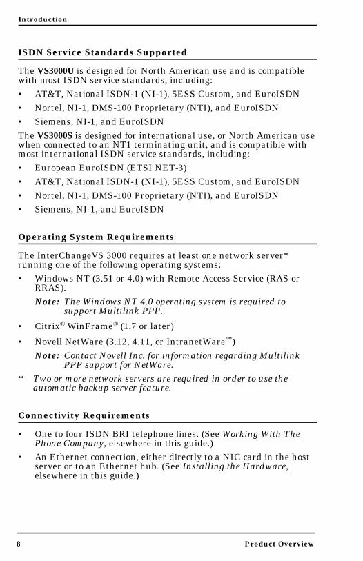
ISDN Service Standards Supported
The VS3000U is designed for North American use and is compatible with most ISDN service standards, including: • AT&T, National ISDN-1 (NI-1), 5ESS Custom, and EuroISDN• Nortel, NI-1, DMS-100 Proprietary (NTI), and EuroISDN• Siemens, NI-1, and EuroISDNThe VS3000S is designed for international use, or North American use when connected to an NT1 terminating unit, and is compatible with most international ISDN service standards, including:• European EuroISDN (ETSI NET-3)• AT&T, National ISDN-1 (NI-1), 5ESS Custom, and EuroISDN• Nortel, NI-1, DMS-100 Proprietary (NTI), and EuroISDN• Siemens, NI-1, and EuroISDN
Operating System Requirements
The InterChangeVS 3000 requires at least one network server* running one of the following operating systems:• Windows NT (3.51 or 4.0) with Remote Access Service (RAS or
RRAS).Note: The Windows NT 4.0 operating system is required to
support Multilink PPP.
• Citrix® WinFrame® (1.7 or later)
• Novell NetWare (3.12, 4.11, or IntranetWare™)
8 Product Overview
Note: Contact Novell Inc. for information regarding Multilink PPP support for NetWare.
* Two or more network servers are required in order to use the automatic backup server feature.
Connectivity Requirements
• One to four ISDN BRI telephone lines. (See Working With The Phone Company, elsewhere in this guide.)
• An Ethernet connection, either directly to a NIC card in the host server or to an Ethernet hub. (See Installing the Hardware, elsewhere in this guide.)

Introduction
Installation Overview
The following figure illustrates the InterChangeVS 3000 hardware and software installation procedure.Note: The following procedure assumes that the ISDN line is already
installed and operational. See the Working with the Phone Company section for more information.
To install VS-Link the
Install the VS3000 using theInstalling the Hardware section.
Connect an RJ45 ISDN* cable between theVS3000 and ISDN line phone jack or NT1
first time, use the software installation section for your
operating system.
To update VS-Link or addadditional VS3000 units,
remove the existing VS-Link.
Connect the appropriate Ethernet* cablebetween the VS3000 and the network.
Terminating Unit (depending on country).
Installation Overview 9
Re-install VS-Link using thesoftware installation sectionfor your operating system.
While ISDN and Ethernet cables may appear to be identical, they are not interchangeable. Make sure you are using the correct cable(s) in the correct locations.
*

Introduction
Backup Server Overview
Both the Windows NT and Novell versions of VS-Link support automatic backup server switching. If you have more than one NT or Novell server on a network, you can configure one server as the primary server for the VS3000, and one or more other servers as backup servers for the same VS3000.Once configured, primary-to-backup server switching is automatic. In the event that the primary server goes offline, the backup server waits the amount of time you specified during setup. If the primary server does not come back online in that time, the backup server automatically resets the VS3000 (in the process terminating any calls in progress), then reloads the VS3000 using the configuration information stored on the backup server and restores ISDN service.
Backup Server Configuration and Hierarchy
To configure backup server operation, you must install the VS-Link software on the primary server and on every server that may be used as a backup server. Then, when you configure the software on a given server, you follow these steps:1. Select the specific VS3000 to be controlled by this server.2. Select whether this server is the primary or backup server for the
selected VS3000.3. If a backup server, select the amount of time the server waits
(Recover Time in Windows NT, Polling Time in Novell) before taking over from the primary server.
Each VS3000 must have one and only one primary server, but it can multiple backup servers. Thus, by configuring each potential backup
10 Backup Server Overview
server with a different recover time, you can establish a hierarchy that determines which backup server to go to, and when.
Distributing the Workload
Note that primary/backup server configuration is set for each VS3000 on the network individually. This means that a given server can be the primary server for some of the VS3000 units on the network, and the backup server for others. For example, in the following illustration, server “A” is the primary server for VS3000-1 and the backup server for VS3000-2, while server “B” is the primary server for VS3000-2 and the backup server for VS3000-1. Thus, the normal workload is distributed between the two servers, but if one of them goes down, the other takes over support of both VS3000 units.

Introduction
Note: VS-Link for Novell can support four VS3000 units (either primary, backup, or mixed) per Novell server. VS-Link for Windows NT can support thirty-two VS3000 units per NT server.
Returning Control to the Primary Server
When the primary server comes back online after a service outage, backup-to-primary switching is not automatic. Instead, you must go to the primary server and perform a manual procedure to reassert control over the VS3000.On Windows NT networks, access the ISDN Monitor program and use
Server
Server
VS3000-1
VS3000-2“B”
“A”
Primary
Backup
Primary
Backup
Backup Server Overview 11
the Reset option.On Novell networks, load the vs3kcfg.nlm utility and use the Primary, Force Load option.

Introduction
Software or Document Updates
For information that is not in this Guide, see README and/or Help files on the installation media. In particular, the Windows NT version of VS-Link and the Windows NT ISDN Monitor program include significant online help.Comtrol manuals and other documents are available in electronic form on the Comtrol web site. Driver software updates can be downloaded at no charge from the Comtrol ftp site. Always check the web and ftp sites to make sure that you have the current driver and documentation.The current released version of the software is stored in the VS3000 directory. If a newer version has reached the beta testing stage, it can be found in the BETA directory. Beta software is made available on an “as-is” basis and users of beta software assume all risks and liabilities relating thereto.Note: Downloadable driver software files are stored in either zipped
(filename.zip) or self-extracting zip (filename.exe) format. You must extract the zipped files before installing a downloaded file. For more information, see the appropriate section for your network operating system.
Comtrol Corporate Headquarters
Internet URL: www.comtrol.comemail: [email protected] site: ftp.comtrol.comFAX: (612) 631-8117
12 Software or Document Updates
Phone: (612) 631-7654
Comtrol Europe
Internet URL: www.comtrol.co.ukemail: [email protected]: +44 (0) 1 869-323-211Phone: +44 (0) 1 869-323-220

Installing VS-Link (Windows NT)
Removing Existing VS-Link Software
Use the following procedure to remove any existing VS-Link software. If updating (not reconfiguring) VS-Link, make sure that you remove the existing version before installing the updated software.1. Open the Control Panel and start the Network applet, or right-click
on the Network Neighborhood and select the Properties option.2. If using Windows NT 4.0, select the Adapters tab.
Removing Existing VS-Link Software 13
3. Highlight Comtrol InterChangeVS(TM)-3000.4. Click the Remove button.
Installing VS-Link (Windows NT)
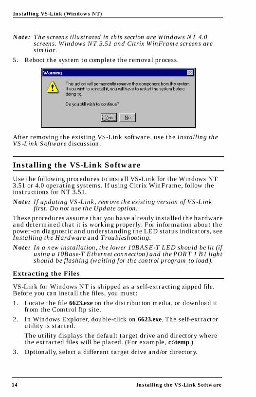
Note: The screens illustrated in this section are Windows NT 4.0 screens. Windows NT 3.51 and Citrix WinFrame screens are similar.
5. Reboot the system to complete the removal process.
After removing the existing VS-Link software, use the Installing the VS-Link Software discussion.
Installing the VS-Link Software
Use the following procedures to install VS-Link for the Windows NT 3.51 or 4.0 operating systems. If using Citrix WinFrame, follow the instructions for NT 3.51.Note: If updating VS-Link, remove the existing version of VS-Link
first. Do not use the Update option.These procedures assume that you have already installed the hardware and determined that it is working properly. For information about the power-on diagnostic and understanding the LED status indicators, see Installing the Hardware and Troubleshooting.
14 Installing the VS-Link Software
Note: In a new installation, the lower 10BASE-T LED should be lit (if using a 10Base-T Ethernet connection) and the PORT 1 B1 light should be flashing (waiting for the control program to load).
Extracting the Files
VS-Link for Windows NT is shipped as a self-extracting zipped file. Before you can install the files, you must:1. Locate the file 6623.exe on the distribution media, or download it
from the Comtrol ftp site.2. In Windows Explorer, double-click on 6623.exe. The self-extractor
utility is started.The utility displays the default target drive and directory where the extracted files will be placed. (For example, c:\temp.)
3. Optionally, select a different target drive and/or directory.

Installing VS-Link (Windows NT)
4. Click the Unzip button.The self-extractor utility creates a directory named \WinNT on the target drive and directory and places the extracted VS-Link files in that directory. For example, if you use the default target directory c:\temp, then the extracted files are placed in c:\temp\WinNT .When the process is finished, a message is displayed, and you may close the self-extractor utility.
Software Installation
After you have extracted the VS-Link files, follow these steps:1. Open the Control Panel and start the Network applet, or right-click
on the Network Neighborhood and select Properties.The Network Properties window is displayed:
Installing the VS-Link Software 15

Installing VS-Link (Windows NT)
2. If Windows NT 4.0 select the Adapters tab and click the Add button. If Windows NT 3.51, select the Add Adapter button.
16 Installing the VS-Link Software

Installing VS-Link (Windows NT)
3. If Windows NT 4.0, select the Have Disk button. If Windows NT 3.51, scroll down to the bottom of the list, highlight the Other option, and select the Continue button.
4. If installing from a diskette, insert the diskette in the drive.5. Enter the drive and directory path to the installation files and
click the Ok button.
Installing the VS-Link Software 17
For example, if you used the self-extractor utility to create a c:\temp\winnt directory, enter:
c:\temp\winnt
Installing VS-Link (Windows NT)
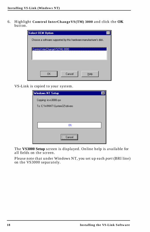
6. Highlight Comtrol InterChangeVS(TM) 3000 and click the OK button.
VS-Link is copied to your system.
18 Installing the VS-Link Software
The VS3000 Setup screen is displayed. Online help is available for all fields on the screen.Please note that under Windows NT, you set up each port (BRI line) on the VS3000 separately.

Installing VS-Link (Windows NT)
Installing the VS-Link Software 19
7. Select the port number that you want to configure and press the Tab key.Note: If installing only one BRI line, it must be PORT 1.
8. Use the droplist to select the Central Office Network Type, and press the Tab key.
9. If necessary, enter the Primary SPID (up to 14 numerical, decimal digits) and press the Tab key.Note: When entering SPIDs and directories, do not enter any
dashes or spaces. The SPID, SPID suffix, and TID are often required in North American installations.

Installing VS-Link (Windows NT)
10. If necessary, fill in or verify the Primary Directory Number. The Directory Number is the 7-digit “local phone” number, not the phone number to which you plan on calling.
Note: If you entered a SPID number and pressed the Tab key, VS-Link automatically inserts the Directory Number.
20 Installing the VS-Link Software
11. Press the Tab key to move to the Secondary SPID field.12. Optionally, enter the Secondary SPID and press the Tab key.13. Verify the Secondary Directory Number, or change it if needed.14. Press the Tab key to move to the Network (MAC) Address field.15. Enter the remainder of the MAC address (Network Address).
Press the Tab key between fields.

Installing VS-Link (Windows NT)
16. If setting up more than one port on this VS3000, repeat Steps 7 through 13 for each additional port. Use the Tab and Shift-Tab keys to move between entry fields.
17. If using this NT server as the primary server for this VS3000, leave the Backup Server checkbox empty and skip to step 18.If using this NT server as the backup server for this VS3000 (in a multiple server network), click the Backup Server checkbox. Then use the Recover Time droplist to select the recovery time.Note: For more information about backup servers, see “Primary
and Backup Servers Explained,” later in this chapter.18. After all of the ports have been configured, click the OK button.
Installing the VS-Link Software 21

Installing VS-Link (Windows NT)
19. If Windows NT 4.0, select the Close button from the Network applet. If Windows NT 3.51, select the Continue button from the Network applet.
20. Reboot the server so that your changes take effect.To complete installation, use the Installing and Configuring RAS subsection to configure remote access services for the VS3000.
Primary and Backup Servers Explained
Once configured, primary-to-backup server switching is automatic. In the event that the primary NT server goes offline, the backup server waits the amount of time specified in the Recover Time. If the primary NT server does not come back online in that time, the backup server resets the VS3000 (in the process terminating any calls in progress), then reloads the VS3000 using the configuration information set up on the backup server.Thus, the backup server configuration must have the same MAC address as the primary server, and should have the same port, network, SPID, and directory information as the primary server. However, this is not required. It is also possible to set up several backup servers, each with different recover times, for the same VS3000, but each VS3000 must have only one primary server.
22 Installing the VS-Link Software
When the primary server comes back online after an outage, backup-to-primary switching is not automatic. Instead, use the ISDN Monitor program on the primary server to manually reassert control over the VS3000 and reload it with the configuration stored on the primary server, in the process terminating any calls in progress.For more information regarding primary and backup servers, see the VS3000 Setup and ISDN Monitor online help files.
Installing Additional Virtual Servers
Follow these steps to add another VS3000 to an existing Windows NT server VS3000 installation.1. Follow steps 1—6 in the Software Installation subsection. At step
6, a message appears indicating that an adapter of this type is already installed.
Installing VS-Link (Windows NT)
2. Click OK to continue. The VS3000 Setup window is displayed.3. Enter the setup information for the new VS3000. Do not use the
same Network Address or SPIDs as any previously installed unit.4. Click the OK button to save your changes and exit this window.5. Reboot the server so that the new VS3000 is recognized.6. Use the Installing and Configuring RAS subsection to finish
configuring the new VS3000 for use with RAS.
Changing SPIDs
1. To change SPID or Directory numbers, you must access the VS3000 Setup program. There are four ways to do this:• From the Start button menu, select Programs, Comtrol
InterChange VS3000, Setup for VS3000. (There will be a separate listing for each VS3000 configured on this server.)
• In the ISDN Monitor program, select the VS3000 to work with, then click the Setup button.
• From the desktop, right-click on the Network Neighborhood icon and select Properties. The Network applet is launched.
• From the Control Panel, select the Network applet.2. The first two options take you straight to setup. If you use the
Network applet instead, click on the Adapter tab, then select InterChangeVS(TM)-3000 and click the Configure button. The VS3000 Setup window displays.
3. Use the droplist to select the affected port.4. Make the desired changes.
Installing the VS-Link Software 23
5. Click OK to save your changes and exit setup.6. If necessary, exit the Network applet.Your changes take effect immediately. You do not need to reboot the server.It is also possible to change the network (MAC) address—for example, if it was entered incorrectly, or if you are replacing a VS3000 with another one. For more information, see Replacing Units in Service (“Hot-Swapping”), later in this chapter.

Installing VS-Link (Windows NT)
Installing and Configuring RAS
If you have not previously installed RAS or RRAS in your Windows NT server, use the following procedure.Note: You must be logged on to the Windows NT computer with
Administrative rights to perform any of these tasks.1. Open the Control Panel and start the Network applet, or right-click
on the Network Neighborhood and select Properties.• If installing RAS or RRAS, go to Step 2.Note: RRAS installation and configuration is similar to RAS.
These screens illustrate RAS; see RRAS documentation if you need help.
• If configuring the VS3000 in an existing RAS environment, go to Step 5.
Note: The screens illustrated in this section are Windows NT 4.0 screens. Windows NT 3.51 screens are similar.
The following screen appears:
24 Installing and Configuring RAS

Installing VS-Link (Windows NT)
2. If Windows NT 3.51, highlight the Remote Access Service from the list and select the Add Software button. If Windows NT 4.0, select the Services tab and click the Add button.
Installing and Configuring RAS 25

Installing VS-Link (Windows NT)
The following screen appears:
3. Highlight the Remote Access Service option and click the Ok button.
26 Installing and Configuring RAS
4. Enter the location of the Window NT files and press the Continue button. For example: d:\i386.

Installing VS-Link (Windows NT)
The appropriate files are loaded on to your hard drive.
5. Select the ISDN1 - ICVS3000 from the drop-down list of RAS Capable Devices and press the Ok button.
Installing and Configuring RAS 27

Installing VS-Link (Windows NT)
6. With the ISDN - ICVS3000 highlighted, click the Configure button.
7. Select the appropriate radio button based on the role this port of the VS3000 will perform and press the OK button.
28 Installing and Configuring RAS
Installing VS-Link (Windows NT)
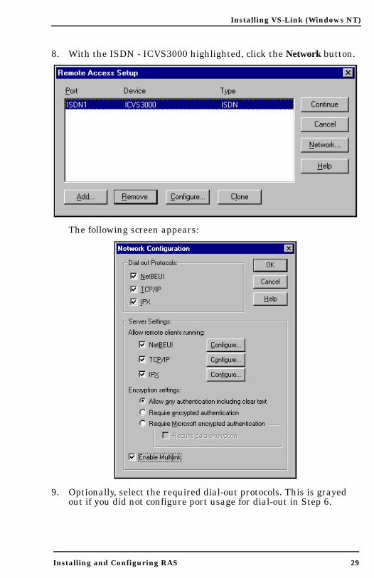
8. With the ISDN - ICVS3000 highlighted, click the Network button.
The following screen appears:
Installing and Configuring RAS 29
9. Optionally, select the required dial-out protocols. This is grayed out if you did not configure port usage for dial-out in Step 6.
Installing VS-Link (Windows NT)
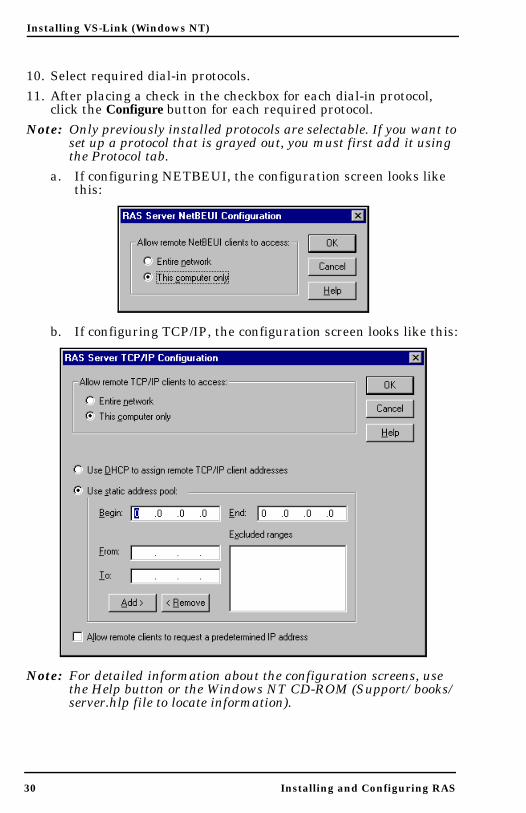
10. Select required dial-in protocols. 11. After placing a check in the checkbox for each dial-in protocol,
click the Configure button for each required protocol.Note: Only previously installed protocols are selectable. If you want to
set up a protocol that is grayed out, you must first add it using the Protocol tab.
a. If configuring NETBEUI, the configuration screen looks like this:
b. If configuring TCP/IP, the configuration screen looks like this:
30 Installing and Configuring RAS
Note: For detailed information about the configuration screens, use the Help button or the Windows NT CD-ROM (Support/books/server.hlp file to locate information).

Installing VS-Link (Windows NT)
c. If configuring IPX, the screen looks like this:
12. Select the authentication encryption levels for this port.
Installing and Configuring RAS 31
13. Optionally, select Enable Multilink if you want to bond channels.Note: The Windows NT 3.51 operating system does not support
Multilink PPP. To use Multilink PPP (bonding) with Windows NT 4.0, make sure that you check the Multilink PPP checkbox in the RAS Setup screen.

Installing VS-Link (Windows NT)
14. After completing the Network Configuration screen, click the OK key. The Remote Access Setup window is displayed again:
15. Select the Add button to configure additional ports on the VS3000. Repeat Steps 4 through 7 of this procedure to configure each port.
Note: Every ISDN Basic Rate Interface (BRI) line consists of two channels called B1 and B2. Each channel corresponds to a port description in Remote Access Service (RAS). In RAS, the ports are referred to as ISDN1, ISDN2, and so on. Therefore, when four ISDN BRI lines are installed, there are eight channels, and you must add and configure eight RAS ISDN ports.
The illustration below is an example only. Actual assignment of B channels to RAS ISDN ports is made dynamically by the central office. For example, sometimes B2 is assigned to ISDN1.
32 Installing and Configuring RAS
BRI Line 1 B1B2B1B2Line 2
Line 3
Line 4
Channel
Installing VS-Link (Windows NT)
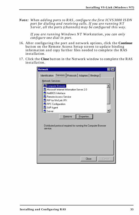
Note: When adding ports to RAS, configure the first ICVS3000 ISDN port for dialing and receiving calls. If you are running NT Server, all the ports (channels) may be configured this way.
If you are running Windows NT Workstation, you can only configure one dial in port.
16. After configuring the port and network options, click the Continue button on the Remote Access Setup screen to update binding information and copy further files needed to complete the RAS installation.
17. Click the Close button in the Network window to complete the RAS installation.
Installing and Configuring RAS 33

Installing VS-Link (Windows NT)
18. Click the Yes button when asked to reboot the computer.
Replacing Units in Service (“Hot-Swapping”)
In the event that a VS3000 needs to be removed from service, it is possible to replace it with another VS3000 without taking down the NT server. To do so, follow this procedure:1. Connect the replacement VS3000 to power and Ethernet and verify
that it passes the power-on diagnostics.2. Terminate any calls in progress.3. From the Comtrol program group, select ISDN Monitor .4. If you have more than one VS3000 already in service, use the Open
Device option on the Device menu to select the VS3000 you want to swap out.
5. In the ISDN Monitor program, click the Setup button to launch the VS3000 Setup program. The Setup window is displayed.
6. Verify that the Network Address (MAC) shown is the address of the VS3000 you are taking out of service.
34 Replacing Units in Service (“Hot-Swapping”)
7. Enter the Network Address of the replacement VS3000.8. Enter any other configuration changes needed at this time.9. If you are using more than one port, repeat steps 6 through 8 for
each port in use.10. Click OK to save your changes, close the setup program, and
return to the ISDN Monitor program.11. Swap the ISDN cables from the old VS3000 to the replacement
VS3000, if needed.12. Click the Reset button to reinitialize VS-Link.13. Power down the VS3000 you are removing from service and
disconnect it from the network.You may now resume normal operations.

Troubleshooting
This section discusses the following topics:• Isolating and resolving problems• Understanding the LED displays• Obtaining software and/or document updates• Placing a call to Comtrol Technical Support
Problem Resolution Checklist
If installation fails or the VS3000 does not operate as expected, try the following before calling the Comtrol technical support line:• Check for proper cable connections. In particular, check to make
sure that you have an Ethernet cable on the Ethernet port and ISDN cables on the ISDN ports. The two types of cables are easy to swap by accident.
• Turn the VS3000 on and off and watch for errors on the LEDs using the Understanding the LEDs subsections. (These are found on the following pages.)
• Check the VS-Link software to make sure that the Network Address (MAC) in the software matches the Network Address on the VS3000.
Problem Resolution Checklist 35
• Verify that you have the correct model (VS3000U or VS3000S) for your locale. The VS3000U is for North American use only. The VS3000S is for international use, but requires an NT1 terminating unit. For more information see Installing the Hardware.
• If you are operating in a multiple-server environment, check to make sure that you are controlling the VS3000 from its primary server, that there is only one primary server assigned to this particular VS3000, and that no backup server has pre-empted the primary server.Note: Backup-to-primary switching is not automatic. Once a
backup server takes over control of a VS3000, you must follow a manual procedure to restore control to the primary server. This procedure differs depending on your network operating system. See the chapter for your operating system for more information.

Troubleshooting
• If you are operating in a multiple-server environment and a backup server has taken over control of the VS3000, check (if possible) to make sure the backup server has the same Port, SPID, Directory Number, and MAC configuration as the primary server.
• If this is a Windows NT installation, use the ISDN Monitor program to trace and log the messages being passed between the NT server and the VS3000. Use the ISDN Cause Codes section of this manual to interpret the results. Also note that other error messages may be displayed in the Event Log.
• If this is a Novell installation, use the vs3kcfg.nlm utility to trace and log the messages between passed between the server and the VS3000. Use the ISDN Cause Codes section of this manual to interpret the results. Also note that other error messages may be displayed in the Console Log.
• If you have more than one VS3000, follow the Replacing Units in Service procedure for your operating system to “hot-swap” VS3000 units. If this corrects the problem, the VS3000 you have removed from service may be defective or need repair.
• When all else fails, remove and reinstall the VS-Link software.
Understanding the Ethernet LEDs
The following table describes Ethernet LED activity for the VS3000.
36 Problem Resolution Checklist
Table 1. Ethernet LED Descriptions
LED Indicator Description
10Base-T (Upper) Flashing Flashes briefly during transmissions from the
unit as a general indicator of activity.
10Base-T (Lower) On VS3000 is correctly attached to the LAN by the
RJ45 10Base-T connector.
10Base-T (Lower) Off Connected to the AUI connector or the 10Base-T
connection is not connected to the LAN properly.

Troubleshooting
Understanding the Port LEDs
The following table describes PORT LED activity after:• VS-Link is installed and configured.• Operating system configuration is completed for the VS3000.
Table 2. Port LED Descriptions
Port LEDs Status Description
B1 or B2
Off Normal standby state - no calls pending or established.
Flashing
B1 or B2 selected for a call, but not yet connected. A call has been initiated and the CO has assigned the B1 or B2 channel as the channel that the call will connect on. If the call connects normally, this state may not even be seen because the connection happens so fast.
On Call connected on B1 or B2.
Off
Line disconnected or failed. Bad Line; layer 1 not up. This can occur if the VS3000 is not connected to the CO, or if there are hardware or software
Problem Resolution Checklist 37
D
problems preventing synchronization with the CO.
Flashing
Equipment failed or not configured properly. Bad SPID; layer 1 is activated, but Layer 2 is not up yet. Layer 2 is the LAPD layer that ensures a reliable data path to the CO. In Layer 2 there is polling going on between the CO and hardware all the time. This state could indicate configuration problems.
OnNormal activity. The VS3000 is ready for use; layer 1 and 2 are up. In this state, both B channels are available for use.

Troubleshooting
Obtaining Software and Document Updates
For information that is not in this guide, see README and/or Help files on the installation media. In particular, the Windows NT version of VS-Link and the Windows NT ISDN Monitor program include significant online help.Comtrol manuals are available in electronic form on the Comtrol web site. VS-Link software and manual updates can be downloaded at no charge from the Comtrol ftp site. Always check the web and ftp sites to make sure that you have the current software and documentation.The current released version of the software is stored in the VS3000 directory. If a newer version has reached the beta testing stage, it can be found in the BETA directory. Beta software is made available on an “as-is” basis and users of beta software assume all risks and liabilities relating thereto.Note: Downloadable driver software files are stored in either zipped
(filename.zip) or self-extracting zip (filename.exe) format. You must extract the zipped files and create an installation diskette before installing a downloaded file. For more information, see the appropriate section for your network operating system.
Placing a Support Call
Before you call Comtrol technical support, please have the following information available. (Much of this information should already be in the ISDN Software Installation Information table in the Working With The Phone Company section of this guide.)
Table 3. Support Call Information
38 Obtaining Software and Document Updates
Item Value
Operating System type and release number
VS-Link release number
Computer make and model
ISDN Installation Typeo EZ-ISDN1o 2B+D (without EKTS)o Other____________________
ISDN Line Type o BRI
ISDN Help Desk Phone Number
Circuit ID

Troubleshooting
Switch Vendor (hardware type)o ATT 5ESSo Nortel DMS-100o Siemens (EuroISDN)
Network Type (software)
o National ISDN1 (NI-1)o ATT Customo DMS-100 Proprietary (NI-1)o EuroISDN (NET3)
Windows NT Novell
Por
t 1
Primary SPID* SPID 1*
Primary Directory Number**
Directory Number** 1
Secondary SPID SPID 2
Secondary Directory Number
Directory Number 2
Por
t 2
Primary SPID SPID 3
Primary Directory Number
Directory Number 3
Secondary SPID SPID 4
Secondary Directory Number
Directory Number 4
Primary SPID SPID 5
Table 3. Support Call Information
Item Value
Placing a Support Call 39
Por
t 3
Primary Directory Number
Directory Number 5
Secondary SPID SPID 6
Secondary Directory Number
Directory Number 6
Por
t 4
Primary SPID SPID 7
Primary Directory Number
Directory Number 7
Secondary SPID SPID 8
Secondary Directory Number
Directory Number 8

Troubleshooting
* The SPID (Service Provide Identifier) is an up-to-14-digit number resembling a telephone number and consisting of the SPID, SPID suffix, and TID. In some cases, your phone company may also provide you with an ISDN sub-address for each SPID. SPIDs are required for North American installations only.
** The Directory Number (also known as the ISDN directory number or ISDN address) is the 7-digit “local phone number” portion of the SPID.
After you have gathered this information, contact Comtrol:
Comtrol Corporate Headquarters
Internet URL: www.comtrol.comemail: [email protected] site: ftp.comtrol.comFAX: (612) 631-8117Phone: (612) 631-7654
Comtrol Europe
Internet URL: www.comtrol.co.ukemail: [email protected]: +44 (0) 1 869-323-211Phone: +44 (0) 1 869-323-220
40 Placing a Support Call
ISDN Cause Codes
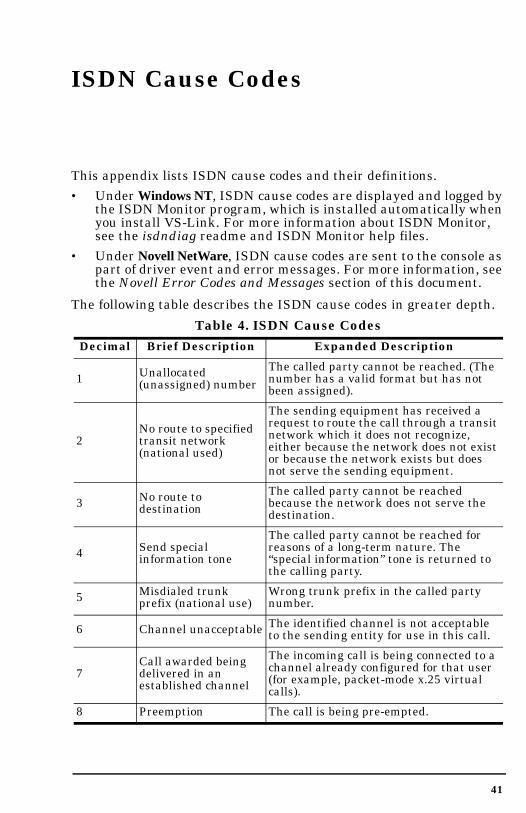
This appendix lists ISDN cause codes and their definitions.• Under Windows NT, ISDN cause codes are displayed and logged by
the ISDN Monitor program, which is installed automatically when you install VS-Link. For more information about ISDN Monitor, see the isdndiag readme and ISDN Monitor help files.
• Under Novell NetWare, ISDN cause codes are sent to the console as part of driver event and error messages. For more information, see the Novell Error Codes and Messages section of this document.
The following table describes the ISDN cause codes in greater depth.
Table 4. ISDN Cause Codes Decimal Brief Description Expanded Description
1 Unallocated (unassigned) number
The called party cannot be reached. (The number has a valid format but has not been assigned).
2No route to specified transit network (national used)
The sending equipment has received a request to route the call through a transit network which it does not recognize, either because the network does not exist or because the network exists but does not serve the sending equipment.
No route to The called party cannot be reached
41
3 destination because the network does not serve the destination.
4 Send special information tone
The called party cannot be reached for reasons of a long-term nature. The “special information” tone is returned to the calling party.
5 Misdialed trunk prefix (national use)
Wrong trunk prefix in the called party number.
6 Channel unacceptable The identified channel is not acceptable to the sending entity for use in this call.
7Call awarded being delivered in an established channel
The incoming call is being connected to a channel already configured for that user (for example, packet-mode x.25 virtual calls).
8 Preemption The call is being pre-empted.

ISDN Cause Codes
9 Preemption (circuit reserved for reuse)
The call is being pre-empted and the circuit is reserved for reuse by the pre-empting exchange.
16 Normal call clearingThe call is being cleared because one of the users participating in the call has requested that the call be cleared.
17 User busy
The called party is unable to accept another call because the user busy condition has been encountered (by the called user or by the network). If the user is busy, it is noted that the user equipment is compatible with the call.
18 No user respondingThe called party does not respond to a call establishment message with either an alerting or connect indication within the allocated time period.
19 No answer from user(User alerted)
The called party has been alerted but does not respond with a connect indication within the allocated time period. This is not necessarily generated by Q.931 procedures but may be generated by internal network timers.
20 Subscriber absent
A mobile station has logged off, radio contact is not obtained with a mobile station, or a personal telecommunications user is temporarily not addressable at any user-network interface.
The equipment sending does not accept
Table 4. ISDN Cause Codes (Continued)Decimal Brief Description Expanded Description
42
21 Call rejectedthis call. The equipment is neither busy nor incompatible. This can be generated by the network, indicating that the call was cleared by a supplementary service constraint.
22 Number changedThe called-party number is no longer assigned. The new called-party number may be included in the diagnostic field.
26 Non-selected user clearing
The user has not been awarded the incoming call.
27 Destination out of order
The destination cannot be reached because the interface to the destination is not functioning. A signal message was not delivered to the remote party because of a physical layer or data link layer failure at the remote party, or the user equipment is off-line.

ISDN Cause Codes
28Invalid number format (address incomplete)
The called party cannot be reached because the called number is not in a valid format or is not complete.
29 Facilities rejected A requested supplementary service cannot be provided by the network.
30 Response to STATUS INQUIRY
This is a confirmation of the receipt of a STATUS INQUIRY.
31 Normal, unspecified No other normal-class cause applies.
34 No circuit/channel available
There is no appropriate circuit/channel presently available to handle the call.
35 Call queued The call has been queued at the central office (CO).
38 Network out of orderThe network is not functioning for reasons of a long-term nature. Immediately re-placing the call is not likely to be successful.
39Permanent frame mode connection out-of-service
Included in a STATUS message, indicating a permanently established frame mode connection is out-of-service due to equipment or section failure.
40Permanent frame mode connection operational
The STATUS message indicates a permanently established frame mode connection is operational and capable of carrying user information.
41 Temporary failureThe network is not functioning for reasons of a short-term nature. You may attempt another call almost immediately.
Table 4. ISDN Cause Codes (Continued)Decimal Brief Description Expanded Description
43
42 Switching equipment congestion
The switching equipment generating this cause is experiencing a period of high traffic.
43 Access information discarded
The network could not deliver access information to the remote user as requested. That is, user-to-user information, low layer compatibility, high layer compatibility, or sub-address as indicated in the diagnostic.
44 Requested circuit/channel not available
The circuit or channel indicated by the requesting entity cannot be provided by the other side of the interface.
46 Precedence call blocked
There are no pre-emptable circuits or the called user is busy with a call of equal or higher pre-emptable level.

ISDN Cause Codes
47 Resource unavailable —unspecified
No other cause in the resource- unavailable class applies.
49 Quality of Service not available
The requested Quality of Service, as defined in the X.213 Recommendation cannot be provided (that is, throughput of transit delay cannot be supported).
50 Requested facility not subscribed
The user has requested a supplementary service which is implemented but which the user is not authorized to use. Wrong SPID.
52 Outgoing calls barred Administratively prohibited calls.
53 Outgoing calls barred within CUG
The calling party is a member of the Closed User Group for the outgoing CUG call, but outgoing calls are not allowed for this member.
54 Incoming calls barred No incoming calls possible; for example, a pay phone.
55 Incoming calls barred within CUG
The calling party is a member of the Closed User Group for the incoming CUG call, incoming calls are not allowed for this member.
57 Bearer capability not authorized
The user is not authorized to use the requested B channel.
58 Bearer capability not presently available
The user has requested an unavailable B channel.
Inconsistency in Inconsistency in the designated outgoing
Table 4. ISDN Cause Codes (Continued)Decimal Brief Description Expanded Description
44
62 outgoing information element. access information and subscriber class.
63 Service or option not available, unspecified
No other service- or option-not-available cause code applies.
65 Bearer capability not implemented
The sending equipment does not support the requested B channel.
66 Channel type not implemented
The sending equipment does not support the requested channel type.
69 Requested facility not implemented
The sending equipment does not support the requested supplementary services.
70
Only restricted digital information bearer capability is available (national use)
The calling party requested an unrestricted B channel (UDI @ 64kbps) service but the sending equipment only supports the restricted (RDI @ 56kbps) B channel version.

ISDN Cause Codes
79Service or option not implemented, unspecified
No other service- or option-not-available cause code applies.
81 Invalid call reference value
The sending equipment has received a message with a call reference not currently in use on the user-network interface.
82 Identified channel does not exist
The sending equipment has received a request to use a channel not activated on the interface for a call. For example, if a user has subscribed to those channels on a primary rate interface numbered from l to 12 and the user equipment or the network attempts to use channels 13 through 23.
83A suspended call exists, but this call identity does not
A call-resume has been attempted with a call identity that differs from that in use for any presently suspended call(s).
84 Call identity in useThe network has received a call-suspended request containing a call identity (including the null call identity) that is already in use.
85 No call suspendedThe network has received a call-resume request containing a call identity element that does not indicate any suspended call within the domain of interfaces.
Call having the The network has received a call-resume request containing a call identity information element indicating a
Table 4. ISDN Cause Codes (Continued)Decimal Brief Description Expanded Description
45
86 requested call identity has been cleared suspended call that has in the meantime
been cleared while suspended; either by the network time-out or the remote user.
87 User not a member of CUG
The called user for the incoming Closed User Group call is not a member of the specified CUG or the calling user is an ordinary subscriber calling a CUG subscriber.
88 Incompatible destination
The sending equipment has received a request to establish a call that has low/high layer compatibility or other compatibility attributes (for example, data rate) that cannot be accommodated. Another possibility is sending a DISPLAY to a station with no display feature.
90 Non-existent CUG The specified CUG does not exist.

ISDN Cause Codes
91Invalid transit network selection (national use)
The transit network identification is in an incorrect format as defined in Annex C/Q.931.
95 Invalid message, unspecified
No other invalid-message cause code applies.
96Mandatory information element is missing
The information element is wrong. Typically, the switch software type has been defined incorrectly.
97*Message type non-existent or not implemented
The sending equipment has received a message with a message type it does not recognize. Either this message is not defined or defined but not implemented.
98*Message not compatible with call state or message type non-existent
The sending equipment received a message such that the procedures do not indicate that this is a permissible message to receive while in the call state, or a STATUS message was received indicating an incompatible call state.
99*Information element/parameter non-existent or not implemented
The sending equipment received a message that includes information elements or parameters not recognized. The information was discarded. The information element is not required to be present in the message in order for the sending equipment to process the message.
The sending equipment received an information element that it has
Table 4. ISDN Cause Codes (Continued)Decimal Brief Description Expanded Description
46
100* Invalid information element contents
implemented; however, one or more fields in the I.E. are coded but not implemented. Usually indicates a wrong switch type in customer premises equipment.
101Message not compatible with call state
A message has been received that is incompatible with the call state.
102 Recovery on timer expire
A procedure has been initiated by the termination of a timer in association with error handling procedures.

ISDN Cause Codes
103Parameter non-existent or not implemented - passed on (national use)
The sending equipment received a message including parameters not recognized, either because the they are not defined or because they are defined but not implemented. The parameters were ignored—except if the equipment sending this cause is an intermediate point, in which case the parameters pass unchanged.
110Message with unrecognized parameter discarded
The sending equipment discarded a received message that includes a parameter that is not recognized.
111 Protocol error, unspecified
No other cause in the protocol error class applies.
127 Interworking, unspecified
An interworking call (usually a call to SW56 service) has ended.
* The switch is programmed wrong for Cause Codes 97 through 100.
Table 4. ISDN Cause Codes (Continued)Decimal Brief Description Expanded Description
47

ISDN Cause Codes
48

Numerics10Base-T
connector 36LEDs explanation of 36
5ESS 8
Aadding a device 27AUI port LEDs 36
BB channel
description of 7backup server 7, 10–11, 21, 22bonding channels
Novell NetWare 8Windows NT 31
BRI linesexplanation of 32in Windows NT 18
Ccables
configuringWindows NT RAS 24
DD channel
description of 7DMS-100 8
Eerrors
ISDN error codes 41LEDs 36, 37
Ethernet 36LEDs 36
ETSI NET-3 8EuroISDN 8Europe
how to contact Comtrol 40technical support 12
Hhardware
installation overview 9
Index
49
Ethernet and ISDN 9needed for installation 8shipped with VS3000 8
cause codes 41–47channel
B description of 7D description of 7
channelsbonding (Novell) 8bonding (Windows NT) 31
Citrix 8, 14Comtrol
how to contact 40
help filesISDN Monitor 38Novell 38Windows NT 22, 30, 38
hot-swapping 7, 34, 36
Iinstallation
additional units in Windows NT 22
Ethernet requirements 8extracting installation files 14flowchart 9ISDN requirements 8
Index
operating system requirements 8
overview of 9RAS 24removing VS-Link software 13VS-Link for Windows NT 14–
22Windows NT path 17
ISDN 37BRI lines explained 32cause codes 41connector 37RAS 27standards supported 8
ISDN Monitor program 22, 23, 34, 36, 41
ITU-T Q.921 7ITU-T Q.931 7
LLEDs
Ethernet explanation of 36explanation of 36ISDN explanation of 37PORT explanation of 37
M
PPORT LEDs 37power-on diagnostics 36, 37problems
resolving 35–40product
overview 7
RRAS
adding a device 27channel definition 32installation and configuration
for VS3000 24reconfiguring VS-Link
Windows NT 23Remote Access Service (RAS)
Windows NT 24removing VS-Link software 13
SSiemens 8software
how to get updates 12installation overview 9
SPID
50
MAC address 20multilink PPP
Novell NetWare 8Windows NT 4.0 8, 31
Nnetwork address (MAC) 20NI-1 8Nortel 8notices
legal 4trademark 4
NT1 terminating unit 8, 35
changing under Windows NT 23
Ttechnical support
contacting 4, 12, 38downloading driver files 38electronic user guide 38obtaining software updates 38
troubleshooting 35–40backup servers 35checklist 35downloaded driver files 12Ethernet and ISDN cables 35

Index
extracting installation files 14extracting the installation
files 12, 38hot-swapping VS3000 units 36ISDN cause codes 41ISDN Monitor program 36network address (MAC) 35Novell NetWare 36obtaining software updates 12returning control to primary
server 11swapping out units in
service 34vs3kcfg.nlm 36Windows NT 36
UU.K.
how to contact Comtrol 40technical support 12
U.S.A.technical support 12
uninstall 13updates
how to obtain 12user guide
electronic 12
Windows NTchanging SPIDs 23
WWindows NT
adding a RAS device 27backup server 21, 22bonding channels 31CD-ROM Help Files 30central office network type 19changing SPIDs 23extracting the installation
files 14hot-swapping 34installation path 17installing additional units 22installing VS-Link 14ISDN Monitor program 22network address (MAC) 20primary directory number 20primary SPID 19RAS installation and
configuration 24recover time 21removing VS-Link
software 13–14secondary directory
51
VVS3000
installing additional units in Windows NT 22
installing RAS 24product overview 7
vs3kcfg.nlm 36VS-Link
installation path (Windows NT) 17
removing the software 13
number 20secondary SPID 20software installation 14–22
WinFrame 8, 14

Index
52


Part Number: 6620D March 3, 1998