installation, maintenance, & safety instructions · 2017-06-30 · rev 06 fng install manual 6...
TRANSCRIPT

Rev 06 FNG Install Manual 1
Flip ‘N Go INSTALLATION, MAINTENANCE,
& SAFETY INSTRUCTIONS
(800) 272-6276
001-321-757-7611 www.cramarotarps.com
Plants In: Delaware, Florida, Massachusetts, Nevada, Ohio, and Canada
®
®
®

Rev 06 FNG Install Manual 2
Table of Contents
Step Description Page
Cramaro Warranty 3
Sample Installation Views 4
Step 1 Determining Placement of the System Prior to Starting 5
Step 2 Roller Plate Assembly & Installation 6
Step 3 Shields 6
Step 4 Roller Tube 7
Step 5 Trailer Header (Optional for Radius'd Fronts) 7
Step 6 Manual Drive (See Separate Installation Instructions for the Electric Drive Option) 8
Step 7 Tarp Attachment 9
Step 8 Pivot Point Placement 9
Step 9 Attaching Pivot Points to the Side of the Body 10
Step 10 Tuning the Pivot Points (Standard) 10
Step 11 Installing the Quick Mount System 10
Step 12 Spring—Arm—Elbow for Standard System 11
Step 13 Elbows and Reinforcement Braces 11
Step 14 Two Bend Elbow Installation (Standard on 10-20’ Systems, Optional on Others) 12
Step 15 Crossbar—Tarp—Rubber Bumpers 13
Step 16 Rear Arm Supports (Optional) 13
Step 17 Hold Downs (Optional) 13
Safety 14
Maintenance 14
Operating the System 14
System Drawing and Parts List 15
Adjustable Crank Drawing & Parts List 16
Important: Read before you start
1. The DOT regulated maximum width of a vehicle with a tarp system is 108”. That is 102” for the body plus 3” per side. The 3” per side is the maximum and both sides are to be equal.
2. Height limits are set by individual states and can vary from 13’6” to 14’. It is important to make sure you will be in compliance with your state & Federal rules before making any modifi-cations to your vehicle.
3. Read through these instructions and familiarize yourself with the various part of the system. Look at the various types of front roller installations in figure 1 to determine which one best typifies your vehicle
4. Never operate the tarp system under power lines or when the vehicle is moving!

Rev 06 FNG Install Manual 3
PRODUCT WARRANTY
GENERAL INFORMATION
Prior to returning any part for warranty, customers should contact Cramaro Sales at 800-272-6276 to explain the issue and obtain a Return Goods Authorization (RGA) number. Parts are returned at the customer’s expense. After a part has been deter-mined to be covered by warranty, Cramaro will ship the repaired or replaced part to the customer prepaid. Any expedited ship-ping or special handling is solely the customer’s responsibility.
Cramaro products are warranted against defects in quality and workmanship only. They are not warranted for application suita-bility or any specific application other than what they were designed for. This warranty does not cover any non-Cramaro labor to remove or replace any part found to be defective.
It is also understood that under the terms of sale that Cramaro does not assume responsibility for and is not liable for any con-sequential losses or damages to equipment or materials; or expenses incurred due to delays, loss of production, vehicle down time, loss of revenue, or costs resulting from a product failure within the limits of this warranty.
For more information contact Cramaro Sales at 800-272-6276. Please have order information and details of the claim availa-ble.
TARP SYSTEMS AND RELATED PARTS
Cramaro warrants its tarp systems and parts (excluding tarps and electrical components) to be free of defects for a period of 1 year from the date of shipment. Cramaro’s liability is limited to repair or replacement of covered items. See above for exclu-sions and exceptions. Improper installation will burn out electrical components and may damage the motor. These products should be installed by trained technicians only.
TARPS
Tarp seals and/or stitching that is found to be defective will be repaired by Cramaro. Tarps must be returned to Cramaro for repairs. Tarp fabric is not warranted as it is subject to wind damage if not used properly. Warranty coverage is for 1 year from date of shipment.
ELECTRICAL COMPONENTS
Electrical components (such as wire, breakers, switches, solenoids, relays, etc.) are not returnable nor are they covered under warranty.
ELECTRIC MOTORS
All SuperWinch motor assemblies are warranted for 3 years from date of shipment
All other motors - warranted for a period of 1 year from date of shipment. Motor assemblies must be returned intact. Any at-tempt to disassemble will void all warranties. Cramaro will repair or replace defective motors upon inspection at our discre-tion. Cramaro does not warranty motors installed on non-Cramaro systems.
PLASTIC LINERS
Liners are not warranted against wear and tear. We recommend that the “Plastic Bed Liner Usage Chart” be viewed to select the best liner for the material being transported.
FOR MORE INFORMATION CONTACT CRAMARO AT (800) 272-6276

Rev 06 FNG Install Manual 4

Rev 06 FNG Install Manual 5
Step 1: Determining Placement of System PRIOR to STARTING
IMPORTANT: THIS IS FOR PLACEMENT ONLY YOU ARE NOT INSTALLING YET.
1. Decide if you want the upper arm to rest in front of the tailgate or behind the tailgate.
2. If you plan on having the upper arm stop in front of tailgate or on top of tailgate then mark the spot where furthest point of arm will rest. Arms should be 1” (2.54 cm) above the tailgate.
3. If you plan to have the upper arm extend past the tailgate use an imaginary point 3” (7.62 cm) past tailgate as the resting point. If you are positioning the arms past the tailgate you will need to install optional rear arm supports for the arms to rest on.
4. Determine where you want to install the roll-er assembly. You may want to temporarily tack weld or clamp the roller plate where you will eventually want it to be mounted.
NOTE: DO NOT POSITION THE ROLLER PLATES TOO FAR FORWARD. THE ARMS OR GROUND CONTROL MAY PREVENT THE DRIVER’S DOOR
FROM OPENING.
Questions to Answer Before You Start
1. Is the front of the bed radius’d or chamfered? If so the optional Header Assembly will be required. This should have been ordered with the system?
2. Will you mount the pivot plates on the side of the body or under it? If they are to be mounted under the body then the optional Underbody Brackets will be required?
3. Are you going to use optional quick mount system?
4. Will you be using the 148 degree elbows to keep the arms out of the way of the loading area?
5. Do you plan to have the arms extend past the tailgate or rest on it? If they will rest beyond the tailgate optional rear arm supports, part number “FLIPSOEARS” will be required to rest the arms on?

Rev 06 FNG Install Manual 6
Step 2: Roller Plate Assembly and Installation
Step 3: Shield Installation
The roller plate assemblies should be mounted as far forward as possible on the body to keep the arms and cross-bar clear of the loading area. However do not mount them so far forward that the arms or the chain from the crank assembly might interfere with the cab doors from opening.
Mount the roller plate so the top of the roller plate is approximately 7 1/8” above the body to allow room for the tarp roll up on the roller. Keep in mind DOT height restrictions. Make certain the (2) shield mounting holes are fac-ing forward. When mounting the roller plates look at the cab shield or header to ensure square alignment in rela-tion to the box. If one side is bent a little adjust roller plate position to ensure the roller is mounted square to the box.
Important: If the final roller assembly is not square to the box the tarp might not retract evenly and cause prema-ture wear and damage to the tarp
The shield is used to block wind from blowing under the tarp and minimize wind whip.
1. Bolt shield adaptors to the roller plates using 3/8” x 1” bolts, flat washers, and nylon lock nut.
2. Mount the shield to the adaptors using 3/8” x 1” bolts, flat washers, and lock nuts.
3. Overlap the shields together until the desired width is achieved. Drill through both shields at the (4) pre-drilled holes in the middle and bolt shields together using (4) 3/8” x 1” bolt, flat washer, and nylock nut. (The head of the bolts should be on the inside of the shield).
1. To mount the roller plates, weld or drill (2) holes to the outside of cab shield and fasten with (2) 3/8” x 1 1/4” bolts, (4) flat washers and nylon lock nuts.
2. The roller plates should be at the same width as the maximum width of the outside of the body. Fabrication may be required if the cab shield is narrower than the outside of the body or if the back of the body is wider than the front.
3. Using the 3/8” x 1 1/4” bolts mount the bear-ing to the outside of the passenger side roller plate. The bolt head and washer should be on the inside of the plate and the nut against the bearing.
4. If you will be installing shields please continue with the instructions below. If you are using the optional trailer header for radius’d fronts, please skip the shields section and proceed to Step 5.

Rev 06 FNG Install Manual 7
Right Side Shown
This option is used when the trailer has a radius front. The header enables you to mount the roller plate assembly further forward, which gives you more “loading” area, and less likely to get arms damaged when loading. On square fronts the header can be used for faster, easier assembly.
Step 4: Roller Tube Installation
Step 5: Trailer Header Installation (Optional for Radius’d Fronts)
1. Determine the center point of outside of trailer width.
2. Center the header at the front.
3. Make sure the header will be high enough to allow clearance for the tarp to wind on to the roller tube. Then, bolt the header to the front of trailer using (4) 1/2" X 4” course bolts, (8) 1/2" flat washers, and (4) 1/2" nylockk nuts. Modifi-cations or the use of spacer plates (not sup-plied) may be required.
1. Measure the distance between the inside to inside of the roller plate assemblies.
2. Deduct 1/2” from the distance and cut the excess off the end of the aluminum roller tube that does not have the pre-drilled hole. This should allow a 1/4” ‘gap’ on driver side and a 1/4” ‘gap’ on the passenger side when the roller is in place.
3. Position the roller tube between the plates and slide the 6” roller end through the passenger side bearing and roller plate into the roller. From the outside, Insert the ¾” x 6” steel shaft into the ¾” side bearing until flush with collar side and tighten the 2 set screws holding it in place.
4. If you purchased a manual crank unit, mount (1) ¾” cast iron bearing to the outside of the driver’s side roller plate. Bolt using (2) 3/8” X 1 1/4” bolts, (2) 3/8” flat washers, and (2) 3/8” nylock nuts.

Rev 06 FNG Install Manual 8
Step 6: Manual Drive Installation (If you are installing the Electric Drive refer to separate instructions)
Important: Do not position the roller plates so far forward that they interfere with driver’s door.
1. Drill a 3/8'' hole through the slot on both sides and front of the top box. Make certain the hole is in the top of the slot to facilitate tightening of the chain in a later process.
2. Temporarily bolt the sections together using 3/8'' x 1'' bolts, flat washer and nylon lock nut. Position the two side bolts with the head of the bolt on the inside, nuts on the outside. Position the front bolt with the head of the bolt on the outside, and nut on the inside. Release the clamps.
3. Take the top box lid off if needed to facilitate looping the chain around the top sprocket and bottom sprocket. Cut off any excess chain to reach the desired length and connect with the master link provided. Make certain to position master link in the position shown. Once the chain is together properly, tighten the chain by extending the two telescoping boxes by loosen-ing the (3) bolts and retighten. The chain should not have more than 3/4'' (19.05 mm) play from side to side. Replace the top box lid. CAUTION: the lower handle has 2 sprockets the smaller inside one is for the chain.
4. Slide the upper crank box shaft through the driver side bearing and into the roller tube until the bearing on crank unit and bearing on the roller plate meet. Tighten the set screws on the roller plate bearing.
5. Fasten the crank box to the body with the brackets attached to the box by drilling 11/32” hole and fastening with 3/8” x 1” self-tapping bolts with 3/8” lock washers. Make sure the chain is not binding.
6. If using the manual crank unit: Space the end of the roller tube 1/2” (12.7 mm) from the in-side of the driver side roller plate. Using the pre-drilled pilot hole on the roller tube, drill a 5/16” hole through the ¾” shaft on the crank unit and bolt through using 5/16” x 2 ½” bolt, flat washer and 5/16” nylon lock nut. If using the electric motor option: line up the pre-drilled hole in the roller tube and the hole in the shaft on the motor and bolt through using the 5/16” x 2 ½” bolt, flat washer and 5/16” nylon lock
When using the adjustable crank unit you will need to determine what length you need the assembly to be. The distance from shaft on the crank unit when it is positioned in the roller assembly, down to where you want the crank handle placed for easy cranking. The crank unit must be installed perpendicular to the roller tube. As such, a mounting surface may have to be fabricated.
Lay the handle assembly on the floor or a stable work surface. Extend the unit to the desired length. Temporarily clamp the unit together so it cannot extend or retract.

Rev 06 FNG Install Manual 9
Step 7: Tarp Attachment
Step 8: Pivot Point Placement
To attach the tarp, slide the plastic spline into the slotted extrusion of the roller tube. Use the “access slot” to feed half of the tarp in first, then feeding the other half in and centering the tarp.
You may additionally attach the tarp to the roller tube by using ¼” x ¾” bolts and washers, not included. You should use at least 5 bolts. Make sure the holes in the tarp are behind the spline to prevent them from tearing loose.
The pivot point is the center of the shaft on the pivot plate.
Determine the pivot point for arm assembly. Your pivot point will be the same distance from the roller assembly at front as from its rear resting point.
If the body is 96” or less, arms must have 2” (5.08 cm) of clearance between inside of arm and widest point of body along swing path of arms while arms are parallel to each other.
Do not permanently install springs, arms, etc. at this time. This illustra-tion is used to show if the pivot points need to be spaced out from the side of the body.

Rev 06 FNG Install Manual 10
Step 9: Attaching Pivot Points to the Side of the Body
Step 10: Tuning the Pivot Points (Standard)
BRACKET OR GUSSET
SIDE SIDE
LEFT RIGHT
PIVOT POINT
1. If the body is greater than 96” or installing a 31’ or greater, this set up or underbody mount with offset pivot arms is re-quired. Installation of pivot plates may require the fabrication of custom brackets or gussets (not supplied). These brackets may be necessary so that the pivot plates are mounted out from the body to achieve the 1” (2.54cm) of clearance for the lower arms. Gussets must be welded to insure that the pivot plate has no vertical movement.
2. Use 3/8” x 1 ¼” bolts, flat washer and nylon lock nut to mount pivot plates to the brackets. Use the hole configuration shown by dark circles.
Once mounted, test the pivot bracket for proper alignment by placing the lower arm over the steel pivot arm then onto the pivot shaft without the spring. Simulate the path of the lower arm back and forth. The distance between inside of arm and the body should be the same from front to rear. If it is not check to make sure the pivot brackets are mounted flush and not at an angle. If that is not the problem you can 'tune' the pivot bracket (do not 'tune' the arm). Place a sturdy piece of pipe over the shaft and gently bend the shaft to the desired loca-tion. Make certain not to compromise the integrity of the pivot bracket.
Step 11: Installing the Quick Mount System 1. Mount the preassembled pivot assembly (including the aluminum plate, bearing and angle bracket with tube,
hex bar and spring) to the side of the truck bed, with the bearing facing out. The assembly should mount with the plate against the outside and the angle bracket against the underside. To mount use (2) ½” x 1 ½” bolts, lock washer, nut and (4) flat washers
2. To mount angle bracket underneath use (2) 3/8” x 1” “F” point screw and lock washer.
3. Slide (2) 1” flat washers onto the hex bar.
4. Slide a lower pivot arm onto the hex bar so it is facing the rear of the truck with the plate on the arm to the outside.
5. NOTE: When doing this, the lower pivot arm should be facing downward at approximately a 20-degree angle and with no tension applied to the spring. Once on, when lifting the arm higher, there should be resistance from the spring. This is crucial in order to create proper tension on the spring when the arms are in place.
6. Once the pivot arm is on, slide a 1” flat washer on and insert a ¼” x 1 ¾” roll pin into the hex bar.
7. Pull the pivot arm out until it contacts the washer/ roll pin and tighten the setscrew.
Rear of the Truck->
Rev 06 FNG Install Manual 11
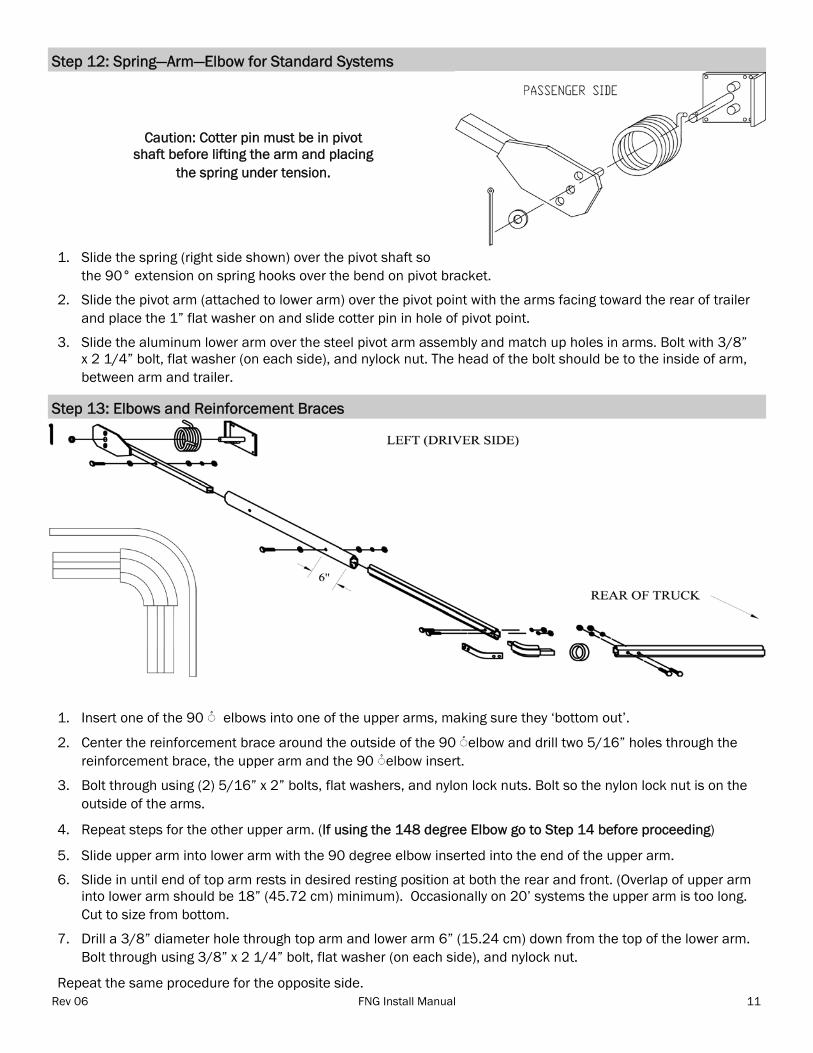
Step 12: Spring—Arm—Elbow for Standard Systems
Step 13: Elbows and Reinforcement Braces
1. Slide the spring (right side shown) over the pivot shaft so the 90° extension on spring hooks over the bend on pivot bracket.
2. Slide the pivot arm (attached to lower arm) over the pivot point with the arms facing toward the rear of trailer and place the 1” flat washer on and slide cotter pin in hole of pivot point.
3. Slide the aluminum lower arm over the steel pivot arm assembly and match up holes in arms. Bolt with 3/8” x 2 1/4” bolt, flat washer (on each side), and nylock nut. The head of the bolt should be to the inside of arm, between arm and trailer.
Caution: Cotter pin must be in pivot shaft before lifting the arm and placing
the spring under tension.
1. Insert one of the 90 ْ◌ elbows into one of the upper arms, making sure they ‘bottom out’.
2. Center the reinforcement brace around the outside of the 90 ْ◌ elbow and drill two 5/16” holes through the reinforcement brace, the upper arm and the 90 ْ◌ elbow insert.
3. Bolt through using (2) 5/16” x 2” bolts, flat washers, and nylon lock nuts. Bolt so the nylon lock nut is on the outside of the arms.
4. Repeat steps for the other upper arm. (If using the 148 degree Elbow go to Step 14 before proceeding)
5. Slide upper arm into lower arm with the 90 degree elbow inserted into the end of the upper arm.
6. Slide in until end of top arm rests in desired resting position at both the rear and front. (Overlap of upper arm into lower arm should be 18” (45.72 cm) minimum). Occasionally on 20’ systems the upper arm is too long. Cut to size from bottom.
7. Drill a 3/8” diameter hole through top arm and lower arm 6” (15.24 cm) down from the top of the lower arm. Bolt through using 3/8” x 2 1/4” bolt, flat washer (on each side), and nylock nut.
Repeat the same procedure for the opposite side.

Rev 06 FNG Install Manual 12
Step 14: Two Bend Elbow Installation (Standard on 10-20’ Systems; Optional on Others)
This option is used to utilize the full loading capacity and to get the upper arms out of the loading area, thus pro-tecting the arms from damage.
1. Determine where you want to insert elbow. The minimum closest point from the end of the upper arm and “cut” for placement of elbow is 6” (15.24 cm).
2. Cut the upper arm straight across where you want to insert elbow and smooth the cut rough edges, inside and out.
3. Insert the elbow into the straight piece of the upper arm.
4. Slide top piece of upper arm over other insert of elbow. (Be sure that bend on the upper arm is bent upwards when the arms are at the front of the truck.)
5. Center elbow reinforcement over the junction on the outside of the arms. Clamp on both sides to prepare for drilling bolt holes.
6. Drill through arm and insert of elbow – bolt using 5/16” x 2” course bolts, 5/16” flat washers, and 5/16” ny-lock nuts.
7. Build the left side with the elbows opposite to the right side
8. Return to: Step 13 item 5

Rev 06 FNG Install Manual 13

Rev 06 FNG Install Manual 14
Step 15: Cross Bar—Tarp—Rubber Bumpers
Step 16: Rear Arm Supports (Optional)
Step 17: Hold Downs (Optional)
For the proper cut length of the crossbar; make sure the arms are parallel to each other.
1. Measure the distance between the elbows; make sure the measurement includes the distance once ‘bottomed out’. Against the elbow, cut the crossbar to the desired length. Smooth edges inside and out for easy insertion.
2. Take the crossbar and slide through pocket in tarp.
3. Place a Rubber Bumper on each end of the crossbar before attaching the crossbar to the elbows and assem-bling to the upper arms. Slide in the Bumpers so they are resting on the tailgate or the top rails and to the outside of the tarps’ grommet tabs. To get optimum use of these bumpers, the crossbar should rest on top of the tailgate.
4. Once the tarp and bumpers are inserted, connect the crossbar to the elbows. Drill 5/16” holes through the reinforcement brace, the crossbar and the 90 ◌ْelbow. Bolt through using (2) 5/16” x 2” bolts, flat washers, and nylon lock nuts. Bolt from underneath, so the nylon lock nut is on the outside of the arms. With washers on the head of the bolt, tighten all bolts securely.
5. Repeat connection of crossbar to the other side.
6. Center tarp on crossbar and drill 9/32” diameter hole through the two grommet tabs then fasten with 5/16” x 1” self- tapping screws with 5/16” lock washers and 5/16” flat washers.
7. Make sure to spread the cotter pin at pivot point open both ways and grease the fitting.
1. Typically used when extending the crossbar past the tailgate
2. Install ears with 3/8” x 5 1/2” bolts provided, at an angle to match resting position desired. You may need to build out from the trailer for the ears to be lined up with the arms.
Hold downs are used to prevent “wind whip”. They are used with vinyl tarps and longer tarps . Vinyl tarps will not be warranted when hold downs are not used.
1. Unless a special order is made, cables come 3’ long. Measure first to make sure that the cable and the strap are long enough to connect properly. Distances vary with positioning and body heights.
2. Drill through the upper arm approximately 12” down from the 90 degree elbow (or 6” below 148 degree el-bow if they are being utilized).
3. Fasten the 5/16” x 2” eyebolt through the hole with the eyelet on the outside of arm, using a 5/16” flat washer, lock washer and nut.
4. Mount the ratchet with 24” strap straight below the eyelet at the bottom of the trailer. Use the 3/8” x 1” self-tappers to fasten the ratchet holder. There are to be mounted at the front and back of the body on both sides with the tarp and arms in the fully “covered” and fully uncovered positions.

Rev 06 FNG Install Manual 15
Safety
Maintenance
Operating the System
1. When installing your system, use OSHA approved ladders or scaffolding when working above ground level
2. Be careful of existing wires in or on the truck bed
3. Disconnect battery terminals before doing any welding.
4. Use “helpers” when necessary to hold or help lift.
5. Keep clothing and body parts clear of any moving parts while operating system.
6. Vinyl tarps are required to be secured at rear in windy conditions.
7. Do not dump with load covered.
8. When operating system, BEWARE OF OVERHEAD WIRES.
9. When operating system, make sure there is no one in the swing path of the arms.
1. Perform the following every week for the first month after installation, then monthly thereafter:
2. Grease pivot points on lower arms
3. Grease bearings on roller plate assemblies.
4. Remove handle cover and check chain tension. If chain is too tight or too loose the system will not operate proper-ly.
5. Check tarp for any abnormal wear. Small holes can become big problems if not fixed soon enough.
6. Check all bolts and tighten if necessary
7. Immediately fix/replace any parts that are damaged.
8. Use oil similar to WD40 to oil the chain.
DO NOT oil near the crank mechanism because it may cause the friction disk to ‘slip’ and not work properly.
DO NOT use WD40 on clutch pad. Doing so will cause the pad to deteriorate.
SPECIAL NOTE: The first time the tarp is rolled up onto the roller; make sure that it rolls evenly on both sides. If not, make certain all installation steps were followed correctly. You may need to ‘shorten’ one side of the tarp by reposition-ing the tarp on the roller tube in order to have both sides roll evenly.
In order to avoid damage to the system always slow down the arms as much as possible before they hit the rear arm supports. The arms should not 'slam' on the rear arm supports; the arms should be gently lowered.

Rev 06 FNG Install Manual 16

Rev 06 FNG Install Manual 17