industry report to the fault ride through authority · report 02 industry consultation 03 report to...
TRANSCRIPT

1 of 78
GC0062 – Fault Ride Through
This draft Workgroup Report summarises the work that has been completed by the Fault Ride Through workgroup the options considered and final recommendations. Once approved, the Workgroup Report will be submitted to the GCRP.
National Grid recommends:
High Impact:
Medium Impact:
Low Impact:
Stage 01: Workgroup Report
Grid Code
01 Workgroup Report
02 Industry Consultation
03 Report to the Authority

2 of 78
Contents
Executive Summary .............................................................................. 4 1
Purpose of Workgroup .......................................................................... 7 2
Scope of the Workgroup Report and Discussions regarding the 3
Terms of Reference ...................................................................................... 9
Background to fault ride through and System Requirements ......... 10 4
Grid Code Deficiencies ....................................................................... 11 5
Solutions and Approach adopted by Work Group ........................... 12 6
Mode A Fault Ride Through Requirements ....................................... 13 7
ENTSO-E RfG Fault Ride Through Requirements ............................ 14 8
Mode B Fault Ride Through Requirements ....................................... 26 13
Specific issues for Transmission Licensees .................................... 34 14
Specific issues for Transmission Licensees .................................... 34 15
Impact on the ENTSO-E Requirements for Generators (RfG) and 16
other European Codes ............................................................................... 35
Conclusions and Recommendations ................................................. 35 17
Assessment ......................................................................................... 37 18
Annex 1 – Grid Code Issue ................................................................. 39 19
Annex 2 – Terms of Reference ........................................................... 40 20
Fault Ride Through Workgroup ................................................................. 40
TERMS OF REFERENCE ............................................................................ 40
Background ................................................................................................. 40
Governance ................................................................................................. 42
Membership ................................................................................................ 42
Annex 3 - Proposed Legal Text ................................................................. 44
Appendix 1 - Study Evidence .................................................................... 53
Any Questions?
Contact:
Antony Johnson
Antony.Johnson
@nationalgrid.com
01926 655466
Proposer:
National Grid Electricity
Transmission plc

3 of 78
About this document
This document contains a summary of the discussions and findings of the Fault
Ride Through Workgroup and is released as part of a Workgroup consultation.
Responses to this will be reviewed by the Workgroup before a formal Industry
Consultation is initiated, on completion of which a revised and final version of the
Workgroup report will then be submitted to the Grid Code Review Panel to take
account of in formulating the next steps in this area and to propose any necessary
changes to the Grid Code.
Document Control
Version Date Author Change Reference
1.0 National Grid

4 of 78
Executive Summary 1
Fault Ride Through is the ability of Generating Units and Power Park Modules to ride 1.1through Supergrid Transmission System faults and disturbances whilst connected to a healthy System circuit. This is a fundamental requirement to maintain system security and prevent wider frequency collapse.
Fault Ride Through was introduced to the GB Grid Code in June 2005 following Grid 1.2Code consultation H/04 (Changes to Incorporate New Generation Technologies and DC Inter-connectors H/04). At the time of this Grid Code modification, the new Generation of Power Park Modules (which includes wind farms) struggled to remain connected to the Transmission System (even if connected to a healthy circuit for normal protection operating times). To ensure consistency, fairness and non-discrimination, equivalent requirements were applied to both Synchronous Generating Units and Power Park Modules.
The fault ride through requirements are defined in CC.6.3.15 of the Grid Code and 1.3comprise of two parts. CC.6.3.15.1(a) defines the fault ride through requirements for balanced and unbalanced faults which last up to 140ms in duration and often referred to as Mode A faults whilst CC.6.3.15.1(b) refers to balanced faults and disturbances in excess of 140ms and generally referred to as Mode B faults.
For Mode B faults, CC.6.3.15.1(b) of the Grid Code requires Synchronous 1.4Generating Units and Power Park Modules to be capable of withstanding a defined voltage duration curve. Examples of these requirements are detailed in Appendix 4 of the Grid Code Connection Conditions.
In January 2012 (see Annex 1), EDF raised paper reference PP12/04 requesting a 1.5revision to CC.6.3.15.1(b) of the Grid Code in relation to Mode B faults on the basis that a number of Synchronous Generators struggled to meet this requirement, particular for voltage depressions of between 15 – 50% of nominal voltage lasting up to several hundred milliseconds. The solution suggested by EDF was the introduction of a Mode B requirement on a site specific basis.
In response and following discussion amongst the Grid Code Review Panel, National 1.6Grid held three industry workshops in September 2012, November 2012 and January 2013. The workshops comprised of developers and interested participants from both the synchronous and asynchronous sectors.
To address this issue, participants at the final workshop in January 2013 concluded 1.7that the issue should be progressed to a Grid Code Industry Working Group but should only consider Synchronous Plant. This was on the basis that whilst the current Grid Code requirements were not ideal. They would not wish to develop a change to their plant and then have to apply further changes following the introduction of the European Network Code – Requirements for Generators which is scheduled to be introduced over the next few years. On the other hand it was recognised that the issue continues to be a significant concern for synchronous plant and therefore some action needed to be taken.
In consideration of this issue, the workshop suggested the following options:- 1.8
• Do nothing
• Consider early adoption of the ENTSO-E RfG fault ride through requirements in the GB Grid Code ahead of RfG implementation.
• Adopt the Mode B fault ride through requirements on a site specific basis
In view of the impending introduction of the ENTSO-E RfG requirements, it was 1.9unanimously agreed that early adoption of the ENTSO-E RfG requirements in the GB Grid Code ahead of RfG implementation would be the preferred option and this should proceed to an industry workgroup.
These issues and a draft set of Terms of Reference were presented to the GCRP in 1.10March 2013 (Paper Reference pp13/18) and following a number of comments was resubmitted and approved by the GCRP at the July 2013 (Paper Reference pp13/41).

5 of 78
In summary, the aim and intention of the workgroup was to amend the GB Grid Code using the ENTSO-E Fault Ride Through Requirements for Synchronous Plant as a vehicle to address the identified Grid Code deficiency. The work would be addressed in two phases, the first being applicable for directly connected synchronous plant and the second being the development of requirements for Embedded Synchronous plant. This report details the findings of the requirements for directly connected synchronous plant. The requirements for Embedded Plant will be considered in the future as part of the GC0048 RfG implementation workgroup as such work requires different member representation and also naturally fits with the code implementation timescales.
As part of this work and in developing a set of fault ride through requirements the 1.11following work has been completed.
• A thorough review and understanding of the ENTSO-E Fault Ride Through Requirements
• Extensive and detailed study work to understand the minimum needs of the Transmission System and the capabilities of Synchronous Generating Plant.
• A set of measures which address the Grid Code deficiency raised in EDF’s Issue Paper (Ref PP12/04).
During the course of the workgroup it was realised that the ENTSO-E Fault Ride 1.12Through requirements only covered i) Mode A faults (ie secured faults) and ii) the range of parameters available to Members States from which they could select their voltage against time profile was restricted. This latter issue identified in point ii) has been highlighted back to ENTSO-E.
So far as Mode B faults are concerned (ie faults in excess of 140ms which are 1.13unsecured – ie cleared in backup protection operating times), the ENTSO-E RfG Fault Ride Through Requirements are silent on this issue and it is therefore proposed that the current Mode B voltage duration curve amended (Figure 5 CC.6.3.15.1(b)(i)).
In addition and following discussions amongst the workgroup, it was also agreed that 1.14greater clarity should be added to the Grid Code with regard to the demonstration of fault ride through compliance. This is a particular feature of this report although not included in the legal text. The reason being that fault ride through compliance through simulation studies is not a requirement in the GB Grid Code. Since the draft legal text proposed as relaxation to the Grid Code (including those already connected) it does not seem appropriate to re-introduce this requirement due to the unintended consequences upon existing Generators. However such clarifications and updates will be introduced to the GB Grid Code when the ENTSO-E Requirements for Generators (RfG) are introduced.
The study work has been extensive. This has covered a wide range of Synchronous 1.15Generator sizes (up to 2000MVA) fitted with different types of excitation system under different pre fault operating conditions and connected to different parts of the network with varying system strength.
In summary this report will provide the following deliverables- 1.16
• A summary of the workgroups interpretation of the ENTSO-E RfG requirements.
• Proposed revisions to the Mode B (CC.6.3.15.1(b)(i) GB fault ride through requirements
• Clarifications to the fault ride through requirements for demonstration of compliance.
• For the avoidance of doubt, this report will not propose legal text changes to the Mode A fault ride through requirements in respect of the ENTSO-E RfG. However the content of this report and study results will be available to the GC0048 RfG Workgroup for their use.
• The report does not include proposals to the legal text in relation to demonstration of compliance. However the report itself does provide generators with examples of how compliance should be demonstrated through simulation.

6 of 78
In conclusion it is believed this report has investigated the Grid Code Fault Ride 1.17through deficiencies identified in EDF’s paper PP12/04 and suggested proposed legal text to address the issue. In summary, only changes are necessary to the GB Mode B fault ride through requirements (CC.6.3.15.1(b)) as detailed in Annex 3. It is considered that these proposed requirements strike the right balance between the minimum needs of the Transmission System and the capability of Synchronous Generators. So far as the ENTSO-E RfG requirements are concerned these do not address the issues highlighted in paper PP12/04 as they only apply to secured faults (ie faults cleared in main protection operating times). However the workgroup has taken the opportunity to provide a view of the ENTSO-E RfG requirements as applicable to directly connected Synchronous Generators, in addition to a proposed voltage against time curve, corresponding parameters and how compliance could be demonstrated. This report however does not provide any proposed legal text for Mode A faults which are consistent with the ENTSO-E RfG, as the subsequent research conducted by the Workgroup demonstrated that it would not address the issues raised in Paper PP12/04. However it is felt that such work will be invaluable for the GC0048 RfG implementation Workgroup.
It is recommended that the Workgroup support the conclusions and proposals of this 1.18report for issue to the November 2015 Grid Code Review Panel which in turn will be submitted for wider industry consultation.

7 of 78
Purpose of Workgroup 2
Overview
EDF raised an issue at the Grid Code Review Panel in January 2012 in relation to 2.1CC.6.3.15.1(b) of the Grid Code and the ability of Synchronous Generating Units to satisfy the fault ride through requirements for voltage dips in excess of 140ms. The principle area of concern related to the ability of Synchronous Generators to ride through voltage depressions of between 15 – 50% over a time frame of between 140 – 500ms. EDF proposed that a possible solution to this would be an amendment to CC.6.3.15.1(b) of the Grid Code which introduced a site specific requirement rather than the current mandatory requirement in the Grid Code. A copy of this GCRP Issue Paper (Ref pp12/04) is included in Annex 1 for reference.
The Grid Code Review Panel recommended the formation of an industry workshop to 2.2address this issue. In response, three industry workshops were held (September 2012, November 2012 and January 2013). Workshop representatives comprised of both Synchronous and Asynchronous Generators. The key options considered during the workshops were:-
• Do nothing
• Consider early adoption of the ENTSO-E RfG fault ride through requirements in the GB Grid Code ahead of RfG implementation.
• Adopt Mode B fault ride through requirement on a site specific basis
In consideration of these options, Workshop participants concluded that with the 2.3impending introduction of the ENTSO-E European Network Codes (including the Requirements for Generators) this would be the best course of action. Workshop participants also concluded that any proposed change to the Grid Code should only consider changes to the requirements associated with synchronous plant. This was on the basis that whilst the current requirements are not ideal, asynchronous generation can already meet the existing requirements and developers would not wish to introduce new requirements which could potentially change when the ENTSO-E RfG requirements are formally introduced.
It was therefore concluded that an Industry workgroup should be established to 2.4consider early adoption of the ENTSO-E RfG requirements for Synchronous Generators as a vehicle for addressing the Grid Code deficiency. The intention was for the work to be considered in two phases, the first being the requirements applicable to directly connected Synchronous Generating Units and the second being the requirements applicable to Embedded Synchronous Generating Units.
The draft Terms of Reference were presented to the March 2013 Grid Code Review 2.5Panel (GCRP) (paper ref 13/18). Following a number of revisions the Terms of Reference were approved at the July 2013 GCRP meeting (paper ref 13/41). A copy of which is attached in Annex 2.
The work group was tasked to consider the following points:- 2.6
• Using information currently available, understand the interpretation of the ENTSO-E RfG Fault Ride Through requirements and its ability to address the issues raised in Grid Code paper PP12/04.
• Develop GB specific requirements and parameters initially for directly connected Synchronous Generation to then be immediately followed by Embedded Synchronous Generation. It is the intention of this working group that it will provide clarity to Generators and ensure consistency with the ENTSO-E RfG Code. The output of this work will feed into the ENTSO-E RfG pilot programme (should it proceed) which is specifically aimed at implementing the ENTSO-E RfG and National Code in addition to the selection of National parameters.
Workgroup Meeting
Dates
M1 - 3 December 2013
M2 - 06 February 2014
M3 - 08 May 2014
M4 - 15 July 2014
M5 - 30 September 2014
M6 – 21 November 2014
M7 – 24 April 2015
M8 – 29 July 2015
M9 – 30 October 2015

8 of 78
• The scope of the work will only cover the GB Grid Code and be applicable to Directly Connected and Embedded Large and Medium Power Stations. Any changes (if proposed) would only use existing terms within the GB Grid Code eg Large, Medium and Small Power Stations rather than Type A, Type B, Type C and Type D Power Generating Modules. There is no intention to introduce RfG terms into this drafting unless there is a specific reason to do so.
• The Workgroup will inform GCRP and JESG Members of the progress of the work and the developments (if such work proceeds) of the ENTSO-E pilot programme.
In the context of this issue, the Workgroup will:
• Review the parameters (including the voltage against time curves) that National Grid will need to define in developing the fault ride through requirements for Synchronous Generators which are consistent with those defined in the ENTSO-E RfG.
• Ensure the proposals adopted:-
i. Address the issues raised in paper PP12/04 ii. Are in the best interests of all Stakeholders iii. Are consistent with the current drafting of the ENTSO-E RfG iv. Provide clarity to all affected User’s
• Determine an appropriate implementation timescale for any new
requirements.
The Workgroup will also:
(a) Take account of other industry developments
(b) Take account of relevant international practice and the guidance provided as part of the European (ENTSO-E) Code development, in particular the ENTSO-E RfG pilot programme (if such a work programme is held) and options for integrating the ENTSO-E RfG and GB Code together with National parameters.
Should the ENTSO-E RfG Fault Ride Through requirements change during the Commitology process, then this issue will need to be addressed during the wider ENTSO-E / GB Grid Code / Cost Benefit implementation phase and would stand outside the remit of this Workgroup.

9 of 78
Scope of the Workgroup Report and Discussions regarding the 3Terms of Reference
During the progress of the Workgroup it was realised that the ENTSO-E RfG fault ride 3.1through requirements only captured secured faults, in other words faults cleared in main protection operating times. As such, the RfG fault ride through requirements, by themselves, would be unable to address the deficiencies raised in the issue paper (Annex 1).
At this stage, the workgroup discussed if the Terms of Reference should be formally 3.2changed and re-presented to the GCRP. In summary, the workgroup agreed that the scope of work would still include a review of the ENTSO-E RfG requirements, its interpretation and suggest proposals for the GB parameters used in the voltage against time curve. However, it was agreed that such proposals should not be taken forward for inclusion within any legal text as part of an industry consultation, although such research and proposed parameters should be made available for the GC0048 Workgroup for subsequent RfG implementation.
The Terms of Reference also refer to an ENTSO-E Pilot Programme. It was felt that 3.3this fault ride through work would provide a suitable example for use in the ENTSO-E Pilot Programme. However this Pilot Programme was dropped by ENTSO-E shortly after the workgroup started so this element of the work was not considered.
As mentioned in section 3.1 above, early adoption of the RfG would still not address 3.4the original concern raised in the Issue Paper (Annex 1). As such, the group agreed, based on the analysis completed, that the existing GB Grid Code Fault Ride Through requirements (CC.6.3.15.1(b) should be revised, in particular the voltage duration curve defined in Figure 5. An output of this workgroup report is therefore proposed revisions to the legal text associated with CC.6.3.15.1(b), and any corresponding consequential changes.
The workgroup were also very keen to ensure that the report also included 3.5clarifications for demonstrating fault ride through compliance.
So far as extending the expertise within the group to cover the fault ride through 3.6requirements for Embedded Synchronous Generation, this issue will now be picked up as part of the GC0048 work not least because of the fact that the Grid Code deficiency (Annex 1) will not be addressed by early adoption of RfG but also as a result of the impending timescales of the RfG work itself.
These issues have been raised during regular meetings of both the GCRP and the 3.7GC0048 Workgroup. In view of these regular updates it was felt by the Workgroup that there was no need to revise the Terms of Reference however the decisions and focus of the work needed to be reflected in the report.

10 of 78
Background to fault ride through and System Requirements 4
The requirements for fault ride through were introduced to the GB Grid Code in June 4.12005 following Consultation H/04 (The development of technical requirements for new and renewable forms of Generation including DC Converters). Full details of the need for fault ride through are detailed in Section 5.1 Appendix 2 of this consultation which is available from the following link http://www2.nationalgrid.com/WorkArea/DownloadAsset.aspx?id=13419 [1].
It is beyond the scope of this report to duplicate the information in Consultation H/04, 4.2however the key points and requirements are summarised here for information, particularly in respect of the Grid Code deficiencies highlighted in PP12/04 and the subsequent workshops noted in section 2.2 above. A copy of all the material presented at the workshops is available on the National Grid website from the following link:- http://www2.nationalgrid.com/UK/Industry-information/Electricity-codes/Grid-code/Modifications/GC0062/
Fault Ride through was initially identified as an issue with Wind Generation. As noted 4.3in section 5.1 of [1], in the event of a fault on the Transmission System, a solid three phase short circuit fault will result in zero voltage at the point of fault until it has been cleared by power system protection. For faults at 400kV and 275kV, the main protection would be expected to clear the fault within 80 – 100ms for a two ended circuit and typically within 140ms for a three ended circuit. Since the impedance of the Transmission Network is low, then the voltage as seen across the Transmission System will be low until the fault has been cleared. This characteristic is clearly shown in Figures 5.1 (a) – 5.1(d) of Section 5.1 of [1].
The early generation of wind farms, particularly those employing power electronic 4.4converters had a tendency to trip if the voltage at the turbine terminal dropped even below 90% of nominal for a time duration of a few tens of ms. Clearly under these conditions, there is a risk that during a transmission system fault (for which it is possible to loose up to 1800MW of generation) there is a possibility that the wind generation connected to the Transmission System would also trip as a result of the transient fall in voltage during the fault period, even if connected to a healthy circuit. The consequence of this effect being generation loss, frequency collapse and ultimate blackout. In addition, to retain Transmission System integrity there is also a requirement for Generation to remain connected and stable for Transmission System voltage dips which are cleared in backup operating times. .
In order to address these issues, fault, ride through requirements were introduced as 4.5a fundamental requirement of the H/04 Grid Code consultation provisions which ultimately became part of the Grid Code in June 2005. At its heart the Grid Code Fault Ride Through requirements can be summarised as follows:-
(a) The ability of Generating Units and Power Park Modules to remain connected and stable for any balanced and unbalanced faults cleared in main protection operating times (up to 140ms in duration).
(b) During the period of the fault the Generator or Power Park Module is required to generate maximum reactive current without exceeding the transient rating of the Generating Unit or Power Park Module. The intention being to support Transmission system voltage.
(c) Following restoration of the voltage to the nominal levels defined in CC.6.1.4 of the Grid Code (ie upon clearance of the fault), each Generating Unit and Power Park Module is required to restore active power to 90% of its pre fault output within 0.5 seconds. This is required to ensure maintenance of active power following the fault and prevent frequency collapse.
(d) The requirements detailed in 4.5 (a) – (c) above are detailed in CC.6.3.5.15.1(a) of the Grid Code and often referred to as Mode A requirements.
(e) In order to ensure adequate system robustness to remote faults cleared in backup protection operating times, there is also a requirement for

11 of 78
Generating Units and Power Park Modules to remain connected and stable for any voltage dip on or above the heavy black line shown in Figure 5 of CC.6.3.15.1(b). An example of these requirements are detailed in Appendix 4 of the Grid Code Connection Conditions.
(f) For Transmission System voltage dips lasting longer than 140ms as noted in section 4.5 (e) above, each Generating Unit and Power Park Module is required to remain connected and stable and inject maximum reactive current during the period of the voltage dip without exceeding the transient rating of the Generating Unit or Power Park Module.
(g) Following restoration of the voltage to the nominal levels defined in CC.6.1.4 of the Grid Code (ie upon clearance of the voltage dip) each Generating Unit is required to restore active power within 1 second.
(h) The requirements outlined above in section 4.5 (e) – (h) are detailed in section CC.6.3.15.1(b) of the Grid Code and often referred to as Mode B faults.
For Mode A faults, the Grid Code defines the maximum protection operating time on 4.6the Transmission System shall not be more than 140ms. In practice this value is specified in the Bilateral agreement although at the connection offer stage it is generally common practice to set this value to 140ms unless system conditions or generator performance dictates otherwise.
Whilst consultation H/04 was specifically aimed at connection requirements for new 4.7and renewable forms of generation, including HVDC Converters, the requirement to extend the proposals for Synchronous Generation was not actually included until quite late on in the H/04 development process.
The issue was further compounded by an unclear compliance process which under 4.8CP.A.3.5 only requires Non Synchronous Generating Units, DC Converters and Power Park Modules to supply simulations for balanced and unbalanced faults lasting up to 140ms in duration (ie Mode A faults) and voltage dips in excess of 140ms (ie Mode B faults). In addition, there is no Grid Code requirement for testing fault ride performance of synchronous plant (OC5.A.2.1).
Grid Code Deficiencies 5
The issue was originally specified in Grid Code Issue Paper PP12/04 however the 5.1Grid Code deficiencies are split into two fundamental parts;
• A significant volume of Synchronous Generators, particularly larger units
struggle to meet the Mode B requirements.
• The Compliance process for Synchronous Plant is unclear and not well documented.

12 of 78
Solutions and Approach adopted by Work Group 6
Following the series of Stakeholder Workshops held between September 2012 and 6.1January 2013 (as noted in section 2 above), it was concluded at that time, early adoption of the ENTSO-E RfG requirements would be the most appropriate vehicle to address these issues going forward. Full details of the RfG requirements are detailed in section 8 below, however it is important to note that during the analysis phase of the workgroup, and subsequent discussions with ENTSO-E, it became apparent that the RfG requirements only apply in respect of secured faults (ie faults cleared in main protection operating times – Mode A faults) and excludes faults cleared in backup operating times (ie Mode B faults).
The issue as highlighted by EDF in Paper reference PP12/04 relates only to Mode B 6.2faults, and as such the intial solution as originally suggested in the issues paper required a wider solution than simply reyling on RfG.
It is well known that were RfG is silent on an issue (as it is outside the remit of the 6.3Third Energy Package and considered not to contribute to Cross Border Tade) then National Governance shall apply.
To address this issue, the Workgroup agreed that the GB Mode A Fault Ride 6.4Through requirements should only be amended were there is good reason to do so, and the Mode B requirements should be completely revised to take account of the issues raised in Paper Reference PP12/04.
In reaching this conclusion however, the workgroup intially spent a significant amount 6.5of time analysing the RfG requirements. A summary and interpretaiton of the RfG requirements are covered in section 8 and 9 of this report. However it is not the purpose of this report to include legal text on RfG Mode A implementation. This will fall to the GC0048 workgroup.
The Mode B requirements are based on the same principles as currently specified in 6.6the GB Grid (ie a voltage duration curve), however the curve was completely revised on the basis of the minimum needs to the Transmission System and the capability of direclty connected Synchronous Generating Units (both Large (ie upto 1800MW and smaller direclty connected units). The details of this study work are covered in Section 9 of this report.

13 of 78
Mode A Fault Ride Through Requirements 7
As highlighted in section 4 above, the Mode A requirements are designed to cater for 7.1faults cleared in main protection operating times. This is illustrated below in Figure 7.1 below.
Figure 7.1
At 400kV, a fault applied at circuits adjacent to substation A would typically be 7.2cleared within 80ms. The remote end circuit breakers (at substations B and C) would also trip within 80ms for a unit protection scheme. For main protection schemes where intertripping is used to trip the remote end circuit breakers, they would typically trip within 60ms of the fault being cleared at the local end (total fault clearance time of 140ms). For a three ended circuit, the total fault clearance time (for fault ride through purposes) is specified as 140ms.
The current GB Mode A fault ride through requirements for Onshore Synchronous 7.3Generating Units are detailed in CC.6.3.15.1(a) which are summarised in section 4.5 (a) – (d) above. It is important to note that these requirements only apply to faults on the Transmission System operating at Supergrid Voltage (ie 200kV or above).
In general, the majority of synchronous plant does not experience a problem with the 7.4current GB Fault Ride Through requirements. However with the impending introduction of the ENTSO-E RfG requirements the current requirements will need to change. Section 8 of this report details the workgroups conclusions with regard to RfG implementation and corresponding National Parameters which are believed to be invaluable for the GC0048 Workgroup.
To conclude, it is worth noting that if RfG was not to be introduced, then this Grid 7.5Code deficiency could be addressed solely by changing the Mode B requirements. This has important implications as it means that the current Mode A GB Grid Code Fault Ride Through requirements can be retained and would only need to be changed following introduction of the RfG Requirements into the GB Code which would be expected in in the first quarter of 2018.

14 of 78
ENTSO-E RfG Fault Ride Through Requirements 8
Background to the ENTSO-E RfG Fault Ride Through Requirements
On 26 June 2015, the ENTSO-E Network Code Requirements for Generators (RfG) 8.1[2] was approved by the European Commission. It will now take some 6 months for the approved document to be enshrined into European law so an Entry Into Force date is now expected in the first quarter of 2016. This means that Generators who have not placed contracts for major plant items by 2 years after Entry Into Force (ie the first quarter of 2018) will need to comply with the European requirements. The GB Grid Code will also need to be updated by this date but it is envisaged that it will be well before this date to ensure developers have appropriate time to ensure their plant is capable of meeting the new requirements.
The RfG Fault Ride Through requirements for Synchronous Generators are detailed 8.2in Article 14(3), Article 16(3) and Article 17(3). Unlike the GB Grid Code, the RfG requirements segregate the requirements between Synchronous Plant and Asynchronous Plant. They are also graded dependent upon size of Generator. Under RfG, rather than classifying Generators on Power Station Size (Large, Medium and Small) as per GB practice, RfG classifies Generators on the basis of Band A – Band D.
Unlike the GB Code the RfG Banding is assessed against the Power Generating 8.3Module size rather than the Power Station size. The European Commission has assigned the maximum thresholds for each Band based on Synchronous Areas of which GB is one. These maximum Bands are covered in Article 5 of RfG [2] and replicated below in Table 8.3. Whilst these define the maximum generation thresholds in each band, member states will need to determine the exact level of each band through the normal Governance and consultation process. This work is currently progressing through the GC0048 Grid Code Working Group and a full consultation on this issue is due to be published later in the year. Full details of this workgroup are available from the following link:- http://www2.nationalgrid.com/UK/Industry-information/Electricity-codes/Grid-code/Modifications/GC0048/
Table 8.3 – RfG Banding Thresholds
A further complication of the RfG structure is that the requirements are graded. In 8.4other words the requirements that apply to Band D (ie 75MW or above and / or connected above 110kV) also include the requirements applicable to Bands A – C. Taking another example the requirements applicable to Type B Power Generating Modules also include the requirements applicable to Type A Power Generating Modules
RfG Fault Ride Through Requirements
This section of the report details National Grid’s understanding and interpretation of 8.5the RfG Fault Ride Through requirements based on Articles 14(3), 16(3) and 17(3). Whilst the fundamental need for Fault Ride Through is similar to that in GB, the way in which it defined in Europe is very different for those requirements defined in CC.6.3.15.1(a).

15 of 78
The fundamental RfG fault ride through principles are defined for Type B Power 8.6Generating Modules (Article 14 (3)). The requirements applicable to Type D Power Generating Modules are in summary an extension of the Type B requirements but with different parameters.
Under RfG, the fault ride through requirement is assessed by a voltage against time 8.7profile (RfG Article 14(3)(a) – Figure 3) which applies at the Connection Point. For Type D Power Generating Modules the Connection Point would be at or above the 110kV level. The voltage against time profile describes the conditions in which the power generating module is capable of staying connected to the network and continuing to operate stably after the power system has been disturbed by secured faults on the transmission system. A copy of RfG Article 14(3)(a)(i) – Figure 3 is reproduced below as Figure 8.7.
Figure 8.7 – Voltage Against Time Curve – Reproduction of RfG Fig 3
The Voltage against time curve is designed to express the lower limit of the actual 8.8phase to phase voltage at the Connection Point during a symmetrical fault, as a function of time before, during and after the fault.
For a Type D Synchronous Power Generating Module, the range of voltage limits 8.9available for the TSO to select in accordance with Article 14(3)(a) – Figure 3 (ie Figure 8.7 above) is defined in Table 7.1 of Article 16(3) which is reproduced below as Table 8.9.
Table 8.9 – Extract of Table 7.1 from RfG
In accordance with the RfG requirements, each TSO is required to make publicly 8.10available the pre and post fault conditions for fault ride through in terms of:-
• The prefault minimum short circuit capacity at the Connection Point

16 of 78
• The pre- fault operating point of the power generating module at the connection point and voltage (ie Maximum MW output, Full MVAr lead and typical operating voltage).
• The post fault minimum short circuit capacity at the connection point.
At the request of the Generator, the relevant Transmission System Operator shall 8.11provide the pre fault and post fault conditions for fault ride through as a result of the calculations at the connection point as referenced in section 8.10 above.
• The prefault minimum short circuit capacity at each Connection Point expressed in MVA
• The pre- fault operating point of the power generating module expressed in active power output and reactive power output at the connection point and voltage at the Connection Point and
• The post fault minimum short circuit capacity at each connection point expressed in MVA.
The requirements covered in RfG Article 16(3)(a) and Article 16(3)(b) (in addition to 8.12Articles 14(3)(a)(iv) and Articles 14(3)(a)(v)) would require further assessment however it is envisaged that general maximum and minimum short circuit data would be included in the Electricity Ten Year Statement (ETYS) and the exact calculated figures would be included within the Bilateral Connection Agreement.
8.13 The protection settings of the Power Generating Facility should not jeopardise fault
ride through performance which includes the under voltage protection at the Connection Point.
Under RfG Article 16(3)(c) the fault ride through capabilities for unbalanced faults 8.13shall be specified by the TSO.
8.14 Under Article 17(3), the TSO shall specify the active power recovery requirements
from Type B Synchronous Power Generating Modules. 9 Interpretation and Implementation of RfG Fault Ride Through Requirements at
a GB Level as applicable to any Synchronous Generating Unit directly connected to the Transmission System operating at Supergrid Voltage (Mode A)
9.1 This section of the report will detail how the RfG Fault Ride Through requirements can be applied in GB. It should be noted that for the purposes of this work, these requirements will only apply to Synchronous Generators directly connected to the Transmission System operating at or above Supergrid voltage (ie 200kV).
9.2 As a general principle, the GB requirements will remain as they are unless there is
good reason not to do so, for example a conflict with the RfG requirements or a genuine need to change the code as a result of a deficiency within the existing GB requirements.
9.3 Again it is worth noting that where RfG is silent on an issue then subject to the
appropriate National Governance process, additional / existing requirements can be introduced at a National level. As noted in section 6.3 above, the current RfG requirements apply only to secured faults. As such, they conflict with the existing GB requirements and therefore it is necessary to change the Mode A requirements. On this basis the requirements for unbalanced faults and active power recovery would remain unchanged. So far as the Mode B requirements are concerned, these can remain as they are but with the necessary amendments to address the deficiency raised in PP12/04.
9.4 To ensure the correct interpretation of the RfG Requirements, ENTSO-E have also
produced a “Frequency asked Questions Document” [3] which outlines the principles which TSO’s should consider when implementing the RfG. The examples which relate to Fault Ride Through are covered in Question 24 and whilst they relate to a
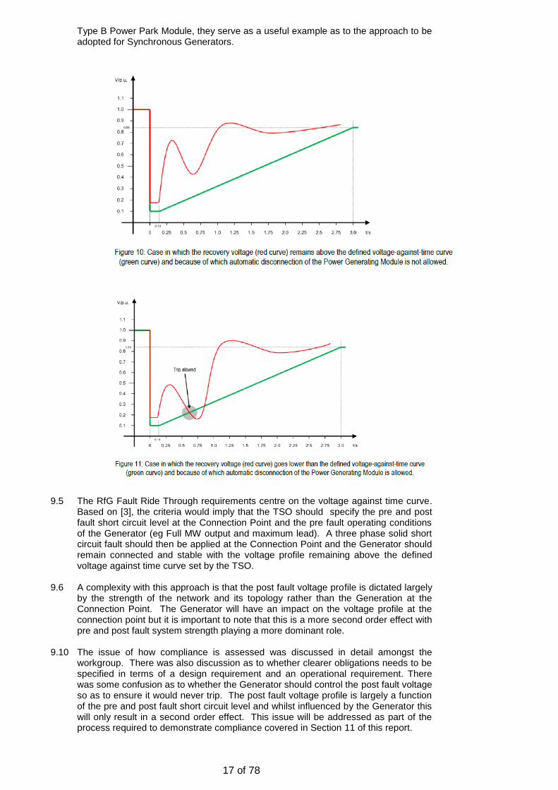
17 of 78
Type B Power Park Module, they serve as a useful example as to the approach to be adopted for Synchronous Generators.
9.5 The RfG Fault Ride Through requirements centre on the voltage against time curve.
Based on [3], the criteria would imply that the TSO should specify the pre and post fault short circuit level at the Connection Point and the pre fault operating conditions of the Generator (eg Full MW output and maximum lead). A three phase solid short circuit fault should then be applied at the Connection Point and the Generator should remain connected and stable with the voltage profile remaining above the defined voltage against time curve set by the TSO.
9.6 A complexity with this approach is that the post fault voltage profile is dictated largely
by the strength of the network and its topology rather than the Generation at the Connection Point. The Generator will have an impact on the voltage profile at the connection point but it is important to note that this is a more second order effect with pre and post fault system strength playing a more dominant role.
9.10 The issue of how compliance is assessed was discussed in detail amongst the
workgroup. There was also discussion as to whether clearer obligations needs to be specified in terms of a design requirement and an operational requirement. There was some confusion as to whether the Generator should control the post fault voltage so as to ensure it would never trip. The post fault voltage profile is largely a function of the pre and post fault short circuit level and whilst influenced by the Generator this will only result in a second order effect. This issue will be addressed as part of the process required to demonstrate compliance covered in Section 11 of this report.

18 of 78
10 Determination of RfG Mode A Parameters as applicable to Synchronous Generating Units directly connected to the Transmission System operating at Supergrid Voltage (Mode A)
10.1 A fundamental requirement of the fault ride through requirements is that on one hand
they should ensure the requirements are sufficiently robust to meet the minimum needs of the Transmission System and on the other be realistic and achievable without placing excessive burden on the Generator.
10.2 As mentioned in section 9 above, the RfG requirements only apply to secured faults,
ie faults cleared in main protection operating times. The RfG requirements are quite specific although there is a requirement for the voltage against time curve (Figure 8.7 above) and parameters (Table 8.9) are to be derived at a National level.
10.3 Taking the extreme ends of these parameter ranges (Table 8.9 above), it is possible
to plot a graph showing the parameter ranges available to TSO’s at a National level. This is shown in Figure 10.3 below.
Figure 10.3 – Range of RfG Voltage Against Time Parameters
10.4 The green curve (RFG Min) refers to the minimum voltage against time curve. Under
this case, the post fault voltage profile would require a reasonably stiff system. The implication being that Generator tripping would be permitted under the least onerous of conditions. On the other hand, the red curve is the most onerous requiring the generating unit to remain connected and stable for quite severe post fault voltage recovery.
10.5 At first glance and reading RfG it would appear that the TSO would be able to select
a voltage against time profile anywhere between the Green and Red line. In practice this is not strictly true as the range of parameters in Table 7.1 of RfG do limit the ability of the TSO to select certain values between these ranges. These restrictions are shown in Figure 10.5 below. This limitation was also reflected back to ENTSO-E but it is not believed this will cause an issue.
Figure 10.5 – Limitations on voltage against time curves

19 of 78
10.6 The workgroup debated the interpretation and implications of the voltage against time curve in some considerable detail. In summary, when a Synchronous Generator is subject to a close up short circuit fault cleared in main protection operating times it should remain connected and stable.
10.7 The workgroup queried as to whether the Generator has to ensure the post fault
voltage profile is maintained above the defined voltage against time curve. The general understanding is that the post fault voltage profile will be dictated largely by the System rather than the performance of the synchronous generator. For the purposes of compliance, a 140ms three phase short circuit fault would be applied at the Connection Point of the Generator. Provided the Generator remains connected and stable and the post fault voltage profile remains above the defined voltage against time curve the Generator would be deemed compliant. In the event that the Generator were to pole slip, then the post fault voltage as seen from the Generator would result in oscillations beyond the defined voltage against time curve under which generator tripping would be permitted. Details of the assessment of Compliance for Mode A faults is covered in section 11 below.
10.8 In covering the rudiments of the RfG requirements, this now brings us to the issues
that need to be taken into account in deriving the voltage against time curve for a directly connected synchronous generator. Under CC.6.3.15.1(a) of the Grid Code, a directly connected generator would be required to remain connected and stable for a solid three phase short circuit fault for up to 140ms in duration. In other words, the Generator should remain connected and stable when the voltage at the connection point is set at zero volts for 140ms. Translating this into the RfG voltage against time curve therefore sets the value of Uret to zero and tclear to 0.14 seconds.
10.9 The subsequent points are more complex to determine as they are potentially more
ambiguous in nature. In general, the post fault voltage profile is more a function of the pre and post fault short circuit level at the connection point rather than the characteristics of the Synchronous Generator itself. However, it is important that an achievable characteristic is set, which on hand is not so onerous that it could result in the generator to pole slip whilst on the other that is so lenient that the generator would be permitted to trip for the most minor of faults.
10.10 In practice, an assessment of stability will be made at the Transmission application
stage. The Transmission System Owner will design the Transmission Network in accordance with the requirements of the Security and Quality of Supply Standards (SQSS). During the application stage, stability studies will be run which will detail the specification of the excitation system (eg onload ceiling voltage and rise time). This specification being an important criteria upon which the stability requirements are assessed.
10.11 So far as the voltage against time curve is concerned, the curve needs to cater for
credible system events but not those which would either be unduly pessimistic or beyond the requirements of the SQSS as these are covered under Mode B faults. It is also vitally important that the Generator does not set its under-voltage protection settings to the same value as the voltage against time curve as this would result in premature tripping. As such, the voltage against time curve needs to consider credible voltage sags and dwells caused by high MVAr demands for example.
10.12 Returning back to the derivation of the voltage against time curve, the value of Uclear
is fixed at 0.25. As this marks the start of the voltage recovery (ie immediately on fault clearance) this point would also take place at 140ms, and therefore is set by tclear.
10.13 The next stage is to consider the remaining parameters of the voltage against time
curve, Urec1, Urec2, trec1, trec2 and trec3. These are more complex due to the potential arbitrary nature of the points that can be selected for the voltage against time curve. Taking into account the effect of post fault voltage oscillations, particularly where there may be high MVAr demands and the analysis undertaken, the voltage against time curve needs to be robust enough to cater for system disturbances cleared in main protection operating times whilst ensuring it is not sufficiently onerous that the requirement is not achievable. An example of the current RTE voltage against time curve is shown in Figure 10.13. In summary this requires the generator to withstand a 100% voltage dip for a period of 150ms, a 50% voltage dip for a further 550ms (total 700ms) and restoration to 1.0p.u volts a further 800ms (total 1500ms) later.

20 of 78
Figure 10.3 – French RTE Low Voltage Ride Through Voltage Against Time Curve 10.14 In deriving a GB voltage against time curve, there is always a concern under high
MVAr demands the post fault voltage could struggle to return to 0.5 p.u at 140ms instantaneously. On this basis and to take this effect into account the value of Urec1 was set at 0.5p.u and trec1 set at 0.25s. Should the voltage still struggle further to recover then a plateau needs to be introduced but it becomes fairly straight forward to determine these values in terms of time and voltage. As a plateau is introduced the value of Urec1 remains at 0.5 p.u and the time trec1 would need to be at or less than the breaker fail operating time of typically 500ms. Based on the fact that the Mode B fault ride through requirements are considered separately from RfG and the study work conducted in Appendix 1 of this report it was deemed a value of 450ms would be appropriate for trec2. The last and final section is to consider the values of Urec2 and trec3. The RfG requirements only cover secured faults which would be cleared within 140ms. As Mode B faults are designed to cover unsecured faults which could result in potentially small voltage deviations (say a voltage dip of 0.15p.u (retained voltage 0.85p.u) for a considerable length of time (eg 3 minutes) and based on the analysis conducted in Appendix 1 of the report, a condition of requiring restoration of the voltage to 1.0p.u seems reasonable. The only remaining criteria is therefore to determine the time trec3. Based on the analysis completed and the approach adopted internationally, a value of 1.5s for trec3 would not be seemed to be unreasonable.
10.15 To summarise, the GB RfG Fault Ride Through Parameters are therefore shown in
Table 10.15 and represented graphically in Figure 10.15.

21 of 78
Voltage Parameters [p.u] Time Parameters [seconds]
Uret: 0 tclear: 0.14
Uclear: 0.25 trec1: 0.25
Urec1: 0.5 trec2: 0.45
Urec2; 1.0 trec3: 1.5
Table 10.15 – Proposed GB Parameters for the Fault Ride Through
Capability of a Synchronous Generating Unit connected at Supergrid Voltage
Figure 10.15 – Proposed GB Voltage against time curve for the Fault Ride Through Capability of a Synchronous Generating Unit connected
at Supergrid Voltage
10.16 The existing GB requirements which RfG leaves to the discretion of the TSO would remain as they are. For completeness these are summarised as follows:-
• Active power should be restored to 90% of the pre- fault active power level within 0.5 seconds of restoration of the voltage. Allowances will be made for oscillations in active power output as currently defined in CC.6.3.5.1(a)(ii).
• During the period of the fault each, Generating Unit shall supply maximum reactive current without exceeding the transient rating of the Generating Unit.
10.17 As mentioned in section 6.5 above it is not the purpose of this report to include corresponding legal text to reflect the above proposals. This element will be picked up by the GC0048 Workgroup.
11 Mode A – Demonstration of RfG Fault Ride Through Compliance at a GB Level
as applicable to any Synchronous Generating Unit directly connected to the Transmission System operating at Supergrid Voltage
11.1 This section of the report details how compliance should be assessed against the
RfG Mode A proposals by statement of the principles to be adopted and then through the use of an example.

22 of 78
11.2 It should also be noted that RfG Articles 51(3), 51(4) (Type B and C Synchronous Power Generating Modules) and RfG Articles 53(3) (Type D Synchronous Power Generating Modules) define the simulation requirements for fault ride through assessment. There is no requirement for actual tests to be completed on Synchronous Power Generating Modules to demonstrate compliance.
11.3 The general process for assessment and subsequent compliance would be expected
to proceed through the following stages. 11.4 At the Generator application stage, National Grid will undertake a stability
assessment to ensure compliance with the SQSS and determine the excitation parameters of the Generator. These studies would generally be undertaken during minimum demand conditions and would also identify if any reinforcement is necessary. The excitation performance requirements would then be reflected in the Bilateral Connection Agreement but it is assumed at this stage that the Generator is fully compliant with the requirements of the Grid Code. Any high level stability issues would generally be identified at this stage. The Bilateral Agreement would also specify the following information to enable the Generator to undertake the necessary compliance work:-
- The Maximum and Minimum Pre Fault Short Circuit Level at the
Connection Point. - The pre fault operating conditions of the Generator (eg Full MW
output, maximum lead) - The Maximum and Minimum Post Fault Short Circuit level at the
Connection Point. 11.5 With details of the Short Circuit levels and Generating Unit parameters available, the
Generator should be in a position to run system studies to asses Mode A Fault Ride Through Compliance.
11.6 During the Workgroup, it was noted that the pre and post fault short circuit level
would be very different as a result of the loss of the line and consequent change in system topology – see Figure 7.1 above. One suggestion was therefore that NGET should provide an equivalent based on the representations shown in Figures 11.6(a) – (c).
Figure 11.6(a) – Pre Fault Test Network Equivalent

23 of 78
Figure 11.6(b) – Test Network Equivalent under Fault Conditions
Figure 11.6(c) – Post Fault Network as an Equivalent 11.7 This approach is adopted by RTE of France as documented in [4]. An example of the
RTE model is shown in Figure 11.7 below.
Figure 11.7 – RTE to Modelling Low Voltage Fault Ride Through
11.8 Following internal research and discussion with the National Grid System Design
department, it was considered that it would be more straight forward to provide a simple model simply quoting the pre and post short circuit level. This simplifies the process and also reduces need to produce an equivalent.

24 of 78
Figure 11.8 – Equivalent Network provided by NGET for Assessment of Fault Ride Through
11.9 Under this arrangement the Generator will need to model the infinite busbar reflecting the pre-fault short circuit level and the post fault short circuit level. As mentioned above both these values will be provided by National Grid.
11.10 The Workgroup discussed i) the type of model that should be used for compliance purposes and ii) the requirement that the post fault voltage returns to 1.0p.u rather than 0.9 p.u. Evidence to demonstrate this is covered in Appendix 1 of the report which showed that stability performance was significantly undermined with a post fault voltage recovery to 0.9p.u rather than 1.0p.u. This effect was demonstrated by studies run by EDF which were independently evaluated by NGET.
11.6 To demonstrate this process, the following example is shown as to how compliance
would be expected to be demonstrated. It needs to be noted that the Generator only needs to apply a fault for 140ms at the point of connection. Under these conditions the Generating Unit should remain connected and stable for a solid three phase balanced or unbalanced fault at the connection point, with active power being restored within 0.5 seconds of fault clearance.
12 Example – Compliance demonstration of a Mode A fault using the RfG
parameters
12.1 This section of the report seeks to give an example of how a Generator would be
expected to undertake Mode A fault ride through compliance if the RfG requirements
had been adopted. A recommendation from this GC0062 Workgroup is that the
GC0048 Workgroup take the information contained in this report for subsequent
coding and ultimate implementation into the GB code.
12.2 For the purposes of this example we are going to assume that a 1500MVA
Synchronous Generator is seeking a connection to the Transmission System at
400kV.
12.3 The Connection Contract has been signed and under the terms of Contract the
Generator is required to satisfy the requirements of the Connection and Use of
System Code (CUSC) which in turns obligates them to satisfy the requirements of the
Grid Code and Bilateral Agreement, the technical requirements being covered in
Appendix F which would specify the excitation ceiling parameters. In this example a
static excitation system has been specified with an on load positive ceiling voltage of
2.0 p.u, a rise time of 50ms and a negative ceiling level of no less than 1.6.p.u and
the installation of a Power System Stabiliser.

25 of 78
12.4 In order for the Generator to assess compliance National Grid will provide the
following data and model as shown in Figure 12.4 below.
Figure 12.4 – Parameters and model issued by NGET for the Generator to
undertake Mode A (RfG Compliant) Fault Ride Through Compliance Studies
12.5 The Generator will then be responsible for inserting their detailed Generating Unit
model into the single machine equivalent. There is no restriction on the type of software modelling tool (eg Power Factory, PSS/E, Eurostag, EMTDC / PSCAD / Matlab) used so long as the Generator can supply traces of Active Power, Voltage, rotor angle and other internal machine parameters on a common time base.
12.6 An example of these traces are shown in Figure 12.6 below – To follow. 12.7 So far as the requirement to restore Active Power within 0.5 seconds of fault
clearance is concerned, the existing GB Grid Code requirement would apply as detailed in CC.6.3.15.1(a)(ii) where the assessment is based on the total active energy during the period immediately after the fault. This requirement is necessary to account for the potential oscillatory nature of the post fault active power generated.
12.8 A question raised on a number of occasions during the Workgroup was what would
happen in the event that compliance could not be demonstrated. For Mode A faults, the initial stability assessment is carried out by NGET at the application stage which is then used to derive the excitation system requirements necessary. In extreme cases it may be necessary for other measures such as system reinforcement. There have and continue to be cases where an offer has been released showing stable results which when tested by the Generator have resulted in unstable results. These issues are generally down to modelling assumptions and under such circumstances NGET will work with the Generator to ensure consistency of models and results.
12.9 For the purposes of compliance, simulation studies will only be necessary. There will
be no requirement to complete real tests or type tests. Under RfG, compliance simulations for Synchronous Power Generating Modules would be required as defined in Article 51 (3), 51 (4) and Article 53(3). In summary these simply refer to demonstration of compliance through simulation studies to demonstrate that the requirements of RfG Article 16 (3) and Article 17(3) can be demonstrated. In practice when the GB Grid Code is updated through the GC0048 Workgroup, additional information will be included in CC.A.4 and CP.A.3.5 which would be along the lines of the simulations highlighted above.

26 of 78
Mode B Fault Ride Through Requirements 13
Section 4 of this report details the background to the fault ride through requirements 13.1with the Mode B requirements being summarised in section 4.5 (e) – (h). In summary the Mode B fault ride through requirements are defined by a voltage duration curve which is defined in Figure 5 of CC.6.3.15.1(b) which is re-produced as Figure 13.1 below.
Figure 13.1 – Current GB Grid Code Mode B Voltage Duration Curve Fault Ride Through Requirements
13.2 Figure CC.6.3.15.1(b) is a voltage duration curve which is not to be confused with a voltage against time curve as defined in RfG. In summary the GB voltage duration curve represents is not a voltage time-time response curve that would be obtained by plotting the transient voltage response at a point on the Transmission System to a disturbance, rather each point on the profile represents the voltage level and associated time duration a Generating Unit must withstand or ride through. A set of examples of the interpretation of Figure 5 are covered in Appendix 4 of the GB Grid Code Connection Conditions (Figures CC.A.4A.3(a), CC.A.4A.3(b) and CC.A.4A.3(c)) [5].
13.3 Since the introduction of these requirements in June 2005, one of the principle issues of concern has been the ability of larger Synchronous Generators to satisfy the Mode B fault ride through requirements, particularly for arduous voltage dips such as a retained voltage of 30% for 384ms or 50% for 710ms. These areas of difficulty are shown in Figure 13.3 below.
Figure 13.3 – GB Grid Code – Mode B Fault Ride Through Requirements – Area of Complexity

27 of 78
13.4 As the RfG document does not cover faults cleared beyond main protection operating times this provides a further degree of freedom in developing a revised Mode B requirement. It was therefore proposed to re-evaluate the GB Mode B voltage duration curve through extensive study work. The remaining part of this section details the high level requirements and conclusions with the accompanying detailed study work covered in Appendix 1, whilst at time same time giving some background as to why the derived voltage duration curve is the shape it is.
13.5 Under worst case conditions Generators would be exposed to a fault on the Transmission System cleared in backup operating times, typically within 500ms. It is accepted that generation local to the fault would be permitted to trip (generally through observed instability), but the purpose of this requirement is to ensure that the Generation remote from the disturbance remains connected and stable. It is acknowledged that generation would be likely to be lost in excess of the infrequent infeed loss (currently 1800MW - as defined under the SQSS) and whilst it is accepted that the low frequency demand disconnection scheme would operate the Transmission System would at least retain some form of robustness against a total blackout.
13.6 An example of such a situation is shown in Figure 13.6(a) and Figure 13.6(b) below which gives an indication of the situation that could arise on the Transmission System in the event of a protection or breaker failure.
Figure 13.6(a)
Figure 13.6(b)

28 of 78
13.7 A multi machine simulation study modelling this exact situation was run on a number of parts on the network including the Drax - Eggborough group which is known to have high concentrations of generation during peak demand conditions. The results of this study are fully detailed in Appendix 1.
13.8 To determine the Mode B requirements there are two important criteria that need to be established. These being:-
• The minimum needs of the Transmission System
• An achievable requirement that Generators can meet.
13.9 In view of this, the following studies and sensitivities were run. These are
summarised below and detailed in Appendix 1.
• The effect on Generators and System voltage remote from a severe
Transmission System fault cleared in backup operating times.
• The effect on Generator stability by varying the and pre and post fault
short circuit ratio.
• Determination of the critical fault clearance time over a range of operating
scenarios and fault levels.
• Variation in results upon Generator MW size. The more sensitive results
were identified with higher MW output plant. Studies were run up to a
maximum Generator size of 1800MW.
13.10 From these studies some important results were derived. These being:-
• Determination of the fault ride through voltage against time curve.
• Determination of pre and post fault voltage requirements
• Determination of pre and post fault short circuit levels
• Methods of determining Mode B compliance via simulation.
13.11 The first stage of this process was to determine the voltage duration curve. Based on
initial study work, three options were initially proposed with a four being presented
based on amendments to option 3. All four options were presented to the workgroup
which are shown in Figure 13.11 below.
Figure 13.11 – Options Considered for Mode B Voltage Duration Curves based on initial
studies.
13.12 Following further internal and external analysis it was confirmed that Option 3 would
be the most appropriate option based on both the minimum needs of the
Transmission System and the ability of Generators to satisfy the above

29 of 78
requirements based on critical fault clearance times against minimum short circuit
levels. Options 1 and 2 were quickly discounted on the basis that system studies
demonstrated that the majority of Generators would be able to survive a voltage
depression from 0.33p.u at 140ms to 0.5p.u at 450ms. However these studies
quickly demonstrated that the pinch point was largely around a retained voltage of
0.5p.u for approximately 450ms. These results are shown in Figure 13.12 which
were run by a Workgroup member and also consistent with the results obtained by
National Grid. A full summary of these results together with sensitivities to fault
level and voltage are covered in Appendix 1 of this report.
Figure 13.12 – Critical Fault Clearing Times for a 1780 MW Generator against proposed
Mode B voltage duration curve.
13.13 The results from these studies (and the corresponding evidence shown in Appendix
1) show that Proposal 1 which is equivalent to Option 3 shown in Figure 13.11
above clearly, demonstrate this to be the optimum requirement. Further analysis
was also conducted where Generators under test where subject to long duration
voltage dips were the retained voltage was in the order of 0.85p.u for a period of
180 seconds (3minutes). Under these scenario’s, generator stability was observed.
Taking these results into account then enables the voltage duration curve to be
finalised as shown in Figure 13.13(a) which removing the 140ms results in Figure
13.13(b) below.

30 of 78
Figure 13.13(a) – Final Proposed Mode B Voltage Duration Curve.
Figure 13.13(b) – Final Proposed Mode B Voltage Duration Curve.
13.14 The implications of these results and proposed requirements also need to be put in
context. It is important to note that under a Mode B fault the Generator is expected to remain connected and stable for a remote fault cleared in backup operating times. This criteria has important assumptions that needs to be undertaken when compliance is undertaken. These can be summarised as follows;
• The Pre and post fault short circuit level would be expected to remain the
same • The pre fault voltage would be assumed to be 1.0p.u. Equally on clearance
of the voltage dip, the post fault voltage would be assumed to recover to 1.0p.u. Analysis showed recovery back to 0.9p.u rather than 1.0p.u to be particularly onerous.
• The fault level was critical in determining these results and on average the post fault Transmission System short circuit level needs to be about 10 times larger than the machine MVA rating for stability to be retained for a Mode B fault.
13.15 Figure 13.15 below shows some examples of a voltage dip that a Generator would be expected ride through. For the purposes of clarity they have been superimposed on the voltage duration curve.

31 of 78
Figure 13.15 – Examples of Voltage dips as seen on the Transmission System
superimposed on the proposed voltage against time curve.
13.16 The workgroup discussed in detail how compliance should be demonstrated in particular the straight line voltage dips as shown in Figure 13.15 above which under fault conditions would be non-linear due to the machine dynamics. To address this concern two methods were proposed.
13.17 The first method for demonstrating Mode B compliance is by application of a fault to
the HV terminals of the Generator Transformer with the Generator set to operate at full output, full MVAr lead. The impedance at the connection point between the transformer and infinite node is adjusted to give the appropriate fault level in Table 2 of Figure 13.17 below. In other words, to demonstrate Mode B compliance, the fault level is determined with reference to the machine size rather than the site specific fault level at the connection point. This process is outlined in Figure 13.17 below.
Figure 13.17 – Method 1 – demonstration of Mode B Fault Ride Through compliance 13.18 Under this method, a fault will result in a voltage decay during the period of the fault
as a result of the machine dynamics. This method will not produce a constant voltage trace as highlighted in Figure 13.15 and therefore it was felt that the fault impedance is selected to give an average volt drop. An example of this is shown in Figure 13.18 below.
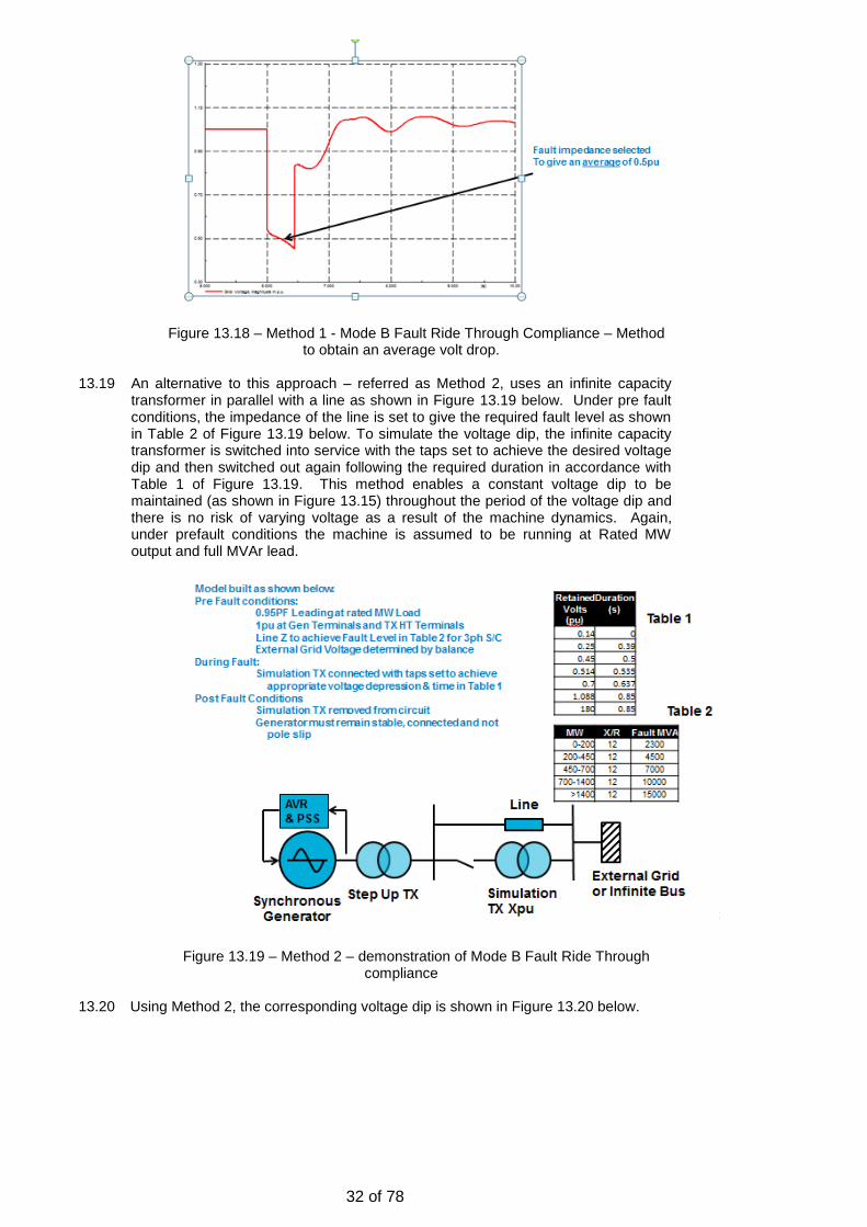
32 of 78
Figure 13.18 – Method 1 - Mode B Fault Ride Through Compliance – Method
to obtain an average volt drop. 13.19 An alternative to this approach – referred as Method 2, uses an infinite capacity
transformer in parallel with a line as shown in Figure 13.19 below. Under pre fault conditions, the impedance of the line is set to give the required fault level as shown in Table 2 of Figure 13.19 below. To simulate the voltage dip, the infinite capacity transformer is switched into service with the taps set to achieve the desired voltage dip and then switched out again following the required duration in accordance with Table 1 of Figure 13.19. This method enables a constant voltage dip to be maintained (as shown in Figure 13.15) throughout the period of the voltage dip and there is no risk of varying voltage as a result of the machine dynamics. Again, under prefault conditions the machine is assumed to be running at Rated MW output and full MVAr lead.
Figure 13.19 – Method 2 – demonstration of Mode B Fault Ride Through
compliance 13.20 Using Method 2, the corresponding voltage dip is shown in Figure 13.20 below.

33 of 78
Figure 13.20 – Method 2 - Mode B Fault Ride Through Compliance – Method to obtain volt drop.
13.21 As highlighted earlier in the report, the Grid Code does not currently mandate
Generators to demonstrate fault ride through compliance for Synchronous Generating Units. It is therefore proposed that CP.A.3.5 and OC5.A.2.1 remain unchanged until implementation of the GC0048 RfG implementation work. However it is intended that the contents of this report will provide a useful guide to the process that could be used to demonstrate compliance.

34 of 78
Specific issues for Transmission Licensees 14
Impact on the National Electricity Transmission System
So far as the Fault Ride Through Mode A requirements are concerned, there will be 14.1no change proposed to the GB Grid Code legal text as a result if this workgroup. The contents of this workgroup report does however provide details of the Workgroups interpretation of the ENTSO-E Requirements for Generators and should be taken forward to the GC0048 RfG implementation workgroup.
With regard to the Mode B requirements, the proposed changes to the legal text are 14.2summarised in Annex 3. In summary these proposals redefine the voltage duration curve and seek to provide a clear interpretation of how the requirements should be interpreted for Synchronous Generating Units. These changes are articulated in Appendix 4 of the Grid Code connection conditions.
It is acknowledged that the package of measures that these proposals introduce 14.3(revised voltage duration curve, restoration of voltage back to 1.0p.u instead of 0.9 p.u and the post fault short circuit levels being a function of machine rating rather than the fault level at the connection point) do result in some relaxations. However it must be recalled that the Mode B fault ride Through requirements are already beyond the requirements of the SQSS and simply act as a last resort to maintain the intetegrity of the Transmission System rather than a complete system shut down. Whilst these proposals may appear to be a relaxation it is fully noted and accepted by National Grid and the workgroup as a whole that the current requirements are largely unachievable. As such, it is believed and recognised that these new proposals provide an optimum balance between the minimum needs of the Transmission System and the capability of a Synchronous Generator.
Specific issues for Transmission Licensees 15
This modification impacts the Owners of Synchronous Generating Units. 15.1
15.2 As noted in section 14.3, this package of measures provides i) a relaxation to the current voltage duration curve and revisions to the post fault behaviour to which Synchronous Generators will be subject. In addition this report provides clear guidance as to how compliance will be demonstrated even though at this stage it is not recommended that the Compliance elements of the Grid Code will be changed.
15.3 So far as the Generators are concerned, this package of measures should provide greater clarity of the obligations required and reduce risk, particularly those which are in the development stage.

35 of 78
Impact on the ENTSO-E Requirements for Generators (RfG) and 16other European Codes
The ENTSO-E Fault Ride Through Requirements only cater for secured faults. As 16.1this report only proposes to change the Grid Code in respect of Mode B faults (ie unsecured faults cleared in backup protection operating times), then there is no conflict with the ENTSO-E RfG document.
16.2 Sections 8 – 12 of this report details the workgroups interpretation of the ENSTO-E
RfG requirements for Mode A faults and how they could be interpreted in GB. These sections of the report have been provided for information and are considered to be invaluable for the GC0048 Workgroup in implementing the RfG Fault Ride Through Requirements.
In addition, the Emergency and Restoration Code (ERC) was also checked in relation 16.2to any fault ride through requirements that may be applicable to unsecured faults. A review of this document did not identify any conflict between the proposals in this report and the ERC. It is therefore not believed that the European Network Codes cause a conflict with these proposals.
Conclusions and Recommendations 17
This report summarises the findings of the GC0062 fault ride through workgroup 17.1following the issues raised in EDF’s paper PP12/04. The issue stems from the fact that a number of Synchronous Generators were struggling to satisfy the fault ride through requirements particularly for faults cleared in backup operating times were the retained voltage was in the region of between 15 – 50% and the corresponding time duration was in the region of between 140ms – 710ms. The suggestion in paper reference PP/12/04 being the introduction of a site specific requirement.
In response, three industry workshops were held in September 2012, November 17.22012 and January 2013. These workshops comprised representatives from both synchronous and asynchronous communities, with the conclusion being at that stage that early adoption of the ENTSO-E Fault Ride Through requirements would provide a solution to the issues raised. The view from the asynchronous (wind farm) community was that whilst the current fault ride through requirements were not ideal, they would not wish to introduce a change and then be exposed to a further requirements if there was a subsequent amendment to the proposed RfG requirements. On this basis, it was proposed that a Fault Ride Through Workgroup was established specifically for Synchronous Generation, the intention being to consider early adoption of the RfG Fault Ride Through Requirements as a vehicle to address the issue. The work was originally proposed to take place in two phases, the first addressing the requirements for directly connected synchronous Generation and the second to address the requirements for Embedded Synchronous Generation.
Following detailed analysis, the Workgroup identified that the RfG requirements only 17.3applied to secured faults (ie faults cleared in main protection operating times) and as such would be unable to address the issues identified in EDF’s issue paper. It was also identified that the parameters available for TSO’s to select as part of the RfG voltage against time curve also had limitations. These issues were not identified as significant but nonetheless were notified to ENTSO-E as an issue.
As RfG is silent on unsecured faults (ie faults cleared in backup operating times) it 17.4was proposed that the Mode B GB Grid Code should be retained with amendments to the voltage – duration curve. Analysis of the ENTSO-E Emergency Restoration Code (ERC) did not identify any additional requirements in relation to faults cleared in backup operating times. Therefore, when the GB Grid Code is updated (post GC0048 implementation) it will need to reflect a new set of Mode A requirements (consistent with the RfG Fault Ride Through requirements) and retain Mode B requirements, which if approved, would be consistent with those proposed in Annex 3 of this report.

36 of 78
In view of these findings, the Workgroup considered whether or not it would be 17.5appropriate to change to the Terms of Reference. However, as much of the analysis had been completed and noting this work would have to be addressed by the RfG Implementation Workgroup (GC0048), it was felt that the report should provide guidance on how the RfG Fault Ride Through Requirements should be interpreted in addition to recommending a GB voltage against time curve. In addition the report provides guidance on how compliance should be demonstrated. These requirements have been covered in sections 8 – 12 of this report and fulfil the requirements in the terms of reference. The report does not however propose legal text for this element of work but it is considered this information will be invaluable for the GC0048 work.
As RfG does not address the issues raised in PP12/04, phase II of the work which 17.6was designed to cover the RfG requirements for Embedded Synchronous Plant will now pass to the GC0048 workgroup. This work should however be simplified in view of the more limited range of values available to the TSO (in respect of the voltage against time curve as defined in Table 3.1 of the RfG) and the approach suggested in this report for directly connected synchronous plant.
As mentioned above and as documented in Appendix 1 of this report, detailed 17.7analysis has been undertaken on the Mode B requirements which has resulted in the development of a revised voltage duration curve. National Grid is also grateful to workgroup members to their input on this work which is believed addresses the minimum needs of the Transmission System whilst at the same time defining a requirement which is achievable for Synchronous Generating Units.
It is therefore suggested, that the proposed Mode B text is in Annex 3 of this report 17.8adopted. It is recognised that this is a relaxation from the current requirements and therefore it seems appropriate that these requirements would apply to all Synchronous Generators not just those who have a Completion Date in the future. This is on the basis that those Generators who can satisfy the current requirements would be capable of meeting the proposed requirements and it also offers a route to those Generators who have had to apply for a derogation against the existing requirements.
As part of the Workgroup discussions, it was also noted that Compliance in the Grid 17.9Code in relation to Synchronous Plant was not well defined. The report has attempted to clarify this issue and the simulations that should be applied. In view of the point raised in section 17.8 above, that the proposed Mode B requirements would apply to all Generators, it is not appropriate that the Compliance section at this stage should be updated as we would not wish existing Generators to undertake addition compliance simulations. However it is envisaged that these requirements for new generators will be clarified when the RfG requirements are updated into the Code following the GC0048 work.
In summary, it is believed the output of the report addresses the original Grid Code 17.10defect in addition to providing further guidance to the GC0048 Workgroup. It is also considered that the proposals are fair and proportionate balancing on one hand the minimum needs of the Transmission System and on the other the capability of Synchronous Generators.
Recommendations
17.11 The GCRP is recommended to endorse the conclusions of this report and
associated legal text (Annex 3) and approve its progression to industry consultation.

37 of 78
Assessment 18
Impact on Greenhouse Gas emissions
The proposal facilitates the connection for all sizes of Synchronous Generating Units 18.1to the National Electricity Transmission System (NETS). This will increase competition allowing a greater variation in primary energy sources thereby reducing greenhouse gas emissions.
Assessment against Grid Code Objectives
The change proposed better facilitates the Grid Code objectives: 18.2
(i) to permit the development, maintenance and operation of an efficient, coordinated and economical system for the transmission of electricity;
(ii) to facilitate competition in the generation and supply of electricity (and without limiting the foregoing, to facilitate the national electricity transmission system being made available to persons authorised to supply or generate electricity on terms which neither prevent nor restrict competition in the supply or generation of electricity);
(iii) subject to sub-paragraphs (i) and (ii), to promote the security and efficiency of the electricity generation, transmission and distribution systems in the national electricity transmission system operator area taken as a whole; and
(iv) to efficiently discharge the obligations imposed upon the licensee by this license and to comply with the Electricity Regulation and any relevant legally binding decisions of the European Commission and/or the Agency.
This modification allows relaxation to the Mode B Fault Ride Through requirements 18.3which are currently believed to be excessively onerous to the point they are unachievable This proposal provides Generators with much easier access to the Transmission System and facilitates competition.
This report also provides clarity on how Mode B fault ride through compliance should 18.4be demonstrated.
The change proposed does not impact the implementation of relevant provisions of 18.5the European Commission’s Connection Codes at this time.
Impact on core industry documents
The GB Grid Code 18.6
Impact on other industry documents
None 18.7
Impact on Bilateral Agreements
None 18.8
Implementation
The Workgroup proposes that, should the proposals be taken forward, the proposed 18.9changes be implemented 10 business days after an Authority decision.
38 of 78
References
[1] – H/04 Consultation available at :-
http://www2.nationalgrid.com/WorkArea/DownloadAsset.aspx?id=13419
[2] – Requirements for Generators available at:-
https://www.entsoe.eu/Documents/Network%20codes%20documents/NC%20RfG/draft_ec_
networkCodesJune.pdf
[3] – Network Code for Requirements for Grid Connection Applicable to all Generators frequently asked questions - 19 June 2012 – available at:- https://www.entsoe.eu/fileadmin/user_upload/_library/consultations/Network_Code_RfG/120626_-_NC_RfG_-_Frequently_Asked_Questions.pdf [4] – RTE Documentation technique de reference, Article 4.3 – Stabilité, Installation raccordée au réseau d’interconnexion: http://clients.rte france.com/htm/fr/mediatheque/telecharge/reftech/01-09-14_complet.pdf available at:-https://clients.rte-france.com/htm/fr/mediatheque/telecharge/reftech/01-09-14_complet.pdf [5] – GB Grid Code Issue 5, Revision 14 – available at:- http://www2.nationalgrid.com/UK/Industry-information/Electricity-codes/Grid-code/The-Grid-code/

39 of 78
Annex 1 – Grid Code Issue 19

40 of 78
Annex 2 – Terms of Reference 20
Fault Ride Through Workgroup
TERMS OF REFERENCE
Background
In January 2012, EDF Energy submitted Paper reference PP12/04 to the Grid Code 20.1Review Panel on the issues relating to the ability of synchronous Generators to meet the current Grid Code Fault Ride Through requirements. In summary the paper proposed that where a Generator was unable to satisfy the voltage duration profile defined in Figure 5 of CC.6.3.15, the Grid Code be amended to propose where the generic profile could not be met, the User may request a location specific profile which may be used for compliance purposes.
National Grid welcomed the suggested paper and whilst acknowledging that some 20.2synchronous generating plant struggles to demonstrate compliance against CC.6.3.15 of the Grid Code, was concerned that by adopting an agreed voltage duration profile on a connection site specific bilateral basis, it would not be fully transparent to all Generators. To address the issue raised by EDF Energy, National Grid held a set of industry stakeholder Workshops in September / November 2012 and January 2013 to discuss the issues and propose a way forward...
Full details of the presentations and notes of the Workshops including the 20.3background, issues, options and possible solutions are available on National Grid’s website from the following link:-
http://www.nationalgrid.com/uk/Electricity/Codes/gridcode/workinggr
oups/Fault+Ride+Through/
In summary the key conclusions drawn from the Workshops were:- 20.4
i) Adopting a site specific voltage duration profile as initially suggested
in paper PP12/04 would not be fully transparent and risks potential discrimination between Generators. It was however recognised that Synchronous Generators demonstrating compliance against CC.6.3.15 of the Grid Code has in the past, and continues to be problematical.
Of all the options considered workshop participants concluded that further 20.5consideration should be given to early adoption of the ENTSO-E Network Code Requirements for Generators (RfG) Fault Ride Through Requirements, specifically targeted at Large Synchronous Generators. This is on the basis that a) The GB Industry Codes will need to be aligned to the ENTSO-E Codes by 2016 / 2017 as required under European law, b) Under the current provisions of the ENTSO-E RfG, Synchronous Generators are required to meet different fault ride through requirements as compared to Power Park Modules c) The voltage duration curve for synchronous plant under the ENTSO-E RfG Fault Ride Through Requirements is considered less onerous than the current GB Grid Code resulting in a more straight forward compliance process and d) the National parameters selected for fault ride through would be subject to the full GB Governance arrangements and therefore transparent.
Workshop participants acknowledged that whilst there were still issues associated 20.6with Asynchronous Generation, the fault ride through issues as presented in PP12/04 were largely associated with Synchronous Plant and wind farm developers and manufacturers were not keen to undergo a full set of additional research and type

41 of 78
tests when they were broadly happy with the current GB Grid Code fault ride through requirements.
ii) A formal Grid Code Fault Ride Through Working Group should be
established to examine the implications of early adoption of the ENTSO-E Requirements for Generators in respect of Synchronous Generation, including the specification of GB Parameters.
iii) The scope of the work will initially consider the fault ride through
issues associated with Large Directly Connected Synchronous Generators (as defined in the Grid Code), and then consider the application to Embedded Generation. For the purposes of this working group, only Synchronous Generation within the current GB Framework definitions1 shall be considered (ie Large and Medium Power Stations). For the avoidance of doubt, the ENTSO-E RfG Fault Ride Through requirements are simply being used as a solution to the issues raised in Paper PP12/04 and are not part of an a ENTSO-E RfG / GB implementation programme.
A summary of these workshops, and the intention to establish a formal Grid Code 20.7Working Group was presented to the January 2013 GCRP.
In addition to the discussions held during the Fault Ride Through Workshops, there 20.8have also been two additional ENTSO-E RfG developments which are considered to fit well with this work. These are summarised as follows:-
(a) As part of ongoing work to consider options for applying the EU
network codes to the GB regulatory framework, National Grid together with DNO representatives and Ofgem have been considering options for integrating the ENTSO-E RfG and GB Grid Code. As part of this process, Fault Ride Through has been selected as an example of how the ENTSO-E RfG and GB Codes can be integrated. The results of this work will be presented to JESG Members for their consideration and feedback
(b) As a separate element of work, ENTSO-E is also aiming to develop
a pilot to explore specific examples of how the National Choices within RfG will be established under the different regulatory arrangements of EU Member States. Since the terms of Reference of this Fault Ride Through Working Group were initially prepared, National Grid has subsequently learnt that the pilot scheme as initially proposed has been delayed due to limited interest amongst EU TSO’s members. As a TSO member, National Grid is fully supportive of this work and sees Fault Ride Through as an excellent example to submit as part of this pilot exercise should it be held in the future, not least because of the synergy with this GCRP Working Group.
In summary, the ENTSO-E RfG is expected to enter the Comitology phase later this year with approval in 2014. There will then be a 2 - 3 year implementation period in which the National Codes will be updated to ensure consistency with the European Code. As one recommendation of the Fault Ride Through Workshops was to consider early adoption of the
1 The GB Grid Code requirements are classified on the basis of Large (100MW and above in England and Wales,
30MW and above in SPT’s Area and 10MW and above in SHETL’s Area). Medium Power Stations exist only in
England and Wales of between 50 – 100MW. In Europe the ENTSO-E RfG classifies Generation into Type A
(400W – 1MW and connected below 110kV), Type B (1MW – 10MW and connected below 110kV), Type C (10MW
– 30MW and connected below 110kV) and Type D (above 30MW and connected above 110kV).

42 of 78
ENTSO-E RfG for Synchronous Plant these additional European developments fit well with this stream of work.
Governance
The Workgroup shall formally report to the GCRP in March 2014. For the avoidance 20.9of doubt, this Workgroup and any proposed changes to the Grid Code will be under the full auspices of the Grid Code Review Panel Governance process. In other words, the ENTSO-E RfG Fault Ride Through requirements are seen as a potential solution for addressing the issues raised in paper reference PP12/04 and not part of the wider ENTSO-E / GB Grid Code implementation or regulatory process.
Membership
The Workgroup shall comprise a suitable and appropriate cross-section of 20.10experience and expertise from across the industry, which shall include:
Name Role Representing
Graham Stein Chair National Grid
Paul Wakeley Technical Secretary (1) National Grid
Richard Woodward Technical Secretary (2) National Grid
Antony Johnson National Grid Representative National Grid
Richard Ierna National Grid Representative National Grid
Julian Wayne Authority Representative Ofgem
Herve Meljac Industry Representative EDF
David Draper Industry Representative Horizon
Philip Belben Industry Representative Horizon
Karim Kariou Industry Representative GDF Suez –
Representing NuGen
Campbell McDonald Industry Representative SSE Generation
Philip Jenner Industry Representative Formerly RWE
Maxime Buquet Industry Representative General Electric
As the initial work will concentrate on Large Directly connected Synchronous 20.11Generators, and then subsequently consider Embedded Synchronous Generation, it is recommended that in order to minimise delays, the work group initially comprises of members whose interests are associated with directly connected plant and then once this element of work is completed, the membership is expanded to include stakeholders with an interest in Large and Medium Embedded Synchronous Plant.
Meeting Administration
The frequency of Workgroup meetings shall be defined as necessary by the 20.12Workgroup chair to meet the scope and objectives of the work being undertaken at that time.
National Grid will provide technical secretary resource to the Workgroup and handle 20.13administrative arrangements such as venue, agenda and minutes.
The Workgroup will have a dedicated section on the National Grid website to enable 20.14information such as minutes, papers and presentations to be available to a wider audience.
Scope
The Workgroup shall consider and report on the following: 20.15
(a) Using information currently available, understand the interpretation of the ENTSO-E RfG Fault Ride Through requirements and its ability to address the issues raised in Grid Code paper PP12/04.

43 of 78
(b) Develop GB specific requirements and parameters initially for directly connected Synchronous Generation to then be immediately followed by Embedded Synchronous Generation. It is the intention of this working group that it will provide clarity to Generators and ensure consistency with the ENTSO-E RfG Code. The output of this work will feed into the ENTSO-E RfG pilot programme (should it proceed) which is specifically aimed at implementing the ENTSO-E RfG and National Code in addition to the selection of National parameters.
(c) The scope of the work will only cover the GB Grid Code and be applicable to
Directly Connected and Embedded Large and Medium Power Stations. Any changes (if proposed) would only use existing terms within the GB Grid Code eg Large, Medium and Small Power Stations rather than Type A, Type B, Type C and Type D Power Generating Modules. There is no intention to introduce RfG terms into this drafting unless there is a specific reason to do so.
(d) The Workgroup will inform GCRP and JESG Members of the progress of the work and the developments (if such work proceeds) of the ENTSO-E pilot programme.
VOLTAGE

44 of 78
Annex 3 - Proposed Legal Text
(b) Supergrid Voltage dips on the Onshore Transmission System greater
than 140ms in duration.
(1b) Requirements applicable to Onshore Synchronous Generating Units
subject to Supergrid Voltage dips on the Onshore Transmission System
greater than 140ms in duration
In addition to the requirements of CC.6.3.15.1 (a) each Onshore
Synchronous Generating Unit shall:
(i) remain transiently stable and connected to the System without
tripping of any Onshore Synchronous Generating Unit for
balanced Supergrid Voltage dips and associated durations on
the Onshore Transmission System anywhere on or above the
heavy black line shown in Figure 5a. Appendix 4A and Figures
CC.A.4A1.3 (a), (b) and (c) provide an explanation and
illustrations of Figure 5a; and,
Figure 5a
(ii) provide Active Power output at the Grid Entry Point, during
Supergrid Voltage dips on the Onshore Transmission System
as described in Figure 5a, at least in proportion to the retained
balanced voltage at the Onshore Grid Entry Point (for Onshore
Generating Units and Onshore Power Park Modules) or
Interface Point (for Offshore Generating Units, OTSDUW Plant
and Apparatus and Offshore Power Park Modules) (or the
retained balanced voltage at the User System Entry Point if
Embedded) except in the case of a Non-Synchronous
Generating Unit or OTSDUW Plant and Apparatus or Power
Park Module where there has been a reduction in the
Intermittent Power Source or in the case of OTSDUW Active
Power transfer capability in the time range in Figure 5 that
restricts the Active Power output or in the case of an OTSDUW
Active Power transfer capability below this level and shall
generate maximum reactive current (where the voltage at the
Grid Entry Point, or in the case of an OTSDUW Plant and
Apparatus, the Interface Point voltage, is outside the limits
specified in CC.6.1.4) without exceeding the transient rating limits
of the Onshore Synchronous Generating Unit OTSDUW Plant

45 of 78
and Apparatus or Power Park Module and any constituent
Power Park Unitand,
(iii) restore Active Power output (or, in the case of OTSDUW, Active
Power transfer capability) following Supergrid Voltage dips on
the Onshore Transmission System as described in Figure 5a,
within 1 second of restoration of the voltage to 1.0p.u of the
nominal voltage at the:
Onshore Grid Entry Point for directly connected Onshore
Synchronous Generating Units and Onshore Power Park
Modules or,
Interface Point for Offshore Generating Units, OTSDUW
Plant and Apparatus and Offshore Power Park Modules
or,
User System Entry Point for Embedded Onshore
Synchronous Generating Units and Embedded Onshore
Power Park Modules or,
User System Entry Point for Embedded Medium Power
Stations and Embedded DC Converter Stations not
subject to a Bilateral Agreement which comprise and
utilising Onshore Synchronous Generating Units and with
an Onshore User System Entry Point (irrespective of
whether they are located Onshore or Offshore)
to the minimum levels specified in CC.6.1.4 to at least 90% of the
level available immediately before the occurrence of the dip,
except in the case of a Non-Synchronous Generating Unit,
OTSDUW Plant and Apparatus or Power Park Module where
there has been a reduction in the Intermittent Power Source in
the time range in Figure 5 that restricts the Active Power output
or, in the case of OTSDUW, Active Power transfer capability
below this level. Once the Active Power output or, in the case of
OTSDUW, Active Power transfer capability has been restored to
the required level, Active Power oscillations shall be acceptable
provided that:
- the total Active Energy delivered during the period of the
oscillations is at least that which would have been delivered if
the Active Power was constant
- the oscillations are adequately damped.
For the avoidance of doubt a balanced Onshore Transmission
System Supergrid Voltage meets the requirements of CC.6.1.5 (b)
and CC.6.1.6.
(2b) Requirements applicable to OTSDUW Plant and Apparatus and Power
Park Modules subject to Supergrid Voltage dips on the Onshore
Transmission System greater than 140ms in duration
In addition to the requirements of CC.6.3.15.1 (a) each Generating
Unit OTSDUW Plant and Apparatus, or each Power Park Module
and / or any constituent Power Park Unit, each with a Completion
Date on or after the 1 April 2005 shall:
(i) remain transiently stable and connected to the System without
tripping of any Generating Unit OTSDUW Plant and Apparatus,
or Power Park Module and / or any constituent Power Park Unit,
for balanced Supergrid Voltage dips and associated durations on
the Onshore Transmission System (which could be at the

46 of 78
Interface Point) anywhere on or above the heavy black line
shown in Figure 5b. Appendix 4A and Figures CC.A.4A2.3 (a), (b)
and (c) provide an explanation and illustrations of Figure 5b; and,
Supergrid Voltage Duration
Supergrid Voltage Level (% of Nominal)
90
15
80 85
0.14s 2.5s 1.2s 3 minutes
Figure 5b
(ii) provide Active Power output at the Grid Entry Point or in the
case of an OTSDUW, Active Power transfer capability at the
Transmission Interface Point, during Supergrid Voltage dips
on the Onshore Transmission System as described in Figure
5b, at least in proportion to the retained balanced voltage at the
Onshore Grid Entry Point (for Onshore Generating Units and
Onshore Power Park Modules) or Interface Point (for Offshore
Generating Units, OTSDUW Plant and Apparatus and
Offshore Power Park Modules) (or the retained balanced
voltage at the User System Entry Point if Embedded) except in
the case of a Non-Synchronous Generating Unit or OTSDUW
Plant and Apparatus or Power Park Module where there has
been a reduction in the Intermittent Power Source or in the case
of OTSDUW Active Power transfer capability in the time range in
Figure 5b that restricts the Active Power output or in the case of
an OTSDUW Active Power transfer capability below this level
and shall generate maximum reactive current (where the voltage
at the Grid Entry Point, or in the case of an OTSDUW Plant and
Apparatus, the Interface Point voltage, is outside the limits
specified in CC.6.1.4) without exceeding the transient rating limits
of the Generating Unit OTSDUW Plant and Apparatus or
Power Park Module and any constituent Power Park Unit; and,
(iii) restore Active Power output (or, in the case of OTSDUW, Active
Power transfer capability), following Supergrid Voltage dips on
the Onshore Transmission System as described in Figure 5b,
within 1 second of restoration of the voltage at the:
Onshore Grid Entry Point for directly connected Onshore
Generating Units and Onshore Power Park Modules or,
Interface Point for Offshore Generating Units, OTSDUW
Plant and Apparatus and Offshore Power Park Modules
or,
User System Entry Point for Embedded Onshore
Generating Units and Embedded Onshore Power Park
Modules or,

47 of 78
User System Entry Point for Embedded Medium Power
Stations which comprise of Power Park Modules and
Embedded DC Converter Stations not subject to a
Bilateral Agreement and with an Onshore User System
Entry Point (irrespective of whether they are located
Onshore or Offshore)
to the minimum levels specified in CC.6.1.4 to at least 90% of the
level available immediately before the occurrence of the dip
except in the case of a Non-Synchronous Generating Unit,
OTSDUW Plant and Apparatus or Power Park Module where
there has been a reduction in the Intermittent Power Source in
the time range in Figure 5b that restricts the Active Power output
or, in the case of OTSDUW, Active Power transfer capability
below this level. Once the Active Power output or, in the case of
OTSDUW, Active Power transfer capability has been restored to
the required level, Active Power oscillations shall be acceptable
provided that:
- the total Active Energy delivered during the period of the
oscillations is at least that which would have been delivered if
the Active Power was constant
- the oscillations are adequately damped.
For the avoidance of doubt a balanced Onshore Transmission
System Supergrid Voltage meets the requirements of CC.6.1.5 (b)
and CC.6.1.6.

48 of 78
APPENDIX 4 - FAULT RIDE THROUGH REQUIREMENTS
APPENDIX 4A - FAULT RIDE THROUGH REQUIREMENTS FOR
ONSHORE SYNCHRONOUS GENERATING UNITS, ONSHORE POWER
PARK MODULES, ONSHORE DC CONVERTERS, OTSDUW PLANT AND
APPARATUS AT THE INTERFACE POINT, OFFSHORE POWER PARK
MODULES IN A LARGE POWER STATION AND OFFSHORE DC
CONVERTERS IN A LARGE POWER STATION WHICH SELECT TO
MEET THE FAULT RIDE THROUGH REQUIREMENTS AT THE
INTERFACE POINT
CC.A.4A.1 Scope
The fault ride through requirement is defined in CC.6.3.15.1 (a), (b) and
CC.6.3.15.3. This Appendix provides illustrations by way of examples only
of CC.6.3.15.1 (a) (i) and further background and illustrations to
CC.6.3.15.1 (1b) (i) and CC.6.3.15.1 (2b) (i) and is not intended to show all
possible permutations.
CC.A.4A.2 Short Circuit Faults At Supergrid Voltage On The Onshore Transmission
System Up To 140ms In Duration
For short circuit faults at Supergrid Voltage on the Onshore
Transmission System (which could be at an Interface Point) up to 140ms
in duration, the fault ride through requirement is defined in CC.6.3.15.1 (a)
(i). Figures CC.A.4A.1 (a) and (b) illustrate two typical examples of voltage
recovery for short-circuit faults cleared within 140ms by two circuit breakers
(a) and three circuit breakers (b) respectively.
Figure CC.A.4A.1 (a)

49 of 78
Figure CC.A.4A.1 (b)
CC.A.4A.3 Supergrid Voltage Dips On The Onshore Transmission System Greater
Than 140ms In Duration
CC.A.4A1.3 Requirements applicable to Onshore Synchronous Generating Units
subject to Supergrid Voltage dips on the Onshore Transmission System
greater than 140ms in duration
For balanced Supergrid Voltage dips on the Onshore Transmission
System having durations greater than 140ms and up to 3 minutes the fault
ride through requirement is defined in CC.6.3.15.1 (1b) and Figure 5a
which is reproduced in this Appendix as Figure CC.A.4A1.2 and termed the
voltage–duration profile.
This profile is not a voltage-time response curve that would be obtained by
plotting the transient voltage response at a point on the Onshore
Transmission System (or User System if located Onshore) to a
disturbance. Rather, each point on the profile (i.e. the heavy black line)
represents a voltage level and an associated time duration which connected
Onshore Synchronous Generating Units must withstand or ride through.
Figures CC.A.4A1.3 (a), (b) and (c) illustrate the meaning of the voltage-
duration profile for voltage dips having durations greater than 140ms.

50 of 78
Figure CC.A.4A1.2
Figure CC.A.4A1.3 (a)
Figure CC.A.4A1.3 (b)
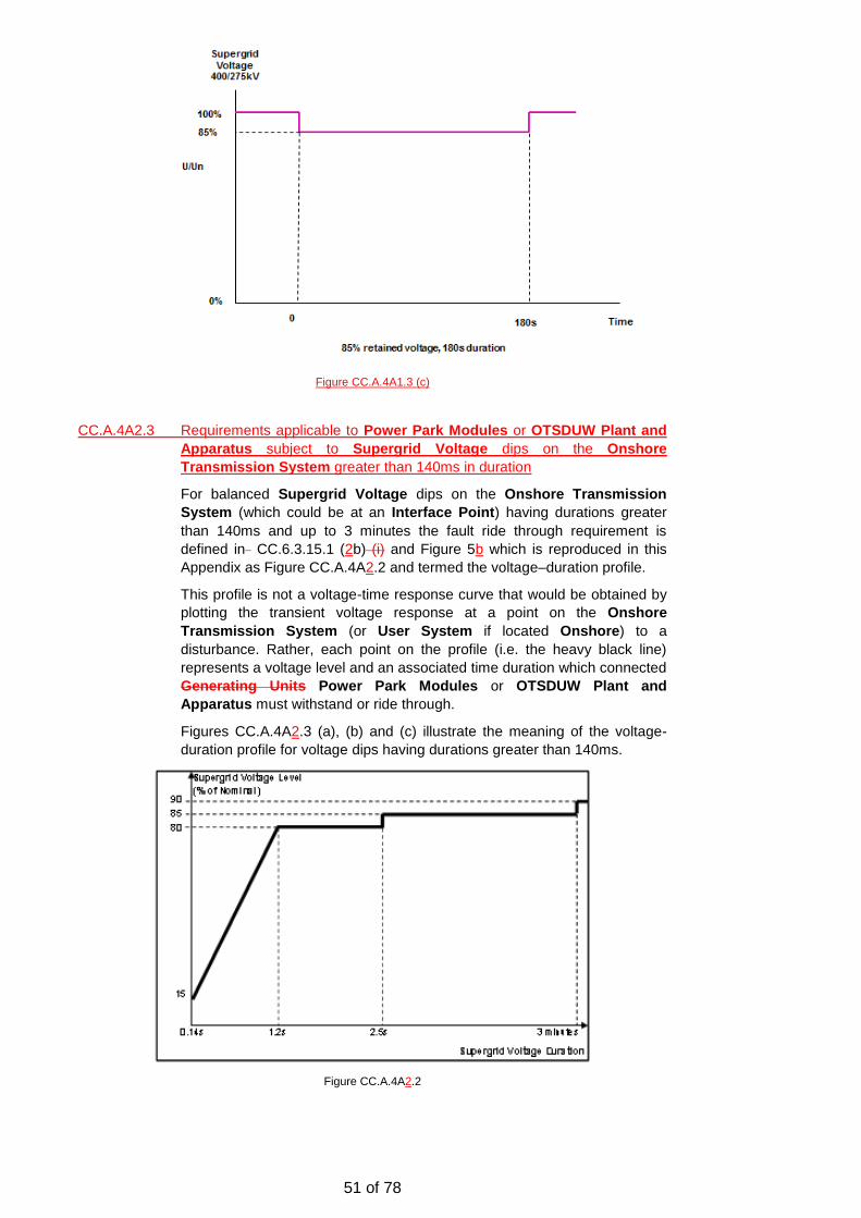
51 of 78
Figure CC.A.4A1.3 (c)
CC.A.4A2.3 Requirements applicable to Power Park Modules or OTSDUW Plant and
Apparatus subject to Supergrid Voltage dips on the Onshore
Transmission System greater than 140ms in duration
For balanced Supergrid Voltage dips on the Onshore Transmission
System (which could be at an Interface Point) having durations greater
than 140ms and up to 3 minutes the fault ride through requirement is
defined in CC.6.3.15.1 (2b) (i) and Figure 5b which is reproduced in this
Appendix as Figure CC.A.4A2.2 and termed the voltage–duration profile.
This profile is not a voltage-time response curve that would be obtained by
plotting the transient voltage response at a point on the Onshore
Transmission System (or User System if located Onshore) to a
disturbance. Rather, each point on the profile (i.e. the heavy black line)
represents a voltage level and an associated time duration which connected
Generating Units Power Park Modules or OTSDUW Plant and
Apparatus must withstand or ride through.
Figures CC.A.4A2.3 (a), (b) and (c) illustrate the meaning of the voltage-
duration profile for voltage dips having durations greater than 140ms.
Figure CC.A.4A2.2
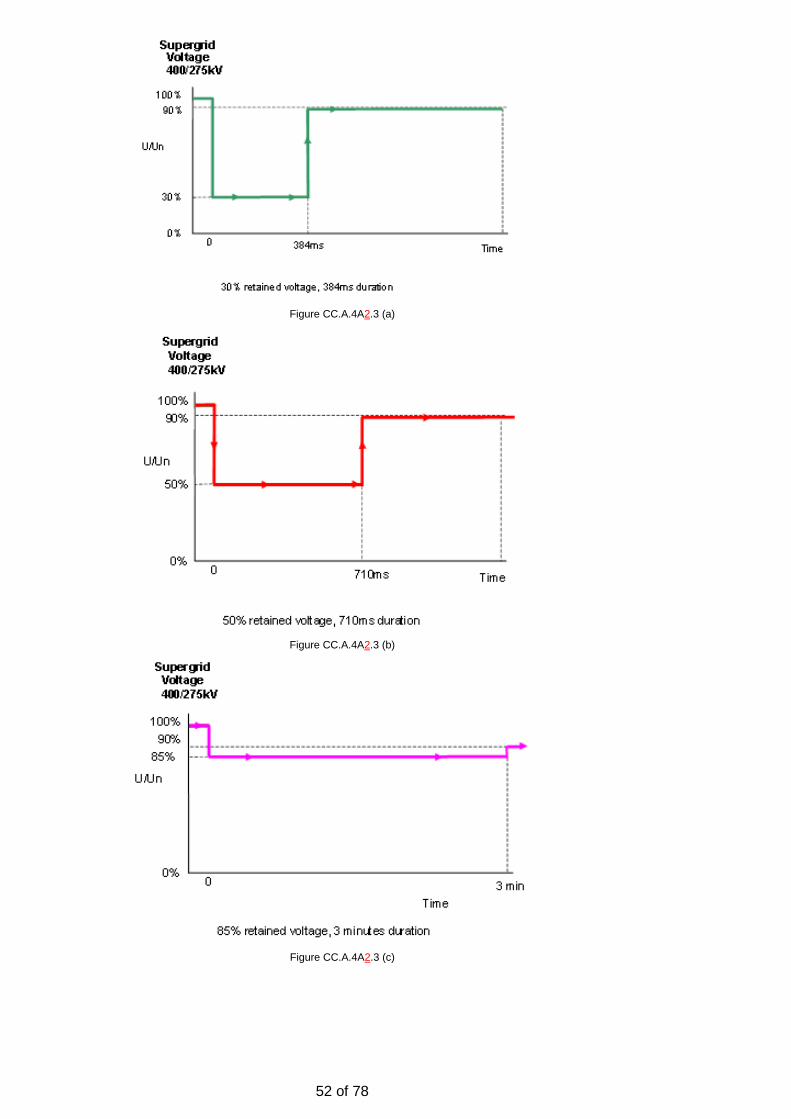
52 of 78
Figure CC.A.4A2.3 (a)
Figure CC.A.4A2.3 (b)
Figure CC.A.4A2.3 (c)

53 of 78
Appendix 1 - Study Evidence
A.1 This section includes the results of various studies performed by National Grid and Generators to demonstrate the effects of mainly Mode B faults where short circuits are cleared in backup protection times.
A.2 Mode A faults were also considered but were not generally as onerous as the Mode B faults. Generators performed some very interesting critical clearing time studies which demonstrate 0pu and 0.5pu retained volts are the two areas where the tolerance between the requirements and the physics of the machines are at their smallest.
A.3 The study work is generally presented in the chronological order that it was produced and presented to the work group. The accompanying text describes the objectives of the studies and what is demonstrated by them.
A.4 Initially the studies considered the effects of various trips in back up protection times at Eggborough and Seabank. These included summer and winter cases with low and high renewable content based on contracted positions similar to the current network.
A.5 It was expected that summer minimum with high wind penetration would be the worst case as this would represent the weakest system. However at current network penetration of renewable technology, the results were similar and the effects observed on the synchronous generation under consideration were not significant.
A.6 Studies were also carried out to determine the conditions developers, generators and manufactures could reasonably be expected to encounter and would be required to prove compliance against. The method of compliance, single machine against an infinite bus was also validated against the equivalent study performed on the full GB system.
Effects of Trip at Seabank
A.7 The initial studies carried out at Seabank considered the effects of a double circuit trip on the OHL from Imperial Park to Melksham and Clifynydd to Whitson and Seabank for low wind winter peak conditions, as shown in the diagram below. As stated earlier, studies were performed at summer minimum and winter peak with different generation profiles but these didn’t have significant effects on the results.

54 of 78
Figure A.7 – Location of faults for Seabank 700ms 50% Fault
A.8 The fault applied to the line depressed the volts at Seabank to 50% for 700ms. Most of the breakers tripped within 140ms but one breaker was assumed to fail and remained closed requiring the backup protection to operate after 700ms and clear the fault by isolating the bus bar connected to the other side of the failed breaker.
Figure A.8 – Voltage depression at Seabank 400kV and various other locations.
A.9 Various voltages were monitored around the system to see how the voltage depression affects the rest of the system.
A.10 As a result of breaker X105 failing to open and the backup protection opening (X410, X305 and X130), three generators SEAB_8A, SEAB_8B and SEAB_8C are lost at Seabank. However this is around 700MW and is under the SQSS infrequent infeed loss and no load disconnection is required.
Figure A.10 – Breakers opened by back up protection.
A.11 The results show the remaining machine SEAB_8C survives this onerous fault condition and doesn’t pole slip, as do all other machines on the system. The rotor angle deviation is contained to within about +60degrees.

55 of 78
Figure A.11 – Rotor angle deviation at Seabank and various other locations.
A.12 Most back up protection is expected to operate in less than 500ms. The study however, considered a more onerous case of 700ms to ensure a margin existed between the requirement and the worst case backup protection time. (Note: The model used was: “FRT Base Case - Post GC WG Aug 2014” and study case “001 Working Group Jul 2014 (As Actions)\ Mon Winter DP2014-15-FRT-SEAB-700ms50%”).
Effects of Trip at Eggborough
A.13 The Eggborough generator was tested at 0.5pu for 550ms, 600ms and 700ms with all disturbances initially starting with a voltage dip to 0.pu for 140ms. The fault was applied to both Eggborough to Drax circuits with circuit breaker X505 failing at Eggborough resulting in the longer fault conditions.
Figure A.13 – Eggborough substation and running arrangement showing breakers which
operate to clear stuck breaker X505.
A.14 Only the 550ms simulation survived without pole slipping. Unlike Seabank, Eggborough has a slow rotating exciter, no PSS and relatively low gain AVR although with voltage depressions of this size, it is still likely to produce timely field forcing. However the above, particularly the exciter, probably accounts for much of the performance.

56 of 78
A.15 Note: Under winter peak conditions, additional generation (EGGB_81) was
connected at Eggborough and lost as part of the stuck breaker as the bus bar it was connected to tripped. In addition to the initial double circuit lost as part of the fault on the DRAX-EGGB lines, a further additional line (EGGB-STSB/NEEP) was lost as part of the bus bar trip although this is a three ended circuit and the other two nodes do remain connected.
Worst case breaker stuck at Seabank and Drax
A.16 Following the initial studies carried out at Eggborough and Seabank it was noted that with the standard default running arrangement, more severe conditions could be achieved by simply selecting different fault locations and stuck breakers.
A.17 Under these conditions it is possible to produce failures which result in large losses of generation, which cannot be contained by frequency response and reserve which ultimately leads to load disconnection. However as Mode B is only intended to prevent a total system collapse and is not covered by the SQSS requirements, this is therefore considered acceptable.
A.18 Under these more severe conditions Seabank and surrounding machines performed well and survived without significant loss of generation and therefore maintained all loads. However because of the quantity of generators in the Drax region, in particular located at Eggborough and Ferry Bridge a different picture emerged.
A.19 The worst case that was created incurred a loss of approximately 3.5GW of generation which would probably result in about 1.7 to 2.2GW of load disconnection. However the contagion was contained and the machines beyond Ferry Bridge did not pole slip.
A.20 The following two sub sections describe the worst case studies for Seabank and Drax/Eggborough respectively.
Winter Peak Study at Seabank with fault on MELK-SEAB and IMPP-MELK
A.21 It was noted that a fault on the double circuit from Melksham to Seabank and Imperial Park would be more onerous with the standard running arrangements, as this would leave the three CCGT machines to export about 750MW down a single circuit. Furthermore these machines have fast response static exciters together with a PSS installed. Consequently if they cannot achieve the requirement it might be considered unreasonable.
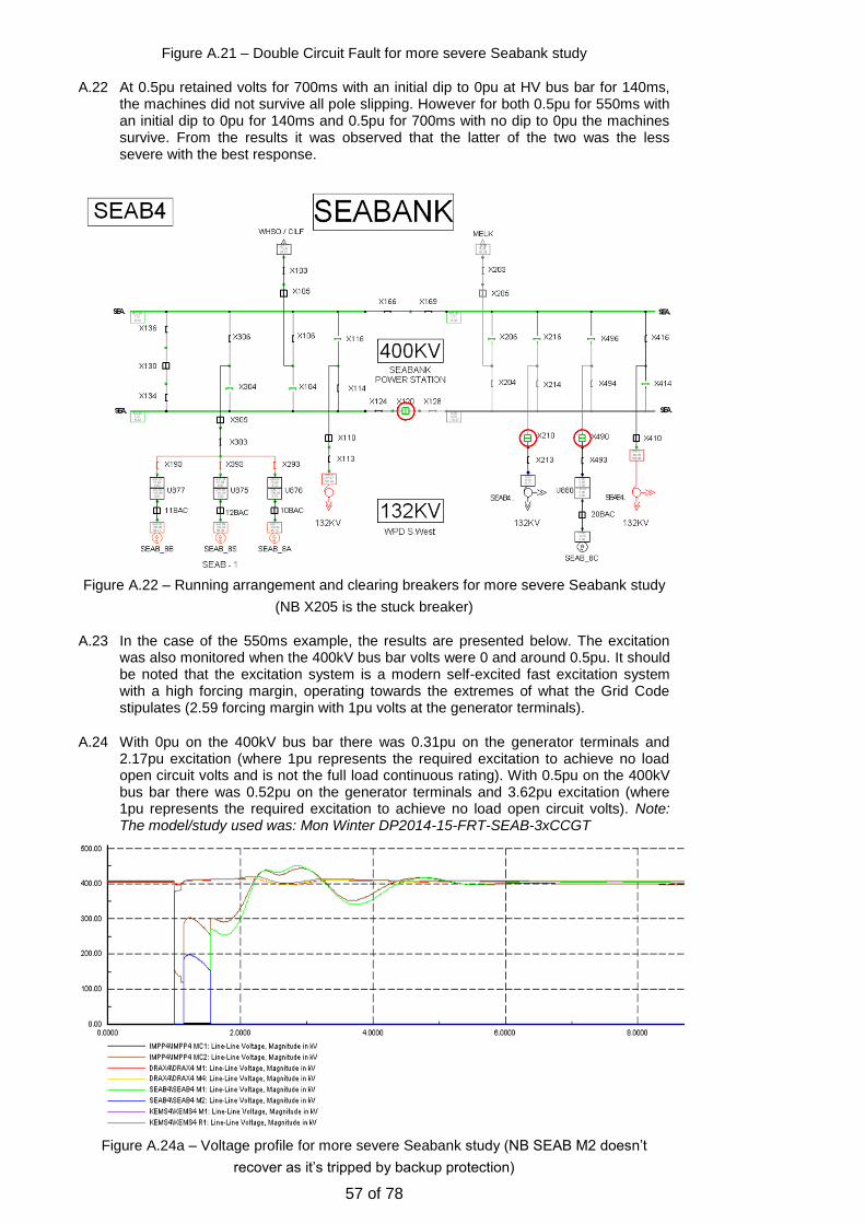
57 of 78
Figure A.21 – Double Circuit Fault for more severe Seabank study
A.22 At 0.5pu retained volts for 700ms with an initial dip to 0pu at HV bus bar for 140ms, the machines did not survive all pole slipping. However for both 0.5pu for 550ms with an initial dip to 0pu for 140ms and 0.5pu for 700ms with no dip to 0pu the machines survive. From the results it was observed that the latter of the two was the less severe with the best response.
Figure A.22 – Running arrangement and clearing breakers for more severe Seabank study
(NB X205 is the stuck breaker)
A.23 In the case of the 550ms example, the results are presented below. The excitation was also monitored when the 400kV bus bar volts were 0 and around 0.5pu. It should be noted that the excitation system is a modern self-excited fast excitation system with a high forcing margin, operating towards the extremes of what the Grid Code stipulates (2.59 forcing margin with 1pu volts at the generator terminals).
A.24 With 0pu on the 400kV bus bar there was 0.31pu on the generator terminals and 2.17pu excitation (where 1pu represents the required excitation to achieve no load open circuit volts and is not the full load continuous rating). With 0.5pu on the 400kV bus bar there was 0.52pu on the generator terminals and 3.62pu excitation (where 1pu represents the required excitation to achieve no load open circuit volts). Note: The model/study used was: Mon Winter DP2014-15-FRT-SEAB-3xCCGT
Figure A.24a – Voltage profile for more severe Seabank study (NB SEAB M2 doesn’t
recover as it’s tripped by backup protection)

58 of 78
Figure 24b – Voltage profile as seen at generator terminals of various machines for more
severe Seabank study
Figure A.24c – Active Current (i.e. Power at 1pu volts) as seen at generator terminals of
various machines for more severe Seabank study

59 of 78
Figure A.24d – Reactive Current (i.e. Reactive Power at 1pu volts) as seen at generator
terminals of various machines for more severe Seabank study
Figure A.24e – Rotor Angle deviation as seen at various machines for more severe
Seabank study
Winter Peak Study with fault on DRAX–THOM/KEAD 1 and 2 with a fault
Impedance of 0 Ohms for 550ms
A.25 This study considered what would happen if there was a fault on the DRAX-THOM/KEAD circuits near Drax with no fault impedance and a stuck breaker at Drax. At DRAX, G2 is lost as a result of the stuck breaker, G1 and G3 pole slip and are lost as do EGGB G1 and G3 which are also lost along with Ferry Bridge G3 and G4 which also pole slip.
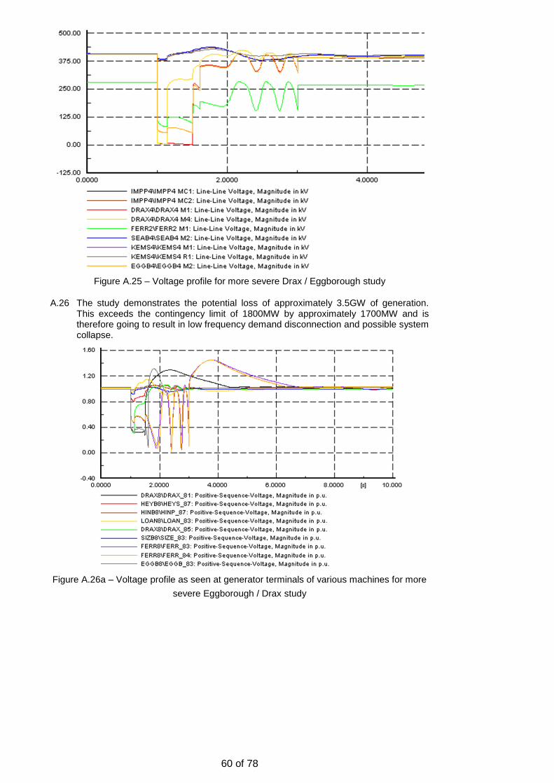
60 of 78
Figure A.25 – Voltage profile for more severe Drax / Eggborough study
A.26 The study demonstrates the potential loss of approximately 3.5GW of generation. This exceeds the contingency limit of 1800MW by approximately 1700MW and is therefore going to result in low frequency demand disconnection and possible system collapse.
Figure A.26a – Voltage profile as seen at generator terminals of various machines for more
severe Eggborough / Drax study

61 of 78
Figure A.26b – Active Current (i.e. Power at 1pu volts) as seen at generator terminals of
various machines for more severe Eggborough / Drax study
A.27 The voltage depression at Drax M1 is approximately 0pu and at Drax M4 is 0pu for 140ms and 0.73pu for the remaining 550ms. After the initial 140ms the retained voltage at Eggborough is between 0.14-0.19pu and at Ferry Bridge is between 0.35-0.45pu which are both below 0.5pu for 500ms. The study clearly demonstrates contagion from one substation to the next. In practice a real fault may not be as severe as the fault may be unbalanced or high impedance.
Note: The model/study used was: Mon Winter DP2014-15-FRT-DRAX-550msSC
Figure A.27a – Reactive Active Current (i.e. Reactive Power at 1pu volts) as seen at
generator terminals of various machines for more severe Eggborough / Drax study

62 of 78
Figure A.27b – Change in Rotor Angle as seen at generator terminals of various machines
for more severe Eggborough / Drax study
Winter Peak Study with fault on DRAX–THOM/KEAD 1 with a fault Impedance
of 0 Ohms for 550ms
A.28 This study considered what would happen if there was a fault on the DRAX-THOM/KEAD circuit near Drax with no fault impedance and a stuck breaker at Drax. It differs from the previous study as only one circuit has a fault (in the previous study both circuits had experienced a fault). A similar result is obtained but this time the Ferry Bridge machines do not pole slip.
Figure A.28 – Voltage profile for more severe single circuit Drax / Eggborough study
A.29 The study demonstrates the potential loss of approximately 2.5GW of generation. This exceeds the contingency limit of 1800MW by approximately 700MW and is therefore going to result in low frequency disconnection.
A.30 At DRAX G2 is lost as a result of the stuck breaker, G1 and G3 pole slip and are lost as do EGGB G1 and G3 which are also lost.
A.31 The voltage depression at Drax M1 is approximately 0pu and at Drax M4 is 0pu for 140ms and 0.77-0.79pu for the remaining 550ms. After the initial 140ms the retained voltage at Eggborough are between 0.15-0.2pu and at Ferry Bridge 0.4-0.48pu. The study clearly demonstrates contagion from one station to the next and that for Ferry Bridge 0.5pu at 550ms is close to its limit.

63 of 78
Figure A.31a – Voltage profile as seen at generator terminals of various machines for more
severe single circuit Eggborough / Drax study
Figure A.31b – Active Current (i.e. Power at 1pu volts) as seen at generator terminals of
various machines for more severe single circuit Eggborough / Drax study

64 of 78
Figure A.31c – Reactive Active Current (i.e. Reactive Power at 1pu volts) as seen at
generator terminals of various machines for more severe single circuit Eggborough / Drax
study
Figure A.31d – Change in Rotor Angle as seen at generator terminals of various machines
for more severe single circuit Eggborough / Drax study
Note: The model/study used was: Mon Winter DP2014-15-FRT-DRAX-550msSC-1L
Comparison of Single Machine and Multi Machine Studies
A.32 For generators to test their machines are compliant they need to produce a single machine model and subject it to the applicable study conditions and must be confident that these models accurately represent what would happen in if all machines were modelled.
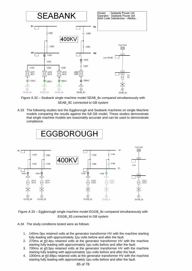
65 of 78
Figure A.32 – Seabank single machine model SEAB_8x compared simultaneously with
SEAB_8C connected to GB system
A.33 The following studies test the Eggborough and Seabank machines on single Machine models comparing the results against the full GB model. These studies demonstrate that single machine models are reasonably accurate and can be used to demonstrate compliance.
Figure A.33 – Eggborough single machine model EGGB_8x compared simultaneously with
EGGB_83 connected to GB system
A.34 The study conditions tested were as follows:
1. 140ms 0pu retained volts at the generator transformer HV with the machine starting
fully leading with approximately 1pu volts before and after the fault. 2. 270ms at <0.4pu retained volts at the generator transformer HV with the machine
starting fully leading with approximately 1pu volts before and after the fault. 3. 700ms at <0.5pu retained volts at the generator transformer HV with the machine
starting fully leading with approximately 1pu volts before and after the fault. 4. 1000ms at <0.68pu retained volts at the generator transformer HV with the machine
starting fully leading with approximately 1pu volts before and after the fault.
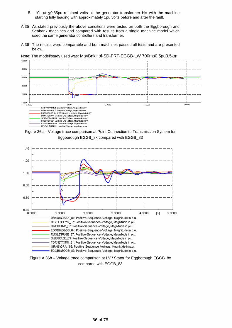
66 of 78
5. 10s at <0.85pu retained volts at the generator transformer HV with the machine starting fully leading with approximately 1pu volts before and after the fault.
A.35 As stated previously the above conditions were tested on both the Eggborough and Seabank machines and compared with results from a single machine model which used the same generator controllers and transformer.
A.36 The results were comparable and both machines passed all tests and are presented below.
Note: The model/study used was: MayBnkHol-SD-FRT-EGGB-LW 700ms0.5pu0.5km
Figure 36a – Voltage trace comparison at Point Connection to Transmission System for
Eggborough EGGB_8x compared with EGGB_83
Figure A.36b – Voltage trace comparison at LV / Stator for Eggborough EGGB_8x
compared with EGGB_83
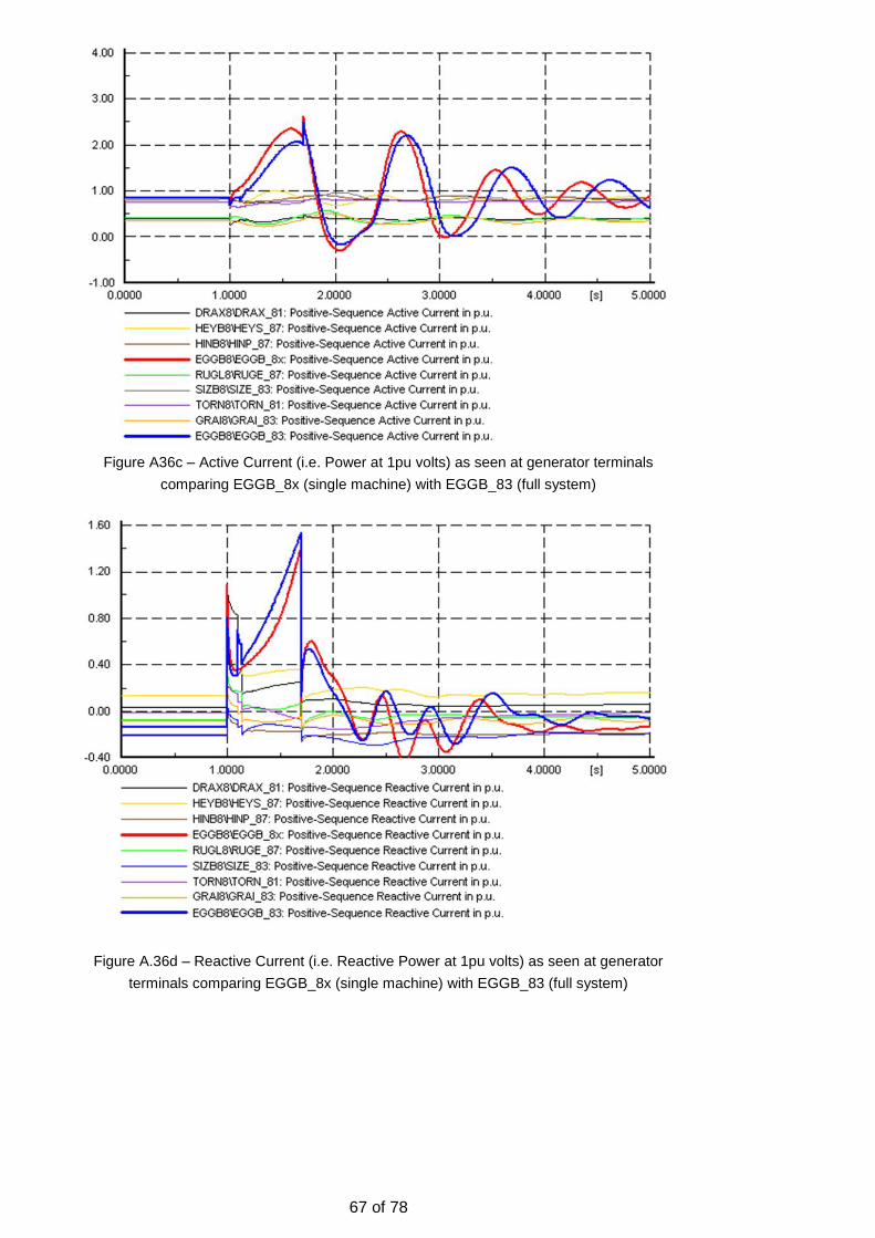
67 of 78
Figure A36c – Active Current (i.e. Power at 1pu volts) as seen at generator terminals
comparing EGGB_8x (single machine) with EGGB_83 (full system)
Figure A.36d – Reactive Current (i.e. Reactive Power at 1pu volts) as seen at generator
terminals comparing EGGB_8x (single machine) with EGGB_83 (full system)

68 of 78
Figure A36e – Deviation in Rotor Angle as seen at generator terminals comparing
EGGB_8x (single machine) with EGGB_83 (full system)
Considerations for Static Exciters
A.37 Static Exciters and Rotary Exciters are the two main types of excitation system in general use on Synchronous Generators connected to the GB Transmission System.
A.38 For Rotary Excitation Systems, the field of the synchronous machine is supplied by a second generator mounted on the same shaft known as the exciter. The field winding of the exciter is in turn controlled by the voltage regulator to produce constant terminal voltage at the stator of the main machine. The supply for the voltage regulator is typically supplied by a third generator also mounted on the shaft which has permanent magnets and known as a Permanent Magnet Generator (PMG) or Pilot Exciter. It doesn’t require any control system, its output voltage is typically variable and dependant on the machine speed and he load on it.
A.39 In a static excitation system the field of the synchronous machine is directly supplied by the voltage regulator electronics through an excitation transformer which is supplied from the terminals of the Generator. This is necessary as the supply can be many hundreds or thousands of amps.
A.40 Static exciters are much quicker at responding because they only have to overcome the inductance of the main field winding whereas the rotary excitation system encounters the delay of a second machine. However the rotary exciter has a secure supply, which is not affected by the fault. In contrast, for a static exciter, a close up fault to the synchronous machine terminals suppresses the voltage and therefore the supply to the excitation system which can affect its performance.
A.41 For secured Mode A faults, the static exciters ability to respond quickly is typically more advantageous as the fault duration is short. However for Mode B faults where the fault duration is longer, the loss of supply may significantly affect performance.
A.42 A series of studies were performed on the Eggborough (Rotary) and Seabank (Static) excitation systems where a single bus model was compared to the full system results but the line length in the single machine model was gradually increased. The intention was to study the effects of introducing additional line impedance.
A.43 The additional line impedance has little effect on the rotary excitation system but a significant effect on the static exciter, which largely appeared to be due to the post fault voltage recovery which also was believed to affect the voltage regulator performance.

69 of 78
A.44 The two studies below demonstrate the effect on the rotary excitation system from Eggborough where the line was extended from 0.5km to 20km and 30km respectively. Whilst the waveforms change, with the original 0.5km results (see Figures A36a-e) there is no major impact on the response. (Note: The model/study used was: MayBnkHol-SD-FRT-EGGB-LW 700ms0.5pu20km).
Figure A.44a Eggborough single M/C study (same as figure 0a-e but with 20km of OHL).
Top to Bottom and Left to Right, Volts on HV of TX, Stator Volts, Active Current, Reactive
Current & Rotor Angle.

70 of 78
Note: The model/study used was: MayBnkHol-SD-FRT-EGGB-LW 700ms0.5pu30km
Figure A.44b Eggborough single M/C study (same as figure A.36a-e but with 30km of OHL).
Top to Bottom and Left to Right, Volts on HV of TX, Stator Volts, Active Current, Reactive
Current & Rotor Angle.
A.45 The three studies below demonstrate the effect on the static excitation system from Seabank where the line was extended from 0.5km to 20km and 30km respectively. Unlike the rotary exciter system there is a considerable effect on the static excitation system response post fault.

71 of 78
Note: The model/study used was: MayBnkHol-SD-FRT-SEAB-LW500ms0.4pu 0.5km
Figure A.45a Seabank single M/C study with 0.5km of OHL. Top to Bottom and Left to
Right, Volts on HV of TX, Stator Volts, Active Current, Reactive Current & Rotor Angle.

72 of 78
Note: The model/study used was: MayBnkHol-SD-FRT-SEAB-LW500ms0.4pu20km
Figure A.45b Seabank single M/C study with 20km of OHL. Top to Bottom and Left to Right,
Volts on HV of TX, Stator Volts, Active Current, Reactive Current & Rotor Angle.

73 of 78
Note: The model/study used was: MayBnkHol-SD-FRT-SEAB-LW500ms0.4pu30km
Figure A.45c Sea Bank single M/C study with 30km of OHL. Top to Bottom and Left to
Right, Volts on HV of TX, Stator Volts, Active Current, Reactive Current & Rotor Angle.
Test cases for a range of machines including 1800MW
A.46 In addition to the various studies presented, many additional studies were also performed including studies on the new generation of larger machines whose ratings exceed 1600MVA. These machines typically encounter lower fault levels relative to their MVA rating simply because the machine rating is so high.
A.47 In addition, machines above 1600MVA are permitted a lower short circuit ratio of 0.4 as opposed to the 0.5 required by machines below this rating. This rule is implemented for practical reasons, as it reduces the iron required in the stator reducing cost weight and the associated transportation problems. However the lower short circuit ratio also reduces the stability limit of the machine making it more susceptible to pole slipping.
A.48 Two different machine and excitation system designs were therefore tested using machine ratings of 2082MVA and 1466MVA. The first used a conventional rotating

74 of 78
exciter the other a static exciter. Both machines were tested with initial conditions of 1pu volts, a 15000MVA fault level return to 1pu volts post fault.
A.49 The machines were tested with the following voltage dips and durations:
1. 0.00pu 140ms 2. 0.93pu 250ms 3. 0.50pu 450ms 4. 0.64pu 700ms 5. 0.80pu 2500ms 6. 0.85pu until steady state
NB for the last test, the voltage reference was changed once the system had settled to simulate the over excitation limit operating.
A.50 The voltage dips were induced using two different methods. The first method applied a short circuit of appropriate impedance to bring the voltage down to the correct level. The second applied a zero (or near zero) impedance voltage source at the HV terminal of the generator transformer. Both methods were applied at all voltage dips and durations.
A.51 Both machines passed all the tests and it was found that the results were pretty much the same and that no advantage was gained by using either of the two methods to set the voltage depression. However the low impedance voltage source does ensure the voltage depression is constant throughout the test. In contrast the voltage depression changes for the short circuit method.
A.52 It should be noted that because the voltage changes when using the short circuit method it is important that the short circuit impedance is chosen such that average voltage achieved is equivalent to the level used for the voltage source.
Machine capability vs System Requirements
A.53 The following study results were produced by a Generator currently building Power Stations utilising larger Synchronous Machine (i.e. 1500MW or larger). As previously stated, Machines of this size are typically worst case in terms of Fault Ride Through requirements, mainly due to the lower short circuit ratio (typically 0.4 as opposed to 0.5) and lower system strength (i.e. system Fault Level relative to M/C MVA rating).
Figure A.53 – Typical Capability for M/C >1500MW
A.54 The studies were conducted looking from the perspective of machine capability. They were performed using a single machine model similar to the type utilised in the National Grid studies. They show the critical clearance times of the machine model verses various requirements discussed during the work group meetings.

75 of 78
A.55 The graphs show the most onerous requirements occur at 0.5pu for a Mode B fault and the 0pu case which is related to the Mode A fault, as these areas are were the requirement and capability lines are most likely to initially cross.
Figure A.55 – Sensitivity to Grid Strength
A.56 Figure A.55 shows how the same Synchronous Machines capability varies with Grid
strength. NB the 0.21, 0.15 and 0.05pu refers to the fault infeed from the system
where 1pu is 10GVA at 400kV.
Figure A.56 – Sensitivity to Final Voltage
A.57 Figure A.56 shows how the same Synchronous Machines capability varies with final voltage. In the two examples given the generator HV terminal starts at 1pu then reduces to a voltage and for a time dictated by the proposals (the line represents a series of rectangular capability pulses) after which it either returns to 1pu or 0.9pu.

76 of 78
Figure A.57 – Sensitivity to Final Voltage and Grid Strength
A.58 Figure A.57 shows how the same Synchronous Machines capability varies with both final voltage and grid strength.
Leading Power Factor under High Voltage Conditions
A.59 In order to estimate the likelihood of particular machines operating with a leading power factor, the GB Transmission System model was dispatched for a summer minimum condition with 99 generators connected and running.
M/C 1-20 MW O/P
MVAr O/P
Rated MW
Rated MVAr
% MVAr Dispatch Notes
Maximum 661.1 -191.0 685.0 251.7 93.3% % on 0.95PF
Average 328.4 -123.8 479.5 174.3 72.6% - " -
Median 352.6 -124.0 397.1 145.9 66.9% - " -
Minimum -278. 1
-64.0 292.0 97.4 58.1% Pump Storage in Pump Mode
M/C 21-40 MW O/P
MVAr O/P
Rated MW
Rated MVAr
% MVAr Dispatch Notes
Maximum 660.0 -112.0 672.0 246.8 53.0% % on 0.95PF
Average 303.5 -57.7 474.9 173.7 32.6% - " -
Median 270.8 -47.4 500.0 183.6 34.7% - " -
Minimum 120.4 -15.1 138.1 50.7 14.9% - " -
M/C 41-60 MW O/P
MVAr O/P
Rated MW
Rated MVAr
% MVAr Dispatch Notes
Maximum 612.9 -30.3 685.0 251.7 14.9% % on 0.95PF
Average 125.2 -5.0 163.1 59.6 3.5% - " -
Median 16.0 0.0 20.4 6.9 0.0% - " -
Minimum -72.8 0.0 3.3 1.2 0.0% - " -
M/C 61-80 MW O/P
MVAr O/P
Rated MW
Rated MVAr
% MVAr Dispatch Notes
Maximum 58.3 0.0 58.1 21.4 0.0% % on 0.95PF
Average 14.3 0.0 18.4 6.5 0.0% - " -
Median 11.5 0.0 15.3 5.3 0.0% - " -
Minimum 1.9 0.0 6.7 2.3 0.0% - " -
M/C 81-99 MW O/P
MVAr O/P
Rated MW
Rated MVAr
% MVAr Dispatch Notes
Maximum 656.0 0.0 672.0 416.4 0.0% % on 0.85PF
Average 146.6 14.9 215.8 133.2 -5.1% - " -

77 of 78
Median 20.1 0.0 20.7 12.1 0.0% - " -
Minimum 8.0 105.7 7.5 4.6 -25.4% - " -
A.60 The dispatched MVAr operating point of the machines was then listed with the most leading listed first. The table below summarises the results breaking them down into five groups of approximately 20 Machines (M/C’s).
A.61 From the results, for the top 20 machines the dispatch range was 58.1% to 93.3% with an average of 72.6%. These machines varied in size from 292MW to 685MW. (NOTE: Whilst many figures are quoted for each group of 20 machines the numbers in each row are not necessarily related to the same machine. Positive values of the %MVAr dispatch, this is calculated against a rated value of 0.95PF leading, whereas the negative values represent lagging power factors and are calculated against a rated value of 0.85PF).
A.62 The table indicates that there is a significant possibility of machines being dispatched for leading Power Factor operation and that it is therefore reasonable to test the worst case where the machine is operating in the lead.
Fault level vs Machine Size
A.63 Studies were performed at various generation sites to establish the ratio of machine MVA to the Fault Level at the respective site. The model was configured for a typical summer minimum dispatch.
A.64 From these results we can see the fault infeed varies from 1105MVA to 29272MVA with an average of 13484MVA. The machine size is proportional to the MVA fault level which varies from 0.35% to 8.42% with an average of 3.52%.
A.65 The worst case fault level is therefore 1/0.0842 or 11.88 times greater than the MVA rating of the machine.
A.66 The table below shows typical values for about a third of the machines dispatched.
A.67 Whilst these results typically demonstrate a ratio of >10 for Machine Rating to fault infeed measured in MVA, we must bear in mind:
A. There are conceivable scenarios which may result in lower ratios.
B. More than one machine may connect at a specific site and under these conditions the MVA of the machines may need to be aggregated effectively lowering the ratio and stability margin.

78 of 78
M/C Name Power Station MW
(0.85MVA) M/C
MVA
Fault Infeed
MVA
Relative Size
MC% Relative
Size
CORY_81 Cory 79.05 93.00 1105.11 8.42% 11.9
HUER_81 Hunterston B 659.60 776.00 9394.56 8.26% 12.1
ABTH_89 Aberthaw B 499.80 588.00 7686.24 7.65% 13.1
ABTH_89 Aberthaw B 499.80 588.00 8034.61 7.32% 13.7
FIDF_83 Fiddlers Ferry 499.80 588.00 8430.68 6.97% 14.3
TORN_81 Torness B 685.10 806.00 12020.52 6.71% 14.9
HATL_81 Hartlepool 659.60 776.00 13288.06 5.84% 17.1
HINP_87 Hinkley Point B 659.60 776.00 14167.41 5.48% 18.3
SAES_8A Saltend South 401.20 472.00 8630.65 5.47% 18.3
SIZE_84 Sizewell B 660.45 777.00 15032.22 5.17% 19.3
ESSO_81 ESSO Fawley 138.13 162.50 3179.77 5.11% 19.6
HEYS_87 Heysham 2 671.93 790.50 17980.14 4.40% 22.7
SEAB_8C Seabank 393.13 462.50 12287.00 3.76% 26.6
DRAX_86 Drax 659.60 776.00 23323.06 3.33% 30.1
GRAI_83 Grain 660.03 776.50 24470.05 3.17% 31.5
RUGE_86 Rugeley B 499.80 588.00 18907.26 3.11% 32.2
COTT_83 Cottam 499.80 588.00 19352.77 3.04% 32.9
EGGB_82 Eggborough 499.80 588.00 21379.27 2.75% 36.4
RATS_81 Ratcliffe-On-Soar 499.80 588.00 21861.68 2.69% 37.2
DRAX_82 Drax 659.60 776.00 29272.70 2.65% 37.7
BPGR_81 BP Grangemouth 144.50 170.00 6517.63 2.61% 38.3
DINO_82 Dinorwig 280.50 330.00 13931.29 2.37% 42.2
EGGB_83 Eggborough 499.80 588.00 25472.40 2.31% 43.3
WBUR_81 West Burton 499.80 588.00 25648.76 2.29% 43.6
RATS_81 Ratcliffe-On-Soar 499.80 588.00 27564.99 2.13% 46.9
CONQ_8A Connahs Quay 363.04 427.10 22813.72 1.87% 53.4
WYLF_81 Wylfa 316.20 372.00 20255.38 1.84% 54.4
CLUN_81 Clunie 11kV 19.55 23.00 1569.08 1.47% 68.2
CEAN_81 Ceannocroc 11kV 16.15 19.00 1334.68 1.42% 70.2
DAMC_8A Damhead Creek 274.55 323.00 25712.65 1.26% 79.6
DEAN_82 Deanie 11kV 17.85 21.00 2942.31 0.71% 140.1
PITL_81 Pitlochry Hydro 7.50 8.82 1624.52 0.54% 184.2
KIOR_81 Kilmorack 11kV 9.35 11.00 2688.28 0.41% 244.4
KIOR_81 Kilmorack 11kV 9.35 11.00 2971.38 0.37% 270.1
CASS-1 Cassley Hydro PS 3.34 3.93 1120.16 0.35% 285.4
Max 685.10 806.00 29272.70 8.42% 285.4
Min 3.34 3.93 1105.11 0.35% 11.9
Average 384.20 452.00 13484.88 3.52% 60.7
Median 499.80 588.00 13288.06 2.75% 36.4
Figure A.68 – Reactive Dispatch of Machines for Low Load
A.68 Any studies performed by Generators in order to prove compliance with the Grid
Code, Fault Ride Through, Mode B requirements are likely to be performed on a
single machine infinite bus model or equivalent. Based on the evidence of the table
presented and for the reasons described above, it was decided a machine to
system fault in feed ratio of 10:1 (fault level to machine size) or slightly greater was
sensible.