shuaibu et al: techniques for ensuring fault ride …
TRANSCRIPT
SHUAIBU et al: TECHNIQUES FOR ENSURING FAULT RIDE-THROUGH CAPABILITY OF DFIG WTS 39
*Corresponding author: [email protected] doi: http://dx.doi.org/10.4314/njtd.v18i1.6
ABSTRACT: Renewable energy sources (RES) are being integrated to electrical grid to complement the conventional
sources to meet up with global electrical energy demand. Among other RES, Wind Energy Conversion Systems
(WECS) with Doubly Fed Induction Generator (DFIG) have gained global electricity market competitiveness because
of the flexible regulation of active and reactive power, higher power quality, variable speed operation, four quadrant
converter operation and better dynamic performance. Grid connected DFIG-based WECS are prone to disturbances in
the network because of direct connection of stator windings to grid. The ability of the Wind Turbine (WT) to remain
connected during grid faults is termed the Fault Ride-Through (FRT) capability. The grid code requirement for
integrating the DFIG-based WTs to power networks specified that they must remain connected and support the grid
stability during grid disturbances of up to 1500 ms. The use of compensation devices offers the best FRT compliance
thereby protecting the DFIG and the converters from voltage fluctuations and over currents during the grid fault. The
paper presents a review of techniques employed in ensuring FRT compliance. The article also proposes the state-of-
the-art techniques for compensating voltage sag/swell and limiting the fault short-circuit current.
KEYWORDS: Renewable energy sources, DFIG, wind turbine system, fault ride-through, grid codes, dual-functional DVR
[Received Jul. 10, 2020; Revised Dec. 28, 2020; Accepted Feb. 13, 2021] Print ISSN: 0189-9546 | Online ISSN: 2437-2110
I. INTRODUCTION
Concerns about global warming and depleting fossil fuels
gave rise to the intense venture to Renewable Energy Sources
(RES) like solar, wind, geothermal, tidal energy sources etc.
As at January 2018, about 25% of world power generation
came from renewable energy sources (Pioro et al., 2019). Of
the RES highlighted above, wind energy became more
prominent with 450GW capacity in 2016 (Giddey et al., 2019).
Wind power generation capacity is now competing with the
conventional sources in 83 countries out of which 24 have
more than 1GW generation capacity (Esch, 2015). Thus, the
number of Wind Turbine systems connected to grid has
increased from 227 GW in 2015 to about 350 GW in 2017
(Karakasis et al., 2018).
The Electrical energy generation using WT is achieved
using different configurations based on synchronous or
induction generators (Gardner et al., 2012). The common
generators used for WT systems are the Doubly Fed Induction
Generator (DFIG), Permanent Magnet Synchronous Generator
(PMSG), Squirrel Cage Induction Generator (SCIG) and
Brushless Doubly Fed Induction Generator (BDIG). DFIG is
the most popular due to advantages like the reduced
mechanical stress on the WT, low power rating of the
connected power electronics converters, flexible regulation of
active and reactive power, higher power quality and variable
speed operation (Amalorpavaraj et al., 2017; Gardner et al.,
2012; Karakasis et al., 2018; Shehu et al., 2019; Yang et al.,
2012; Yaramasu et al., 2015).
However, the major disadvantage of grid connected
DFIG-based WT is that increasing the performance of DFIG
by flux weakening control method is very difficult because of
the direct connection of the stator to the grid (Karakasis et al.,
2018). In this configuration, the stator flux is directly
controlled by the grid voltage. Voltage dip will result in a
sudden change of machine magnetization thereby producing a
current surge in the Rotor Side Converter (RSC) (Zhu et al.,
2017). This surge current is generally large and without
suitable control strategy and it may cause damage to the
converters. Therefore, appropriate control strategy must be
employed to ride through low voltage faults (Long et al., 2013).
The ability of the WT to stay connected to the grid during grid
faults is termed as Fault Ride-Through (FRT) capability (Yang
et al., 2012).
This paper presents a comprehensive review of articles
that presented research works on FRT capability of DFIG –
Based WT with the view of giving insight into the limitations
of the techniques and proposition of a technique that
incorporates fault current limiting capability into the FRT.
Techniques for Ensuring Fault Ride-Through
Capability of Grid Connected DFIG-Based Wind
Turbine Systems: A Review M. Shuaibu1*, A. S. Abubakar1, A. F. Shehu2
1Department of Electrical Engineering, Ahmadu Bello University, Zaria, Nigeria. 2Katsina State Institute of Technology and Management, Katsina, Nigeria.

40 NIGERIAN JOURNAL OF TECHNOLOGICAL DEVELOPMENT, VOL. 18, NO.1, MARCH 2021
Figure 3: Components of DFIG-Based Wind Turbine System
(Abubakar, 2019).
II. FAULT RIDE-THROUGH
Fault Ride-Through (FRT) capability refers to ability of
WT to withstand transient disturbances during severe system
or grid faults. WT are expected to work during short duration
faults and support grid stability. This requirement is very
difficult to attain using DFIG control because of rotor mass
moment of inertia (Gardner et al., 2012).
A. Composition of fault ride-through
FRT comprises of all the three voltage deviation profiles as
Voltage Ride-Through (VRT) highlighted in (i) – (iii) as
follows (Yaramasu et al., 2015):
i. Zero Voltage Ride-Through (ZVRT) – when grid
voltage is zero;
ii. Low Voltage Ride-Through (LVRT) – when grid
voltage is between (15 – 25) % and
iii. High-Voltage Ride-Through (HVRT) – when there is
over voltage of up to 120% of nominal value.
B. Grid Code Requirements
The general requirements based on technical features of
power systems are categorized as (i) tolerance; (ii) control of
reactive power; (iii) control of active power; (iv) protection
and (v) power quality (Gardner et al., 2012). In order to sustain
the grid connected WT systems, most countries set wind power
grid connection codes which require that WTs should remain
connected to the grid for the purpose of sustaining the overall
system reliability (Yang et al., 2012). According to grid codes
depicted in Figure 1, whenever grid experiences low voltage
faults, WT system need to ride through a period of up to 150
ms and a recovery period of up to 1.35 seconds; and inject up
to rated current of the reactive current to the grid during the
entire low voltage fault time (Long et al., 2013). The revised
grid codes require that WTs must also provide reactive power
during the faults (Zhu et al., 2017).
The recent grid codes adopted by several countries are
aimed towards achieving a better FRT capability. The
requirements are as follows (Ambati et al., 2015):
1. WT must stay connected to the grid for a certain time
(determined by the system specifications);
2. Active power must be restored immediately after the
fault clearance; and
3. WT must provide reactive power thereby supporting
the grid voltage during the fault.
The FRT profile according to E.ON (Greek, aeon) an
European utility company’s regulation is shown in Figure 1
with ZVRT, LVRT and HVRT requirements illustrated.
Essentially, the FRT operation must be accomplished within
200 ms whenever grid voltage falls below 0.9 pu. However, if
the grid voltage is between 0.9-0.5 pu, the DFIG should
provide 2% reactive current for corresponding 1% voltage drop
and if the voltage falls below 0.5pu then the system should
provide 100% reactive current.
Figure 1: VRT Requirements According to E.ON Regulation (Yaramasu
et al., 2015).
III. DFIG – BASED WIND TURBINE SYSTEM
DFIG-based WT system essentially consists of WT with
drive train system, DFIG and accessories, pitch controller,
coupling transformer and protective devices (Ganesh and Rani,
2013). The DFIG is basically a Wound Rotor Induction
Generator (WRIG) with slip rings whose stator is directly
connected to the grid while the rotor interfaced via a partially
rated variable frequency (ac-dc-ac) converter (VFC). The VFC
comprises of a Rotor Side Converter (RSC) and Grid Side
Converter (GSC) connected back-to-back by a dc-link
capacitor (Ibrahim et al., 2011). A typical structure of DFIG-
based WT is shown in Figure 2.
Figure 2: Structure of DFIG-based Wind Turbine (Zhu et al., 2017).
A. Model of a DFIG-based WT
The dynamic model of the of WT system is achieved by
aggregating torque and pitch actuator system, aerodynamic
model, shaft subsystem, tower and DFIG model as depicted in
Figure 3.

SHUAIBU et al: TECHNIQUES FOR ENSURING FAULT RIDE-THROUGH CAPABILITY OF DFIG WTS 41
*Corresponding author: [email protected] doi: http://dx.doi.org/10.4314/njtd.v18i1.6
Wind energy is captured by the blades of the WT and
converted to rotational kinetic energy. The WT speed value
determines the values and control methods for converters,
torque, and pitch. The aerodynamic equation of turbine gives
the power generated 𝑃𝑚 which is expressed as equation 1
(Sitharthan et al., 2018)
𝑃𝑚 = 0.5𝜌𝐶𝑝(𝜆, 𝛽)𝐴𝑊3 (1)
Where 𝜌 is the air density of approximate value
of 1.225𝑘𝑔
𝑚3⁄ , 𝐶𝑝 is the Betz’s Coefficient, 𝜆 is tip-speed
ratio, 𝛽 is pitch angle, A is the swept area of the blades in
𝑚2 and W is the variable flow of wind speed in 𝑚 𝑠⁄ .
The WT performance coefficient, 𝐶𝑝(𝜆, 𝛽) relates the
tackled power by the WT in percentage of the maximum
kinetic energy potential from the wind. It ensures the
maximization of power from WT (Agalar and Kaplan, 2018).
It is expressed as equation 2 (Sitharthan et al., 2018)
𝐶𝑝(𝜆, 𝛽) = 0.52 (116
𝜆𝑗− 0.4𝛽 − 5) 𝑒
−2𝐼
𝜆𝑗 + 0.0066𝜆 (2)
𝐶𝑝(𝜆, 𝛽) given as function of 𝜆𝑗 and 𝛽 (the pitch angle of
the system in degrees). The relationship between the tip-speed
ratio (𝜆) and swept area radius of the WT (𝑅) is given by
equaton 3 (Sitharthan et al., 2018).
𝜆 =𝜔𝑟
∗𝑅
𝑊 (3)
The mechanical torque input to the DFIG though gear shaft
is given by equation 4:
𝑇𝑚 =0.5𝜌𝐶𝑝(𝜆,𝛽)𝐴𝑊3
𝜔𝑟 (4)
The value of 𝐶𝑝(𝜆, 𝛽) depends on empirical values
obtained from experiments. However, the speculative value of
𝐶𝑝 is limited to 0.593 as described by Betz’s law and a typical
value of 𝐶𝑝 is 0.532 for wind turbines operated in the low speed
region as in the work of (Abubakar et al., 2018). According to
(Bhandare et al., 2013), different wind speed generates distinct
power, leading to different curves of 𝐶𝑝 in graph showing the
correlation between power output and wind speed.
B. Concept and Mode of DFIG
The DFIG is a wound rotor induction machine with both
stator and rotor winding going to electrical sources – thus the
term ‘doubly fed’. The dynamic model of DFIG is based on
generalized machine model in synchronous reference frame
together with the system parameters and variables in per unit
(p.u) as referred to the stator side (Rahimi and Parniani, 2010).
Figure 4 shows the equivalent circuit of the DFIG in
synchronous dq reference frame.
The dq voltage and flux equations of the equivalent circuit
of DFIG are as follows.
𝑣𝑑𝑠 = 𝑅𝑠𝑖𝑑𝑠 +𝑑𝜆𝑑𝑠
𝑑𝑡− 𝜔𝑒𝜆𝑞𝑠 (5)
𝑣𝑞𝑠 = 𝑅𝑠𝑖𝑞𝑠 +𝑑𝜆𝑞𝑠
𝑑𝑡+ 𝜔𝑒𝜆𝑑𝑠 (6)
𝑣𝑑𝑟 = 𝑅𝑟𝑖𝑑𝑟 +𝑑𝜆𝑑𝑟
𝑑𝑡− (𝜔𝑒 − 𝜔𝑟)𝜆𝑞𝑟 (7)
𝑣𝑞𝑟 = 𝑅𝑟𝑖𝑞𝑟 +𝑑𝜆𝑞𝑟
𝑑𝑡+ (𝜔𝑒 − 𝜔𝑟)𝜆𝑑𝑟 (8)
(Amalorpavaraj et al., 2017):
Figure 4: Equivalent Circuit of DFIG (Alaraifi et al., 2013).
where the subscripts ds and qs represent the d and q
components of stator and ds and qr represent the d and q
components of rotor respectively, 𝜔 𝑎𝑛𝑑 𝜆 represent angular
frequency and flux linkage, respectively.
If 𝐿𝑠 and 𝐿𝑟 represent the stator and rotor inductance
respectively, then the stator and rotor side inductances can be
obtained using:
𝐿𝑠 = 𝐿𝑙𝑠 + 𝐿𝑚 (9)
𝐿𝑟 = 𝐿𝑙𝑟 + 𝐿𝑚 (10)
Where Lls and Llr are the stator and rotor leakage inductance
respectively and Lm is the magnetizing inductance. The flux
linkage equations for both stator and rotor are given by
𝜆𝑑𝑠 = 𝐿𝑠𝑖𝑑𝑠 + 𝐿𝑚𝑖𝑑𝑟 (11)
𝜆𝑞𝑠 = 𝐿𝑠𝑖𝑞𝑠 + 𝐿𝑚𝑖𝑞𝑟 (12)
𝜆𝑑𝑟 = 𝐿𝑚𝑖𝑑𝑠 + 𝐿𝑟𝑖𝑑𝑟 (13)
𝜆𝑞𝑟 = 𝐿𝑚𝑖𝑞𝑠 + 𝐿𝑟𝑖𝑞𝑟 (14)
The real power (𝑃𝑠) and reactive power (𝑄𝑠) generated by
DFIG are given by
𝑃𝑠 =3
2(𝑣𝑞𝑠𝑖𝑞𝑠 + 𝑣𝑑𝑠𝑖𝑑𝑠) (15)
𝑄𝑠 =3
2(𝑣𝑞𝑠𝑖𝑑𝑠 − 𝑣𝑑𝑠𝑖𝑞𝑠) (16)
(Jibril et al., 2019)
C. Operating Principle of DFIG
The analysis of DFIG operation while at steady and
transient conditions is vital to understanding its behavior
during grid faults. The fault analysis is necessary for the
implementation of FRT capability (Amalorpavaraj et al.,
2017).
The stator of DFIG is connected directly to grid while the
rotor is connected to the grid via slip rings through a partial-
scale back-to-back power converter. The back-to-back
converter has a Rotor Side Converter (RSC) and Grid Side
Converter (GSC) connected by a dc-link. The dc-link is a
capacitor serving as energy storage and serving as dc-link
voltage variations or ripples limiter. The converter handles
about 20 – 30 % of total power generated and also controls
torque, speed together with reactive power from or to the grid
(Alsmadi et al., 2018). The rotor three-phase windings are
energized with three-phase current supplied by the RSC. As
such, the rotor and stator magnetic field interacts to develop
42 NIGERIAN JOURNAL OF TECHNOLOGICAL DEVELOPMENT, VOL. 18, NO.1, MARCH 2021
torque which is a vector product of the two vector fields
(Fletcher and Yang, 2010).
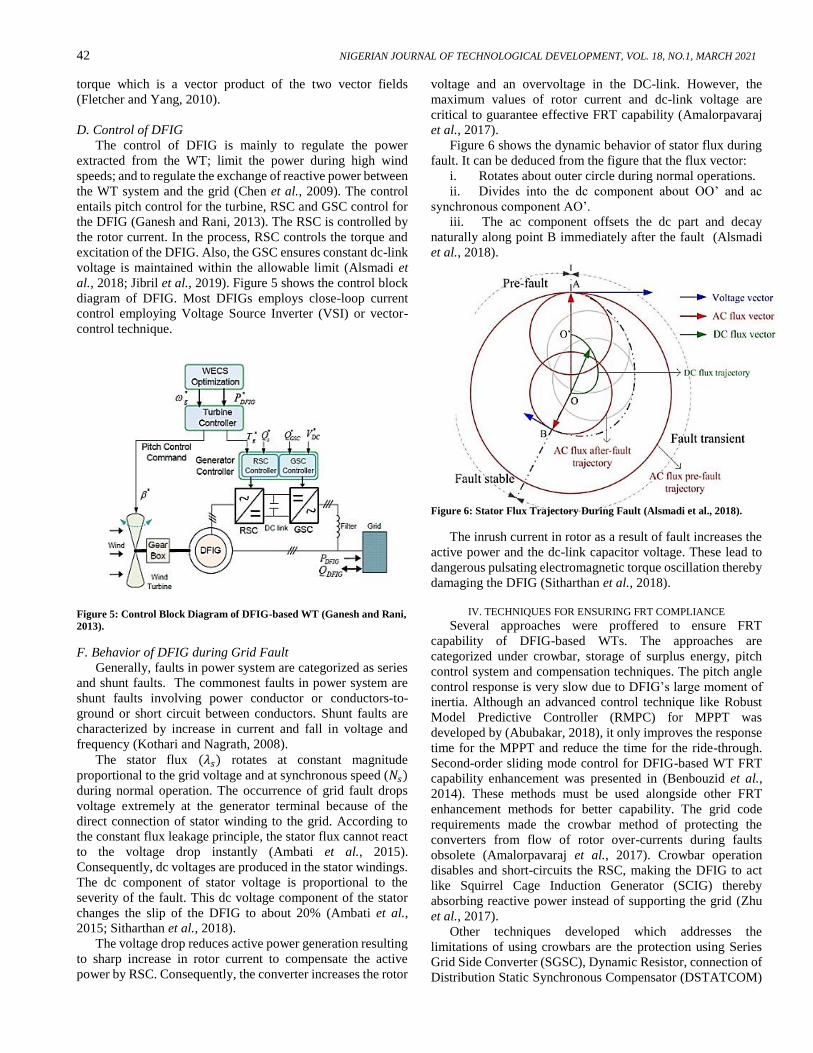
D. Control of DFIG
The control of DFIG is mainly to regulate the power
extracted from the WT; limit the power during high wind
speeds; and to regulate the exchange of reactive power between
the WT system and the grid (Chen et al., 2009). The control
entails pitch control for the turbine, RSC and GSC control for
the DFIG (Ganesh and Rani, 2013). The RSC is controlled by
the rotor current. In the process, RSC controls the torque and
excitation of the DFIG. Also, the GSC ensures constant dc-link
voltage is maintained within the allowable limit (Alsmadi et
al., 2018; Jibril et al., 2019). Figure 5 shows the control block
diagram of DFIG. Most DFIGs employs close-loop current
control employing Voltage Source Inverter (VSI) or vector-
control technique.
Figure 5: Control Block Diagram of DFIG-based WT (Ganesh and Rani,
2013).
F. Behavior of DFIG during Grid Fault
Generally, faults in power system are categorized as series
and shunt faults. The commonest faults in power system are
shunt faults involving power conductor or conductors-to-
ground or short circuit between conductors. Shunt faults are
characterized by increase in current and fall in voltage and
frequency (Kothari and Nagrath, 2008).
The stator flux (𝜆𝑠) rotates at constant magnitude
proportional to the grid voltage and at synchronous speed (𝑁𝑠)
during normal operation. The occurrence of grid fault drops
voltage extremely at the generator terminal because of the
direct connection of stator winding to the grid. According to
the constant flux leakage principle, the stator flux cannot react
to the voltage drop instantly (Ambati et al., 2015).
Consequently, dc voltages are produced in the stator windings.
The dc component of stator voltage is proportional to the
severity of the fault. This dc voltage component of the stator
changes the slip of the DFIG to about 20% (Ambati et al.,
2015; Sitharthan et al., 2018).
The voltage drop reduces active power generation resulting
to sharp increase in rotor current to compensate the active
power by RSC. Consequently, the converter increases the rotor
voltage and an overvoltage in the DC-link. However, the
maximum values of rotor current and dc-link voltage are
critical to guarantee effective FRT capability (Amalorpavaraj
et al., 2017).
Figure 6 shows the dynamic behavior of stator flux during
fault. It can be deduced from the figure that the flux vector:
i. Rotates about outer circle during normal operations.
ii. Divides into the dc component about OO’ and ac
synchronous component AO’.
iii. The ac component offsets the dc part and decay
naturally along point B immediately after the fault (Alsmadi
et al., 2018).
Figure 6: Stator Flux Trajectory During Fault (Alsmadi et al., 2018).
The inrush current in rotor as a result of fault increases the
active power and the dc-link capacitor voltage. These lead to
dangerous pulsating electromagnetic torque oscillation thereby
damaging the DFIG (Sitharthan et al., 2018).
IV. TECHNIQUES FOR ENSURING FRT COMPLIANCE
Several approaches were proffered to ensure FRT
capability of DFIG-based WTs. The approaches are
categorized under crowbar, storage of surplus energy, pitch
control system and compensation techniques. The pitch angle
control response is very slow due to DFIG’s large moment of
inertia. Although an advanced control technique like Robust
Model Predictive Controller (RMPC) for MPPT was
developed by (Abubakar, 2018), it only improves the response
time for the MPPT and reduce the time for the ride-through.
Second-order sliding mode control for DFIG-based WT FRT
capability enhancement was presented in (Benbouzid et al.,
2014). These methods must be used alongside other FRT
enhancement methods for better capability. The grid code
requirements made the crowbar method of protecting the
converters from flow of rotor over-currents during faults
obsolete (Amalorpavaraj et al., 2017). Crowbar operation
disables and short-circuits the RSC, making the DFIG to act
like Squirrel Cage Induction Generator (SCIG) thereby
absorbing reactive power instead of supporting the grid (Zhu
et al., 2017).
Other techniques developed which addresses the
limitations of using crowbars are the protection using Series
Grid Side Converter (SGSC), Dynamic Resistor, connection of
Distribution Static Synchronous Compensator (DSTATCOM)
SHUAIBU et al: TECHNIQUES FOR ENSURING FAULT RIDE-THROUGH CAPABILITY OF DFIG WTS 43
*Corresponding author: [email protected] doi: http://dx.doi.org/10.4314/njtd.v18i1.6
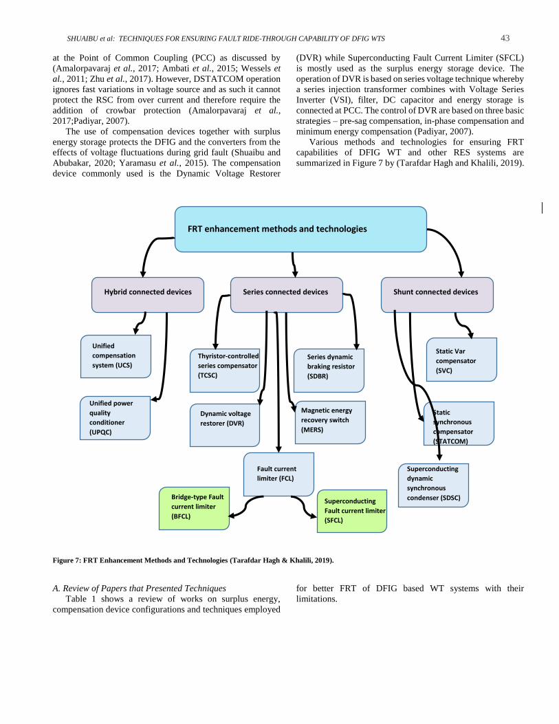
FRT enhancement methods and technologies
Hybrid connected devices Series connected devices Shunt connected devices
Unified
compensation
system (UCS)
Unified power
quality
conditioner
(UPQC)
Series dynamic
braking resistor
(SDBR)
Thyristor-controlled
series compensator
(TCSC)
Dynamic voltage
restorer (DVR)
Fault current
limiter (FCL)
Magnetic energy
recovery switch
(MERS)
Static Var
compensator
(SVC)
Static
synchronous
compensator
(STATCOM)
Superconducting
dynamic
synchronous
condenser (SDSC) Superconducting
Fault current limiter
(SFCL)
Bridge-type Fault
current limiter
(BFCL)
at the Point of Common Coupling (PCC) as discussed by
(Amalorpavaraj et al., 2017; Ambati et al., 2015; Wessels et
al., 2011; Zhu et al., 2017). However, DSTATCOM operation
ignores fast variations in voltage source and as such it cannot
protect the RSC from over current and therefore require the
addition of crowbar protection (Amalorpavaraj et al.,
2017;Padiyar, 2007).
The use of compensation devices together with surplus
energy storage protects the DFIG and the converters from the
effects of voltage fluctuations during grid fault (Shuaibu and
Abubakar, 2020; Yaramasu et al., 2015). The compensation
device commonly used is the Dynamic Voltage Restorer
(DVR) while Superconducting Fault Current Limiter (SFCL)
is mostly used as the surplus energy storage device. The
operation of DVR is based on series voltage technique whereby
a series injection transformer combines with Voltage Series
Inverter (VSI), filter, DC capacitor and energy storage is
connected at PCC. The control of DVR are based on three basic
strategies – pre-sag compensation, in-phase compensation and
minimum energy compensation (Padiyar, 2007).
Various methods and technologies for ensuring FRT
capabilities of DFIG WT and other RES systems are
summarized in Figure 7 by (Tarafdar Hagh and Khalili, 2019).
Figure 7: FRT Enhancement Methods and Technologies (Tarafdar Hagh & Khalili, 2019).
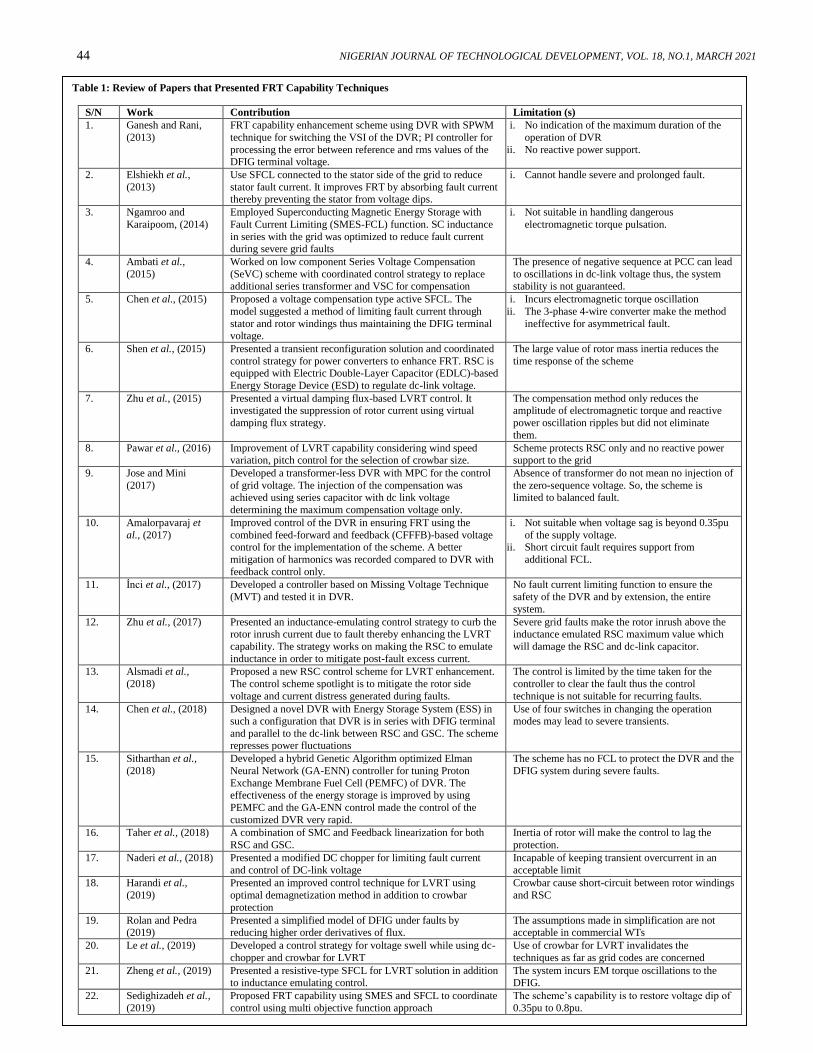
A. Review of Papers that Presented Techniques
Table 1 shows a review of works on surplus energy,
compensation device configurations and techniques employed
for better FRT of DFIG based WT systems with their
limitations.
44 NIGERIAN JOURNAL OF TECHNOLOGICAL DEVELOPMENT, VOL. 18, NO.1, MARCH 2021
Table 1: Review of Papers that Presented FRT Capability Techniques
S/N Work Contribution Limitation (s)
1. Ganesh and Rani,
(2013)
FRT capability enhancement scheme using DVR with SPWM
technique for switching the VSI of the DVR; PI controller for
processing the error between reference and rms values of the DFIG terminal voltage.
i. No indication of the maximum duration of the
operation of DVR
ii. No reactive power support.
2. Elshiekh et al.,
(2013)
Use SFCL connected to the stator side of the grid to reduce
stator fault current. It improves FRT by absorbing fault current thereby preventing the stator from voltage dips.
i. Cannot handle severe and prolonged fault.
3. Ngamroo and
Karaipoom, (2014)
Employed Superconducting Magnetic Energy Storage with
Fault Current Limiting (SMES-FCL) function. SC inductance
in series with the grid was optimized to reduce fault current during severe grid faults
i. Not suitable in handling dangerous
electromagnetic torque pulsation.
4. Ambati et al.,
(2015)
Worked on low component Series Voltage Compensation
(SeVC) scheme with coordinated control strategy to replace additional series transformer and VSC for compensation
The presence of negative sequence at PCC can lead
to oscillations in dc-link voltage thus, the system stability is not guaranteed.
5. Chen et al., (2015) Proposed a voltage compensation type active SFCL. The
model suggested a method of limiting fault current through
stator and rotor windings thus maintaining the DFIG terminal
voltage.
i. Incurs electromagnetic torque oscillation
ii. The 3-phase 4-wire converter make the method
ineffective for asymmetrical fault.
6. Shen et al., (2015) Presented a transient reconfiguration solution and coordinated
control strategy for power converters to enhance FRT. RSC is equipped with Electric Double-Layer Capacitor (EDLC)-based
Energy Storage Device (ESD) to regulate dc-link voltage.
The large value of rotor mass inertia reduces the
time response of the scheme
7. Zhu et al., (2015) Presented a virtual damping flux-based LVRT control. It investigated the suppression of rotor current using virtual
damping flux strategy.
The compensation method only reduces the amplitude of electromagnetic torque and reactive
power oscillation ripples but did not eliminate
them.
8. Pawar et al., (2016) Improvement of LVRT capability considering wind speed variation, pitch control for the selection of crowbar size.
Scheme protects RSC only and no reactive power support to the grid
9. Jose and Mini
(2017)
Developed a transformer-less DVR with MPC for the control
of grid voltage. The injection of the compensation was achieved using series capacitor with dc link voltage
determining the maximum compensation voltage only.
Absence of transformer do not mean no injection of
the zero-sequence voltage. So, the scheme is limited to balanced fault.
10. Amalorpavaraj et
al., (2017)
Improved control of the DVR in ensuring FRT using the
combined feed-forward and feedback (CFFFB)-based voltage control for the implementation of the scheme. A better
mitigation of harmonics was recorded compared to DVR with
feedback control only.
i. Not suitable when voltage sag is beyond 0.35pu
of the supply voltage. ii. Short circuit fault requires support from
additional FCL.
11. İnci et al., (2017) Developed a controller based on Missing Voltage Technique
(MVT) and tested it in DVR.
No fault current limiting function to ensure the
safety of the DVR and by extension, the entire
system.
12. Zhu et al., (2017) Presented an inductance-emulating control strategy to curb the rotor inrush current due to fault thereby enhancing the LVRT
capability. The strategy works on making the RSC to emulate
inductance in order to mitigate post-fault excess current.
Severe grid faults make the rotor inrush above the inductance emulated RSC maximum value which
will damage the RSC and dc-link capacitor.
13. Alsmadi et al.,
(2018)
Proposed a new RSC control scheme for LVRT enhancement.
The control scheme spotlight is to mitigate the rotor side
voltage and current distress generated during faults.
The control is limited by the time taken for the
controller to clear the fault thus the control
technique is not suitable for recurring faults.
14. Chen et al., (2018) Designed a novel DVR with Energy Storage System (ESS) in such a configuration that DVR is in series with DFIG terminal
and parallel to the dc-link between RSC and GSC. The scheme represses power fluctuations
Use of four switches in changing the operation modes may lead to severe transients.
15. Sitharthan et al.,
(2018)
Developed a hybrid Genetic Algorithm optimized Elman
Neural Network (GA-ENN) controller for tuning Proton
Exchange Membrane Fuel Cell (PEMFC) of DVR. The
effectiveness of the energy storage is improved by using
PEMFC and the GA-ENN control made the control of the
customized DVR very rapid.
The scheme has no FCL to protect the DVR and the
DFIG system during severe faults.
16. Taher et al., (2018) A combination of SMC and Feedback linearization for both
RSC and GSC.
Inertia of rotor will make the control to lag the
protection.
17. Naderi et al., (2018) Presented a modified DC chopper for limiting fault current
and control of DC-link voltage
Incapable of keeping transient overcurrent in an
acceptable limit
18. Harandi et al.,
(2019)
Presented an improved control technique for LVRT using
optimal demagnetization method in addition to crowbar
protection
Crowbar cause short-circuit between rotor windings
and RSC
19. Rolan and Pedra (2019)
Presented a simplified model of DFIG under faults by reducing higher order derivatives of flux.
The assumptions made in simplification are not acceptable in commercial WTs
20. Le et al., (2019) Developed a control strategy for voltage swell while using dc-
chopper and crowbar for LVRT
Use of crowbar for LVRT invalidates the
techniques as far as grid codes are concerned
21. Zheng et al., (2019) Presented a resistive-type SFCL for LVRT solution in addition to inductance emulating control.
The system incurs EM torque oscillations to the DFIG.
22. Sedighizadeh et al.,
(2019)
Proposed FRT capability using SMES and SFCL to coordinate
control using multi objective function approach
The scheme’s capability is to restore voltage dip of
0.35pu to 0.8pu.
SHUAIBU et al: TECHNIQUES FOR ENSURING FAULT RIDE-THROUGH CAPABILITY OF DFIG WTS 45
*Corresponding author: [email protected] doi: http://dx.doi.org/10.4314/njtd.v18i1.6
B. State of the Art Techniques for FRT Compliance
In view of the limitations with the reviewed works and the
quest for making the DFIG based WT systems contribute to
grid stability, there is need to develop a scheme for ensuring a
complete FRT capability. DVR is prone to damage by large
grid side fault current. This prompted the development of
various topologies and control strategies of DVR with FCL
capability (Jiang et al., 2018). In the event of short circuit, the
FCL must protect the grid and the equipment (Bacha et al.,
2008; Li et al., 2007). The FCL techniques are solid-state
FCLs, superconducting FCLs, resonance-type FCLs and
saturated core FCLs among others (Jiang et al., 2018).
Although SFCL with additional control features incur
electromagnetic torque oscillation to the entire system, the
methodology of incorporating the two models must ensure
limiting the oscillations for a better transient stability.
Therefore, the multi-functional DVR also called DVR-FCL is
proposed. The two methods of incorporating FCL to DVR are
improvement of topology and optimization of control scheme.
The FCLs are incorporated to protect the DVR and the DFIG
system from large fault currents. The requirements are fast
triggering, steady-state low impedance, high fault limiting
capability, fast recovery and high utilization efficiency.
V. CONCLUSION
A number of researches have been conducted towards
improving the DFIG’s FRT capability including control
strategy and additional hardware devices. This work has
presented a review on various techniques for FRT compliance
of DFIG-based WT system. The updates in requirements
necessitates the use of a scheme that will also ensure the
protection of converters from damages due to short-circuit
currents. For this reason, the methods of incorporating FCL to
DVR through improvement of topology and optimization of
control scheme are preferred. Furthermore, multi-functional
compensation devices can mitigate voltage sag and swell, limit
fault current and minimize power frequency variation. Finally,
the improvement of functionality of the traditional DVR
topology is a better alternative than installing two protective
devices separately in terms of cost and complexity to the entire
power system.
REFERENCES
Abubakar, A. S.; Y. Sha’aban; Y. Jibril; and B.
Jimoh. (2018). Development of a Multiple Model Predictive
Control for DFIG Based Wind Energy Conversion System.
Journal of Engineering Research, 23(1), 1-12.
Abubakar, A. S., (2018). Development of a Maximum
Power Point Tracking Scheme for DFIG Based Wind Turbine
using a Robust Model Predictive Control. (Ph.D), Ahmadu
Bello University Zaria, School of Postgraduate Studies.
Abubakar, A. S., (2019). Development of a Benchmark
Controller using Gain Scheduled PI for DFIG Based Wind
Turbine System. Paper presented at the ABUNEC, Zaria.
Agalar, S.; and Y. A. Kaplan. (2018). Power quality
improvement using STS and DVR in wind energy system.
Renewable energy, 118, 1031-1040.
Alaraifi, S.; A. Moawwad; M. S. El Moursi; and V.
Khadkikar. (2013). Voltage booster schemes for fault ride-
through enhancement of variable speed wind turbines. IEEE
Transactions on Sustainable Energy, 4(4), 1071-1081.
Alsmadi, Y. M.; L. Xu; F. Blaabjerg; A. P. Ortega; A.
Y. Abdelaziz; A. Wang; and Z. Albataineh. (2018). Detailed
Investigation and Performance Improvement of the Dynamic
Behavior of Grid-Connected DFIG-Based Wind Turbines
under LVRT Conditions. IEEE Transactions on Industry
Applications.
Amalorpavaraj, R. A. J.; P. Kaliannan; S.
Padmanaban; U. Subramaniam; and V. K.
Ramachandaramurthy. (2017). Improved fault ride through
capability in dfig based wind turbines using dynamic voltage
restorer with combined feed-forward and feed-back control.
IEEE Access, 5, 20494-20503.
Ambati, B. B.; P. Kanjiya; and V. Khadkikar. (2015). A low component count series voltage compensation scheme
for DFIG WTs to enhance fault ride-through capability. IEEE
Transactions on Energy Conversion, 30(1), 208-217.
Bacha, S.; D. Frey; J.-L. Schanen; E. Lepelleter; P.-
O. Jeannin; and R. Caire. (2008). Short-circuit limitation
thanks to a series connected VSC. Paper presented at the
Twenty-Third Annual IEEE Applied Power Electronics
Conference and Exposition, 2008.
Benbouzid, M.; B. Beltran; Y. Amirat; G. Yao; J.
Han; and H. Mangel. (2014). Second-order sliding mode
control for DFIG-based wind turbines fault ride-through
capability enhancement. ISA transactions, 53(3), 827-833.
Bhandare, A. M.; K. Jadhav; and M. Ghat. (2013). Performance of power coefficent and power with respect to
variable wind speed. Paper presented at the 2013 International
Conference on Energy Efficient Technologies for
Sustainability.
Chen, L.; F. Zheng; C. Deng; Z. Li; and F. Guo.
(2015). Fault ride-through capability improvement of DFIG-
based wind turbine by employing a voltage-compensation-type
active SFCL. Canadian Journal of Electrical and Computer
Engineering, 38(2), 132-142.
Chen, Z.; J. M. Guerrero; and F. Blaabjerg. (2009).
A review of the state of the art of power electronics for wind
turbines. IEEE Transactions on power electronics, 24(8), 1859-
1875.
Elshiekh, M. E.; D.-E. A. Mansour; and A. M. Azmy.
(2013). Improving fault ride-through capability of DFIG-based
wind turbine using superconducting fault current limiter. IEEE
transactions on Applied Superconductivity, 23(3), 5601204-
5601204.
Esch, J., (2015). High-power wind energy conversion
systems: State-of-the-art and emerging technologies.
Proceedings of the IEEE, 103(5), 736-739.
Fletcher, J. and Yang, J. (2010). Introduction to the
doubly-fed induction generator for wind power applications
Paths to sustainable energy: InTech.
Ganesh, N. and Rani, P. U. (2013). Fault-Ride Through
of a DFIG Wind Turbine using a Dynamic Voltage Restorer
during Symmetrical and Asymmetrical Grid Faults. 1(4), 2320-
8945.

46 NIGERIAN JOURNAL OF TECHNOLOGICAL DEVELOPMENT, VOL. 18, NO.1, MARCH 2021
Gardner, P.; G. Andrew; F. H. Lars; M. Colin; and
Z. Arthouros. (2012). Wind energy-the facts: a guide to the
technology, economics and future of wind power: Routledge.
Giddey, S.; S. P. Badwal; and H. Ju. (2019). Polymer
Electrolyte Membrane Technologies Integrated With
Renewable Energy for Hydrogen Production Current Trends
and Future Developments on (Bio-) Membranes (pp. 235-259):
Elsevier.
Ibrahim, A. O.; T. H. Nguyen; D.-C. Lee; and S.-C.
Kim. (2011). A fault ride-through technique of DFIG wind
turbine systems using dynamic voltage restorers. IEEE
Transactions on Energy Conversion, 26(3), 871-882.
İnci, M.; M. Büyük; A. Tan; K. Ç. Bayındır; and M.
Tümay. (2017). MVT controlled voltage restorer for fault-ride
through capability. Paper presented at the 10th International
Conference on Electrical and Electronics Engineering
(ELECO), 2017.
Jiang, F.; Y. Li; C. Tu; Q. Guo; and H. Li. (2018). A
review of series voltage source converter with fault current
limiting function. Chinese Journal of Electrical Engineering,
4(1), 36-44.
Jibril, Y.; G. Olarinoye; A. Abubakar; I.
Abdulwahab; and O. Ajayi. (2019). Control Methods Used
In Wind Energy Conversion System: A Review. ATBU
Journal of Science, Technology and Education, 7(2), 53-59.
Karakasis, N.; E. Tsioumas; N. Jabbour; A. M. Bazzi;
and C. Mademlis. (2018). Optimal Efficiency Control in a
Wind System with Doubly Fed Induction Generator. IEEE
Transactions on power electronics.
Kothari, D. and Nagrath, I. (2008). Power system
engineering: Tata McGraw-Hill New Delhi.
Li, Y. W.; D. M. Vilathgamuwa; P. C. Loh; and F.
Blaabjerg. (2007). A dual-functional medium voltage level
DVR to limit downstream fault currents. IEEE Transactions on
power electronics, 22(4), 1330-1340.
Long, T.; S. Shao; P. Malliband; E. Abdi; and R. A.
McMahon. (2013). Crowbarless fault ride-through of the
brushless doubly fed induction generator in a wind turbine
under symmetrical voltage dips. IEEE Transactions on
Industrial Electronics, 60(7), 2833-2841.
Ngamroo, I.; and T. Karaipoom. (2014). Improving
low-voltage ride-through performance and alleviating power
fluctuation of DFIG wind turbine in DC microgrid by optimal
SMES with fault current limiting function. IEEE transactions
on Applied Superconductivity, 24(5), 1-5.
Padiyar, K., (2007). FACTS controllers in power
transmission and distribution: New Age International.
Pawar, S.; A. Jain; and J. Patil. (2016). Increasing low
voltage ride through capability of doubly fed induction
generator in wind energy transfer system during grid fault.
Pioro, I.; R. Duffey; P. Kirillov; R. Pioro; A.
Zvorykin; and R. Machrafi. (2019). Current Status and
Future Developments in Nuclear-Power Industry of the World.
Journal of Nuclear Engineering and Radiation Science, 5(2),
024001.
Rahimi, M. and Parniani, M. (2010). Efficient control
scheme of wind turbines with doubly fed induction generators
for low-voltage ride-through capability enhancement. IET
Renewable Power Generation, 4(3), 242-252.
Shehu, A. F.; A. S. Abubakar; S. Musayyibi; and K.
Idris. (2019). Doubly fed Induction Generator Based Wind
Energy Conversion System: A Review. JOURnal of Science
Technology and Education, 7(3), 145-150.
Shen, Y.-W.; D.-P. Ke; W. Qiao; Y.-Z. Sun; D. S.
Kirschen; and C. Wei. (2015). Transient reconfiguration and
coordinated control for power converters to enhance the LVRT
of a DFIG wind turbine with an energy storage device. IEEE
Transactions on Energy Conversion, 30(4), 1679-1690.
Shuaibu, M. and Abubakar, A. S. (2020). An
Improved Dynamic Voltage Restorer Model for Ensuring Fault
Ride-Through Capability of DFIG-based Wind Turbine
Systems. ELEKTRIKA-Journal of Electrical Engineering,
19(1), 9-16.
Sitharthan, R.; C. Sundarabalan; K. Devabalaji; S. K.
Nataraj; and M. Karthikeyan. (2018). Improved fault ride
through capability of DFIG-wind turbines using customized
dynamic voltage restorer. Sustainable Cities and Society, 39,
114-125.
Tarafdar Hagh, M. and Khalili, T. (2019). A review
of fault ride through of PV and wind renewable energies in grid
codes. International Journal of Energy Research, 43(4), 1342-
1356.
Wessels, C.; F. Gebhardt; and F. W. Fuchs. (2011).
Fault ride-through of a DFIG wind turbine using a dynamic
voltage restorer during symmetrical and asymmetrical grid
faults. IEEE Transactions on power electronics, 26(3), 807-
815.
Yang, L.; Z. Xu; J. Ostergaard; Z. Y. Dong; and K.
P. Wong. (2012). Advanced control strategy of DFIG wind
turbines for power system fault ride through. IEEE
Transactions on power systems, 27(2), 713-722.
Yaramasu, V.; B. Wu; P. C. Sen; S. Kouro; and M.
Narimani. (2015). High-power wind energy conversion
systems: State-of-the-art and emerging technologies.
Proceedings of the IEEE, 103(5), 740-788.
Zhu, D.; X. Zou; L. Deng; Q. Huang; S. Zhou; and Y.
Kang. (2017). Inductance-emulating control for DFIG-based
wind turbine to ride-through grid faults. IEEE Transactions on
power electronics, 32(11), 8514-8525.
Zhu, R.; Z. Chen; X. Wu; and F. Deng. (2015). Virtual
damping flux-based LVRT control for DFIG-based wind
turbine. IEEE Transactions on Energy Conversion, 30(2), 714-
725.