industrie line - domi.sytes.netdomi.sytes.net/acdceng.pdf · electric shock electric shock can ......
TRANSCRIPT
MANU.115.M.ACDC.00
INDUSTRIE LINE
WIG 160 AC/DC WIG 200 AC/DC
USER MANUAL
2
TEC.LA S.r.l. thanks you for having chosen its welding machine, built with the principles of
safety and reliability. The quality materials used in building the machines ensure total reliability and ease of
maintenance.
We recommend reading the manual before connecting the system to the mains.
DECLARATION OF CE CONFORMITY MANUFACTURER TEC.LA. S.r.l. Via Castel Morrone n. 15/c 16161 GENOVA – ITALIA
DECLARES UNDER ITS SOLE RESPONSIBILITY THAT THE PRODUCTS LISTED BELOW, HAVING THE
TRADE MARK:
MODEL: WIG 160 AC-DC WIG 200 AC-DC SERIAL NUMBER:
REFERRING TO DELIVERIES STARTING JANUARY THE 1ST 2005, IS
IN CONFORMITY WITH THE PROTECTION REQUIREMENTS SET BY DIRECTIVES 89/336 EEC, 92/31 EEC AND 93/68 EEC REGARDING ELECTRO MAGNETIC COMPATIBILITY (EMC). IN PARTICULAR IT CONFORMS WITH THE TECHNICAL REQUIREMENTS OF THE EN 50199, EN 60974-1 STANDARDS AND IS TO BE USED IN ALL INDUSTRIAL BUILDINGS, NOT FOR HOUSEHOLD USE. GENOVA, JANUARY THE 1ST, 2005
MANAGING DIRECTOR CARLO CURLETTO
3
Valued Customer, Hoping you will find our product to your satisfaction, we welcome you to our family, informing you that the ERGUS marked machines have been ISO 9000:2001 certified, thus guaranteeing greater product reliability and quality.
TABLE OF CONTENTS
GENERAL SAFETY INFORMATION .......................................................................................... 5
DESCRIPTION OF POWER SOURCE ........................................................................................ 7
1. Placing the equipment .............................................................................................................. 7
2. Receipt of materials ................................................................................................................. 7
3. Front panel controls ................................................................................................................. 8
INSTALLATION AND USE .......................................................................................................... 9
INSTALLATION OF ELECTRODE MACHINE .......................................................................... 10
1. Electrode welding ................................................................................................................... 11
2. Electrode welding defects–troubleshooting ............................................................................ 12
INSTALLATION OF MACHINE IN TIG HF ................................................................................ 13
1.TIG welding ............................................................................................................................. 15
2.TIG welding defects – troubleshooting .................................................................................... 20
WHAT IF THE INVERTER DOESN’T WORK? ......................................................................... 21
AVAILABLE ACCESSORIES ................................................................................................... 22
1. Pulse unit ............................................................................................................................... 22
2. Foot control ............................................................................................................................ 22
3. Remote control ....................................................................................................................... 22
4. Other accessories .................................................................................................................. 22
TECHNICAL DATA ................................................................................................................... 23

4
FEATURES ................................................................................................................................ 23
BLOCK DIAGRAM .................................................................................................................... 24
REMOTE CONTROL CONNECTION DIAGRAM ...................................................................... 26
SPARE PARTS LIST ................................................................................................................. 27

5
GENERAL SAFETY INFORMATION
Electric shock ELECTRIC SHOCK CAN KILL.
Do not touch the parts under high voltage;
Disconnect the power supply from mains before any intervention;
Operator must be insulated from the weld piece and from the ground, using insulated gloves and clothing;
Do not work with damaged or poorly connected cables or with slack cable clamps;
Keep work clothing and your body, dry;
Do not work in moist or wet areas;
Do not lean against the weld pieces;
Protect the power source with a suitable circuit breaker, placed near the welder if possible;
Do not use the machine if any of its protection parts have been removed;
Make sure that the mains in use is earthed. Explosions
Do not weld above or near containers under high pressure;
Do not weld recipients that contain fuel or inflammables;
Do not weld in areas containing explosive dusts, gases or vapours;
Always use a pressure gauge to connect the machine gas hose to the bottle;
Do not use damaged or leaking bottles;
Do not use bottles that do not show what kind of gas they contain;
Do not expose bottles to sources of excessive heat;
Never mix the gas inside bottles;
Have always refilled bottles by specialized companies;
Avoid accidental contact between bottles and the electrode or other parts under voltage;
Replace gas hoses that show damage;
Keep pressure reducer efficient;
Use only pressure reducers manufactured for the specific gas. Fire
Avoid flames being generated by sparks, slag and incandescent materials;
Make sure that fire extinguishing devices are available near the work area;
Remove inflammable and combustible materials from the area. Burns
Protect the body from burns and ultraviolet radiations by wearing protective flameproof clothing (gloves – headwear – shoes – helmets, etc.);
Wear a welding helmet;
Keep the electrode or torch tip away from your body and other people’s bodies;
Make sure that there is first aid equipment near the work area;
Do not wear contact lenses, the intense heat of the arc could glue them to the cornea;
Replace mask glass if it is damaged or not suited to the specific welding job;
Wait for the welded parts to cool completely before touching them with your hands. Fumes Welding produces fumes and harmful metallic dusts, therefore;
If working in closed areas, use exhaust fans;
Clean the weld piece if solvents or other materials that can release toxic gases are present on its surface;
Do not weld metals covered with or containing lead, cadmium, graphite, zinc, chrome, mercury, if there is not an adequate exhaust fan;
WARNING: do not use oxygen for ventilation!!! Radiation The welding arc produces radiation that can damage eyes and burn the skin. The welding arc is considered dangerous up to a distance of 15m (50 ft). Use suitable protection.
6
Noise The welding arc respects current legislation on noise levels (not exceeding 80db); Protective ear plugs or muffs must be worn to avoid damage when working overhead or in small areas. Electromagnetic disturbance The power source respects legislation regarding electromagnetic disturbances and is suitable for work in industrial surroundings. However, it is necessary to remember and take necessary provisions if there are disturbances to:
Data transmission systems;
Communication devices;
Switch board controls;
Safety equipment;
Calibration and measurement instruments. Pacemaker wearers The magnetic fields coming from high votage or frequency can interfere with pacemakers. Pacemaker wearers must consult their doctor before using this type of equipment or working in the area where it is present. Moving parts Keep all protective doors and coverings in place; Keep hands, hair and clothing away from moving parts (fan, rotator, wire feeder for MIG machines).
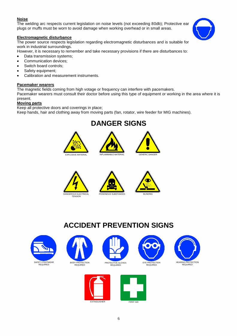
DANGER SIGNS
ACCIDENT PREVENTION SIGNS
GENERIC DANGER
EXPLOSIVE MATERIAL
INFLAMMABLE MATERIAL
DANGEROUS ELECTRICAL
TENSION
POISONOUS SUBSTANCES
BLINDING
SAFETY FOOTWEAR
REQUIRED
BODY PROTECTION
REQUIRED
PROTECTIVE GLOVES
REQUIRED
EYE PROTECTION
REQUIRED
HEARING PROTECTION
REQUIRED
EXTINGUISHER
FIRST AID
7
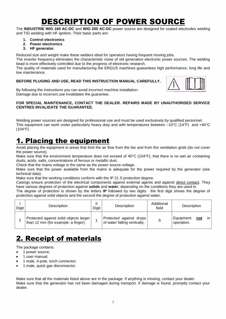
DESCRIPTION OF POWER SOURCE
The INDUSTRIE WIG 160 AC-DC and WIG 200 AC-DC power source are designed for coated electrodes welding and TIG welding with HF ignition. Their basic parts are:
1. Control electronics 2. Power electronics 3. HF generator.
Reduced size and weight make these welders ideal for operators having frequent moving jobs. The inverter frequency eliminates the characteristic noise of old generation electronic power sources. The welding bead is more effectively controlled due to the progress of electronic research. The quality of materials used for manufacturing the ERGUS machines guarantees high performance, long life and low maintenance. BEFORE PLUGING AND USE, READ THIS INSTRUCTION MANUAL CAREFULLY. By following the instructions you can avoid incorrect machine installation. Damage due to incorrect use invalidates the guarantee. FOR SPECIAL MAINTENANCE, CONTACT THE DEALER. REPAIRS MADE BY UNAUTHORISED SERVICE CENTRES INVALIDATE THE GUARANTEE. Welding power sources are designed for professional use and must be used exclusively by qualified personnel. This equipment can work under particularly heavy duty and with temperatures between –10°C (14°F) and +40°C (104°F).
1. Placing the equipment
Avoid placing the equipment in areas that limit the air flow from the fan and from the ventilation grids (do not cover the power source). Make sure that the environment temperature does not exceed of 40°C (104°F), that there is no wet air containing dusts, acids, salts, concentrations of ferrous or metallic dust. Check that the mains voltage is the same as the power source voltage. Make sure that the power available from the mains is adequate for the power required by the generator (see technical data). Make sure that the working conditions conform with the IP 21 S protection degree. Casings ensure protection of the electrical components against external agents and against direct contact. They have various degrees of protection against solids and water, depending on the conditions they are used in. The degree of protection is shown by the letters IP followed by two digits: the first digit shows the degree of protection against solid objects and the second the degree of protection against water.
I Digit
Description II
Digit Description
Additional field
Description
2 Protected against solid objects larger than 12 mm (for example: a finger).
1 Protected against drops of water falling vertically.
S Equipment not in operation.
2. Receipt of materials
The package contains:
1 power source;
1 user manual;
1 male, 4-pole, torch connector;
1 male, quick gas disconnector. Make sure that all the materials listed above are in the package. If anything is missing, contact your dealer. Make sure that the generator has not been damaged during transport. If damage is found, promptly contact your dealer.
8
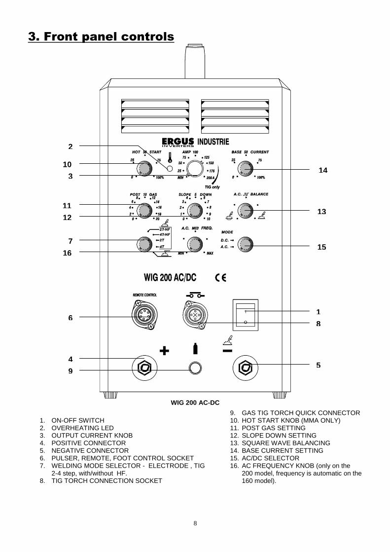
3. Front panel controls
WIG 200 AC-DC
1. ON-OFF SWITCH 2. OVERHEATING LED 3. OUTPUT CURRENT KNOB 4. POSITIVE CONNECTOR 5. NEGATIVE CONNECTOR 6. PULSER, REMOTE, FOOT CONTROL SOCKET 7. WELDING MODE SELECTOR - ELECTRODE , TIG
2-4 step, with/without HF. 8. TIG TORCH CONNECTION SOCKET
9. GAS TIG TORCH QUICK CONNECTOR 10. HOT START KNOB (MMA ONLY) 11. POST GAS SETTING 12. SLOPE DOWN SETTING 13. SQUARE WAVE BALANCING 14. BASE CURRENT SETTING 15. AC/DC SELECTOR 16. AC FREQUENCY KNOB (only on the
200 model, frequency is automatic on the 160 model).
9
6
16
7
12
11
3
10
5
8
1
15
13
14
4
2
9
INSTALLATION AND USE
Machine installation must be done by qualified personnel. All connections must be done in conformity with current specifications and with respect for industrial accident prevention regulations. Before connecting the power source to the mains, check that it is between 210 V and 250 V. Mains receptacle must be earthed. Tables of lengths and sections Mains used must always supply the required power. In some applications extension cables are necessary to reach the work area. To ensure maximum power source output, abide by the following tables showing the section of the extention cables vs. length.
WELDING STICK OF 3,25 MM (1/8”) (140A-160 A) and TIG WELDING OF 200 A
10 mt (33 ft) 2,5 mmq (12 AWG)
20 mt (66 ft) 4 mmq (10 AWG)
30 mt (99 ft) 6 mmq (9 AWG)
NOTE: For different lengths, use a proportional section size.
10
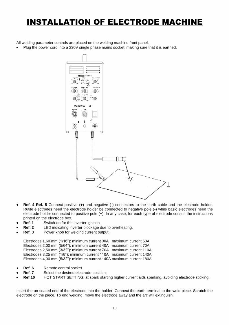
INSTALLATION OF ELECTRODE MACHINE
All welding parameter controls are placed on the welding machine front panel.
Plug the power cord into a 230V single phase mains socket, making sure that it is earthed.
Ref. 4 Ref. 5 Connect positive (+) and negative (-) connectors to the earth cable and the electrode holder.
Rutile electrodes need the electrode holder be connected to negative pole (-) while basic electrodes need the electrode holder connected to positive pole (+). In any case, for each type of electrode consult the instructions printed on the electrode box.
Ref. 1 Switch-on for the inverter ignition.
Ref. 2 LED indicating inverter blockage due to overheating.
Ref. 3 Power knob for welding current output.
Electrodes 1,60 mm (1/16”): minimum current 30A maximum current 50A Electrodes 2,00 mm (5/64”): minimum current 40A maximum current 70A Electrodes 2,50 mm (3/32”): minimum current 70A maximum current 110A Electrodes 3,25 mm (1/8”): minimum current 110A maximum current 140A Electrodes 4,00 mm (5/32”): minimum current 140A maximum current 180A
Ref. 6 Remote control socket.
Ref. 7 Select the desired electrode position;
Ref.10 HOT START SETTING: at spark starting higher current aids sparking, avoiding electrode sticking. Insert the un-coated end of the electrode into the holder. Connect the earth terminal to the weld piece. Scratch the electrode on the piece. To end welding, move the electrode away and the arc will extinguish.
11
1. Electrode welding
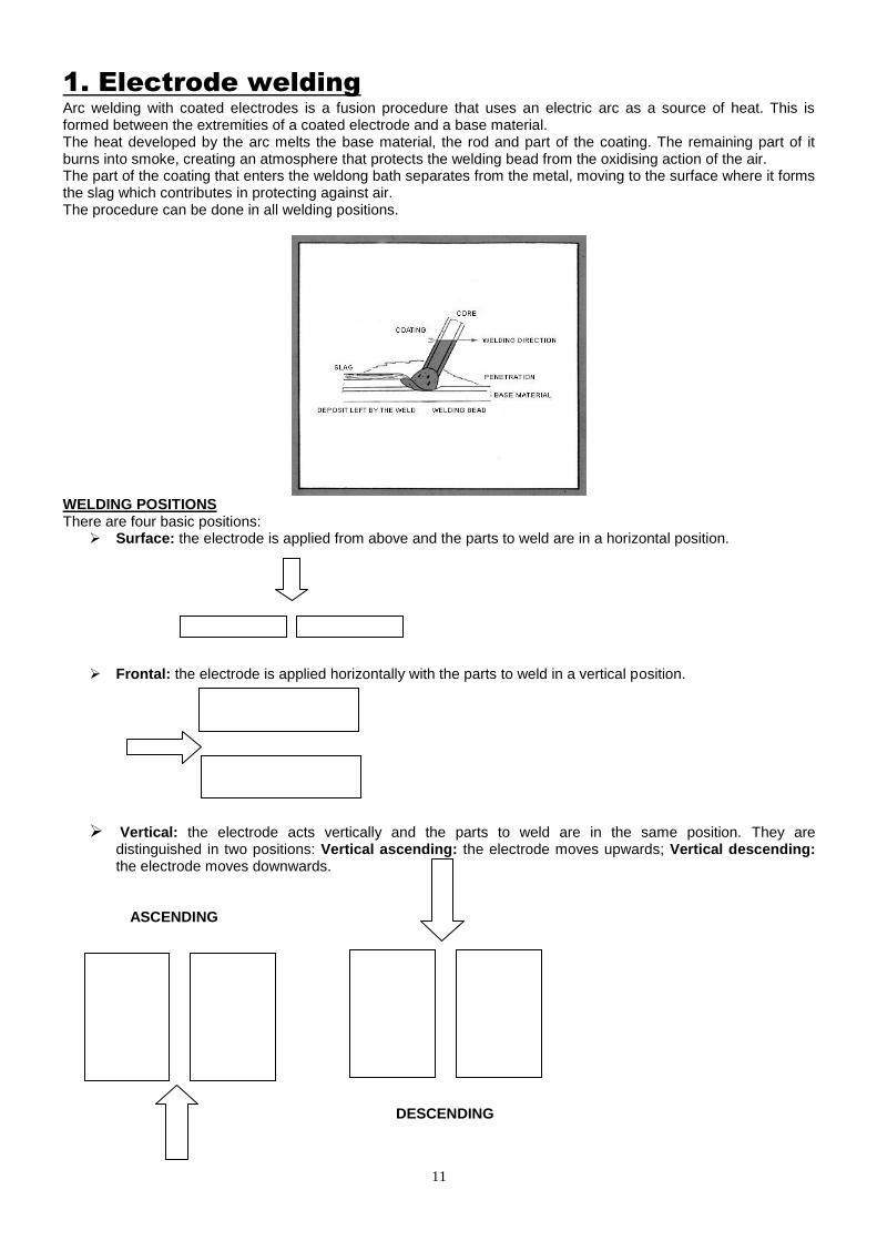
Arc welding with coated electrodes is a fusion procedure that uses an electric arc as a source of heat. This is formed between the extremities of a coated electrode and a base material. The heat developed by the arc melts the base material, the rod and part of the coating. The remaining part of it burns into smoke, creating an atmosphere that protects the welding bead from the oxidising action of the air. The part of the coating that enters the weldong bath separates from the metal, moving to the surface where it forms the slag which contributes in protecting against air. The procedure can be done in all welding positions.
WELDING POSITIONS There are four basic positions: Surface: the electrode is applied from above and the parts to weld are in a horizontal position.
Frontal: the electrode is applied horizontally with the parts to weld in a vertical position.
Vertical: the electrode acts vertically and the parts to weld are in the same position. They are distinguished in two positions: Vertical ascending: the electrode moves upwards; Vertical descending: the electrode moves downwards.
ASCENDING
DESCENDING

12
NB: Descending welding needs a quick movement, while ascending welding needs a slow movement which heats the material to be welded. Overhead: the electrode works upwards, while the parts to weld are in a horizontal position.
FOR OPTIMAL WELDING ON MATERIALS OF CONSISTENT THICKNESS, THE EDGES TO BE JOINED SHOULD BE PREPARED FOR WELDING BEFORE PROCEEDING.
2. Electrode welding defects–troubleshooting
DEFECT POSSIBLE CAUSES REMEDIES
1. Air bubbles in the bead (porosity).
A. Wet electrodes. B. Welding current to high. C. Greasy or painted Surfaces
A. Dry electrodes before use. B. Reduce welding current. C. Clean joints before welding them.
2. Visible cracks in the bead immediately after solidification.
A. Joints too rigid. B. Welding throat too thin. C. Cooling too quick.
A. Eliminate tension problems due to the shape of joints.
B. Reduce welding speed to allow for a thicker deposit.
C. Pre-heat the piece and cool it more slowly.
3. Fissure due to slight filling of the split.
A. Welding current too low. B. Electrode too big for the joint. C. Insufficient split. D. Incorrect welding sequence.
A. Increase welding current. B. Use electrodes of a smaller diameter. C. Enlarge split. D. Place the pieces in a correct sequence.
4. Portions of the welded piece not melted with the sheet metal or with the joint.
A. Electrodes too thin for the piece to be welded.
B. Welding current too low. C. Electrode used with incorrect
slope. D. Weldingf speed too fast. E. Slag or dirt on the surface of
the piece.
A. Use electrodes of a larger diameter and pre-heat the piece.
B. Increase welding current. C. Correct the welding angle towards the
base plate. D. Reduce the welding speed. E. Clean the surface before welding.
5. Non metallic material trapped in the weld bead (slag included).
A. Particles trapped in the lower layers of the preceding passages.
B. Joint prepared too tight. C. An irregular deposit helps the
slag to stay trapped. D. Slight penetration with slag
trapped under the welding bath.
E. Rust or chips prevent total melting.
F. Wrong electrode for the welding position.
A. In situations of slight base welding, clean slag and pass on the base again with an electrode of a smaller diameter.
B. Guarantee enough space for slag cleaning.
C. If necessary, grind the slight or the irregular part.
D. Remove all slag from corners. Use smaller electrodes with higher current for suitable penetration.
E. Clean the joint before welding. F. Use electrodes suited to the welding
position, otherwise it will be difficult to remove the slag.
13
INSTALLATION OF MACHINE IN TIG HF
DC - DIRECT CURRENT
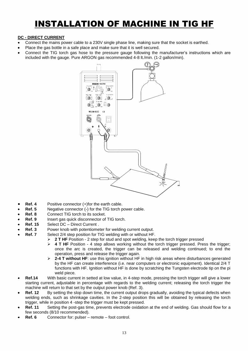
Connect the mains power cable to a 230V single phase line, making sure that the socket is earthed.
Place the gas bottle in a safe place and make sure that it is well secured.
Connect the TIG torch gas hose to the pressure gauge following the manufacturer’s instructions which are included with the gauge. Pure ARGON gas recommended 4-8 lt./min. (1-2 gallon/min).
Ref. 4 Positive connector (+)for the earth cable. Ref. 5 Negative connector (-) for the TIG torch power cable.
Ref. 8 Connect TIG torch to its socket.
Ref. 9 Insert gas quick disconnector of TIG torch.
Ref. 15 Select DC – Direct Current .
Ref. 3 Power knob with potentiometer for welding current output.
Ref. 7 Select 2/4 step position for TIG welding with or without HF. 2 T HF Position - 2 step for stud and spot welding, keep the torch trigger pressed 4 T HF Position - 4 step allows working without the torch trigger pressed. Press the trigger;
once the arc is created, the trigger can be released and welding continued; to end the operation, press and release the trigger again.
2-4 T without HF: use this ignition without HF in high risk areas where disturbances generated by the HF can create interference (i.e. near computers or electronic equipment). Identical 2/4 T functions with HF. Ignition without HF is done by scratching the Tungsten electrode tip on the pi weld piece.
Ref.14 With basic current in setted at low value, in 4-step mode, pressing the torch trigger will give a lower starting current, adjustable in percentage with regards to the welding current; releasing the torch trigger the machine will return to that set by the output power knob (Ref. 3).
Ref. 12 By setting the slop down time, the current output drops gradually, avoiding the typical defects when welding ends, such as shrinkage cavities. In the 2-step position this will be obtained by releasing the torch trigger, while in position 4 -step the trigger must be kept pressed.
Ref. 11 Setting the post-gas time, prevents electrode oxidation at the end of welding. Gas should flow for a few seconds (8/10 recommended).
Ref. 6 Connector for: pulser – remote – foot control.
14
AC - ALTERNATING CURRENT
Ref. 4 Positive connector (+)for the earth cable. Ref. 5 Negative connector (-) for the TIG torch power cable.
Ref. 8 Connect TIG torch to its socket.
Ref. 9 Insert gas quick disconnector of TIG torch.
Ref. 15 Select AC – Alternating Current .
Ref. 3 Power knob with potentiometer for welding current output.
Ref. 7 Select 2 - 4 step position for TIG welding with or without HF. 2 T HF Position - 2 step for stud and spot welding, keep the torch trigger pressed 4 T HF Position - 4 step allows working without the torch trigger pressed. Press the trigger;
once the arc is created, the trigger can be released and welding continued; to end the operation, press and release the trigger again.
2- 4 T without HF: use this ignition without HF in high risk areas where disturbances generated by the HF can create interference (i.e. near computers or electronic equipment). Identical 2/4 T functions with HF. Ignition without HF is done by scratching the Tungsten electrode tip on the pi weld piece.
Ref.14 With basic current in setted at low value, in 4-step mode, pressing the torch trigger will give a lower starting current, adjustable in percentage with regards to the welding current; releasing the torch trigger the machine will return to that set by the output power knob (Ref. 3).
Ref. 11 Setting the post-gas time, prevents electrode oxidation at the end of welding. Gas should flow for a few seconds (8/10 recommended).
Ref. 13 Setting the balancing knob with the pointer in a central position, the arc is balanced; turning anti-clockwise will give more penetration of the welding bead, turning clockwise will give cleaning cleaning of the welding bead.
Ref. 12 By setting the slop down time, the current output drops gradually, avoiding the typical defects when welding ends, such as shrinkage cavities. In the 2-step position this will be obtained by releasing the torch trigger, while in position 4 -step the trigger must be kept pressed.
Ref. 6 Connector for: pulser – remote – foot control.
15
1.TIG welding
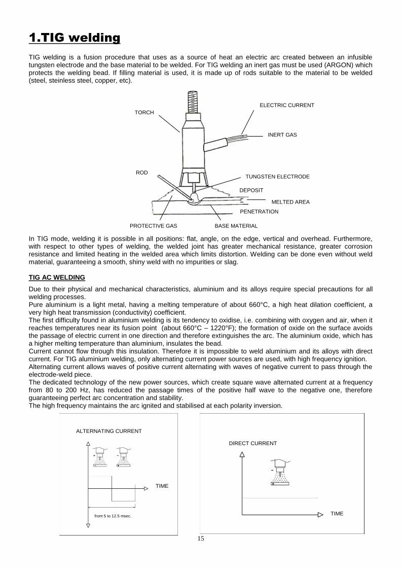
TIG welding is a fusion procedure that uses as a source of heat an electric arc created between an infusible tungsten electrode and the base material to be welded. For TIG welding an inert gas must be used (ARGON) which protects the welding bead. If filling material is used, it is made up of rods suitable to the material to be welded (steel, steinless steel, copper, etc).
In TIG mode, welding it is possible in all positions: flat, angle, on the edge, vertical and overhead. Furthermore, with respect to other types of welding, the welded joint has greater mechanical resistance, greater corrosion resistance and limited heating in the welded area which limits distortion. Welding can be done even without weld material, guaranteeing a smooth, shiny weld with no impurities or slag. TIG AC WELDING
Due to their physical and mechanical characteristics, aluminium and its alloys require special precautions for all welding processes. Pure aluminium is a light metal, having a melting temperature of about 660°C, a high heat dilation coefficient, a very high heat transmission (conductivity) coefficient. The first difficulty found in aluminium welding is its tendency to oxidise, i.e. combining with oxygen and air, when it reaches temperatures near its fusion point (about 660°C – 1220°F); the formation of oxide on the surface avoids the passage of electric current in one direction and therefore extinguishes the arc. The aluminium oxide, which has a higher melting temperature than aluminium, insulates the bead. Current cannot flow through this insulation. Therefore it is impossible to weld aluminium and its alloys with direct current. For TIG aluminium welding, only alternating current power sources are used, with high frequency ignition. Alternating current allows waves of positive current alternating with waves of negative current to pass through the electrode-weld piece. The dedicated technology of the new power sources, which create square wave alternated current at a frequency from 80 to 200 Hz, has reduced the passage times of the positive half wave to the negative one, therefore guaranteeing perfect arc concentration and stability. The high frequency maintains the arc ignited and stabilised at each polarity inversion.
ELECTRIC CURRENT
INERT GAS
TUNGSTEN ELECTRODE
DEPOSIT
PENETRATION
MELTED AREA
BASE MATERIAL PROTECTIVE GAS
TORCH
ROD
ALTERNATING CURRENT
DIRECT CURRENT
TIME
TIME
from 5 to 12.5 msec.
16
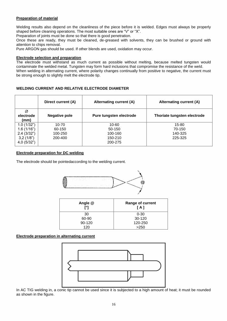
Preparation of material Welding results also depend on the cleanliness of the piece before it is welded. Edges must always be properly shaped before cleaning operations. The most suitable ones are “V” or “X”. Preparation of joints must be done so that there is good penetration. Once these are ready, they must be cleaned, de-greased with solvents, they can be brushed or ground with attention to chips removal. Pure ARGON gas should be used. If other blends are used, oxidation may occur. Electrode selection and preparation The electrode must withstand as much current as possible without melting, because melted tungsten would contaminate the welded metal. Tungsten may form hard inclusions that compromise the resistance of the weld. When welding in alternating current, where polarity changes continually from positive to negative, the current must be strong enough to slightly melt the electrode tip. WELDING CURRENT AND RELATIVE ELECTRODE DIAMETER
Direct current (A) Alternating current (A) Alternating current (A)
electrode
(mm)
Negative pole Pure tungsten electrode Thoriate tungsten electrode
1.0 (1/32”) 1.6 (1/16”) 2.4 (3/32”) 3,2 (1/8”) 4,0 (5/32”)
10-70 60-150 100-250 200-400
10-60 50-150 100-160 150-210 200-275
15-80 70-150 140-325 225-325
Electrode preparation for DC welding The electrode should be pointedaccording to the welding current.
Angle @ [°]
Range of current [ A ]
30 60-90
90-120 120
0-30 30-120 120-250
>250
Electrode preparation in alternating current
In AC TIG welding in, a conic tip cannot be used since it is subjected to a high amount of heat; it must be rounded as shown in the figure.

17
Shape of the electrode after AC TIG welding
Correct current output: The electrode tip is rounded by effect of slight melting. Excessive current: Excessive current has melted the electrode too much. There is the risk of tungsten inclusion in the welding bead. Use a larger diameter electrode. Insufficient Current: The arc is instable and particles of tungsten can be expelled. This is the result of an irregular tip surface. Use a smaller diameter electrode.
TYPES OF ELECTRODES
ELECTRODE COLOUR USE
Cerium-Tungsten Grey Universal
Pure Tungsten Green/Blue Aluminium and its alloys
Thorium Tungsten Red Fe-Stailess steel-Copper
Welding Position
Place the tip at 3-4 mm (.12 - .16in) from the weld piece, press the torch trigger, the arc will automatically ignite; as soon as the bath forms, move slowly and with constant speed so as to produce a bath that is uniform in penetration and width.
If filling material is used, keep the rod at a slope and about 20 mm (.79in) from the piece; when the weld pool becomes fluid, move the torch back and add material, touching the rod to the pool. (Filling material is always necessary for aluminium.)
Pull the rod away and position the torch back near the weld bead.
18
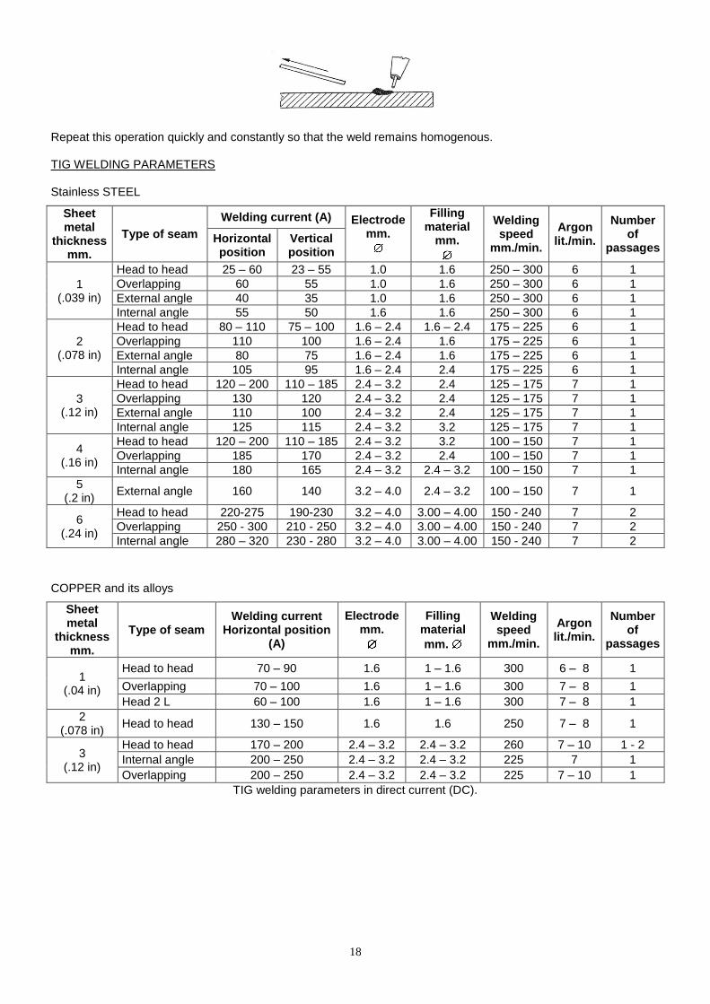
Repeat this operation quickly and constantly so that the weld remains homogenous. TIG WELDING PARAMETERS Stainless STEEL
Sheet metal
thickness mm.
Type of seam
Welding current (A) Electrode mm.
Filling material
mm.
Welding speed
mm./min.
Argon lit./min.
Number of
passages Horizontal position
Vertical position
1 (.039 in)
Head to head 25 – 60 23 – 55 1.0 1.6 250 – 300 6 1
Overlapping 60 55 1.0 1.6 250 – 300 6 1
External angle 40 35 1.0 1.6 250 – 300 6 1
Internal angle 55 50 1.6 1.6 250 – 300 6 1
2 (.078 in)
Head to head 80 – 110 75 – 100 1.6 – 2.4 1.6 – 2.4 175 – 225 6 1
Overlapping 110 100 1.6 – 2.4 1.6 175 – 225 6 1
External angle 80 75 1.6 – 2.4 1.6 175 – 225 6 1
Internal angle 105 95 1.6 – 2.4 2.4 175 – 225 6 1
3 (.12 in)
Head to head 120 – 200 110 – 185 2.4 – 3.2 2.4 125 – 175 7 1
Overlapping 130 120 2.4 – 3.2 2.4 125 – 175 7 1
External angle 110 100 2.4 – 3.2 2.4 125 – 175 7 1
Internal angle 125 115 2.4 – 3.2 3.2 125 – 175 7 1
4 (.16 in)
Head to head 120 – 200 110 – 185 2.4 – 3.2 3.2 100 – 150 7 1
Overlapping 185 170 2.4 – 3.2 2.4 100 – 150 7 1
Internal angle 180 165 2.4 – 3.2 2.4 – 3.2 100 – 150 7 1
5 (.2 in)
External angle 160 140 3.2 – 4.0 2.4 – 3.2 100 – 150 7 1
6 (.24 in)
Head to head 220-275 190-230 3.2 – 4.0 3.00 – 4.00 150 - 240 7 2
Overlapping 250 - 300 210 - 250 3.2 – 4.0 3.00 – 4.00 150 - 240 7 2
Internal angle 280 – 320 230 - 280 3.2 – 4.0 3.00 – 4.00 150 - 240 7 2
COPPER and its alloys
Sheet metal
thickness mm.
Type of seam Welding current
Horizontal position (A)
Electrode mm.
Filling material
mm.
Welding speed
mm./min.
Argon lit./min.
Number of
passages
1 (.04 in)
Head to head 70 – 90 1.6 1 – 1.6 300 6 – 8 1
Overlapping 70 – 100 1.6 1 – 1.6 300 7 – 8 1
Head 2 L 60 – 100 1.6 1 – 1.6 300 7 – 8 1
2 (.078 in)
Head to head 130 – 150 1.6 1.6 250 7 – 8 1
3 (.12 in)
Head to head 170 – 200 2.4 – 3.2 2.4 – 3.2 260 7 – 10 1 - 2
Internal angle 200 – 250 2.4 – 3.2 2.4 – 3.2 225 7 1
Overlapping 200 – 250 2.4 – 3.2 2.4 – 3.2 225 7 – 10 1
TIG welding parameters in direct current (DC).
19
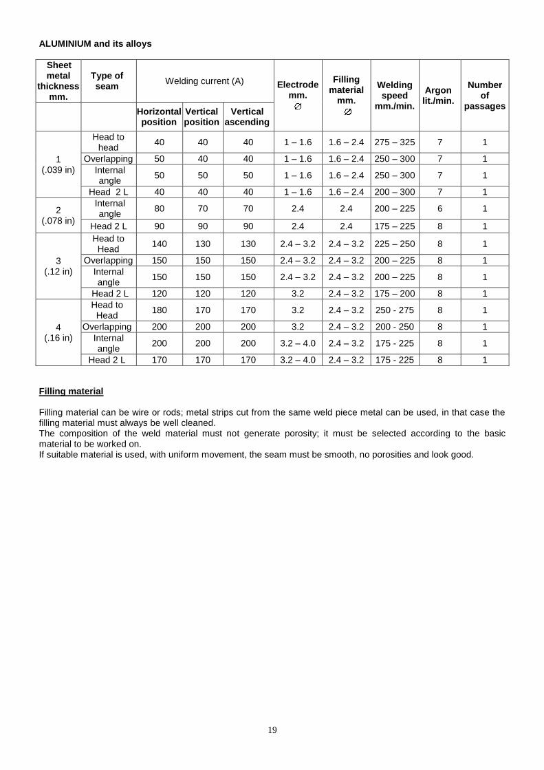
ALUMINIUM and its alloys
Sheet metal
thickness mm.
Type of seam
Welding current (A) Electrode mm.
Filling material
mm.
Welding speed
mm./min.
Argon lit./min.
Number of
passages
Horizontal position
Vertical position
Vertical ascending
1 (.039 in)
Head to head
40 40 40 1 – 1.6 1.6 – 2.4 275 – 325 7 1
Overlapping 50 40 40 1 – 1.6 1.6 – 2.4 250 – 300 7 1
Internal angle
50 50 50 1 – 1.6 1.6 – 2.4 250 – 300 7 1
Head 2 L 40 40 40 1 – 1.6 1.6 – 2.4 200 – 300 7 1
2 (.078 in)
Internal angle
80 70 70 2.4 2.4 200 – 225 6 1
Head 2 L 90 90 90 2.4 2.4 175 – 225 8 1
3 (.12 in)
Head to Head
140 130 130 2.4 – 3.2 2.4 – 3.2 225 – 250 8 1
Overlapping 150 150 150 2.4 – 3.2 2.4 – 3.2 200 – 225 8 1
Internal angle
150 150 150 2.4 – 3.2 2.4 – 3.2 200 – 225 8 1
Head 2 L 120 120 120 3.2 2.4 – 3.2 175 – 200 8 1
4 (.16 in)
Head to Head
180 170 170 3.2 2.4 – 3.2 250 - 275 8 1
Overlapping 200 200 200 3.2 2.4 – 3.2 200 - 250 8 1
Internal angle
200 200 200 3.2 – 4.0 2.4 – 3.2 175 - 225 8 1
Head 2 L 170 170 170 3.2 – 4.0 2.4 – 3.2 175 - 225 8 1
Filling material Filling material can be wire or rods; metal strips cut from the same weld piece metal can be used, in that case the filling material must always be well cleaned. The composition of the weld material must not generate porosity; it must be selected according to the basic material to be worked on. If suitable material is used, with uniform movement, the seam must be smooth, no porosities and look good.
20
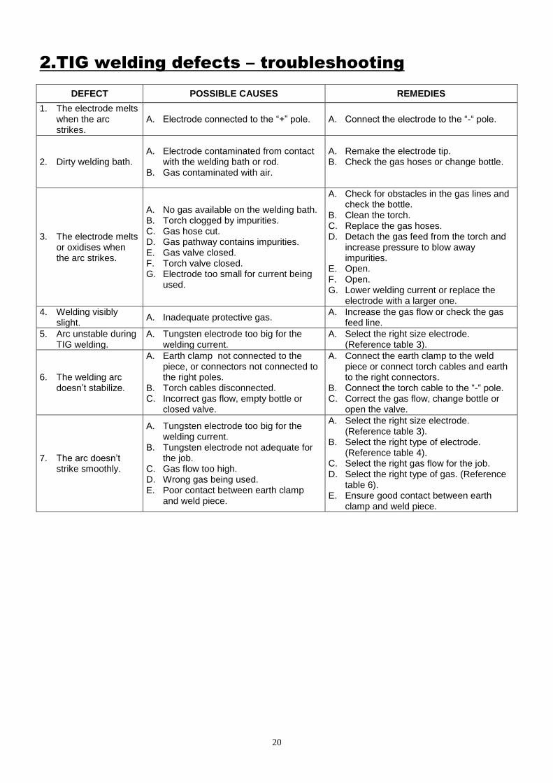
2.TIG welding defects – troubleshooting
DEFECT POSSIBLE CAUSES REMEDIES
1. The electrode melts when the arc strikes.
A. Electrode connected to the “+” pole. A. Connect the electrode to the “-“ pole.
2. Dirty welding bath. A. Electrode contaminated from contact
with the welding bath or rod. B. Gas contaminated with air.
A. Remake the electrode tip. B. Check the gas hoses or change bottle.
3. The electrode melts or oxidises when the arc strikes.
A. No gas available on the welding bath. B. Torch clogged by impurities. C. Gas hose cut. D. Gas pathway contains impurities. E. Gas valve closed. F. Torch valve closed. G. Electrode too small for current being
used.
A. Check for obstacles in the gas lines and check the bottle.
B. Clean the torch. C. Replace the gas hoses. D. Detach the gas feed from the torch and
increase pressure to blow away impurities.
E. Open. F. Open. G. Lower welding current or replace the
electrode with a larger one.
4. Welding visibly slight.
A. Inadequate protective gas. A. Increase the gas flow or check the gas
feed line.
5. Arc unstable during TIG welding.
A. Tungsten electrode too big for the welding current.
A. Select the right size electrode. (Reference table 3).
6. The welding arc doesn’t stabilize.
A. Earth clamp not connected to the piece, or connectors not connected to the right poles.
B. Torch cables disconnected. C. Incorrect gas flow, empty bottle or
closed valve.
A. Connect the earth clamp to the weld piece or connect torch cables and earth to the right connectors.
B. Connect the torch cable to the “-“ pole. C. Correct the gas flow, change bottle or
open the valve.
7. The arc doesn’t strike smoothly.
A. Tungsten electrode too big for the welding current.
B. Tungsten electrode not adequate for the job.
C. Gas flow too high. D. Wrong gas being used. E. Poor contact between earth clamp
and weld piece.
A. Select the right size electrode. (Reference table 3).
B. Select the right type of electrode. (Reference table 4).
C. Select the right gas flow for the job. D. Select the right type of gas. (Reference
table 6). E. Ensure good contact between earth
clamp and weld piece.

21
WHAT IF THE INVERTER DOESN’T WORK?
The welder doesn’t switch-on: check the mains connection and the switch position (1).
Irregular electrode welding: Check correct connection of the cable holder and earth clamp according to the electrode being used. Check that the welding current is appropriate for the electrode and the piece to be welded. Check that the electrodes are not wet or damaged. Check that the weld piece is not excessively dirty, greasy, etc. Check that the earth clamp is well connected to the weld piece.
The welder doesn’t generate the power required: Check that the mains voltage is between 210V-250V (even during welding) If extension cables are used, make sure that they conform to the table on page 9.
In TIG welding:
The torch spatters during welding: Check that the torch and earth are correctly connected. Check that gas is present and that the flow is sufficient. Check that the weld piece is not greasy or dirty. Check that the weld piece isn’t composed of alloys incompatible with the power source used. Check that the electrode is the right colour for the material to be welded. Check if too high a current setting is being used.
Duty Cycle too short: Check that the fan is turning. Check if the fan is blocked and that air circulates from the air grids. Check if the working environment is too hot.
22
AVAILABLE ACCESSORIES
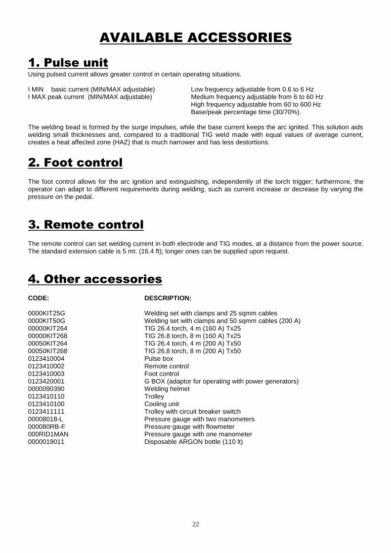
1. Pulse unit
Using pulsed current allows greater control in certain operating situations. I MIN basic current (MIN/MAX adjustable) Low frequency adjustable from 0.6 to 6 Hz I MAX peak current (MIN/MAX adjustable) Medium frequency adjustable from 6 to 60 Hz High frequency adjustable from 60 to 600 Hz
Base/peak percentage time (30/70%). The welding bead is formed by the surge impulses, while the base current keeps the arc ignited. This solution aids welding small thicknesses and, compared to a traditional TIG weld made with equal values of average current, creates a heat affected zone (HAZ) that is much narrower and has less destortions.
2. Foot control
The foot control allows for the arc ignition and extinguishing, independently of the torch trigger; furthermore, the operator can adapt to different requirements during welding, such as current increase or decrease by varying the pressure on the pedal.
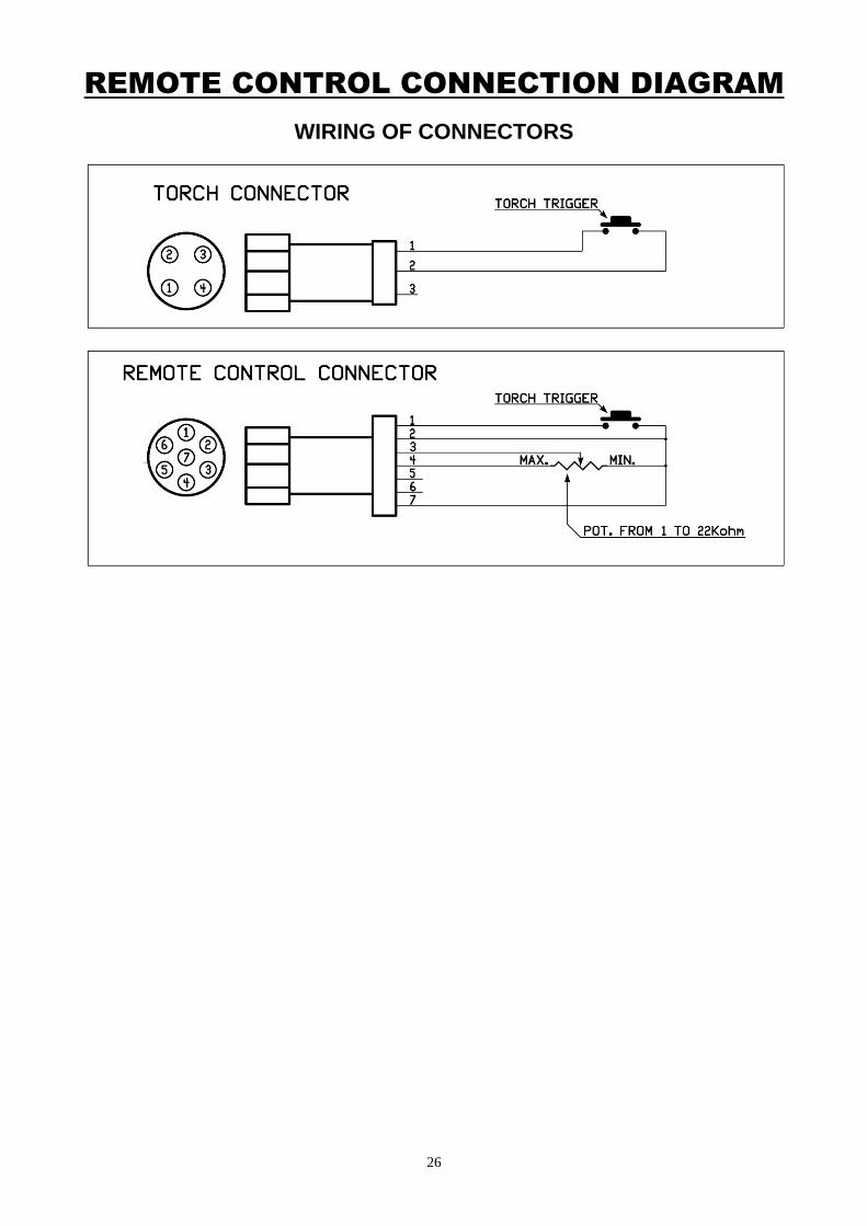
3. Remote control
The remote control can set welding current in both electrode and TIG modes, at a distance from the power source. The standard extension cable is 5 mt. (16.4 ft); longer ones can be supplied upon request.
4. Other accessories
CODE: DESCRIPTION: 0000KIT25G Welding set with clamps and 25 sqmm cables 0000KIT50G Welding set with clamps and 50 sqmm cables (200 A) 00000KIT264 TIG 26.4 torch, 4 m (160 A) Tx25 00000KIT268 TIG 26.8 torch, 8 m (160 A) Tx25 00050KIT264 TIG 26.4 torch, 4 m (200 A) Tx50 00050KIT268 TIG 26.8 torch, 8 m (200 A) Tx50 0123410004 Pulse box 0123410002 Remote control 0123410003 Foot control 0123420001 G BOX (adaptor for operating with power generators) 0000090390 Welding helmet 0123410110 Trolley 0123410100 Cooling unit 0123411111 Trolley with circuit breaker switch 00008018-L Pressure gauge with two manometers 000080RB-F Pressure gauge with flowmeter 000RID1MAN Pressure gauge with one manometer 0000019011 Disposable ARGON bottle (110 lt)
23
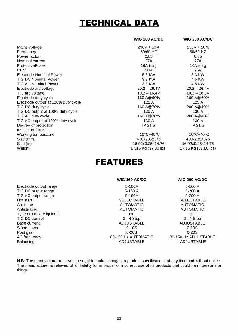
TECHNICAL DATA
WIG 160 AC/DC WIG 200 AC/DC
Mains voltage Frequency Power factor Nominal current ProtectiveFuses OCV Electrode Nominal Power TIG DC Nominal Power TIG AC Nominal Power Electrode arc voltage TIG arc voltage Electrode duty cycle Electrode output at 100% duty cycle TIG DC duty cycle TIG DC output at 100% duty cycle TIG AC duty cycle TIG AC output at 100% duty cycle Degree of protection Insulation Class Working temperature Size (mm) Size (in) Weight
230V + 10% 50/60 HZ
0,85 27A
16A t-lag 50V
5,3 KW 3,3 KW 3,3 KW
20,2 – 26,4V 10,2 – 16,4V 160 A@60%
125 A 160 A@70%
130 A 160 A@70%
130 A IP 21 S
F –10°C+40°C 430x235x375
16.92x9.25x14.76 17,15 Kg (37.80 lbs)
230V + 10% 50/60 HZ
0,85 27A
16A t-lag 95V
5,3 KW 4,5 KW 4,5 KW
20,2 – 26,4V 10,2 – 18,0V 160 A@60%
125 A 200 A@40%
130 A 200 A@40%
130 A IP 21 S
F –10°C+40°C 430x235x375
16.92x9.25x14.76 17,15 Kg (37.80 lbs)
FEATURES
WIG 160 AC/DC
WIG 200 AC/DC
Electrode output range TIG DC output range TIG AC output range Hot start Arc force Antisticking Type of TIG arc ignition TIG DC control Base current Slope down Post gas AC frequency Balancing
5-160A 5-160 A 5-160A
SELECTABLE AUTOMATIC AUTOMATIC
HF 2 - 4 Step
ADJUSTABLE 0-10S 0-20S
80-150 Hz AUTOMATIC ADJUSTABLE
5-160 A 5-200 A 5-200 A
SELECTABLE AUTOMATIC AUTOMATIC
HF 2 - 4 Step
ADJUSTABLE 0-10S 0-20S
80-150 Hz ADJUSTABLE ADJUSTABLE
N.B: The manufacturer reserves the right to make changes to product specifications at any time and without notice. The manufacturer is relieved of all liability for improper or incorrect use of its products that could harm persons or things.
24
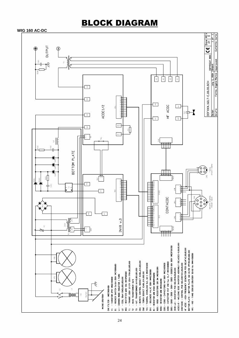
BLOCK DIAGRAM
WIG 160 AC-DC
25
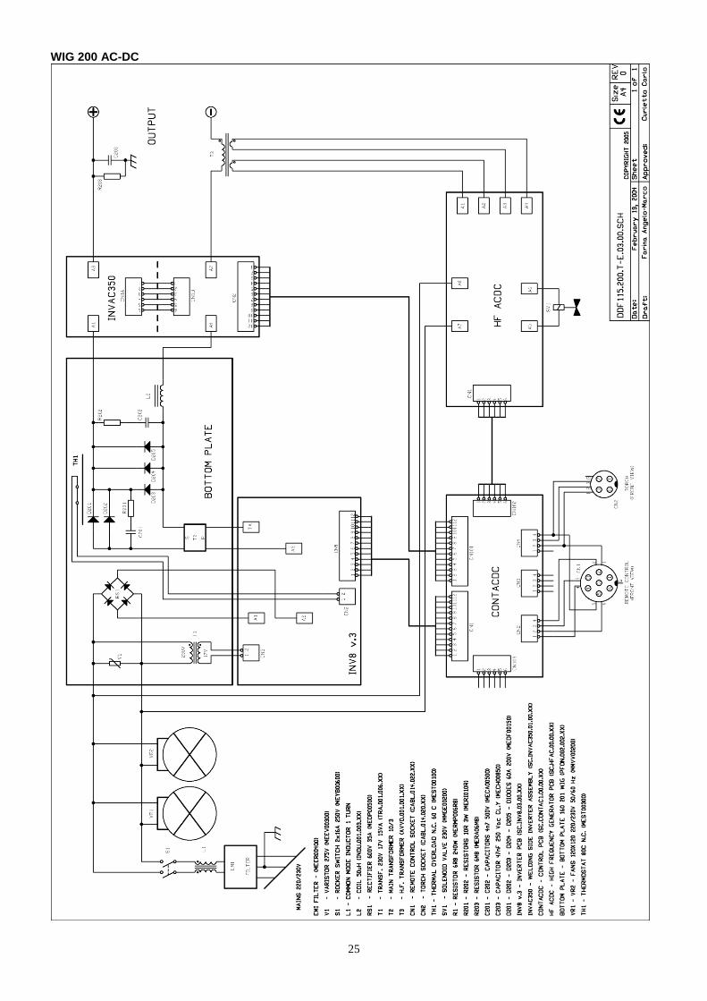
WIG 200 AC-DC
26
REMOTE CONTROL CONNECTION DIAGRAM
WIRING OF CONNECTORS
27
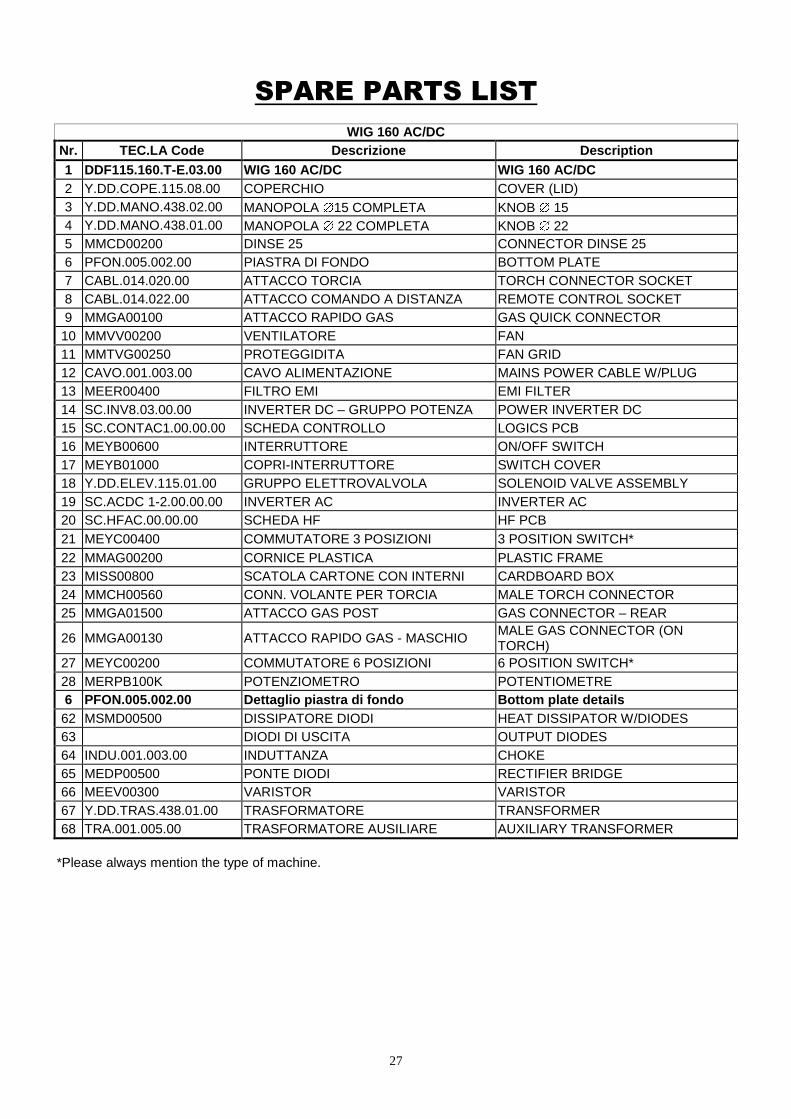
SPARE PARTS LIST
WIG 160 AC/DC
Nr. TEC.LA Code Descrizione Description
1 DDF115.160.T-E.03.00 WIG 160 AC/DC WIG 160 AC/DC
2 Y.DD.COPE.115.08.00 COPERCHIO COVER (LID)
3 Y.DD.MANO.438.02.00 MANOPOLA 15 COMPLETA KNOB 15
4 Y.DD.MANO.438.01.00 MANOPOLA 22 COMPLETA KNOB 22
5 MMCD00200 DINSE 25 CONNECTOR DINSE 25
6 PFON.005.002.00 PIASTRA DI FONDO BOTTOM PLATE
7 CABL.014.020.00 ATTACCO TORCIA TORCH CONNECTOR SOCKET
8 CABL.014.022.00 ATTACCO COMANDO A DISTANZA REMOTE CONTROL SOCKET
9 MMGA00100 ATTACCO RAPIDO GAS GAS QUICK CONNECTOR
10 MMVV00200 VENTILATORE FAN
11 MMTVG00250 PROTEGGIDITA FAN GRID
12 CAVO.001.003.00 CAVO ALIMENTAZIONE MAINS POWER CABLE W/PLUG
13 MEER00400 FILTRO EMI EMI FILTER
14 SC.INV8.03.00.00 INVERTER DC – GRUPPO POTENZA POWER INVERTER DC
15 SC.CONTAC1.00.00.00 SCHEDA CONTROLLO LOGICS PCB
16 MEYB00600 INTERRUTTORE ON/OFF SWITCH
17 MEYB01000 COPRI-INTERRUTTORE SWITCH COVER
18 Y.DD.ELEV.115.01.00 GRUPPO ELETTROVALVOLA SOLENOID VALVE ASSEMBLY
19 SC.ACDC 1-2.00.00.00 INVERTER AC INVERTER AC
20 SC.HFAC.00.00.00 SCHEDA HF HF PCB
21 MEYC00400 COMMUTATORE 3 POSIZIONI 3 POSITION SWITCH*
22 MMAG00200 CORNICE PLASTICA PLASTIC FRAME
23 MISS00800 SCATOLA CARTONE CON INTERNI CARDBOARD BOX
24 MMCH00560 CONN. VOLANTE PER TORCIA MALE TORCH CONNECTOR
25 MMGA01500 ATTACCO GAS POST GAS CONNECTOR – REAR
26 MMGA00130 ATTACCO RAPIDO GAS - MASCHIO MALE GAS CONNECTOR (ON TORCH)
27 MEYC00200 COMMUTATORE 6 POSIZIONI 6 POSITION SWITCH*
28 MERPB100K POTENZIOMETRO POTENTIOMETRE
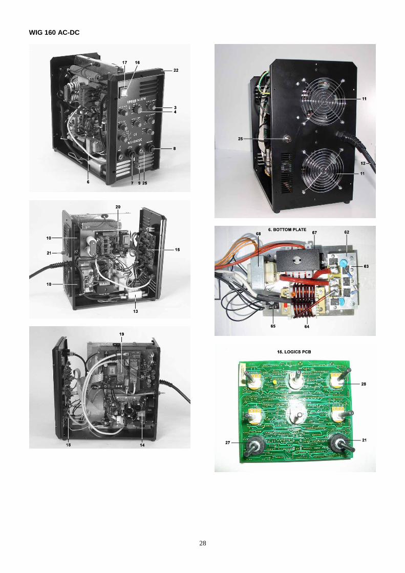
6 PFON.005.002.00 Dettaglio piastra di fondo Bottom plate details
62 MSMD00500 DISSIPATORE DIODI HEAT DISSIPATOR W/DIODES
63 DIODI DI USCITA OUTPUT DIODES
64 INDU.001.003.00 INDUTTANZA CHOKE
65 MEDP00500 PONTE DIODI RECTIFIER BRIDGE
66 MEEV00300 VARISTOR VARISTOR
67 Y.DD.TRAS.438.01.00 TRASFORMATORE TRANSFORMER
68 TRA.001.005.00 TRASFORMATORE AUSILIARE AUXILIARY TRANSFORMER
*Please always mention the type of machine.
28
WIG 160 AC-DC
29
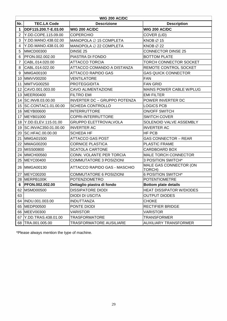
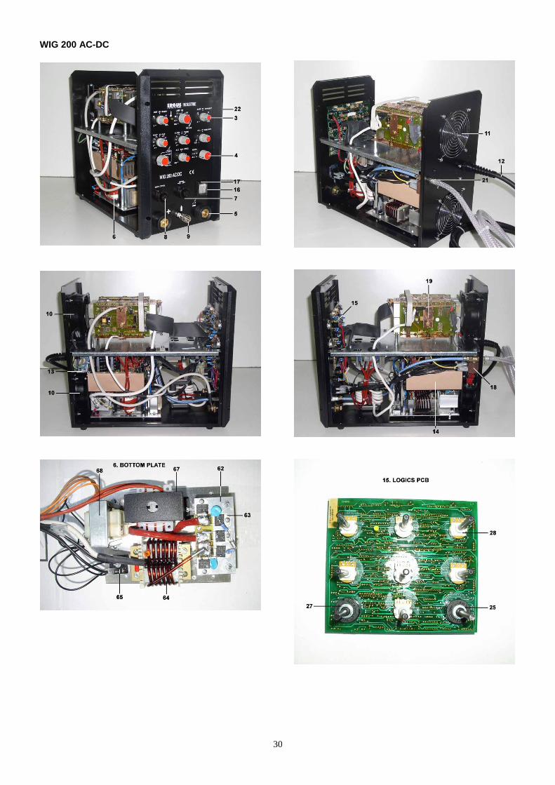
WIG 200 AC/DC
Nr. TEC.LA Code Descrizione Description
1 DDF115.200.T-E.03.00 WIG 200 AC/DC WIG 200 AC/DC
2 Y.DD.COPE.115.09.00 COPERCHIO COVER (LID)
3 Y.DD.MANO.438.02.00 MANOPOLA 15 COMPLETA KNOB 15
4 Y.DD.MANO.438.01.00 MANOPOLA 22 COMPLETA KNOB 22
5 MMCD00300 DINSE 25 CONNECTOR DINSE 25
6 PFON.002.002.00 PIASTRA DI FONDO BOTTOM PLATE
7 CABL.014.020.00 ATTACCO TORCIA TORCH CONNECTOR SOCKET
8 CABL.014.022.00 ATTACCO COMANDO A DISTANZA REMOTE CONTROL SOCKET
9 MMGA00100 ATTACCO RAPIDO GAS GAS QUICK CONNECTOR
10 MMVV00200 VENTILATORE FAN
11 MMTVG00250 PROTEGGIDITA FAN GRID
12 CAVO.001.003.00 CAVO ALIMENTAZIONE MAINS POWER CABLE W/PLUG
13 MEER00400 FILTRO EMI EMI FILTER
14 SC.INV8.03.00.00 INVERTER DC – GRUPPO POTENZA POWER INVERTER DC
15 SC.CONTAC1.01.00.00 SCHEDA CONTROLLO LOGICS PCB
16 MEYB00600 INTERRUTTORE ON/OFF SWITCH
17 MEYB01000 COPRI-INTERRUTTORE SWITCH COVER
18 Y.DD.ELEV.115.01.00 GRUPPO ELETTROVALVOLA SOLENOID VALVE ASSEMBLY
19 SC.INVAC350.01.00.00 INVERTER AC INVERTER AC
20 SC.HFAC.00.00.00 SCHEDA HF HF PCB
21 MMGA01500 ATTACCO GAS POST GAS CONNECTOR – REAR
22 MMAG00200 CORNICE PLASTICA PLASTIC FRAME
23 MISS00800 SCATOLA CARTONE CARDBOARD BOX
24 MMCH00560 CONN. VOLANTE PER TORCIA MALE TORCH CONNECTOR
25 MEYC00400 COMMUTATORE 3 POSIZIONI 3 POSITION SWITCH*
26 MMGA00130 ATTACCO RAPIDO GAS - MASCHIO MALE GAS CONNECTOR (ON TORCH)
27 MEYC00200 COMMUTATORE 6 POSIZIONI 6 POSITION SWITCH*
28 MERPB100K POTENZIOMETRO POTENTIOMETRE
6 PFON.002.002.00 Dettaglio piastra di fondo Bottom plate details
62 MSMD00500 DISSIPATORE DIODI HEAT DISSIPATOR W/DIODES
63 DIODI DI USCITA OUTPUT DIODES
64 INDU.001.003.00 INDUTTANZA CHOKE
65 MEDP00500 PONTE DIODI RECTIFIER BRIDGE
66 MEEV00300 VARISTOR VARISTOR
67 Y.DD.TRAS.438.01.00 TRASFORMATORE TRANSFORMER
68 TRA.001.005.00 TRASFORMATORE AUSILIARE AUXILIARY TRANSFORMER
*Please always mention the type of machine.
30
WIG 200 AC-DC

31
TEC.LA. S.r.l. Via Castel Morrone 15/C - 16161 Genova – ITALIA
Phone: +39 0107 450 222 – 0107 411 034 Fax +39 0107 406 917
e-mail [email protected]