implement guide
TRANSCRIPT
SuperStack® 3Switch 3226 and Switch 3250Implementation Guide
http://www.3com.com/
Part No. DUA1750-0BAA01Published December 2003
3CR17500-913CR17501-91
3Com Corporation350 Campus DriveMarlborough, MAUSA 01752-3064
Copyright © 2003, 3Com Corporation. All rights reserved. No part of this documentation may be reproduced in any form or by any means or used to make any derivative work (such as translation, transformation, or adaptation) without written permission from 3Com Corporation.
3Com Corporation reserves the right to revise this documentation and to make changes in content from time to time without obligation on the part of 3Com Corporation to provide notification of such revision or change.
3Com Corporation provides this documentation without warranty, term, or condition of any kind, either implied or expressed, including, but not limited to, the implied warranties, terms or conditions of merchantability, satisfactory quality, and fitness for a particular purpose. 3Com may make improvements or changes in the product(s) and/or the program(s) described in this documentation at any time.
If there is any software on removable media described in this documentation, it is furnished under a license agreement included with the product as a separate document, in the hard copy documentation, or on the removable media in a directory file named LICENSE.TXT or !LICENSE.TXT. If you are unable to locate a copy, please contact 3Com and a copy will be provided to you.
UNITED STATES GOVERNMENT LEGEND
If you are a United States government agency, then this documentation and the software described herein are provided to you subject to the following:
All technical data and computer software are commercial in nature and developed solely at private expense. Software is delivered as “Commercial Computer Software” as defined in DFARS 252.227-7014 (June 1995) or as a “commercial item” as defined in FAR 2.101(a) and as such is provided with only such rights as are provided in 3Com’s standard commercial license for the Software. Technical data is provided with limited rights only as provided in DFAR 252.227-7015 (Nov 1995) or FAR 52.227-14 (June 1987), whichever is applicable. You agree not to remove or deface any portion of any legend provided on any licensed program or documentation contained in, or delivered to you in conjunction with, this User Guide.
Unless otherwise indicated, 3Com registered trademarks are registered in the United States and may or may not be registered in other countries.
3Com, SuperStack, and the 3Com logo are registered trademarks of 3Com Corporation.
Intel and Pentium are registered trademarks of Intel Corporation. Microsoft, MS-DOS, Windows, and Windows NT are registered trademarks of Microsoft Corporation. Novell and NetWare are registered trademarks of Novell, Inc. UNIX is a registered trademark in the United States and other countries, licensed exclusively through X/Open Company, Ltd. Solaris is a registered trademark of Sun Microsystems.
IEEE and 802 are registered trademarks of the Institute of Electrical and Electronics Engineers, Inc.
All other company and product names may be trademarks of the respective companies with which they are associated.
ENVIRONMENTAL STATEMENT
It is the policy of 3Com Corporation to be environmentally-friendly in all operations. To uphold our policy, we are committed to:
Establishing environmental performance standards that comply with national legislation and regulations.
Conserving energy, materials and natural resources in all operations.
Reducing the waste generated by all operations. Ensuring that all waste conforms to recognized environmental standards. Maximizing the recyclable and reusable content of all products.
Ensuring that all products can be recycled, reused and disposed of safely.
Ensuring that all products are labelled according to recognized environmental standards.
Improving our environmental record on a continual basis.
End of Life Statement
3Com processes allow for the recovery, reclamation and safe disposal of all end-of-life electronic components.
Regulated Materials Statement
3Com products do not contain any hazardous or ozone-depleting material.
Environmental Statement about the Documentation
The documentation for this product is printed on paper that comes from sustainable, managed forests; it is fully biodegradable and recyclable, and is completely chlorine-free. The varnish is environmentally-friendly, and the inks are vegetable-based with a low heavy-metal content.
ENCRYPTION
This product contains encryption and may require U.S. and/or local government authorization prior to export or import to another country.
CONTENTS
ABOUT THIS GUIDE
Conventions 10Related Documentation 11Documentation Comments 11
1 SWITCH FEATURES OVERVIEW
What is Management Software? 13Switch Features Explained 13
Aggregated Links 14Auto-negotiation 14Configuration Save and Restore 15Multicast Filtering 16Rapid Spanning Tree Protocol 16Switch Database 17Traffic Prioritization 17Rate Limiting 17RMON 17Broadcast Storm Control 18VLANs 18Automatic IP Configuration 18Port Security 18IP Routing 19Dynamic Routing 19
2 OPTIMIZING BANDWIDTH
Port Features 21Duplex 21Flow Control 22Auto-negotiation 22
Aggregated Links 23How 802.3ad Link Aggregation Operates 23
Implementing 802.3ad Aggregated Links 25Aggregated Links and Your Switch 25Aggregated Link — Manual Configuration Example 27
3 USING MULTICAST FILTERING
What is an IP Multicast? 29Benefits of Multicast 30
Multicast Filtering 30Multicast Filtering and Your Switch 31
IGMP Multicast Filtering 31How IGMP Supports IP Multicast 32Role of IGMP in IP Multicast Filtering 34
4 USING RESILIENCE FEATURES
Rapid Spanning Tree Protocol 35Rapid Spanning Tree Protocol (RSTP) 36
What is STP? 36How STP Works 38
STP Requirements 38STP Calculation 39STP Configuration 39STP Reconfiguration 40How RSTP Differs to STP 40STP Example 40STP Configurations 42
Using STP on a Network with Multiple VLANs 44
5 USING THE SWITCH DATABASE
What is the Switch Database? 45How Switch Database Entries Get Added 45Switch Database Entry States 46
6 USING TRAFFIC MANAGEMENT
What is Traffic Prioritization? 47How Traffic Prioritization Works 48
802.1D traffic classification 48DiffServ traffic classification 49IP Port traffic classification 50
Traffic Prioritization and your Switch 51Limiting the Rate of a Port 52
Traffic Prioritization and Rate Limiting 53
7 STATUS MONITORING AND STATISTICS
RMON 55What is RMON? 55
The RMON Groups 55Benefits of RMON 57RMON and the Switch 57
Alarm Events 58
8 SETTING UP VIRTUAL LANS
What are VLANs? 59Benefits of VLANs 60VLANs and Your Switch 61
The Default VLAN 61Communication Between VLANs 61Creating New VLANs 63VLANs: Tagged and Untagged Membership 63
VLAN Configuration Examples 64Using Untagged Connections 64Using 802.1Q Tagged Connections 65
9 USING AUTOMATIC IP CONFIGURATION
How Your Switch Obtains IP Information 67How Automatic IP Configuration Works 68
Automatic Process 68Important Considerations 68
Server Support 68
10 MAKING YOUR NETWORK SECURE
Limiting Management Access by IP Address 71Securing Access to the Web Interface 72
Getting a Digital Certificate 72Securing Access to the Command Line Interface 73Access Control Lists 73
How Access Control List Rules Work 74Port Security 74What is Network Login? 75
How Network Login Works 75Important Considerations 76
What is Switch Management Login? 77Benefits of RADIUS Authentication 77How RADIUS Authentication Works 78Important Considerations 79
What is RADIUS? 80
11 IP ROUTING
What is Routing? 82Routing in a Subnetworked Environment 82
What is IP Routing? 83Benefits of IP Routing 84IP Routing Concepts 84
Router Interfaces 84Routing Tables 85Layer 3 Switching 86
Multiple IP Interfaces per VLAN 87Implementing IP Routing 88
Configuring IP VLANs 88Establishing IP Interfaces 88
IP Routing Protocols 90Routing Information Protocol (RIP) 90User Datagram Protocol (UDP) Helper 93Address Resolution Protocol (ARP) 94ARP Proxy 96Internet Control Message Protocol (ICMP) 97
Advanced IP Routing Options 97
A CONFIGURATION RULES
Configuration Rules for Gigabit Ethernet 99Configuration Rules for Fast Ethernet 100
Configuration Rules with Full Duplex 101
B NETWORK CONFIGURATION EXAMPLES
Simple Network Configuration Example 104Desktop Switch Example 104
Advanced Network Configuration Example 105Edge Switch Example 105
C IP ADDRESSING
IP Addresses 107Simple Overview 107Advanced Overview 108
Subnets and Subnet Masks 110Default Gateways 112
D ADVANCED IP ROUTING CONCEPTS
Variable Length Subnet Masks (VLSMs) 113Supernetting 114
GLOSSARY
INDEX

ABOUT THIS GUIDE
This guide describes the features of the 3Com® SuperStack® 3 Switch 3226 (3CR17500-91) and 3Com® SuperStack® 3 Switch 3250 (3CR17501-91). It outlines how to use these features to optimize the performance of your network.
The terms Switch 3226 and Switch 3250 are used when referring to the 3Com SuperStack 3 Switch 3226 and 3Com SuperStack 3 Switch 3250. The term Switch is used when referring to information that applies to both Switches.
Refer to the Management Quick Reference Guide that accompanies your Switch for details of the specific features your Switch supports.
This guide is intended for the system or network administrator who is responsible for configuring, using, and managing the Switches. It assumes a working knowledge of local area network (LAN) operations and familiarity with communication protocols that are used to interconnect LANs.
For detailed descriptions of the Web interface operations and the Command Line Interface (CLI) commands that you require to manage the Switch please refer to the Management Interface Reference Guide supplied in HTML format on the CD-ROM that accompanies your Switch or on the 3Com Web site.
If release notes are shipped with your product and the information there differs from the information in this guide, follow the instructions in the release notes.
Most user guides and release notes are available in Adobe Acrobat Reader Portable Document Format (PDF) or HTML on the 3Com World Wide Web site:
http://www.3com.com/
10 ABOUT THIS GUIDE
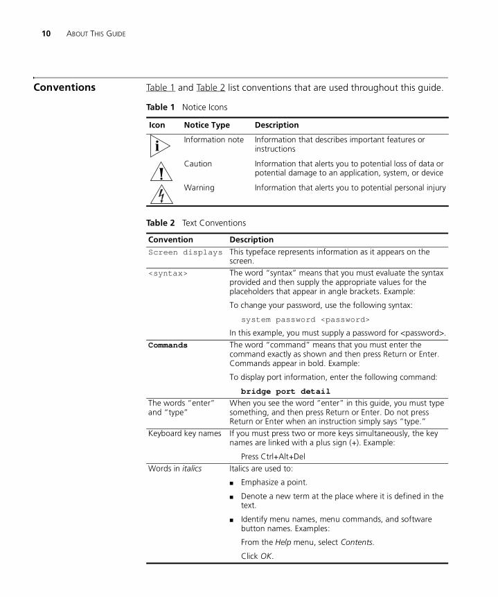
Conventions Table 1 and Table 2 list conventions that are used throughout this guide.
Table 1 Notice Icons
Icon Notice Type Description
Information note Information that describes important features or instructions
Caution Information that alerts you to potential loss of data or potential damage to an application, system, or device
Warning Information that alerts you to potential personal injury
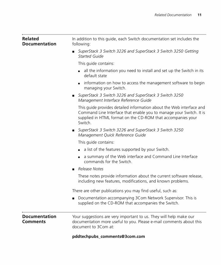
Table 2 Text Conventions
Convention Description
Screen displays This typeface represents information as it appears on the screen.
<syntax> The word “syntax” means that you must evaluate the syntax provided and then supply the appropriate values for the placeholders that appear in angle brackets. Example:
To change your password, use the following syntax:
system password <password>
In this example, you must supply a password for <password>.
Commands The word “command” means that you must enter the command exactly as shown and then press Return or Enter. Commands appear in bold. Example:
To display port information, enter the following command:
bridge port detail
The words “enter” and “type”
When you see the word “enter” in this guide, you must type something, and then press Return or Enter. Do not press Return or Enter when an instruction simply says “type.”
Keyboard key names If you must press two or more keys simultaneously, the key names are linked with a plus sign (+). Example:
Press Ctrl+Alt+Del
Words in italics Italics are used to:
■ Emphasize a point.
■ Denote a new term at the place where it is defined in the text.
■ Identify menu names, menu commands, and software button names. Examples:
From the Help menu, select Contents.
Click OK.
Related Documentation 11
Related Documentation
In addition to this guide, each Switch documentation set includes the following:
■ SuperStack 3 Switch 3226 and SuperStack 3 Switch 3250 Getting Started Guide
This guide contains:
■ all the information you need to install and set up the Switch in its default state
■ information on how to access the management software to begin managing your Switch.
■ SuperStack 3 Switch 3226 and SuperStack 3 Switch 3250 Management Interface Reference Guide
This guide provides detailed information about the Web interface and Command Line Interface that enable you to manage your Switch. It is supplied in HTML format on the CD-ROM that accompanies your Switch.
■ SuperStack 3 Switch 3226 and SuperStack 3 Switch 3250 Management Quick Reference Guide
This guide contains:
■ a list of the features supported by your Switch.
■ a summary of the Web interface and Command Line Interface commands for the Switch.
■ Release Notes
These notes provide information about the current software release, including new features, modifications, and known problems.
There are other publications you may find useful, such as:
■ Documentation accompanying 3Com Network Supervisor. This is supplied on the CD-ROM that accompanies the Switch.
Documentation Comments
Your suggestions are very important to us. They will help make our documentation more useful to you. Please e-mail comments about this document to 3Com at:
12 ABOUT THIS GUIDE
Please include the following information when contacting us:
■ Document title
■ Document part number (on the title page)
■ Page number (if appropriate)
Example:
■ SuperStack® 3 Switch 3226 and Switch 3250 Implementation Guide
■ Part number: DUA1750-0BAA01
■ Page 25
Please note that we can only respond to comments and questions about 3Com product documentation at this e-mail address. Questions related to technical support or sales should be directed in the first instance to your network supplier.
1
SWITCH FEATURES OVERVIEWThis chapter contains introductory information about the Switch management software and supported features. It covers the following topics:
■ What is Management Software?
■ Switch Features Explained
For detailed descriptions of the Web interface operations and the Command Line Interface (CLI) commands that you require to manage the Switch please refer to the Management Interface Reference Guide supplied in HTML format on the CD-ROM that accompanies your Switch.
What is Management Software?
Your Switch can operate in its default state. However, to make full use of the features offered by the Switch, and to change and monitor the way it works, you have to access the management software that resides on the Switch. This is known as managing the Switch.
Managing the Switch can help you to improve its efficiency and therefore the overall performance of your network.
There are several different methods of accessing the management software to manage the Switch. These methods are explained in Chapter 3 of the Getting Started Guide that accompanies your Switch.
Switch Features Explained
The management software provides you with the capability to change the default state of some of the Switch features. This section provides a brief overview of these features — their applications are explained in more detail later in this guide.
For a list of the features supported by your Switch, please refer to the Management Quick Reference Guide that accompanies your Switch.
14 CHAPTER 1: SWITCH FEATURES OVERVIEW
Aggregated Links Aggregated links are connections that allow devices to communicate using multiple links in parallel. Your Switch supports one aggregated link using the two 10/100/1000 and SFP ports (25-26 on the Switch 3225, 49-50 on the Switch 3250). Aggregated links provide two benefits:
■ They can potentially increase the bandwidth of a connection.
■ They can provide redundancy — if one link is broken, the other link will still pass traffic.
The Switch implements the IEEE 802.3ad standard for link aggregation.
For more information about aggregated links, see Chapter 2 “Optimizing Bandwidth”.
Auto-negotiation Auto-negotiation allows ports to auto-negotiate port speed, duplex-mode (only at 10 Mbps and 100 Mbps) and flow control. When auto-negotiation is enabled (default), a port “advertises” its maximum capabilities — these capabilities are by default the parameters that provide the highest performance supported by the port.
SFP ports do not support auto-negotiation of port speed.
Ports operating at 1000 Mbps only support full duplex mode.
For details of the auto-negotiation features supported by your Switch, please refer to the Management Quick Reference Guide that accompanies your Switch.
Auto MDI/MDI-X
Auto MDI/MDI-X allows ports to detect whether they are connected to a computer or another switch and configure themselves accordingly. This eliminates the need for crossover cables.
Duplex
Full duplex mode allows packets to be transmitted and received simultaneously and, in effect, doubles the potential throughput of a link.
Flow Control
All Switch ports support flow control, which is a mechanism that minimizes packet loss during periods of congestion on the network.
Switch Features Explained 15
Flow control uses backjamming on ports operating in half duplex mode, and is implemented using the IEEE Std 802.3-2002 (incorporating 802.3x) on ports operating in full duplex mode.
For more information about auto-negotiation and port capabilities, see Chapter 2 “Optimizing Bandwidth”.
Configuration Saveand Restore
The Configuration Save and Restore feature allows the configuration of your Switch to be saved as a file on a remote server, or to be restored onto the Switch from a file on a remote server. The configuration information is stored in an ASCII text file.
All configuration information that can be set using the Switch’s Command Line Interface is saved and restored.
Security information such as passwords and management IP information will not be saved in the configuration file.
You must have read/write management access level to be able to save and restore the Switch configuration.
Important Considerations
■ 3Com recommends the Switch unit is reset to its factory default settings before you restore a configuration onto it. You can reset the Switch using the system control initialize CLI command or the System > Control > Initialize Web interface operation.
■ The configuration can only be restored onto a device which has the same physical connections as when the configuration was initially saved. The restore operation will be unsuccessful if the physical configuration of the device is different.
■ The configuration of the Switch must only be restored or saved by a single user at a time.
■ When using the Configuration Save and Restore feature, 3Com recommends that aggregated links are configured as either:
■ Manual aggregations with Link Aggregation Configuration Protocol (LACP) disabled on the ports that are to be manually placed in the aggregated link.
or
16 CHAPTER 1: SWITCH FEATURES OVERVIEW
■ LACP automatic aggregations — that is, LACP enabled on all ports and the aggregated links created automatically. The aggregated link should be enabled and Spanning Tree Protocol enabled.
Parameters such as VLANs and Fast Start may be set up as required.
For further information about LACP, see Chapter 2 “Optimizing Bandwidth”.
■ When restoring a configuration onto a unit over an aggregated link, communication with that unit may be lost because the restore operation disables the aggregated link ports. Communication over the aggregated links is re-established when the restore operation has been completed.
For detailed descriptions of the Configuration Save and Restore Web interface operations and Command Line Interface (CLI) commands, please refer to the Management Interface Reference Guide supplied in HTML format on the CD-ROM that accompanies your Switch.
Multicast Filtering Multicast filtering allows the Switch to forward multicast traffic to only the endstations that are part of a predefined multicast group, rather than broadcasting the traffic to the whole network.
The multicast filtering system supported by your Switch uses IGMP (Internet Group Management Protocol) snooping to detect the endstations in each multicast group to which multicast traffic should be forwarded.
For more information about multicast filtering, see Chapter 3 “Using Multicast Filtering”.
Rapid Spanning TreeProtocol
Rapid Spanning Tree Protocol (RSTP) is a bridge-based systems that makes your network more resilient to link failure and also provides protection from network loops — one of the major causes of broadcast storms.
RSTP allows you to implement alternative paths for network traffic in the event of path failure and uses a loop-detection process to:
■ Discover the efficiency of each path.
■ Enable the most efficient path.
■ Disable the less efficient paths.
Switch Features Explained 17
■ Enable one of the less efficient paths if the most efficient path fails.
RSTP is an enhanced version of STP (Spanning Tree Protocol) and is fully compatible with STP systems. RSTP can restore a network connection quicker than the legacy STP feature. RSTP can detect if it is connected to a legacy device that only supports IEEE 802.1D STP and will automatically downgrade to STP on that particular port.
RSTP conforms to the IEEE Std 802.1w-2001.
For more information about RSTP, see Chapter 4 “Using Resilience Features”.
Switch Database The Switch Database is an integral part of the Switch and is used by the Switch to determine if a packet should be forwarded, and which port should transmit the packet if it is to be forwarded.
For more information about the Switch Database, see Chapter 5 “Using the Switch Database”.
Traffic Prioritization The traffic prioritization capabilities of your Switch provides Class of Service (CoS) prioritization to your network. You can prioritize traffic on your network to ensure that high priority data is transmitted with minimum delay.
For more information about traffic prioritization, see Chapter 6 “Using Traffic Management”.
Rate Limiting Rate limiting is the restriction of the bandwidth to or from a section of your network. Limiting the rate of network traffic reduces the stress on your network and, when used with traffic prioritization, ensures that important traffic is not held up when the network is busy.
For more information about rate limiting, see Chapter 6 “Using Traffic Management”.
RMON Remote Monitoring (RMON) is an industry standard feature for traffic monitoring and collecting network statistics. The Switch software continually collects statistics about the LAN segments connected to the Switch. If you have a management workstation with an RMON
18 CHAPTER 1: SWITCH FEATURES OVERVIEW
management application, the Switch can transfer these statistics to your workstation on request or when a pre-defined threshold is exceeded.
For more information about RMON and Event Notification, see Chapter 7 “Status Monitoring and Statistics”.
Broadcast StormControl
Broadcast Storm Control is a system that monitors the level of broadcast traffic on that port. If the broadcast traffic level rises to a pre-defined number of frames per second (threshold), the broadcast traffic on the port is blocked until the broadcast traffic level drops below the threshold. This system prevents the overwhelming broadcast traffic that can result from network equipment which is faulty or configured incorrectly.
VLANs A Virtual LAN (VLAN) is a flexible group of devices that can be located anywhere in a network, but which communicate as if they are on the same physical segment. With VLANs, you can segment your network without being restricted by physical connections — a limitation of traditional network design. As an example, with VLANs you can segment your network according to:
■ Departmental groups
■ Hierarchical groups
■ Usage groups
For more information about VLANs, see Chapter 8 “Setting Up Virtual LANs”.
Automatic IPConfiguration
Your Switch can have its IP information automatically configured using a DHCP server. Alternatively, you can manually configure the IP information.
For more information about how the automatic IP configuration feature works, see Chapter 9 “Using Automatic IP Configuration”.
Port Security Your Switch supports the following port security modes, which you can set for an individual port or a range of ports:
■ No Security
Port security is disabled and all network traffic is forwarded through the port without any restrictions.
■ Secure
Switch Features Explained 19
All currently learnt addresses on the port are made permanent. Any packets containing a source address not learnt on the port will be dropped.
■ Network Login
Connections are only allowed on a port once the client has been authenticated by a RADIUS server.
For more information about how Port Security works, see Chapter 10 “Making Your Network Secure”.
IP Routing IP Routing is a method for distributing traffic throughout an IP network. It is used to join LANs at the network layer, that is Layer 3 of the OSI (Open Systems Interconnection) model. Your Switch is optimized for Layer 3 edge configurations and has only limited functionality as a core switch.
Dynamic Routing Dynamic routing allows the Switch to adjust automatically to changes in network topology or traffic.
Routing Information Protocol (RIP)
RIP is a dynamic routing protocol that allows the Switch to adjust automatically to changes in network topology or traffic. Routes are calculated between networks automatically.
For more information about Layer 3 Routing, see Chapter 11 “IP Routing”

20 CHAPTER 1: SWITCH FEATURES OVERVIEW
2
OPTIMIZING BANDWIDTHThere are many ways you can optimize the bandwidth on your network and improve network performance. If you utilize certain Switch features you can provide the following benefits to your network and end users:
■ Increased bandwidth
■ Quicker connections
■ Faster transfer of data
■ Minimized data errors
■ Reduced network downtime
For detailed descriptions of the Web interface operations and the Command Line Interface (CLI) commands that you require to manage the Switch please refer to the Management Interface Reference Guide supplied in HTML format on the CD-ROM that accompanies your Switch.
Port Features The default state for all the features detailed below provides the best configuration for most users. In normal operation, you do not need to alter the Switch from its default state. However, under certain conditions you may wish to alter the default state of these ports, for example, if you are connecting to old equipment that does not comply with the IEEE 802.3x standard.
Duplex Full duplex allows packets to be transmitted and received simultaneously and, in effect, doubles the potential throughput of a link. Half duplex only allows packets to be transmitted or received at any one time.
To communicate effectively, both devices at either end of a link must use the same duplex mode. If the devices at either end of a link support auto-negotiation, this is done automatically. If the devices at either end of
22 CHAPTER 2: OPTIMIZING BANDWIDTH
a link do not support auto-negotiation, both ends must be manually set to full duplex or half duplex accordingly.
Ports operating at 1000 Mbps support full duplex mode only.
Flow Control All Switch ports support flow control, which is a mechanism that prevents packet loss during periods of congestion on the network. Packet loss is caused by one or more devices sending traffic to an already overloaded port on the Switch. Flow control prevents packet loss by inhibiting the transmitting port from generating more packets until the period of congestion ends.
Flow control is implemented using the IEEE Std 802.3-2002 (incorporating 802.3x) for ports operating in full duplex mode, and Intelligent Flow Management (IFM) for ports operating in half duplex mode.
Auto-negotiation Auto-negotiation allows ports to automatically determine the best port speed, duplex-mode (only at 10 Mbps and 100 Mbps) and flow control. When auto-negotiation is enabled (default), a port “advertises” its maximum capabilities — these capabilities are by default the parameters that provide the highest performance supported by the port.
You can modify the capabilities that a port “advertises” on a per port basis, dependant on the type of port.
You can disable auto-negotiation for the whole Switch, or per port. You can also modify the capabilities that a port “advertises” on a per port basis, dependant on the type of port.
SFP ports do not support auto-negotiation of port speed.
Ports operating at 1000 Mbps support full duplex mode only.
If auto-negotiation is disabled, the auto-MDIX feature does not operate on the ports. Therefore the correct cables, that is, cross-over or straight-through need to be used. For more information, see the Getting Started Guide that accompanies your Switch.
Ports at both ends of the link should be set to auto-negotiate.
Aggregated Links 23
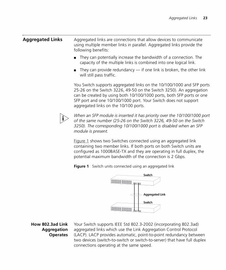
Aggregated Links Aggregated links are connections that allow devices to communicate using multiple member links in parallel. Aggregated links provide the following benefits:
■ They can potentially increase the bandwidth of a connection. The capacity of the multiple links is combined into one logical link.
■ They can provide redundancy — if one link is broken, the other link will still pass traffic.
You Switch supports aggregated links on the 10/100/1000 and SFP ports 25-26 on the Switch 3226, 49-50 on the Switch 3250). An aggregation can be created by using both 10/100/1000 ports, both SFP ports or one SFP port and one 10/100/1000 port. Your Switch does not support aggregated links on the 10/100 ports.
When an SFP module is inserted it has priority over the 10/100/1000 port of the same number (25-26 on the Switch 3226, 49-50 on the Switch 3250). The corresponding 10/100/1000 port is disabled when an SFP module is present.
Figure 1 shows two Switches connected using an aggregated link containing two member links. If both ports on both Switch units are configured as 1000BASE-TX and they are operating in full duplex, the potential maximum bandwidth of the connection is 2 Gbps.
Figure 1 Switch units connected using an aggregated link.
How 802.3ad LinkAggregation
Operates
Your Switch supports IEEE Std 802.3-2002 (incorporating 802.3ad) aggregated links which use the Link Aggregation Control Protocol (LACP). LACP provides automatic, point-to-point redundancy between two devices (switch-to-switch or switch-to-server) that have full duplex connections operating at the same speed.
Switch
Switch
Aggregated Link
24 CHAPTER 2: OPTIMIZING BANDWIDTH
By default, LACP is disabled on all Switch ports.
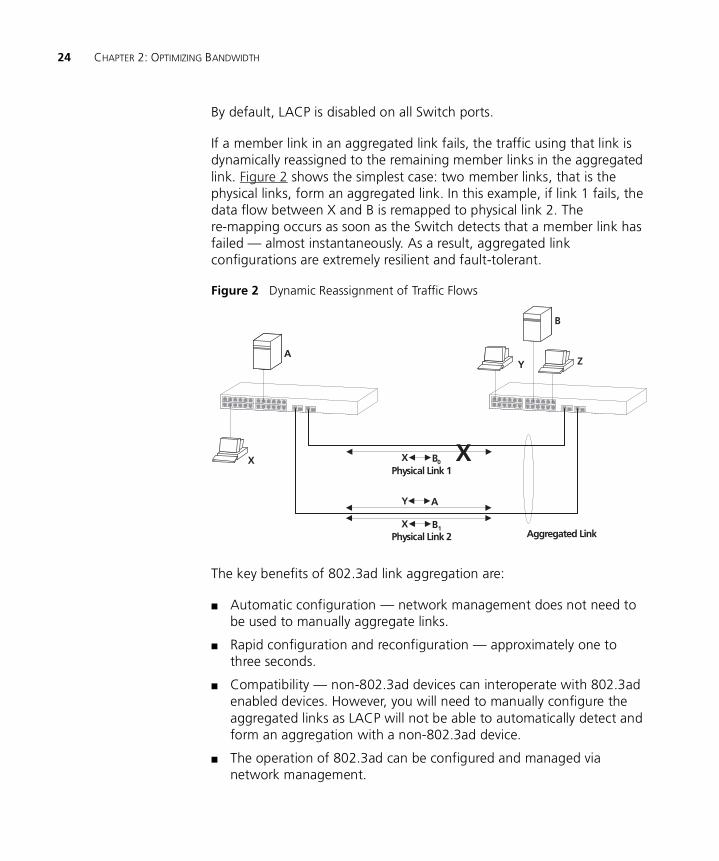
If a member link in an aggregated link fails, the traffic using that link is dynamically reassigned to the remaining member links in the aggregated link. Figure 2 shows the simplest case: two member links, that is the physical links, form an aggregated link. In this example, if link 1 fails, the data flow between X and B is remapped to physical link 2. The re-mapping occurs as soon as the Switch detects that a member link has failed — almost instantaneously. As a result, aggregated link configurations are extremely resilient and fault-tolerant.
Figure 2 Dynamic Reassignment of Traffic Flows
The key benefits of 802.3ad link aggregation are:
■ Automatic configuration — network management does not need to be used to manually aggregate links.
■ Rapid configuration and reconfiguration — approximately one to three seconds.
■ Compatibility — non-802.3ad devices can interoperate with 802.3ad enabled devices. However, you will need to manually configure the aggregated links as LACP will not be able to automatically detect and form an aggregation with a non-802.3ad device.
■ The operation of 802.3ad can be configured and managed via network management.
A
X
Y
B
Z
Aggregated Link
Physical Link 1
Physical Link 2X B1
X B0
Y A
X
Aggregated Links 25
Implementing802.3ad Aggregated
Links
LACP can be enabled or disabled on a per port basis. You can implement 802.3ad aggregated links in two ways:
■ Manual Aggregations — You can manually add and remove ports to and from an aggregated link via Web commands. However, if a port has LACP enabled, and if a more appropriate or correct automatic membership is detected by LACP, it will override the manual configuration.
■ LACP Automatic Aggregations — If LACP detects the two active ports sharing the same partner device, and if no matching pre-configured aggregated links exist, LACP will automatically assign both ports to form an aggregated link with the partner device.
If you have an existing single port connection between two devices, this automatic behavior allows quick and easy addition of extra bandwidth by simply adding an extra physical link between the units.
The Spanning Tree costs for a port running LACP is the cost assigned for an aggregated link running at that speed. As required by the IEEE Std 802.3-2002 (incorporating 802.3ad), no changes in cost are made according to the number of member links in the aggregated link.
Aggregated Links andYour Switch
When any port is assigned to an aggregated link (either manually or via LACP) it will adopt the configuration settings of the aggregated link. When a port leaves an aggregated link its original configuration settings are restored.
■ Your Switch supports a single aggregated link comprising:
■ both 10/100/1000 ports
or
■ both SFP ports
or
■ one SFP port and one 10/100/1000 port
■ A LinkUp / LinkDown trap will only be sent for individual links. The Traps will not be sent for an aggregation.
When setting up an aggregated link, note that:
■ The ports at both ends of a member link must be configured as members of an aggregated link, if you are manually configuring aggregated links.
26 CHAPTER 2: OPTIMIZING BANDWIDTH
■ A member link port can only belong to one aggregated link.
■ The member link ports can be mixed media, that is fiber and/or twisted pair ports within the same aggregated link.
■ The member link ports must have the same configuration.
When using an aggregated link, note that:
■ To gather statistics about an aggregated link, you must add together the statistics for each port in the aggregated link.
■ If you wish to disable a single member link of an aggregated link, you must first physically remove the connection to ensure that you do not lose any traffic, before you disable both ends of the member link separately. If you do this, the traffic destined for that link is distributed to the other links in the aggregated link.
■ Before removing an entire aggregated link, you must disable all the aggregated link ports or disconnect all the links, except one — if you do not, a loop may be created.
■ When manually creating an aggregated link between two devices, the ports in the aggregated link must not be physically connected together until the aggregated link has been correctly configured at both ends of the link. Failure to configure the aggregated link at both ends before physically connecting the ports can result in a number of serious network issues such as lost packets and network loops.
Traffic Distribution and Link Failure on Aggregated Links
To maximize throughput, all traffic is distributed across the individual links that make up an aggregated link. Therefore, when a packet is made available for transmission down an aggregated link, a hardware-based traffic distribution mechanism determines which particular port in the link should be used. The traffic is distributed among the member links as efficiently as possible.
To avoid the potential problem of out-of-sequence packets (or “packet re-ordering”), the Switch ensures that all the conversations between a given pair of endstations will pass through the same port in the aggregated link. Single-to-multiple endstation conversations, on the other hand, may still take place over different ports.
If the link state on any of the ports in an aggregated link becomes inactive due to link failure, then the Switch will automatically redirect the
Aggregated Links 27
aggregated link traffic to the remaining ports. Aggregated links therefore provide built-in resilience for your network.
The Switch also has a mechanism to prevent the possible occurrence of packet re-ordering when a link recovers too soon after a failure.
Aggregated Link —Manual
ConfigurationExample
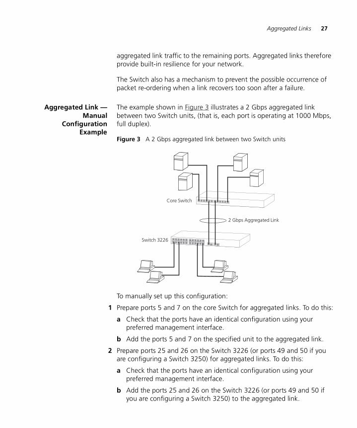
The example shown in Figure 3 illustrates a 2 Gbps aggregated link between two Switch units, (that is, each port is operating at 1000 Mbps, full duplex).
Figure 3 A 2 Gbps aggregated link between two Switch units
To manually set up this configuration:
1 Prepare ports 5 and 7 on the core Switch for aggregated links. To do this:
a Check that the ports have an identical configuration using your preferred management interface.
b Add the ports 5 and 7 on the specified unit to the aggregated link.
2 Prepare ports 25 and 26 on the Switch 3226 (or ports 49 and 50 if you are configuring a Switch 3250) for aggregated links. To do this:
a Check that the ports have an identical configuration using your preferred management interface.
b Add the ports 25 and 26 on the Switch 3226 (or ports 49 and 50 if you are configuring a Switch 3250) to the aggregated link.
28 CHAPTER 2: OPTIMIZING BANDWIDTH
3 Connect port 5 on the core Switch to port 25 on the Switch 3226.
4 Connect port 7 on the upper Switch to port 26 on the Switch 3226.
3
USING MULTICAST FILTERINGMulticast filtering improves the performance of networks that carry multicast traffic.
This chapter explains multicasts, multicast filtering, and how multicast filtering can be implemented on your Switch. It covers the following topics:
■ What is an IP Multicast?
■ Multicast Filtering
■ Multicast Filtering and Your Switch
For detailed descriptions of the Web interface operations and the Command Line Interface (CLI) commands that you require to manage the Switch please refer to the Management Interface Reference Guide supplied in HTML format on the CD-ROM that accompanies your Switch.
What is an IP Multicast?
A multicast is a packet that is intended for “one-to-many” and “many- to-many” communication. Users explicitly request to participate in the communication by joining an endstation to a specific multicast group. If the network is set up correctly, a multicast can only be sent to an endstation or a subset of endstations in a LAN, or VLAN, that belong to the relevant multicast group.
Multicast group members can be distributed across multiple subnetworks; thus, multicast transmissions can occur within a campus LAN or over a WAN. In addition, networks that support IP multicast send only one copy of the desired information across the network until the delivery path that reaches group members diverges. It is only at these points that multicast packets are replicated and forwarded, which makes efficient use of network bandwidth.
30 CHAPTER 3: USING MULTICAST FILTERING
A multicast packet is identified by the presence of a multicast group address in the destination address field of the packet’s IP header.
Benefits of Multicast The benefits of using IP multicast are that it:
■ Enables the simultaneous delivery of information to many receivers in the most efficient, logical way.
■ Reduces the load on the source (for example, a server) because it does not have to produce multiple copies of the same data.
■ Makes efficient use of network bandwidth and scales well as the number of participants or collaborators expands.
■ Works with other IP protocols and services, such as Quality of Service (QoS).
There are situations where a multicast approach is more logical and efficient than a unicast approach. Application examples include distance learning, transmitting stock quotes to brokers, and collaborative computing.
A typical use of multicasts is in video-conferencing, where high volumes of traffic need to be sent to several endstations simultaneously, but where broadcasting that traffic to all endstations would seriously reduce network performance.
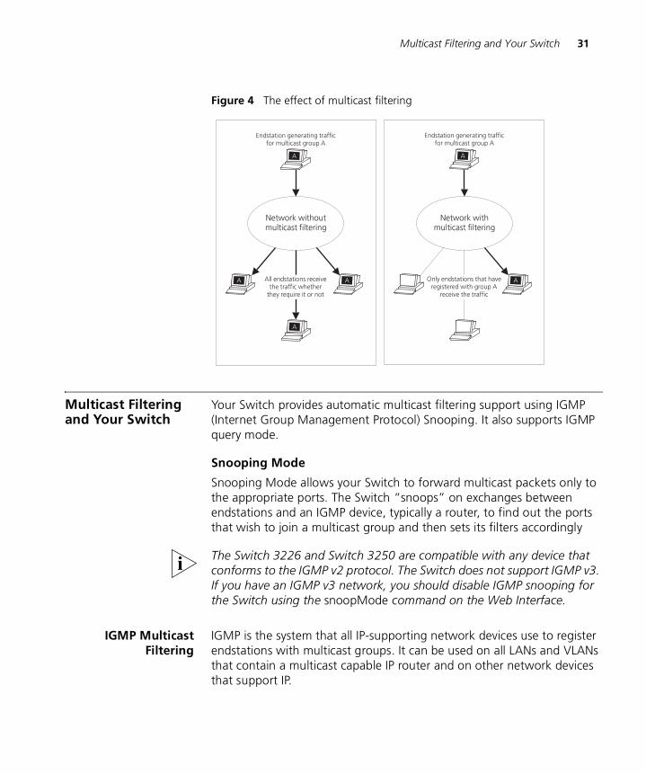
Multicast Filtering Multicast filtering is the process that ensures that endstations only receive multicast traffic if they register to join specific multicast groups. With multicast filtering, network devices only forward multicast traffic to the ports that are connected to registered endstations.
Multicast filtering is used to restrict multicasts within a VLAN. It does not route multicasts between different VLANs.
Figure 4 shows how a network behaves without multicast filtering and with multicast filtering.
Multicast Filtering and Your Switch 31
Figure 4 The effect of multicast filtering
Multicast Filtering and Your Switch
Your Switch provides automatic multicast filtering support using IGMP (Internet Group Management Protocol) Snooping. It also supports IGMP query mode.
Snooping Mode
Snooping Mode allows your Switch to forward multicast packets only to the appropriate ports. The Switch “snoops” on exchanges between endstations and an IGMP device, typically a router, to find out the ports that wish to join a multicast group and then sets its filters accordingly
The Switch 3226 and Switch 3250 are compatible with any device that conforms to the IGMP v2 protocol. The Switch does not support IGMP v3. If you have an IGMP v3 network, you should disable IGMP snooping for the Switch using the snoopMode command on the Web Interface.
IGMP MulticastFiltering
IGMP is the system that all IP-supporting network devices use to register endstations with multicast groups. It can be used on all LANs and VLANs that contain a multicast capable IP router and on other network devices that support IP.
32 CHAPTER 3: USING MULTICAST FILTERING
IGMP multicast filtering works as follows:
1 The IP router (or querier) periodically sends query packets to all the endstations in the LANs or VLANs that are connected to it. If your network has more than one IP router, then the one with the lowest IP address becomes the querier.
2 When an IP endstation receives a query packet, it sends a report packet back that identifies the multicast group that the endstation would like to join.
3 When the report packet arrives at a port on a Switch with IGMP multicast learning enabled, the Switch learns that the port is to forward traffic for the multicast group and then forwards the packet to the router.
4 When the router receives the report packet, it registers that the LAN or VLAN requires traffic for the multicast groups.
5 When the router forwards traffic for the multicast group to the LAN or VLAN, the Switch units only forward the traffic to ports that received a report packet.
Enabling IGMP Multicast Learning
You can enable or disable multicast learning using the Bridge > Multicast Filtering > IGMP > snoopMode command on the Web interface. For more information about enabling IGMP multicast learning, please refer to the Management Interface Reference Guide supplied on your Switch CD-ROM.
If IGMP multicast learning is not enabled then IP multicast traffic is always forwarded, that is, it floods the network.
For information about configuring IGMP functionality on an endstation, refer to the user documentation supplied with your endstation or the endstation’s Network Interface Card (NIC).
How IGMP SupportsIP Multicast
IGMP provides a way for routers and switches to learn where group members exist on a network, and thus provides a critical function in the IP multicast packet delivery process.
Electing the Querier
On each subnetwork or broadcast domain (VLAN), the communication between routers, switches, and group members begins with one IGMP-capable device being elected as the querier - that is, the device that asks all hosts to respond with a report of the IP multicast groups that they
Multicast Filtering and Your Switch 33
wish to join or to which they already belong. The querier is always the device with the lowest IP address in the subnetwork. It can be a router or a Layer 2 switch. The network traffic flows most efficiently if the querier is the closest device to the sources of IP multicast traffic.
Query Messages
The querier normally sends messages called IGMP Host Membership Query Messages, or queries, every 125 seconds. All the hosts hear the query because it is addressed to 224.0.0.1, the multicast address for all systems on the subnetwork. A query is not forwarded beyond the subnetwork from which it originates.
Host Messages
Hosts use IGMP to build their own types of IP multicast messages, as described in this section.
Response to Queries
Hosts respond to queries with IGMP Host Membership Report messages (IGMP reports). These reports do not travel beyond their origin subnetworks, and hosts send them at random intervals to prevent the querier from being overwhelmed.
A host sends a separate report for each group that it wants to join or to which it currently belongs. Hosts do not send reports if they are not group members.
If a router does not receive at least one host report for a particular group after two queries, the router assumes that members no longer exist and it prunes the interface for that source-group spanning tree.
Join Message
Rather than wait for a query, a host can also send an IGMP report on its own initiative to inform the querier that it wants to begin receiving a transmission for a specific group. This is called a join message. The benefit is faster transmission linkages, especially if the host is the first group member on the subnetwork.
Leave-Group Messages
Leave-group messages are a type of host message defined in IGMP version 2. If a host wants to leave an IP multicast group, it issues a leave-group message addressed to 224.0.0.2, the multicast address for all
34 CHAPTER 3: USING MULTICAST FILTERING
routers on the subnetwork. Upon receiving such a message, the querier determines whether that host is the last group member on the subnetwork by issuing a group-specific query.
Leave-group messages reduce leave latency — that is, the time between when the last group member on a given subnetwork sends a report and when a router stops forwarding traffic for that group onto the subnetwork. This process conserves bandwidth. The alternative is for the router to wait for at least two queries to go unanswered before pruning that subnetwork from the delivery tree.
Role of IGMP in IPMulticast Filtering
To further refine the IP multicast delivery process and maximize bandwidth efficiency, the Switch filters IP multicast packets on appropriate ports using a process called IGMP snooping. Both bridged interfaces and routed interfaces record which ports receive host IGMP reports and then set their filters accordingly so that IP multicast traffic for particular groups is not forwarded on ports or VLANs that do not require it.
4
USING RESILIENCE FEATURESSetting up resilience on your network helps protect critical links against failure, protects against network loops, and reduces network downtime to a minimum.
The Switch provides resilient links using the Rapid Spanning Tree Protocol (RSTP). The protocol configures itself automatically based on the surrounding network and is compatible with switches that use either the Spanning Tree Protocol (STP) or RSTP.
For detailed descriptions of the Web interface operations and the Command Line Interface (CLI) commands that you require to manage the Switch please refer to the Management Interface Reference Guide supplied in HTML format on the CD-ROM that accompanies your Switch.
Rapid Spanning Tree Protocol
The Rapid Spanning Tree Protocol makes your network more resilient to link failure and also provides a protection from loops — one of the major causes of broadcast storms. RSTP is enabled by default on your Switch.
To be fully effective, RSTP or STP must be enabled on all Switches in your network.
RSTP provides the same functionality as STP. For details on how the two systems differ, see “How RSTP Differs to STP” on page 40.
The following sections explain more about STP and the protocol features supported by your Switch. They cover the following topics:
■ What is STP?
■ How STP Works
■ Using STP on a Network with Multiple VLANs
36 CHAPTER 4: USING RESILIENCE FEATURES
The protocol is a part of the IEEE Std 802.1w-2001, bridge specification. To explain RSTP more effectively, your Switch will be referred to as a bridge.
Rapid Spanning TreeProtocol (RSTP)
The Rapid Spanning Tree (RSTP) is an enhanced Spanning Tree feature. RSTP implements the Spanning Tree Algorithm and Protocol, as defined in the IEEE Std 802.1w-2001.
Some of the benefits of RSTP are:
■ Faster determination of the Active Spanning Tree topology throughout a bridged network.
■ Support for bridges with more than 256 ports.
■ Support for the Fast-Forwarding configuration of edge ports provided by the 'Fast Start' feature. Fast Start allows a port that is connected to an endstation to begin forwarding traffic after only 4 seconds. During this 4 seconds RSTP (or STP) will detect any misconfiguration that may cause a temporary loop and react accordingly.
■ Easy deployment throughout a legacy network, through backward compatibility:
■ it will default to sending 802.1D style BPDU's on a port if it receives packets of this format.
■ it is possible for some ports on a Switch to operate in RSTP (802.1w) mode, and other ports, for example those connected to a legacy Switch, to operate in STP (802.1D) mode.
■ you have an option to force your Switch to use the legacy 802.1D version of Spanning Tree, if required.
What is STP? STP (802.1D) is a bridge-based system that allows you to implement parallel paths for network traffic and uses a loop-detection process to:
■ Find and disable the less efficient paths (that is, the paths that have a lower bandwidth).
■ Enable one of the less efficient paths if the most efficient path fails.
RSTP provides the same functionality as STP. For details on how the two systems differ, see “How RSTP Differs to STP” on page 40.
What is STP? 37
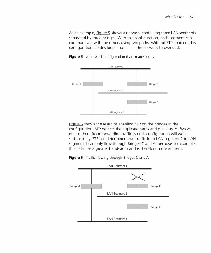
As an example, Figure 5 shows a network containing three LAN segments separated by three bridges. With this configuration, each segment can communicate with the others using two paths. Without STP enabled, this configuration creates loops that cause the network to overload.
Figure 5 A network configuration that creates loops
Figure 6 shows the result of enabling STP on the bridges in the configuration. STP detects the duplicate paths and prevents, or blocks, one of them from forwarding traffic, so this configuration will work satisfactorily. STP has determined that traffic from LAN segment 2 to LAN segment 1 can only flow through Bridges C and A, because, for example, this path has a greater bandwidth and is therefore more efficient.
Figure 6 Traffic flowing through Bridges C and A
38 CHAPTER 4: USING RESILIENCE FEATURES
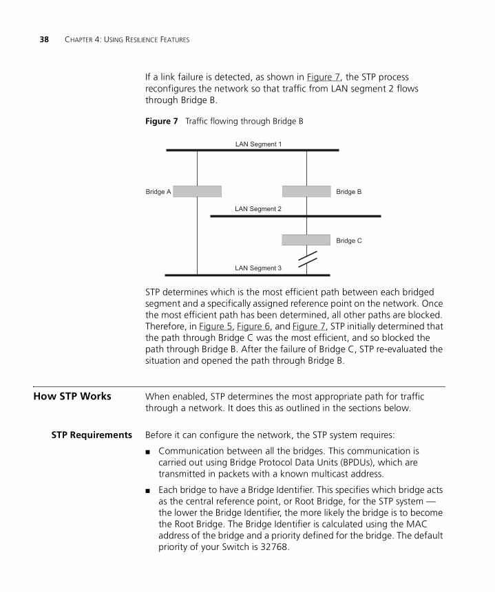
If a link failure is detected, as shown in Figure 7, the STP process reconfigures the network so that traffic from LAN segment 2 flows through Bridge B.
Figure 7 Traffic flowing through Bridge B
STP determines which is the most efficient path between each bridged segment and a specifically assigned reference point on the network. Once the most efficient path has been determined, all other paths are blocked. Therefore, in Figure 5, Figure 6, and Figure 7, STP initially determined that the path through Bridge C was the most efficient, and so blocked the path through Bridge B. After the failure of Bridge C, STP re-evaluated the situation and opened the path through Bridge B.
How STP Works When enabled, STP determines the most appropriate path for traffic through a network. It does this as outlined in the sections below.
STP Requirements Before it can configure the network, the STP system requires:
■ Communication between all the bridges. This communication is carried out using Bridge Protocol Data Units (BPDUs), which are transmitted in packets with a known multicast address.
■ Each bridge to have a Bridge Identifier. This specifies which bridge acts as the central reference point, or Root Bridge, for the STP system — the lower the Bridge Identifier, the more likely the bridge is to become the Root Bridge. The Bridge Identifier is calculated using the MAC address of the bridge and a priority defined for the bridge. The default priority of your Switch is 32768.
How STP Works 39
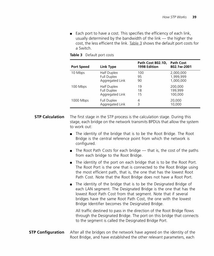
■ Each port to have a cost. This specifies the efficiency of each link, usually determined by the bandwidth of the link — the higher the cost, the less efficient the link. Table 3 shows the default port costs for a Switch.
Table 3 Default port costs
STP Calculation The first stage in the STP process is the calculation stage. During this stage, each bridge on the network transmits BPDUs that allow the system to work out:
■ The identity of the bridge that is to be the Root Bridge. The Root Bridge is the central reference point from which the network is configured.
■ The Root Path Costs for each bridge — that is, the cost of the paths from each bridge to the Root Bridge.
■ The identity of the port on each bridge that is to be the Root Port. The Root Port is the one that is connected to the Root Bridge using the most efficient path, that is, the one that has the lowest Root Path Cost. Note that the Root Bridge does not have a Root Port.
■ The identity of the bridge that is to be the Designated Bridge of each LAN segment. The Designated Bridge is the one that has the lowest Root Path Cost from that segment. Note that if several bridges have the same Root Path Cost, the one with the lowest Bridge Identifier becomes the Designated Bridge.
All traffic destined to pass in the direction of the Root Bridge flows through the Designated Bridge. The port on this bridge that connects to the segment is called the Designated Bridge Port.
STP Configuration After all the bridges on the network have agreed on the identity of the Root Bridge, and have established the other relevant parameters, each
Port Speed Link TypePath Cost 802.1D, 1998 Edition
Path Cost 802.1w-2001
10 Mbps Half DuplexFull DuplexAggregated Link
1009590
2,000,0001,999,9991,000,000
100 Mbps Half DuplexFull DuplexAggregated Link
191815
200,000199,999100,000
1000 Mbps Full DuplexAggregated Link
43
20,00010,000
40 CHAPTER 4: USING RESILIENCE FEATURES
bridge is configured to forward traffic only between its Root Port and the Designated Bridge Ports for the respective network segments. All other ports are blocked, which means that they are prevented from receiving or forwarding traffic.
STP Reconfiguration Once the network topology is stable, all the bridges listen for Hello BPDUs transmitted from the Root Bridge at regular intervals. If a bridge does not receive a Hello BPDU after a certain interval (the Max Age time), the bridge assumes that the Root Bridge, or a link between itself and the Root Bridge, has gone down. The bridge then reconfigures the network to cater for the change. If you have configured an SNMP trap destination, when the topology of your network changes, the first bridge to detect the change sends out an SNMP trap.
CAUTION: Network loops can occur if aggregated links are manually configured incorrectly, that is, the physical connections do not match the assignment of ports to an aggregated link. RSTP and STP may not detect these loops. So that RSTP and STP can detect all network loops you must ensure that all aggregated links are configured correctly.
How RSTP Differs toSTP
RSTP works in a similar way to STP, but it includes additional information in the BPDUs. This information allows each bridge to confirm that it has taken action to prevent loops from forming when it wants to enable a link to a neighbouring bridge. This allows adjacent bridges connected via point-to-point links to enable a link without having to wait to ensure all other bridges in the network have had time to react to the change.
So the main benefit of RSTP is that the configuration decision is made locally rather than network-wide which is why RSTP can carry out automatic configuration and restore a link faster than STP.
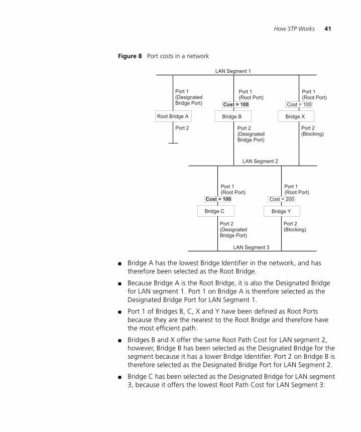
STP Example Figure 8 shows a LAN that has STP enabled. The LAN has three segments, and each segment is connected using two possible links.
How STP Works 41
Figure 8 Port costs in a network
■ Bridge A has the lowest Bridge Identifier in the network, and has therefore been selected as the Root Bridge.
■ Because Bridge A is the Root Bridge, it is also the Designated Bridge for LAN segment 1. Port 1 on Bridge A is therefore selected as the Designated Bridge Port for LAN Segment 1.
■ Port 1 of Bridges B, C, X and Y have been defined as Root Ports because they are the nearest to the Root Bridge and therefore have the most efficient path.
■ Bridges B and X offer the same Root Path Cost for LAN segment 2, however, Bridge B has been selected as the Designated Bridge for the segment because it has a lower Bridge Identifier. Port 2 on Bridge B is therefore selected as the Designated Bridge Port for LAN Segment 2.
■ Bridge C has been selected as the Designated Bridge for LAN segment 3, because it offers the lowest Root Path Cost for LAN Segment 3:
42 CHAPTER 4: USING RESILIENCE FEATURES
■ the route through Bridges C and B costs 200 (C to B=100, B to A=100)
■ the route through Bridges Y and B costs 300 (Y to B=200, B to A=100).
Port 2 on Bridge C is therefore selected as the Designated Bridge Port for LAN Segment 3.
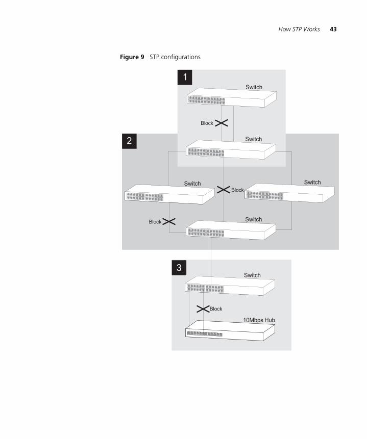
STP Configurations Figure 9 shows three possible STP configurations using SuperStack 3 Switch units.
■ Configuration 1 — Redundancy for Backbone Link
In this configuration, the Switches both have STP enabled and are connected by two links. STP discovers a duplicate path and blocks one of the links. If the enabled link breaks, the disabled link becomes re-enabled, therefore maintaining connectivity.
■ Configuration 2 — Redundancy through Meshed Backbone
In this configuration, four Switch units are connected in a way that creates multiple paths between each one. STP discovers the duplicate paths and blocks two of the links. If an enabled link breaks, one of the disabled links becomes re-enabled, therefore maintaining connectivity.
■ Configuration 3 — Redundancy for Cabling Error
In this configuration, a Switch has STP enabled and is accidentally connected to a hub using two links. STP discovers a duplicate path and blocks one of the links, therefore avoiding a loop.
How STP Works 43
Figure 9 STP configurations
44 CHAPTER 4: USING RESILIENCE FEATURES
Using STP on a Network with Multiple VLANs
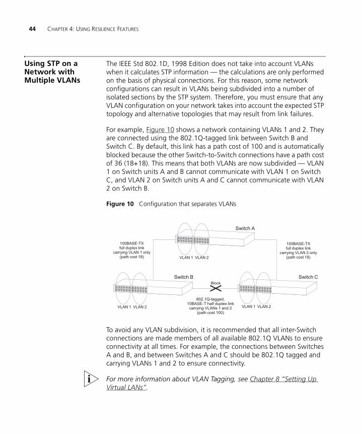
The IEEE Std 802.1D, 1998 Edition does not take into account VLANs when it calculates STP information — the calculations are only performed on the basis of physical connections. For this reason, some network configurations can result in VLANs being subdivided into a number of isolated sections by the STP system. Therefore, you must ensure that any VLAN configuration on your network takes into account the expected STP topology and alternative topologies that may result from link failures.
For example, Figure 10 shows a network containing VLANs 1 and 2. They are connected using the 802.1Q-tagged link between Switch B and Switch C. By default, this link has a path cost of 100 and is automatically blocked because the other Switch-to-Switch connections have a path cost of 36 (18+18). This means that both VLANs are now subdivided — VLAN 1 on Switch units A and B cannot communicate with VLAN 1 on Switch C, and VLAN 2 on Switch units A and C cannot communicate with VLAN 2 on Switch B.
Figure 10 Configuration that separates VLANs
To avoid any VLAN subdivision, it is recommended that all inter-Switch connections are made members of all available 802.1Q VLANs to ensure connectivity at all times. For example, the connections between Switches A and B, and between Switches A and C should be 802.1Q tagged and carrying VLANs 1 and 2 to ensure connectivity.
For more information about VLAN Tagging, see Chapter 8 “Setting Up Virtual LANs”.
5
USING THE SWITCH DATABASEWhat is the Switch Database?
The Switch Database is used by the Switch to determine where a packet should be forwarded to, and which port should transmit the packet if it is to be forwarded.
The database contains a list of entries — each entry contains three items:
■ MAC (Ethernet) address information of the endstation that sends packets to the Switch.
■ Port identifier, that is the port attached to the endstation that is sending the packet.
■ VLAN ID of the VLAN to which the endstation belongs.
For details of the number of addresses supported by your Switch database, please refer to Chapter 1 of the Getting Started Guide that accompanies your Switch.
For detailed descriptions of the Web interface operations and the Command Line Interface (CLI) commands that you require to manage the Switch please refer to the Management Interface Reference Guide supplied in HTML format on the CD-ROM that accompanies your Switch.
How Switch Database Entries Get Added
Entries are added to the Switch Database in one of two ways:
■ The Switch can learn entries. The Switch updates its database with the source MAC address of the endstation that sent the packet, the VLAN ID, and the port identifier on which the packet is received.
■ You can enter and update entries using the management interface via the Bridge > Address Database Web interface operation, or an SNMP Network Manager.
46 CHAPTER 5: USING THE SWITCH DATABASE
Switch Database Entry States
Databases entries can have three states:
■ Learned — The Switch has placed the entry into the Switch Database when a packet was received from an endstation. Note that:
■ Learned entries are removed (aged out) from the Switch Database if the Switch does not receive further packets from that endstation within a certain period of time (the aging time). This prevents the Switch Database from becoming full with obsolete entries by ensuring that when an endstation is removed from the network, its entry is also removed from the database.
■ Learned entries are removed from the Switch Database if the Switch is reset or powered-down.
■ Non-aging learned — If the aging time is set to 0 seconds, all learned entries in the Switch Database become non-aging learned entries. This means that they are not aged out, but they are still removed from the database if the Switch is reset or powered-down.
■ Permanent — The entry has been placed into the Switch Database using the management interface. Permanent entries are not removed from the Switch Database unless they are removed using the Switch management interface via the bridge > addressDatabase > remove Web operation or the Switch is initialized.
6
USING TRAFFIC MANAGEMENTUsing the traffic management capabilities of your Switch allows your network traffic to be controlled and prioritized to ensure that high priority data is transmitted with minimum delay.
The Switch 3226 and Switch 3250 have two features that allow you to manage the traffic on your network:
■ Traffic Prioritization — Ensures that important data is forwarded promptly by the Switch without delay. See “What is Traffic Prioritization?” below.
■ Rate Limiting — Keeps your core network traffic down by setting a maximum traffic rate on a port by port basis. See “Limiting the Rate of a Port” on page 52.
What is Traffic Prioritization?
Traffic prioritization allows high priority data, such as time-sensitive and system-critical data to be transferred smoothly and with minimal delay over a network.
Traffic prioritization is most useful for critical applications that require a high level of service from the network. These could include:
■ Converged network applications — Used by organizations with a converged network, that is, a network that uses the same infrastructure for voice and video data and traditional data. Organizations that require high quality voice and video data transmission at all times can ensure this by maximizing bandwidth and providing low latency.
■ Resource planning applications — Used by organizations that require predictable and reliable access to enterprise resource planning applications such as SAP.
48 CHAPTER 6: USING TRAFFIC MANAGEMENT
■ Financial applications — Used by Accounts departments that need immediate access to large files and spreadsheets.
■ CAD/CAM design applications — Used by design departments that need priority connections to server farms and other devices for transferring large files.
How Traffic Prioritization Works
Traffic prioritization ensures that high priority data is forwarded through the Switch without being delayed by lower priority data. Traffic prioritization uses the four traffic queues that are present in the hardware of the Switch to ensure that high priority traffic is forwarded on a different queue from lower priority traffic. High priority traffic is given preference over low priority traffic to ensure that the most critical traffic gets the highest level of service.
The Switch employs three methods of classifying traffic for prioritization. Traffic classification is the means of identifying which application generated the traffic, so that a service level can be applied to it.
The three supported methods for classifying traffic are:
■ 802.1D (classification is done at layer 2 of the OSI model).
■ DiffServ code point (classification is done at layer 3 of the OSI model).
■ IP Port (classification is done at layer 4 of the OSI model).
These methods can be used together. If a packet is prioritized differently by different methods then it will be tagged with the higher priority.
802.1D trafficclassification
At layer 2, a traffic service class is defined in an 802.1Q frame, which is able to carry VLAN identification and user priority information. The information is carried in a header field immediately following the destination MAC address, and Source MAC address.
802.1D Priority Levels
The traffic prioritization feature supported by the Switch at layer 2 is compatible with the relevant sections of the IEEE 802.1D/D17 standard (incorporating IEEE 802.1p). Once a packet has been classified, the level of service relevant to that type of packet is applied to it.
How Traffic Prioritization Works 49
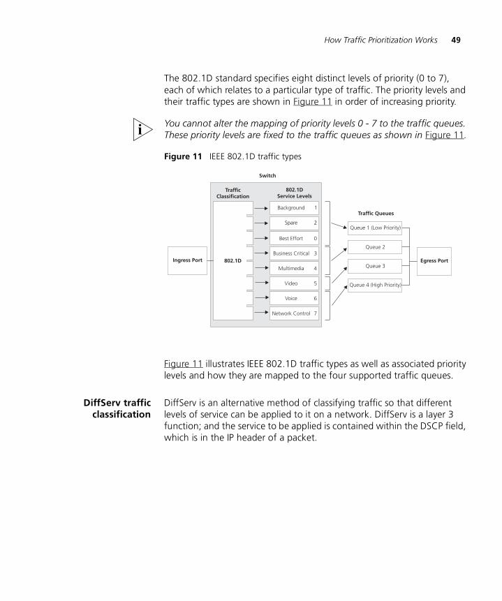
The 802.1D standard specifies eight distinct levels of priority (0 to 7), each of which relates to a particular type of traffic. The priority levels and their traffic types are shown in Figure 11 in order of increasing priority.
You cannot alter the mapping of priority levels 0 - 7 to the traffic queues. These priority levels are fixed to the traffic queues as shown in Figure 11.
Figure 11 IEEE 802.1D traffic types
Figure 11 illustrates IEEE 802.1D traffic types as well as associated priority levels and how they are mapped to the four supported traffic queues.
DiffServ trafficclassification
DiffServ is an alternative method of classifying traffic so that different levels of service can be applied to it on a network. DiffServ is a layer 3 function; and the service to be applied is contained within the DSCP field, which is in the IP header of a packet.
50 CHAPTER 6: USING TRAFFIC MANAGEMENT
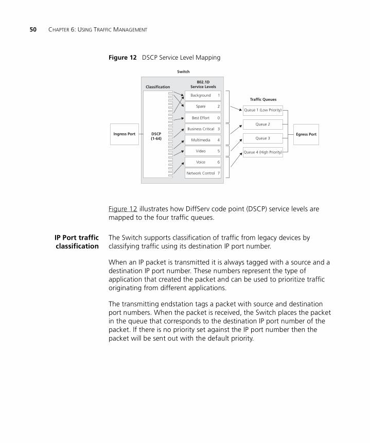
Figure 12 DSCP Service Level Mapping
Figure 12 illustrates how DiffServ code point (DSCP) service levels are mapped to the four traffic queues.
IP Port trafficclassification
The Switch supports classification of traffic from legacy devices by classifying traffic using its destination IP port number.
When an IP packet is transmitted it is always tagged with a source and a destination IP port number. These numbers represent the type of application that created the packet and can be used to prioritize traffic originating from different applications.
The transmitting endstation tags a packet with source and destination port numbers. When the packet is received, the Switch places the packet in the queue that corresponds to the destination IP port number of the packet. If there is no priority set against the IP port number then the packet will be sent out with the default priority.
Traffic Prioritization and your Switch 51
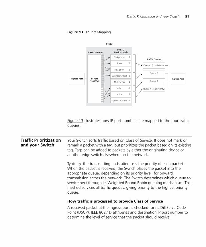
Figure 13 IP Port Mapping
Figure 13 illustrates how IP port numbers are mapped to the four traffic queues.
Traffic Prioritization and your Switch
Your Switch sorts traffic based on Class of Service. It does not mark or remark a packet with a tag, but prioritizes the packet based on its existing tag. Tags can be added to packets by either the originating device or another edge switch elsewhere on the network.
Typically, the transmitting endstation sets the priority of each packet. When the packet is received, the Switch places the packet into the appropriate queue, depending on its priority level, for onward transmission across the network. The Switch determines which queue to service next through its Weighted Round Robin queuing mechanism. This method services all traffic queues, giving priority to the highest priority queue.
How traffic is processed to provide Class of Service
A received packet at the ingress port is checked for its DiffServe Code Point (DSCP), IEEE 802.1D attributes and destination IP port number to determine the level of service that the packet should receive.
52 CHAPTER 6: USING TRAFFIC MANAGEMENT
802.1D packets are categorized into the eight traffic classes defined by IEEE 802.1D; the higher the class the higher the priority given to the packet on transmission. See Figure 11.
DSCP packets are categorized into the six service levels as shown in Figure 12 and mapped to the appropriate queue.
The priority defined in the service level directs the packet to the appropriate egress queue. When a packet comes in with more than one marking the markings are ranked as follows:
1 IP Port — if the destination IP port of the packet has been allocated a CoS value then the packet is prioritized by that value.
2 DSCP — if the packet is marked with a DSCP value and if that value is enabled then the packet is prioritized with the corresponding priority.
3 IEEE 802.1D — If the packet is marked with an IEEE 802.1D traffic type then this will be used to prioritize the packet.
Configuring traffic prioritization
CoS can be configured on your Switch using the Web interface or via the Command Line Interface (CLI).
For a detailed description of the commands that you require to configure CoS refer to the Management Interface Reference Guide supplied in HTML format on the CD-ROM that accompanies your Switch.
Limiting the Rate of a Port
Limiting the rate at which a port can receive or send traffic can be used to ease congestion on bottlenecks in your network and provide simple prioritization when the network is busy.
Rate limiting is commonly used in the following situations:
■ To prevent a high bandwidth client or group of clients from dominating the traffic on your network.
■ To balance the traffic at a bottleneck, such as an external-facing router, so that different departments or parts of your network get similar access across the bottleneck.
The advantage of rate limiting is that it is a simple solution: it is easy to set up and maintain. It can be used to effectively keep the traffic on your network to a manageable level.
Limiting the Rate of a Port 53
Configuring rate limiting
Rate limiting can be configured on your Switch using the Web interface or the Command Line Interface (CLI).
Rate limiting can be applied in steps of 1 Mb on 10/100 ports and in steps of 8 Mb on 10/100/1000 ports.
For a detailed description of the commands that you require to configure rate limiting refer to the Management Interface Reference Guide supplied in HTML format on the CD-ROM that accompanies your Switch.
Traffic Prioritizationand Rate Limiting
Traffic prioritization and rate limiting can be used together to effectively manage the traffic on your network:
■ Rate limiting will ensure that the traffic on a connection never exceeds the rate you specify.
■ Traffic prioritization will ensure that any packets dropped at times of network congestion are of the lowest priority.
Traffic prioritization and rate limiting are most effective together if the egress rate rather than the ingress rate is limited on a port; that is the traffic rate leaving the Switch is limited rather than the traffic arriving at the Switch. This ensures that the traffic is prioritized before rate limiting is applied, and that the lowest priority packets are dropped first.
Rate limiting on ingress, as the packets arrive at the port is not as effective. The Switch cannot determine the order in which packets will arrive and will not filter by priority.

54 CHAPTER 6: USING TRAFFIC MANAGEMENT
7
STATUS MONITORING AND STATISTICSThis chapter contains details of the Remote Monitoring (RMON) feature that assists you with status monitoring and statistics.
For detailed descriptions of the Web interface operations and the Command Line Interface (CLI) commands that you require to manage the Switch please refer to the Management Interface Reference Guide supplied in HTML format on the CD-ROM that accompanies your Switch.
RMON Using the RMON capabilities of a Switch allows you to improve your network efficiency and reduce the load on your network.
This section explains more about RMON. It covers the following topics:
■ What is RMON?
■ Benefits of RMON
■ RMON and the Switch
What is RMON? RMON is a system defined by the IETF (Internet Engineering Task Force) that allows you to monitor the traffic of LANs or VLANs.
RMON is an integrated part of the Switch software agent and continually collects statistics about a LAN segment or VLAN, and transfers the information to a management workstation on request or when a pre-defined threshold is crossed. The workstation does not have to be on the same network as the Switch and can manage the Switch by in-band or out-of-band connections.
The RMON Groups The IETF define groups of Ethernet RMON statistics. This section describes the four groups supported by the Switch, and details how you can use them.
56 CHAPTER 7: STATUS MONITORING AND STATISTICS
Statistics
The Statistics group provides traffic and error statistics showing packets, bytes, broadcasts, multicasts and errors on a LAN segment or VLAN.
Information from the Statistics group is used to detect changes in traffic and error patterns in critical areas of your network.
History
The History group provides historical views of network performance by taking periodic samples of the counters supplied by the Statistics group.
The group is useful for analyzing the traffic patterns and trends on a LAN segment or VLAN, and for establishing the normal operating parameters of your network.
Alarms
The Alarms group provides a mechanism for setting thresholds and sampling intervals to generate events on any RMON variable.
Alarms are used to inform you of network performance problems and they can trigger automated responses through the Events group.
Events
The Events group provides you with the ability to create entries in an event log and send SNMP traps to the management workstation. Events are the action that can result from an RMON alarm. In addition to the standard five traps required by SNMP (link up, link down, warm start, cold start, and authentication failure), RMON adds two more: rising threshold and falling threshold.
Effective use of the Events group saves you time; rather than having to watch real-time graphs for important occurrences, you can depend on the Event group for notification. Through the SNMP traps, events can trigger other actions, therefore providing a way to automatically respond to certain occurrences.
Benefits of RMON 57
Benefits of RMON Using the RMON features of your Switch has three main advantages:
■ It improves your efficiency
Using RMON allows you to remain at one workstation and collect information from widely dispersed LAN segments or VLANs. This means that the time taken to reach a problem site, set up equipment, and begin collecting information is largely eliminated.
■ It allows you to manage your network in a more proactive manner
If configured correctly, RMON can deliver information before problems occur. This means that you can take action before they affect users. In addition, probes record the behavior of your network, so that you can analyze the causes of problems.
■ It reduces the load on the network and the management workstation
Traditional network management involves a management workstation polling network devices at regular intervals to gather statistics and identify problems or trends. As network sizes and traffic levels grow, this approach places a strain on the management workstation and also generates large amounts of traffic.
RMON, however, autonomously looks at the network on behalf of the management workstation without affecting the characteristics and performance of the network. RMON reports by exception, which means that it only informs the management workstation when the network has entered an abnormal state.
RMON and the Switch
The RMON support provided by your Switch 3226 and Switch 3250 is detailed in Table 4.
Table 4 RMON support supplied by the Switch
RMON group Support supplied by the Switch
Statistics A new or initialized Switch has one Statistics session per port.
History A new or initialized Switch has two History sessions per port.
These sessions provide the data for the Web interface history displays:
■ 10 min intervals, 6 historical samples stored
■ 1 hour intervals, 6 historical samples stored
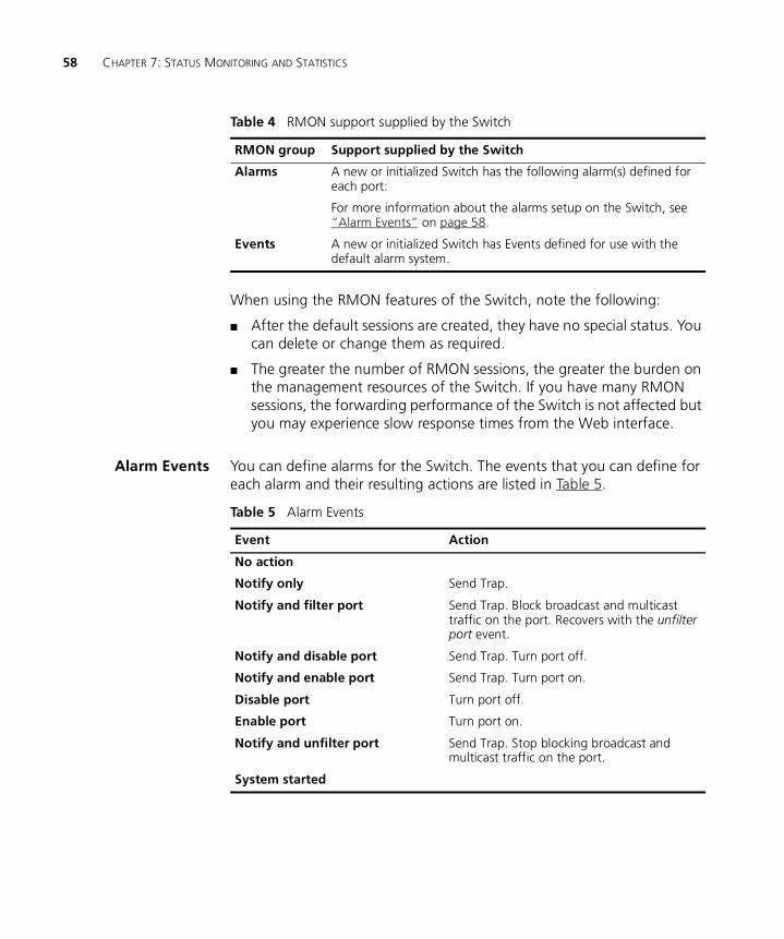
58 CHAPTER 7: STATUS MONITORING AND STATISTICS
When using the RMON features of the Switch, note the following:
■ After the default sessions are created, they have no special status. You can delete or change them as required.
■ The greater the number of RMON sessions, the greater the burden on the management resources of the Switch. If you have many RMON sessions, the forwarding performance of the Switch is not affected but you may experience slow response times from the Web interface.
Alarm Events You can define alarms for the Switch. The events that you can define for each alarm and their resulting actions are listed in Table 5.
Alarms A new or initialized Switch has the following alarm(s) defined for each port:
For more information about the alarms setup on the Switch, see “Alarm Events” on page 58.
Events A new or initialized Switch has Events defined for use with the default alarm system.
Table 4 RMON support supplied by the Switch
RMON group Support supplied by the Switch
Table 5 Alarm Events
Event Action
No action
Notify only Send Trap.
Notify and filter port Send Trap. Block broadcast and multicast traffic on the port. Recovers with the unfilter port event.
Notify and disable port Send Trap. Turn port off.
Notify and enable port Send Trap. Turn port on.
Disable port Turn port off.
Enable port Turn port on.
Notify and unfilter port Send Trap. Stop blocking broadcast and multicast traffic on the port.
System started
8
SETTING UP VIRTUAL LANSSetting up Virtual LANs (VLANs) on your Switch increases the efficiency of your network by dividing the LAN into logical, rather than physical, segments which are easier to manage.
This chapter explains more about the concept of VLANs and explains how they can be implemented on your Switch. It covers the following topics:
■ What are VLANs?
■ Benefits of VLANs
■ VLANs and Your Switch
■ VLAN Configuration Examples
For detailed descriptions of the Web interface operations and the Command Line Interface (CLI) commands that you require to manage the Switch please refer to the Management Interface Reference Guide supplied in HTML format on the CD-ROM that accompanies your Switch.
What are VLANs? A VLAN is a flexible group of devices that can be located anywhere in a network, but which communicate as if they are on the same physical segment. With VLANs, you can segment your network without being restricted by physical connections — a limitation of traditional network design. As an example, with VLANs you can segment your network according to:
■ Departmental groups — For example, you can have one VLAN for the Marketing department, another for the Finance department, and another for the Development department.
■ Hierarchical groups — For example, you can have one VLAN for directors, another for managers, and another for general staff.
■ Usage groups — For example, you can have one VLAN for users of e-mail, and another for users of multimedia.
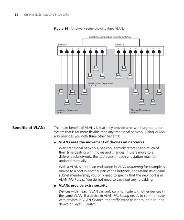
60 CHAPTER 8: SETTING UP VIRTUAL LANS
Figure 14 A network setup showing three VLANs
Benefits of VLANs The main benefit of VLANs is that they provide a network segmentation system that is far more flexible than any traditional network. Using VLANs also provides you with three other benefits:
■ VLANs ease the movement of devices on networks
With traditional networks, network administrators spend much of their time dealing with moves and changes. If users move to a different subnetwork, the addresses of each endstation must be updated manually.
With a VLAN setup, if an endstation in VLAN Marketing for example is moved to a port in another part of the network, and retains its original subnet membership, you only need to specify that the new port is in VLAN Marketing. You do not need to carry out any re-cabling.
■ VLANs provide extra security
Devices within each VLAN can only communicate with other devices in the same VLAN. If a device in VLAN Marketing needs to communicate with devices in VLAN Finance, the traffic must pass through a routing device or Layer 3 Switch.
VLAN 1
VLAN 3
VLAN 2Marketing Department
Development Department
Finance Department
Switch A Switch B
Backbone connecting multiple switches
1 12 23 34 45 56 67 78 8
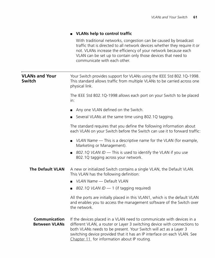
VLANs and Your Switch 61
■ VLANs help to control traffic
With traditional networks, congestion can be caused by broadcast traffic that is directed to all network devices whether they require it or not. VLANs increase the efficiency of your network because each VLAN can be set up to contain only those devices that need to communicate with each other.
VLANs and Your Switch
Your Switch provides support for VLANs using the IEEE Std 802.1Q-1998. This standard allows traffic from multiple VLANs to be carried across one physical link.
The IEEE Std 802.1Q-1998 allows each port on your Switch to be placed in:
■ Any one VLAN defined on the Switch.
■ Several VLANs at the same time using 802.1Q tagging.
The standard requires that you define the following information about each VLAN on your Switch before the Switch can use it to forward traffic:
■ VLAN Name — This is a descriptive name for the VLAN (for example, Marketing or Management).
■ 802.1Q VLAN ID — This is used to identify the VLAN if you use 802.1Q tagging across your network.
The Default VLAN A new or initialized Switch contains a single VLAN, the Default VLAN. This VLAN has the following definition:
■ VLAN Name — Default VLAN
■ 802.1Q VLAN ID — 1 (if tagging required)
All the ports are initially placed in this VLAN1, which is the default VLAN and enables you to access the management software of the Switch over the network.
CommunicationBetween VLANs
If the devices placed in a VLAN need to communicate with devices in a different VLAN, a router or Layer 3 switching device with connections to both VLANs needs to be present. Your Switch will act as a Layer 3 switching device provided that it has an IP interface on each VLAN. See Chapter 11 for information about IP routing.
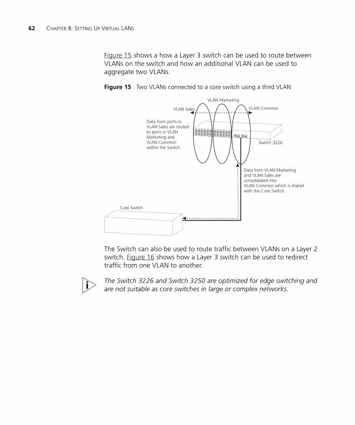
62 CHAPTER 8: SETTING UP VIRTUAL LANS
Figure 15 shows a how a Layer 3 switch can be used to route between VLANs on the switch and how an additional VLAN can be used to aggregate two VLANs.
Figure 15 Two VLANs connected to a core switch using a third VLAN
The Switch can also be used to route traffic between VLANs on a Layer 2 switch. Figure 16 shows how a Layer 3 switch can be used to redirect traffic from one VLAN to another.
The Switch 3226 and Switch 3250 are optimized for edge switching and are not suitable as core switches in large or complex networks.
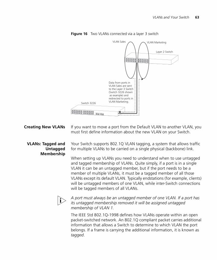
VLANs and Your Switch 63
Figure 16 Two VLANs connected via a layer 3 switch
Creating New VLANs If you want to move a port from the Default VLAN to another VLAN, you must first define information about the new VLAN on your Switch.
VLANs: Tagged andUntagged
Membership
Your Switch supports 802.1Q VLAN tagging, a system that allows traffic for multiple VLANs to be carried on a single physical (backbone) link.
When setting up VLANs you need to understand when to use untagged and tagged membership of VLANs. Quite simply, if a port is in a single VLAN it can be an untagged member, but if the port needs to be a member of multiple VLANs, it must be a tagged member of all those VLANs except its default VLAN. Typically endstations (for example, clients) will be untagged members of one VLAN, while inter-Switch connections will be tagged members of all VLANs.
A port must always be an untagged member of one VLAN. If a port has its untagged membership removed it will be assigned untagged membership of VLAN 1.
The IEEE Std 802.1Q-1998 defines how VLANs operate within an open packet-switched network. An 802.1Q compliant packet carries additional information that allows a Switch to determine to which VLAN the port belongs. If a frame is carrying the additional information, it is known as tagged.
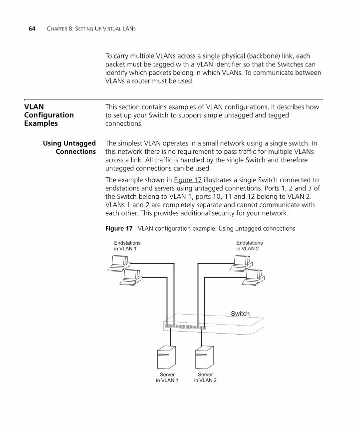
64 CHAPTER 8: SETTING UP VIRTUAL LANS
To carry multiple VLANs across a single physical (backbone) link, each packet must be tagged with a VLAN identifier so that the Switches can identify which packets belong in which VLANs. To communicate between VLANs a router must be used.
VLAN Configuration Examples
This section contains examples of VLAN configurations. It describes how to set up your Switch to support simple untagged and tagged connections.
Using UntaggedConnections
The simplest VLAN operates in a small network using a single switch. In this network there is no requirement to pass traffic for multiple VLANs across a link. All traffic is handled by the single Switch and therefore untagged connections can be used.
The example shown in Figure 17 illustrates a single Switch connected to endstations and servers using untagged connections. Ports 1, 2 and 3 of the Switch belong to VLAN 1, ports 10, 11 and 12 belong to VLAN 2. VLANs 1 and 2 are completely separate and cannot communicate with each other. This provides additional security for your network.
Figure 17 VLAN configuration example: Using untagged connections
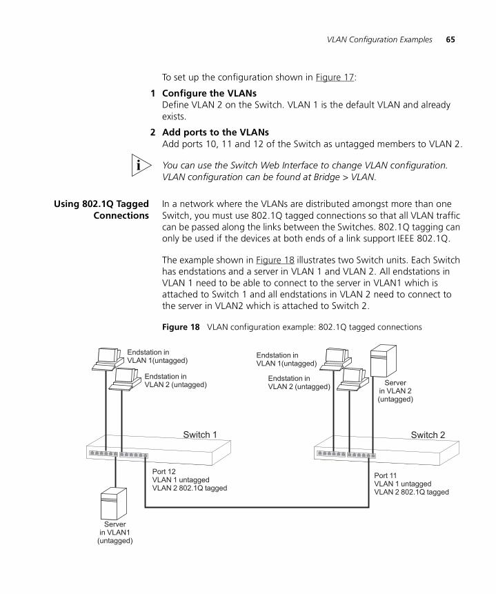
VLAN Configuration Examples 65
To set up the configuration shown in Figure 17:
1 Configure the VLANs Define VLAN 2 on the Switch. VLAN 1 is the default VLAN and already exists.
2 Add ports to the VLANsAdd ports 10, 11 and 12 of the Switch as untagged members to VLAN 2.
You can use the Switch Web Interface to change VLAN configuration. VLAN configuration can be found at Bridge > VLAN.
Using 802.1Q TaggedConnections
In a network where the VLANs are distributed amongst more than one Switch, you must use 802.1Q tagged connections so that all VLAN traffic can be passed along the links between the Switches. 802.1Q tagging can only be used if the devices at both ends of a link support IEEE 802.1Q.
The example shown in Figure 18 illustrates two Switch units. Each Switch has endstations and a server in VLAN 1 and VLAN 2. All endstations in VLAN 1 need to be able to connect to the server in VLAN1 which is attached to Switch 1 and all endstations in VLAN 2 need to connect to the server in VLAN2 which is attached to Switch 2.
Figure 18 VLAN configuration example: 802.1Q tagged connections

66 CHAPTER 8: SETTING UP VIRTUAL LANS
9
USING AUTOMATIC IP CONFIGURATIONThis chapter explains more about IP addresses and how the automatic configuration option works. It covers the following topics:
■ How Your Switch Obtains IP Information
■ How Automatic IP Configuration Works
■ Important Considerations
For detailed information on setting up your Switch for management, see the Getting Started Guide that accompanies your Switch.
For detailed descriptions of the Web interface operations and the Command Line Interface (CLI) commands that you require to manage the Switch please refer to the Management Interface Reference Guide supplied in HTML format on the CD-ROM that accompanies your Switch.
For background information on IP addressing, see Appendix C “IP Addressing”.
Automatic IP configuration only operates on the first IP interface of the Switch. Additional interfaces must be configured manually.
How Your Switch Obtains IP Information
Your Switch has two ways to obtain its IP address information:
■ Automatic IP Configuration (default) — the Switch attempts to configure itself by communicating with a DHCP server on the network.
■ Manual IP Configuration — you can manually input the IP information (IP address, subnet mask, and default gateway).
If you select an option for no IP configuration the Switch will not be accessible from a remote management workstation on the LAN. In addition, the Switch will not be able to respond to SNMP requests.
68 CHAPTER 9: USING AUTOMATIC IP CONFIGURATION
How Automatic IP Configuration Works
When your Switch is powered up for the first time the IP configuration setting is set to auto — this is the default setting.
If your Switch has been powered up before, whichever of the three options for IP configuration (manual, auto, none) was last configured is activated when the Switch powers up again.
You can switch to manual IP configuration at any time using a serial port connection to set up the IP information. For more information see the Getting Started Guide that accompanies your Switch.
Automatic Process To detect its IP information using the automatic configuration process, the Switch continually attempt to contact a DHCP server on the network requesting IP information from the server.
If a DHCP server is on the network and working correctly it responds to the clients request with an IP address (allocated from a pool of available addresses) and other parameters such as a subnet mask, default gateway, lease time, and any other options configured in the DHCP server.
The way a DHCP server responds is dependent on the DHCP server settings. Therefore the way your DHCP server responds may be different to the process outlined.
Important Considerations
This section contains some important points to note when using the automatic IP configuration feature.
The dynamic nature of automatically configured IP information means that a Switch may change its IP address whilst in use. Your DHCP server may allow you to reserve an IP address so that your Switch will always be allocated the same IP address.
Server Support Your Switch has been tested to interoperate with DHCP servers that use the following operating systems:
■ Microsoft Windows 2000 Server
■ Microsoft Windows NT4 Server
■ Sun Solaris v2.5.1
Important Considerations 69
If you want DHCP to be the method for automatic configuration, make sure that your DHCP servers are operating normally before you power on your Switch.

70 CHAPTER 9: USING AUTOMATIC IP CONFIGURATION
10
MAKING YOUR NETWORK SECUREThis chapter outlines the Port Security and Switch Management Login features, explains the key benefits of using these features, and gives examples of how and why you would use them in your network.
For detailed descriptions of the Web interface operations and the Command Line Interface (CLI) commands that you require to manage the Switch please refer to the Management Interface Reference Guide supplied in HTML format on the CD-ROM that accompanies your Switch.
Limiting Management Access by IP Address
The Switch 3226 and Switch 3250 can restrict management access to an IP address or range of IP addresses using the trusted IP feature.
You can allow an IP address or range of addresses access to one or more of the following interfaces:
■ HTTP
■ SSL (HTTPS)
■ SNMP
■ SSH
■ Telnet
Once you enable trusted IP, only those methods and IP addresses that you have allowed access will be able to manage the Switch. Attempts to access a management interface from un unauthorized addresses or using an unauthorized method will be denied.
Before enabling trusted IP 3Com recommends that you add the IP address of your management station to the list of trusted IP addresses.
The trusted IP feature restricts network access to the management interfaces of the Switch. You will be able to access the management
72 CHAPTER 10: MAKING YOUR NETWORK SECURE
interface of the Switch using console port, even if you have denied all access to the Switch using the trusted IP feature.
Securing Access to the Web Interface
The Switch 3226 and Switch 3250 support HTTPS, allowing secure access to the Web interface of the Switch.
If you adminster your switch remotely or over an insecure network, the Switch can encrypt all HTTP traffic to and from the Web interface using the Secure Sockets Layer (SSL) of HTTP. If your network traffic is intercepted, no passwords or configuration information will be visible in the data.
To use HTTPS you need the following:
■ A browser that supports SSL
■ A digital certificate installed on the Switch
The Switch ships with a default certificate installed. This certificate has not been validated by a Certifying Authority and your browser may warn you that certificate has not been certified. Using a properly validated certificate provides a higher level of security than the default certificate.
You can securely browse your Switch by using the HTTPS (HTTP over SSL) protocol. To access the Web interface securely, enter the following into your browser:
https://xxx.xxx.xxx.xxx/
where xxx.xxx.xxx.xxx is the IP address of your Switch.
Once you have set up your Switch to support HTTPS, you can optionally stop unencrypted administration by redirecting HTTP accesses (port 80) to port 443 (the port used by HTTPS). The Switch can be configured to redirect all attempts to administer the Web interface.
Getting a DigitalCertificate
Before accessing your Switch using HTTPS, you need an digital certificate which is used to identify your Switch. The Switch uses certificates that adhere to the following X.509 standard.
If you have the software to generate an X.509 certificate, you can self-certify your Switch. Administrators will be warned that the certificate
Securing Access to the Command Line Interface 73
has not been certified by a Certificate Authority (CA) but security will not be otherwise affected.
If you cannot generate an X.509 certificate yourself, you can buy one from one of the Certifying Authorities or your ISP. Each Switch requires its own X.509 certificate.
Securing Access to the Command Line Interface
The Switch 3226 and Switch 3250 support SSH (Secure Shell), allowing secure access to the Command Line Interface of the Switch.
If you use SSH to administer your Switch and the network traffic is intercepted, no passwords or configuration information will be visible in the data. To securely adminster the Switch using the Command Line Interface you need a Telnet/SSH client. You do not need a digital certificate as your Switch can generate its own.
To administer your Switch using SSH, start your Telnet/SSH client and enter the IP address of your Switch.
If your Telnet/SSH application supports both encrypted and unencrypted modes, make sure that you have SSH encryption set.
At time of writing, the Telnet client supplied with Windows does not support SSH.
Access Control Lists Access Control Lists (ACLs) are layer 3 instructions that can be used to filter traffic on network ports. They can be used to limit access to certain segments of the network, and therefore are useful for network security.
Access Control Lists can be used to:
■ Prevent unnecessary network traffic.
■ Restrict access to proprietary information within the network.
An ACL is made up of on a series of rules. Rules are applied to network ports and determine the access limitations for packets received on a network port. When a packet is received on a network port, it is compared to the ACL for the network port. If it matches, it will either be passed (permitted) or blocked (denied) depending on the rule.
74 CHAPTER 10: MAKING YOUR NETWORK SECURE
A maximum of 32 access lists can be applied under the current operating system. Access list rules can be applied and traffic is forwarded at wire speed using layer 3 destination IP addresses and network ports.
How Access ControlList Rules Work
When a packet is received on a port, it is compared against the ACL bound to that port. If the destination address of the packet lies within the address range of one of the ACL’s rules then that rule is applied. By default, if no access list has been defined for a network port, all IP traffic will be permitted. Denial is based on a pre-defined rule.
For example:
Packet destination IP address: 10.101.67.45
Rule destination address: 10.101.67.0
Rule destination mask: 255.255.255.0
Rule action: deny
As a result of the above rule, the packet matches the parameters of the rule and will be blocked.
Port Security The Switch 3226 and Switch 3250 support the following port security modes, which you can set for an individual port or a range of ports:
■ No Security
Port security is disabled and all network traffic is forwarded through the port without any restrictions.
■ Static
Access will be restricted to MAC addresses that have already connected to the port. To add a new device, change the security setting for the port to No Security, connect the device and change the setting back to Static.
■ Network Login
When the user has been successfully authorized, all network traffic is forwarded through the port without any restrictions. For further information see “What is Network Login?” on page 75.
■ Network Login (Secure)
When the user has been successfully authorized, only network traffic that is received from the authorized client device is forwarded through
What is Network Login? 75
the port. The source MAC address in received packets is used to determine this; all traffic from other network devices is filtered.
What is Network Login?
Network Login controls user access at the network edge by blocking or unblocking access on a per-port basis.
When a client device attempts to connect to a Switch port, the user is challenged to provide their identity and authentication credentials in the form of a user name and password. The user information is then sent to a remote RADIUS server in the network for authentication. This information must be successfully authenticated and authorized before the client device is granted access to the network.
For further information about RADIUS, see “What is RADIUS?” on page 80.
The client device must be directly connected to the Switch port (no intervening switch or hub) as the Switch uses the link status to determine if an authorized client device is connected. Network Login will not operate correctly if there is a “bridge” device between the client device and the Switch port, or if there are multiple client devices attached via a hub to the Switch port.
In addition to providing protection against unauthorized network access, Network Login also allows the user of a port to be identified. This user identification information can be used for service accounting or billing, or to help network administrators resolve problems.
Network Login is a feature that is particularly relevant in publicly accessible networks, such as education campuses or conference facilities, which often have limited control over physical access to areas with live network connections.
Network Login is based on the IEEE Std 802.1X-2001, which defines a mechanism for user authentication for port-based network access control.
How Network LoginWorks
When Network Login is enabled the Switch acts as a relay agent between the client device that is requesting access to the network and the RADIUS server. The authentication information that is exchanged between the client device and the RADIUS server is received and transmitted by the
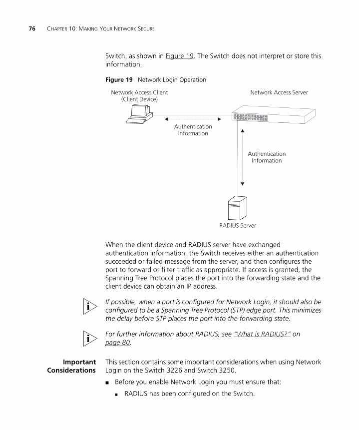
76 CHAPTER 10: MAKING YOUR NETWORK SECURE
Switch, as shown in Figure 19. The Switch does not interpret or store this information.
Figure 19 Network Login Operation
When the client device and RADIUS server have exchanged authentication information, the Switch receives either an authentication succeeded or failed message from the server, and then configures the port to forward or filter traffic as appropriate. If access is granted, the Spanning Tree Protocol places the port into the forwarding state and the client device can obtain an IP address.
If possible, when a port is configured for Network Login, it should also be configured to be a Spanning Tree Protocol (STP) edge port. This minimizes the delay before STP places the port into the forwarding state.
For further information about RADIUS, see “What is RADIUS?” on page 80.
ImportantConsiderations
This section contains some important considerations when using Network Login on the Switch 3226 and Switch 3250.
■ Before you enable Network Login you must ensure that:
■ RADIUS has been configured on the Switch.
Network Access ServerNetwork Access Client(Client Device)
AuthenticationInformation
AuthenticationInformation
RADIUS Server
What is Switch Management Login? 77
■ The RADIUS server in your network is operational.
■ If the RADIUS server fails or is unavailable, client devices will be unable to access the network.
■ Network Login is not supported on ports configured to operate as members of an aggregated link.
■ Some client devices that are connected to the Switch port may not support the authentication service, for example printers. You should configure the Switch port to operate in No Security mode then switch back to Static mode, so that network traffic that does not match the MAC address for the client device is filtered.
■ You should enable Network Login on all edge Switch ports. Failure to enable authentication on a single port could compromise the security of the entire network.
What is Switch Management Login?
If you intend to manage the Switch using the Web interface or the Command Line Interface, you need to log in with a valid user name and password.
For further information on managing the Switch, see the “Setting Up For Management” chapter in the Getting Started Guide.
The user name and password information can be stored in either:
■ a RADIUS server (recommended)
If you enable RADIUS as the authentication mode of Switch Management Login, the user name and password information is stored in a database on a RADIUS server in your network. Subsequent log in attempts to the Switch are remotely authenticated by the RADIUS server.
or
■ the local Switch database (default)
If you enable Local as the authentication mode of Switch Management Login, the user name and password information is stored in the local database on the Switch. Subsequent login attempts to the Switch are authenticated by the local database.
Benefits of RADIUSAuthentication
Day-to-day network maintenance can become a substantial overhead. For example, regularly changing the administrative password on a
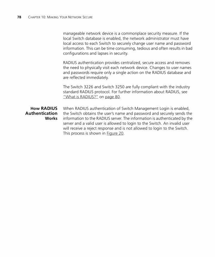
78 CHAPTER 10: MAKING YOUR NETWORK SECURE
manageable network device is a commonplace security measure. If the local Switch database is enabled, the network administrator must have local access to each Switch to securely change user name and password information. This can be time consuming, tedious and often results in bad configurations and lapses in security.
RADIUS authentication provides centralized, secure access and removes the need to physically visit each network device. Changes to user names and passwords require only a single action on the RADIUS database and are reflected immediately.
The Switch 3226 and Switch 3250 are fully compliant with the industry standard RADIUS protocol. For further information about RADIUS, see “What is RADIUS?” on page 80.
How RADIUSAuthentication
Works
When RADIUS authentication of Switch Management Login is enabled, the Switch obtains the user’s name and password and securely sends the information to the RADIUS server. The information is authenticated by the server and a valid user is allowed to login to the Switch. An invalid user will receive a reject response and is not allowed to login to the Switch. This process is shown in Figure 20.
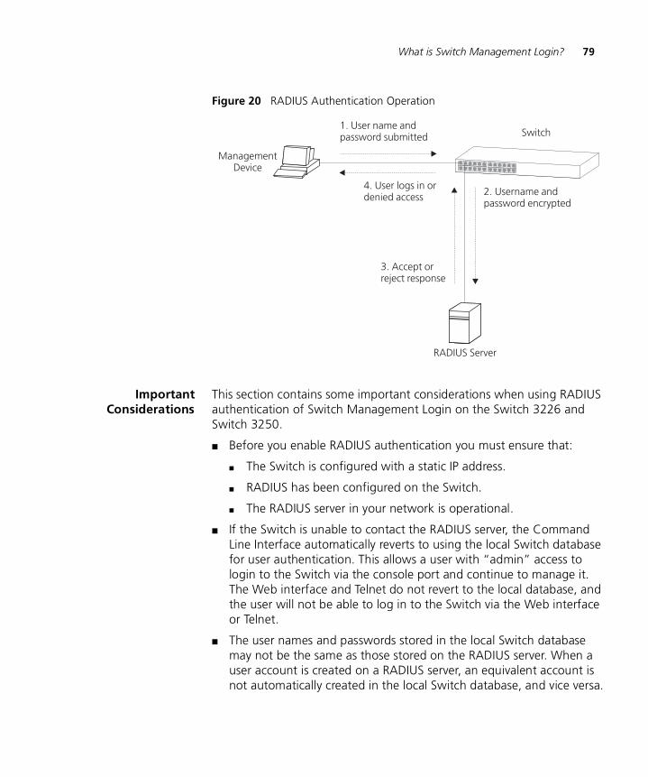
What is Switch Management Login? 79
Figure 20 RADIUS Authentication Operation
ImportantConsiderations
This section contains some important considerations when using RADIUS authentication of Switch Management Login on the Switch 3226 and Switch 3250.
■ Before you enable RADIUS authentication you must ensure that:
■ The Switch is configured with a static IP address.
■ RADIUS has been configured on the Switch.
■ The RADIUS server in your network is operational.
■ If the Switch is unable to contact the RADIUS server, the Command Line Interface automatically reverts to using the local Switch database for user authentication. This allows a user with “admin” access to login to the Switch via the console port and continue to manage it. The Web interface and Telnet do not revert to the local database, and the user will not be able to log in to the Switch via the Web interface or Telnet.
■ The user names and passwords stored in the local Switch database may not be the same as those stored on the RADIUS server. When a user account is created on a RADIUS server, an equivalent account is not automatically created in the local Switch database, and vice versa.
Switch
ManagementDevice
1. User name andpassword submitted
2. Username andpassword encrypted
RADIUS Server
3. Accept orreject response
4. User logs in ordenied access
80 CHAPTER 10: MAKING YOUR NETWORK SECURE
What is RADIUS? Remote Authentication Dial-In User Service (RADIUS) is an industry standard protocol for carrying authentication, authorization and configuration information between a network device and a shared authentication server. Transactions between each network device and the server are authenticated by the use of a shared secret. Additional security is provided by encryption of passwords to prevent interception by a network snooper.
RADIUS is defined in the RFCs 2865 and 2866, “Remote Authentication Dial-in User Service (RADIUS)” and “RADIUS Accounting”.
Network Login, a method of port-based access control, and Switch Management Login, used to control administrative access, both utilize the RADIUS protocol.
11
IP ROUTINGRouting is a method for distributing traffic throughout an IP network. It is used to join LANs at the network layer (Layer 3) of the Open Systems Interconnection (OSI) model. A router provides both filtering and bridging functions across the network.
This chapter explains routers, protocols, and how your Switch allows bridges and routers to interoperate. It covers the following topics:
■ What is Routing?
■ What is IP Routing?
■ Benefits of IP Routing
■ IP Routing Concepts
■ Multiple IP Interfaces per VLAN
■ Implementing IP Routing
■ IP Routing Protocols
■ User Datagram Protocol (UDP) Helper
■ Advanced IP Routing Options
For detailed information on setting up your Switch for management, see the Getting Started Guide that accompanies your Switch.
For detailed descriptions of the web interface operations and the command line interface (CLI) commands that you require to manage the Switch please refer to the Management Interface Reference Guide supplied in HTML format on the CD-ROM supplied with your Switch or on the 3Com Web site.
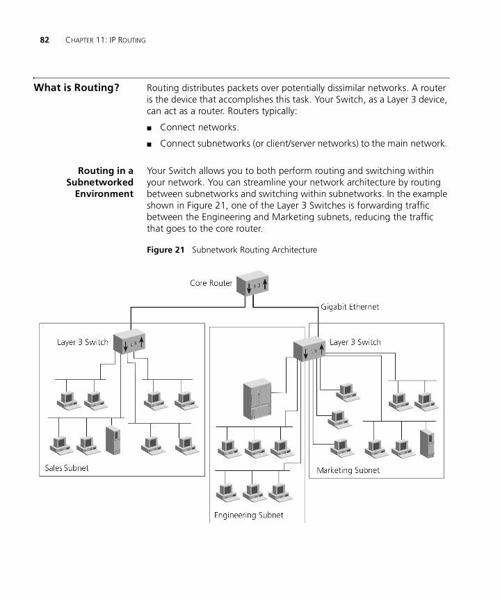
82 CHAPTER 11: IP ROUTING
What is Routing? Routing distributes packets over potentially dissimilar networks. A router is the device that accomplishes this task. Your Switch, as a Layer 3 device, can act as a router. Routers typically:
■ Connect networks.
■ Connect subnetworks (or client/server networks) to the main network.
Routing in aSubnetworked
Environment
Your Switch allows you to both perform routing and switching within your network. You can streamline your network architecture by routing between subnetworks and switching within subnetworks. In the example shown in Figure 21, one of the Layer 3 Switches is forwarding traffic between the Engineering and Marketing subnets, reducing the traffic that goes to the core router.
Figure 21 Subnetwork Routing Architecture
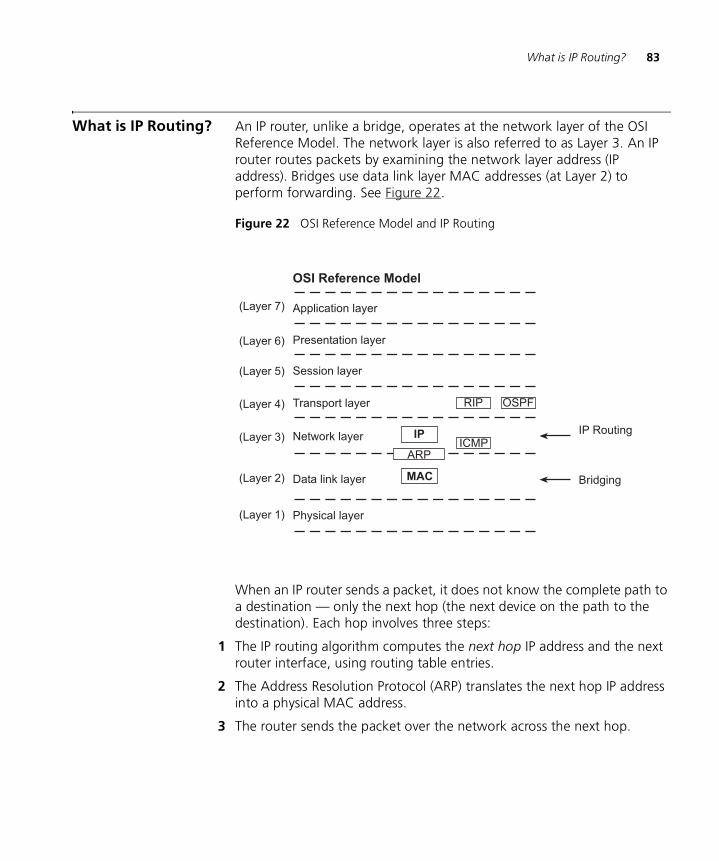
What is IP Routing? 83
What is IP Routing? An IP router, unlike a bridge, operates at the network layer of the OSI Reference Model. The network layer is also referred to as Layer 3. An IP router routes packets by examining the network layer address (IP address). Bridges use data link layer MAC addresses (at Layer 2) to perform forwarding. See Figure 22.
Figure 22 OSI Reference Model and IP Routing
When an IP router sends a packet, it does not know the complete path to a destination — only the next hop (the next device on the path to the destination). Each hop involves three steps:
1 The IP routing algorithm computes the next hop IP address and the next router interface, using routing table entries.
2 The Address Resolution Protocol (ARP) translates the next hop IP address into a physical MAC address.
3 The router sends the packet over the network across the next hop.
Application layer
Presentation layer
Session layer
Transport layer
Network layer
Data link layer
Physical layer
MAC
IP
OSI Reference Model
ARP
RIP
ICMP
OSPF
IP Routing
Bridging
84 CHAPTER 11: IP ROUTING
Benefits of IP Routing
IP routing provides the following features and benefits:
■ Economy — Because you can connect several segments to the same subnetwork with routing, you can increase the level of segmentation in your network without creating new subnetworks or assigning new network addresses. Instead, you can use additional Ethernet ports to expand existing subnetworks.
■ Optimal routing — IP routing can be the most powerful tool in a complex network setup for sending devices to find the best route to receiving devices. (The best route here is defined as the shortest and fastest route.)
■ Resiliency — If a router in the network goes down, the other routers update their routing tables to compensate for this occurrence; in a typical case, there is no need for you to manually intervene.
IP Routing Concepts IP routers use the following elements to transmit packets:
■ Router Interfaces
■ Routing Tables
■ Layer 3 Switching
■ Multiple IP Interfaces per VLAN
Router Interfaces A router interface connects the router to a subnetwork. On your Switch, more than one port can connect to the same subnetwork.
Each router interface has an IP address and a subnet mask. This router interface address defines both the number of the network to which the router interface is attached and its host number on that network. A router interface IP address serves three functions:
■ Sends IP packets to or from the router.
■ Defines the network and subnetwork numbers of the segment that is connected to that interface.
■ Provides access to the Switch using TCP/IP or to manage the Switch using the Simple Network Management Protocol (SNMP)
Figure 23 shows an example of a router interface configuration.
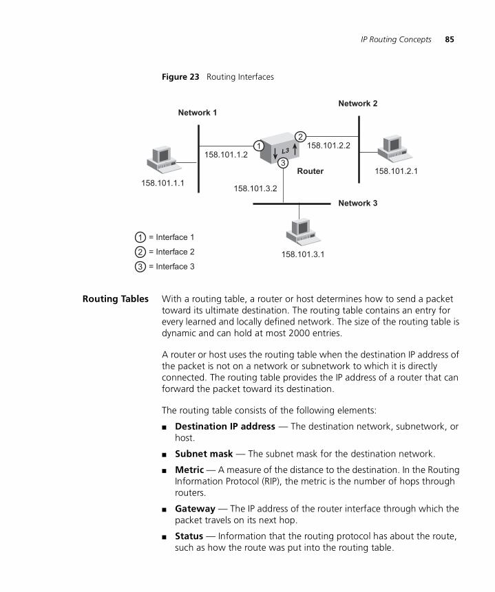
IP Routing Concepts 85
Figure 23 Routing Interfaces
Routing Tables With a routing table, a router or host determines how to send a packet toward its ultimate destination. The routing table contains an entry for every learned and locally defined network. The size of the routing table is dynamic and can hold at most 2000 entries.
A router or host uses the routing table when the destination IP address of the packet is not on a network or subnetwork to which it is directly connected. The routing table provides the IP address of a router that can forward the packet toward its destination.
The routing table consists of the following elements:
■ Destination IP address — The destination network, subnetwork, or host.
■ Subnet mask — The subnet mask for the destination network.
■ Metric — A measure of the distance to the destination. In the Routing Information Protocol (RIP), the metric is the number of hops through routers.
■ Gateway — The IP address of the router interface through which the packet travels on its next hop.
■ Status — Information that the routing protocol has about the route, such as how the route was put into the routing table.
L3158.101.1.2
Network 1
158.101.1.1
158.101.2.2
Network 2
158.101.3.2
Network 3
158.101.2.1
158.101.3.1
Router
12
3
= Interface 1
= Interface 2
= Interface 3
1
2
3
86 CHAPTER 11: IP ROUTING
Routing table data is updated statically or dynamically:
■ Statically — You manually enter static routes in the routing table. You can define up to 10 (maximum) static routes. Static routes are useful in environments where no routing protocol is used or where you want to override some of the routes that are generated with a routing protocol. Because static routes do not automatically change in response to network topology changes, manually configure only a small number of reasonably stable routes. Static routes do not time out, but they can be learned.
■ Dynamically — Routers use a protocol such as RIP or OSPF to automatically exchange routing data and to configure their routing tables dynamically. Routes are recalculated at regular intervals. This process helps you to keep up with network changes and allows the Switch to reconfigure routes quickly and reliably.
The Switch supports both RIPv1 and RIPv2.
Default Route
In addition to the routes to specific destinations, a routing table can contain a default route. The router uses the default route to forward packets that do not match any other routing table entry.
A default route is often used in place of static routes to numerous destinations that all have the same gateway IP address and interface number. The default route can be configured statically, or it can be learned dynamically.
A drawback to implementing a default static route is that it is a single point of failure on the network.
Layer 3 Switching Layer 3 switching is used to control how a bridge and a router interact within the same Switch. The Switch uses a routing over bridging scheme, first trying to determine if the packet will be switched or routed. The Switch does this by examining the destination MAC address:
■ If the destination MAC address is the internal router port on this Switch, the packet is routed (Layer 3).
■ If the destination MAC address is not one of the router interfaces MAC addresses on this Switch, then the packet will be switched and is forwarded according to the IEEE 802.1D protocol.
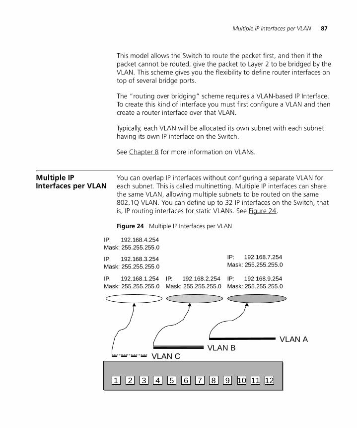
Multiple IP Interfaces per VLAN 87
This model allows the Switch to route the packet first, and then if the packet cannot be routed, give the packet to Layer 2 to be bridged by the VLAN. This scheme gives you the flexibility to define router interfaces on top of several bridge ports.
The “routing over bridging” scheme requires a VLAN-based IP Interface. To create this kind of interface you must first configure a VLAN and then create a router interface over that VLAN.
Typically, each VLAN will be allocated its own subnet with each subnet having its own IP interface on the Switch.
See Chapter 8 for more information on VLANs.
Multiple IP Interfaces per VLAN
You can overlap IP interfaces without configuring a separate VLAN for each subnet. This is called multinetting. Multiple IP interfaces can share the same VLAN, allowing multiple subnets to be routed on the same 802.1Q VLAN. You can define up to 32 IP interfaces on the Switch, that is, IP routing interfaces for static VLANs. See Figure 24.
Figure 24 Multiple IP Interfaces per VLAN
1 2 3 4 5 6 7 8 9 10 11 12
VLAN AVLAN B
VLAN C
IP: 192.168.1.254Mask: 255.255.255.0
IP: 192.168.2.254Mask: 255.255.255.0
IP: 192.168.9.254Mask: 255.255.255.0
IP: 192.168.3.254Mask: 255.255.255.0
IP: 192.168.4.254Mask: 255.255.255.0
IP: 192.168.7.254Mask: 255.255.255.0
88 CHAPTER 11: IP ROUTING
Implementing IP Routing
To route network traffic using IP, you must perform these tasks in the following order:
1 Configure VLANs.
2 Establish IP nterfaces on those VLANS.
Configuring IP VLANs If you want to use IP routing, you must first configure the VLAN to use IP. You can create network-based VLANs that are grouped according to the IP network address and mask.
See Chapter 8 for more information on VLANs.
Establishing IPInterfaces
To establish an IP interface:
1 Determine your interface parameters.
2 Define the IP interfaces.
Interface Parameters
Each IP routing interface has these standard characteristics:
■ IP address — An address from the range of addresses that the Internet Engineering Task Force (IETF) assigns to your organization. This address is specific to your network and Switch. Refer to Appendix C for details on IP Addressing.
■ Subnet mask — The 32-bit number that uses the same format and representation as an IP address. The subnet mask determines which bits in the IP address are interpreted as the network number/subnetwork number and the host number. Each IP address bit that corresponds to a 1 in the subnet mask is in the network/subnetwork part of the address. Each IP address bit that corresponds to a 0 is in the host part of the IP address.
■ State — The status of the IP interface. It indicates whether the interface is available for communications (Up) or unavailable (Down). This is not a user configurable parameter.
■ VLAN interface index — The number of the VLAN that is associated with the IP interface. When the Switch prompts you for this option, the menu identifies the available VLAN indexes.
Implementing IP Routing 89
Defining an IP Interface
After you decide the VLAN index, IP address, and subnet mask for each IP interface you want to create, you can define each interface using the Command Line Interface or the Web interface.
Before you assign IP addresses, map out the entire network and subnetwork IP addressing scheme. Plan for future expansion of address numbers as well.
Remember that you must define a VLAN before you define the IP (routing) interface. See Chapter 8 for more information on VLANs.
You Switch provides the following advanced IP features:
■ Routing Information Protocol (RIP)
■ User Datagram Protocol (UDP) Helper
■ ARP Proxy
■ Internet Control Message Protocol (ICMP)
These features are discussed later in this chapter.
You can use the Routing Information Protocol (RIP) protocol to take advantage of routing capabilities. RIP is discussed in this chapter.
Administering IP Routing
Keep these points in mind while you administer the IP network:
■ Flush the ARP cache regularly if you set the age time to 0.
■ Set up a default route.
The Switch uses the default route to forward packets that do not match any other routing table entry. You may want to use the default route in place of routes to numerous destinations that all have the same gateway IP address. If you do not use a default route, ICMP is more likely to return an ICMP Network Unreachable error.
■ Before you can define static routes, you must define at least one IP interface. See “Defining an IP Interface” on page 89 for more information. Remember the following guidelines:
■ Static routes remain in the routing table until you remove them or the corresponding interface.
■ Static routes are removed during a system initialize.
90 CHAPTER 11: IP ROUTING
■ Static routes take precedence over dynamically learned routes to the same destination.
■ Static routes are included in periodic RIP updates sent by your Layer 3 Switch.
IP Routing Protocols IP protocols are a set of uniquely defined interactions that allow data communications to occur. Protocols are the rules to which networks must adhere in order to successfully operate. Protocols that are discussed in this section include:
■ Routing Information Protocol (RIP)
■ User Datagram Protocol (UDP) Helper
■ Address Resolution Protocol (ARP)
■ Internet Control Message Protocol (ICMP)
Routing InformationProtocol (RIP)
RIP is the protocol that implements routing. RIP does this by using Distance Vector Algorithms (DVAs) to calculate the route with the fewest number of hops to the destination of a route request. Each device keeps its own set of routes in its routing table. RIP is an Interior Gateway Protocol (IGP) for TCP/IP networks.
RIP operates using both active and passive devices.
■ Active devices, usually routers, broadcast RIP messages to all devices in a network or subnetwork and update their internal routing tables when they receive a RIP message.
■ Passive devices, usually hosts, listen for RIP messages and update their internal routing tables, but do not send RIP messages.
An active router sends a broadcast RIP message every 30 seconds. This message contains the IP address and a metric (distance) from the router to each destination in the routing table. In RIP, each router through which a packet must travel to reach a destination counts as one network hop.
Basic RIP Parameters
There are several parameters to consider when you set up RIP for your network. When you configure an IP interface, the Switch already has the RIP parameters set to the defaults listed in Table 6.
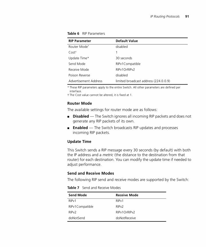
IP Routing Protocols 91
Router Mode
The available settings for router mode are as follows:
■ Disabled — The Switch ignores all incoming RIP packets and does not generate any RIP packets of its own.
■ Enabled — The Switch broadcasts RIP updates and processes incoming RIP packets.
Update Time
This Switch sends a RIP message every 30 seconds (by default) with both the IP address and a metric (the distance to the destination from that router) for each destination. You can modify the update time if needed to adjust performance.
Send and Receive Modes
The following RIP send and receive modes are supported by the Switch:
Table 6 RIP Parameters
RIP Parameter Default Value
Router Mode*
* These RIP parameters apply to the entire Switch. All other parameters are defined per interface.
disabled
Cost†
† The Cost value cannot be altered, it is fixed at 1.
1
Update Time* 30 seconds
Send Mode RIPv1Compatible
Receive Mode RIPv1OrRIPv2
Poison Reverse disabled
Advertisement Address limited broadcast address (224.0.0.9)
Table 7 Send and Receive Modes
Send Mode Receive Mode
RIPv1 RIPv1
RIPv1Compatible RIPv2
RIPv2 RIPv1OrRIPv2
doNotSend doNotReceive
92 CHAPTER 11: IP ROUTING
■ RIPv1 – Route information is broadcast periodically to other routers on the network using the advertisement list for RIP-1 updates.
■ RIPv2 – Route information is multicast periodically to other routers on the network using the multicast address of 224.0.0.9. This method reduces the load on hosts that are not configured to listen to RIP-2 messages.
■ RIPv1 Compatible – Route information is broadcast to other routers on the network using the advertisement list for RIP-2 updates.
■ RIPv1OrRIPv2 – Both RIP-1 and RIP-2 route information can be received by the Switch.
■ doNotSend – The Switch will not broadcast (or advertise) RIP updates.
■ doNotReceive – The Switch does not process (or passively learn) incoming RIP packets.
The doNotSend and doNotReceive modes are also referred to as one-way learn and advertise modes.
Poison Reverse
Poison Reverse is a RIP feature that you use specifically with a scheme called Split Horizon. The Switch disables Poison Reverse by default.
Split Horizon avoids the problems that reverse-route updates can cause. Reverse-route updates are sent to a neighboring router and include the routes that are learned from that router. Split Horizon omits the routes that are learned from one neighbor in the updates that are sent to that neighbor (the reverse routes).
Poison Reverse is essentially another layer of protection against advertising reverse routes.
■ When you enable Poison Reverse, the Switch advertises reverse routes in updates, but it sets the metrics to 16 (infinity). Setting the metric to infinity breaks the loop immediately when two routers have routes that point to each other.
■ When you disable (default mode) Poison Reverse, such reverse routes are not advertised.
You can disable Poison Reverse because it augments what Split Horizon already does, and it puts additional information that you may not need into RIP updates.
IP Routing Protocols 93
Advertisement Address
The Switch uses the advertisement address to advertise routes to other stations on the same network. Each interface that you define uses a directed broadcast address as the advertisement address. The Switch uses this address for sending updates.
RIP-1 Versus RIP-2
Like RIP-1, RIP-2 allows the Switch to dynamically configure its own routing table. RIP-2 is much more flexible and efficient than RIP-1, however, because RIP-2 advertises using the multicast method, which can advertise to a subset of the network (RIP-1 uses the broadcast method, which advertises to the whole network). RIP-2 can do this because it includes a subnet mask in its header.
If your Switch receives a RIP-2 packet, it puts the route into the routing table with the subnet mask that was advertised.
Important Considerations
Note the following considerations when you implement RIP on your Switch:
■ Use RIP-2 rather than RIP-1 if possible, because RIP-2 uses subnet masking and the next hop field. Subnet mask advertising allows you to use VLSM (Variable Length Subnet Mask).
■ Where possible, set RIP as follows:
■ Send Mode — RIPv2
■ Receive Mode — RIPv1OrRIPv2
In this way, the Switch keeps track of the RIP-1 and RIP-2 address routes in its routing table and forwards the routes as well.
■ When using Spanning Tree (STP), Rapid Spanning Tree (RSTP) and Routing Information Protocol (RIP) all Switches must communicate with each other on the same VLAN.
User DatagramProtocol (UDP) Helper
User Datagram Protocol (UDP) Helper allows TCP/IP applications to forward broadcast packets from one part of the network to another. The most common uses of UDP are:
■ Bootstrap Protocol (BOOTP)
BOOTP allows you to boot a host through the router using a logical port. This can be done even when the host is on another part of the
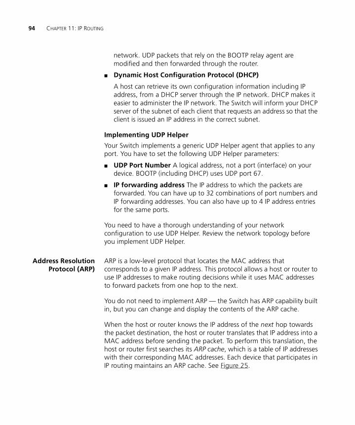
94 CHAPTER 11: IP ROUTING
network. UDP packets that rely on the BOOTP relay agent are modified and then forwarded through the router.
■ Dynamic Host Configuration Protocol (DHCP)
A host can retrieve its own configuration information including IP address, from a DHCP server through the IP network. DHCP makes it easier to administer the IP network. The Switch will inform your DHCP server of the subnet of each client that requests an address so that the client is issued an IP address in the correct subnet.
Implementing UDP Helper
Your Switch implements a generic UDP Helper agent that applies to any port. You have to set the following UDP Helper parameters:
■ UDP Port Number A logical address, not a port (interface) on your device. BOOTP (including DHCP) uses UDP port 67.
■ IP forwarding address The IP address to which the packets are forwarded. You can have up to 32 combinations of port numbers and IP forwarding addresses. You can also have up to 4 IP address entries for the same ports.
You need to have a thorough understanding of your network configuration to use UDP Helper. Review the network topology before you implement UDP Helper.
Address ResolutionProtocol (ARP)
ARP is a low-level protocol that locates the MAC address that corresponds to a given IP address. This protocol allows a host or router to use IP addresses to make routing decisions while it uses MAC addresses to forward packets from one hop to the next.
You do not need to implement ARP — the Switch has ARP capability built in, but you can change and display the contents of the ARP cache.
When the host or router knows the IP address of the next hop towards the packet destination, the host or router translates that IP address into a MAC address before sending the packet. To perform this translation, the host or router first searches its ARP cache, which is a table of IP addresses with their corresponding MAC addresses. Each device that participates in IP routing maintains an ARP cache. See Figure 25.
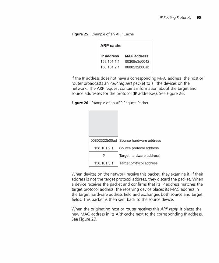
IP Routing Protocols 95
Figure 25 Example of an ARP Cache
If the IP address does not have a corresponding MAC address, the host or router broadcasts an ARP request packet to all the devices on the network. The ARP request contains information about the target and source addresses for the protocol (IP addresses). See Figure 26.
Figure 26 Example of an ARP Request Packet
When devices on the network receive this packet, they examine it. If their address is not the target protocol address, they discard the packet. When a device receives the packet and confirms that its IP address matches the target protocol address, the receiving device places its MAC address in the target hardware address field and exchanges both source and target fields. This packet is then sent back to the source device.
When the originating host or router receives this ARP reply, it places the new MAC address in its ARP cache next to the corresponding IP address. See Figure 27.
ARP cache
158.101.1.1
158.101.2.1
IP address MAC address
00308e3d0042
0080232b00ab
158.101.3.1
158.101.2.1
Source hardware address
?
Source protocol address
Target protocol address
Target hardware address
00802322b00ad
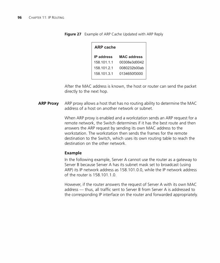
96 CHAPTER 11: IP ROUTING
Figure 27 Example of ARP Cache Updated with ARP Reply
After the MAC address is known, the host or router can send the packet directly to the next hop.
ARP Proxy ARP proxy allows a host that has no routing ability to determine the MAC address of a host on another network or subnet.
When ARP proxy is enabled and a workstation sends an ARP request for a remote network, the Switch determines if it has the best route and then answers the ARP request by sending its own MAC address to the workstation. The workstation then sends the frames for the remote destination to the Switch, which uses its own routing table to reach the destination on the other network.
Example
In the following example, Server A cannot use the router as a gateway to Server B because Server A has its subnet mask set to broadcast (using ARP) its IP network address as 158.101.0.0, while the IP network address of the router is 158.101.1.0.
However, if the router answers the request of Server A with its own MAC address — thus, all traffic sent to Server B from Server A is addressed to the corresponding IP interface on the router and forwarded appropriately.
ARP cache
158.101.1.1
158.101.2.1
158.101.3.1
IP address MAC address
00308e3d0042
0080232b00ab
0134650f3000
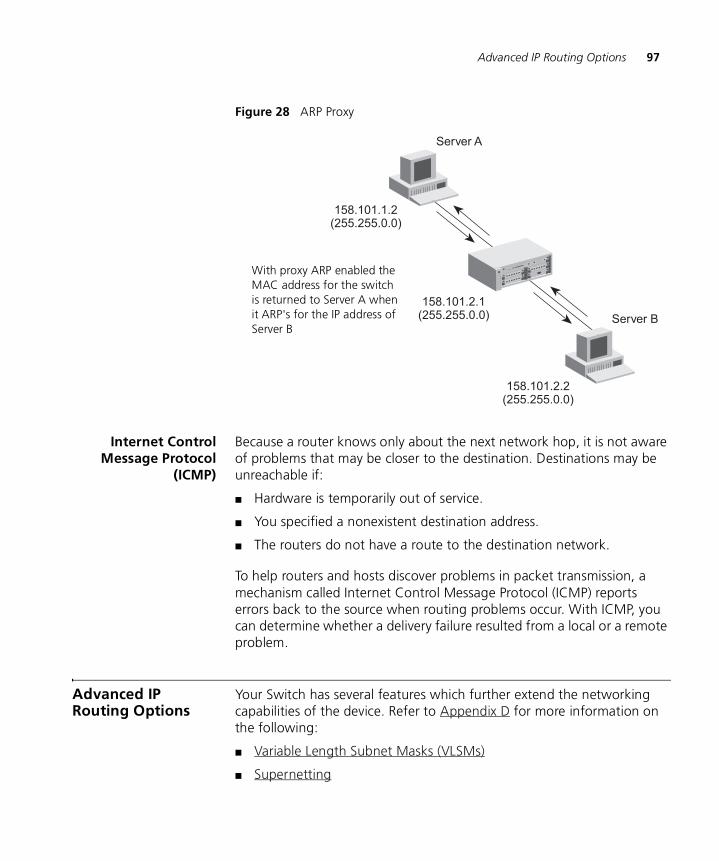
Advanced IP Routing Options 97
Figure 28 ARP Proxy
Internet ControlMessage Protocol
(ICMP)
Because a router knows only about the next network hop, it is not aware of problems that may be closer to the destination. Destinations may be unreachable if:
■ Hardware is temporarily out of service.
■ You specified a nonexistent destination address.
■ The routers do not have a route to the destination network.
To help routers and hosts discover problems in packet transmission, a mechanism called Internet Control Message Protocol (ICMP) reports errors back to the source when routing problems occur. With ICMP, you can determine whether a delivery failure resulted from a local or a remote problem.
Advanced IP Routing Options
Your Switch has several features which further extend the networking capabilities of the device. Refer to Appendix D for more information on the following:
■ Variable Length Subnet Masks (VLSMs)
■ Supernetting
Server A
Server B
158.101.1.2(255.255.0.0)
158.101.2.1(255.255.0.0)
158.101.2.2(255.255.0.0)
With Proxy ARP enabledthe MAC address of Server Bis returned to Server A becausethe subnetworks are transparent
With proxy ARP enabled the MAC address for the switch is returned to Server A when it ARP's for the IP address of Server B

98 CHAPTER 11: IP ROUTING
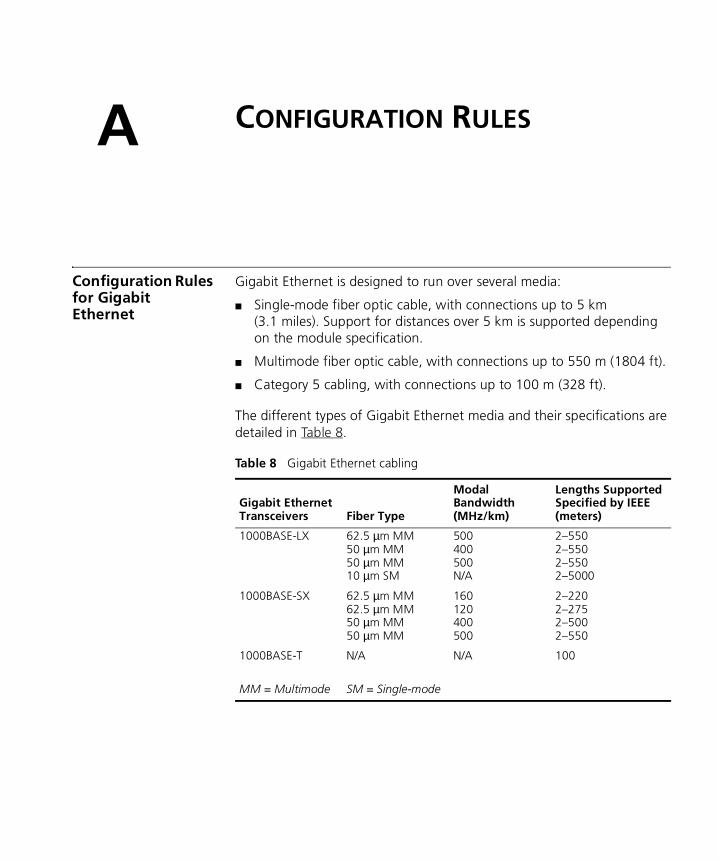
A
CONFIGURATION RULESConfiguration Rules for Gigabit Ethernet
Gigabit Ethernet is designed to run over several media:
■ Single-mode fiber optic cable, with connections up to 5 km (3.1 miles). Support for distances over 5 km is supported depending on the module specification.
■ Multimode fiber optic cable, with connections up to 550 m (1804 ft).
■ Category 5 cabling, with connections up to 100 m (328 ft).
The different types of Gigabit Ethernet media and their specifications are detailed in Table 8.
Table 8 Gigabit Ethernet cabling
Gigabit EthernetTransceivers Fiber Type
Modal Bandwidth(MHz/km)
Lengths SupportedSpecified by IEEE(meters)
1000BASE-LX
1000BASE-SX
1000BASE-T
MM = Multimode
62.5 µm MM50 µm MM50 µm MM10 µm SM
62.5 µm MM62.5 µm MM50 µm MM50 µm MM
N/A
SM = Single-mode
500400500N/A
160120400500
N/A
2–5502–5502–5502–5000
2–2202–2752–5002–550
100
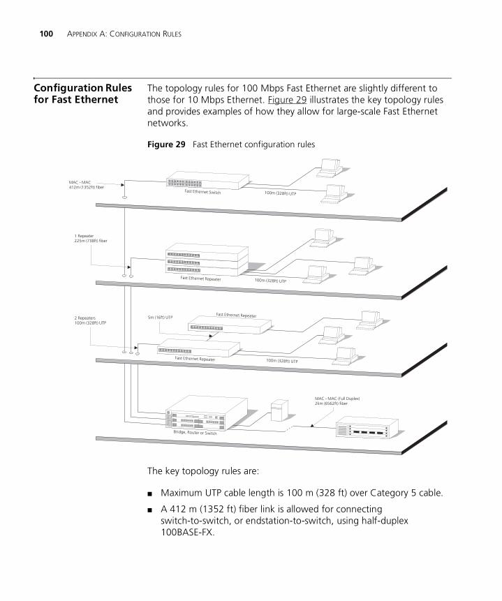
100 APPENDIX A: CONFIGURATION RULES
Configuration Rules for Fast Ethernet
The topology rules for 100 Mbps Fast Ethernet are slightly different to those for 10 Mbps Ethernet. Figure 29 illustrates the key topology rules and provides examples of how they allow for large-scale Fast Ethernet networks.
Figure 29 Fast Ethernet configuration rules
The key topology rules are:
■ Maximum UTP cable length is 100 m (328 ft) over Category 5 cable.
■ A 412 m (1352 ft) fiber link is allowed for connecting switch-to-switch, or endstation-to-switch, using half-duplex 100BASE-FX.
Configuration Rules for Fast Ethernet 101
■ A total network span of 325 m (1066 ft) is allowed in single-repeater topologies (one hub stack per wiring closet with a fiber link to the collapsed backbone). For example, a 225 m (738 ft) fiber link from a repeater to a router or switch, plus a 100 m (328 ft) UTP link from a repeater out to the endstations.
Configuration Ruleswith Full Duplex
The Switch provides full duplex support for all its ports, excluding ports operating at Gigabit speeds. Full duplex allows packets to be transmitted and received simultaneously and, in effect, doubles the potential throughput of a link.
With full duplex, the Ethernet topology rules are the same, but the Fast Ethernet rules are:
■ Maximum UTP cable length is 100 m (328 ft) over Category 5 cable.
■ A 2 km (6562 ft) fiber link is allowed for connecting switch-to-switch, or endstation-to-switch.

102 APPENDIX A: CONFIGURATION RULES
B
NETWORK CONFIGURATION EXAMPLESThis chapter contains the following sections:
■ Simple Network Configuration Example
■ Desktop Switch Example
■ Advanced Network Configuration Example
■ Edge Switch Example

104 APPENDIX B: NETWORK CONFIGURATION EXAMPLES
Simple Network Configuration Example
The following illustration shows how the Switch 3226 and Switch 3250 can be used in your network.
Desktop SwitchExample
The example in Figure 30 shows how a Switch 3226 can be used for a group of users that require dedicated 10 Mbps or 100 Mbps connections to the desktop. It illustrates the use of VLANs to separate an area of the network and the use of an aggregated link to increase the bandwidth on key links in your network.
Figure 30 Using the Switch 3226 and Switch 3250 in a desktop environment
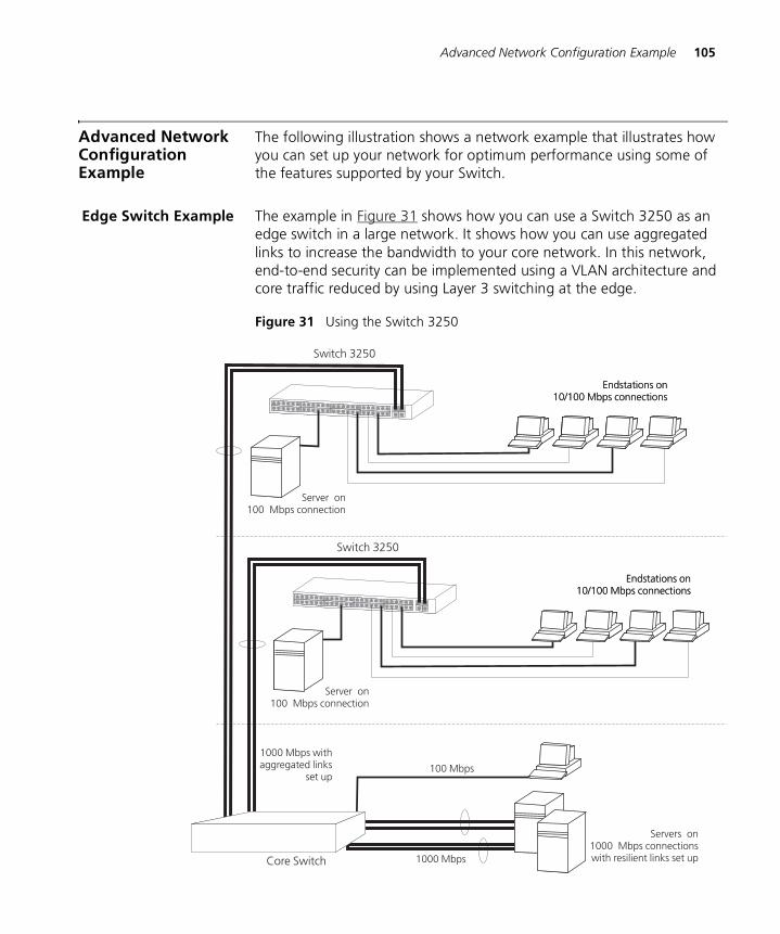
Advanced Network Configuration Example 105
Advanced Network Configuration Example
The following illustration shows a network example that illustrates how you can set up your network for optimum performance using some of the features supported by your Switch.
Edge Switch Example The example in Figure 31 shows how you can use a Switch 3250 as an edge switch in a large network. It shows how you can use aggregated links to increase the bandwidth to your core network. In this network, end-to-end security can be implemented using a VLAN architecture and core traffic reduced by using Layer 3 switching at the edge.
Figure 31 Using the Switch 3250

106 APPENDIX B: NETWORK CONFIGURATION EXAMPLES
C
IP ADDRESSINGThis chapter provides some background detail on the IP information that needs to be assigned to your Switch to enable you to manage it across a network. The topics covered are:
■ IP Addresses
■ Subnets and Subnet Masks
■ Default Gateways
IP addressing is a vast topic and there are white papers on the World Wide Web and publications available if you wish to learn more about IP addressing.
IP Addresses This IP address section is divided into two parts:
■ Simple Overview — Gives a brief overview of what an IP address is.
■ Advanced Overview — Gives a more in depth explanation of IP addresses and the way they are structured.
Simple Overview To operate correctly, each device on your network must have a unique IP address. IP addresses have the format n.n.n.n where n is a decimal number between 0 and 255. An example IP address is ‘192.168.100.8’.
The IP address can be split into two parts:
■ The first part, called the network part, (‘192.168’ in the example) identifies the network on which the device resides.
■ The second part, called the host part, (‘100.8’ in the example) identifies the device within the network.
If your network is internal to your organization only, you may use any arbitrary IP address. 3Com suggests you use addresses in the series
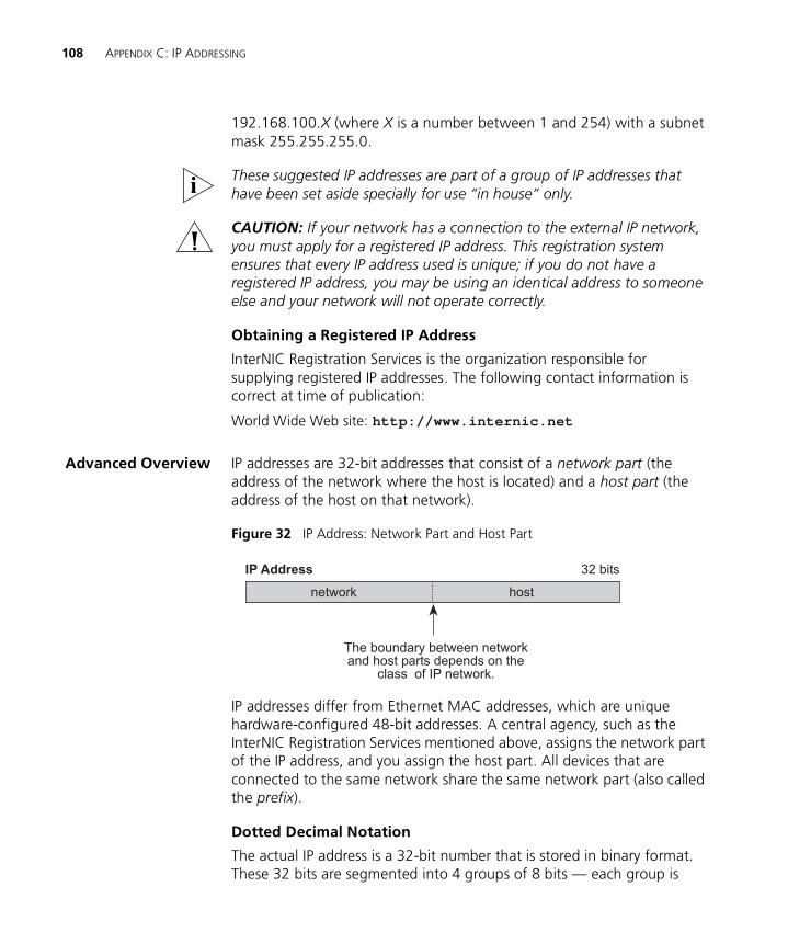
108 APPENDIX C: IP ADDRESSING
192.168.100.X (where X is a number between 1 and 254) with a subnet mask 255.255.255.0.
These suggested IP addresses are part of a group of IP addresses that have been set aside specially for use “in house” only.
CAUTION: If your network has a connection to the external IP network, you must apply for a registered IP address. This registration system ensures that every IP address used is unique; if you do not have a registered IP address, you may be using an identical address to someone else and your network will not operate correctly.
Obtaining a Registered IP Address
InterNIC Registration Services is the organization responsible for supplying registered IP addresses. The following contact information is correct at time of publication:
World Wide Web site: http://www.internic.net
Advanced Overview IP addresses are 32-bit addresses that consist of a network part (the address of the network where the host is located) and a host part (the address of the host on that network).
Figure 32 IP Address: Network Part and Host Part
IP addresses differ from Ethernet MAC addresses, which are unique hardware-configured 48-bit addresses. A central agency, such as the InterNIC Registration Services mentioned above, assigns the network part of the IP address, and you assign the host part. All devices that are connected to the same network share the same network part (also called the prefix).
Dotted Decimal Notation
The actual IP address is a 32-bit number that is stored in binary format. These 32 bits are segmented into 4 groups of 8 bits — each group is
IP Address
network host
32 bits
The boundary between networkand host parts depends on the
class of IP network.
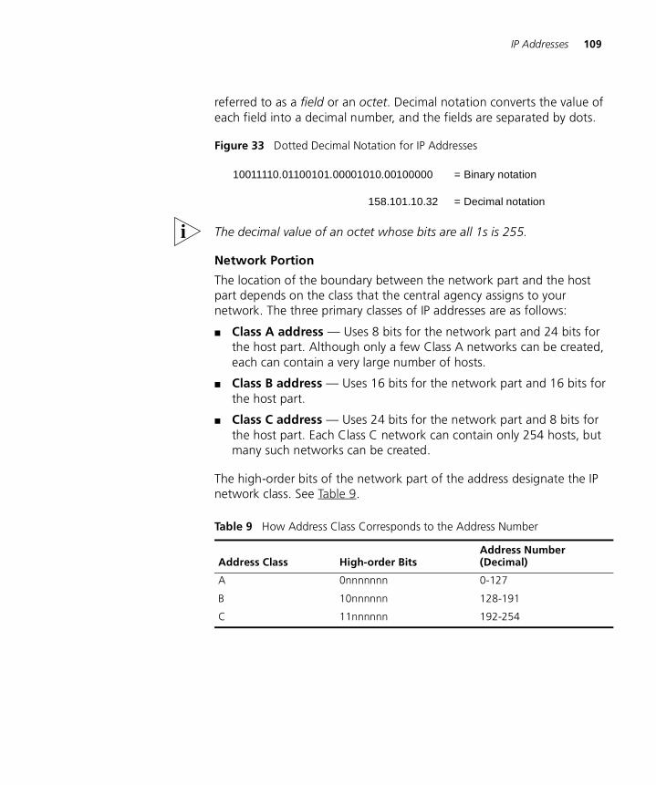
IP Addresses 109
referred to as a field or an octet. Decimal notation converts the value of each field into a decimal number, and the fields are separated by dots.
Figure 33 Dotted Decimal Notation for IP Addresses
The decimal value of an octet whose bits are all 1s is 255.
Network Portion
The location of the boundary between the network part and the host part depends on the class that the central agency assigns to your network. The three primary classes of IP addresses are as follows:
■ Class A address — Uses 8 bits for the network part and 24 bits for the host part. Although only a few Class A networks can be created, each can contain a very large number of hosts.
■ Class B address — Uses 16 bits for the network part and 16 bits for the host part.
■ Class C address — Uses 24 bits for the network part and 8 bits for the host part. Each Class C network can contain only 254 hosts, but many such networks can be created.
The high-order bits of the network part of the address designate the IP network class. See Table 9.
Table 9 How Address Class Corresponds to the Address Number
Address Class High-order BitsAddress Number (Decimal)
A 0nnnnnnn 0-127
B 10nnnnnn 128-191
C 11nnnnnn 192-254
158.101.10.32
10011110.01100101.00001010.00100000 = Binary notation
= Decimal notation
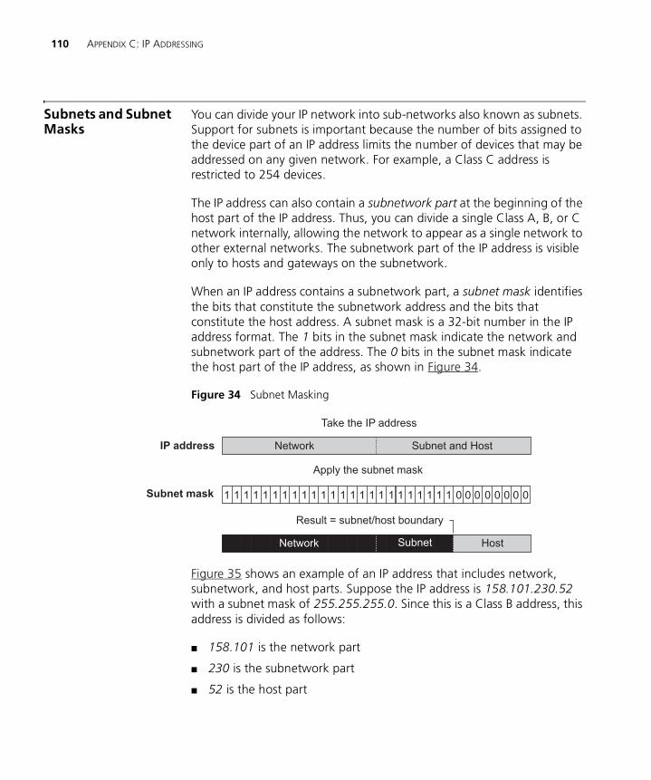
110 APPENDIX C: IP ADDRESSING
Subnets and Subnet Masks
You can divide your IP network into sub-networks also known as subnets. Support for subnets is important because the number of bits assigned to the device part of an IP address limits the number of devices that may be addressed on any given network. For example, a Class C address is restricted to 254 devices.
The IP address can also contain a subnetwork part at the beginning of the host part of the IP address. Thus, you can divide a single Class A, B, or C network internally, allowing the network to appear as a single network to other external networks. The subnetwork part of the IP address is visible only to hosts and gateways on the subnetwork.
When an IP address contains a subnetwork part, a subnet mask identifies the bits that constitute the subnetwork address and the bits that constitute the host address. A subnet mask is a 32-bit number in the IP address format. The 1 bits in the subnet mask indicate the network and subnetwork part of the address. The 0 bits in the subnet mask indicate the host part of the IP address, as shown in Figure 34.
Figure 34 Subnet Masking
Figure 35 shows an example of an IP address that includes network, subnetwork, and host parts. Suppose the IP address is 158.101.230.52 with a subnet mask of 255.255.255.0. Since this is a Class B address, this address is divided as follows:
■ 158.101 is the network part
■ 230 is the subnetwork part
■ 52 is the host part
IP address Network Subnet and Host
Subnet mask
networ HostsubnSubnetNetwork
Apply the subnet mask
Result = subnet/host boundary
Take the IP address
1 01 1 1 1 1 1 1 1 1 1 00000001 1 1 1 1 1 1 1 1 1 1 1 1
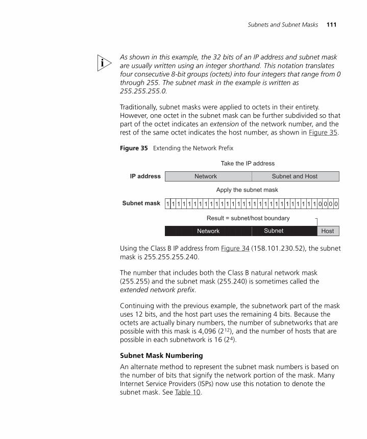
Subnets and Subnet Masks 111
As shown in this example, the 32 bits of an IP address and subnet mask are usually written using an integer shorthand. This notation translates four consecutive 8-bit groups (octets) into four integers that range from 0 through 255. The subnet mask in the example is written as 255.255.255.0.
Traditionally, subnet masks were applied to octets in their entirety. However, one octet in the subnet mask can be further subdivided so that part of the octet indicates an extension of the network number, and the rest of the same octet indicates the host number, as shown in Figure 35.
Figure 35 Extending the Network Prefix
Using the Class B IP address from Figure 34 (158.101.230.52), the subnet mask is 255.255.255.240.
The number that includes both the Class B natural network mask (255.255) and the subnet mask (255.240) is sometimes called the extended network prefix.
Continuing with the previous example, the subnetwork part of the mask uses 12 bits, and the host part uses the remaining 4 bits. Because the octets are actually binary numbers, the number of subnetworks that are possible with this mask is 4,096 (212), and the number of hosts that are possible in each subnetwork is 16 (24).
Subnet Mask Numbering
An alternate method to represent the subnet mask numbers is based on the number of bits that signify the network portion of the mask. Many Internet Service Providers (ISPs) now use this notation to denote the subnet mask. See Table 10.
IP address Network Subnet and Host
Subnet mask
networ HostsubnSubnetNetwork
Apply the subnet mask
Result = subnet/host boundary
Take the IP address
1 01 1 1 1 1 1 1 1 1 1 0001 1 1 1 1 1 1 1 1 1 1 1 1 1 1 1 1
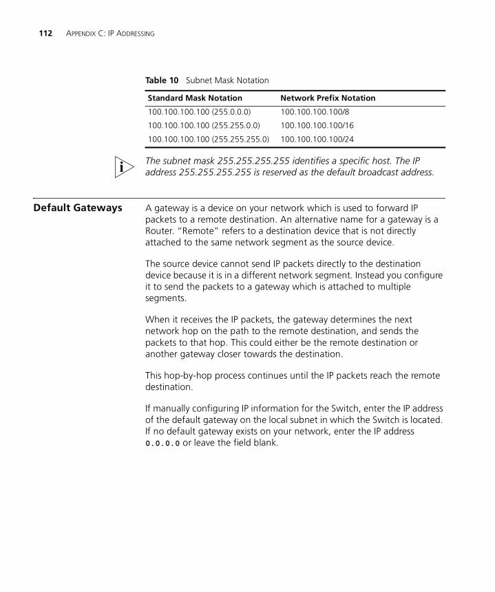
112 APPENDIX C: IP ADDRESSING
The subnet mask 255.255.255.255 identifies a specific host. The IP address 255.255.255.255 is reserved as the default broadcast address.
Default Gateways A gateway is a device on your network which is used to forward IP packets to a remote destination. An alternative name for a gateway is a Router. “Remote” refers to a destination device that is not directly attached to the same network segment as the source device.
The source device cannot send IP packets directly to the destination device because it is in a different network segment. Instead you configure it to send the packets to a gateway which is attached to multiple segments.
When it receives the IP packets, the gateway determines the next network hop on the path to the remote destination, and sends the packets to that hop. This could either be the remote destination or another gateway closer towards the destination.
This hop-by-hop process continues until the IP packets reach the remote destination.
If manually configuring IP information for the Switch, enter the IP address of the default gateway on the local subnet in which the Switch is located. If no default gateway exists on your network, enter the IP address 0.0.0.0 or leave the field blank.
Table 10 Subnet Mask Notation
Standard Mask Notation Network Prefix Notation
100.100.100.100 (255.0.0.0) 100.100.100.100/8
100.100.100.100 (255.255.0.0) 100.100.100.100/16
100.100.100.100 (255.255.255.0) 100.100.100.100/24
D
ADVANCED IP ROUTING CONCEPTSThis chapter provides some additional background detail on the IP information that can be assigned to your Switch to enable you to manage it across a network. These are advanced features and are not required for operating your switch in your network. The topics covered are:
■ Variable Length Subnet Masks (VLSMs)
■ Supernetting
Variable Length Subnet Masks (VLSMs)
With Variable Length Subnet Masks (VLSMs), each subnetwork under a network can use its own subnet mask. Therefore, with VLSM, you can get more subnetwork space out of your assigned IP address space.
How VLSMs Work
VLSMs get beyond the restriction that a single subnet mask imposes on the network. One subnet mask per IP network address fixes the number of subnetworks and the number of hosts per subnetwork.
For example, if you decide to configure the 158.100.0.0/16 network with a /23 extended-network prefix, you can create 128 subnetworks with each having up to 510 hosts. If some of the subnetworks do not need that many hosts, you would assign many host IP addresses but not use them.
With VLSMs, you can assign another subnet mask, for instance, /27, to the same IP address. So you can assign a longer subnet mask that consequently uses fewer host IP addresses. As a result, routing tables are smaller and more efficient.
This method of further subdividing addresses using VLSMs is being used increasingly more as networks grow in size and number. However, be aware that this method of addressing can greatly increase your network
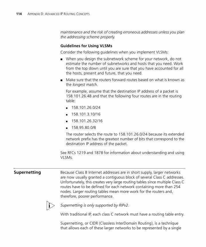
114 APPENDIX D: ADVANCED IP ROUTING CONCEPTS
maintenance and the risk of creating erroneous addresses unless you plan the addressing scheme properly.
Guidelines for Using VLSMs
Consider the following guidelines when you implement VLSMs:
■ When you design the subnetwork scheme for your network, do not estimate the number of subnetworks and hosts that you need. Work from the top down until you are sure that you have accounted for all the hosts, present and future, that you need.
■ Make sure that the routers forward routes based on what is known as the longest match.
For example, assume that the destination IP address of a packet is 158.101.26.48 and that the following four routes are in the routing table:
■ 158.101.26.0/24
■ 158.101.3.10/16
■ 158.101.26.32/16
■ 158.95.80.0/8
The router selects the route to 158.101.26.0/24 because its extended network prefix has the greatest number of bits that correspond to the destination IP address of the packet.
See RFCs 1219 and 1878 for information about understanding and using VLSMs.
Supernetting Because Class B Internet addresses are in short supply, larger networks are now usually granted a contiguous block of several Class C addresses. Unfortunately, this creates very large routing tables since multiple Class C routes have to be defined for each network containing more than 254 nodes. Larger routing tables mean more work for the routers and, therefore, poorer performance.
Supernetting is only supported by RIPv2.
With traditional IP, each class C network must have a routing table entry.
Supernetting, or CIDR (Classless InterDomain Routing), is a technique that allows each of these larger networks to be represented by a single
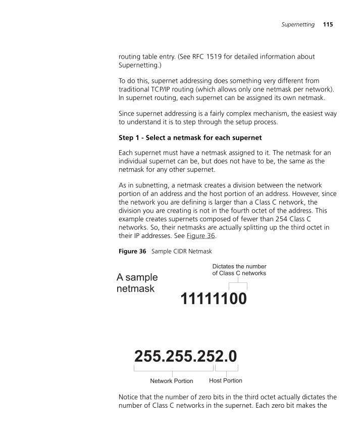
Supernetting 115
routing table entry. (See RFC 1519 for detailed information about Supernetting.)
To do this, supernet addressing does something very different from traditional TCP/IP routing (which allows only one netmask per network). In supernet routing, each supernet can be assigned its own netmask.
Since supernet addressing is a fairly complex mechanism, the easiest way to understand it is to step through the setup process.
Step 1 - Select a netmask for each supernet
Each supernet must have a netmask assigned to it. The netmask for an individual supernet can be, but does not have to be, the same as the netmask for any other supernet.
As in subnetting, a netmask creates a division between the network portion of an address and the host portion of an address. However, since the network you are defining is larger than a Class C network, the division you are creating is not in the fourth octet of the address. This example creates supernets composed of fewer than 254 Class C networks. So, their netmasks are actually splitting up the third octet in their IP addresses. See Figure 36.
Figure 36 Sample CIDR Netmask
Notice that the number of zero bits in the third octet actually dictates the number of Class C networks in the supernet. Each zero bit makes the
11111100
255.255.252.0
Dictates the numberof Class C networks
Host PortionNetwork Portion
A samplenetmask
116 APPENDIX D: ADVANCED IP ROUTING CONCEPTS
supernet twice as large. So, a supernet composed of 8 Class C networks would actually have 3 zeroes (8 = 23).
This would seem very limited since it restricts you to using groups that nicely fit into a power of 2 (1, 2, 4, 8, 16...). However, inconveniently-sized supernets can be accommodated because of a simple fact: a netmask with more 1 bits will override a netmask with fewer 1 bits.
This allows a smaller supernet to share the address space of a larger supernet. If, for example, you had a supernet of size 6 and a supernet of size 2, you could assign the larger supernet an 8 network address space and assign the smaller supernet the portion of that address space that the larger supernet was not using.
Because the smaller supernet netmask has more 1 bits, packets whose address was part of its address space would be routed to the smaller supernet even though the address is also part of the address space dictated by the larger supernet netmask.
Step 2 - Select a range of addresses for each supernet
The range of addresses in a supernet must fit exactly into a space that can be described by its netmask. This means that the zero bits in the netmask must also appear in the first address of the supernet block. For this to be true, the third octet in the address must be an even multiple of the same power of 2 used to form the netmask. For example, if you had created a block of 8 networks, the third octet in the first address will be an even multiple of 8. See Figure 37.
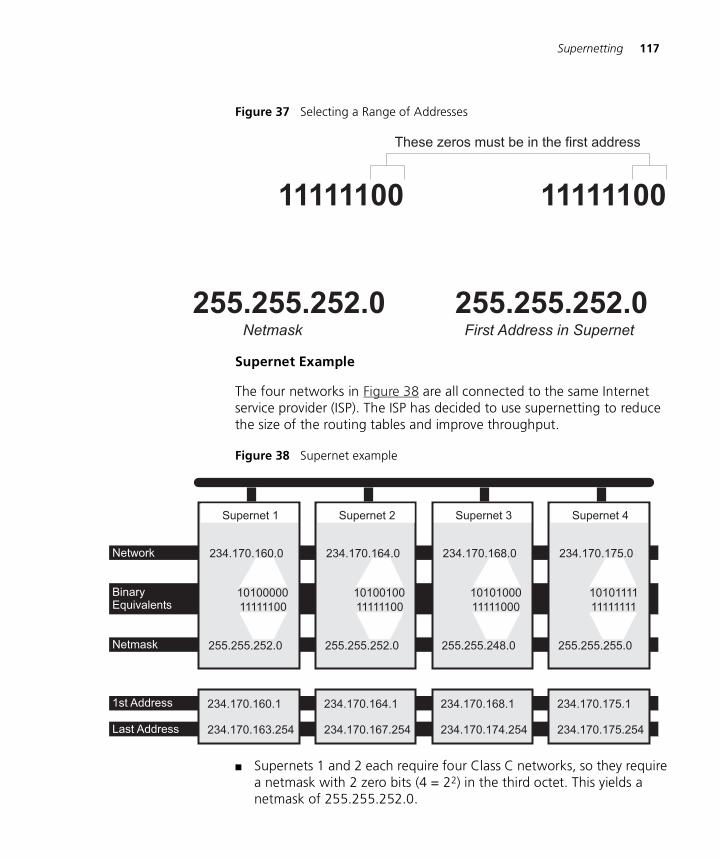
Supernetting 117
Figure 37 Selecting a Range of Addresses
Supernet Example
The four networks in Figure 38 are all connected to the same Internet service provider (ISP). The ISP has decided to use supernetting to reduce the size of the routing tables and improve throughput.
Figure 38 Supernet example
■ Supernets 1 and 2 each require four Class C networks, so they require a netmask with 2 zero bits (4 = 22) in the third octet. This yields a netmask of 255.255.252.0.
255.255.252.0
11111100
These zeros must be in the first address
255.255.252.0
11111100
Netmask First Address in Supernet
234.170.160.0
255.255.252.0
Supernet 1
10100000
11111100
234.170.164.0
255.255.252.0
Supernet 2
10100100
11111100
234.170.168.0
255.255.248.0
Supernet 3
10101000
11111000
234.170.175.0
255.255.255.0
Supernet 4
10101111
11111111
234.170.164.1
234.170.167.254
234.170.160.1
234.170.163.254
234.170.168.1
234.170.174.254
234.170.175.1
234.170.175.254
Network
BinaryEquivalents
Netmask
1st Address
Last Address
118 APPENDIX D: ADVANCED IP ROUTING CONCEPTS
■ Supernet 3 requires 7 Class C address spaces. Since 7 isn't a power of 2, we have to round it up to eight. This gives it a netmask of 255.255.248.0.
■ Supernet 4 is a single Class C network, making it’s netmask 255.255.255.0
Now, assign ranges of addresses. Assume that the ISP is responsible for the network 234.170.0.0 and that its first free addresses are at 234.170.158.0.
The third octet of Supernet 1 has to be an even multiple of 4, so the ISP grants an address range starting at 234.170.160.0 and hopes that the block between 158 and 160 can be filled in later.
Supernet 2 must also begin on an even multiple of 4. The first available address after Supernet 1 conveniently fits the bill. So, supernet 2 extends from 234.170.164.1 to 234.170.167.254.
Supernet 3 requires an even multiple of 8. It also can begin on the next available address.
Since supernet 4 can fit entirely in a single Class C address space, it can use the supernet 3 surplus space. It is therefore given the last Class C address space in the Supernet 3 territory, effectively reducing supernet 3 to only the 7 class C networks it needs.
GLOSSARY
3Com NetworkSupervisor
The 3Com network management application used to manage 3Com’s networking solutions.
10BASE-T The IEEE specification for 10 Mbps Ethernet over Category 3, 4 or 5 twisted pair cable.
100BASE-FX The IEEE specification for 100 Mbps Fast Ethernet over fiber-optic cable.
100BASE-TX The IEEE specification for 100 Mbps Fast Ethernet over Category 5 twisted-pair cable.
1000BASE-T The IEEE specification for 1000 Mbps Gigabit Ethernet over four-pair Category 5 twisted-pair cable.
1000BASE-SX The IEEE specification for 1000 Mbps Gigabit Ethernet over fiber-optic cable.
Access Control List(ACL)
A permission system used to restrict access to a resource. An ACL comprises a list of authorized users.
aging The automatic removal of dynamic entries from the Switch Database which have timed-out and are no longer valid.
Aggregated Links Aggregated links allow a user to increase the bandwidth and resilience between switches by using a group of ports to carry traffic between the switches.
auto-negotiation A feature on twisted pair ports that allows them to advertise their capabilities for speed, duplex and flow control. When connected to a port that also supports auto-negotiation, the link can automatically configure itself to the optimum setup.
backbone The part of a network used as a primary path for transporting traffic between network segments.
120 GLOSSARY
bandwidth The information capacity, measured in bits per second, that a channel can transmit. The bandwidth of Ethernet is 10 Mbps, the bandwidth of Fast Ethernet is 100 Mbps, and the bandwidth of Gigabit Ethernet is 1000 Mbps.
baud The signalling rate of a line, that is, the number of transitions (voltage or frequency changes) made per second. Also known as line speed.
bridge A device that interconnects two LANs of a different type to form a single logical network that comprises of two network segments.
Bridges learn which endstations are on which network segment by examining the source addresses of packets. They then use this information to forward packets based on their destination address. This process is known as filtering.
broadcast A packet sent to all devices on a network.
broadcast storm Multiple simultaneous broadcasts that typically absorb all the available network bandwidth and can cause a network to fail. Broadcast storms can be due to faulty network devices.
CA See Certificate Authority.
cache Stores copies of frequently accessed objects locally to users and serves them to users when requested.
Certificate Authority An organization that issues Digital Certificates.
Classless InterDomainRouting (CIDR)
Routing between two subnets where the size of the subnet is explicitly stated using a Variable Length Subnet Mask (VLSM) rather than being implied by the class of the IP address.
collision A term used to describe two colliding packets in an Ethernet network. Collisions are a part of normal Ethernet operation, but a sudden prolonged increase in the number of collisions can indicate a problem with a device, particularly if it is not accompanied by a general increase in traffic.
CoS Cost of Service. A network prioritization scheme that sorts packets into queues based on tagging or traffic type.
CSMA/CD Carrier-sense Multiple Access with Collision Detection. The protocol defined in Ethernet and IEEE 802.3 standards in which devices transmit only after finding a data channel clear for a period of time. When two
121
devices transmit simultaneously, a collision occurs and the colliding devices delay their retransmissions for a random length of time.
DHCP Dynamic Host Control Protocol. A protocol that lets you centrally manage and automate the assignment of Internet Protocol (IP) addresses in an organization's network.
Digital Certificate Digital Certificates are blocks of data that are used to identify users and systems and encrypt their data. Digital Certificates used by SSL adhere to the X.509 standard.
Distance VectorAlgorithm (DVA)
Routing protocol algorithm that calculates routes for transmitting packets through networks with multiple paths to a destination.
DNS Domain Name System. This system maps a numerical Internet Protocol (IP) address to a more meaningful and easy-to-remember name. When you need to access another device on your network, you enter the name of the device, instead of its IP address.
endstation A computer, printer or server that is connected to a network.
Ethernet A LAN specification developed jointly by Xerox, Intel and Digital Equipment Corporation. Ethernet networks use CSMA/CD to transmit packets at a rate of 10 Mbps over a variety of cables.
Ethernet address See MAC address.
Fast Ethernet An Ethernet system that is designed to operate at 100Mbps.
forwarding The process of sending a packet toward its destination using a networking device.
Forwarding Database See Switch Database.
filtering The process of screening a packet for certain characteristics, such as source address, destination address, or protocol. Filtering is used to determine whether traffic is to be forwarded, and can also prevent unauthorized access to a network or network devices.
flow control A mechanism that prevents packet loss during periods of congestion on the network. Packet loss is caused when devices send traffic to an already overloaded port on a Switch. Flow control prevents packet loss by inhibiting devices from generating more traffic until the period of congestion ends.
122 GLOSSARY
FTP File Transfer Protocol. A protocol based on TCP/IP for reliable file transfer.
full duplex A system that allows packets to be transmitted and received at the same time and, in effect, doubles the potential throughput of a link.
gateway See router.
Gigabit Ethernet IEEE standard 802.3z for 1000 Mbps Ethernet; it is compatible with existing 10/100 Mbps Ethernet standards.
half duplex A system that allows packets to transmitted and received, but not at the same time. Contrast with full duplex.
hub A device that regenerates LAN traffic so that the transmission distance of that signal can be extended. Hubs are similar to repeaters, in that they connect LANs of the same type; however they connect more LANs than a repeater and are generally more sophisticated.
HTTP Hypertext Transfer Protocol. This is a set of rules for exchanging files (text, graphic images, sound, video, and other multimedia files) on the World Wide Web.
HTTPS Hypertext Transfer Protocol over SSL. The term is used to describe HTTP transfers that are encrypted using the SSL protocol.
IEEE Institute of Electrical and Electronics Engineers. This American organization was founded in 1963 and sets standards for computers and communications.
IEEE Std 802.1D, 1998Edition
A standard that defines the behavior of bridges in an Ethernet network.
IEEE Std 802.1p A standard that defines traffic prioritization. 802.1p is now incorporated into the relevant sections of the IEEE Std 802.1D, 1998 Edition.
IEEE Std 802.1Q-1998 A standard that defines VLAN tagging.
IEEE Std 802.3ad A standard that defines link aggregation. 802.3ad is now incorporated into the relevant sections of the IEEE Std 802.3-2002.
IEEE Std 802.3x A standard that defines a system of flow control for ports that operate in full duplex. 802.3x is now incorporated into the relevant sections of the IEEE Std 802.3-2002.
123
IEEE Std 802.1w-2001 A standard that defines Rapid Spanning Tree Protocol (RSTP) behavior.
IEEE Std 802.1X-2001 A standard that defines port-based network access control behavior.
IETF Internet Engineering Task Force. An organization responsible for providing engineering solutions for TCP/IP networks. In the network management area, this group is responsible for the development of the SNMP protocol.
IGMP snooping A mechanism performed by an intermediate device, such as a Layer 2 Switch, that optimizes the flow of multicast traffic. The device listens for IGMP messages and build mapping tables and associated forwarding filters, in addition to reducing the IGMP protocol traffic.
Interior GatewayProtocol (IGP)
IGPs are protocols used in TCP/IP networks to exchange routing information between collaborating routers.
Internet GroupManagement
Protocol
Internet Group Management Protocol (IGMP) is a protocol that runs between hosts and their immediate neighboring multicast routers. The protocol allows a host to inform its local router that it wishes to receive transmissions addressed to a specific multicast group. Based on group membership information learned from the IGMP, a router is able to determine which if any multicast traffic needs to be forwarded to each of its subnetworks.
Intranet An Intranet is an organization wide network using Internet protocols such as web services, TCP/IP, HTTP and HTML. An Intranet is normally used for internal communication and information, and is not accessible to computers on the wider Internet.
IP Internet Protocol. IP is a layer 3 network protocol that is the standard for sending data through a network. IP is part of the TCP/IP set of protocols that describe the routing of packets to addressed devices.
IPX Internetwork Packet Exchange. IPX is a layer 3 and 4 network protocol designed for networks that use Novell® Netware®.
IP address Internet Protocol address. A unique identifier for a device attached to a network using TCP/IP. The address is written as four octets separated with periods (full-stops), and is made up of a network section, an optional subnet section and a host section.
Jitter An expression often used to describe the end-to-end delay variations during the course of a transmission. See also latency.
124 GLOSSARY
LAN Local Area Network. A network of endstations (such as PCs, printers, servers) and network devices (hubs and switches) that cover a relatively small geographic area (usually not larger than a floor or building). LANs are characterized by high transmission speeds over short distances (up to 1000 m).
LLC Logical Link Control. A sublayer of the IEEE data link layer that is located above the MAC sublayer. The LLC sublayer is responsible for MAC sublayer addressing, flow control, error control, and framing.
latency The delay between the time a device receives a packet and the time the packet is forwarded out of the destination port.
line speed See baud.
loop An event that occurs when two network devices are connected by more than one path, thereby causing packets to repeatedly cycle around the network and not reach their destination.
MAC Media Access Control. A protocol specified by the IEEE for determining which devices have access to a network at any one time.
MAC address Media Access Control address; also called hardware or physical address. A layer 2 address associated with a particular network device. Most devices that connect to a LAN have a MAC address assigned to them as they are used to identify other devices in a network. MAC addresses are 6 bytes long.
main port The port in a resilient link that carries data traffic in normal operating conditions.
MDI Medium Dependent Interface. An Ethernet port connection where the transmitter of one device is connected to the receiver of another device.
MDI-X Medium Dependent Interface Cross-over. An Ethernet port connection where the internal transmit and receive lines are crossed.
MIB Management Information Base. A collection of information about the management characteristics and parameters of a networking device. MIBs are used by the Simple Network Management Protocol (SNMP) to gather information about the devices on a network. The Switch contains its own internal MIB.
125
multicast A packet sent to a specific group of endstations on a network.
multicast filtering A system that allows a network device to only forward multicast traffic to an endstation if it has registered that it would like to receive that traffic.
NIC Network Interface Card. A circuit board installed in an endstation that allows it to be connected to a network.
OSPF Open Shortest Path First. A hierarchical Interior Gateway Protocol (IGP) routing algorithm.
POST Power On Self Test. An internal test that a Switch carries out when it is powered-up.
protocol A set of rules for communication between devices on a network. The rules dictate format, timing, sequencing and error control.
QoS Quality of Service. A network prioritization scheme that monitors traffic passing through the network and weights each packet according to the type of data it carries and its progress though the network.
RADIUS Remote Authentication Dial-In User Service. An industry standard protocol for carrying authentication, authorization and configuration information between a network device and a shared authentication server.
Rapid Spanning TreeProtocol
An enhanced version of the Spanning Tree Protocol that allows faster determination of Spanning Tree topology throughout the bridged network.
Rate Limiting The restriction of traffic on a network connection to below its maximum capacity. Typically rate limiting is used with traffic prioritization to ensure that the most important traffic is passed over the link.
repeater A simple device that regenerates LAN traffic so that the transmission distance of that signal can be extended. Repeaters are used to connect two LANs of the same network type.
resilient link A pair of ports that can be configured so that one takes over data transmission should the other fail. See also main port and standby port.
126 GLOSSARY
RIP Routing Information Protocol. An Interior Gateway Protocol for TCP/IP networks. RIP uses distance-vector algorithms (DVA) to calculate least-hops routes to a destination.
RMON IETF Remote Monitoring MIB. A MIB that allows you to remotely monitor LANs by addressing up to nine different groups of information.
router A router is a device on your network which is used to forward IP packets to a remote destination. An alternative name for a router is a gateway.
RSTP See Rapid Spanning Tree Protocol.
SAP Service Access Point. A well-defined location that identifies the user of services of a protocol entity.
Secure Shell See SSH.
Secure Sockets Layer See SSL.
segment A section of a LAN that is connected to the rest of the network using a switch or bridge.
server A computer in a network that is shared by multiple endstations. Servers provide endstations with access to shared network services such as computer files and printer queues.
SMTP Simple Mail Transfer Protocol. An IETF standard protocol used for transferring mail across a network reliably and efficiently (as defined in RFC 821).
SNMP Simple Network Management Protocol. The current IETF standard protocol for managing devices on an TCP/IP network.
Spanning TreeProtocol (STP)
A bridge-based system for providing fault tolerance on networks. STP works by allowing you to implement parallel paths for network traffic, and ensure that redundant paths are disabled when the main paths are operational and enabled if the main paths fail.
SSH Secure Shell. A network protocol that encrypts communication between two devices on a network. An SSH aware application can be used for remote configuration instead of using Telnet.
127
SSL Secure Sockets Layer. A protocol used for encrypting network traffic. It is commonly used to encrypt HTTP traffic between and browser and a Web server.
standby port The port in a resilient link that takes over data transmission if the main port in the link fails.
STP See Spanning Tree Protocol (STP).
subnet mask A subnet mask is used to divide the device part of the IP address into two further parts. The first part identifies the subnet number. The second part identifies the device on that subnet.
supernetting Creating several IP networks that share the same routing entry. See RFC 1519.
switch A device that interconnects several LANs to form a single logical LAN that comprises of several LAN segments. Switches are similar to bridges, in that they connect LANs of a different type; however they connect more LANs than a bridge and are generally more sophisticated.
Switch Database A database that is stored by a switch to determine if a packet should be forwarded, and which port should forward the packet if it is to be forwarded. Also known as Forwarding Database.
TCP/IP Transmission Control Protocol/Internet Protocol. This is the name for two of the most well-known protocols developed for the interconnection of networks. Originally a UNIX standard, TCP/IP is now supported on almost all platforms, and is the protocol of the Internet.
TCP relates to the content of the data travelling through a network — ensuring that the information sent arrives in one piece when it reaches its destination. IP relates to the address of the endstation to which data is being sent, as well as the address of the destination network.
Telnet A TCP/IP application protocol that provides a virtual terminal service, letting a user log into another computer system and access a device as if the user were connected directly to the device.
TFTP Trivial File Transfer Protocol. Allows you to transfer files (such as software upgrades) from a remote device using the local management capabilities of the Switch.
traffic prioritization A system which allows data that has been assigned a high priority to be forwarded through a switch without being obstructed by other data.
128 GLOSSARY
unicast A packet sent to a single endstation on a network.
Variable LengthSubnet Mask (VLSM)
A suffix to an IP address that indicates the size of the subnet that contains it. Taking the address 192.168.1.1/24 as an example, the VLSM is /24 and indicates that the first 24 bits of the address form the network part of the address.
VLAN Virtual LAN. A group of location- and topology-independent devices that communicate as if they are on the same physical LAN.
VLAN tagging A system that allows traffic for multiple VLANs to be carried on a single link.
WAN Wide Area Network. A communications network that covers a wide area. A WAN can cover a large geographic area, and may contain several LANs within it.
X.509 A standard for Digital Certificates as used by SSL.
INDEX 129
INDEX
Numbers802.1D
priority levels 48traffic classification 48
AAccess Control Lists 73addresses
classes 109IP 88, 107
advertise RIP mode 91advertisement address 93aggregated links 14, 23aging time, definition 46alarm events 58Alarms (RMON group) 56, 57ARP (Address Resolution Protocol)
cache 89, 94defined 94location in OSI Reference Model 83reply 95request 95
automatic IP configuration 67auto-negotiation 14, 22
BBackup 15bandwidth 21BPDUs. See Bridge Protocol Data UnitsBridge Identifier 38Bridge Protocol Data Units 38Broadcast Storm Control 18
Ccable
maximum length 100, 101cache, ARP 94Capture (RMON group) 57CIDR (Classless InterDomain Routing) 114Configuration
Restore 15Save 15
conventionsnotice icons, About This Guide 10text, About This Guide 10
CoSconfiguring traffic 52How traffic is processed to provide CoS 51
Ddata link layer
IP 83default gateway 112default route, IP 86
gateway address 89Default VLAN 61defining IP interfaces 89Designated Bridge 39Designated Bridge Port 39disabled
RIP mode 91dynamic route, IP 86
Eenabled RIP mode 91errors
routing interface 89VLAN 89
event notification 18Events (RMON group) 56, 57extended network prefix 111
FFast Ethernet configuration rules 100Filter (RMON group) 56, 57flow control 22full duplex configuration rules 101
Ggateway address 85Gigabit Ethernet configuration rules 99glossary 119
HHello BPDUs 40History (RMON group) 56, 57Hosts (RMON group) 57Hosts Top N (RMON group) 57
130 INDEX
IICMP (Internet Control Message Protocol)
description 97location in OSI Reference Model 83
IEEE Std 802.1Q-1998 61IEEE Std 802.3-2002 flow control 15, 22IGMP multicast filtering 31index, VLAN interface 88interfaces
IP 89Internet
addresses 107InterNIC 108IP (Internet Protocol)
addresses 88, 108interfaces 89
IP address 67, 107classes of 109defined 108derivation 108division of network and host 108example 110netmask for supernet
supernetworking 114network layer 83next hop 83obtaining 108RIP 90routing table 85subnet mask 110subnetwork portion 110supernet portion 114
IP interfacesdefining 89parameters 88
IP multicastaddressing 29
IP routingaddress classes 109administering 89defining static routes 90features and benefits 84OSI reference model 83router, interface 84routing table 85, 86transmission process 83types of routes 89
Llearn RIP mode 91learned SDB entries 46
MMAC (Media Access Control)
addressesIP address 108located with ARP 94use in IP routing 96
managementIP interface 85
manual configuration 67masks
subnet 88, 110Matrix (RMON group) 57Max Age 40metric, RIP 85multicast filtering 29
IGMP 31multicasts, description 29multiple IP interfaces 87
Nnetmask for supernet 114network
addresses 107layer 83security 71segmentation 84
network configuration examples 104network login 75non-aging learned SDB entries 46
Oobtaining
registered IP address 108OSI Reference Model 83OSPF (Open Shortest Path First)
location in OSI Reference Model 83
Ppath costs. See port costspermanent SDB entries 46poison reverse 92port costs, default 39port security 18, 71, 74port trunks
example 27priority in STP 38priority levels
802.1D 48
INDEX 131
RRADIUS 77, 80
authentication 77Rapid Spanning Tree Protocol (RSTP) 16, 36registered IP address, obtaining 108Remote Monitoring. See RMONRestore 15RIP (Routing Information Protocol)
advertisement address 93defined 90location in OSI Reference Model 83poison reverse 92route configuration 86router mode 91
RMON 17alarm events 58benefits 57groups 55
Root Bridge 38Root Path Cost 39Root Port 39routers
interface 84routing
overview 82routing table, IP
contents 85default route 86, 89described 85dynamic routes 86metric 85static routes 86, 89status 85
SSave 15SDB. See Switch Databasesecurity
network 71segment, maximum length 100segmentation, network 84Spanning Tree Protocol, see STP 35static route, IP 86, 90Statistics (RMON group) 56, 57status, routing table 85STP 35
avoiding the subdivision of VLANs 44Bridge Identifier 38Bridge Protocol Data Units 38default port costs 39default priority 38
Designated Bridge 39Designated Bridge Port 39example 40Hello BPDUs 40Max Age 40priority 38Root Bridge 38Root Path Cost 39Root Port 39using on a network with multiple VLANs 44
subnet mask 110defined 110example 110IP interface parameter 88numbering 111routing table 85
subnets 110subnetworking
defined 110subnet mask 110
sub-networks. See subnetssupernet 114supernet mask
example 115range of addresses 116
supernet, example 117supernetting
defined 114netmask 114
Switch Database 45switch management login 71
Ttopology rules for Fast Ethernet 100topology rules with full duplex 101traffic classification
802.1D 48traffic prioritization 17, 47
802.1D 48
VVLANs 59
benefits 60Default 61defining the information for 63IEEE Std 802.1Q-1998 61
VLANs (virtual LANs)errors 89interface index 88
VLSMs (Variable Length Subnet Masks) 113

132 INDEX